WO2022138712A1 - 発電モジュールセットを評価する方法 - Google Patents
発電モジュールセットを評価する方法 Download PDFInfo
- Publication number
- WO2022138712A1 WO2022138712A1 PCT/JP2021/047544 JP2021047544W WO2022138712A1 WO 2022138712 A1 WO2022138712 A1 WO 2022138712A1 JP 2021047544 W JP2021047544 W JP 2021047544W WO 2022138712 A1 WO2022138712 A1 WO 2022138712A1
- Authority
- WO
- WIPO (PCT)
- Prior art keywords
- power generation
- generation module
- module set
- modules
- score
- Prior art date
- Legal status (The legal status is an assumption and is not a legal conclusion. Google has not performed a legal analysis and makes no representation as to the accuracy of the status listed.)
- Ceased
Links
Images







Classifications
-
- H—ELECTRICITY
- H02—GENERATION; CONVERSION OR DISTRIBUTION OF ELECTRIC POWER
- H02J—ELECTRIC POWER NETWORKS; CIRCUIT ARRANGEMENTS OR SYSTEMS FOR SUPPLYING OR DISTRIBUTING ELECTRIC POWER; SYSTEMS FOR STORING ELECTRIC ENERGY
- H02J3/00—Circuit arrangements for AC mains or AC distribution networks
- H02J3/38—Arrangements for feeding a single network from two or more generators or sources in parallel; Arrangements for feeding already energised networks from additional generators or sources in parallel
-
- H—ELECTRICITY
- H02—GENERATION; CONVERSION OR DISTRIBUTION OF ELECTRIC POWER
- H02S—GENERATION OF ELECTRIC POWER BY CONVERSION OF INFRARED RADIATION, VISIBLE LIGHT OR ULTRAVIOLET LIGHT, e.g. USING PHOTOVOLTAIC [PV] MODULES
- H02S50/00—Monitoring or testing of PV systems, e.g. load balancing or fault identification
Definitions
- This disclosure relates to a method of evaluating a power generation module set.
- the performance of the power generation module deteriorates or the power generation module fails over time. As a result, the output of the power plant is reduced. Furthermore, its performance degradation varies from power generation module to power generation module. As a result of performance degradation, power plants generate electricity in power generation modules that differ from each other or have different performances. In this state, the mismatch loss rate increases and efficient power generation is not performed.
- Performance variations also exist during manufacturing or when installing a power plant.
- the variation in performance deterioration increases year by year.
- breakdowns occur irregularly. Therefore, the mismatch loss rate increases with the number of years of operation.
- one object of the present disclosure is to evaluate, for example, the amount of power generated by a power plant including a power generation module or a power generation module set that is a part thereof by using the power generation data of a power generation module in operation, and further to generate power.
- the purpose is to provide new technology that enables repowering of power plants.
- a method of evaluating a power generation module set is provided.
- the method may further comprise providing the power generation characteristics of each of the power generation modules.
- the method may further comprise finding a score for the power generation module set.
- a flowchart of an evaluation method according to an embodiment is shown.
- the configuration of the power generation module set according to one embodiment is schematically shown.
- the configuration of the power generation module set according to one embodiment is schematically shown.
- the configuration of the power generation module set according to one embodiment is schematically shown.
- the IV characteristics of the target power generation module set according to the embodiment are shown.
- the IV characteristics of each IV characteristic of the comparative power generation module set according to one embodiment are shown.
- the IV characteristics of the target power generation module set according to the embodiment are shown.
- the IV characteristics of each IV characteristic of the comparative power generation module set according to one embodiment are shown.
- the IV characteristics of the target power generation module set according to one embodiment are shown.
- the exchange operation of the comparative power generation module set which concerns on one Embodiment is shown.
- the exchange operation of the comparative power generation module set which concerns on one Embodiment is shown.
- the exchange operation of the comparative power generation module set which concerns on one Embodiment is shown.
- the exchange operation of the comparative power generation module set which concerns on one Embodiment is shown.
- the table which summarized the result of the comparative power generation module set in an Example is shown.
- the graph of the power generation amount of the comparative power generation module set in an Example is shown.
- the configuration of the power generation module set according to one embodiment is schematically shown.
- the IV characteristics of the target power generation module set according to the embodiment are shown.
- the IV characteristics of each IV characteristic of the comparative power generation module set according to one embodiment are shown.
- a block diagram illustrating a configuration of a computer system for evaluating and repowering a power generation module set according to an embodiment is shown.
- a method according to an embodiment of the present disclosure will be described with reference to FIG. S101 provides the power generation characteristics (for example, IV curve) of the modules included in the target power generation module set.
- the score for example, the output of power generation
- the power generation characteristics of the modules included in the target power generation module set is calculated.
- the IV curve, string IV curve, array IV curve, etc. of each module may be obtained, and the power generation amount of the target power generation module set may be obtained.
- a replacement operation is performed on the module of the target power generation module set, and a power generation module set (comparative power generation module set) is virtually generated. For example, the exchange operation may be repeated to search for a better power generation module topology.
- the score of the comparative power generation module set is calculated.
- the score of the target power generation module set may be simply obtained. In some embodiments, further repowering suggestions or executions may be made based on the scores obtained.
- a “module” or “power generation module” generally means that an element or cell that produces or consumes electrical energy is enclosed in an enclosure for environmental resistance and has a specified output. It refers to the smallest unit of power generation installed in a power plant, etc.
- a “power generation module” may be defined as an electrical component with an IV curve.
- the “power generation module” may be an electric circuit exhibiting IV characteristics, which is defined as indivisible in terms of computational problems and separable from other parts in a calculation process using an IV curve synthesis simulation.
- Power generation may use so-called renewable energy as an energy source.
- the power generation may be solar power generation.
- the generator may be, for example, but is not limited to, a battery, a battery storage system, a fuel cell, a wind power generator, a geothermal power generator, or may include these.
- the generator may be a combination of a plurality of generators of the same type, or may include a combination thereof.
- the "module" may be a solar cell module.
- the power generation module may be a fuel cell power generation module.
- the power generation module may include a thermoelectric conversion element (thermoelectric power generation module).
- the power generation module may include a piezoelectric element (vibration power generation module).
- the power generation module may be a generator.
- a generator generally refers to a device that converts kinetic energy into electrical energy by applying electromagnetic induction by a coil and a magnet.
- the power generation module may comprise a combination of multiple types of power generation modules.
- the power generation module may generate DC power.
- the "power plant” or “power generation module set” used in the present specification generally refers to a facility equipped with a power generation facility (for example, a power generation module) to generate power.
- topology generally refers to a state defined by power generation modules, their electrical connection relationships, and environmental conditions. In some embodiments, it refers to the relationship of electrical connections (electrical wiring) between electrical components (power generation modules, DC conditioners, DC / AC converters, etc.), not necessarily the physical or spatial location of the electrical components. Not specified.
- changing the topology refers to the operation of fixing a predetermined connection relationship (frame and position of each power generation module, cable arrangement) and replacing the power generation module. In some embodiments, changing the topology refers to an operation that includes changing the connection relationship in addition to replacing the power generation module. In some embodiments, changing the topology may include operations that cause changes in the environment (cutting surrounding trees, cleaning the surface).
- Some embodiments may include replacement of electrical components (elements, circuits, etc.) that directly or indirectly affect electrical connectivity, such as PCS, cables, blocking diodes, fuses, and the like.
- replacement may be replacement with another component that is new or used, replacement with a component of a different type, repair of an existing component, or change (improvement, deterioration) in performance.
- a "power generation module set” generally refers to a set of modules and other electrical components that are subject to performing the methods of the present disclosure.
- a power generation module set refers to a set of one or more power generation modules belonging to it.
- the modules in the power generation module set may be configured to be electrically connected or connected to each other in some way.
- the plurality of modules in the power generation module set may not necessarily be electrically connected or may not be configured to be connected.
- a power generation module set of a power generation module of one power plant and a power generation module of another power plant may be configured.
- the "power generation module set” may be one power plant.
- a plurality of power generation modules arranged in two individual power plants may be defined as one power generation module set.
- the power generation module set may have one or more strings.
- the string may have one or more modules.
- the string may be composed of one or more power generation modules (sometimes referred to simply as “modules” herein) connected to direct current.
- the module set does not necessarily have to contain one or more complete strings.
- the power generation module set may be configured with a portion of the string.
- the solar radiation conditions may differ within one string of a photovoltaic system.
- the module will have different power generation characteristics.
- the power generation module set may be equipped with one or more DC conditioners.
- One or more strings may be connected in parallel to each DC conditioner.
- the power generation module set may be configured to have one DC conditioner and one or more strings connected to it.
- the score is calculated only for the power generation module of the string connected to that DC conditioner.
- FIG. 2 shows a power generation module set 100 according to an embodiment.
- the power generation module set 100 shown in FIG. 2 has one DC conditioner 110.
- a plurality of strings 111, 112, 113 (three in FIG. 2) are connected in parallel to each other and connected to the DC conditioner 110.
- Multiple modules are connected in series to each string.
- N modules 1111, 1112, ..., 111n are connected to the string 111.
- modules in the middle are omitted, and module codes of other strings are omitted.
- This module set can be evaluated, scored, or repowered.
- the power generation module set may be configured to have a plurality of DC conditioners.
- One or more strings may be connected to their respective DC conditioners.
- FIG. 3 shows a power generation module set 200 according to an embodiment.
- the power generation module set 200 shown in FIG. 3 has two DC conditioners 210 and 220. These DC conditioners 210 and 220 are connected to the DC / AC converter 200A.
- a plurality of (three in FIG. 3) strings 211,212, 213 are connected in parallel to each other and connected to the first DC conditioner 210.
- the three strings 221,222,223 are connected in parallel to each other and are connected to the second DC conditioner 220.
- Multiple modules are connected in series to each string. For example, n modules 211, 2112, ..., 211n are connected to the string 211.
- modules in the middle are omitted, and module codes of other strings are omitted.
- a group of modules under the control of a plurality of DC conditioners can be called a module set. This module set can be evaluated, scored, or repowered.
- the power generation module set may be configured to include a DC / AC converter and all or part of a DC conditioner, a string, and a power generation module connected to the DC / AC converter.
- the power generation module set may be configured to include a plurality of DC / AC converters and all or part of a DC conditioner, a string, and a power generation module connected to each of the DC / AC converters.
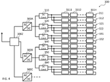
- FIG. 4 shows a power generation module set 300 according to an embodiment.
- the power generation module set 300 shown in FIG. 4 has three DC / AC converters 300A, 300B, and 300C. These DC / AC converters 300A, 300B, and 300C are connected in parallel to each other and further connected to the AC current collector box (or interconnection point) 300Z. Power is provided to the outside from the AC current collector box (or interconnection point) 300Z.
- a plurality of DC conditioners are connected to each of the DC / AC converters 300A, 300B, and 300C.
- Three DC conditioners 310, 320, and 330 are connected to the first DC / AC converter 300A.
- Three DC conditioners 340, 350, and 360 are connected to the second DC / AC converter 300B.
- the DC conditioner connected to the third DC / AC converter 300C is omitted in the drawing.
- Multiple strings are connected to each DC conditioner.
- a plurality of (two in FIG. 4) strings 311, 312 are connected in parallel to each other and connected to the first DC conditioner 310.
- the strings 321 and 322 are connected in parallel to each other and connected to the second DC conditioner 320, and the strings 331 and 332 are connected in parallel to each other and connected to the third DC conditioner 330. ..
- the symbols of other strings are omitted.
- Multiple modules are connected in series to each string. For example, n modules 3111, 3112, ..., 311n are connected to the string 311.
- modules in the middle are omitted, and module codes of other strings are omitted.
- a group of modules under the control of a plurality of DC / AC converters can be called a module set. This module set can be evaluated, scored, or repowered.
- the module set may be defined as part of the above configuration.
- a part of a plurality of modules under the control of one DC conditioner may be defined as a module set.
- a part of a plurality of modules under the control of a plurality of DC conditioners may be defined as a module set.
- a part of a plurality of modules under the control of a plurality of DC / AC converters may be defined as a module set.
- the entire power plant may be defined as one module set.
- a part of a plurality of modules under the control of a power plant may be defined as a module set.
- Multiple power plants may be defined as one module set.
- a part of a plurality of modules under the control of a plurality of power plants may be defined as a module set.
- the module set may be defined by arbitrary, predetermined or other conditions such as geographical conditions, intention of the business operator, purpose of improving calculation efficiency, and the like.
- the photovoltaic module set may be configured to have one DC conditioner and one or more strings connected to it.
- the photovoltaic module set may include a plurality of DC conditioners.
- the photovoltaic power generation module set may be configured to have a plurality of DC conditioners and one DC / AC converter to which they are connected.
- the photovoltaic module set may include a plurality of DC / AC converters.
- the photovoltaic module set may be one or more photovoltaic power plants / systems.
- the target power generation module set (also referred to as an evaluated power generation module set) may be an existing (or newly installed) power generation module set.
- the target power generation module set does not have to be a power generation module set that actually exists or is planned to be newly installed.
- the target power generation module set does not have to physically exist.
- the target power generation module set may be a virtual power generation module set.
- the comparative power generation module set may be a virtual power generation module set.
- the target and / or comparative power generation module set may be a power generation module set that exists in calculation or concept.
- the comparative power generation module set may be a power generation module set that has undergone secular variation after repowering.
- the secular variation may be a gradual change (for example, deterioration) in the power generation characteristics, an irregular change (for example, a failure), or the like.
- Secular variation may be added to the comparative power generation module set obtained by performing a replacement operation on the modules in the target power generation module set or the modules to which the replacement modules are added. Secular variation may vary from module to module. Secular variation may occur uniformly for the module immediately after repowering. Secular variation may occur non-uniformly with respect to the module. For example, a module that does not contribute to power generation may not undergo secular variation, and a module that contributes to power generation may undergo secular variation.
- secular variation may occur for randomly or stochastically selected modules. It may be assumed that these changes occur at predetermined or arbitrary times such as every year and every month.
- the power generation module set is evaluated at the time when the predetermined period has passed after the repowering is performed (for example, 1 year, 2 years, 3 years, 5 years, 7 years, 10 years, etc.). It can be performed.
- the replacement module may be a new module.
- the replacement module may be a used module.
- the replacement module may be provided by a power generation module set, a power plant, or the like other than the target power generation module set.
- the replacement module may include a predetermined number of replacement modules.
- the number of replacement modules may be determined, for example, without limitation, according to the customer's request, budget, and the like.
- the "power generation characteristic” generally refers to the current-voltage characteristic.
- the power generation characteristic may be an IV characteristic, an IV characteristic curve, or an IV curve.
- the power generation characteristic may be a PV characteristic curve or a PV curve.
- the power generation characteristic may be acquired for the entire region of at least one of current and voltage (current or voltage from zero to maximum, voltage minus to maximum). Power generation characteristics may be acquired for at least a portion of current and voltage. Power generation characteristics may be defined as a function or set of these characteristics.
- the power generation characteristics of each module may be acquired by measurement. For example, it may be measured by a voltage ammeter. For example, the power generation characteristics may be measured using an IV curve tracer.
- the measured current / voltage value and other measurement information may be transmitted by a wireless, wired, power line communication (PLC) method, pulsed power line communication (PPLC) method, or the like.
- the measurement information may be transmitted as a digital signal or an analog signal.
- the power generation characteristics of each module may be acquired by estimation or calculation based on the measurement results.
- the power generation characteristics may be estimated from the operating point data.
- the entire IV curve may be inferred.
- some may be estimated with high accuracy and other parts may be estimated with relatively low accuracy by approximation or the like.
- parts such as the vicinity of the operating point and the vicinity of the maximum power output point may be estimated with high accuracy, and the others may be represented by a simple shape such as a straight line to the open circuit voltage (Voc) and the short circuit current (Isc). .
- the power generation characteristics may be estimated from the name plate value.
- the power generation characteristics may be estimated by combining the name plate IV curve and the failure content (for example, obtained by non-contact electrical measurement).
- power generation characteristics may be estimated based on electroluminescence (EL) measurements.
- power generation characteristics may be estimated based on multiple factors such as actual measurements, estimates based on measurement results, estimates made without measurements, data, and the like.
- correction processing may be performed on the acquired power generation characteristics.
- Power generation characteristics are from environmental conditions (eg, solar radiation conditions, season, temperature, wind speed, wind direction, latitude, altitude, shadow of objects, surface angle, power generation module angle, sun angle, weather, humidity, last precipitation. It depends on the elapsed time, reflected light from nearby buildings, terrain, water areas, etc., fog, air pollution, snow cover, frost, atmospheric components, etc.). As a result, uniformly comparing or synthesizing a plurality of power generation characteristics obtained under different environmental conditions may give erroneous results. Therefore, the acquired power generation characteristics may be converted so as to have the power generation characteristics obtained under the same or substantially the same conditions. For example, the power generation characteristics may be converted into standard conditions (STE, 1000 W, 25 ° C.).
- the power generation characteristics may be converted into standard conditions by a uniform method. For example, conversion may be performed on the power generation characteristics of each module based on the environmental conditions typically measured in or near the power generation module set.
- the environmental conditions within the power generation module set differ depending on where each module is installed.
- the conversion may be performed for the power generation characteristics according to each module in consideration of the environmental conditions (for example, the amount of solar radiation G and the temperature T) received by each module.
- the power generation characteristics may be quantized with respect to at least one of voltage and current.
- the power generation characteristic can be analog information. For example, voltage values (current values) at different current values (voltage values) cannot be summed in the voltage (current) direction. Therefore, the acquired power generation characteristics may be converted into data that takes a predetermined current value (voltage value) in advance. The transformation is sometimes called quantization.
- the quantized power generation characteristics can be numerically summed in the current and / or voltage directions.
- the IV curve obtained as a continuous function may be synthesized without quantization. At that time, for example, IV curve estimation, approximation, or the like may be performed.
- the region between discrete measurement points on the IV curve may be interpolated continuously or discretely by linear, curved or other means.
- the IV curve does not have to be digitized and retained. For example, when there is a request for the other value corresponding to a specific voltage or current on the IV curve, the voltage or current may be prepared in an analog manner by actually applying the voltage or current to the power generation module.
- the power generation characteristics of the plurality of modules may be combined.
- the plurality of modules connected in series in one string or the plurality of power generation characteristics of the string may be combined by summing up in the voltage direction at each current value.
- the power generation characteristics of the modules or strings connected in parallel may be combined by summing in the current direction at each voltage value.
- only the first quadrant of the IV curve (I ⁇ 0, V ⁇ 0) may be used to synthesize the power generation characteristics.
- the second quadrant (I ⁇ 0, V ⁇ 0) may be used in addition to the first quadrant of the IV curve for the synthesis of power generation characteristics.
- the third quadrant and / or the fourth quadrant may be used for synthesizing the power generation characteristics.
- V 0.
- the power generation characteristics may be combined across a plurality of modules connected in series within each string. In this case, the power generation characteristics may be obtained by adding each current value in the voltage direction.
- the power generation characteristics synthesized by each string may be referred to as string power generation characteristics (string IV curve).
- the string power generation characteristics may be synthesized over a plurality of strings connected in parallel for each DC conditioner.
- the power generation characteristics may be obtained by adding in the current direction at each voltage value.
- the power generation characteristics synthesized by each DC conditioner may be referred to as array power generation characteristics (DC conditioner, power generation characteristics, array IV curve).
- the parallel connection does not necessarily have to be made for the string directly under the DC conditioner.
- the synthetic IV curve of a string composed of a combination of parallel and serial connections can be determined by performing series and parallel synthesis.
- the term "score” as used in the present invention generally refers to the power generation performance of a power generation module set.
- the score may be determined in response to one or more power generation characteristics obtained from one or more power generation modules in a set of power generation modules and may be defined as a function thereof. .. The score does not have to be defined by the function.
- the score may be determined by a reference table. Scores may be defined by the same or substantially the same function across multiple sets of power generation modules. The score may be defined by different functions across multiple sets of power generation modules. Scores may be expressed in natural numbers, real numbers, complex numbers, tensors, probability distributions, and other representations.
- the score may be the sum of the maximum generated power of the power generation module.
- the score may be defined as a function based on a value or data structure assigned to each power generation module or other calculation unit. The score does not necessarily have to be defined directly using the power generation characteristics.
- the score may be defined using environmental conditions such as the influence of shades such as trees.
- the score may be Pmax of the IV curve.
- the IV curve may be a string IV curve, an array IV curve, or the like.
- the score may be, for example, but not limited to, Pmax itself, a function of Pmax (for example, a function of Pmax and the number of exchanged modules).
- the total score of DC conditioners connected in parallel may be defined as the sum of Pmax of each DC conditioner.
- the score may be the sum of the maximum power (Pmax) of the plurality of DC conditioners.
- the score may be a function of the sum of the maximum power (Pmax) of the plurality of DC conditions and other values.
- the score is, for example, not limited to the number of maximum points in the PV curve of the DC conditioner; the number of sabotaged panels in the DC conditioner; the construction cost for the replacement operation; the coefficient that decreases as the simulation progresses. It may be a number multiplied by; the total maximum power when the exchange operation is interrupted by an odd process; and so on.
- the score is, for example, not limited to the amount of power generation (power generation output, power generation amount x time); the score before repowering or the power generation amount up to the evaluation time (power generation amount x [time from the start of use to the present]).
- the score after repowering or the amount of power generation from repowering to the end of its life (power generation amount x [currently scheduled to end use (for example, 30 years)]; etc. may be used.
- the score is not limited, for example. It may be the number of years required for collection (collection period), the repair cost temporarily incurred / the number of years required for collection, and the like.
- the score may be defined by the same function or expression for both the target power generation module set and the comparative power generation module set. In some embodiments, the score may be defined by a different function or expression between the target generation module set and the comparative generation module set.
- the first score may be defined as the amount of power generated (Px time)
- the second score may be defined as Pmax.
- Comparison between the target power generation module set and the comparative power generation module set, or between multiple power generation module sets can be performed based on the absolute value of the score, the ratio (division), the difference, and other relationships.
- Example 1 Evaluation of target power generation module set> First, the evaluation and repowering of a power generation module set defined as having one DC conditioner will be described.
- FIG. 5 shows the topology of a certain solar module set 400 and the results (IV curve) of measurements and evaluations actually performed on it.
- the module set 400 of FIG. 5 has one DC conditioner 410, three strings 411,421,413 connected in parallel to supply power to the DC conditioner 410, and a plurality of solar modules 4111 under its control. It is configured to have ⁇ 4136.
- the strings 411,421,413 each have six solar modules 4111-4116, 4121-4126, 4131-4136 connected in series.
- the current and voltage operation data of each module was acquired by the PPLC method. Those operational data were partially obtained as an IV curve. Based on the acquired operation data, the IV curve of the entire current and voltage (within the first quadrant) was estimated. Each IV curve obtained was converted to standard conditions. The figures for each example show the IV curves thus obtained by estimation and conversion to standard conditions. Acquisition of the IV curve for each module is not limited to this method. Other methods may be used.
- the IV curve obtained for each module was quantized.
- the value of each IV differs between modules and cannot be combined (numerically added) in the V direction or the I direction as it is.
- the voltage was quantized from 0V to 25V to a value of 0.01V, and the current was quantized from 0A to 5A to a value of 0.01A.
- Quantization of IV curve data is not limited to this method. Other methods may be used.
- the IV curves were added for each string in the V (horizontal axis) direction to generate a string IV curve.
- the generated string IV curves are shown on the left side of each string.
- the string IV curves of strings 411,421,413 were added together in the I (vertical) direction.
- the combined array IV curve is the IV characteristic of the DC conditioner 410. It is shown below the string IV curve.
- the DC conditioner 410 adjusts the operating points ⁇ Vop10, Iop10 ⁇ so as to maximize the electric power.
- the Vop 10 thus determined have the same value over the strings 411, 421, 413 connected in parallel.
- the string IV curves of strings 411,421,413 are different. Therefore, according to each string IV curve, operating currents (string currents) Iop11, Iop12, and Iop13 corresponding to Vop10 flow in each string 411,421,413.
- Each module is required to operate at the voltage corresponding to the corresponding string currents Iop11, Iop12, Iop13 according to each IV curve.
- this operating point is shown as the intersection of intersecting straight lines in each module.
- the theoretical maximum operating point in each module is represented by the contact point with the rectangular IV curve inscribed in the IV curve.
- the maximum operating power of each module corresponds to its rectangular area.
- the module 4121 has extremely good characteristics as an IV curve. However, despite the Pmax of 232W, the module 4121 actually generates only 61W, or 26% of the ideal power. It can be seen that such a module exists. As a result, this module set offers significantly lower power from the maximum that would ideally be obtained.
- the value obtained by simply adding the Pmax of the modules under the control of the DC conditioner 410 was calculated as 2339W.
- the ratio is 76%. That is, it is evaluated that the current DC conditioner 410 outputs an electric energy of 76% of the theoretical maximum value.
- Example 2 Repowering> Next, we will see how much such a power generation module set can be improved by the present invention.
- the target power generation module set 400 was repowered using the method according to the embodiment of the present application to generate a comparative power generation module set 400R.
- FIG. 6 shows the topology of the repowered power generation module set 400R and the results of actual measurements and evaluations (IV curve). Each graph is numbered with a module in the target power generation module set 400.
- the power generation characteristic of the DC conditioner 410R has a slightly lower operating voltage than the original power generation characteristic 410, but has a higher operating current. As a result, the total electric energy became 2188W. That is, it is evaluated that the DC conditioner 410R after this repowering can provide electric power up to 93% of the theoretical maximum value (2339W).
- modules have an operating voltage of 0%.
- These modules do not contribute to power generation.
- the power generation module set can output a higher amount of power as a result even if it has a configuration (topology) having modules that do not work.
- a power generation module replacement operation may be performed such that a string has a module that does not generate power.
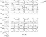
- the module set 500 shown in FIG. 7 is connected in parallel with two DC conditioners 510 and 520 to supply power to the DC conditioners 510 and 520, respectively, with three strings 511,512,513; 521,522. It is composed of 523 and a plurality of solar modules under its control.
- the strings 511 and 521, 513, 521, 522, 523 have six solar modules 5111 to 5116, 5121 to 5126, 5131 to 5136, 5211 to 5216, 5221 to 5226, 5231 to 5236 connected in series, respectively. is doing.
- the theoretical values of the DC conditioners 510 and 520 (the sum of the Pmax of the modules under their control) were 3201W and 2766W, respectively.
- the actual power generation amounts of the DC conditioners 510 and 520 were 2526W and 2063W, respectively. Therefore, the ratios of the operating power to the theoretical value were 78% and 74%, respectively.
- Example 4 the target power generation module set 500 was repowered using the method according to the embodiment of the present application to generate a comparative power generation module set 500R.
- FIG. 8 shows the topology of the repowered power generation module set 500R and the results of actual measurements and evaluations (IV curve). Each graph is numbered with a module in the target power generation module set 500.
- the theoretical values of the first and second DC conditioners 510 and 520 before repowering were 3201 W and 2766 W, respectively, and the difference was 435 W.
- the theoretical values of the first and second DC conditioners 510R and 520R before repowering were 3962W and 2005W, respectively, and the difference was 1957W.
- the result of the repowering of this example is that the module having the IV characteristic having a relatively high capacity and the module having the IV characteristic having a relatively low capacity are separated, and one of them is put together under the control of one DC conditioner. Can be interpreted.
- Modules with zero operating power were also found in the topology after repowering. Specifically, it was found that the three modules of the module 5111 of the string 521R; the modules 5122 and 5213 of the string 523R; did not substantially contribute to power generation.
- the number of modules that did not substantially contribute to power generation decreased. Therefore, it can be considered that positively reducing the number is effective repowering.
- the number of modules that do not substantially contribute to power generation may be reduced by repowering. However, there may be cases where it is not necessary to actively reduce the number.
- the number of modules that do not substantially contribute to power generation does not have to change with repowering. For example, the number may increase.
- modules that do not substantially contribute to power generation are collected under the control of one DC conditioner (second DC conditioner 520R) by repowering.
- the module replacement operation may include a new module or a replacement module.
- a replacement operation including a new module.
- FIG. 9 shows the topology of the target power generation module set 600, which is the basis of the following Examples 6 to 9, and the result (IV curve) of the measurement and evaluation actually performed on the topology.
- the theoretical values of the output power amounts of the first and second DC conditioners were 5606W and 5942W, respectively.
- Example 6 First, we prepared three new modules. The modules in the target power generation module set 600 of FIG. 9 were not exchanged with each other, and the exchange operation was performed in which the three modules having the worst Pmax were exchanged with three new modules.
- FIG. 10 shows the topology. As a result, the output power amounts of the first DC conditioner, the second DC conditioner, and the entire module set were 4794 W (no change), 5863 W, and 10657 W, respectively.
- Example 7 First, three new modules were prepared in the same manner as in Example 3. The modules in the target power generation module set 600 of FIG. 9 were not exchanged with each other, but three modules to be exchanged were selected by searching, and an exchange operation was performed in which they were exchanged with three new modules.
- FIG. 11 shows the topology. As a result, the output power amounts of the first DC conditioner, the second DC conditioner, and the entire module set were 5333W, 5517W, and 10851W, respectively.
- Example 8> The search was performed on the condition that the modules in the target power generation module set 600 of FIG. 9 were exchanged with each other without exchanging with a new module at all.
- FIG. 12 shows the topology and the trajectory of the movement of the module.
- the output power amounts of the first DC conditioner, the second DC conditioner, and the entire module set were 4416W, 6341W, and 10757W, respectively.
- Example 9 First, we prepared three new modules. The search was conducted on the condition that up to nine modules in the target power generation module set 600 of FIG. 9 may be replaced and the other three modules may be replaced with new modules.
- FIG. 13 shows the topology and the trajectory of the movement of the module. As a result, the output power amounts of the first DC conditioner, the second DC conditioner, and the entire module set were 5064W, 6385W, and 11449W, respectively.
- the two modules can be swapped (swapped) with each other, or the three modules can be turned and swapped.
- FIG. 15 shows a graph comparing the ratio of the total output power amount of each comparative power generation module set to the target power generation module set.
- Example 6 Even in the operation of introducing the same three new modules, the result is different between Example 6 (about 7% improvement) and Example 7 (about 9% improvement). Intuitively, it seems natural to replace the module with the worst Pmax. However, this result suggests that even if only replacement with a new module is performed, the module to be replaced should be selected by performing a search or the like using the method of the present disclosure.
- Example 8 a new module is introduced by simply replacing the existing module (without changing the module, changing the topology) (improvement of about 8%) without introducing a completely new module. It can bring about the same level of effect as what is done (Example 6, Example 7).
- Example 9 it was found that by replacing the existing module (without changing the module, changing the topology) and introducing a new module, the combined effect of both can be obtained. (Improvement of about 15%).
- the number of new modules to be introduced may be determined based on the price of the module, the budget for purchase, and the like.
- the number of new modules to be introduced and the number of modules to be replaced may be determined on the condition of construction cost, artificial cost and the like.
- the power generation characteristics of each string may be measured or obtained.
- the strings may be moved or the wiring between the strings may be changed.
- the topology may be changed in units of strings.
- the exchange operation may be performed in units of strings.
- FIG. 16 shows a power generation module set 600 according to an embodiment.
- the power generation module set 600 shown in FIG. 16 has three DC conditioners 610, 620, and 630. These DC conditioners 610, 620, and 630 are connected to the DC / AC converter 600A.
- a plurality of (three in FIG. 3) strings 611, 612, 613 are connected in parallel to each other and connected to the first DC conditioner 610.
- the three strings 621,622,623 are connected in parallel to each other and connected to the second DC conditioner 620, and the three strings 631,632,633 are connected in parallel to each other to form a third DC. It is connected to the conditioner 630. Multiple modules are connected in series to each string.
- n modules 6111, 6112, ..., 611n are connected to the string 611.
- the module in the middle is omitted, the module code of other strings is omitted, and the wiring as an electric circuit is omitted.
- a group of modules under the control of a plurality of DC conditioners can be called a module set.
- This module set can be evaluated, scored, or repowered.
- the module set comprises multiple DC / AC converters, and evaluation, score calculation, and / or repowering may be performed across these multiple DC / AC converters.
- the power generation characteristics (IV characteristics for each string) of the strings 611, 612, 613, 621, 622, 623, 631, 632, 633 in FIG. 16 are measured.
- the IV characteristics of a string may be measured inside or near the DC conditioner of the string.
- the IV characteristic of the string may be obtained by acquiring the IV characteristic of the module belonging to the string and summing the IV characteristic of the module.
- Pmax in each string can be obtained.
- the ratio of the total Pmax of the strings under the control of each DC conditioner to the Pmax of the DC conditioner can be obtained. In some embodiments, the ratio may be evaluated.
- the sum of Pmax of the DC conditioners in the module set may be calculated. The sum of the Pmax may be evaluated.
- the arrangement of strings may be changed based on the evaluation. Based on the power generation characteristics obtained, one string (eg, string 611) and another string (eg, string 621) may be swapped for placement. That is, one string (eg string (611) is connected from the DC conditioner 610 to which it is currently connected to another DC conditioner (eg DC conditioner 620) and another string (eg string 621). ) May be connected from the DC conditioner 620 to which it is currently connected to another DC conditioner (eg DC conditioner 610), with no changes to the modules in the string involved in the replacement.
- the string 611 has modules 6111, 6112, ..., 611n even after the arrangement is exchanged. The same applies to the string 621.
- the exchange operation may be performed in string units.
- the strings may be physically moved within the power plant on a string-by-string basis.
- the physical position of the string may not be changed and the wiring to the DC conditioner may be changed. Thereby, for example, the labor of the replacement work can be significantly reduced.
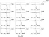
- the module set 700 shown in FIG. 17 is connected in parallel with three DC conditioners 710, 720, 730 and supplies power to the DC conditioners 710, 720, 730, respectively, with three strings 711,712,713; It is configured to have 721,722,723; 731,732,733.
- FIG. 17 shows the IV curves corresponding to them.
- the strings connected to each DC conditioner share the same operating voltage. Therefore, in FIG. 17, each IV curve is displayed for each string in the vertical direction, that is, to indicate a common operating voltage.
- the theoretical values of the DC conditioners 710, 720, and 730 (the sum of the Pmax of the modules under their control) were 4542W, 4542W, and 4542W, respectively.
- the actual power generation amounts of the DC conditioners 710, 720, and 730 were 4404W, 4404W, and 4404W, respectively. Therefore, the ratio of the operating power to the theoretical value was 96.96%, respectively.
- strings 711,721,731 the operating point is clearly deviated from the maximum output point.
- the strings 711,721,731 operate at the same potential as the operating point of each DC conditioner, and therefore operate at a position deviated from the original maximum output point of each.
- Example 11 the target power generation module set 700 was repowered using the method according to the embodiment of the present application to generate a comparative power generation module set 700R.
- FIG. 18 shows the topology of the repowered power generation module set 700R and the results of actual measurements and evaluations (IV curve). Each graph is numbered with a module in the target power generation module set 700.
- This repowering corresponds to exchanging the string 712 and the string 721, and exchanging the string 713 and the string 731.
- this repowering exchange operation is not limited to the above, and may be expressed by another exchange operation.
- each string IV curve 711R to 733R operated at each maximum output point.
- the exchange operation may consist substantially only of string-based exchanges.
- the exchange operation may include exchanges on a string basis and exchanges on a module basis.
- the string-by-string exchange does not necessarily require physical movement of the module, for example, and can be performed by exchanging the wiring. Therefore, repowering can be efficiently performed in terms of labor, cost, working time, and the like.
- the power generation characteristics of each module group may be measured or acquired.
- the module group may be composed of a plurality of modules, a plurality of strings, a plurality of DC conditioners, a plurality of AC / DC converters, a plurality of module sets, and the like.
- the module group comprises a plurality of modules, a plurality of strings, a plurality of DC conditioners, a plurality of AC / DC converters, and a plurality of modules arranged over a plurality of module sets. May be. It may be moved in units of modules or the wiring may be changed in units of modules. The topology may be changed in units of modules. The exchange operation may be performed in units of modules.
- the method of the present disclosure it is possible to perform an optional search, evaluate the power generation module set, and repower it.
- construction and repair costs can be suppressed, or the profit of the power plant can be increased.
- the technique of the present disclosure can greatly contribute to the effective use of renewable energy. Reduction from theoretical values
- knowledge-based searches may be performed.
- heuristics may be used.
- a hill climbing method a local search method may be used.
- best-first search, A *, etc. may be used.
- meta-heuristics may be used.
- simulated annealing tabu search
- genetic algorithm genetic algorithm
- ant colony optimization particle swarm optimization, and the like
- a knowledge-free search may be performed.
- tree search Upper Confidence Tree, Monte Carlo tree search
- graph search neural network
- Monte Carlo method may be performed.
- a combination of multiple search methods may be used.
- the module topology may be generated at random each time.
- FIG. 19 shows an evaluation system 1100 for a power generation module set according to an embodiment of the present disclosure.
- the system 1100 includes a central processing unit (CPU, "processor” and “computer processor” in the present specification) 1101, a cache memory 1106 arranged therein, an electronic storage unit 1102, a main memory or a memory location 1103, and a peripheral device 1104. And communication interface 1105. These components communicate with the CPU 1101 via a communication bus (solid line) such as a motherboard.
- a communication bus solid line
- the CPU 1101 may be a single-core or multi-core processor, or a plurality of processors for parallel processing.
- the cache can communicate data with the registry (not shown) of the CPU 1101 at high speed.
- the storage unit 1102 may be a data storage unit (or data repository) for storing data.
- the storage unit 1102 may be, for example, a hard disk, a magnetic tape, or the like, without limitation.
- the main memory 1103 may be, for example, a random access memory, a read-only memory, or a flash memory without limitation.
- Peripheral device 1104 may be, for example, but not limited to, other memory, data storage, and / or electronic display adapters and the like.
- the communication interface 1105 may be, for example, a network adapter or the like without limitation. The communication interface 1105 can communicate with other devices via the network 1400.
- the photovoltaic power plant (target photovoltaic power generation module set) 1200 to be evaluated is configured to have a plurality of photovoltaic power generation modules (solar cells) 1201.
- a plurality of solar modules (solar cells) 1201 are connected in a string shape, the plurality of strings are arranged, and the modules are arranged in an array shape.
- These outputs are input to the power conditioner (Power Conditioning System, PCS) 1202 via the power line.
- the PCS1202 performs a predetermined conversion of the received electric power and provides it to an external power grid (not shown).
- a power generation data measuring instrument 1203 is attached to each solar cell 1201 shown in FIG.
- the power generation data measuring instrument 1203 includes an ammeter and a voltmeter (not shown), and measures the power generation characteristics of each solar cell 1201.
- Each power generation data measuring instrument 1203 is communicably connected to the communication interface 1204.
- the target power generation module set 1200 is depicted as an existing power plant.
- the target power generation module set 1200 may be an imaginary power generation module set that does not exist.
- the power generation module set may be generated on a computer before installation or at the installation examination stage.
- the power generation module set may be generated on a computer for comparison with the subject or for other purposes.
- Information necessary for calculation such as their topology, power generation characteristics, and environmental conditions may be transmitted to the computer system 1100 via the network 1400.
- Information related to the power generation data measured by each measuring instrument 1203 is transmitted from each communication interface 1204, conveyed to the computer system 1100 via the network 1400, and received by the communication interface 1105.
- the information received by the communication interface 1105 is temporarily stored in the main memory 1103, moved to the storage 1102 at any time, and stored there.
- the input / output terminal 1301 is connected to the network 1400.
- the content of the evaluation request for the target power generation module set 1200 or the information necessary for repowering is input at this terminal 1301 and communicated to the computer system 1100 via the network 1400.
- the model number, installation information, etc. of the module used in the power plant 1200 may be sent.
- the server 1302 is connected to the network 1400.
- Information such as the name plate value of each power generation module may be stored in the server 1302. Alternatively, geographic information, solar radiation information, power generation data of other power plants, etc. of each place may be stored here.
- the computer system 1100 can acquire necessary information from the server 1302 via the network 1400.
- the computer system 1100 receives the power generation characteristic data of the target power generation module set at the communication interface 1105.
- the received data including the power generation characteristics are stored in the main memory 1103, and are moved to and stored in the storage 1102 at any time.
- the data necessary for searching the target power generation module set is stored in the main memory 1103.
- IV curve estimation> If the received IV curve is not perfect from Voc to Isc, some estimation method may be used to determine the incomplete region. A large amount of data is acquired in the vicinity of the operating point, maximum power output point, etc., and the data is often insufficient in other IV regions. A region with little data may be estimated to have a simple curve shape such as a straight line. The IV operating data may be converted to standard conditions, for example, if they are acquired under different conditions.
- the CPU 1101 quantizes the IV curve of the module.
- the IV curve obtained for a module is generally analog data.
- the value of I may be slightly different between the plurality of modules, so that it may not be possible to numerically integrate in the V direction. It is useful to quantize such data.
- Quantization is performed in at least one or both of the current direction and the voltage direction. If you want to combine the module IV curves for each string (voltage direction) to generate the string IV curve, and then combine the string IV curves for the strings connected in parallel to generate the array IV curve (current direction), the module. It is efficient to quantify the IV curve in both the current and voltage directions.
- the IV curve can be quantized by various methods. For example, the value obtained by equally dividing the Voc and Isc of the name plate value of the solar module may be used as the quantization unit.
- the CPU 1101 stores the quantized string IV curve in the cache 1106. Based on the quantized string IV curve, the CPU 1101 synthesizes the IV curve in each string in the voltage direction, that is, generates a string IV curve, and stores the generated string IV in the cache 1106. The CPU 1101 synthesizes a plurality of strings IV under the control of a DC conditioner in the current direction to generate an array IV curve. The CPU 1101 stores the array IV curve in the cache. The CPU 1101 obtains the amount of power generated by the DC conditioner from the array IV curve. The CPU 1101 obtains Pmax from the IV curve of the module under the control of the DC conditioner, and obtains the sum of the Pmax as a theoretical value.
- the CPU 1101 further obtains the ratio of the amount of generated power to the theoretical value. This ratio may be obtained as a score and output.
- the CPU 1101 outputs the module IV curve, the string IV curve, the array IV curve, the power generation amount, and the theoretical value obtained for the DC conditioner to the main memory 1103.
- the CPU 1101 sends the output information to the peripheral device 1104 and displays it from the electronic display thereof.
- the CPU 1101 transmits the output information to the outside from the communication interface 1105, sends it to the input / output terminal 1301 via the network 1400, and provides the result to the customer there, or sends it to the server 1302 and stores it there. You may.
- the CPU 1101 reads the search algorithm from the storage unit 1102 and executes it.
- the CPU 1101 uses a search algorithm to transform the topology of the target power generation module set, that is, to perform an operation of replacing a predetermined or arbitrary module, thereby generating an imaginary power generation module set.
- the power generation module set obtained as a non-final intermediate result may be referred to as a comparative power generation module set.
- a string IV curve, an array IV curve, a power generation amount, a theoretical value, etc. are generated.
- the module IV curve has already been generated and does not need to be recalculated in the evaluation of the comparative generation module set.
- the cache 1106 is described as a physical existence, but the present invention is not limited to this. Depending on the language environment, it is possible to control the cache object so that it is not placed in the cache memory.
- the cache object may be placed in a memory other than the cache.
- the calculation result of the unit having a high probability of not changing in the exchange operation may be stored in the cache 1106. Then, the calculation result of the unit that does not actually change as a result of performing the exchange operation can be called from the cache 1106 and used for the calculation after the exchange operation. In this way, the cache 1106 may be used to make a memo of a part or all of the calculation result.
- the lead wires of the strings connecting the power generation modules, the parallel connection relationship of a plurality of strings, etc. were not changed by repowering.
- the so-called topology such as the frame and the connection mode of the cable was not changed.
- the locations where the modules were placed were fixed, there was no change in the connectivity between those locations, only the modules were moved.
- the present disclosure may change the position and connection relationship for these as well. That is, the entire power generation module and wiring in the power generation module set, that is, the topology may be changed.
- A001 A method of evaluating a power generation module set with multiple modules. To provide the power generation characteristics of each of the plurality of modules, A method comprising calculating a score for the power generation module set, defined as a function of the power generation characteristics obtained from the plurality of modules. A011 The above method is applied to a plurality of power generation module sets. Comparing the plurality of said scores of the plurality of power generation module sets, The method according to embodiment A001. A012 The power generation module set includes a plurality of power generation module sets. Calculating the score comprises calculating a plurality of the scores for the plurality of power generation module sets. The method according to embodiment A001.
- A051 A method of evaluating a set of power generation modules, each containing at least one (s) of strings configured by connecting at least one (s) of power generation modules in series. To provide the power generation characteristics of each of the plurality of power generation modules, A method comprising calculating a score for the power generation module set, defined as a function of the power generation characteristics obtained from the power generation modules.
- A101 A method of evaluating a power generation module set with multiple modules. To provide the power generation characteristics (eg IV curve) of each of the multiple modules of the target power generation module set. To calculate the score (first score) for the target power generation module set, which is defined as a function of the power generation characteristics of the plurality of modules.
- A121 Providing the power generation characteristics of each of the plurality of modules of the target power generation module set comprises measuring the power generation characteristics in the plurality of modules.
- the power generation characteristics include power generation IV curve characteristics.
- A123 Measuring the power generation characteristic comprises acquiring a partial measurement at at least one of the current and voltage of the power generation IV curve characteristic. The method according to embodiment A122.
- A124 Providing the power generation characteristics comprises obtaining the power generation IV curve characteristics for substantially the entire range of currents and voltages based on the partially acquired currents and voltages. The method according to embodiment A123.
- A125 Providing the power generation characteristic comprises performing a correction process on the power generation IV curve characteristic acquired by measurement. The method according to any one of embodiments A121 to A124.
- A126 Providing the power generation characteristic provides the converted power generation IV characteristic by converting the power generation IV curve characteristic acquired by measurement into a standard condition (STC) based on at least one of a solar radiation condition and a temperature. Prepare to do, The method according to any one of embodiments A121 to A125.
- STC standard condition
- A127 To provide the power generation characteristics is to provide the individual modules with the power generation IV curve characteristics obtained by measurement based on at least one of the solar radiation conditions and the temperature received by the individual modules. STC) and provided with the converted power generation IV characteristics.
- A128 Measuring the power generation characteristics comprises making measurements by the PPPC method.
- A131 The power generation module set comprises a DC conditioner to which one or more strings are connected.
- A132 The power generation module set comprises a plurality of DC conditioners.
- the DC conditioner includes a plurality of DC conditioners.
- A141 Calculating the score comprises synthesizing the power generation characteristics of a plurality of modules serially connected to the string for each string to generate the power generation characteristics of each string.
- A142 Calculating the score comprises quantizing the power generation characteristics of each module at least one of voltage and current before synthesizing the power generation characteristics of the plurality of modules.
- A143 The score is the maximum output (Pmax) of the string power generation characteristic.
- Pmax maximum output
- A151 Calculating the score is For each of the strings connected to the DC conditioner, the power generation characteristics of a plurality of modules connected in series to the string are combined to generate the string power generation characteristics. To generate an array power generation characteristic by synthesizing the string power generation characteristics for each string over the plurality of strings connected in parallel to the DC conditioner, and to obtain a score of the array power generation characteristics. To prepare The method according to any one of embodiments A121 to A143. A152 The score of the array power generation characteristic is the maximum output (Pmax) of the array power generation characteristic. The method according to embodiment A151. A161 Further comprising adopting one or more comparative power generation modules having the score superior to the target power generation module set. The method according to any one of embodiments A101 to A152.
- A162 Generating the comparative power generation module set comprises generating a plurality of comparative power generation module sets.
- A163 It further comprises adopting the comparative power generation module set having the best score among the plurality of comparative power generation module sets generated.
- A171 The exchange operation for the module comprises virtually exchanging some or all of the modules connected within the target power generation module set with each other to generate the comparative power generation module set.
- A172 The exchange operation for the module is a module group consisting of a part or all modules connected in the target power generation module set and a new module not connected in the target power generation module set.
- a method comprises exchanging some or all of the modules with each other to produce the comparative power generation module set.
- the method according to any one of embodiments A101 to A163.
- A173 The exchange operation for the module is represented by a combination of operations that exchange (swap) two modules with each other.
- A201a A method of evaluating a power generation module set with multiple strings, To provide the power generation characteristics of each of the plurality of strings, A method comprising calculating a score for the photovoltaic module set, defined as a function of the plurality of power generation characteristics obtained from the plurality of strings.
- A201 A method of evaluating a power generation module set with multiple strings, To provide the power generation characteristics (eg IV curve) of each of the multiple strings of the target power generation module set. To calculate the score (first score) for the target power generation module set, which is defined as a function of the power generation characteristics of the plurality of strings. Performing an exchange operation on the plurality of strings of the target power generation module set to generate a comparative power generation module set, and To calculate the score (second score) for the comparative power generation module set, How to prepare.
- A202 A method for evaluating a power generation module set having a plurality of modules.
- a method comprising calculating a score for the photovoltaic module set, defined as a function of the plurality of power generation characteristics obtained from the plurality of modules.
- A203 A method for evaluating a power generation module set having a plurality of modules. To provide the power generation characteristics (for example, IV curve) of each of the plurality of modules of the target power generation module set. To calculate the score (first score) for the target power generation module set, which is defined as a function of the power generation characteristics of the plurality of modules. Performing an exchange operation on the plurality of strings of the target power generation module set to generate a comparative power generation module set, and To calculate the score (second score) for the comparative power generation module set, How to prepare.
- the module group includes a plurality of modules.
- A206 The module group includes a plurality of modules belonging to the same string.
- A207 The plurality of modules of the module group are arranged over a plurality of strings.
- A221 Providing the power generation characteristics of each of the plurality of strings of the target power generation module set comprises measuring the power generation characteristics in the plurality of strings.
- A222 The power generation characteristics include power generation IV curve characteristics.
- A223 Measuring the power generation characteristic comprises acquiring a partial measurement at at least one of the current and voltage of the power generation IV curve characteristic.
- A224 Providing the power generation characteristics comprises obtaining the power generation IV curve characteristics for substantially the entire range of currents and voltages based on the partially acquired currents and voltages.
- A225 Providing the power generation characteristic comprises performing a correction process on the power generation IV curve characteristic acquired by measurement.
- A226 Providing the power generation characteristic provides the converted power generation IV characteristic by converting the power generation IV curve characteristic acquired by measurement into a standard condition (STC) based on at least one of a solar radiation condition and a temperature.
- STC standard condition
- A227 To provide the power generation characteristics is to provide the power generation IV curve characteristics obtained by measurement to the individual strings based on at least one of the solar radiation conditions and the temperature received by the individual modules. STC) and provided with the converted power generation IV characteristics.
- A228 Measuring the power generation characteristics comprises making measurements by the PPPC method.
- A231 The power generation module set comprises a DC conditioner to which one or more strings are connected.
- A232 The power generation module set comprises a plurality of DC conditioners.
- the DC conditioner includes a plurality of DC conditioners.
- A241 Calculating the score comprises synthesizing the power generation characteristics of a plurality of strings serially connected to the string for each series conditioner to generate the power generation characteristics of the DC conditioner.
- A242 Calculating the score comprises quantizing the power generation characteristics of each string at least one of voltage and current before synthesizing the power generation characteristics of the plurality of strings.
- A243 The score is the maximum output (Pmax) of the power generation characteristic of the string.
- A251 To calculate the score is to combine the string power generation characteristics for each string over the plurality of strings connected in parallel to the DC conditioner to generate the array power generation characteristics, and to generate the array power generation characteristics. Prepare to ask for a score, The method according to any one of embodiments A221 to A243. A252 The score of the array power generation characteristic is the maximum output (Pmax) of the array power generation characteristic. The method according to embodiment A251. A261 Further comprising adopting one or more comparative power generation modules having the score superior to the target power generation module set. The method according to any one of embodiments A201a to A252. A262 Generating the comparative power generation module set comprises generating a plurality of comparative power generation module sets.
- A263 It further comprises adopting the comparative power generation module set having the best score among the plurality of comparative power generation module sets generated.
- A271 The exchange operation for the module comprises virtually exchanging some or all strings connected within the target power generation module set with each other to generate the comparative power generation module set.
- A272 The exchange operation for the module is a module group consisting of a part or all modules connected in the target power generation module set and a new module not connected in the target power generation module set. It comprises exchanging some or all of the modules with each other to produce the comparative power generation module set.
- A273 The exchange operation for the module is represented by a combination of operations that exchange (swap) two strings with each other.
- A281 Adopting the comparative power generation module set having the best score among the plurality of comparative power generation module sets generated is to adopt. It comprises searching for a comparative power generation module set that gives a higher score than the target power generation module set.
- A282 The search includes using a hill climbing method (local search method).
- A283 The search involves using a genetic algorithm.
- the search includes using the number of modules moved or exchanged by the exchange operation as a search condition.
- A292 The number of modules moved by the replacement module includes using one or both of the number of modules in the target power generation module set and the number of new modules as a search condition.
- A293 The search includes using as an end condition the value of a parameter selected from the group consisting of the complexity of the search, the number of iterations, the time, and the score of the comparative power generation module.
- A302 Further provided to notify that the topology of the target power generation module set should be changed so as to be the adopted comparative power generation module set.
- A303 Further prepared to actually change the topology of the target power generation module set so as to be the adopted comparative power generation module set.
- A304 If no comparative PV module unit with a better score than the target PV module set is found. Output that the target power generation module should not be changed, The method according to any one of embodiments A161 to A173 and A261 to A293.
- A501 The method is a repowering method, The method according to any one of embodiments A001 to A304.
- the power generation is solar power generation.
- B001 A program for causing a computer system to execute the method according to any one of embodiments A001 to A502.
- B002 A storage medium for storing the program according to the embodiment B001.
Landscapes
- Engineering & Computer Science (AREA)
- Power Engineering (AREA)
- Supply And Distribution Of Alternating Current (AREA)
Priority Applications (1)
| Application Number | Priority Date | Filing Date | Title |
|---|---|---|---|
| JP2022571546A JPWO2022138712A1 (https=) | 2020-12-23 | 2021-12-22 |
Applications Claiming Priority (2)
| Application Number | Priority Date | Filing Date | Title |
|---|---|---|---|
| JP2020-214369 | 2020-12-23 | ||
| JP2020214369 | 2020-12-23 |
Publications (1)
| Publication Number | Publication Date |
|---|---|
| WO2022138712A1 true WO2022138712A1 (ja) | 2022-06-30 |
Family
ID=82159761
Family Applications (1)
| Application Number | Title | Priority Date | Filing Date |
|---|---|---|---|
| PCT/JP2021/047544 Ceased WO2022138712A1 (ja) | 2020-12-23 | 2021-12-22 | 発電モジュールセットを評価する方法 |
Country Status (2)
| Country | Link |
|---|---|
| JP (1) | JPWO2022138712A1 (https=) |
| WO (1) | WO2022138712A1 (https=) |
Citations (7)
| Publication number | Priority date | Publication date | Assignee | Title |
|---|---|---|---|---|
| JP2005142249A (ja) * | 2003-11-05 | 2005-06-02 | National Institute Of Advanced Industrial & Technology | 太陽光発電システムのモジュール配線設計方法 |
| US20110139184A1 (en) * | 2009-12-16 | 2011-06-16 | Nagendra Srinivas Cherukupalli | Systems, Circuits, and Methods for an Intelligent Cleaning System for an Adaptive Solar Power System |
| JP2013051293A (ja) * | 2011-08-30 | 2013-03-14 | Jx Nippon Oil & Energy Corp | 太陽光発電を最適化する演算装置、太陽光発電を最適化する方法、太陽光発電システム、及び太陽光発電シミュレーションシステム |
| JP2013080731A (ja) * | 2011-09-30 | 2013-05-02 | Toshiba Corp | Pvパネル診断装置、診断方法及び診断プログラム |
| JP2013205964A (ja) * | 2012-03-27 | 2013-10-07 | Toshiba Corp | 保守計画決定装置およびその方法 |
| KR101635919B1 (ko) * | 2014-12-31 | 2016-07-04 | 주식회사 맥사이언스 | 태양광발전시스템 스트링의 저출력 태양광 모듈 검출 시스템 및 그 방법 |
| WO2017042892A1 (ja) * | 2015-09-08 | 2017-03-16 | 株式会社東芝 | 蓄電池装置、蓄電池システム、方法及びプログラム |
-
2021
- 2021-12-22 JP JP2022571546A patent/JPWO2022138712A1/ja active Pending
- 2021-12-22 WO PCT/JP2021/047544 patent/WO2022138712A1/ja not_active Ceased
Patent Citations (7)
| Publication number | Priority date | Publication date | Assignee | Title |
|---|---|---|---|---|
| JP2005142249A (ja) * | 2003-11-05 | 2005-06-02 | National Institute Of Advanced Industrial & Technology | 太陽光発電システムのモジュール配線設計方法 |
| US20110139184A1 (en) * | 2009-12-16 | 2011-06-16 | Nagendra Srinivas Cherukupalli | Systems, Circuits, and Methods for an Intelligent Cleaning System for an Adaptive Solar Power System |
| JP2013051293A (ja) * | 2011-08-30 | 2013-03-14 | Jx Nippon Oil & Energy Corp | 太陽光発電を最適化する演算装置、太陽光発電を最適化する方法、太陽光発電システム、及び太陽光発電シミュレーションシステム |
| JP2013080731A (ja) * | 2011-09-30 | 2013-05-02 | Toshiba Corp | Pvパネル診断装置、診断方法及び診断プログラム |
| JP2013205964A (ja) * | 2012-03-27 | 2013-10-07 | Toshiba Corp | 保守計画決定装置およびその方法 |
| KR101635919B1 (ko) * | 2014-12-31 | 2016-07-04 | 주식회사 맥사이언스 | 태양광발전시스템 스트링의 저출력 태양광 모듈 검출 시스템 및 그 방법 |
| WO2017042892A1 (ja) * | 2015-09-08 | 2017-03-16 | 株式会社東芝 | 蓄電池装置、蓄電池システム、方法及びプログラム |
Also Published As
| Publication number | Publication date |
|---|---|
| JPWO2022138712A1 (https=) | 2022-06-30 |
Similar Documents
| Publication | Publication Date | Title |
|---|---|---|
| Diab et al. | Optimal sizing of hybrid solar/wind/hydroelectric pumped storage energy system in Egypt based on different meta-heuristic techniques | |
| US8620634B2 (en) | Energy resource allocation including renewable energy sources | |
| Gao et al. | Multi-objective bilevel coordinated planning of distributed generation and distribution network frame based on multiscenario technique considering timing characteristics | |
| JP7410897B2 (ja) | 発電量管理システム及び発電量管理方法 | |
| Kavuma et al. | Analysis of solar photo‐voltaic for grid integration viability in Uganda | |
| Okinda et al. | Modelling Simulation and Optimal Sizing of a Hybrid Wind, Solar PV Power System in Northern Kenya | |
| Kamal et al. | Efficient two‐layer rural electrification planning and techno‐economic assessment integrating renewable sources | |
| Ghaedi et al. | Spinning reserve scheduling in power systems containing wind and solar generations | |
| WO2022138712A1 (ja) | 発電モジュールセットを評価する方法 | |
| Diop et al. | Wind Power Forecasting Using Machine Learning Algorithms | |
| Zhang et al. | Probabilistic Chronological Production Simulation‐Based Coordinated Dispatching for Cascaded Hydro‐PV‐PSH Combined Power Generation System | |
| Arabzadeh Saheli et al. | Feasibility study of a hybrid grid‐tied photovoltaic‐wave system on the shores of Persian Gulf | |
| Karki et al. | Impact of renewable energy unit availability on power system adequacy | |
| CN116562137A (zh) | 基于多物理量耦合的光伏阵列输出功率的计算方法及装置 | |
| Khasanov et al. | Photovoltaic-based Distributed Generation Allocation in Distribution Network for Energy Loss Minimization | |
| Xu et al. | Power forecasting of photovoltaic generation based on multiple linear regression method with real-time correction term | |
| CA2710905C (en) | Energy resource allocation including renewable energy sources | |
| Barancsuk et al. | Analysis of state estimation accuracy in distribution networks using pseudo-measurement selection and real measurement incorporation | |
| KR102591679B1 (ko) | 경제급전을 위한 발전량 결정 장치 및 방법 | |
| Wert et al. | Accounting for Renewable Resource Droughts in Energy Infrastructure Planning for California, Part II: Nodal Capacity Expansion Planning | |
| Suwarno et al. | Solar power forecasting model as a renewable generation source on virtual power plants | |
| Jamahori et al. | ANALYSIS OF NON-OPTIMAL PV SIZING AND PLACEMENT IN DISTRIBUTION NETWORKS WITH COMMERCIAL, INDUSTRIAL, AND RESIDENTIAL LOADS | |
| Alferidi et al. | Adequacy considerations in concentrated solar thermal integrated electric power system | |
| Sandherr et al. | Modeling analysis for solar/wind-powered microgrid on Tangier Island | |
| Özbek et al. | Assessing the Viability of High-Capacity Photovoltaic Power Plants in Diverse Climatic Zones: A Technical, Economic, and Environmental Analysis |
Legal Events
| Date | Code | Title | Description |
|---|---|---|---|
| 121 | Ep: the epo has been informed by wipo that ep was designated in this application |
Ref document number: 21910852 Country of ref document: EP Kind code of ref document: A1 |
|
| ENP | Entry into the national phase |
Ref document number: 2022571546 Country of ref document: JP Kind code of ref document: A |
|
| NENP | Non-entry into the national phase |
Ref country code: DE |
|
| 32PN | Ep: public notification in the ep bulletin as address of the adressee cannot be established |
Free format text: NOTING OF LOSS OF RIGHTS PURSUANT TO RULE 112(1) EPC (EPO FORM 1205 DATED 27/09/2023) |
|
| 122 | Ep: pct application non-entry in european phase |
Ref document number: 21910852 Country of ref document: EP Kind code of ref document: A1 |