WO2022138352A1 - 自動操縦ロボットの制御装置及び制御方法 - Google Patents
自動操縦ロボットの制御装置及び制御方法 Download PDFInfo
- Publication number
- WO2022138352A1 WO2022138352A1 PCT/JP2021/046168 JP2021046168W WO2022138352A1 WO 2022138352 A1 WO2022138352 A1 WO 2022138352A1 JP 2021046168 W JP2021046168 W JP 2021046168W WO 2022138352 A1 WO2022138352 A1 WO 2022138352A1
- Authority
- WO
- WIPO (PCT)
- Prior art keywords
- vehicle
- sub
- learning
- policy
- measures
- Prior art date
- Legal status (The legal status is an assumption and is not a legal conclusion. Google has not performed a legal analysis and makes no representation as to the accuracy of the status listed.)
- Ceased
Links
Images




Classifications
-
- G—PHYSICS
- G01—MEASURING; TESTING
- G01M—TESTING STATIC OR DYNAMIC BALANCE OF MACHINES OR STRUCTURES; TESTING OF STRUCTURES OR APPARATUS, NOT OTHERWISE PROVIDED FOR
- G01M17/00—Testing of vehicles
- G01M17/007—Wheeled or endless-tracked vehicles
Definitions
- the present invention relates to a control device and a control method for an autopilot robot.
- the fuel consumption and exhaust gas when the vehicle is driven according to a specific driving pattern (hereinafter referred to as a mode) specified in a country or region are measured. It is required to perform a test and display the test results.
- the mode can be represented by, for example, a graph of the relationship between the time from the start of traveling and the vehicle speed to be reached. The speed to be reached is sometimes referred to as the commanded vehicle speed in terms of the command given to the vehicle regarding the speed to be achieved.
- the test for measuring fuel consumption and exhaust gas is performed by placing the vehicle on the chassis dynamometer and driving the vehicle according to the mode by the automatic control robot (drive robot (registered trademark)) installed in the vehicle.
- drive robot registered trademark
- the commanded vehicle speed has a margin of error, and if the vehicle speed falls outside the margin of error, the test becomes invalid. Therefore, the control of the autopilot robot is required to have high followability to the command vehicle speed, and the autopilot robot is controlled by the learning model learned by reinforcement learning.
- Patent Document 1 which is an example of the prior art, discloses a control device and a control method for an autopilot robot controlled by a learning model learned by reinforcement learning.
- a control method that is, a measure
- an evaluation value becomes large which is called a reward
- the controlled object may be damaged by forcing the controlled object to behave with a large load, and the learning takes time.
- it is particularly required to reduce the time (cost) spent on the learning time during the test on an actual vehicle using the drive robot, that is, the actual test. It is effective to use a simulator for these problems.
- the policy acquired by reinforcement learning is effective only for a specific controlled object, and in order to apply the policy to a controlled object having different characteristics, additional learning according to the characteristic of the controlled object is performed. It takes. Therefore, there is a problem that the effect of reducing the learning cost by using the simulator is small.
- the present invention has been made in view of the above, and an object thereof is to shorten the learning time at the time of an actual test.
- One of the present inventions for solving the above-mentioned problems and achieving the object is to control an autopilot robot mounted on a vehicle to drive the vehicle so that the vehicle travels according to a specified command vehicle speed. It is a control device of a control robot and includes a calculation unit that outputs vehicle operations by learning based on an enhanced learning algorithm. It is a control device of an autopilot robot obtained by the MLSH method, which is performed by a policy having a hierarchical structure composed of a main policy in which the plurality of sub-measures are mixed and specialized for a target vehicle.
- one of the present inventions is a control method for the autopilot robot, which controls the autopilot robot mounted on the vehicle to drive the vehicle so that the vehicle travels according to a specified command vehicle speed.
- a generalized sub-policy common to the plurality of vehicles can be obtained, and the plurality of sub-methods obtained by the MCP method or the MLSH method are mixed.
- It is a control method of an autopilot robot that includes acquiring a main policy specialized for the target vehicle.
- the learning time at the time of the actual test can be shortened.
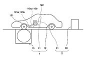
- FIG. 1 is a diagram showing an outline of a test environment using a drive robot which is an autopilot robot according to the first embodiment.
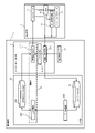
- FIG. 2 is a functional block diagram showing a test device according to the first embodiment and a control device for an autopilot robot according to the first embodiment.
- FIG. 3 is a functional block diagram showing the configuration of the reinforcement learning unit and its surroundings in the first embodiment.
- FIG. 4 is a functional block diagram showing the configuration of the vehicle operation control unit and its surroundings in the first embodiment.
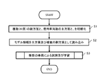
- FIG. 5 is a flowchart showing the pre-learning of the sub-measures in the first embodiment.
- FIG. 6 is a flowchart showing the process of S3 shown in FIG.
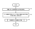
- FIG. 7 is a flowchart showing learning of the main policy of the target vehicle in the first embodiment.
- FIG. 8 is a flowchart showing the process of S13 shown in FIG. 7.
- FIG. 1 is a diagram showing an outline of a test environment using a drive robot 11 which is an autopilot robot according to the present embodiment.
- the test device 1 shown in FIG. 1 includes a drive robot 11, a vehicle 12, and a chassis dynamometer 13.
- the vehicle 12 is a vehicle under test for which performance is measured, which is arranged on the floor surface of the test environment, and includes a drive wheel 121, a driver's seat 122, and vehicle operation pedals 123a and 123b.
- the chassis dynamometer 13 is installed below the floor surface of the test environment, and is configured to drive the vehicle 12 on the chassis roller instead of on the road and measure the characteristics of the vehicle 12.
- the vehicle 12 is arranged so that the drive wheels 121, which are the front wheels of the vehicle 12, are located on the chassis dynamometer 13.
- the chassis dynamometer 13 rotates in the direction opposite to the rotation of the drive wheels 121.
- the drive robot 11 is a machine provided with actuators 110a and 110b, installed in the driver's seat 122 of the vehicle 12 instead of a human driver, and performing an operation of driving the vehicle 12.
- the actuators 110a and 110b abut on the vehicle operating pedals 123a and 123b, respectively.
- One of the vehicle operation pedals 123a and 123b is an accelerator pedal, and the other is a brake pedal.
- the drive robot 11 is controlled by the control device 2.
- the control device 2 includes a learning unit 20 and a drive robot control unit 21, and adjusts the opening degrees of the vehicle operation pedals 123a and 123b so that the vehicle 12 travels according to a specified command vehicle speed. It controls the actuators 110a and 110b. That is, the control device 2 controls the traveling of the vehicle 12 so as to follow the mode which is the defined traveling pattern by adjusting the opening degree of the vehicle operating pedals 123a and 123b of the vehicle 12. Specifically, the control device 2 controls the travel of the vehicle 12 so as to follow the command vehicle speed, which is the vehicle speed to be reached at each time, as time elapses from the start of travel.
- FIG. 2 is a functional block diagram showing a test device 1 in the present embodiment and a control device 2 for an autopilot robot according to the present embodiment.
- the test device 1 shown in FIG. 2 includes a drive robot 11, a vehicle 12, a chassis dynamometer 13, and a vehicle condition measuring unit 14.
- the vehicle state measurement unit 14 is a measurement unit that measures the state of the vehicle 12 or an externally installed measurement unit.
- the state of the vehicle 12 the operation values of the vehicle operation pedals 123a and 123b can be exemplified.
- the externally installed measuring unit a camera or an infrared sensor that measures the operating values of the vehicle operating pedals 123a and 123b can be exemplified.
- the control device 2 shown in FIG. 2 includes a learning unit 20, a drive robot control unit 21, a command vehicle speed generation unit 22, and a calculation unit 23.
- the learning unit 20 includes a learning data storage unit 201, a data molding unit 202, a reinforcement learning unit 203, and a learned model storage unit 204, and learns a vehicle model in drive robot control.
- the learning data storage unit 201 stores the learning data used for reinforcement learning in the reinforcement learning unit 203.
- the data molding unit 202 molds the learning data used in the reinforcement learning unit 203 into an appropriate data format.
- the reinforcement learning unit 203 performs reinforcement learning of the drive robot control, and is realized by the calculation unit 23.
- the trained model storage unit 204 stores the model learned by the reinforcement learning unit 203.
- the drive robot control unit 21 includes a drive state acquisition unit 211, a data molding unit 212, and a vehicle operation control unit 213, gives a control command to the drive robot 11, and acquires information on the state of the drive robot 11.
- the drive state acquisition unit 211 acquires information on the drive state of the configuration included in the test apparatus 1.
- the pedal operation detection value of the drive robot 11 can be exemplified.
- the data molding unit 212 molds the input data used by the vehicle operation control unit 213 into an appropriate data format.
- the vehicle operation control unit 213 generates a pedal operation command based on the data from the drive state acquisition unit 211, and outputs the pedal operation command to the actuators 110a and 110b of the drive robot 11 to the drive robot 11.
- the vehicle operation control unit 213 is realized by the calculation unit 23.
- the command vehicle speed generation unit 22 generates a command vehicle speed to be used as input data when inferring the drive robot control.
- FIG. 3 is a functional block diagram showing the configuration of the reinforcement learning unit 203 and its surroundings in the present embodiment.
- the reinforcement learning unit 203 shown in FIG. 3 includes a main measure 300 and sub-measures 301-1, 301-2, ..., 301-K.
- Sub-measures 301-1, 301-2, ..., 301-K are measures for pedal operation commands for input data, and are stored in the trained model storage unit 204.
- the main measure 300 is a measure of one pedal operation command as a whole in which a plurality of sub-measures are integrated, and is stored in the trained model storage unit 204.
- the main policy 300 and the sub-policy 301-1, 301-2, ..., 301-K have a hierarchical relationship in which the main policy 300 is located at a higher level, and the policy stored in the reinforcement learning unit 203 is It has a hierarchical policy structure.
- the main measure 300 the future command vehicle speed, the detected vehicle speed and the pedal operation value can be exemplified, and as the sub-measures 301-1, 301-2, ..., 301-K, the future relative vehicle speed and the pedal operation value can be exemplified. can do.
- the sub-measure is made to observe an abstract state such as the relative speed between the detection speed and the command speed
- the main measure is made to observe the non-abstract state such as the absolute speed.
- the observations handled by the sub-policy are expressed by the following equation (1)
- the observations handled by the main policy are expressed by the following equation (2). expressed.
- the pedal operation command indicates that the brake is applied, and if the decision a'is positive, the pedal operation command indicates that the accelerator is applied, and -100 ⁇ a. ' ⁇ 100. Further, the above equations (1) and (2) correspond to input data molded into an appropriate data format by the data molding unit 202 or the data molding unit 212.
- the policy is generally a probability distribution of action determination, and is a distribution defined by a distribution shape parameter output by a neural network in the framework of deep reinforcement learning.
- the neural network is learned so that the probability of outputting an action that obtains a large reward increases.
- FIG. 4 is a functional block diagram showing the configuration of the vehicle operation control unit 213 and its surroundings in the present embodiment.
- the vehicle operation control unit 213 shown in FIG. 4 includes a main policy 400 and sub-policy 401-1, 401-2, ..., 401-K.
- Sub-measures 401-1, 401-2, ..., 401-K are measures for pedal operation commands for data called from the trained model storage unit 204.
- the main measure 400 is an overall one pedal operation command measure in which a plurality of sub-measures are integrated, and is output to the drive robot 11.
- the main policy 400 and the sub-policy 401-1, 401-2, ..., 401-K have a hierarchical relationship in which the main policy 400 is located at a higher level, and the policy output to the drive robot 11 is hierarchical. It becomes a policy structure.
- the main measure 400 the future command vehicle speed, the detected vehicle speed and the pedal operation value can be exemplified, and as the sub-measures 401-1, 401-2, ..., 401-K, the future relative vehicle speed and the pedal operation value can be exemplified. can do.
- the reinforcement learning control of a drive robot aims to acquire control that causes a vehicle to be controlled to follow a commanded vehicle speed with high accuracy.
- the sub-measures obtained in the pre-learning by the simulator or the like are reused in the actual test. Measures to be controlled can be efficiently obtained.
- a plurality of sub-measures of various characteristics are acquired by a traveling task of a plurality of vehicles, and driving specialized for the vehicle is realized by a main policy learned individually for each vehicle.
- the main measure in this embodiment is obtained by the MCP (Multiplicative Compositional Policies) method.
- MCP Multiple Compositional Policies
- the influence of each sub-policy is determined in the upper policy (Gating Function), which is the main policy, and the primitive action in the state is selected in the sub-policy (Primitive), which is the sub-policy, and the action is decomposed with respect to the action space.
- the composition is performed using all the subordinate measures.
- a plurality of sub-measures are weighted, and a plurality of weighted sub-measures are mixed to obtain an overall measure.
- PPO Proximal Policy Optimization
- the sub-measures specialize in different behaviors, the behavioral variations corresponding to the states increase, and the overall performance can be improved.
- learning is performed only by the same task, so it is difficult to expand the variety of sub-policy, but as mentioned above, it is possible to diversify the sub-policy by letting the sub-policy observe the abstract state. be.
- s) is the kth sub-policy ⁇ k (a
- the partition function Z (s) is defined so that the integral of ⁇ (a
- the main strategy is created and learned individually for each vehicle. Sub-measures are shared and learned among multiple vehicle runs. As a sub-measure, a common control element in the traveling of the vehicle or a control element for each vehicle type can be exemplified.
- FIG. 5 is a flowchart showing the pre-learning of the sub-measures in the present embodiment. Since the pre-learning shown in FIG. 5 is for obtaining a sub-method, it may be performed by a simulator.
- the reinforcement learning unit 203 initializes a plurality of (K) sub-measures and a main measure for the number of vehicles used (S1).
- the vehicle operation control unit 213 reads the model information stored in the learned model storage unit 204 as the main measure and the plurality of sub-measures (S2). The model information immediately after initialization may be randomly constructed.
- the vehicle 12 on the chassis dynamometer 13 is alternately replaced to perform a test and learning by a plurality of vehicles (S3).
- the sub-policy is commonly used among a plurality of vehicles, and the main policy corresponding to each vehicle to be driven is called.
- the running completion of the command vehicle speed pattern prepared for learning running is set as one episode, and the vehicle is replaced for each episode, but the present invention is not limited to this, and the replacement of the vehicle is predetermined. You can do it at the right timing. Since the test of S3 is for obtaining an alternative measure, a plurality of vehicles 12 used in the test of S3 may be prepared by the simulator, and may not be an actual vehicle aiming at final control acquisition.
- FIG. 6 is a flowchart showing the process of S3 shown in FIG.
- the vehicle operation control unit 213 creates a pedal operation command using the command vehicle speed and the drive state (S31).
- the drive state acquisition unit 211 acquires travel data based on the pedal operation command (S32), combines the acquired travel data with the command vehicle speed from the command vehicle speed generation unit 22, and learn data storage unit 201 and the vehicle operation control unit.
- Send to 213 S33
- the learning data storage unit 201 stores commanded vehicle speed and travel data (S34). This test is run until the end of the episode, as described above.
- the reinforcement learning unit 203 learns the main policy 300 corresponding to the vehicle and the common sub-measures 301-1, 301-2, ..., 301-K (S35).
- the reinforcement learning unit 203 learns by the above-mentioned MCP method.
- the reward design is such that the smaller the error between the command vehicle speed and the detected vehicle speed, the larger the reward can be obtained.
- a test in which driving and learning are repeated is performed based on the model information obtained by learning, and a generalized sub-measure common to a plurality of vehicles and a main measure corresponding to each vehicle are used. , Will be acquired.
- FIG. 7 is a flowchart showing learning of the main policy of the target vehicle in the present embodiment.
- the learning of the main policy shown in FIG. 7 is performed using an actual vehicle after the pre-learning shown in FIG.
- the learning using the actual vehicle that is, the learning at the time of the actual test can be shortened as compared with the conventional one. ..
- the reinforcement learning unit 203 initializes the main policy of the vehicle used for the test (S11).
- the vehicle operation control unit 213 reads the model information stored in the trained model storage unit 204 as the initialized main measure and the plurality of pre-learned sub-measures (S12).
- the main policy of the model information immediately after initialization may be constructed at random.
- the vehicle 12 which is the target vehicle on the chassis dynamometer 13 is tested and learned (S13).
- FIG. 8 is a flowchart showing the process of S13 shown in FIG. 7.
- the vehicle operation control unit 213 creates a pedal operation command using the command vehicle speed and the drive state (S131).
- the drive state acquisition unit 211 acquires travel data based on the pedal operation command (S132), combines the acquired travel data with the command vehicle speed from the command vehicle speed generation unit 22, and learn data storage unit 201 and the vehicle operation control unit.
- Send to 213 (S133).
- the learning data storage unit 201 stores commanded vehicle speed and travel data (S134). This test runs until the end of the episode, but is not limited to this.
- the reinforcement learning unit 203 learns the main policy 300 corresponding to the vehicle (S135). This learning is performed until the test of the target vehicle is completed.
- the model information including the learned main policy is used to perform a test in which running and learning are repeated, the main policy corresponding to the target vehicle is acquired, and the target vehicle can be controlled.
- the reinforcement learning unit 203 and the vehicle operation control unit 213 are realized by the calculation unit 23 of the control device 2. That is, the control device 2 of the autopilot robot according to the present embodiment includes a calculation unit 23 that outputs the operation of the vehicle by learning based on the reinforcement learning algorithm.
- the operation of the vehicle is a hierarchy composed of a plurality of sub-measures common among the plurality of vehicles and a main measure obtained by the MCP method in which the plurality of sub-measures are mixed and specialized for the target vehicle. It is done by structural measures.
- a hierarchical policy consisting of a common sub-policy among multiple vehicles obtained by prior learning and a main policy that combines multiple sub-policy and specializes in the target vehicle.
- the expressive ability of the policy is improved and the control performance is improved.
- the sub-policy common to a plurality of vehicles is obtained by prior learning and the main policy may be learned in the actual test for the actual vehicle, the learning time at the time of the actual test can be shortened.
- the control device 2 of the autopilot robot includes a calculation unit that outputs the operation of the vehicle by learning based on the reinforcement learning algorithm.
- the operation of the vehicle is a hierarchy composed of a plurality of sub-measures common among the plurality of vehicles and a main measure obtained by the MLSH method in which the plurality of sub-measures are mixed and specialized for the target vehicle. It is a control device for an autopilot robot that is operated by structural measures.
- the lower policy to be used is selected in the upper policy (Master Policy), which is the main policy, and the control policy, which is the action in the state, is selected in the lower policy (Sub Policy), which is the sub policy. It is decomposed and one subordinate measure to be used at each time is selected.
- Master Policy which is the main policy
- Sub Policy which is the sub policy. It is decomposed and one subordinate measure to be used at each time is selected.
- the weighting of the sub-measures is determined according to the observation state from moment to moment, whereas in the MLSH method in the present embodiment, any one of the sub-measures is selected.
- the basic elements of actions such as pedal operation are easily expressed as sub-measures
- the elements peculiar to the controlled task are as sub-measures. It becomes easier to express. According to the present embodiment, for example, when the characteristics of the task change with time, it is possible to acquire control to follow the command vehicle speed with high accuracy.
- Test equipment 11 Drive robot 110a, 110b Actuator 12 Vehicle 121 Drive wheel 122 Driver's seat 123a, 123b Vehicle operation pedal 13 Chassis dynamometer 14 Vehicle condition measurement unit 2 Control device 20 Learning unit 201 Learning data storage unit 202 Data molding unit 203 Strengthening Learning unit 204 Learned model storage unit 21 Drive robot control unit 211 Drive state acquisition unit 212 Data molding unit 213 Vehicle operation control unit 22 Command vehicle speed generation unit 23 Calculation unit 300, 400 Main measures 301-1, 301-2, ..., 301-K, 401-1, 401-2, ..., 401-K Sub-measures
Landscapes
- Physics & Mathematics (AREA)
- General Physics & Mathematics (AREA)
- Feedback Control In General (AREA)
- Manipulator (AREA)
Abstract
自動操縦ロボットの制御装置及び制御方法の実試験時の学習時間を短くすることを目的として、車両に搭載されて該車両を走行させる自動操縦ロボットを該車両が規定された指令車速に従って走行するように制御する、該自動操縦ロボットの制御装置が、強化学習アルゴリズムに基づいた学習により車両の操作を出力する演算部を備え、該車両の操作は、複数の車両間で共通の複数の副方策と、MCP法又はMLSH法によって得られる、前記複数の副方策が混合されて対象車両に特化された主方策と、により構成される階層構造の方策により行われる。
Description
本発明は、自動操縦ロボットの制御装置及び制御方法に関する。
一般に、普通自動車等の車両を製造して販売する際には、国又は地域において規定された、特定の走行パターン(以下、モードという)により車両を走行させた際の燃費及び排出ガスを測定する試験を行い、この試験結果を表示することが求められる。
モードは、例えば、走行開始からの時間と、到達すべき車速との関係のグラフにより表わすことが可能である。
到達すべき車速は、車両に与えられる達成すべき速度に関する指令という観点で、指令車速と呼ばれることがある。
燃費及び排出ガスを測定する試験は、シャシーダイナモメータ上に車両を載置し、車両に設置された自動操縦ロボット(ドライブロボット(登録商標))により、モードに従って車両を運転させることにより行われる。
指令車速には許容誤差範囲が規定されており、車速が許容誤差範囲外になると、その試験は無効となる。
そのため、自動操縦ロボットの制御には指令車速への高い追従性が求められ、自動操縦ロボットは、強化学習により学習された学習モデルにより制御される。
モードは、例えば、走行開始からの時間と、到達すべき車速との関係のグラフにより表わすことが可能である。
到達すべき車速は、車両に与えられる達成すべき速度に関する指令という観点で、指令車速と呼ばれることがある。
燃費及び排出ガスを測定する試験は、シャシーダイナモメータ上に車両を載置し、車両に設置された自動操縦ロボット(ドライブロボット(登録商標))により、モードに従って車両を運転させることにより行われる。
指令車速には許容誤差範囲が規定されており、車速が許容誤差範囲外になると、その試験は無効となる。
そのため、自動操縦ロボットの制御には指令車速への高い追従性が求められ、自動操縦ロボットは、強化学習により学習された学習モデルにより制御される。
従来技術の一例である特許文献1には、強化学習により学習された学習モデルにより制御される自動操縦ロボットの制御装置及び制御方法が開示されている。
特許文献1に開示された技術では、制御対象を試行錯誤的に制御させつつ、報酬と呼ばれる評価値が大きくなる制御方法(すなわち方策)を獲得(すなわち学習)する。
ここで、試行錯誤的な学習では、制御対象に負荷の大きい挙動を強いることにより制御対象が破損し得、また、学習に時間を要する。
実用上は、ドライブロボットを用いた実際の車両に対する試験、すなわち実試験時の学習時間に費やす時間(コスト)を小さくすることが特に求められている。
これらの問題点に対しては、シミュレータを用いることが有効である。
特許文献1に開示された技術では、制御対象を試行錯誤的に制御させつつ、報酬と呼ばれる評価値が大きくなる制御方法(すなわち方策)を獲得(すなわち学習)する。
ここで、試行錯誤的な学習では、制御対象に負荷の大きい挙動を強いることにより制御対象が破損し得、また、学習に時間を要する。
実用上は、ドライブロボットを用いた実際の車両に対する試験、すなわち実試験時の学習時間に費やす時間(コスト)を小さくすることが特に求められている。
これらの問題点に対しては、シミュレータを用いることが有効である。
しかしながら、上記の従来技術では、強化学習によって獲得される方策は特定の制御対象のみに有効であり、特性が異なる制御対象への方策の適用には、その制御対象の特性に沿った追加学習を要する。
そのため、シミュレータを用いることによる学習コストの低減効果が小さい、という問題があった。
そのため、シミュレータを用いることによる学習コストの低減効果が小さい、という問題があった。
本発明は、上記に鑑みてなされたものであって、実試験時の学習時間を短くすることを目的とする。
上述の課題を解決して目的を達成する本発明の一つは、車両に搭載されて該車両を走行させる自動操縦ロボットを該車両が規定された指令車速に従って走行するように制御する、該自動操縦ロボットの制御装置であって、強化学習アルゴリズムに基づいた学習により車両の操作を出力する演算部を備え、該車両の操作は、複数の車両間で共通の複数の副方策と、MCP法又はMLSH法によって得られる、前記複数の副方策が混合されて対象車両に特化された主方策と、により構成される階層構造の方策により行われる自動操縦ロボットの制御装置である。
又は、本発明の一つは、車両に搭載されて該車両を走行させる自動操縦ロボットを該車両が規定された指令車速に従って走行するように制御する、該自動操縦ロボットの制御方法であって、複数の車両について走行と学習とを繰り返す試験を行うことで、複数の車両に共通の汎化的な副方策を獲得すること、MCP法又はMLSH法によって得られる、前記複数の副方策が混合されて対象車両に特化された主方策を獲得することを含む自動操縦ロボットの制御方法である。
本発明によれば、実試験時の学習時間を短くすることができる。
以下、添付図面を参照して、本発明を実施するための形態について説明する。
ただし、本発明は、以下の実施形態の記載によって限定解釈されるものではない。
ただし、本発明は、以下の実施形態の記載によって限定解釈されるものではない。
(実施形態1)
図1は、本実施形態に係る自動操縦ロボットであるドライブロボット11を用いた試験環境の概要を示す図である。
図1に示す試験装置1は、ドライブロボット11と、車両12と、シャシーダイナモメータ13と、を備える。
車両12は、試験環境の床面上に配置された、性能が計測される被試験車両であり、駆動輪121と、運転席122と、車両操作ペダル123a,123bと、を備える。
シャシーダイナモメータ13は、試験環境の床面の下方に設置され、路上に代えてシャシローラ上で車両12を走行させ、車両12の特性を計測するための構成である。
車両12は、車両12の前輪である駆動輪121がシャシーダイナモメータ13の上に位置するように配置されている。
駆動輪121が回転する際には、シャシーダイナモメータ13は、駆動輪121の回転の反対方向に回転する。
図1は、本実施形態に係る自動操縦ロボットであるドライブロボット11を用いた試験環境の概要を示す図である。
図1に示す試験装置1は、ドライブロボット11と、車両12と、シャシーダイナモメータ13と、を備える。
車両12は、試験環境の床面上に配置された、性能が計測される被試験車両であり、駆動輪121と、運転席122と、車両操作ペダル123a,123bと、を備える。
シャシーダイナモメータ13は、試験環境の床面の下方に設置され、路上に代えてシャシローラ上で車両12を走行させ、車両12の特性を計測するための構成である。
車両12は、車両12の前輪である駆動輪121がシャシーダイナモメータ13の上に位置するように配置されている。
駆動輪121が回転する際には、シャシーダイナモメータ13は、駆動輪121の回転の反対方向に回転する。
ドライブロボット11は、アクチュエータ110a,110bを備え、人間のドライバーに代えて車両12の運転席122に設置され、車両12を走行させる動作を行う機械である。
アクチュエータ110a,110bは、各々、車両操作ペダル123a,123bに当接する。
車両操作ペダル123a,123bの一方はアクセルペダルであり、他方はブレーキペダルである。
アクチュエータ110a,110bは、各々、車両操作ペダル123a,123bに当接する。
車両操作ペダル123a,123bの一方はアクセルペダルであり、他方はブレーキペダルである。
ドライブロボット11は、制御装置2によって制御される。
制御装置2は、学習部20と、ドライブロボット制御部21と、を備え、車両12が規定された指令車速に従って走行するように車両操作ペダル123a,123bの開度を調整し、ドライブロボット11のアクチュエータ110a,110bを制御する。
すなわち、制御装置2は、車両12の車両操作ペダル123a,123bの開度を調整することで、規定された走行パターンであるモードに従うように、車両12の走行を制御する。
詳細には、制御装置2は、走行開始から時間が経過するに従って、各時刻に到達すべき車速である指令車速に従うように、車両12の走行を制御する。
制御装置2は、学習部20と、ドライブロボット制御部21と、を備え、車両12が規定された指令車速に従って走行するように車両操作ペダル123a,123bの開度を調整し、ドライブロボット11のアクチュエータ110a,110bを制御する。
すなわち、制御装置2は、車両12の車両操作ペダル123a,123bの開度を調整することで、規定された走行パターンであるモードに従うように、車両12の走行を制御する。
詳細には、制御装置2は、走行開始から時間が経過するに従って、各時刻に到達すべき車速である指令車速に従うように、車両12の走行を制御する。
図2は、本実施形態における試験装置1と、本実施形態に係る自動操縦ロボットの制御装置2と、を示す機能ブロック図である。
図2に示す試験装置1は、ドライブロボット11と、車両12と、シャシーダイナモメータ13と、車両状態計測部14と、を備える。
車両状態計測部14は、車両12の状態を計測する計測部又は外的に設置された計測部である。
ここで、車両12の状態としては、車両操作ペダル123a,123bの操作値を例示することができる。
ここで、外的に設置された計測部としては、車両操作ペダル123a,123bの操作値を計測するカメラ又は赤外線センサ等を例示することができる。
図2に示す試験装置1は、ドライブロボット11と、車両12と、シャシーダイナモメータ13と、車両状態計測部14と、を備える。
車両状態計測部14は、車両12の状態を計測する計測部又は外的に設置された計測部である。
ここで、車両12の状態としては、車両操作ペダル123a,123bの操作値を例示することができる。
ここで、外的に設置された計測部としては、車両操作ペダル123a,123bの操作値を計測するカメラ又は赤外線センサ等を例示することができる。
図2に示す制御装置2は、学習部20と、ドライブロボット制御部21と、指令車速生成部22と、演算部23と、を備える。
学習部20は、学習データ記憶部201と、データ成型部202と、強化学習部203と、学習済みモデル記憶部204と、を備え、ドライブロボット制御における車両モデルの学習を行う。
学習データ記憶部201は、強化学習部203における強化学習に用いる学習データを記憶する。
データ成型部202は、強化学習部203で使用される学習データを適切なデータ形式に成型する。
強化学習部203は、ドライブロボット制御の強化学習を行い、演算部23により実現される。
学習済みモデル記憶部204は、強化学習部203で学習したモデルを記憶する。
学習部20は、学習データ記憶部201と、データ成型部202と、強化学習部203と、学習済みモデル記憶部204と、を備え、ドライブロボット制御における車両モデルの学習を行う。
学習データ記憶部201は、強化学習部203における強化学習に用いる学習データを記憶する。
データ成型部202は、強化学習部203で使用される学習データを適切なデータ形式に成型する。
強化学習部203は、ドライブロボット制御の強化学習を行い、演算部23により実現される。
学習済みモデル記憶部204は、強化学習部203で学習したモデルを記憶する。
ドライブロボット制御部21は、駆動状態取得部211と、データ成型部212と、車両操作制御部213と、を備え、ドライブロボット11に制御指令を与え、ドライブロボット11の状態の情報を取得する。
駆動状態取得部211は、試験装置1に含まれる構成の駆動状態の情報を取得する。
ここで、試験装置1に含まれる構成の駆動状態としては、ドライブロボット11のペダル操作検出値を例示することができる。
データ成型部212は、車両操作制御部213で使用される入力データを適切なデータ形式に成型する。
車両操作制御部213は、駆動状態取得部211からのデータに基づいてペダル操作指令を生成し、ドライブロボット11のアクチュエータ110a,110bへのペダル操作指令をドライブロボット11に出力する。
車両操作制御部213は演算部23により実現される。
駆動状態取得部211は、試験装置1に含まれる構成の駆動状態の情報を取得する。
ここで、試験装置1に含まれる構成の駆動状態としては、ドライブロボット11のペダル操作検出値を例示することができる。
データ成型部212は、車両操作制御部213で使用される入力データを適切なデータ形式に成型する。
車両操作制御部213は、駆動状態取得部211からのデータに基づいてペダル操作指令を生成し、ドライブロボット11のアクチュエータ110a,110bへのペダル操作指令をドライブロボット11に出力する。
車両操作制御部213は演算部23により実現される。
指令車速生成部22は、ドライブロボット制御の推論を行う際に、入力データとして使用する指令車速を生成する。
図3は、本実施形態における強化学習部203及び周辺の構成を示す機能ブロック図である。
図3に示す強化学習部203は、主方策300と、副方策301-1,301-2,…,301-Kと、を含む。
副方策301-1,301-2,…,301-Kは、入力データに対するペダル操作指令の方策であり、学習済みモデル記憶部204に記憶される。
主方策300は、複数の副方策が統合された、全体的な1つのペダル操作指令の方策であり、学習済みモデル記憶部204に記憶される。
主方策300と副方策301-1,301-2,…,301-Kとは、主方策300が上位に位置する階層的な関係性を有し、強化学習部203に記憶された方策は、階層的な方策構造となる。
主方策300としては、将来指令車速、検出車速及びペダル操作値を例示することができ、副方策301-1,301-2,…,301-Kとしては、将来相対車速及びペダル操作値を例示することができる。
図3に示す強化学習部203は、主方策300と、副方策301-1,301-2,…,301-Kと、を含む。
副方策301-1,301-2,…,301-Kは、入力データに対するペダル操作指令の方策であり、学習済みモデル記憶部204に記憶される。
主方策300は、複数の副方策が統合された、全体的な1つのペダル操作指令の方策であり、学習済みモデル記憶部204に記憶される。
主方策300と副方策301-1,301-2,…,301-Kとは、主方策300が上位に位置する階層的な関係性を有し、強化学習部203に記憶された方策は、階層的な方策構造となる。
主方策300としては、将来指令車速、検出車速及びペダル操作値を例示することができ、副方策301-1,301-2,…,301-Kとしては、将来相対車速及びペダル操作値を例示することができる。
本実施形態において、副方策には検出速度と指令速度との相対速度のような抽象状態を観測させ、主方策には絶対速度のような抽象化していない状態を観測させる。
ここで、検出速度v_t、指令速度v~_t及び意思決定a’を用いると、副方策で扱う観測は下記の式(1)で表され、主方策で扱う観測は下記の式(2)で表される。
ここで、検出速度v_t、指令速度v~_t及び意思決定a’を用いると、副方策で扱う観測は下記の式(1)で表され、主方策で扱う観測は下記の式(2)で表される。


なお、意思決定a’が負である場合にはペダル操作指令はブレーキをかけることを表し、意思決定a’が正である場合にはペダル操作指令はアクセルをかけることを表し、-100≦a’≦100である。
また、上記の式(1),(2)は、データ成型部202又はデータ成型部212によって適切なデータ形式に成型された入力データに相当する。
また、上記の式(1),(2)は、データ成型部202又はデータ成型部212によって適切なデータ形式に成型された入力データに相当する。
なお、ここで、方策は、一般に行動決定の確率分布であり、深層強化学習の枠組みではニューラルネットワークによって出力された分布形状パラメータで規定される分布である。
強化学習部203においては、大きな報酬が得られる行動を出力する確率が大きくなるように、ニューラルネットワークが学習される。
強化学習部203においては、大きな報酬が得られる行動を出力する確率が大きくなるように、ニューラルネットワークが学習される。
図4は、本実施形態における車両操作制御部213及び周辺の構成を示す機能ブロック図である。
図4に示す車両操作制御部213は、主方策400と、副方策401-1,401-2,…,401-Kと、を含む。
副方策401-1,401-2,…,401-Kは、学習済みモデル記憶部204から呼び出されるデータに対するペダル操作指令の方策である。
主方策400は、複数の副方策が統合された、全体的な1つのペダル操作指令の方策であり、ドライブロボット11に出力される。
主方策400と副方策401-1,401-2,…,401-Kとは、主方策400が上位に位置する階層的な関係性を有し、ドライブロボット11に出力される方策は、階層的な方策構造となる。
主方策400としては、将来指令車速、検出車速及びペダル操作値を例示することができ、副方策401-1,401-2,…,401-Kとしては、将来相対車速及びペダル操作値を例示することができる。
図4に示す車両操作制御部213は、主方策400と、副方策401-1,401-2,…,401-Kと、を含む。
副方策401-1,401-2,…,401-Kは、学習済みモデル記憶部204から呼び出されるデータに対するペダル操作指令の方策である。
主方策400は、複数の副方策が統合された、全体的な1つのペダル操作指令の方策であり、ドライブロボット11に出力される。
主方策400と副方策401-1,401-2,…,401-Kとは、主方策400が上位に位置する階層的な関係性を有し、ドライブロボット11に出力される方策は、階層的な方策構造となる。
主方策400としては、将来指令車速、検出車速及びペダル操作値を例示することができ、副方策401-1,401-2,…,401-Kとしては、将来相対車速及びペダル操作値を例示することができる。
次に、本実施形態において行われる学習について説明する。
一般に、ドライブロボットの強化学習制御は、制御対象の車両を指令車速に沿って高精度に追従させる制御の獲得を目指す。
本実施形態においては、ドライブロボットの強化学習制御における実際の車両に対する実試験における学習の効率化を目的とし、シミュレータ等により事前学習において得られた副方策を実試験に再利用することで、新たな制御対象の方策が効率的に得られる。
本実施形態によれば、複数の車両の走行タスクにより様々な特質の複数の副方策が獲得され、車両ごとに個別に学習された主方策によって該車両に特化した走行が実現される。
一般に、ドライブロボットの強化学習制御は、制御対象の車両を指令車速に沿って高精度に追従させる制御の獲得を目指す。
本実施形態においては、ドライブロボットの強化学習制御における実際の車両に対する実試験における学習の効率化を目的とし、シミュレータ等により事前学習において得られた副方策を実試験に再利用することで、新たな制御対象の方策が効率的に得られる。
本実施形態によれば、複数の車両の走行タスクにより様々な特質の複数の副方策が獲得され、車両ごとに個別に学習された主方策によって該車両に特化した走行が実現される。
本実施形態における主方策は、MCP(Multiplicative Compositional Policies)法によって得られる。
MCP法においては、主方策である上位方策(Gating Function)では各下位方策の影響度が決定され、副方策である下位方策(Primitive)では状態におけるプリミティブ行動が選択され、行動が行動空間に関して分解され、各時刻で全ての下位方策を使用して合成が行われる。
MCP法によれば、複数の副方策に重み付けが行われ、重み付けが行われた複数の副方策が混合されることで全体の方策が得られる。
また、強化学習制御における強化学習アルゴリズムとしては、例えばPPO(Proximal Policy Optimization)を用いることができるが、これに限定されるものではない。
MCP法においては、主方策である上位方策(Gating Function)では各下位方策の影響度が決定され、副方策である下位方策(Primitive)では状態におけるプリミティブ行動が選択され、行動が行動空間に関して分解され、各時刻で全ての下位方策を使用して合成が行われる。
MCP法によれば、複数の副方策に重み付けが行われ、重み付けが行われた複数の副方策が混合されることで全体の方策が得られる。
また、強化学習制御における強化学習アルゴリズムとしては、例えばPPO(Proximal Policy Optimization)を用いることができるが、これに限定されるものではない。
また、MCP法を用いる場合には、副方策が互いに異なる振る舞いに特化すると、状態に対して対応する行動バリエーションが多くなり、全体性能を向上させることができる。
車両速度の追従制御では同一のタスクのみで学習を行うため、副方策の多様性が広がりにくいが、上述のように、副方策に抽象状態を観測させることで、副方策の多様化が可能である。
車両速度の追従制御では同一のタスクのみで学習を行うため、副方策の多様性が広がりにくいが、上述のように、副方策に抽象状態を観測させることで、副方策の多様化が可能である。
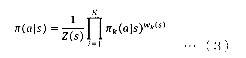
全体の方策π(a|s)は、所定時刻における行動a及びその時の観測状態sを用いて表現された、k番目の副方策πk(a|s)と、各副方策に対する混合重みwk(s)(≧0)と、を用いて、下記の式(3)により表される。
ここで、分配関数Z(s)は、π(a|s)の全定義域における積分が1になるように規定される。
ここで、分配関数Z(s)は、π(a|s)の全定義域における積分が1になるように規定される。
主方策は、車両ごとに個別に作成され、学習される。
副方策は、複数の車両走行間で共有され、学習される。
副方策としては、車両の走行において共通の制御要素又は車種ごとの制御要素を例示することができる。
副方策は、複数の車両走行間で共有され、学習される。
副方策としては、車両の走行において共通の制御要素又は車種ごとの制御要素を例示することができる。
図5は、本実施形態における副方策の事前学習を示すフローチャートである。
図5に示す事前学習は、副方策を得るためのものであるため、シミュレータにより行えばよい。
まず、強化学習部203は、複数(K個)の副方策と、使用車両数の主方策と、を初期化する(S1)。
次に、車両操作制御部213は、学習済みモデル記憶部204に記憶されたモデル情報を主方策及び複数の副方策として読み込む(S2)。
なお、初期化直後のモデル情報は、ランダムに構築されればよい。
次に、シャシーダイナモメータ13上の車両12を交互に入れ替えて複数の車両による試験及び学習を行う(S3)。
S3において、副方策は複数の車両間で共通して用いられ、走行させる車両ごとに対応した主方策が呼び出される。
S3の試験は、学習走行用に用意した指令車速パターンの走行完了を1エピソードとし、エピソードごとに車両の入れ替えを行うが、本発明はこれに限定されるものではなく、車両の入れ替えは所定のタイミングで行えばよい。
なお、S3の試験は副方策を得るためのものであるため、S3の試験において用いられる車両12は、シミュレータで複数用意すればよく、最終的に制御獲得を目指す実際の車両でなくてよい。
図5に示す事前学習は、副方策を得るためのものであるため、シミュレータにより行えばよい。
まず、強化学習部203は、複数(K個)の副方策と、使用車両数の主方策と、を初期化する(S1)。
次に、車両操作制御部213は、学習済みモデル記憶部204に記憶されたモデル情報を主方策及び複数の副方策として読み込む(S2)。
なお、初期化直後のモデル情報は、ランダムに構築されればよい。
次に、シャシーダイナモメータ13上の車両12を交互に入れ替えて複数の車両による試験及び学習を行う(S3)。
S3において、副方策は複数の車両間で共通して用いられ、走行させる車両ごとに対応した主方策が呼び出される。
S3の試験は、学習走行用に用意した指令車速パターンの走行完了を1エピソードとし、エピソードごとに車両の入れ替えを行うが、本発明はこれに限定されるものではなく、車両の入れ替えは所定のタイミングで行えばよい。
なお、S3の試験は副方策を得るためのものであるため、S3の試験において用いられる車両12は、シミュレータで複数用意すればよく、最終的に制御獲得を目指す実際の車両でなくてよい。
図6は、図5に示すS3の処理を示すフローチャートである。
まず、車両操作制御部213は、指令車速及び駆動状態を用いてペダル操作指令を作成する(S31)。
駆動状態取得部211は、該ペダル操作指令に基づく走行データを取得し(S32)、取得した走行データを指令車速生成部22からの指令車速と合わせて、学習データ記憶部201及び車両操作制御部213に送る(S33)。
学習データ記憶部201は、指令車速及び走行データを記憶する(S34)。
この試験は、上述のように、エピソード終了まで行う。
次に、強化学習部203は、車両に対応した主方策300と、共通の副方策301-1,301-2,…,301-Kと、を学習させる(S35)。
この学習は、すべての車両の試験完了まで行う。
本実施形態においては、強化学習部203は上述のMCP法により学習を行う。
報酬設計は、指令車速と検出車速の誤差が小さいほど大きな報酬が得られる設計とする。
図5に示すように、学習して得られたモデル情報により、走行と学習とを繰り返す試験が行われ、複数の車両に共通の汎化的な副方策と、各車両に対応した主方策と、が獲得される。
まず、車両操作制御部213は、指令車速及び駆動状態を用いてペダル操作指令を作成する(S31)。
駆動状態取得部211は、該ペダル操作指令に基づく走行データを取得し(S32)、取得した走行データを指令車速生成部22からの指令車速と合わせて、学習データ記憶部201及び車両操作制御部213に送る(S33)。
学習データ記憶部201は、指令車速及び走行データを記憶する(S34)。
この試験は、上述のように、エピソード終了まで行う。
次に、強化学習部203は、車両に対応した主方策300と、共通の副方策301-1,301-2,…,301-Kと、を学習させる(S35)。
この学習は、すべての車両の試験完了まで行う。
本実施形態においては、強化学習部203は上述のMCP法により学習を行う。
報酬設計は、指令車速と検出車速の誤差が小さいほど大きな報酬が得られる設計とする。
図5に示すように、学習して得られたモデル情報により、走行と学習とを繰り返す試験が行われ、複数の車両に共通の汎化的な副方策と、各車両に対応した主方策と、が獲得される。
なお、同様の副方策しか獲得されないという状況に陥ると、新たな車両への副方策の適応が困難である。
そのため、事前学習は、多様な副方策が獲得されるように行われる。
獲得された副方策が多様でない場合、すなわち副方策の分布の広がりが小さい場合には、使用車両のバリエーションを拡大する。
そのため、事前学習は、多様な副方策が獲得されるように行われる。
獲得された副方策が多様でない場合、すなわち副方策の分布の広がりが小さい場合には、使用車両のバリエーションを拡大する。
図7は、本実施形態における対象車両の主方策の学習を示すフローチャートである。
図7に示す主方策の学習は、図5に示す事前学習後に、実際の車両を用いて行われる。
図7に示す主方策の学習では、事前学習において獲得された副方策の組み合わせを学習すればよいので、実際の車両を用いた学習、すなわち実試験時の学習を従来よりも短くすることができる。
また、このように主方策の学習を行うことで、単純に事前学習で獲得された副方策を組み合わせるよりも実際の車両に対する適応性を高めることができる。
まず、強化学習部203は、試験に用いる使用車両の主方策を初期化する(S11)。
次に、車両操作制御部213は、学習済みモデル記憶部204に記憶されたモデル情報を初期化された主方策及び複数の事前学習済みの副方策として読み込む(S12)。
なお、初期化直後のモデル情報の主方策は、ランダムに構築されればよい。
次に、シャシーダイナモメータ13上の対象車両である車両12について試験及び学習を行う(S13)。
図7に示す主方策の学習は、図5に示す事前学習後に、実際の車両を用いて行われる。
図7に示す主方策の学習では、事前学習において獲得された副方策の組み合わせを学習すればよいので、実際の車両を用いた学習、すなわち実試験時の学習を従来よりも短くすることができる。
また、このように主方策の学習を行うことで、単純に事前学習で獲得された副方策を組み合わせるよりも実際の車両に対する適応性を高めることができる。
まず、強化学習部203は、試験に用いる使用車両の主方策を初期化する(S11)。
次に、車両操作制御部213は、学習済みモデル記憶部204に記憶されたモデル情報を初期化された主方策及び複数の事前学習済みの副方策として読み込む(S12)。
なお、初期化直後のモデル情報の主方策は、ランダムに構築されればよい。
次に、シャシーダイナモメータ13上の対象車両である車両12について試験及び学習を行う(S13)。
図8は、図7に示すS13の処理を示すフローチャートである。
まず、車両操作制御部213は、指令車速及び駆動状態を用いてペダル操作指令を作成する(S131)。
駆動状態取得部211は、該ペダル操作指令に基づく走行データを取得し(S132)、取得した走行データを指令車速生成部22からの指令車速と合わせて、学習データ記憶部201及び車両操作制御部213に送る(S133)。
学習データ記憶部201は、指令車速及び走行データを記憶する(S134)。
この試験は、エピソード終了まで行うが、これに限定されるものではない。
次に、強化学習部203は、車両に対応した主方策300を学習させる(S135)。
この学習は、対象車両の試験完了まで行う。
図7に示すように、学習した主方策を含むモデル情報により、走行と学習とを繰り返す試験が行われ、対象車両に対応した主方策が獲得され、対象車両を制御可能となる。
まず、車両操作制御部213は、指令車速及び駆動状態を用いてペダル操作指令を作成する(S131)。
駆動状態取得部211は、該ペダル操作指令に基づく走行データを取得し(S132)、取得した走行データを指令車速生成部22からの指令車速と合わせて、学習データ記憶部201及び車両操作制御部213に送る(S133)。
学習データ記憶部201は、指令車速及び走行データを記憶する(S134)。
この試験は、エピソード終了まで行うが、これに限定されるものではない。
次に、強化学習部203は、車両に対応した主方策300を学習させる(S135)。
この学習は、対象車両の試験完了まで行う。
図7に示すように、学習した主方策を含むモデル情報により、走行と学習とを繰り返す試験が行われ、対象車両に対応した主方策が獲得され、対象車両を制御可能となる。
なお、本実施形態において、強化学習部203及び車両操作制御部213は、制御装置2の演算部23によって実現される。
すなわち、本実施形態に係る自動操縦ロボットの制御装置2は、強化学習アルゴリズムに基づいた学習により車両の操作を出力する演算部23を備える。
該車両の操作は、複数の車両間で共通の複数の副方策と、MCP法によって得られる、前記複数の副方策が混合されて対象車両に特化された主方策と、により構成される階層構造の方策により行われる。
すなわち、本実施形態に係る自動操縦ロボットの制御装置2は、強化学習アルゴリズムに基づいた学習により車両の操作を出力する演算部23を備える。
該車両の操作は、複数の車両間で共通の複数の副方策と、MCP法によって得られる、前記複数の副方策が混合されて対象車両に特化された主方策と、により構成される階層構造の方策により行われる。
以上説明したように、事前学習により得られた複数の車両間に共通の副方策と、複数の副方策を組み合わせて対象車両に特化させた主方策と、により構成される、階層的な方策構造を用いることで、方策の表現能力が向上し、制御性能が向上する。
更には、複数の車両間に共通の副方策は事前学習により得られ、実際の車両に対する実試験では主方策の学習を行えばよいので、実試験時の学習時間を短くすることができる。
更には、複数の車両間に共通の副方策は事前学習により得られ、実際の車両に対する実試験では主方策の学習を行えばよいので、実試験時の学習時間を短くすることができる。
(実施形態2)
実施形態1ではMCP(Multiplicative Compositional Policies)法によって主方策を得る形態を説明したが、本発明はこれに限定されるものではない。
主方策を得るために、MLSH(Meta Learning Shared Hierarchies)法が用いられてもよい。
実施形態1ではMCP(Multiplicative Compositional Policies)法によって主方策を得る形態を説明したが、本発明はこれに限定されるものではない。
主方策を得るために、MLSH(Meta Learning Shared Hierarchies)法が用いられてもよい。
なお、本実施形態は、実施形態1におけるMCP法をMLSH法に置き換えた点以外は実施形態1と同じであるため、構成等の説明は省略する。
すなわち、本実施形態に係る自動操縦ロボットの制御装置2は、強化学習アルゴリズムに基づいた学習により車両の操作を出力する演算部を備える。
該車両の操作は、複数の車両間で共通の複数の副方策と、MLSH法によって得られる、前記複数の副方策が混合されて対象車両に特化された主方策と、により構成される階層構造の方策により行われる自動操縦ロボットの制御装置である。
すなわち、本実施形態に係る自動操縦ロボットの制御装置2は、強化学習アルゴリズムに基づいた学習により車両の操作を出力する演算部を備える。
該車両の操作は、複数の車両間で共通の複数の副方策と、MLSH法によって得られる、前記複数の副方策が混合されて対象車両に特化された主方策と、により構成される階層構造の方策により行われる自動操縦ロボットの制御装置である。
MLSH法においては、主方策である上位方策(Master Policy)では使用する下位方策が選択され、副方策である下位方策(Sub Policy)では状態における行動である制御方策が選択され、行動が時間に関して分解され、各時刻で使用する下位方策が1つ選択される。
実施形態1におけるMCP法においては、時々刻々の観測状態に応じて副方策の重み付けを決定していたのに対し、本実施形態におけるMLSH法においては、いずれか1つの副方策が選択される。
また、実施形態1におけるMCP法においては、ペダル操作等の行動の基本要素が副方策として表現されやすいのに対し、本実施形態におけるMLSH法においては、制御対象タスクに固有の要素が副方策として表現されやすくなる。
本実施形態によれば、例えば、タスクの特性が時間的に変化するような場合に、指令車速に沿って高精度に追従させる制御を獲得することができる。
また、実施形態1におけるMCP法においては、ペダル操作等の行動の基本要素が副方策として表現されやすいのに対し、本実施形態におけるMLSH法においては、制御対象タスクに固有の要素が副方策として表現されやすくなる。
本実施形態によれば、例えば、タスクの特性が時間的に変化するような場合に、指令車速に沿って高精度に追従させる制御を獲得することができる。
また、MLSH法を用いる場合にも、副方策が互いに異なる振る舞いに特化すると、状態に対して対応する行動バリエーションが多くなり、全体性能を向上させることができる。
車両速度の追従制御では、同一のタスクのみで学習を行うため、副方策の多様性が広がりにくいが、MLSH法を用いる場合にも、副方策に抽象状態を観測させることで、副方策の多様化が可能である。
車両速度の追従制御では、同一のタスクのみで学習を行うため、副方策の多様性が広がりにくいが、MLSH法を用いる場合にも、副方策に抽象状態を観測させることで、副方策の多様化が可能である。
なお、本発明は、上述の実施形態に限定されるものではなく、上述の構成に対して、構成要素の付加、削除又は転換を行った様々な変形例も含むものとする。
1 試験装置
11 ドライブロボット
110a,110b アクチュエータ
12 車両
121 駆動輪
122 運転席
123a,123b 車両操作ペダル
13 シャシーダイナモメータ
14 車両状態計測部
2 制御装置
20 学習部
201 学習データ記憶部
202 データ成型部
203 強化学習部
204 学習済みモデル記憶部
21 ドライブロボット制御部
211 駆動状態取得部
212 データ成型部
213 車両操作制御部
22 指令車速生成部
23 演算部
300,400 主方策
301-1,301-2,…,301-K,401-1,401-2,…,401-K 副方策
11 ドライブロボット
110a,110b アクチュエータ
12 車両
121 駆動輪
122 運転席
123a,123b 車両操作ペダル
13 シャシーダイナモメータ
14 車両状態計測部
2 制御装置
20 学習部
201 学習データ記憶部
202 データ成型部
203 強化学習部
204 学習済みモデル記憶部
21 ドライブロボット制御部
211 駆動状態取得部
212 データ成型部
213 車両操作制御部
22 指令車速生成部
23 演算部
300,400 主方策
301-1,301-2,…,301-K,401-1,401-2,…,401-K 副方策
Claims (2)
- 車両に搭載されて該車両を走行させる自動操縦ロボットを該車両が規定された指令車速に従って走行するように制御する、該自動操縦ロボットの制御装置であって、
強化学習アルゴリズムに基づいた学習により車両の操作を出力する演算部を備え、
該車両の操作は、複数の車両間で共通の複数の副方策と、
MCP法又はMLSH法によって得られる、前記複数の副方策が混合されて対象車両に特化された主方策と、
により構成される階層構造の方策により行われる自動操縦ロボットの制御装置。 - 車両に搭載されて該車両を走行させる自動操縦ロボットを該車両が規定された指令車速に従って走行するように制御する、該自動操縦ロボットの制御方法であって、
複数の車両について走行と学習とを繰り返す試験を行うことで、複数の車両に共通の汎化的な副方策を獲得すること、
MCP法又はMLSH法によって得られる、前記複数の副方策が混合されて対象車両に特化された主方策を獲得することを含む自動操縦ロボットの制御方法。
Applications Claiming Priority (2)
| Application Number | Priority Date | Filing Date | Title |
|---|---|---|---|
| JP2020213407A JP7564704B2 (ja) | 2020-12-23 | 2020-12-23 | 自動操縦ロボットの制御装置及び制御方法 |
| JP2020-213407 | 2020-12-23 |
Publications (1)
| Publication Number | Publication Date |
|---|---|
| WO2022138352A1 true WO2022138352A1 (ja) | 2022-06-30 |
Family
ID=82159139
Family Applications (1)
| Application Number | Title | Priority Date | Filing Date |
|---|---|---|---|
| PCT/JP2021/046168 Ceased WO2022138352A1 (ja) | 2020-12-23 | 2021-12-15 | 自動操縦ロボットの制御装置及び制御方法 |
Country Status (2)
| Country | Link |
|---|---|
| JP (1) | JP7564704B2 (ja) |
| WO (1) | WO2022138352A1 (ja) |
Cited By (1)
| Publication number | Priority date | Publication date | Assignee | Title |
|---|---|---|---|---|
| CN120255487A (zh) * | 2025-06-05 | 2025-07-04 | 深蓝汽车科技有限公司 | 用于车辆转毂实验的车速控制方法、装置、电子设备及车辆 |
Citations (5)
| Publication number | Priority date | Publication date | Assignee | Title |
|---|---|---|---|---|
| CN107862346A (zh) * | 2017-12-01 | 2018-03-30 | 驭势科技(北京)有限公司 | 一种进行驾驶策略模型训练的方法与设备 |
| US20200033869A1 (en) * | 2018-07-27 | 2020-01-30 | GM Global Technology Operations LLC | Systems, methods and controllers that implement autonomous driver agents and a policy server for serving policies to autonomous driver agents for controlling an autonomous vehicle |
| EP3620880A1 (en) * | 2018-09-04 | 2020-03-11 | Autonomous Intelligent Driving GmbH | A method and a device for deriving a driving strategy for a self-driving vehicle and an electronic control unit for performing the driving strategy and a self-driving vehicle comprising the electronic control unit |
| CN111142522A (zh) * | 2019-12-25 | 2020-05-12 | 北京航空航天大学杭州创新研究院 | 一种分层强化学习的智能体控制方法 |
| JP2020148593A (ja) * | 2019-03-13 | 2020-09-17 | 株式会社明電舎 | 自動操縦ロボットを制御する操作推論学習モデルの学習システム及び学習方法 |
-
2020
- 2020-12-23 JP JP2020213407A patent/JP7564704B2/ja active Active
-
2021
- 2021-12-15 WO PCT/JP2021/046168 patent/WO2022138352A1/ja not_active Ceased
Patent Citations (5)
| Publication number | Priority date | Publication date | Assignee | Title |
|---|---|---|---|---|
| CN107862346A (zh) * | 2017-12-01 | 2018-03-30 | 驭势科技(北京)有限公司 | 一种进行驾驶策略模型训练的方法与设备 |
| US20200033869A1 (en) * | 2018-07-27 | 2020-01-30 | GM Global Technology Operations LLC | Systems, methods and controllers that implement autonomous driver agents and a policy server for serving policies to autonomous driver agents for controlling an autonomous vehicle |
| EP3620880A1 (en) * | 2018-09-04 | 2020-03-11 | Autonomous Intelligent Driving GmbH | A method and a device for deriving a driving strategy for a self-driving vehicle and an electronic control unit for performing the driving strategy and a self-driving vehicle comprising the electronic control unit |
| JP2020148593A (ja) * | 2019-03-13 | 2020-09-17 | 株式会社明電舎 | 自動操縦ロボットを制御する操作推論学習モデルの学習システム及び学習方法 |
| CN111142522A (zh) * | 2019-12-25 | 2020-05-12 | 北京航空航天大学杭州创新研究院 | 一种分层强化学习的智能体控制方法 |
Cited By (1)
| Publication number | Priority date | Publication date | Assignee | Title |
|---|---|---|---|---|
| CN120255487A (zh) * | 2025-06-05 | 2025-07-04 | 深蓝汽车科技有限公司 | 用于车辆转毂实验的车速控制方法、装置、电子设备及车辆 |
Also Published As
| Publication number | Publication date |
|---|---|
| JP7564704B2 (ja) | 2024-10-09 |
| JP2022099571A (ja) | 2022-07-05 |
Similar Documents
| Publication | Publication Date | Title |
|---|---|---|
| JP4583028B2 (ja) | 変化する傾斜を有する道路上で駆動されている車両の質量を推定する方法および道路の傾斜を推定する方法 | |
| WO2020183864A1 (ja) | 自動操縦ロボットを制御する操作推論学習モデルの学習システム及び学習方法 | |
| Pasquier et al. | Fuzzylot: a novel self-organising fuzzy-neural rule-based pilot system for automated vehicles | |
| KR20150133662A (ko) | 차량 시험 시스템 | |
| CN113614743A (zh) | 用于操控机器人的方法和设备 | |
| CN105934576B (zh) | 用于内燃机的基于模型的气缸充气检测 | |
| WO2009024268A2 (de) | Modellierungsverfahren und steuergerät für einen verbrennungsmotor | |
| Zou et al. | Inverse reinforcement learning via neural network in driver behavior modeling | |
| CN110281949A (zh) | 一种自动驾驶统一分层决策方法 | |
| EP1623284A1 (de) | Verfahren zur optimierung von fahrzeugen und von motoren zum antrieb solcher fahrzeuge | |
| WO2022138352A1 (ja) | 自動操縦ロボットの制御装置及び制御方法 | |
| DE102020210744A1 (de) | System zum modellieren einer antiblockiersystemsteuerung eines fahrzeugs | |
| JP2009129366A (ja) | 車両の感性推定システム | |
| JP2025540687A (ja) | 報酬モデルを使用したマルチモーダルインタラクティブエージェントのトレーニング | |
| Albeaik et al. | Deep truck: A deep neural network model for longitudinal dynamics of heavy duty trucks | |
| JP2022174734A (ja) | 建設現場用のオフロード車両のための方策を学習するための装置および方法 | |
| JP2021103356A (ja) | 制御装置、制御装置の制御方法、プログラム、情報処理サーバ、情報処理方法、並びに制御システム | |
| JP2024526706A (ja) | ドライブコントロールする方法 | |
| CN113657604A (zh) | 用于运行检查台的设备和方法 | |
| WO2021149435A1 (ja) | 自動操縦ロボットの制御装置及び制御方法 | |
| JP2021143882A (ja) | 自動操縦ロボットを制御する操作推論学習モデルの学習システム及び学習方法 | |
| DE102023125034A1 (de) | Bestimmung eines Verschleißes einer Fahrzeugkomponente mit einem KI-Modul | |
| CN118219925A (zh) | 使用振动数据和soh反馈来控制电池组振动 | |
| Sailer et al. | Adaptive model-based velocity control by a robotic driver for vehicles on roller dynamometers | |
| CN118883099B (zh) | 一种基于神经网络的制动abs功能标定方法及装置 |
Legal Events
| Date | Code | Title | Description |
|---|---|---|---|
| 121 | Ep: the epo has been informed by wipo that ep was designated in this application |
Ref document number: 21910501 Country of ref document: EP Kind code of ref document: A1 |
|
| NENP | Non-entry into the national phase |
Ref country code: DE |
|
| 122 | Ep: pct application non-entry in european phase |
Ref document number: 21910501 Country of ref document: EP Kind code of ref document: A1 |