WO2022138286A1 - 固定床反応器 - Google Patents
固定床反応器 Download PDFInfo
- Publication number
- WO2022138286A1 WO2022138286A1 PCT/JP2021/045840 JP2021045840W WO2022138286A1 WO 2022138286 A1 WO2022138286 A1 WO 2022138286A1 JP 2021045840 W JP2021045840 W JP 2021045840W WO 2022138286 A1 WO2022138286 A1 WO 2022138286A1
- Authority
- WO
- WIPO (PCT)
- Prior art keywords
- bed reactor
- inlet baffle
- shielding
- fixed bed
- pipe
- Prior art date
- Legal status (The legal status is an assumption and is not a legal conclusion. Google has not performed a legal analysis and makes no representation as to the accuracy of the status listed.)
- Ceased
Links
Images




Classifications
-
- B—PERFORMING OPERATIONS; TRANSPORTING
- B01—PHYSICAL OR CHEMICAL PROCESSES OR APPARATUS IN GENERAL
- B01J—CHEMICAL OR PHYSICAL PROCESSES, e.g. CATALYSIS OR COLLOID CHEMISTRY; THEIR RELEVANT APPARATUS
- B01J19/00—Chemical, physical or physico-chemical processes in general; Their relevant apparatus
- B01J19/24—Stationary reactors without moving elements inside
-
- B—PERFORMING OPERATIONS; TRANSPORTING
- B01—PHYSICAL OR CHEMICAL PROCESSES OR APPARATUS IN GENERAL
- B01J—CHEMICAL OR PHYSICAL PROCESSES, e.g. CATALYSIS OR COLLOID CHEMISTRY; THEIR RELEVANT APPARATUS
- B01J8/00—Chemical or physical processes in general, conducted in the presence of fluids and solid particles; Apparatus for such processes
- B01J8/02—Chemical or physical processes in general, conducted in the presence of fluids and solid particles; Apparatus for such processes with stationary particles, e.g. in fixed beds
Definitions
- This disclosure relates to a fixed bed reactor.
- a fixed bed reactor is used as a device for reacting raw materials in equipment such as a petrochemical plant (for example, Patent Document 1).
- a reaction layer is arranged at the lower part and a raw material introduction layer is arranged at the upper part, and the raw material is supplied to the inside from a pipe connected above.
- a disc-shaped inlet baffle is arranged directly below the inlet of the pipe to the fixed-bed reactor in the raw material introduction layer, and the raw material is supplied from above to the inside.
- the raw material may not be evenly supplied to the entire main surface of the inlet baffle. In this case, since the raw materials are not evenly diffused inside the fixed bed reactor, the supply to the reaction layer may be uneven and the production amount may decrease.
- the present disclosure aims to provide a fixed bed reactor capable of evenly diffusing the raw materials supplied internally.
- This disclosure has the following configuration.
- the fixed-bed reactor includes a pipe that introduces a gas-liquid two-phase flow from the upper part of the fixed-bed reactor to the inside and the pipe inside the fixed-bed reactor.
- the inlet baffle is provided with an inlet baffle arranged opposite to the inlet to the fixed floor reactor, the inlet baffle is a flat plate arranged horizontally, and the inlet of the pipe is arranged directly above the center position of the inlet baffle.
- the shield portion having a shielding surface facing the center position side and suppressing the gas-liquid two-phase flow from scattering to the outer diameter side of the inlet baffle on the main surface of the inlet baffle is the above-mentioned pipe.
- the outer diameter of the introduction port is arranged radially outside from the position projected on the inlet baffle, and is erected upward.
- a curved tube having a horizontal portion in which the pipe extends in the horizontal direction and a vertical portion that bends at a substantially right angle from the horizontal portion and is connected to the fixed floor reactor.
- the shielding portion is arranged on the side opposite to the extending direction of the horizontal portion.
- the shielding surface is arranged so as to face the axial direction of the horizontal portion of the pipe.
- the inlet baffle is a polygonal flat plate or disk.
- the fixed bed reactor according to any one of [1] to [3].
- the shape of the shielding surface is a flat surface or a curved surface.
- the fixed bed reactor according to any one of [1] to [4].
- the shielding portion is a plate-shaped member.
- the fixed bed reactor according to any one of [1] to [5].
- the shape of the shielding portion is a flat plate shape, an arc shape, or a cylindrical shape.
- the shielding surface When the normal direction of the shielding surface is horizontal, the shielding surface is inclined toward the center of the inlet baffle when the inclination angle of the shielding surface with respect to the main surface of the inlet baffle is 90 degrees.
- the inclination angle of the shielding surface shifts to the 0 degree side, and when the shielding surface inclines to the outer edge side of the inlet baffle, the inclination angle of the shielding surface shifts to the 180 degree side.
- the tilt angle of the shielding surface is in the range of 40 degrees to 115 degrees.
- the fixed bed reactor according to any one of [1] to [7].
- the inclination angle of the shielding surface is in the range of 85 degrees to 110 degrees.
- the inclination angle of the shielding surface is 90 degrees.
- the normal direction of the shielding surface is the horizontal direction.
- the extending direction of the shielding surface is the direction perpendicular to the inlet baffle.
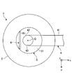
- Top view showing the structure in the raw material introduction layer of the fixed bed reactor which concerns on embodiment.
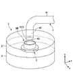
- Enlarged perspective view of the vicinity of the raw material introduction layer of the fixed bed reactor Schematic diagram showing the range of the shielding plate in the vertical direction Schematic diagram showing the reference numerals corresponding to each dimension in the fixed bed reactor.
- the figure which shows the 1st modification of a shielding plate The figure which shows the 2nd deformation example of a shielding plate
- the figure which shows the relationship between the inclination angle of a shielding plate and the uneven distribution improvement rate of a droplet flux The figure which shows the droplet flux distribution of Example 2 and Comparative Example 2.
- the x-direction, y-direction, and z-direction are perpendicular to each other.
- the x-direction and the y-direction are horizontal directions, and the z-direction is a vertical direction.
- the x direction is the axial direction of the horizontal portion 41 of the pipe 4. Further, when the normal direction of the shielding surface 61 is the horizontal direction and the inclination angle of the shielding surface 61 with respect to the main surface 51 of the inlet baffle 5 is 90 degrees, the inclination angle of the shielding surface 61 is 90 degrees in the x direction. This is the normal direction of the shielding surface 61 at the time of.
- the y direction is the longitudinal direction of the shielding plate 6 when the shielding plate 6 is on a flat plate.
- the z positive direction side may be expressed as the upper side and the z negative direction side may be expressed as the lower side.
- FIG. 1 is a vertical sectional view showing a schematic configuration of a fixed bed reactor 1 according to an embodiment.
- FIG. 2 is a plan view showing the configuration of the fixed bed reactor 1 according to the embodiment in the raw material introduction layer 2.
- FIG. 3 is an enlarged perspective view of the vicinity of the raw material introduction layer 2 of the fixed bed reactor 1.
- FIG. 1 is an example of a case where the fixed bed reactor is a multi-tube fixed bed reactor.
- the raw material introduction layer 2 is arranged at the upper part and the reaction layer 3 is arranged at the lower part.
- the raw material introduction layer 2 and the reaction layer 3 are separated by a tube plate surface 7.
- a pipe for introducing a gas-liquid two-phase flow M (a mixed fluid composed of a gas as a continuous phase and a droplet as a dispersed phase) as a raw material inside the raw material introduction layer 2. 4 is connected.
- the fixed bed reactor 1 discharges the reaction product from below by reacting the raw material supplied to the raw material introduction layer 2 through the pipe 4 with the catalyst in the reaction layer 3.
- the reaction layer 3 is provided on the outside of the reaction tube 8 and the reaction tube 8 filled with a solid catalyst or the like, and heats and removes heat from the reaction tube 8. It consists of a heat medium distribution unit for the purpose.
- the fixed-bed reactor is not limited to the multi-tube reactor, and may be a reactor in which all the reaction layers are filled with a solid filler or a solid catalyst.
- the pipe 4 is preferably a curved pipe having a horizontal portion 41 extending in the horizontal direction and a vertical portion 42 bent at a substantially right angle from the horizontal portion 41 and connected to the fixed floor reactor 1.
- Examples of the pipe 4 having such a structure include a single elbow type pipe in which two linear pipes are connected by a joint pipe (elbow) that bends at 90 degrees.
- a type of pipe other than the single elbow, such as a double elbow type, may be applied to the pipe 4.
- the horizontal portion 41 is arranged so that its axis is in the x direction
- the vertical portion 42 is arranged so that its axis is in the z direction.
- the cross-sectional shape of the pipe 4 is also substantially circular
- the fixed floor reactor 1 is substantially cylindrical with the z direction as the central axis
- the vertical portion 42 of the pipe 4 is the center position of the substantially circular end face above the cylindrical portion 42. It is connected to the center of the fixed bed reactor 1 so that the axis overlaps with C.
- An inlet baffle 5 is provided inside the raw material introduction layer 2.
- the inlet baffle 5 is a flat plate arranged horizontally, and one main surface 51 is arranged vertically upward (z positive direction).
- the inlet baffle 5 has a disk shape in FIG. 1 and is arranged to face the introduction port 43 of the pipe 4 to the fixed floor reactor 1. More specifically, the introduction port 43 of the pipe 4 is arranged directly above the center position C of the inlet baffle 5.
- the center position C of the circular main surface 51 of the inlet baffle 5 is the same as the center position C of the fixed bed reactor 1 described above. That is, in a plan view, the introduction port 43 of the pipe 4, the inlet baffle 5, and the outer shape of the fixed bed reactor 1 are arranged concentrically as shown in FIG.
- the inlet baffle 5 has an inlet 43 of the pipe 4 and the reaction layer 3 in order to prevent the reaction layer 3 from being damaged by the raw material M introduced from the pipe 4 directly colliding with the reaction layer 3 below. It is arranged so as to intervene between them.
- the inlet baffle 5 is generally provided perpendicular to the flow of the gas-liquid two-phase flow M for the purpose of buffering. As a result, as shown in FIG. 1, the raw material M introduced from the pipe 4 once collides with the inlet baffle 5, is reflected, is decelerated, and then is supplied to the reaction layer 3.
- the shielding plate 6 (shielding portion) is erected upward on the main surface 51 of the inlet baffle 5.
- the shielding plate 6 has a shielding surface 61 facing the center position C side of the inlet baffle 5.
- the shielding surface 61 is a gas-liquid two-phase flow that is reflected at the center position C of the inlet baffle 5 and moves outward in the radial direction (x negative direction in the example of FIG. 1). It receives a part of M and reflects it in the opposite direction (x positive direction side in the example of FIG. 1).
- the shielding surface 61 partially suppresses the gas-liquid two-phase flow M from scattering toward the outer diameter side of the inlet baffle 5.
- the fixed bed reactor 1 of the present embodiment can evenly diffuse the raw material M supplied to the inside by providing the shielding plate 6 so as to obstruct the flow of the gas-liquid two-phase flow M.
- the inlet baffle 5 is preferably a polygonal flat plate or a disk, and more preferably a disk.
- a polygonal flat plate it is preferably a regular polygon having a large number of vertices whose contour is close to a circle, and the number of vertices is preferably more than 10,000.
- the shielding plate 6 is preferably a flat plate-shaped member, and the flat surface of one of the main surfaces functions as the shielding surface 61.
- the shapes of the shielding plate 6 and the shielding surface 61 are rectangular with the y direction as the longitudinal direction.
- the shielding plate 6 is arranged so that the normal direction of the shielding surface 61 is the horizontal direction, and when the shielding plate 6 is a flat plate, the extending direction of the shielding surface 61 is the vertical direction from the inlet baffle 5. Is preferable.
- the shielding surface 61 of the shielding plate 6 is arranged so as to face the axial direction (x direction) of the horizontal portion 41 of the pipe 4.
- the shielding plate 6 is preferably arranged radially outside the position where the outer diameter of the introduction port 43 of the pipe 4 is projected onto the inlet baffle 5.
- the fixed bed reactor 1 of the present embodiment can diffuse the raw material M supplied to the inside more evenly by adopting the configuration of such a shielding plate 6.
- the effect of equalizing the diffusion of the gas-liquid two-phase flow M by the shielding plate 6 is particularly remarkable when the pipe 4 is a single elbow type shown in FIG. 1 or the like.
- the gas-liquid two-phase flow M flows into the reactor after the traveling direction is bent by 90 degrees just before the reactor inlet due to the elbow shape, and the inertia due to the bending of the elbow shape It is considered to be strongly affected. Therefore, in the conventional reactor, the gas-liquid two-phase flow in the raw material introduction layer 2 is on the traveling direction side of the horizontal portion 41 of the pipe 4, that is, on the side opposite to the horizontal portion 41 with the central position C in the plan view.
- the supply is strongly unevenly distributed in the region on the x negative direction side (see FIGS. 8 (A) and 10 (A)).
- the shielding plate 6 can suppress the flow of the gas-liquid two-phase flow M in the direction of the region, and as a result, it is considered that the diffusion equalization of the gas-liquid two-phase flow M can be promoted. Be done. Then, the gas-liquid two-phase flow M is evenly diffused in the fixed bed reactor 1 in the outer peripheral direction of the inlet baffle 5, so that the production amount of the reaction product can be improved.
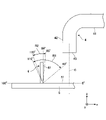
- FIG. 4 is a schematic view showing a range of the shielding plate 6 in the vertical direction.
- the inclination angle of the shielding surface 61 with respect to the main surface 51 of the inlet baffle 5 is 90 degrees.
- the shielding surface 61 is inclined toward the center C side of the inlet baffle 5, the inclination angle of the shielding surface 61 shifts to the 0 degree side, and conversely, when the shielding surface 61 is inclined toward the outer edge side of the inlet baffle 5.
- the inclination angle of the shielding surface 61 shifts to the 180 degree side.
- the extending direction of the shielding surface 61 is perpendicular to the inlet baffle 5.
- the inclination angle of the shielding surface 61 is preferably in the range of 40 degrees to 115 degrees.
- the inclination angle of the shielding surface 61 is more preferably in the range of 85 degrees to 110 degrees. Further, it is more preferable that the inclination angle of the shielding surface 61 is 90 degrees.
- the raw material M supplied to the inside of the fixed bed reactor 1 can be diffused more evenly.
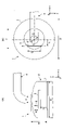
- FIG. 5 is a schematic diagram showing reference numerals corresponding to each dimension in the fixed bed reactor 1.
- 5A is a vertical cross-sectional view similar to that of FIG. 1
- FIG. 5B is a plan view similar to that of FIG.
- the pipe diameter is d and the reactor diameter is D.
- the vertical coordinates of the inlet baffle 5 with respect to the pipe plate surface 7 are h
- the height from the pipe plate surface 7 to the joint between the pipe 4 and the reactor 1 is H
- the shield is shielded.
- E be the height of the plate 6 in the z direction.
- the distance from the center position C of the inlet baffle 5 to the shielding plate 6 is L
- the diameter of the inlet baffle 5 is F
- the width of the shielding plate 6 in the longitudinal direction (y direction) is G. do.
- the diameter F of the inlet baffle 5 is preferably 0.3D or more and 0.4D or less.
- the installation position h / H (0 ⁇ h / H ⁇ 1) of the inlet baffle 5 is preferably 0.2 or more and 0.8 or less.
- the distance L from the center position C of the shielding plate 6 is preferably larger than the pipe diameter d.
- the width G of the shielding plate 6 is preferably larger than the pipe diameter d. It is preferable that the height E of the shielding plate 6 is 0.2H or more and the dimension does not come into contact with the upper wall surface of the reactor 1.
- the gas-liquid two-phase flow M of the raw material has a fluid velocity of 8 to 15 m / s passing through the pipe 4. Further, it is desirable that the droplet concentration of the gas-liquid two-phase flow M is less than 10% of the volume fraction.
- the raw material M supplied to the inside of the fixed bed reactor 1 can be diffused more evenly.
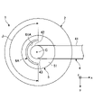
- FIG. 6 is a diagram showing a first modification of the shielding plate 6A.
- the shielding plate 6A may have an arc shape.
- the arc shape of the shielding plate 6A is formed around the center position C of the inlet baffle 5.
- the shielding surface 61A has a curved surface along the arc shape.
- the arc-shaped shielding plate 6A of the first modification is a shielding plate when the diameter F of the inlet baffle 5 is less than ⁇ 2d, that is, when the shielding plate is flat and the plate width G corresponding to the pipe diameter d cannot be obtained. It is effective to satisfy the condition that the width H in the longitudinal direction of 6A is larger than the pipe diameter d.
- the width J of the shielding plate 6A is preferably ⁇ d / 2 or more and less than ⁇ d / ⁇ 2. When the arc-shaped shielding plate 6A is erected with an inclination, it is preferable that the shielding surface 61A is inclined uniformly.
- FIG. 7 is a diagram showing a second modification of the shielding plate 6B.
- the shielding plate 6B may be cylindrical.
- the cylindrical shape of the shielding plate 6B is formed around the center position C of the inlet baffle 5.
- the shielding surface 61B is a cylindrical inner peripheral surface and has a curved surface shape.
- the inner diameter of the cylindrical shape of the shielding plate 6B is preferably larger than the pipe diameter d.
- the type of the fixed bed reactor applied to this embodiment may be a single tube type or a multi-tube type.
- a single-tube reactor there are no restrictions on the outer diameter or length of the reactor, and it is arbitrarily determined from the viewpoint of ensuring the mass velocity and diffusing the substance into the reactor.
- a multi-tube reactor is usually used when the reaction is accompanied by heat generation or endothermic.
- the reaction tube is usually a cylindrical straight tube having the same outer diameter, wall thickness and length, and the inner diameter of the reaction tube is 4 times or more the diameter of the catalyst to be filled. It is preferable to determine so as to be, and it is industrially selected from the range of about 15 to 50 mm, but it is not particularly limited.
- the reaction may generally be carried out in a fixed bed reactor, for example, ethylene oxide production by ethylene oxidation, achlorine and acrylic acid production by propylene oxidation, metachlorine and methacrylic acid production by isobutylene oxidation.
- Example 1 The ratio of the pipe diameter d, the diameter of the circular bottom plate (diameter F of the inlet baffle 5) to the reactor diameter D was set to 1: 5: 20.
- the position h / H of the inlet baffle 5 was set to 0.4.
- the shape of the shielding plate 6 was a flat plate, the height E was 0.2H, and the width G was 0.2D.
- the flow velocity of the gas-liquid two-phase flow M was 10 m / s, and the droplet concentration was 5% by mass. Under this condition, the droplet flux distribution in the plan view of the raw material introduction layer 2 of the fixed bed reactor 1 was measured.
- the droplet flux is the product of the droplet concentration and the vertical gas flow velocity (droplet concentration x gas flow velocity).
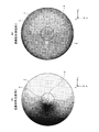
- FIG. 8 is a diagram showing a droplet flux distribution in a plane including the main surface 51 of the inlet baffle 5 of Example 1 and Comparative Example 1.
- FIG. 8A is the result of Comparative Example 1
- FIG. 8B is the result of Example 1.
- the distribution is shown so that the smaller the droplet flux, the closer to white, and the larger the droplet flux, the closer to black.
- the droplet flux is biased to the left side in the figure (the region opposite to the horizontal portion 41 of the pipe 4), resulting in the droplet flux in the entire plane.
- the standard deviation of is 3.7 ⁇ 10-5 , and it can be seen that the droplet flux is uneven in the entire plane.
- FIG. 8B it can be seen that in the state where the shielding plate 6 is present, the dark-colored portion is reduced as compared with (A), and the overall unevenness is suppressed.
- the standard deviation of the droplet flux over the entire plane is 1.3 ⁇ 10-5 , which can be reduced to about 1/3 as compared with (A) without the shielding plate 6.
- Example 1 and Comparative Example 1 shown in FIG. 8 by providing the shielding plate 6 on the inlet baffle 5, the droplet flux distribution in the plan view of the raw material introduction layer 2 of the fixed bed reactor 1 is obtained. It was shown that the gas-liquid two-phase flow M of the raw material supplied to the inside can be uniformly diffused.
- FIG. 9 is a diagram showing the relationship between the inclination angle of the shielding plate 6 and the uneven distribution improvement rate of the droplet flux.
- the horizontal axis of FIG. 9 indicates the inclination angle (°) of the shielding plate 6.
- the vertical axis of FIG. 9 shows the improvement rate with respect to the base.
- the improvement rate is 50% or more, and it can be seen that the effect of sufficiently improving the uneven distribution of the droplet flux is obtained.
- the improvement rate is 60% or more, and it can be seen that the effect of improving the uneven distribution of the droplet flux is further exhibited.
- the improvement rate is maximized, and it can be seen that the effect of improving the uneven distribution of the droplet flux is most exerted.
- the inclination angle of the shielding plate 6 is preferably in the range of 40 degrees to 115 degrees, and more preferably in the range of 85 degrees to 110 degrees. , 90 degrees was shown to be even more preferred.
- Example 2 Implemented except that the ratio of the pipe diameter d, the diameter of the circular bottom plate (diameter F of the inlet baffle 5), and the reactor diameter D is 3: 4:10, and the shape of the shielding plate 6A is arcuate.
- the droplet flow flux distribution in the plan view of the raw material introduction layer 2 of the fixed bed reactor 1 was measured in the same manner as in Example 1.
- the width J of the shielding plate 6A was set to 0.42D.
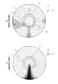
- FIG. 10 is a diagram showing a droplet flux distribution on a plane including the main surface 51 of the inlet baffle 5 of Example 2 and Comparative Example 2.
- FIG. 10A is the result of Comparative Example 2
- FIG. 10B is the result of Example 2.
- the display mode of the flow velocity distribution in FIG. 10 is the same as that in FIG.
- the droplet flux is biased toward the left side of the figure (the region opposite to the horizontal portion 41 of the pipe 4), resulting in the droplet flux of the entire plane.
- the standard deviation of is 9.7 ⁇ 10 -3 , and it can be seen that the droplet flux is uneven in the entire plane.
- FIG. 10B it can be seen that in the state where the shielding plate 6A is present, the dark-colored portion is reduced as compared with (A), and the overall unevenness is suppressed.
- the standard deviation of the droplet flux over the entire plane is 2.0 ⁇ 10 -3 , which is reduced to about 1/5 of that of (A) without the shielding plate 6.
- Example 2 and Comparative Example 2 shown in FIG. 10 As described above, from the results of Example 2 and Comparative Example 2 shown in FIG. 10, even if the inlet baffle 5 is provided with the arc-shaped shielding plate 6A, the liquid in the plan view of the raw material introduction layer 2 of the fixed bed reactor 1 can be obtained. It was shown that the droplet flux distribution can be made uniform and the gas-liquid two-phase flow M of the raw material supplied to the inside can be evenly diffused.
- Example 3 Comparative Example 3 The conditions were the same as in Example 2 except that the shielding plate 6A was arranged inside the pipe diameter d. The width J of the shielding plate 6A was set to 0.27D.
- FIG. 11 is a diagram showing a droplet flux distribution in a plane including the main surface 51 of the inlet baffle 5 of Comparative Example 3.
- the display mode of the flow velocity distribution in FIG. 11 is the same as that in FIGS. 8 and 10.
- Comparative Example 3 when the shielding plate 6A is inside the pipe 4, the standard deviation of the droplet flux is 5.0 ⁇ 10 -3 , which is about 1 / compared with Comparative Example 2. Although it can be reduced to 2, it shows the same deviation of the droplet flux distribution as in the case without the shielding plate 6A of Comparative Example 2. Therefore, as shown in FIGS. 2, 6 and 7, the shielding plates 6, 6A and 6B are arranged radially outside the position where the outer diameter of the introduction port 43 of the pipe 4 is projected onto the inlet baffle 5. It was shown that it is preferable to be done.
- the configuration in which the shielding plate 6 of the plate-shaped member is provided on the inlet baffle 5 is exemplified, but the configuration has a shielding surface 61 for suppressing the gas-liquid two-phase flow M from scattering to the outer diameter side of the inlet baffle 5. Anything may be sufficient, and other than the plate-shaped member may be used.
- a block-shaped shielding portion such as a rectangular parallelepiped or a cube may be installed on the main surface 51 of the inlet baffle 5 instead of the shielding plate 6, and the block-shaped shielding portion may have a shielding surface 61.
Landscapes
- Chemical & Material Sciences (AREA)
- Organic Chemistry (AREA)
- Chemical Kinetics & Catalysis (AREA)
- Devices And Processes Conducted In The Presence Of Fluids And Solid Particles (AREA)
Abstract
Description
前記遮蔽部は前記水平部の延在方向と反対側に配置される、
[1]に記載の固定床反応器。
[2]に記載の固定床反応器。
[1]~[3]のいずれか1項に記載の固定床反応器。
[1]~[4]のいずれか1項に記載の固定床反応器。
[1]~[5]のいずれか1項に記載の固定床反応器。
[6]に記載の固定床反応器。
前記遮蔽面の傾斜角度は40度~115度の範囲である、
[1]~[7]のいずれか1項に記載の固定床反応器。
[8]に記載の固定床反応器。
[8]または[9]に記載の固定床反応器。
前記遮蔽面の延在方向が前記インレットバッフルから垂直方向である、
[1]~[7]のいずれか1項に記載の固定床反応器。
・使用ソフト:ANSYS社製の汎用数値流体解析ソフトANSYS(登録商標) Fluent(登録商標)
・連続相(ガス=気相)支配方程式:N-S方程式、連続の式
・乱流モデル:k-εモデル
・気液二相流解析:Euler-Lagrange型(ガス流体をEuler型、液滴をLagrange型で解析)
・分散相流れ:液相
・粒子追跡法(DPM(Discrete Phase Model)):One Way Coupling
・解析対称:配管および反応器
配管径dと、円形形状の底板の径(インレットバッフル5の径F)と、反応器径Dとの比率を1:5:20とした。インレットバッフル5の位置h/Hは0.4とした。遮蔽板6の形状は平板状とし、高さEは0.2H、幅Gは0.2Dとした。気液二相流Mの流速は10m/s、液滴濃度は5質量%とした。この条件下で、固定床反応器1の原料導入層2の平面視における液滴流束分布を計測した。液滴流束は、液滴濃度と鉛直方向ガス流速との積(液滴濃度×ガス流速)である。
遮蔽板6を設けない点以外は実施例1と同様の条件とした。
さらに遮蔽板6の傾斜角度を変更する点以外は実施例1と同様の条件とした。遮蔽板6の傾斜角度は、図4を参照して説明した条件で、15度、30度、45度、75度、90度、110度、120度とした。各傾斜角度において、実施例1と同様のシミュレーションを行って液滴流束分布を計測し、液滴流束の標準偏差を算出した。遮蔽板6無しの場合の比較例1の標準偏差を基準(ベース)として、各傾斜角度の標準偏差の減少率を、比較例に対する液滴流束の偏在の改善率(対ベース改善率)として算出した。
配管径dと、円形形状の底板の径(インレットバッフル5の径F)と、反応器径Dとの比率を3:4:10とし、遮蔽板6Aの形状を円弧状とした点以外は実施例1と同様の条件とし、実施例1と同様に固定床反応器1の原料導入層2の平面視における液滴流束分布を計測した。遮蔽板6Aの幅Jは0.42Dとした。
遮蔽板6Aを設けない点以外は実施例2と同様の条件とした。
遮蔽板6Aを配管径dの内側に配置した点以外は実施例2と同様の条件とした。遮蔽板6Aの幅Jは0.27Dとした。
4 配管
41 水平部
42 垂直部
5 インレットバッフル
6、6A、6B 遮蔽板(遮蔽部)
7 管板面
8 反応管
61、61A、61B 遮蔽面
Claims (11)
- 固定床反応器であって、
当該固定床反応器の上部から内部に気液二相流を導入する配管と、
当該固定床反応器の内部で前記配管の当該固定床反応器への導入口と対向配置されるインレットバッフルと、を備え、
前記インレットバッフルが水平配置の平板であり、
前記配管の前記導入口が前記インレットバッフルの中心位置の直上に配置され、
前記インレットバッフルの主面上において、前記中心位置側を向き前記気液二相流が前記インレットバッフルの外径側に飛散するのを抑制する遮蔽面を有する遮蔽部が、前記配管の前記導入口の外径を前記インレットバッフル上に投影した位置より径方向外側に配置され、上方に向けて立設される、
固定床反応器。 - 前記配管が水平方向に延在する水平部と、水平部から略直角に屈曲し、当該固定床反応器に接続される垂直部とを有する曲がり菅であり、
前記遮蔽部は前記水平部の延在方向と反対側に配置される、
請求項1に記載の固定床反応器。 - 前記遮蔽面は、前記配管の前記水平部の軸線方向と正対して配置される、
請求項2に記載の固定床反応器。 - 前記インレットバッフルが、多角形の平板または円板である、
請求項1~3のいずれか1項に記載の固定床反応器。 - 前記遮蔽面の形状が、平面状または曲面状である、
請求項1~4のいずれか1項に記載の固定床反応器。 - 前記遮蔽部が板状部材である、
請求項1~5のいずれか1項に記載の固定床反応器。 - 前記遮蔽部の形状が、平板状、円弧状、または円筒状である、
請求項6に記載の固定床反応器。 - 前記遮蔽面の法線方向が水平方向であるとき前記インレットバッフルの前記主面に対する前記遮蔽面の傾斜角度を90度とするときに、前記遮蔽面が前記インレットバッフルの中心側に傾斜するときに前記遮蔽面の傾斜角度が0度側に遷移し、前記遮蔽面が前記インレットバッフルの外縁側に傾斜するときに前記遮蔽面の傾斜角度が180度側に遷移する、と規定した場合、
前記遮蔽面の傾斜角度は40度~115度の範囲である、
請求項1~7のいずれか1項に記載の固定床反応器。 - 前記遮蔽面の傾斜角度は85度~110度の範囲である、
請求項8に記載の固定床反応器。 - 前記遮蔽面の傾斜角度は90度である、
請求項8または9に記載の固定床反応器。 - 前記遮蔽面の法線方向が水平方向であり、
前記遮蔽面の延在方向が前記インレットバッフルから垂直方向である、
請求項1~7のいずれか1項に記載の固定床反応器。
Priority Applications (2)
| Application Number | Priority Date | Filing Date | Title |
|---|---|---|---|
| JP2022572172A JP7642970B2 (ja) | 2020-12-21 | 2021-12-13 | 固定床反応器 |
| CN202180086162.XA CN116648304A (zh) | 2020-12-21 | 2021-12-13 | 固定床反应器 |
Applications Claiming Priority (2)
| Application Number | Priority Date | Filing Date | Title |
|---|---|---|---|
| JP2020-211664 | 2020-12-21 | ||
| JP2020211664 | 2020-12-21 |
Publications (1)
| Publication Number | Publication Date |
|---|---|
| WO2022138286A1 true WO2022138286A1 (ja) | 2022-06-30 |
Family
ID=82157925
Family Applications (1)
| Application Number | Title | Priority Date | Filing Date |
|---|---|---|---|
| PCT/JP2021/045840 Ceased WO2022138286A1 (ja) | 2020-12-21 | 2021-12-13 | 固定床反応器 |
Country Status (4)
| Country | Link |
|---|---|
| JP (1) | JP7642970B2 (ja) |
| CN (1) | CN116648304A (ja) |
| TW (1) | TWI800160B (ja) |
| WO (1) | WO2022138286A1 (ja) |
Cited By (1)
| Publication number | Priority date | Publication date | Assignee | Title |
|---|---|---|---|---|
| CN116272686A (zh) * | 2023-01-03 | 2023-06-23 | 东方电气集团东方锅炉股份有限公司 | 一种混合流列管式固定床反应器 |
Citations (4)
| Publication number | Priority date | Publication date | Assignee | Title |
|---|---|---|---|---|
| JPH0463126A (ja) * | 1990-07-02 | 1992-02-28 | Uop Inc | 流体分配装置 |
| US5160513A (en) * | 1991-11-13 | 1992-11-03 | Uop | Inlet stream debris collection method and apparatus |
| JP2004531596A (ja) * | 2001-03-01 | 2004-10-14 | シエル・インターナシヨネイル・リサーチ・マーチヤツピイ・ベー・ウイ | 自己支持型の反応器内部構造物 |
| JP2017514687A (ja) * | 2014-03-14 | 2017-06-08 | モーテン・ミューラー・リミテッド・アンパルトセルスカブ | 下降二相流を有するベッセル用のスケール収集および事前分配トレイ |
Family Cites Families (2)
| Publication number | Priority date | Publication date | Assignee | Title |
|---|---|---|---|---|
| US9861947B2 (en) * | 2012-02-28 | 2018-01-09 | Phillips 66 Company | Reactor inlet vapor velocity equalizer and distributor |
| RU2672742C1 (ru) * | 2016-11-25 | 2018-11-19 | Чайна Петролиум энд Кемикал Корпорейшн | Диск, ослабляющий ударное воздействие и создающий равномерный поток, и реактор |
-
2021
- 2021-12-13 JP JP2022572172A patent/JP7642970B2/ja active Active
- 2021-12-13 WO PCT/JP2021/045840 patent/WO2022138286A1/ja not_active Ceased
- 2021-12-13 CN CN202180086162.XA patent/CN116648304A/zh active Pending
- 2021-12-15 TW TW110146979A patent/TWI800160B/zh active
Patent Citations (4)
| Publication number | Priority date | Publication date | Assignee | Title |
|---|---|---|---|---|
| JPH0463126A (ja) * | 1990-07-02 | 1992-02-28 | Uop Inc | 流体分配装置 |
| US5160513A (en) * | 1991-11-13 | 1992-11-03 | Uop | Inlet stream debris collection method and apparatus |
| JP2004531596A (ja) * | 2001-03-01 | 2004-10-14 | シエル・インターナシヨネイル・リサーチ・マーチヤツピイ・ベー・ウイ | 自己支持型の反応器内部構造物 |
| JP2017514687A (ja) * | 2014-03-14 | 2017-06-08 | モーテン・ミューラー・リミテッド・アンパルトセルスカブ | 下降二相流を有するベッセル用のスケール収集および事前分配トレイ |
Cited By (1)
| Publication number | Priority date | Publication date | Assignee | Title |
|---|---|---|---|---|
| CN116272686A (zh) * | 2023-01-03 | 2023-06-23 | 东方电气集团东方锅炉股份有限公司 | 一种混合流列管式固定床反应器 |
Also Published As
| Publication number | Publication date |
|---|---|
| JP7642970B2 (ja) | 2025-03-11 |
| CN116648304A (zh) | 2023-08-25 |
| JPWO2022138286A1 (ja) | 2022-06-30 |
| TW202235150A (zh) | 2022-09-16 |
| TWI800160B (zh) | 2023-04-21 |
Similar Documents
| Publication | Publication Date | Title |
|---|---|---|
| JP2023092209A (ja) | 固定床反応器 | |
| US7807729B2 (en) | Heat-expanded microspheres, production process thereof, heat-expandable microspheres and application thereof | |
| US20120121907A1 (en) | Thermally expanded microspheres and a process for producing the same | |
| EP0684871B1 (en) | Fluidized-bed reactor | |
| CN102824890B (zh) | 一种具有交替流动结构的催化精馏填料 | |
| JP7642970B2 (ja) | 固定床反応器 | |
| TWI429481B (zh) | 混合裝置 | |
| EP2723781B1 (en) | Method and apparatus for discharging a polymer from a gas-phase reactor | |
| JP2009534178A (ja) | 高分散流体を接触物質床の全域にわたって分配するための流体分配トレイ及び方法 | |
| JPH11262702A (ja) | アトマイジング・ノズル及びその使用方法 | |
| EP2174706A1 (en) | Apparatus and process for gas phase fluidised bed polymerisation | |
| JP5691151B2 (ja) | 熱交換型反応器を用いた反応方法 | |
| JP2009512546A5 (ja) | ||
| CN100534602C (zh) | 气固流化床内构件 | |
| CN202621143U (zh) | 一种上行式气液分布器 | |
| CN108854862A (zh) | 一种颗粒物床层支撑格栅和径向流反应器 | |
| US9713800B2 (en) | Multi-tubular reactor and multi-tubular reactor design and fabrication method | |
| KR100866757B1 (ko) | 반응기 및 열교환기 환상도관을 위한 열매체 분산기구 | |
| CN109046186A (zh) | 一种催化剂流化单元及流化床催化反应器 | |
| US20230026757A1 (en) | Gas Distribution Plate, Fluidizing Device and Reaction Method | |
| CN209205257U (zh) | 填料单元及流化床气固接触设备 | |
| CN223969513U (zh) | 一种导流链式液体分布器 | |
| US8388840B2 (en) | System for stiffening the plates of a large-diameter multi-stage column | |
| Krishnamurty et al. | Gas—Solids Fluidization in Baffled Beds | |
| JP2003117381A (ja) | 流動層反応器のガス拡散筒 |
Legal Events
| Date | Code | Title | Description |
|---|---|---|---|
| 121 | Ep: the epo has been informed by wipo that ep was designated in this application |
Ref document number: 21910435 Country of ref document: EP Kind code of ref document: A1 |
|
| ENP | Entry into the national phase |
Ref document number: 2022572172 Country of ref document: JP Kind code of ref document: A |
|
| WWE | Wipo information: entry into national phase |
Ref document number: 202180086162.X Country of ref document: CN |
|
| NENP | Non-entry into the national phase |
Ref country code: DE |
|
| 122 | Ep: pct application non-entry in european phase |
Ref document number: 21910435 Country of ref document: EP Kind code of ref document: A1 |