WO2022137665A1 - 電子制御装置 - Google Patents
電子制御装置 Download PDFInfo
- Publication number
- WO2022137665A1 WO2022137665A1 PCT/JP2021/033207 JP2021033207W WO2022137665A1 WO 2022137665 A1 WO2022137665 A1 WO 2022137665A1 JP 2021033207 W JP2021033207 W JP 2021033207W WO 2022137665 A1 WO2022137665 A1 WO 2022137665A1
- Authority
- WO
- WIPO (PCT)
- Prior art keywords
- software
- control software
- buffer
- transmission information
- driver
- Prior art date
- Legal status (The legal status is an assumption and is not a legal conclusion. Google has not performed a legal analysis and makes no representation as to the accuracy of the status listed.)
- Ceased
Links
Images






Classifications
-
- G—PHYSICS
- G06—COMPUTING OR CALCULATING; COUNTING
- G06F—ELECTRIC DIGITAL DATA PROCESSING
- G06F13/00—Interconnection of, or transfer of information or other signals between, memories, input/output devices or central processing units
- G06F13/10—Program control for peripheral devices
- G06F13/102—Program control for peripheral devices where the program performs an interfacing function, e.g. device driver
-
- G—PHYSICS
- G06—COMPUTING OR CALCULATING; COUNTING
- G06F—ELECTRIC DIGITAL DATA PROCESSING
- G06F11/00—Error detection; Error correction; Monitoring
- G06F11/07—Responding to the occurrence of a fault, e.g. fault tolerance
- G06F11/14—Error detection or correction of the data by redundancy in operations
- G06F11/1402—Saving, restoring, recovering or retrying
- G06F11/1415—Saving, restoring, recovering or retrying at system level
- G06F11/1417—Boot up procedures
-
- B—PERFORMING OPERATIONS; TRANSPORTING
- B60—VEHICLES IN GENERAL
- B60R—VEHICLES, VEHICLE FITTINGS, OR VEHICLE PARTS, NOT OTHERWISE PROVIDED FOR
- B60R16/00—Electric or fluid circuits specially adapted for vehicles and not otherwise provided for; Arrangement of elements of electric or fluid circuits specially adapted for vehicles and not otherwise provided for
- B60R16/02—Electric or fluid circuits specially adapted for vehicles and not otherwise provided for; Arrangement of elements of electric or fluid circuits specially adapted for vehicles and not otherwise provided for electric constitutive elements
- B60R16/023—Electric or fluid circuits specially adapted for vehicles and not otherwise provided for; Arrangement of elements of electric or fluid circuits specially adapted for vehicles and not otherwise provided for electric constitutive elements for transmission of signals between vehicle parts or subsystems
- B60R16/0231—Circuits relating to the driving or the functioning of the vehicle
-
- G—PHYSICS
- G06—COMPUTING OR CALCULATING; COUNTING
- G06F—ELECTRIC DIGITAL DATA PROCESSING
- G06F11/00—Error detection; Error correction; Monitoring
- G06F11/07—Responding to the occurrence of a fault, e.g. fault tolerance
- G06F11/0703—Error or fault processing not based on redundancy, i.e. by taking additional measures to deal with the error or fault not making use of redundancy in operation, in hardware, or in data representation
- G06F11/0766—Error or fault reporting or storing
- G06F11/0778—Dumping, i.e. gathering error/state information after a fault for later diagnosis
-
- G—PHYSICS
- G06—COMPUTING OR CALCULATING; COUNTING
- G06F—ELECTRIC DIGITAL DATA PROCESSING
- G06F2213/00—Indexing scheme relating to interconnection of, or transfer of information or other signals between, memories, input/output devices or central processing units
- G06F2213/40—Bus coupling
Definitions
- This disclosure relates to an electronic control device.
- a microcomputer (hereinafter referred to as a "microcomputer") is equipped with a CPU (Central Processing Unit), a memory, a peripheral, and the like. Peripherals include one or more peripheral circuits to provide various functions to a microcomputer.
- Patent Document 1 discloses a device for restarting a peripheral when the peripheral becomes abnormal.
- microcomputers equipped with multiple control software have been known. From the viewpoint of size and cost, there is a limit to the number of peripheral circuits mounted on the microcomputer. Therefore, a plurality of control software may share one peripheral circuit.
- the present disclosure provides a technique capable of the second control software to continue processing by using the peripheral circuit even in a situation where an abnormality occurs in the first control software.
- the electronic control device includes a memory for storing the first control software and the second control software, a CPU for executing the first control software and the second control software, the first control software, and the first control software. It includes a peripheral circuit used by the second control software.
- the memory further includes a first buffer and a second buffer.
- the CPU has a first storage process for storing the first peripheral transmission information, which is transmission information from the first control software to the peripheral circuit, in the first buffer, and the second control software.
- a second storage process for storing the second peripheral transmission information, which is transmission information to the peripheral circuit, in the second buffer, and outputting the first peripheral transmission information from the first buffer to the peripheral circuit.
- the first output process and the second output process for outputting the second peripheral transmission information from the second buffer to the peripheral circuit are configured to be executed.
- the CPU interrupts at least one of the first storage process and the first output process in a specific situation in which an abnormality related to the first control software occurs, and the second storage process and the second output process are interrupted. It is configured to continue output processing.
- the electronic control device performs the processing (second storage processing and second output processing) related to the second control software even in the specific situation where the abnormality related to the first control software occurs. You can continue. Further features relating to the present invention will be apparent from the description herein and the accompanying drawings. In addition, problems, configurations, and effects other than those described above will be clarified by the following description of the embodiments.
- the following plurality of examples relate to an electronic control device equipped with a plurality of control software, respectively.
- an embodiment of an electronic control device equipped with two control softwares first control software and second control software
- the configuration of the electronic control device is not limited to this, and the electronic control device may further include other control software (for example, a third control software and a fourth control software).
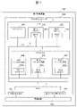
- FIG. 1 is a diagram showing a hardware configuration of an electronic control device.
- the electronic control device 1000 includes a microcomputer 900 and a power supply circuit 901.
- the microcomputer 900 includes a CPU 1, a peripheral 2, a memory 3, and a bus 4.
- the CPU 1, the peripheral 2, and the memory 3 are connected to each other via the bus 4. Therefore, the CPU 1 can access the peripheral 2 and the memory 3 via the bus 4.
- Memory 3 stores a plurality of software.
- the CPU 1 executes the software stored in the memory 3.
- the microcomputer 900 further includes a self-reset signal output terminal 911 and an external reset terminal 912.
- the self-reset signal output terminal 911 and the external reset terminal 912 are each connected to the power supply circuit 901.
- the microcomputer 900 outputs a reset request signal to the power supply circuit 901 via the self-reset signal output terminal 911.
- the power supply circuit 901 inputs an external reset signal to the external reset terminal 912 in response to the reset request signal.
- the microcomputer 900 receives the external reset signal, the microcomputer 900 is restarted.
- the CPU 1 includes a plurality of cores. Specifically, the CPU 1 includes a main CPU core 100, a first CPU core 101, and a second CPU core 102.
- the first CPU core 101 includes a first MPU (Memory Protection Unit) 101a.
- the first MPU 101a includes setting information regarding an area of the memory 3 accessible to the first CPU core 101 (hereinafter, referred to as “first accessible area”).
- the first MPU 101a allows the first CPU core 101 to access the first accessible area.
- the first MPU 101a prohibits the first CPU core 101 from accessing an area other than the first accessible area.
- the second CPU core 102 includes the second MPU 102a.
- the second MPU 102a includes setting information regarding an area of the memory 3 accessible to the second CPU core 102 (hereinafter, referred to as a “second accessible area”).
- the second MPU 102a allows the second CPU core 102 to access the second accessible area.
- the second MPU 102a prohibits the second CPU core 102 from accessing an area other than the second accessible area.
- the main CPU core 100 executes processing related to the main OS (Operating System) 301 (see FIG. 2).
- the first CPU core 101 executes processing related to the first control software 310 (see FIG. 2).
- the second CPU core 102 executes processing related to the second control software 320 (see FIG. 2).
- the CPU 1 is not limited to the above configuration.
- the CPU 1 may include four or more CPU cores.
- the CPU 1 may include a plurality of first CPU cores 101.
- each of the plurality of first CPU cores 101 includes the first MPU 101a.
- the CPU 1 may include a plurality of second CPU cores 102.
- each of the plurality of second CPU cores 102 includes the second MPU 102a.
- the peripheral 2 includes a plurality of peripheral circuits.
- the peripheral circuit refers to a circuit other than the CPU 1 and the memory 3 among the components mounted on the microcomputer 900.
- Examples of peripheral circuits include a CAN (Controller Area Network) controller, an analog-to-digital converter (A / D converter), a direct memory access controller, a GPIO (General Purpose Input / Output), and the like.
- the peripheral 2 includes a shared peripheral circuit 200, a first peripheral circuit 201, and a second peripheral circuit 202.
- the shared peripheral circuit 200 includes a CAN controller 200a.
- the first peripheral circuit 201 includes a first GPIO pin 201a for analog.
- the second peripheral circuit 202 includes a second GPIO pin 202a for digital use.
- the shared peripheral circuit 200 is a peripheral circuit used by both the first control software 310 (that is, the first CPU core 101) and the second control software 320 (that is, the second CPU core 102).
- the shared peripheral circuit 200 is also accessed from the main CPU core 100.
- the first peripheral circuit 201 is a peripheral circuit used only by the first control software 310 (that is, the first CPU core 101).
- the second peripheral circuit 202 is a peripheral circuit used only by the second control software 320 (that is, the second CPU core 102).
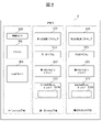
- FIG. 2 is a diagram showing software stored in the memory 3.
- the memory 3 stores a plurality of software.
- the memory 3 stores the control task 300, the main OS 301, and the CAN driver 302.
- the main CPU core 100 executes these softwares 300 to 302.
- the main OS 301 initializes the CAN driver 302.
- the CAN driver 302 is software corresponding to the shared peripheral circuit 200, and is software that outputs an operation command to the CAN controller 200a.
- the main OS 301 starts the first sub OS 311 and the second sub OS 321. That is, the main OS 301 transmits a start command of the first sub OS 311 to the first CPU core 101, and sends a start command of the second sub OS 321 to the second CPU core 102.
- the main OS 301 activates the control task 300 in a cycle of 1 ms.
- the execution cycle of the control task 300 is 1 ms, but the present invention is not limited to this.
- the detailed processing contents of the control task 300 will be described later.
- the memory 3 further stores the first control software 310, the first sub OS 311 and the first GPIO pin driver 312, and the first virtual CAN driver 313.
- the first CPU core 101 executes these softwares 310 to 313.
- the first sub OS311 initializes the first GPIO pin driver 312 according to the boot command from the main OS301.
- the first GPIO pin driver 312 is software that outputs an operation instruction to the first GPIO pin 201a.
- the first sub OS311 starts the first control software 310 according to the start command from the main OS 301.
- the first control software 310 includes one or more tasks.
- the task of the first control software 310 is executed by the first sub-OS 311 at a predetermined timing.
- the first control software 310 transmits the first peripheral transmission information at a predetermined timing.
- the first peripheral transmission information is information transmitted to the CAN controller 200a.
- the first sub OS311 initializes the first virtual CAN driver 313 according to the start command from the main OS301.
- the first virtual CAN driver 313 is software that intervenes between the first control software 310 and the CAN driver 302, and is software that processes the first peripheral transmission information.
- the first virtual CAN driver 313 includes a first buffer 313a.
- the first virtual CAN driver 313 stores the first peripheral transmission information in the first buffer 313a.
- the memory 3 further stores the second control software 320, the second sub OS 321, the second GPIO pin driver 322, and the second virtual CAN driver 323.
- the second CPU core 102 executes these softwares 320 to 323.
- the software executed by the second CPU core 102 will be described.
- software 320 to 323 will be described as the subject. However, since the subject that executes the software 320 to 323 is the second CPU core 102, the subject may be replaced with the second CPU core 102.
- the second sub OS 321 initializes the second GPIO pin driver 322 according to the boot command from the main OS 301.
- the second GPIO pin driver 322 is software that outputs an operation instruction to the second GPIO pin 202a.
- the second sub OS 321 starts the second control software 320 according to the start command from the main OS 301.
- the second control software 320 includes one or more tasks.
- the task of the second control software 320 is executed at a predetermined timing by the second sub OS 321.
- the second control software 320 transmits the second peripheral transmission information at a predetermined timing.
- the second peripheral transmission information is information transmitted to the CAN controller 200a.
- the second sub OS 321 initializes the second virtual CAN driver 323 according to the start command from the main OS 301.
- the second virtual CAN driver 323 is software that intervenes between the second control software 320 and the CAN driver 302, and is software that processes the second peripheral transmission information.
- the second virtual CAN driver 323 includes a second buffer 323a.
- the second virtual CAN driver 323 stores the second peripheral transmission information in the second buffer 323a.
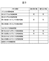
- FIG. 3 is a diagram showing setting information regarding the first accessible area in the first MPU 101a.
- the first CPU core 101 has a read right and a write right for the storage area of the software 310 to 313.
- the first CPU core 101 does not have a read right and a write right for an area other than the storage area of the software 310 to 313. This makes it possible to prevent the first control software 310 (that is, the first CPU core 101) from affecting the main OS 301 and the second control software 320.
- FIG. 4 is a diagram showing setting information regarding the second accessible area in the second MPU 102a.
- the second CPU core 102 has a read right and a write right for the storage area of the software 320 to 323.
- the second CPU core 102 does not have a read right and a write right for an area other than the storage area of the software 320 to 323. This makes it possible to prevent the second control software 320 (that is, the second CPU core 102) from affecting the main OS 301 and the first control software 310.
- the main CPU core 100 can access all the areas of the memory 3.
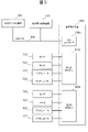
- FIG. 5 is a diagram showing a connection relationship between the electronic control device 1000 and an external device.
- the processing contents of the first control software 310 and the second control software 320 will be described.
- the plurality of sensors 511 and the plurality of actuators 512 are arranged outside the electronic control device 1000.
- the plurality of sensors 511 and the plurality of actuators 512 are each connected to the first GPIO pin 201a.
- the first control software 310 accesses the first GPIO pin 201a and inputs an analog signal to each of the plurality of actuators 512. Further, the first control software 310 receives analog signals from each of the plurality of sensors 511 via the first GPIO pin 201a. The first control software 310 transmits the first peripheral transmission information based on these analog signals.
- the first peripheral transmission information is a CAN message transmitted from the first control software 310 to each of the other electronic control devices 540.
- the first peripheral transmission information is output to the CAN controller 200a via the first buffer 313a, as will be described later.
- the CAN controller 200a receives the first peripheral transmission information.
- the CAN controller 200a converts the first peripheral transmission information into a physical signal, and transmits the physical signal to another electronic control device 540 via the CAN bus 530.
- the plurality of sensors 521 and the plurality of actuators 522 are arranged outside the electronic control device 1000.
- the plurality of sensors 521 and the plurality of actuators 522 are each connected to the second GPIO pin 202a.
- the second control software 320 accesses the second GPIO pin 202a and inputs a digital signal to each of the plurality of actuators 522. Further, the second control software 320 receives digital signals from each of the plurality of sensors 521 via the second GPIO pin 202a. The second control software 320 transmits the second peripheral transmission information based on these digital signals.
- the second peripheral transmission information is a CAN message transmitted from the second control software 320 to each of the other electronic control devices 540.
- the second peripheral transmission information is output to the CAN controller 200a via the second buffer 323a, as will be described later.
- the CAN controller 200a receives the second peripheral transmission information.
- the CAN controller 200a converts the second peripheral transmission information into a physical signal, and transmits the physical signal to another electronic control device 540 via the CAN bus 530.
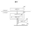
- FIG. 6 is a diagram showing an outline of the operation of the CAN driver 302 and the operation of the CAN controller 200a.
- the CAN driver 302 stores the first peripheral transmission information in a predetermined location in the internal register 200b of the CAN controller 200a.
- the CAN controller 200a stores the first peripheral transmission information in the CAN frame 600 according to a predetermined CAN protocol. Then, the CAN controller 200a converts the CAN frame 600 into a physical signal and transmits it to the CAN bus 530.
- FIG. 7 is a diagram showing an input / output relationship between a plurality of software.
- there are two virtual CAN drivers that is, a first virtual CAN driver 313 and a second virtual CAN driver 323) in front of the CAN driver 302.
- the first control software 310 and the second control software 320 use the first virtual CAN driver 313 and the second virtual CAN driver 323, respectively.
- the control task 300 alternately accesses the first virtual CAN driver 313 and the second virtual CAN driver 323, and alternately outputs the first peripheral transmission information 710 and the second peripheral transmission information 720 to the CAN driver 302. do.
- one CAN driver 302 can be used while separating the processing of the first control software 310 and the processing of the second control software 320.
- the first control software 310 transmits the first peripheral transmission information 710 to the first virtual CAN driver 313.
- the first virtual CAN driver 313 stores the first peripheral transmission information 710 in the first buffer 313a.
- the second control software 320 transmits the second peripheral transmission information 720 to the second virtual CAN driver 323.
- the second virtual CAN driver 323 stores the second peripheral transmission information 720 in the second buffer 323a.
- the control task 300 takes out the first peripheral transmission information 710 from the first buffer 313a and outputs the first peripheral transmission information 710 to the CAN driver 302.
- the control task 300 takes out the second peripheral transmission information 720 from the second buffer 323a and outputs the second peripheral transmission information 720 to the CAN driver 302.
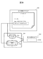
- FIG. 8 is a diagram illustrating a process flow when the first control software 310 transmits the first peripheral transmission information 710.
- the first control software 310 designates the CAN message ID and data as the first peripheral transmission information 710.
- the first control software 310 calls CAN_send_virtio1 (ID, data).
- CAN_send_virtio1 (ID, data) is a command for transmitting the first peripheral transmission information 710 to the first virtual CAN driver 313.
- the first peripheral transmission information 710 includes the CAN message ID 711 and the data 712.
- the first virtual CAN driver 313 receives the first peripheral transmission information 710.
- the first virtual CAN driver 313 stores the first peripheral transmission information 710 in the first buffer 313a.
- the second control software 320 transmits the second peripheral transmission information 720.
- the second control software 320 designates the CAN message ID and data as the second peripheral transmission information 720.
- the second control software 320 calls CAN_send_virtio2 (ID, data).
- CAN_send_virtio2 (ID, data) is a command for transmitting the second peripheral transmission information 720 to the second virtual CAN driver 323.
- the second peripheral transmission information 720 includes the CAN message ID 721 and the data 722.
- the second virtual CAN driver 323 receives the second peripheral transmission information 720.
- the second virtual CAN driver 323 stores the second peripheral transmission information 720 in the second buffer 323a.
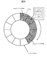
- FIG. 9 is a diagram showing the data structure of the first buffer 313a.
- the first buffer 313a has a ring buffer structure, which is one of the implementations of the First-In-First-Out queue.
- Each element of the first buffer 313a is a structure composed of a set of CAN message ID and data.
- the substance of the ring buffer is the structure array buffer_virtio1 [12].
- the number of elements in the array is set to 12, but the number is not limited to this.
- the first virtual CAN driver 313 calculates the index backward representing the buffer end position as follows (backward ⁇ (backward + 1)% 12 ). Here, "%" is an operator for finding the remainder when (backward + 1) is divided by 12.
- the first virtual CAN driver 313 assigns "0" to the backward.
- the first virtual CAN driver 313 stores the first peripheral transmission information 710 in buffer_virtio1 [backward]. As described above, the first virtual CAN driver 313 stores the first peripheral transmission information 710 at the end of the first buffer 313a.
- a storage process of the first peripheral transmission information 710 is referred to as a “first storage process”.
- FIG. 10 is a diagram showing the data structure of the second buffer 323a.
- the second buffer 323a has a ring buffer structure, which is one of the implementations of the First-In-First-Out queue.
- Each element of the second buffer 323a is a structure composed of a set of CAN message ID and data.
- the substance of the ring buffer is the structure array buffer_virtio2 [12].
- the number of elements in the array is set to 12, but the number is not limited to this.
- the second virtual CAN driver 323 stores the second peripheral transmission information 720 in buffer_virtio2 [backward]. As described above, the second virtual CAN driver 323 stores the second peripheral transmission information 720 at the end of the second buffer 323a.
- a storage process of the second peripheral transmission information 720 is referred to as a “second storage process”.
- FIG. 11 is a state transition diagram held inside the control task 300.
- the control task 300 is a task started by the main OS 301 in a cycle of 1 ms.
- the control task 300 alternately executes the first output process and the second output process.
- control task 300 is in the first state St1. In this case, the control task 300 executes the first output process.
- the control task 300 determines whether or not the second buffer 323a is empty after executing the first output process. If the second buffer 323a is not empty, the control task 300 transitions from the first state St1 to the second state St2. On the other hand, when the second buffer 323a is empty and the first buffer 313a is not empty (that is, when only the second buffer 323a is empty), the control task 300 maintains the first state St1. In this case, the control task 300 repeatedly executes the first output process.
- both the first buffer 313a and the second buffer 323a are empty after the control task 300 executes the first output process, the control task 300 changes from the first state St1 to the third state St3. And transition. In this case, the control task 300 does nothing. After that, when the first buffer 313a is not empty (that is, when the first peripheral transmission information 710 is stored in the first buffer 313a), the control task 300 moves from the third state St3 to the first state St1. Transition. Alternatively, if the second buffer 323a is not empty (that is, the second peripheral transmission information 720 is stored in the second buffer 323a), the control task 300 moves from the third state St3 to the second state St2. Transition.
- control task 300 has transitioned from the first state St1 to the second state St2. In this case, the control task 300 executes the second output process.
- the control task 300 determines whether or not the first buffer 313a is empty after executing the second output process. If the first buffer 313a is not empty, the control task 300 transitions from the second state St2 to the first state St1. On the other hand, when the first buffer 313a is empty and the second buffer 323a is not empty (that is, when only the first buffer 313a is empty), the control task 300 maintains the second state St2. In this case, the control task 300 repeatedly executes the second output process.
- the control task 300 changes from the first state St1 to the third state St3. And transition. In this case, the control task 300 does nothing. After that, when the first buffer 313a is not empty (that is, when the first peripheral transmission information 710 is stored in the first buffer 313a), the control task 300 moves from the third state St3 to the first state St1. Transition. Alternatively, if the second buffer 323a is not empty (that is, the second peripheral transmission information 720 is stored in the second buffer 323a), the control task 300 moves from the third state St3 to the second state St2. Transition.
- an abnormality may occur with respect to the first control software 310.
- a situation is referred to as a "specific situation".
- the specific situation includes, for example, a situation in which an abnormality has occurred in the first control software 310, and a situation in which an abnormality has occurred in the software and hardware related to the first control software 310.
- the specific situation means a situation in which at least one of the following (1) to (3) occurs.
- the first control software 310 executes processing other than normal processing (so-called exception processing).
- the normal processing is the transmission processing of the first peripheral transmission information 710.
- Exception handling includes, for example, access to areas other than the first accessible area (out-of-area access), processing related to deadline mistakes, and the like.
- An abnormality has occurred in the software related to the first control software 310 (for example, the first GPIO pin driver 312).
- An abnormality has occurred in the hardware related to the first control software 310.
- Such hardware includes (a) the CPU 1 and the memory 3, (b) the sensor 511 and the actuator 522 connected to the first GPIO pin 201a, and (c) the destination of the first peripheral transmission information 710.
- a common peripheral circuit 200 and the like can be mentioned.
- the first control software 310 transmits the first interruption command to the first virtual CAN driver 313 in a specific situation.
- the first suspension command includes a command for suspending the first storage process and a command for initializing the first buffer 313a.
- the first virtual CAN driver 313 suspends (prohibits) the first storage process in response to the first suspension command. Further, the first virtual CAN driver 313 initializes the first buffer 313a (that is, emptys the first buffer 313a) in response to the first interruption command.
- the first virtual CAN driver 313 can initialize the first buffer 313a by substituting the index forward indicating the buffer start position into the index backward indicating the buffer end position.
- the first virtual CAN driver 313 interrupts the first storage process and initializes the first buffer 313a in response to the first interruption command. Since the first buffer 313a is empty, the control task 300 maintains the second state St2 (see FIG. 11). In other words, the control task 300 interrupts the first output process. On the other hand, the control task 300 continues the second storage process and the second output process.
- the first control software 310 and the second control software 320 use the first virtual CAN driver 313 and the second virtual CAN driver 323, respectively.
- the control task 300 alternately accesses the first virtual CAN driver 313 and the second virtual CAN driver 323, and alternately outputs the first peripheral transmission information 710 and the second peripheral transmission information 720 to the CAN driver 302. do.
- the processing of the first control software 310 and the processing of the second control software 320 are separated. Therefore, the second control software 320 can continue the second storage process and the second output process even in the specific situation where the abnormality related to the first control software 310 occurs. That is, the second control software 320 can continue to transmit the second peripheral transmission information 720 to the CAN controller 200a.
- the inappropriate first peripheral transmission information 710 may be output to the CAN driver 302. Since the first virtual CAN driver 313 initializes the first buffer 313a, it is possible to prevent the above-mentioned problems from occurring.
- the first CPU core 101 executes the process related to the first control software 310
- the second CPU core 102 executes the process related to the second control software 320. Therefore, the two CPU cores 101 and 102 can continue processing independently of each other. It is possible to prevent the processing executed by one CPU core from affecting the processing executed by the other CPU core.
- the same process is executed even when an abnormality occurs in the second control software 320.
- the second control software 320 transmits a second interruption command to the second virtual CAN driver 323.
- the second suspension command includes a command for suspending the second storage process and a command for initializing the second buffer 323a.
- the second virtual CAN driver 323 suspends (prohibits) the second storage process in response to the second suspend command. Further, the second virtual CAN driver 323 initializes the second buffer 323a.
- the second virtual CAN driver 323 can initialize the second buffer 323a by substituting the index forward indicating the buffer start position into the index backward indicating the buffer end position.
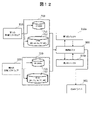
- FIG. 12 is a diagram showing an input / output relationship between a plurality of software in this example.
- the control task 300 is configured to execute all of the first storage process, the second storage process, the first output process, and the second output process.
- the control task 300 receives the first peripheral transmission information 710 from the first control software 310 and executes the first storage process. Further, the control task 300 receives the second peripheral transmission information 720 from the second control software 320 and executes the second storage process.
- the control task 300 executes the first output process and the second output process according to the state transition diagram of FIG.
- the first control software 310 transmits a third interruption command to the control task 300 in a specific situation.
- the third suspension command includes only the command for suspending the first storage process.
- the control task 300 suspends the first storage process in response to the third suspension command.
- the control task 300 continues the first output process until the first buffer 313a becomes empty. When the first buffer 313a becomes empty, the control task 300 interrupts the first output process. On the other hand, the control task 300 continues the second storage process and the second output process.
- the second control software 320 can continue the second storage process and the second output process even in a specific situation.
- the third interruption command includes only the command for interrupting the first output processing.
- the control task 300 interrupts the first output process in response to the third interruption command.
- the control task 300 may continue only the first storage process.
- the control task 300 may continue the first storage process until all the elements of the array of the first buffer 313a are filled. When all the elements of the array of the first buffer 313a are filled, the control task 300 interrupts the first storage process. On the other hand, the control task 300 continues the second storage process and the second output process.
- control task 300 may interrupt both the first storage process and the first output process in a specific situation. Therefore, the first peripheral transmission information 710 in the first buffer 313a is held.
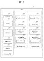
- Example 3 The configuration of the electronic control device 1000 in the third embodiment will be described. Hereinafter, the differences from the first embodiment will be mainly described. As shown in FIG. 13, in this example, the memory 3 further stores the initialization task 304 and the diagnostic task 305. The main CPU core 100 further executes these softwares 304 and 305. The same components as those in the first embodiment are designated by the same reference numerals, and the description thereof will be omitted.
- the main OS 301 initializes the CAN driver 302.
- the main OS 301 activates the control task 300 and the initialization task 304 in a cycle of 1 ms.
- the execution cycle of the control task 300 and the initialization task 304 is 1 ms, but the present invention is not limited to this.
- the main OS 301 activates the diagnostic task 305 at a cycle of 10 ms.
- the execution cycle of the diagnostic task 305 is 10 ms, but is not limited to this.
- FIG. 14 is an example of the diagnostic information table 1400 generated by the diagnostic task 305.
- the diagnosis information table 1400 includes a diagnosis target 1401 and a state 1402 as constituent items.
- the diagnosis target 1401 is hardware or software to be diagnosed.
- the state 1402 is information indicating whether the diagnosis target 1401 is in a normal state or an abnormal state.
- the diagnostic task 305 monitors whether each of the diagnostic targets 1401 in the diagnostic information table 1400 is operating normally at a cycle of 10 ms. Accordingly, the diagnostic task 305 updates the state 1402 of the diagnostic information table 1400.
- the diagnostic task 305 confirms whether the hardware of the electronic control device 1000 is operating normally.
- the hardware here includes a main CPU core 100, a first CPU core 101, a second CPU core 102, a CAN controller 200a, a first GPIO pin 201a and a second GPIO pin 202a.
- the diagnostic task 305 has a first accessible area (area of memory 3 accessible by the first CPU core 101) and a second accessible area (area of memory 3 accessible by the second CPU core 102). Check if there is a memory error in.
- the memory error may be detected by a method such as parity check and CRC (Cyclic Redundancy Check), or may be detected by other methods.
- the diagnostic task 305 confirms whether the first control software 310 is operating normally.
- the diagnostic task 305 may determine that an abnormality has occurred in the first control software 310 when the first control software 310 is executing exception handling. Further, the diagnostic task 305 confirms whether the second control software 320 is operating normally.
- the diagnosis task 305 determines that the diagnosis target 1401 is operating normally, the diagnosis task 305 sets the corresponding state 1402 to "normal". When the diagnosis task 305 determines that an abnormality has occurred in the diagnosis target 1401, the corresponding state 1402 is set to "abnormal”. As a result, the initialization task 304 can confirm whether or not each of the diagnosis targets 1401 is operating normally by referring to the diagnosis information table 1400.
- the diagnostic information table 1400 is not limited to the above example.
- the diagnostic task 305 may confirm whether the first sub OS 311 and the second sub OS 321 are operating normally.
- FIG. 15 is an example of the initialization policy table 1500 held by the initialization task 304.
- the initialization policy table 1500 includes the target 1501 in which the abnormality has occurred and the initialization policy 1502 as configuration items.
- the initialization policy 1502 indicates which initialization process is to be executed.
- the initialization process includes a whole initialization process, a first initialization process, and a second initialization process.
- the initialization task 304 determines whether or not an abnormality has occurred in the diagnosis target 1401 by referring to the diagnosis information table 1400. When an abnormality has occurred in the diagnosis target 1401, the initialization task 304 refers to the initialization policy table 1500 to set the initialization policy 1502 corresponding to the diagnosis target (that is, the target 1501 in which the abnormality has occurred). get. The initialization task 304 executes the initialization process according to the acquired initialization policy 1502.
- the initialization task 304 executes the entire initialization process. Further, when the CAN controller 200a has an abnormality, the initialization task 304 executes the entire initialization process.
- the initialization task 304 executes the first initialization process.
- the initialization task 304 executes the second initialization process.
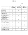
- FIG. 16 is an example of the initialization range table 1600 held by the initialization task 304.
- the initialization range table 1600 shows which hardware and software each initialization process initializes.
- the overall initialization process is a process that initializes all hardware and software.
- the initialization task 304 executes the entire initialization process as follows.
- the initialization task 304 outputs a reset request signal to the power supply circuit 901 via the self-reset signal output terminal 911.
- the power supply circuit 901 inputs an external reset signal to the external reset terminal 912 in response to the reset request signal.
- the microcomputer 900 receives the external reset signal, the microcomputer 900 is restarted. In this way, all the hardware and software on the microcomputer 900 are initialized.
- the first initialization process is a process for initializing the hardware and software related to the first CPU core 101.
- the initialization task 304 executes the first initialization process as follows.
- the initialization task 304 restarts the first CPU core 101.
- the initialization task 304 restarts the first sub OS 311.
- the initialization task 304 sends a predetermined start command to the first sub-OS 311.
- the first sub-OS 311 initializes the first GPIO pin driver 312 according to the start command from the initialization task 304.
- the first sub OS 311 initializes the first virtual CAN driver 313.
- the first buffer 313a becomes empty.
- the first sub OS311 restarts the first control software 310.
- the first sub OS311 initializes the first accessible area.
- the second initialization process is a process for initializing the hardware and software related to the second CPU core 102.
- the initialization task 304 executes the second initialization process as follows.
- the initialization task 304 restarts the second CPU core 102. Further, the initialization task 304 restarts the second sub OS 321.
- the initialization task 304 sends a predetermined start command to the second sub OS 321.
- the second sub OS 321 initializes the second GPIO pin driver 322 according to the start command from the initialization task 304. Further, the second sub OS 321 initializes the second virtual CAN driver 323. As a result, the second buffer 323a becomes empty. Further, the second sub OS 321 restarts the second control software 320. Further, the second sub OS 321 initializes the second accessible area.
- the initialization task 304 changes the hardware and software to be initialized according to the hardware and software in which the abnormality has occurred. For example, if the hardware and software 1510 (see FIG. 15) related to the first CPU core 101 have an abnormality, the initialization task 304 executes the first initialization process.
- the initialization task 304 can initialize only the hardware and software 1510 related to the first CPU core 101. While the first initialization process is being executed, the first storage process and the first output process are interrupted. On the other hand, while the first initialization process is being executed, the second virtual CAN driver 323 continues the second storage process, and the control task 300 continues the second output process. Therefore, the second control software 320 can continue to transmit the second peripheral transmission information 720 to the CAN controller 200a.
- the initialization task 304 executes the second initialization process.
- the initialization task 304 can initialize only the hardware and software 1520 associated with the second CPU core 102. While the second initialization process is being executed, the second storage process and the second output process are interrupted. On the other hand, while the second initialization process is being executed, the first virtual CAN driver 313 continues the first storage process, and the control task 300 continues the first output process. Therefore, the first control software 310 can continue to transmit the first peripheral transmission information 710 to the CAN controller 200a.
- the configuration of the electronic control device 1000 according to the fourth embodiment will be described. Hereinafter, the differences from the third embodiment will be mainly described.
- the memory 3 includes an area for managing the first initialization processing flag and an area for managing the second initialization processing flag.
- the first initialization processing flag is managed in the first accessible area.
- the first initialization processing flag takes either a True or False value.
- the first initialization processing flag is a True value during the period during which the first initialization processing is being executed.
- the first initialization processing flag is a False value during the period when the first initialization processing is not executed.
- the first virtual CAN driver 313 executes the first storage processing, and the control task 300 executes the first output processing.
- the initialization task 304 sets the first initialization processing flag to True when starting the first initialization processing. Therefore, the first virtual CAN driver 313 suspends the first storage process, and the control task 300 suspends the first output process.
- the initialization task 304 sets the first initialization processing flag to False when the first initialization processing is completed. Therefore, the first virtual CAN driver 313 restarts the first storage process, and the control task 300 restarts the first output process. According to the above configuration, the first storage process and the first output process can be restarted in response to the completion of the first initialization process.
- the second initialization processing flag is managed in the second accessible area.
- the second initialization processing flag takes either a True or False value.
- the second initialization processing flag is a True value during the period during which the second initialization processing is being executed.
- the second initialization processing flag is a False value during the period when the second initialization processing is not executed.
- the second virtual CAN driver 323 executes the second storage processing, and the control task 300 executes the second output processing.
- the initialization task 304 sets the second initialization processing flag to True when starting the second initialization processing. Therefore, the second virtual CAN driver 323 interrupts the second storage process, and the control task 300 interrupts the second output process.
- the initialization task 304 sets the second initialization processing flag to False when the second initialization processing is completed. Therefore, the second virtual CAN driver 323 restarts the second storage process, and the control task 300 restarts the second output process. According to the above configuration, the second storage process and the second output process can be restarted in response to the completion of the second initialization process.
- the first virtual CAN driver 313 sets the first initialization processing flag to True when initializing the first buffer 313a.
- the first virtual CAN driver 313 suspends the first storage process, and the control task 300 suspends the first output process.
- the first virtual CAN driver 313 sets the first initialization processing flag to False when the initialization of the first buffer 313a is completed. Therefore, the first virtual CAN driver 313 restarts the first storage process, and the control task 300 restarts the first output process.
- the memory 3 further includes a first dummy buffer.
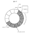
- FIG. 17 is a diagram showing the data structure of the first dummy buffer 313b.
- the first dummy buffer 313b has a ring buffer structure, which is one of the implementations of the First-In-First-Out queue.
- Each element of the first dummy buffer 313b is a process of waiting for a predetermined time tm (so-called wait process).
- the substance of the ring buffer is the structure array dummy_buffer_virtio1 [12].
- the number of elements in the array is set to 12, but the number is not limited to this.
- the above time tm is from the time when the first control software 310 calls CAN_send_virtio1 (ID, data) to the time when the CAN driver 302 stores the first peripheral transmission information 710 in the internal register 200b of the CAN controller 200a. It is the average value of the processing time. In other words, the time tm is the average value of the time until the first peripheral transmission information 710 arrives at the CAN controller 200a from the first control software 310. When the average value of the above processing times is 50 ms, the time tm in the wait process is set to 50 ms.
- the first control software 310 transmits the first interruption command to the first virtual CAN driver 313 in the above-mentioned specific situation.
- the first virtual CAN driver 313 suspends the first storage process in response to the first suspension command.
- the first virtual CAN driver 313 initializes the first buffer 313a.
- the first virtual CAN driver 313 acquires the number of the first peripheral transmission information 710 stored in the first buffer 313a before initializing the first buffer 313a. That is, the first virtual CAN driver 313 acquires the number of elements of the array in which the first peripheral transmission information 710 is stored in the first buffer 313a. For example, it is assumed that the first peripheral transmission information 710 is stored in 7 of the 12 elements. In this case, the first virtual CAN driver 313 stores the same number of wait processes in the first dummy buffer 313b.
- the first virtual CAN driver 313 stores seven wait processes in the first dummy buffer 313b. As shown in FIG. 17, the first virtual CAN driver 313 stores wait processing in each of dummy_buffer_virtio1 [0] to dummy_buffer_virtio1 [6]. Further, the first virtual CAN driver 313 assigns "0" to the index forward at the tip of the buffer and "6" to the index backward at the end of the buffer.
- control task 300 alternately takes out data from the first dummy buffer 313b and the second buffer 323a. That is, the control task 300 alternately executes the wait process (wait process of 50 ms) and the second output process.
- the first virtual CAN driver 313 may store the wait process in the first dummy buffer 313b at a predetermined first cycle in a specific situation. As a result, the first virtual CAN driver 313 simulates the timing at which the first control software 310 calls CAN_send_virtio1 (ID, data).
- the first cycle in which the first virtual CAN driver 313 stores the wait process is the average value of the time intervals in which the first control software 310 calls CAN_send_virtio1 (ID, data).
- the first cycle is not limited to a fixed cycle, and may be a value calculated according to the Poisson stochastic process using the average value of the time intervals as a parameter.
- the control task 300 Normally, the control task 300 alternately executes the first output process and the second output process. Therefore, the control task 300 executes the second output process at a substantially constant cycle.
- the control task 300 since the control task 300 continuously executes the second output process without executing the first output process (see FIG. 11), the second output process is performed. The execution cycle becomes extremely short. According to this example, since the control task 300 alternately executes the wait process and the second output process, the cycle in which the second output process is executed is maintained at a constant cycle.
- the first control software 310 is software that controls an engine in a hybrid electric vehicle (hereinafter referred to as "HEV").
- HEV hybrid electric vehicle
- the first control software 310 is software for generating torque in an engine.
- the first control software 310 transmits information related to the torque target value to be generated in the engine (opening amount of the intake valve, fuel injection amount, ignition timing, etc.) as the first peripheral transmission information 710.
- the second control software 320 is software that controls a plurality of power sources (engine and inverter motor) in the HEV.
- the second control software 320 transmits information regarding the torque target value to be generated in each of the engine and the inverter motor as the second peripheral transmission information 720.
- the HEV uses the engine as a power source for power generation and the motor as a power source for traveling.
- software for engine control and software for HEV control are mounted on one microcomputer 900. Therefore, cost reduction can be realized.
- Example 7 The configuration of the electronic control device 1000 in the seventh embodiment will be described.
- the first control software 310 is software according to QM (Quality Management) according to the functional safety standard ISO26262.
- the second control software 320 is software according to ASIL (Automotive Safety Integrity Level) -C.
- the safety standards required by the second control software 320 are higher than the safety standards required by the first control software 310.
- the second control software 320 which has a higher safety standard, can continue to transmit the second peripheral transmission information 720 to the CAN controller 200a even in a specific situation in which an abnormality occurs with respect to the first control software 310. Since the abnormality related to the first control software 310 does not affect the second control software 320, the electronic control device 1000 can realize the function of FFI (Freedom From Interference).
- FFI Freedom From Interference
- Example 8> The configuration of the electronic control device 1000 in the eighth embodiment will be described.
- the second control software 320 is configured to perform some of the processing of the first control software 310 in addition to the normal processing (transmission processing of the second peripheral transmission information 720). May be good.
- the electronic control device 1000 can maintain the processing of both the first control software 310 and the second control software 320 even when a specific situation occurs.
- the first control software 310 is software that controls the engine as described above.
- the second control software 320 is software that controls a plurality of power sources (engine and inverter motor) in the HEV as described above.
- the second control software 320 may further perform a part of the processing of the first control software 310 (output of information related to the torque target value to be generated by the engine) in a specific situation.
- the second control software 320 may reduce its functionality. For example, the second control software 320 changes the content of the data of the second peripheral transmission information 720, or changes the speed at which normal processing (transmission processing of the second peripheral transmission information 720) is executed. You may. According to the above configuration, it is possible to increase the possibility that the second control software 320 can continue the processing.
- the first control software 310 is software that controls an engine
- the second control software 320 is software that controls a plurality of power sources (engine and inverter motor) in an HEV.
- the second control software 320 may, in certain circumstances, change the target value of the torque generated by the inverter motor to a relatively small value to drive the vehicle with the minimum torque (minimum torque). That is, fail-safe driving may be performed).
- the vehicle in which the abnormality has occurred can be moved to a safe position.
- the present invention is not limited to the above-described embodiments, and various designs are designed without departing from the spirit of the present invention described in the claims. You can make changes.
- the above-described embodiment has been described in detail in order to explain the present invention in an easy-to-understand manner, and is not necessarily limited to the one including all the described configurations.
- it is possible to replace a part of the configuration of one embodiment with the configuration of another embodiment and it is also possible to add the configuration of another embodiment to the configuration of one embodiment.
Landscapes
- Engineering & Computer Science (AREA)
- Theoretical Computer Science (AREA)
- Physics & Mathematics (AREA)
- General Engineering & Computer Science (AREA)
- General Physics & Mathematics (AREA)
- Quality & Reliability (AREA)
- Debugging And Monitoring (AREA)
- Hardware Redundancy (AREA)
Abstract
本発明は、第1の制御ソフトウェアに関する異常が生じた状況においても、第2の制御ソフトウェアがペリフェラル回路を使用して処理を継続することが可能な技術を提供することを課題とする。電子制御装置は、第1の制御ソフトウェア及び第2の制御ソフトウェアを格納するメモリ(3)と、第1の制御ソフトウェア及び第2の制御ソフトウェアを実行するCPU(1)と、第1の制御ソフトウェア及び第2の制御ソフトウェアによって使用されるペリフェラル回路(200)と、を備える。メモリは、第1のバッファ(313a)と、第2のバッファ(323a)とを更に備える。CPUは、第1の制御ソフトウェアに関する異常が生じた特定状況において、第1のペリフェラル送信情報の第1のバッファへの格納処理及び第1のペリフェラル送信情報のペリフェラルへ送信処理の少なくとも一方を中断する。
Description
本開示は、電子制御装置に関する。
マイクロコンピュータ(以下、「マイコン」と称呼する)は、CPU(Central Processing Unit)、メモリ、及び、ペリフェラル等を備える。ペリフェラルは、マイコンに様々な機能を提供するために1つ以上のペリフェラル回路を含む。特許文献1は、ペリフェラルが異常状態になった場合にペリフェラルを再起動させる装置を開示している。
従来より、複数の制御ソフトウェアが搭載されたマイコンが知られている。サイズ及びコスト等の観点から、マイコン上に搭載されるペリフェラル回路の数に制限がある。従って、複数の制御ソフトウェアが1つのペリフェラル回路を共用する場合がある。
上記の構成において、複数の制御ソフトウェアのうちの一方(以下、「第1の制御ソフトウェア」と称呼する)に関する異常が生じたと仮定する。このような状況においても、複数の制御ソフトウェアのうちの他方(以下、「第2の制御ソフトウェア」と称呼する)が、ペリフェラル回路を使用して処理を継続することが求められる。特許文献1に記載された装置は、ペリフェラル回路を再起動する。このような構成の場合、第2の制御ソフトウェアは、ペリフェラル回路の再起動が完了するまでペリフェラル回路を使用することができない。従って、第2の制御ソフトウェアが処理を継続できないという課題がある。
そこで、本開示は、第1の制御ソフトウェアに関する異常が生じた状況においても、第2の制御ソフトウェアがペリフェラル回路を使用して処理を継続することが可能な技術を提供する。
一以上の実施例において、以下の電子制御装置が提供される。当該電子制御装置は、第1の制御ソフトウェア及び第2の制御ソフトウェアを格納するメモリと、前記第1の制御ソフトウェア及び前記第2の制御ソフトウェアを実行するCPUと、前記第1の制御ソフトウェア及び前記第2の制御ソフトウェアによって使用されるペリフェラル回路とを備える。前記メモリは、第1のバッファと、第2のバッファとを更に備える。前記CPUは、前記第1の制御ソフトウェアから前記ペリフェラル回路への送信情報である第1のペリフェラル送信情報を前記第1のバッファに格納する第1の格納処理と、前記第2の制御ソフトウェアから前記ペリフェラル回路への送信情報である第2のペリフェラル送信情報を前記第2のバッファに格納する第2の格納処理と、前記第1のバッファから前記ペリフェラル回路へ前記第1のペリフェラル送信情報を出力する第1の出力処理と、前記第2のバッファから前記ペリフェラル回路へ前記第2のペリフェラル送信情報を出力する第2の出力処理とを実行するように構成される。前記CPUは、前記第1の制御ソフトウェアに関する異常が生じた特定状況において、前記第1の格納処理及び前記第1の出力処理の少なくとも一方を中断し、前記第2の格納処理及び前記第2の出力処理を継続するように構成される。
上記の構成によれば、電子制御装置は、第1の制御ソフトウェアに関する異常が生じた特定状況においても、第2の制御ソフトウェアに関連する処理(第2の格納処理及び第2の出力処理)を継続することができる。本発明に関連する更なる特徴は、本明細書の記述、添付図面から明らかになるものである。また、上記した以外の、課題、構成及び効果は、以下の実施形態の説明により明らかにされる。
以下、添付図面を参照して複数の実施例について説明する。添付図面は、具体的な実施例を示しているが、本発明の技術的範囲を限定的に解釈するために用いられるものではない。
以下の複数の実施例は、それぞれ、複数の制御ソフトウェアが搭載された電子制御装置に関する。説明を簡単にするために、2つの制御ソフトウェア(第1の制御ソフトウェア及び第2の制御ソフトウェア)が搭載された電子制御装置の実施例について説明される。しかし、電子制御装置の構成は、これに限定されず、電子制御装置は、他の制御ソフトウェア(例えば、第3の制御ソフトウェア及び第4の制御ソフトウェア)を更に搭載していてもよい。
<実施例1>
(全体構成)
図1は、電子制御装置のハードウェア構成を示した図である。電子制御装置1000は、マイコン900と、電源回路901とを備える。マイコン900は、CPU1と、ペリフェラル2と、メモリ3と、バス4とを備える。CPU1、ペリフェラル2及びメモリ3は、バス4を介して互いに接続されている。従って、CPU1は、バス4を介してペリフェラル2及びメモリ3にアクセス可能である。
(全体構成)
図1は、電子制御装置のハードウェア構成を示した図である。電子制御装置1000は、マイコン900と、電源回路901とを備える。マイコン900は、CPU1と、ペリフェラル2と、メモリ3と、バス4とを備える。CPU1、ペリフェラル2及びメモリ3は、バス4を介して互いに接続されている。従って、CPU1は、バス4を介してペリフェラル2及びメモリ3にアクセス可能である。
メモリ3は、複数のソフトウェアを格納している。CPU1は、メモリ3に格納されたソフトウェアを実行する。
マイコン900は、更に、自己リセット信号出力端子911と、外部リセット端子912とを備える。自己リセット信号出力端子911及び外部リセット端子912は、それぞれ、電源回路901に接続されている。マイコン900は、自己リセット信号出力端子911を介して電源回路901にリセット要求信号を出力する。電源回路901は、リセット要求信号に応じて、外部リセット端子912に外部リセット信号を入力する。マイコン900が外部リセット信号を受け取ると、マイコン900が再起動される。
(CPU)
CPU1は、複数のコアを備える。具体的には、CPU1は、メインCPUコア100と、第1のCPUコア101と、第2のCPUコア102とを備える。
CPU1は、複数のコアを備える。具体的には、CPU1は、メインCPUコア100と、第1のCPUコア101と、第2のCPUコア102とを備える。
第1のCPUコア101は、第1のMPU(Memory Protection Unit)101aを含む。第1のMPU101aは、第1のCPUコア101がアクセス可能なメモリ3の領域(以下、「第1のアクセス可能領域」と称する)に関する設定情報を含む。第1のMPU101aは、第1のCPUコア101が第1のアクセス可能領域にアクセスすることを許可する。第1のMPU101aは、第1のCPUコア101が第1のアクセス可能領域以外の領域にアクセスすることを禁止する。
第2のCPUコア102は、第2のMPU102aを含む。第2のMPU102aは、第2のCPUコア102がアクセス可能なメモリ3の領域(以下、「第2のアクセス可能領域」と称する)に関する設定情報を含む。第2のMPU102aは、第2のCPUコア102が第2のアクセス可能領域にアクセスすることを許可する。第2のMPU102aは、第2のCPUコア102が第2のアクセス可能領域以外の領域にアクセスすることを禁止する。
メインCPUコア100は、メインOS(Operating System)301(図2を参照)に関する処理を実行する。第1のCPUコア101は、第1の制御ソフトウェア310(図2を参照)に関する処理を実行する。第2のCPUコア102は、第2の制御ソフトウェア320(図2を参照)に関する処理を実行する。
CPU1は上記の構成に限定されない。CPU1は4つ以上のCPUコアを備えてもよい。例えば、CPU1は、複数の第1のCPUコア101を備えてもよい。この場合、複数の第1のCPUコア101のそれぞれが、第1のMPU101aを含む。例えば、CPU1は、複数の第2のCPUコア102を備えてもよい。この場合、複数の第2のCPUコア102のそれぞれが、第2のMPU102aを含む。
(ペリフェラル)
ペリフェラル2は、複数のペリフェラル回路を備える。ペリフェラル回路とは、マイコン900に搭載された構成要素のうち、CPU1及びメモリ3以外の回路を指す。ペリフェラル回路の例として、例えば、CAN(Controller Area Network)コントローラ、アナログ・デジタル・コンバータ(A/Dコンバータ)、ダイレクト・メモリ・アクセスコントローラ、及び、GPIO(General Purpose Input/Output)等が挙げられる。
ペリフェラル2は、複数のペリフェラル回路を備える。ペリフェラル回路とは、マイコン900に搭載された構成要素のうち、CPU1及びメモリ3以外の回路を指す。ペリフェラル回路の例として、例えば、CAN(Controller Area Network)コントローラ、アナログ・デジタル・コンバータ(A/Dコンバータ)、ダイレクト・メモリ・アクセスコントローラ、及び、GPIO(General Purpose Input/Output)等が挙げられる。
本例において、ペリフェラル2は、共用ペリフェラル回路200と、第1のペリフェラル回路201と、第2のペリフェラル回路202とを備える。共用ペリフェラル回路200は、CANコントローラ200aを含む。第1のペリフェラル回路201は、アナログ用の第1のGPIOピン201aを含む。第2のペリフェラル回路202は、デジタル用の第2のGPIOピン202aを含む。
共用ペリフェラル回路200は、第1の制御ソフトウェア310(即ち、第1のCPUコア101)及び第2の制御ソフトウェア320(即ち、第2のCPUコア102)の両方によって使用されるペリフェラル回路である。なお、共用ペリフェラル回路200は、メインCPUコア100からもアクセスされる。
第1のペリフェラル回路201は、第1の制御ソフトウェア310(即ち、第1のCPUコア101)のみによって使用されるペリフェラル回路である。第2のペリフェラル回路202は、第2の制御ソフトウェア320(即ち、第2のCPUコア102)のみによって使用されるペリフェラル回路である。
(ソフトウェア)
図2は、メモリ3に格納されているソフトウェアを示した図である。メモリ3は、複数のソフトウェアを格納している。メモリ3は、制御タスク300と、メインOS301と、CANドライバ302とを格納している。メインCPUコア100は、これらのソフトウェア300~302を実行する。
図2は、メモリ3に格納されているソフトウェアを示した図である。メモリ3は、複数のソフトウェアを格納している。メモリ3は、制御タスク300と、メインOS301と、CANドライバ302とを格納している。メインCPUコア100は、これらのソフトウェア300~302を実行する。
メインCPUコア100によって実行される各ソフトウェアについて説明する。以降の説明において、ソフトウェア300~302が主語として記載される。しかし、ソフトウェア300~302を実行する主体はメインCPUコア100であるので、主語がメインCPUコア100に置き換えられてもよい。
メインOS301は、CANドライバ302を初期化する。CANドライバ302は、共用ペリフェラル回路200に対応するソフトウェアであり、CANコントローラ200aに動作命令を出力するソフトウェアである。
更に、メインOS301は、第1のサブOS311及び第2のサブOS321を起動する。即ち、メインOS301は、第1のサブOS311の起動命令を第1のCPUコア101に送信し、第2のサブOS321の起動命令を第2のCPUコア102に送信する。
更に、メインOS301は、1msの周期で制御タスク300を起動する。本例では、制御タスク300の実行周期が1msであるが、これに限定されない。制御タスク300の詳細な処理内容は後述する。
メモリ3は、更に、第1の制御ソフトウェア310と、第1のサブOS311と、第1のGPIOピンドライバ312と、第1の仮想CANドライバ313とを格納している。第1のCPUコア101は、これらのソフトウェア310~313を実行する。
第1のCPUコア101によって実行される各ソフトウェアについて説明する。以降の説明において、ソフトウェア310~313が主語として記載される。しかし、ソフトウェア310~313を実行する主体は第1のCPUコア101であるので、主語が第1のCPUコア101に置き換えられてもよい。
第1のサブOS311は、メインOS301からの起動命令に従い、第1のGPIOピンドライバ312を初期化する。第1のGPIOピンドライバ312は、第1のGPIOピン201aに動作命令を出力するソフトウェアである。
第1のサブOS311は、メインOS301からの起動命令に従い、第1の制御ソフトウェア310を起動する。第1の制御ソフトウェア310は、1つ以上のタスクを含む。第1の制御ソフトウェア310のタスクは、第1のサブOS311によって所定のタイミングで実行される。本例において、第1の制御ソフトウェア310は、所定のタイミングで第1のペリフェラル送信情報を送信する。第1のペリフェラル送信情報は、CANコントローラ200aへ向けて送信される情報である。
更に、第1のサブOS311は、メインOS301からの起動命令に従い、第1の仮想CANドライバ313を初期化する。第1の仮想CANドライバ313は、第1の制御ソフトウェア310とCANドライバ302との間に介在するソフトウェアであって、第1のペリフェラル送信情報を処理するソフトウェアである。具体的には、第1の仮想CANドライバ313は、第1のバッファ313aを含む。第1の仮想CANドライバ313は、第1のペリフェラル送信情報を第1のバッファ313aに格納する。
メモリ3は、更に、第2の制御ソフトウェア320と、第2のサブOS321と、第2のGPIOピンドライバ322と、第2の仮想CANドライバ323とを格納している。第2のCPUコア102は、これらのソフトウェア320~323を実行する。
第2のCPUコア102によって実行されるソフトウェアについて説明する。以降の説明において、ソフトウェア320~323が主語として記載される。しかし、ソフトウェア320~323を実行する主体は第2のCPUコア102であるので、主語が第2のCPUコア102に置き換えられてもよい。
第2のサブOS321は、メインOS301からの起動命令に従い、第2のGPIOピンドライバ322を初期化する。第2のGPIOピンドライバ322は、第2のGPIOピン202aに動作命令を出力するソフトウェアである。
第2のサブOS321は、メインOS301からの起動命令に従い、第2の制御ソフトウェア320を起動する。第2の制御ソフトウェア320は、1つ以上のタスクを含む。第2の制御ソフトウェア320のタスクは、第2のサブOS321によって所定のタイミングで実行される。本例において、第2の制御ソフトウェア320は、所定のタイミングで第2のペリフェラル送信情報を送信する。第2のペリフェラル送信情報は、CANコントローラ200aへ向けて送信される情報である。
更に、第2のサブOS321は、メインOS301からの起動命令に従い、第2の仮想CANドライバ323を初期化する。第2の仮想CANドライバ323は、第2の制御ソフトウェア320とCANドライバ302との間に介在するソフトウェアであって、第2のペリフェラル送信情報を処理するソフトウェアである。具体的には、第2の仮想CANドライバ323は、第2のバッファ323aを含む。第2の仮想CANドライバ323は、第2のペリフェラル送信情報を第2のバッファ323aに格納する。
(第1のMPUにおける設定情報)
図3は、第1のMPU101aにおける第1のアクセス可能領域に関する設定情報を示した図である。第1のCPUコア101は、ソフトウェア310~313の格納領域に対して読み取り権及び書き込み権を有する。第1のCPUコア101は、ソフトウェア310~313の格納領域以外の領域に対して読み取り権及び書き込み権を有していない。これにより、第1の制御ソフトウェア310(即ち、第1のCPUコア101)が、メインOS301及び第2の制御ソフトウェア320に影響を与えることを防止できる。
図3は、第1のMPU101aにおける第1のアクセス可能領域に関する設定情報を示した図である。第1のCPUコア101は、ソフトウェア310~313の格納領域に対して読み取り権及び書き込み権を有する。第1のCPUコア101は、ソフトウェア310~313の格納領域以外の領域に対して読み取り権及び書き込み権を有していない。これにより、第1の制御ソフトウェア310(即ち、第1のCPUコア101)が、メインOS301及び第2の制御ソフトウェア320に影響を与えることを防止できる。
(第2のMPUにおける設定情報)
図4は、第2のMPU102aにおける第2のアクセス可能領域に関する設定情報を示した図である。第2のCPUコア102は、ソフトウェア320~323の格納領域に対して読み取り権及び書き込み権を有する。第2のCPUコア102は、ソフトウェア320~323の格納領域以外の領域に対して読み取り権及び書き込み権を有していない。これにより、第2の制御ソフトウェア320(即ち、第2のCPUコア102)が、メインOS301及び第1の制御ソフトウェア310に影響を与えることを防止できる。
図4は、第2のMPU102aにおける第2のアクセス可能領域に関する設定情報を示した図である。第2のCPUコア102は、ソフトウェア320~323の格納領域に対して読み取り権及び書き込み権を有する。第2のCPUコア102は、ソフトウェア320~323の格納領域以外の領域に対して読み取り権及び書き込み権を有していない。これにより、第2の制御ソフトウェア320(即ち、第2のCPUコア102)が、メインOS301及び第1の制御ソフトウェア310に影響を与えることを防止できる。
なお、メインCPUコア100は、メモリ3の全ての領域にアクセスすることができる。
(外部の制御装置との接続構成)
図5は、電子制御装置1000と外部機器との接続関係を示した図である。以下では、第1の制御ソフトウェア310及び第2の制御ソフトウェア320のそれぞれの処理内容について説明する。
図5は、電子制御装置1000と外部機器との接続関係を示した図である。以下では、第1の制御ソフトウェア310及び第2の制御ソフトウェア320のそれぞれの処理内容について説明する。
・第1の制御ソフトウェア
複数のセンサ511及び複数のアクチュエータ512は、電子制御装置1000の外部に配置されている。複数のセンサ511及び複数のアクチュエータ512は、それぞれ、第1のGPIOピン201aに接続されている。
複数のセンサ511及び複数のアクチュエータ512は、電子制御装置1000の外部に配置されている。複数のセンサ511及び複数のアクチュエータ512は、それぞれ、第1のGPIOピン201aに接続されている。
第1の制御ソフトウェア310は、第1のGPIOピン201aにアクセスして、複数のアクチュエータ512のそれぞれに対してアナログ信号を入力する。更に、第1の制御ソフトウェア310は、第1のGPIOピン201aを介して、複数のセンサ511のそれぞれからアナログ信号を受け取る。第1の制御ソフトウェア310は、これらのアナログ信号に基づいて、第1のペリフェラル送信情報を送信する。
本例において、第1のペリフェラル送信情報は、第1の制御ソフトウェア310から他の電子制御装置540のそれぞれに対して送信されるCANメッセージである。なお、第1のペリフェラル送信情報は、後述するように、第1のバッファ313aを介して、CANコントローラ200aに出力される。CANコントローラ200aは、第1のペリフェラル送信情報を受け取る。CANコントローラ200aは、第1のペリフェラル送信情報を物理的信号に変換し、当該物理的信号をCANバス530を介して他の電子制御装置540に対して送信する。
・第2の制御ソフトウェア
複数のセンサ521及び複数のアクチュエータ522は、電子制御装置1000の外部に配置されている。複数のセンサ521及び複数のアクチュエータ522は、それぞれ、第2のGPIOピン202aに接続されている。
複数のセンサ521及び複数のアクチュエータ522は、電子制御装置1000の外部に配置されている。複数のセンサ521及び複数のアクチュエータ522は、それぞれ、第2のGPIOピン202aに接続されている。
第2の制御ソフトウェア320は、第2のGPIOピン202aにアクセスして、複数のアクチュエータ522のそれぞれに対してデジタル信号を入力する。更に、第2の制御ソフトウェア320は、第2のGPIOピン202aを介して、複数のセンサ521のそれぞれからデジタル信号を受け取る。第2の制御ソフトウェア320は、これらのデジタル信号に基づいて、第2のペリフェラル送信情報を送信する。
本例において、第2のペリフェラル送信情報は、第2の制御ソフトウェア320から他の電子制御装置540のそれぞれに対して送信されるCANメッセージである。なお、第2のペリフェラル送信情報は、後述するように、第2のバッファ323aを介して、CANコントローラ200aに出力される。CANコントローラ200aは、第2のペリフェラル送信情報を受け取る。CANコントローラ200aは、第2のペリフェラル送信情報を物理的信号に変換し、当該物理的信号をCANバス530を介して他の電子制御装置540に対して送信する。
(CANドライバ及びCANコントローラの動作)
図6は、CANドライバ302の動作及びCANコントローラ200aの動作の概要を示した図である。以下では、第1の制御ソフトウェア310が第1のペリフェラル送信情報を送信した場合について説明する。CANドライバ302は、CANコントローラ200aの内部レジスタ200bの所定の場所に第1のペリフェラル送信情報を格納する。CANコントローラ200aは、第1のペリフェラル送信情報を所定のCANプロトコルに従いCANフレーム600に格納する。そして、CANコントローラ200aは、CANフレーム600を物理的信号に変換してCANバス530に送信する。
図6は、CANドライバ302の動作及びCANコントローラ200aの動作の概要を示した図である。以下では、第1の制御ソフトウェア310が第1のペリフェラル送信情報を送信した場合について説明する。CANドライバ302は、CANコントローラ200aの内部レジスタ200bの所定の場所に第1のペリフェラル送信情報を格納する。CANコントローラ200aは、第1のペリフェラル送信情報を所定のCANプロトコルに従いCANフレーム600に格納する。そして、CANコントローラ200aは、CANフレーム600を物理的信号に変換してCANバス530に送信する。
なお、第2の制御ソフトウェア320が第2のペリフェラル送信情報を送信した場合についても、CANドライバ302及びCANコントローラ200aは、上記と同じように動作する。
(ソフトウェアの動作)
図7は、複数のソフトウェア間の入力/出力の関係を示した図である。本例によれば、CANドライバ302の前段に、2つの仮想的なCANドライバ(即ち、第1の仮想CANドライバ313及び第2の仮想CANドライバ323)が存在する。第1の制御ソフトウェア310及び第2の制御ソフトウェア320が、それぞれ、第1の仮想CANドライバ313及び第2の仮想CANドライバ323を使用する。制御タスク300は、第1の仮想CANドライバ313及び第2の仮想CANドライバ323に交互にアクセスして、第1のペリフェラル送信情報710及び第2のペリフェラル送信情報720を交互にCANドライバ302に出力する。これにより、第1の制御ソフトウェア310の処理と第2の制御ソフトウェア320の処理とを分離しながら、1つのCANドライバ302を使用することができる。
図7は、複数のソフトウェア間の入力/出力の関係を示した図である。本例によれば、CANドライバ302の前段に、2つの仮想的なCANドライバ(即ち、第1の仮想CANドライバ313及び第2の仮想CANドライバ323)が存在する。第1の制御ソフトウェア310及び第2の制御ソフトウェア320が、それぞれ、第1の仮想CANドライバ313及び第2の仮想CANドライバ323を使用する。制御タスク300は、第1の仮想CANドライバ313及び第2の仮想CANドライバ323に交互にアクセスして、第1のペリフェラル送信情報710及び第2のペリフェラル送信情報720を交互にCANドライバ302に出力する。これにより、第1の制御ソフトウェア310の処理と第2の制御ソフトウェア320の処理とを分離しながら、1つのCANドライバ302を使用することができる。
具体的には、第1の制御ソフトウェア310は、第1のペリフェラル送信情報710を第1の仮想CANドライバ313に送信する。第1の仮想CANドライバ313は、第1のペリフェラル送信情報710を第1のバッファ313aに格納する。
第2の制御ソフトウェア320は、第2のペリフェラル送信情報720を第2の仮想CANドライバ323に送信する。第2の仮想CANドライバ323は、第2のペリフェラル送信情報720を第2のバッファ323aに格納する。
制御タスク300は、第1のバッファ313aから第1のペリフェラル送信情報710を取り出し、第1のペリフェラル送信情報710をCANドライバ302に出力する。
制御タスク300は、第2のバッファ323aから第2のペリフェラル送信情報720を取り出し、第2のペリフェラル送信情報720をCANドライバ302に出力する。
以下、図7に示した各種ソフトウェアの具体的な処理内容について説明する。
・第1の制御ソフトウェア
図8は、第1の制御ソフトウェア310が第1のペリフェラル送信情報710を送信する場合の処理の流れを説明する図である。第1の制御ソフトウェア310は、第1のペリフェラル送信情報710として、CANメッセージID及びデータを指定する。第1の制御ソフトウェア310は、CAN_send_virtio1(ID, data)をコールする。CAN_send_virtio1(ID, data)は、第1のペリフェラル送信情報710を第1の仮想CANドライバ313へ送信するコマンドである。第1のペリフェラル送信情報710は、CANメッセージID711及びデータ712を含む。
図8は、第1の制御ソフトウェア310が第1のペリフェラル送信情報710を送信する場合の処理の流れを説明する図である。第1の制御ソフトウェア310は、第1のペリフェラル送信情報710として、CANメッセージID及びデータを指定する。第1の制御ソフトウェア310は、CAN_send_virtio1(ID, data)をコールする。CAN_send_virtio1(ID, data)は、第1のペリフェラル送信情報710を第1の仮想CANドライバ313へ送信するコマンドである。第1のペリフェラル送信情報710は、CANメッセージID711及びデータ712を含む。
・第1の仮想CANドライバ
第1の制御ソフトウェア310がCAN_send_virtio1(ID, data)をコールすると、第1の仮想CANドライバ313は、第1のペリフェラル送信情報710を受け取る。第1の仮想CANドライバ313は、第1のペリフェラル送信情報710を第1のバッファ313aに格納する。
第1の制御ソフトウェア310がCAN_send_virtio1(ID, data)をコールすると、第1の仮想CANドライバ313は、第1のペリフェラル送信情報710を受け取る。第1の仮想CANドライバ313は、第1のペリフェラル送信情報710を第1のバッファ313aに格納する。
・第2の制御ソフトウェア
第2の制御ソフトウェア320が第2のペリフェラル送信情報720を送信する場合についても同様である。第2の制御ソフトウェア320は、第2のペリフェラル送信情報720として、CANメッセージID及びデータを指定する。第2の制御ソフトウェア320は、CAN_send_virtio2(ID, data)をコールする。CAN_send_virtio2(ID, data)は、第2のペリフェラル送信情報720を第2の仮想CANドライバ323へ送信するコマンドである。図7に示すように、第2のペリフェラル送信情報720は、CANメッセージID721及びデータ722を含む。
第2の制御ソフトウェア320が第2のペリフェラル送信情報720を送信する場合についても同様である。第2の制御ソフトウェア320は、第2のペリフェラル送信情報720として、CANメッセージID及びデータを指定する。第2の制御ソフトウェア320は、CAN_send_virtio2(ID, data)をコールする。CAN_send_virtio2(ID, data)は、第2のペリフェラル送信情報720を第2の仮想CANドライバ323へ送信するコマンドである。図7に示すように、第2のペリフェラル送信情報720は、CANメッセージID721及びデータ722を含む。
・第2の仮想CANドライバ
第2の制御ソフトウェア320がCAN_send_virtio2(ID, data)をコールすると、第2の仮想CANドライバ323は、第2のペリフェラル送信情報720を受け取る。第2の仮想CANドライバ323は、第2のバッファ323aに第2のペリフェラル送信情報720を格納する。
第2の制御ソフトウェア320がCAN_send_virtio2(ID, data)をコールすると、第2の仮想CANドライバ323は、第2のペリフェラル送信情報720を受け取る。第2の仮想CANドライバ323は、第2のバッファ323aに第2のペリフェラル送信情報720を格納する。
・第1のバッファ
図9は、第1のバッファ313aのデータ構造を示した図である。第1のバッファ313aは、First-In-First-Outキューの実装の1つであるリングバッファ構造を有する。第1のバッファ313aの各要素は、CANメッセージIDとデータの組からなる構造体である。リングバッファの実体は、構造体配列buffer_virtio1[12]である。なお、ここでは説明の都合上、配列の要素数を12としているが、これに限定されない。
図9は、第1のバッファ313aのデータ構造を示した図である。第1のバッファ313aは、First-In-First-Outキューの実装の1つであるリングバッファ構造を有する。第1のバッファ313aの各要素は、CANメッセージIDとデータの組からなる構造体である。リングバッファの実体は、構造体配列buffer_virtio1[12]である。なお、ここでは説明の都合上、配列の要素数を12としているが、これに限定されない。
第1の制御ソフトウェア310がCAN_send_virtio1(ID, data)をコールすると、第1の仮想CANドライバ313は、バッファ終端位置を表すインデックスbackwardを以下のように演算する(backward←(backward + 1) % 12)。ここで、「%」は、(backward + 1)を12で割ったときの余りを求める演算子である。なお、インデックスbackwardが配列終端(backward = 11)である場合、第1の仮想CANドライバ313は、backwardに「0」を代入する。第1の仮想CANドライバ313は、第1のペリフェラル送信情報710をbuffer_virtio1[backward]に格納する。このように、第1の仮想CANドライバ313は、第1のペリフェラル送信情報710を第1のバッファ313aの最後尾に格納する。以降において、このような第1のペリフェラル送信情報710の格納処理は、「第1の格納処理」と称呼される。
・第2のバッファ
図10は、第2のバッファ323aのデータ構造を示した図である。第2のバッファ323aは、First-In-First-Outキューの実装の1つであるリングバッファ構造を有する。第2のバッファ323aの各要素はCANメッセージIDとデータの組からなる構造体である。リングバッファの実体は、構造体配列buffer_virtio2[12]である。なお、ここでは説明の都合上、配列の要素数を12としているが、これに限定されない。
図10は、第2のバッファ323aのデータ構造を示した図である。第2のバッファ323aは、First-In-First-Outキューの実装の1つであるリングバッファ構造を有する。第2のバッファ323aの各要素はCANメッセージIDとデータの組からなる構造体である。リングバッファの実体は、構造体配列buffer_virtio2[12]である。なお、ここでは説明の都合上、配列の要素数を12としているが、これに限定されない。
第2の制御ソフトウェア320がCAN_send_virtio2(ID, data)をコールすると、第2の仮想CANドライバ323は、バッファ終端位置を表すインデックスbackwardを以下のように演算する(backward←(backward + 1) % 12)。なお、インデックスbackwardが配列終端(backward = 11)である場合、第2の仮想CANドライバ323は、backwardに「0」を代入する。第2の仮想CANドライバ323は、第2のペリフェラル送信情報720をbuffer_virtio2[backward]に格納する。このように、第2の仮想CANドライバ323は、第2のペリフェラル送信情報720を第2のバッファ323aの最後尾に格納する。以降において、このような第2のペリフェラル送信情報720の格納処理は、「第2の格納処理」と称呼される。
・制御タスク
制御タスク300は、第1のバッファ313aから第1のペリフェラル送信情報710を取り出す。図9に示すように、制御タスク300は、バッファ先頭位置を示すインデックスforwardに含まれたデータbuffer_virtio1[forward]を、第1のペリフェラル送信情報710として取り出す。そして、制御タスク300は、インデックスforwardを以下のように演算する(forward ← (forward + 1) % 12)。なお、インデックスforwardが配列終端(forward = 11)である場合、制御タスク300は、インデックスforwardに「0」を代入する。制御タスク300は、第1のペリフェラル送信情報710をCANドライバ302に出力する。以降において、このような第1のペリフェラル送信情報710の出力処理は、「第1の出力処理」と称呼される。
制御タスク300は、第1のバッファ313aから第1のペリフェラル送信情報710を取り出す。図9に示すように、制御タスク300は、バッファ先頭位置を示すインデックスforwardに含まれたデータbuffer_virtio1[forward]を、第1のペリフェラル送信情報710として取り出す。そして、制御タスク300は、インデックスforwardを以下のように演算する(forward ← (forward + 1) % 12)。なお、インデックスforwardが配列終端(forward = 11)である場合、制御タスク300は、インデックスforwardに「0」を代入する。制御タスク300は、第1のペリフェラル送信情報710をCANドライバ302に出力する。以降において、このような第1のペリフェラル送信情報710の出力処理は、「第1の出力処理」と称呼される。
制御タスク300は、第2のバッファ323aから第2のペリフェラル送信情報720を取り出す。図10に示すように、制御タスク300は、バッファ先頭位置を示すインデックスforwardに含まれたデータbuffer_virtio2[forward]を、第2のペリフェラル送信情報720として取り出す。そして、制御タスク300は、インデックスforwardを以下のように演算する(forward ← (forward + 1) % 12)。なお、インデックスforwardが配列終端(forward = 11)である場合、制御タスク300は、インデックスforwardに「0」を代入する。制御タスク300は、第2のペリフェラル送信情報720をCANドライバ302に出力する。以降において、このような第2のペリフェラル送信情報720の出力処理は、「第2の出力処理」と称呼される。
図11は、制御タスク300の内部に保持される状態遷移図である。制御タスク300は、上述のように、メインOS301によって1msの周期で起動されるタスクである。制御タスク300は、第1の出力処理及び第2の出力処理を交互に実行する。
例えば、いま、制御タスク300が第1状態St1であると仮定する。この場合、制御タスク300は、第1の出力処理を実行する。
制御タスク300は、第1の出力処理を実行した後に、第2のバッファ323aが空であるか否かを判定する。第2のバッファ323aが空でない場合は、制御タスク300は、第1状態St1から第2状態St2へと遷移する。一方、第2のバッファ323aが空であり且つ第1のバッファ313aが空でない場合(即ち、第2のバッファ323aのみが空である場合)、制御タスク300は第1状態St1を維持する。この場合、制御タスク300は、第1の出力処理を繰り返し実行する。
なお、制御タスク300が第1の出力処理を実行した後に、第1のバッファ313a及び第2のバッファ323aの両方が空である場合、制御タスク300は、第1状態St1から第3状態St3へと遷移する。この場合、制御タスク300は、何も動作をしない。その後、第1のバッファ313aが空でない場合(即ち、第1のペリフェラル送信情報710が第1のバッファ313aに格納された場合)、制御タスク300は、第3状態St3から第1状態St1へと遷移する。或いは、第2のバッファ323aが空でない場合(即ち、第2のペリフェラル送信情報720が第2のバッファ323aに格納された場合)、制御タスク300は、第3状態St3から第2状態St2へと遷移する。
制御タスク300が、第1状態St1から第2状態St2に遷移したと仮定する。この場合、制御タスク300は、第2の出力処理を実行する。
制御タスク300は、第2の出力処理を実行した後に、第1のバッファ313aが空であるか否かを判定する。第1のバッファ313aが空でない場合は、制御タスク300は、第2状態St2から第1状態St1へと遷移する。一方、第1のバッファ313aが空であり且つ第2のバッファ323aが空でない場合(即ち、第1のバッファ313aのみが空である場合)、制御タスク300は第2状態St2を維持する。この場合、制御タスク300は、第2の出力処理を繰り返し実行する。
なお、制御タスク300が第2の出力処理を実行した後に、第1のバッファ313a及び第2のバッファ323aの両方が空である場合、制御タスク300は、第1状態St1から第3状態St3へと遷移する。この場合、制御タスク300は、何も動作をしない。その後、第1のバッファ313aが空でない場合(即ち、第1のペリフェラル送信情報710が第1のバッファ313aに格納された場合)、制御タスク300は、第3状態St3から第1状態St1へと遷移する。或いは、第2のバッファ323aが空でない場合(即ち、第2のペリフェラル送信情報720が第2のバッファ323aに格納された場合)、制御タスク300は、第3状態St3から第2状態St2へと遷移する。
(本実施例の特徴)
電子制御装置1000において、第1の制御ソフトウェア310に関する異常が生じ得る。以下、このような状況は、「特定状況」と称呼される。特定状況は、例えば、第1の制御ソフトウェア310に異常が生じた状況、並びに、第1の制御ソフトウェア310に関するソフトウェア及びハードウェアに異常が生じた状況を含む。
電子制御装置1000において、第1の制御ソフトウェア310に関する異常が生じ得る。以下、このような状況は、「特定状況」と称呼される。特定状況は、例えば、第1の制御ソフトウェア310に異常が生じた状況、並びに、第1の制御ソフトウェア310に関するソフトウェア及びハードウェアに異常が生じた状況を含む。
本例において、特定状況は、以下の(1)~(3)のうちの少なくとも1つが生じた状況を意味する。
(1)第1の制御ソフトウェア310が通常の処理以外の処理(所謂、例外処理)を実行する。ここで、通常の処理は、第1のペリフェラル送信情報710の送信処理である。例外処理は、例えば、第1のアクセス可能領域以外へのアクセス(領域外アクセス)、及び、デッドラインミスに関する処理等を含む。
(2)第1の制御ソフトウェア310に関連するソフトウェア(例えば、第1のGPIOピンドライバ312)に異常が生じた。
(3)第1の制御ソフトウェア310に関連するハードウェアに異常が生じた。このようなハードウェアとして、(a)CPU1及びメモリ3、(b)第1のGPIOピン201aに接続されたセンサ511及びアクチュエータ522、並びに、(c)第1のペリフェラル送信情報710の送信先である共用ペリフェラル回路200等が挙げられる。
第1の制御ソフトウェア310は、特定状況において、第1の中断指令を第1の仮想CANドライバ313に送信する。第1の中断指令は、第1の格納処理を中断する指令、及び、第1のバッファ313aを初期化する指令を含む。第1の仮想CANドライバ313は、第1の中断指令に応じて、第1の格納処理を中断する(禁止する)。更に、第1の仮想CANドライバ313は、第1の中断指令に応じて、第1のバッファ313aを初期化する(即ち、第1のバッファ313aを空にする)。第1の仮想CANドライバ313は、バッファ終端位置を示すインデックスbackwardにバッファ先頭位置を示すインデックスforwardを代入することにより、第1のバッファ313aを初期化することができる。
このように、第1の仮想CANドライバ313は、第1の中断指令に応じて、第1の格納処理を中断し、第1のバッファ313aを初期化する。第1のバッファ313aが空になるので、制御タスク300は、第2状態St2を維持する(図11を参照)。他の言い方をすれば、制御タスク300は、第1の出力処理を中断する。一方、制御タスク300は、第2の格納処理及び第2の出力処理を継続する。
本実施例によれば、CANドライバ302の前段に、2つの仮想的なCANドライバ313及び323が存在する。第1の制御ソフトウェア310及び第2の制御ソフトウェア320が、それぞれ、第1の仮想CANドライバ313及び第2の仮想CANドライバ323を使用する。制御タスク300は、第1の仮想CANドライバ313及び第2の仮想CANドライバ323に交互にアクセスして、第1のペリフェラル送信情報710及び第2のペリフェラル送信情報720を交互にCANドライバ302に出力する。このように、第1の制御ソフトウェア310の処理と第2の制御ソフトウェア320の処理とが分離される。従って、第1の制御ソフトウェア310に関する異常が生じた特定状況においても、第2の制御ソフトウェア320が、第2の格納処理及び第2の出力処理を継続できる。即ち、第2の制御ソフトウェア320が、第2のペリフェラル送信情報720のCANコントローラ200aへの送信を継続することができる。
更に、特定状況において、不適切な第1のペリフェラル送信情報710がCANドライバ302に出力される可能性がある。第1の仮想CANドライバ313は、第1のバッファ313aを初期化するので、上記のような問題が生じるのを防ぐことができる。
本例においては、第1のCPUコア101が第1の制御ソフトウェア310に関する処理を実行し、第2のCPUコア102が第2の制御ソフトウェア320に関する処理を実行する。従って、2つのCPUコア101及び102が互いに独立して処理を継続できる。一方のCPUコアによって実行される処理が、他方のCPUコアによって実行される処理に影響を与えることを防ぐことができる。
なお、第2の制御ソフトウェア320に関する異常が生じた場合でも同様の処理が実行される。第2の制御ソフトウェア320は、第2の中断指令を第2の仮想CANドライバ323に送信する。第2の中断指令は、第2の格納処理を中断する指令、及び、第2のバッファ323aを初期化する指令を含む。第2の仮想CANドライバ323は、第2の中断指令に応じて、第2の格納処理を中断する(禁止する)。更に、第2の仮想CANドライバ323は、第2のバッファ323aを初期化する。第2の仮想CANドライバ323は、バッファ終端位置を示すインデックスbackwardにバッファ先頭位置を示すインデックスforwardを代入することにより、第2のバッファ323aを初期化することができる。
<実施例2>
実施例2における電子制御装置1000の構成について説明する。以下では、実施例1との違いを中心に説明する。図12は、本例における複数のソフトウェア間の入力/出力の関係を示した図である。制御タスク300は、第1の格納処理、第2の格納処理、第1の出力処理及び第2の出力処理の全てを実行するように構成される。
実施例2における電子制御装置1000の構成について説明する。以下では、実施例1との違いを中心に説明する。図12は、本例における複数のソフトウェア間の入力/出力の関係を示した図である。制御タスク300は、第1の格納処理、第2の格納処理、第1の出力処理及び第2の出力処理の全てを実行するように構成される。
制御タスク300は、第1の制御ソフトウェア310から第1のペリフェラル送信情報710を受け取り、第1の格納処理を実行する。更に、制御タスク300は、第2の制御ソフトウェア320から第2のペリフェラル送信情報720を受け取り、第2の格納処理を実行する。
制御タスク300は、図11の状態遷移図に従って、第1の出力処理及び第2の出力処理を実行する。
第1の制御ソフトウェア310は、特定状況において、第3の中断指令を制御タスク300に送信する。第3の中断指令は、第1の格納処理を中断する指令のみを含む。制御タスク300は、第3の中断指令に応じて、第1の格納処理を中断する。制御タスク300は、第1のバッファ313aが空になるまで第1の出力処理を継続する。第1のバッファ313aが空になると、制御タスク300は、第1の出力処理を中断する。一方、制御タスク300は、第2の格納処理及び第2の出力処理を継続する。
上記の構成によれば、特定状況においても、第2の制御ソフトウェア320が、第2の格納処理及び第2の出力処理を継続できる。
別の例において、第3の中断指令は、第1の出力処理を中断する指令のみを含む。制御タスク300は、第3の中断指令に応じて、第1の出力処理を中断する。制御タスク300は、第1の格納処理のみを継続してもよい。制御タスク300は、第1のバッファ313aの配列の要素の全てが埋まるまで、第1の格納処理を継続してもよい。第1のバッファ313aの配列の要素の全てが埋まると、制御タスク300は、第1の格納処理を中断する。一方、制御タスク300は、第2の格納処理及び第2の出力処理を継続する。
更に別の例において、制御タスク300は、特定状況において第1の格納処理及び第1の出力処理の両方を中断してもよい。従って、第1のバッファ313a内の第1のペリフェラル送信情報710が保持(ホールド)される。
<実施例3>
実施例3における電子制御装置1000の構成について説明する。以下では、実施例1との違いを中心に説明する。図13に示すように、本例において、メモリ3は、初期化タスク304と、診断タスク305とを更に格納している。メインCPUコア100は、これらのソフトウェア304及び305を更に実行する。実施例1と同様の構成については、同一の符号を付してその説明を省略する。
実施例3における電子制御装置1000の構成について説明する。以下では、実施例1との違いを中心に説明する。図13に示すように、本例において、メモリ3は、初期化タスク304と、診断タスク305とを更に格納している。メインCPUコア100は、これらのソフトウェア304及び305を更に実行する。実施例1と同様の構成については、同一の符号を付してその説明を省略する。
メインOS301は、CANドライバ302を初期化する。メインOS301は、1msの周期で制御タスク300及び初期化タスク304を起動する。本例では、制御タスク300及び初期化タスク304の実行周期が1msであるが、これに限定されない。
更に、メインOS301は、10msの周期で診断タスク305を起動する。本例では、診断タスク305の実行周期が10msであるが、これに限定されない。
(診断情報テーブル)
図14は、診断タスク305が生成する診断情報テーブル1400の例である。診断情報テーブル1400は、構成項目として、診断対象1401と、状態1402とを含む。診断対象1401は、診断の対象となるハードウェア又はソフトウェアである。状態1402は、診断対象1401が正常な状態又は異常な状態であるかを表す情報である。
図14は、診断タスク305が生成する診断情報テーブル1400の例である。診断情報テーブル1400は、構成項目として、診断対象1401と、状態1402とを含む。診断対象1401は、診断の対象となるハードウェア又はソフトウェアである。状態1402は、診断対象1401が正常な状態又は異常な状態であるかを表す情報である。
診断タスク305は、10msの周期で、診断情報テーブル1400の診断対象1401のそれぞれが正常に動作しているかを監視する。それに応じて、診断タスク305は、診断情報テーブル1400の状態1402を更新する。
例えば、診断タスク305は、電子制御装置1000のハードウェアが正常に動作しているかを確認する。ここでのハードウェアは、メインCPUコア100、第1のCPUコア101、第2のCPUコア102、CANコントローラ200a、第1のGPIOピン201a及び第2のGPIOピン202aを含む。
更に、診断タスク305は、第1のアクセス可能領域(第1のCPUコア101がアクセスできるメモリ3の領域)及び第2のアクセス可能領域(第2のCPUコア102がアクセスできるメモリ3の領域)にメモリエラーが発生していないかを確認する。メモリエラーは、パリティチェック及びCRC(Cyclic Redundancy Check)等の方法で検出されてもよいし、これ以外の方法で検出されてもよい。
診断タスク305は、第1の制御ソフトウェア310が正常に動作しているかを確認する。診断タスク305は、第1の制御ソフトウェア310が例外処理を実行している場合、第1の制御ソフトウェア310に異常が生じていると判定してもよい。更に、診断タスク305は、第2の制御ソフトウェア320が正常に動作しているかを確認する。
診断タスク305は、診断対象1401が正常に動作していると判定した場合、対応する状態1402を「正常」に設定する。診断タスク305は、診断対象1401に異常が生じていると判定した場合、対応する状態1402を「異常」に設定する。これにより、初期化タスク304は、診断情報テーブル1400を参照することにより、診断対象1401のそれぞれが正常に動作しているか否かを確認することができる。
なお、診断情報テーブル1400は、上記の例に限定されない。診断タスク305は、第1のサブOS311及び第2のサブOS321がそれぞれ正常に動作しているかを確認してもよい。
図15は、初期化タスク304が保持する初期化ポリシーテーブル1500の例である。初期化ポリシーテーブル1500は、構成項目として、異常が生じている対象1501と、初期化ポリシー1502とを含む。初期化ポリシー1502は、どの初期化処理を実行するかを表す。本例において、初期化処理は、全体初期化処理、第1の初期化処理、及び、第2の初期化処理を含む。
初期化タスク304は、診断情報テーブル1400を参照することにより、診断対象1401に異常が生じているかを判定する。診断対象1401に異常が生じている場合、初期化タスク304は、初期化ポリシーテーブル1500を参照することにより、その診断対象(即ち、異常が生じている対象1501)に対応する初期化ポリシー1502を取得する。初期化タスク304は、当該取得した初期化ポリシー1502に従って、初期化処理を実行する。
メインCPUコア100に異常が生じている場合、初期化タスク304は、全体初期化処理を実行する。更に、CANコントローラ200aに異常が生じている場合、初期化タスク304は、全体初期化処理を実行する。
一方、「第1のCPUコア101に関連するハードウェア及びソフトウェア1510」に異常が生じている場合、初期化タスク304は、第1の初期化処理を実行する。
更に、「第2のCPUコア102に関連するハードウェア及びソフトウェア1520」に異常が生じている場合、初期化タスク304は、第2の初期化処理を実行する。
図16は、初期化タスク304が保持する初期化範囲テーブル1600の例である。初期化範囲テーブル1600は、各初期化処理が、どのハードウェア及びソフトウェアを初期化するかを表す。
全体初期化処理は、全てのハードウェア及びソフトウェアを初期化する処理である。初期化タスク304は、以下のように全体初期化処理を実行する。初期化タスク304は、自己リセット信号出力端子911を介して電源回路901にリセット要求信号を出力する。電源回路901は、リセット要求信号に応じて、外部リセット端子912に外部リセット信号を入力する。マイコン900が外部リセット信号を受け取ると、マイコン900が再起動される。このように、マイコン900上の全てのハードウェア及びソフトウェアが初期化される。
第1の初期化処理は、第1のCPUコア101に関連するハードウェア及びソフトウェアを初期化する処理である。初期化タスク304は、以下のように第1の初期化処理を実行する。初期化タスク304は、第1のCPUコア101を再起動する。更に、初期化タスク304は、第1のサブOS311を再起動する。その後、初期化タスク304は、第1のサブOS311に所定の起動命令を送信する。第1のサブOS311は、初期化タスク304からの起動命令に従い、第1のGPIOピンドライバ312を初期化する。更に、第1のサブOS311は、第1の仮想CANドライバ313を初期化する。これにより、第1のバッファ313aが空になる。更に、第1のサブOS311は、第1の制御ソフトウェア310を再起動する。更に、第1のサブOS311は、第1のアクセス可能領域を初期化する。
第2の初期化処理は、第2のCPUコア102に関連するハードウェア及びソフトウェアを初期化する処理である。初期化タスク304は、以下のように第2の初期化処理を実行する。初期化タスク304は、第2のCPUコア102を再起動する。更に、初期化タスク304は、第2のサブOS321を再起動する。その後、初期化タスク304は、第2のサブOS321に所定の起動命令を送信する。第2のサブOS321は、初期化タスク304からの起動命令に従い、第2のGPIOピンドライバ322を初期化する。更に、第2のサブOS321は、第2の仮想CANドライバ323を初期化する。これにより、第2のバッファ323aが空になる。更に、第2のサブOS321は、第2の制御ソフトウェア320を再起動する。更に、第2のサブOS321は、第2のアクセス可能領域を初期化する。
以上のように、初期化タスク304は、異常が生じたハードウェア及びソフトウェアに応じて、初期化するハードウェア及びソフトウェアを変更する。例えば、第1のCPUコア101に関連するハードウェア及びソフトウェア1510(図15を参照)に異常が生じている場合、初期化タスク304は、第1の初期化処理を実行する。初期化タスク304は、第1のCPUコア101に関連するハードウェア及びソフトウェア1510のみを初期化することができる。第1の初期化処理が実行されている間、第1の格納処理及び第1の出力処理は中断される。一方、第1の初期化処理が実行されている間、第2の仮想CANドライバ323は第2の格納処理を継続し、制御タスク300は第2の出力処理を継続する。従って、第2の制御ソフトウェア320が、第2のペリフェラル送信情報720のCANコントローラ200aへの送信を継続することができる。
第2のCPUコア102に関連するハードウェア及びソフトウェア1520(図15を参照)に異常が生じている場合、初期化タスク304は、第2の初期化処理を実行する。初期化タスク304は、第2のCPUコア102に関連するハードウェア及びソフトウェア1520のみを初期化することができる。第2の初期化処理が実行されている間、第2の格納処理及び第2の出力処理は中断される。一方、第2の初期化処理が実行されている間、第1の仮想CANドライバ313は第1の格納処理を継続し、制御タスク300は第1の出力処理を継続する。従って、第1の制御ソフトウェア310が、第1のペリフェラル送信情報710のCANコントローラ200aへの送信を継続することができる。
<実施例4>
実施例4における電子制御装置1000の構成について説明する。以下では、実施例3との違いを中心に説明する。メモリ3は、第1の初期化処理フラグを管理する領域と、第2の初期化処理フラグを管理する領域とを備える。
実施例4における電子制御装置1000の構成について説明する。以下では、実施例3との違いを中心に説明する。メモリ3は、第1の初期化処理フラグを管理する領域と、第2の初期化処理フラグを管理する領域とを備える。
第1の初期化処理フラグは、第1のアクセス可能領域において管理される。第1の初期化処理フラグは、True又はFalseのいずれかの値を取る。第1の初期化処理フラグは、第1の初期化処理が実行されている期間において、Trueの値である。第1の初期化処理フラグは、第1の初期化処理が実行されていない期間において、Falseの値である。
第1の初期化処理フラグがFalseの場合、第1の仮想CANドライバ313は第1の格納処理を実行し、制御タスク300は第1の出力処理を実行する。初期化タスク304は、第1の初期化処理を開始する際に、第1の初期化処理フラグをTrueに設定する。従って、第1の仮想CANドライバ313は第1の格納処理を中断し、制御タスク300は第1の出力処理を中断する。初期化タスク304は、第1の初期化処理が完了した際に、第1の初期化処理フラグをFalseに設定する。従って、第1の仮想CANドライバ313は第1の格納処理を再開し、制御タスク300は第1の出力処理を再開する。上記の構成によれば、第1の初期化処理の完了に応じて、第1の格納処理及び第1の出力処理を再開させることができる。
第2の初期化処理フラグは、第2のアクセス可能領域において管理される。第2の初期化処理フラグは、True又はFalseのいずれかの値を取る。第2の初期化処理フラグは、第2の初期化処理が実行されている期間において、Trueの値である。第2の初期化処理フラグは、第2の初期化処理が実行されていない期間において、Falseの値である。
第2の初期化処理フラグがFalseの場合、第2の仮想CANドライバ323は第2の格納処理を実行し、制御タスク300は第2の出力処理を実行する。初期化タスク304は、第2の初期化処理を開始する際に、第2の初期化処理フラグをTrueに設定する。従って、第2の仮想CANドライバ323は第2の格納処理を中断し、制御タスク300は第2の出力処理を中断する。初期化タスク304は、第2の初期化処理が完了した際に、第2の初期化処理フラグをFalseに設定する。従って、第2の仮想CANドライバ323は第2の格納処理を再開し、制御タスク300は第2の出力処理を再開する。上記の構成によれば、第2の初期化処理の完了に応じて、第2の格納処理及び第2の出力処理を再開させることができる。
本例は、実施例1に適用されてもよい。例えば、第1の仮想CANドライバ313は、第1のバッファ313aを初期化する際に、第1の初期化処理フラグをTrueに設定する。第1の仮想CANドライバ313は第1の格納処理を中断し、制御タスク300は第1の出力処理を中断する。第1の仮想CANドライバ313は、第1のバッファ313aの初期化が完了した際に、第1の初期化処理フラグをFalseに設定する。従って、第1の仮想CANドライバ313は第1の格納処理を再開し、制御タスク300は第1の出力処理を再開する。
<実施例5>
実施例5における電子制御装置1000の構成について説明する。以下では、実施例1との違いを中心に説明する。本例において、メモリ3は、第1のダミーバッファを更に含む。図17は、第1のダミーバッファ313bのデータ構造を示した図である。第1のダミーバッファ313bは、First-In-First-Outキューの実装の1つであるリングバッファ構造を有する。第1のダミーバッファ313bの各要素は、所定時間tmだけ待機する処理(所謂、wait処理)である。リングバッファの実体は、構造体配列dummy_buffer_virtio1[12]である。なお、ここでは説明の都合上、配列の要素数を12としているが、これに限定されない。
実施例5における電子制御装置1000の構成について説明する。以下では、実施例1との違いを中心に説明する。本例において、メモリ3は、第1のダミーバッファを更に含む。図17は、第1のダミーバッファ313bのデータ構造を示した図である。第1のダミーバッファ313bは、First-In-First-Outキューの実装の1つであるリングバッファ構造を有する。第1のダミーバッファ313bの各要素は、所定時間tmだけ待機する処理(所謂、wait処理)である。リングバッファの実体は、構造体配列dummy_buffer_virtio1[12]である。なお、ここでは説明の都合上、配列の要素数を12としているが、これに限定されない。
上記の時間tmは、第1の制御ソフトウェア310がCAN_send_virtio1(ID, data)をコールした時点から、CANドライバ302が第1のペリフェラル送信情報710をCANコントローラ200aの内部レジスタ200bに格納する時点までの処理時間の平均値である。他の言い方をすれば、時間tmは、第1のペリフェラル送信情報710が第1の制御ソフトウェア310からCANコントローラ200aへ到着するまでの時間の平均値である。上記の処理時間の平均値が50msである場合、wait処理における時間tmは、50msに設定される。
第1の制御ソフトウェア310は、上述の特定状況において、第1の中断指令を第1の仮想CANドライバ313に送信する。第1の仮想CANドライバ313は、第1の中断指令に応じて、第1の格納処理を中断する。第1の仮想CANドライバ313は、第1のバッファ313aを初期化する。
ここで、第1の仮想CANドライバ313は、第1のバッファ313aを初期化する前に、第1のバッファ313aに格納されている第1のペリフェラル送信情報710の数を取得する。即ち、第1の仮想CANドライバ313は、第1のバッファ313aの中で、第1のペリフェラル送信情報710が格納されている配列の要素数を取得する。例えば、12個の要素の中で、7個の要素に第1のペリフェラル送信情報710が格納されていると仮定する。この場合、第1の仮想CANドライバ313は、同じ数のwait処理を第1のダミーバッファ313bに格納する。
第1の仮想CANドライバ313は、7個のwait処理を第1のダミーバッファ313bに格納する。図17に示すように、第1の仮想CANドライバ313は、dummy_buffer_virtio1[0]~dummy_buffer_virtio1[6]のそれぞれに、wait処理を格納する。更に、第1の仮想CANドライバ313は、バッファ先端のインデックスforwardに「0」を代入し、バッファ終端のインデックスbackwardに「6」を代入する。
制御タスク300は、特定状況において、第1のバッファ313aの代わりに第1のダミーバッファ313bからデータを取り出す。即ち、制御タスク300は、第1のダミーバッファ313bのバッファ先頭位置を示すインデックスforwardに含まれたデータ(即ち、wait処理)を取り出して、wait処理を実行する。そして、制御タスク300は、インデックスforwardを以下のように演算する(forward ← (forward + 1) % 12)。なお、インデックスforwardが配列終端(forward = 11)である場合、制御タスク300は、インデックスforwardに「0」を代入する。次に、制御タスク300は、第2の出力処理を実行する。
このように、制御タスク300は、第1のダミーバッファ313b及び第2のバッファ323aからデータを交互に取り出す。即ち、制御タスク300は、wait処理(50msの待機処理)と第2の出力処理とを交互に実行する。
なお、第1の仮想CANドライバ313は、特定状況において、所定の第1の周期でwait処理を第1のダミーバッファ313bに格納してもよい。これにより、第1の仮想CANドライバ313は、第1の制御ソフトウェア310がCAN_send_virtio1(ID, data)をコールするタイミングを模擬する。第1の仮想CANドライバ313がwait処理を格納する第1の周期は、第1の制御ソフトウェア310がCAN_send_virtio1(ID, data)をコールする時間間隔の平均値である。なお、第1の周期は、一定の周期に限定されず、上記時間間隔の平均値をパラメータとして用いてポアソン確率過程に従って演算された値であってもよい。
通常、制御タスク300は第1の出力処理及び第2の出力処理を交互に実行する。従って、制御タスク300は、実質的に一定の周期で第2の出力処理を実行する。これに対して、実施例1においては、制御タスク300が第1の出力処理を実行することなく第2の出力処理を連続して実行する(図11を参照)ので、第2の出力処理が実行される周期が極端に短くなる。本例によれば、制御タスク300はwait処理と第2の出力処理を交互に実行するので、第2の出力処理が実行される周期が一定の周期に保たれる。
<実施例6>
実施例6における電子制御装置1000の構成について説明する。本例において、第1の制御ソフトウェア310は、ハイブリッド電気自動車(Hybrid Electric Vehicle、以下、「HEV」と称呼する)におけるエンジンを制御するソフトウェアである。例えば、第1の制御ソフトウェア310は、エンジンでトルクを発生させるためのソフトウェアである。第1の制御ソフトウェア310は、エンジンで発生させるべきトルク目標値に関連する情報(吸気バルブの開口量、燃料噴射量、及び、点火のタイミング等)を第1のペリフェラル送信情報710として送信する。
実施例6における電子制御装置1000の構成について説明する。本例において、第1の制御ソフトウェア310は、ハイブリッド電気自動車(Hybrid Electric Vehicle、以下、「HEV」と称呼する)におけるエンジンを制御するソフトウェアである。例えば、第1の制御ソフトウェア310は、エンジンでトルクを発生させるためのソフトウェアである。第1の制御ソフトウェア310は、エンジンで発生させるべきトルク目標値に関連する情報(吸気バルブの開口量、燃料噴射量、及び、点火のタイミング等)を第1のペリフェラル送信情報710として送信する。
第2の制御ソフトウェア320は、HEVにおける複数の動力源(エンジン及びインバータ・モータ)を制御するソフトウェアである。第2の制御ソフトウェア320はエンジン及びインバータ・モータのそれぞれで発生させるべきトルク目標値に関する情報を第2のペリフェラル送信情報720として送信する。
HEVは、エンジンを発電用の動力源として使用し、且つ、モータを走行用の動力源として使用する。本例によれば、エンジン制御用のソフトウェア及びHEV制御用のソフトウェアが1つのマイコン900に搭載される。従って、低コスト化を実現することができる。
<実施例7>
実施例7における電子制御装置1000の構成について説明する。本例において、第1の制御ソフトウェア310は、機能安全規格ISO26262によるQM(Quality Management)に従ったソフトウェアである。第2の制御ソフトウェア320は、ASIL(Automotive Safety Integrity Level)-Cに従ったソフトウェアである。
実施例7における電子制御装置1000の構成について説明する。本例において、第1の制御ソフトウェア310は、機能安全規格ISO26262によるQM(Quality Management)に従ったソフトウェアである。第2の制御ソフトウェア320は、ASIL(Automotive Safety Integrity Level)-Cに従ったソフトウェアである。
従って、第2の制御ソフトウェア320が要求される安全基準は、第1の制御ソフトウェア310が要求される安全基準よりも高い。第1の制御ソフトウェア310に関する異常が生じた特定状況においても、より安全基準が高い第2の制御ソフトウェア320が、第2のペリフェラル送信情報720のCANコントローラ200aへの送信を継続することができる。第1の制御ソフトウェア310に関する異常が第2の制御ソフトウェア320に影響を与えないので、電子制御装置1000は、FFI(Freedom From Interference)の機能を実現することができる。
<実施例8>
実施例8における電子制御装置1000の構成について説明する。特定状況において、第2の制御ソフトウェア320は、通常の処理(第2のペリフェラル送信情報720の送信処理)に加えて、第1の制御ソフトウェア310の処理の一部を実行するように構成されてもよい。上記の構成によれば、特定状況が生じた場合においても、電子制御装置1000は、第1の制御ソフトウェア310及び第2の制御ソフトウェア320の両方の処理を維持できる。
実施例8における電子制御装置1000の構成について説明する。特定状況において、第2の制御ソフトウェア320は、通常の処理(第2のペリフェラル送信情報720の送信処理)に加えて、第1の制御ソフトウェア310の処理の一部を実行するように構成されてもよい。上記の構成によれば、特定状況が生じた場合においても、電子制御装置1000は、第1の制御ソフトウェア310及び第2の制御ソフトウェア320の両方の処理を維持できる。
例えば、第1の制御ソフトウェア310は、上述のように、エンジンを制御するソフトウェアである。第2の制御ソフトウェア320は、上述のように、HEVにおける複数の動力源(エンジン及びインバータ・モータ)を制御するソフトウェアである。この場合、第2の制御ソフトウェア320は、特定状況において、第1の制御ソフトウェア310の処理の一部(エンジンで発生させるべきトルク目標値に関連する情報の出力)を更に実行してもよい。
<実施例9>
実施例9における電子制御装置1000の構成について説明する。特定状況において、第2の制御ソフトウェア320が自身の機能を低下させてもよい。例えば、第2の制御ソフトウェア320は、第2のペリフェラル送信情報720のデータの内容を変更したり、又は、通常の処理(第2のペリフェラル送信情報720の送信処理)を実行する速度を変更してもよい。上記の構成によれば、第2の制御ソフトウェア320が処理を継続できる可能性を高めることができる。
実施例9における電子制御装置1000の構成について説明する。特定状況において、第2の制御ソフトウェア320が自身の機能を低下させてもよい。例えば、第2の制御ソフトウェア320は、第2のペリフェラル送信情報720のデータの内容を変更したり、又は、通常の処理(第2のペリフェラル送信情報720の送信処理)を実行する速度を変更してもよい。上記の構成によれば、第2の制御ソフトウェア320が処理を継続できる可能性を高めることができる。
例えば、第1の制御ソフトウェア310は、エンジンを制御するソフトウェアであり、第2の制御ソフトウェア320は、HEVにおける複数の動力源(エンジン及びインバータ・モータ)を制御するソフトウェアである。この構成において、第2の制御ソフトウェア320は、特定状況において、インバータ・モータで発生されるトルクの目標値を比較的小さい値に変更して、最低限のトルクで車両を走行させてもよい(即ち、フェールセーフ走行を実行してもよい)。この構成によれば、異常が発生した車両を安全な位置まで移動させることができる。
以上、本発明の実施形態について詳述したが、本発明は、前記の実施形態に限定されるものではなく、特許請求の範囲に記載された本発明の精神を逸脱しない範囲で、種々の設計変更を行うことができるものである。例えば、前記した実施の形態は本発明を分かりやすく説明するために詳細に説明したものであり、必ずしも説明した全ての構成を備えるものに限定されるものではない。また、ある実施形態の構成の一部を他の実施形態の構成に置き換えることが可能であり、また、ある実施形態の構成に他の実施形態の構成を加えることも可能である。さらに、各実施形態の構成の一部について、他の構成の追加・削除・置換をすることが可能である。
1000 電子制御装置
1 CPU
2 ペリフェラル
3 メモリ
4 バス
300 制御タスク
301 メインOS
302 CANドライバ
310 第1の制御ソフトウェア
311 第1のサブOS
312 第1のGPIOピンドライバ
313 第1の仮想CANドライバ
313a 第1のバッファ
320 第2の制御ソフトウェア
321 第2のサブOS
322 第2のGPIOピンドライバ
323 第2の仮想CANドライバ
323a 第2のバッファ
1 CPU
2 ペリフェラル
3 メモリ
4 バス
300 制御タスク
301 メインOS
302 CANドライバ
310 第1の制御ソフトウェア
311 第1のサブOS
312 第1のGPIOピンドライバ
313 第1の仮想CANドライバ
313a 第1のバッファ
320 第2の制御ソフトウェア
321 第2のサブOS
322 第2のGPIOピンドライバ
323 第2の仮想CANドライバ
323a 第2のバッファ
Claims (11)
- 第1の制御ソフトウェア及び第2の制御ソフトウェアを格納するメモリと、
前記第1の制御ソフトウェア及び前記第2の制御ソフトウェアを実行するCPUと、
前記第1の制御ソフトウェア及び前記第2の制御ソフトウェアによって使用されるペリフェラル回路と
を備え、
前記メモリは、第1のバッファと、第2のバッファとを更に備え、
前記CPUは、
前記第1の制御ソフトウェアから前記ペリフェラル回路への送信情報である第1のペリフェラル送信情報を前記第1のバッファに格納する第1の格納処理と、
前記第2の制御ソフトウェアから前記ペリフェラル回路への送信情報である第2のペリフェラル送信情報を前記第2のバッファに格納する第2の格納処理と、
前記第1のバッファから前記ペリフェラル回路へ前記第1のペリフェラル送信情報を出力する第1の出力処理と、
前記第2のバッファから前記ペリフェラル回路へ前記第2のペリフェラル送信情報を出力する第2の出力処理と
を実行するように構成され、
前記CPUは、前記第1の制御ソフトウェアに関する異常が生じた特定状況において、 前記第1の格納処理及び前記第1の出力処理の少なくとも一方を中断し、
前記第2の格納処理及び前記第2の出力処理を継続する
ように構成された、
車両制御装置。 - 請求項1に記載の車両制御装置において、
前記CPUは、前記特定状況において、前記第1のバッファを初期化する第1の初期化処理を実行するように構成された、
車両制御装置。 - 請求項2に記載の車両制御装置において、
前記CPUは、前記第1の初期化処理において、前記第1の制御ソフトウェアに関連するソフトウェア及びハードウェアを更に初期化するように構成された、
車両制御装置。 - 請求項2に記載の車両制御装置において、
前記CPUは、前記第1の初期化処理が完了した後に、前記第1の格納処理及び前記第1の出力処理を再開するように構成された、
車両制御装置。 - 請求項1に記載の車両制御装置において、
前記メモリは、第1のダミーバッファを更に備え、
前記第1のダミーバッファは、所定時間だけ待機する待機処理を含み、
前記CPUは、前記特定状況において、前記待機処理と前記第2の出力処理とを交互に実行するように構成された、
車両制御装置。 - 請求項5に記載の車両制御装置において、
前記所定時間は、前記第1のペリフェラル送信情報が前記第1の制御ソフトウェアから前記ペリフェラル回路へ到着するまでの時間の平均値である、
車両制御装置。 - 請求項1に記載の車両制御装置において、
前記第2の制御ソフトウェアが要求される安全基準は、前記第1の制御ソフトウェアが要求される安全基準よりも高い、
車両制御装置。 - 請求項1に記載の車両制御装置において、
前記第2の制御ソフトウェアは、前記特定状況において、前記第1の制御ソフトウェアの処理の一部を実行するように構成された、
車両制御装置。 - 請求項1に記載の車両制御装置において、
前記第1の制御ソフトウェアは、ハイブリッド電気自動車におけるエンジンを制御するソフトウェアであり、
前記第2の制御ソフトウェアは、前記ハイブリッド電気自動車における前記エンジン及びモータを制御するソフトウェアである、
車両制御装置。 - 請求項1に記載の車両制御装置において、
前記特定状況は、
前記第1の制御ソフトウェアが通常の処理以外の例外処理を実行する状況、
前記第1の制御ソフトウェアに関連するソフトウェアに異常が生じた状況、及び、
前記第1の制御ソフトウェアに関連するハードウェアに異常が生じた状況、
の少なくとも1つを含む、
車両制御装置。 - 請求項1に記載の車両制御装置において、
前記CPUは、第1のCPUコア及び第2のCPUコアを少なくとも含み、
前記第1のCPUコアは、前記第1の制御ソフトウェアを実行するように構成され、
前記第2のCPUコアは、前記第2の制御ソフトウェアを実行するように構成された、 車両制御装置。
Priority Applications (3)
| Application Number | Priority Date | Filing Date | Title |
|---|---|---|---|
| DE112021005326.4T DE112021005326T5 (de) | 2020-12-23 | 2021-09-09 | Elektronische steuervorrichtung |
| US18/254,451 US12117943B2 (en) | 2020-12-23 | 2021-09-09 | Electronic control device |
| CN202180079795.8A CN116635274B (zh) | 2020-12-23 | 2021-09-09 | 电子控制装置 |
Applications Claiming Priority (2)
| Application Number | Priority Date | Filing Date | Title |
|---|---|---|---|
| JP2020-214322 | 2020-12-23 | ||
| JP2020214322A JP7518756B2 (ja) | 2020-12-23 | 2020-12-23 | 電子制御装置 |
Publications (1)
| Publication Number | Publication Date |
|---|---|
| WO2022137665A1 true WO2022137665A1 (ja) | 2022-06-30 |
Family
ID=82157479
Family Applications (1)
| Application Number | Title | Priority Date | Filing Date |
|---|---|---|---|
| PCT/JP2021/033207 Ceased WO2022137665A1 (ja) | 2020-12-23 | 2021-09-09 | 電子制御装置 |
Country Status (5)
| Country | Link |
|---|---|
| US (1) | US12117943B2 (ja) |
| JP (1) | JP7518756B2 (ja) |
| CN (1) | CN116635274B (ja) |
| DE (1) | DE112021005326T5 (ja) |
| WO (1) | WO2022137665A1 (ja) |
Citations (3)
| Publication number | Priority date | Publication date | Assignee | Title |
|---|---|---|---|---|
| JP2006039768A (ja) * | 2004-07-23 | 2006-02-09 | Mitsubishi Electric Corp | 結果同期2重系コンピュータ |
| JP2012198806A (ja) * | 2011-03-22 | 2012-10-18 | Denso Corp | 制御装置 |
| JP2018100091A (ja) * | 2018-02-07 | 2018-06-28 | 日本精工株式会社 | 電動パワーステアリング装置の制御装置 |
Family Cites Families (5)
| Publication number | Priority date | Publication date | Assignee | Title |
|---|---|---|---|---|
| US5239636A (en) * | 1988-09-09 | 1993-08-24 | Advanced Micro Devices, Inc. | Buffer memory subsystem for peripheral controllers |
| JP2011138401A (ja) | 2009-12-28 | 2011-07-14 | Fujitsu Ltd | プロセッサシステム、プロセッサシステムの制御方法、及び制御回路 |
| JP6393628B2 (ja) * | 2015-01-21 | 2018-09-19 | 日立オートモティブシステムズ株式会社 | 車両制御装置 |
| JP6699422B2 (ja) * | 2016-07-19 | 2020-05-27 | アイシン・エィ・ダブリュ株式会社 | マルチコア演算装置 |
| CN112638738B (zh) * | 2020-09-21 | 2022-12-06 | 华为技术有限公司 | 车辆测速装置的故障诊断方法和故障诊断装置 |
-
2020
- 2020-12-23 JP JP2020214322A patent/JP7518756B2/ja active Active
-
2021
- 2021-09-09 DE DE112021005326.4T patent/DE112021005326T5/de active Pending
- 2021-09-09 WO PCT/JP2021/033207 patent/WO2022137665A1/ja not_active Ceased
- 2021-09-09 US US18/254,451 patent/US12117943B2/en active Active
- 2021-09-09 CN CN202180079795.8A patent/CN116635274B/zh active Active
Patent Citations (3)
| Publication number | Priority date | Publication date | Assignee | Title |
|---|---|---|---|---|
| JP2006039768A (ja) * | 2004-07-23 | 2006-02-09 | Mitsubishi Electric Corp | 結果同期2重系コンピュータ |
| JP2012198806A (ja) * | 2011-03-22 | 2012-10-18 | Denso Corp | 制御装置 |
| JP2018100091A (ja) * | 2018-02-07 | 2018-06-28 | 日本精工株式会社 | 電動パワーステアリング装置の制御装置 |
Also Published As
| Publication number | Publication date |
|---|---|
| JP2022100138A (ja) | 2022-07-05 |
| CN116635274B (zh) | 2026-06-30 |
| JP7518756B2 (ja) | 2024-07-18 |
| US20240020245A1 (en) | 2024-01-18 |
| DE112021005326T5 (de) | 2023-09-07 |
| US12117943B2 (en) | 2024-10-15 |
| CN116635274A (zh) | 2023-08-22 |
Similar Documents
| Publication | Publication Date | Title |
|---|---|---|
| JP5316128B2 (ja) | 故障診断システム、電子制御ユニット、故障診断方法 | |
| US20030126322A1 (en) | Method and apparatus for automatically transferring I/O blocks between a host system and a host adapter | |
| JP3807250B2 (ja) | クラスタシステム、コンピュータ及びプログラム | |
| EP2328095A1 (en) | Control software for distributed control, and electronic control device | |
| US9563443B2 (en) | Information processing device, peripheral device control method, and non-transitory computer readable medium storing filter driver for controlling a power state of a peripheral device | |
| CN116635858A (zh) | 一种安全隔离装置和方法 | |
| JP2978539B2 (ja) | データ転送制御装置 | |
| JP2011022934A (ja) | 電子制御ユニット、異常検出方法 | |
| US20190236035A1 (en) | Standardized device driver having a common interface | |
| JP2012128788A (ja) | 車両制御装置、データ通信方法 | |
| US5712967A (en) | Method and system for graceful recovery from a fault in peripheral devices using a variety of bus structures | |
| JP7623887B2 (ja) | 電子制御装置及び異常判定方法 | |
| JP2022123826A (ja) | データ処理装置及びデータ処理システム | |
| JP7518756B2 (ja) | 電子制御装置 | |
| CN114967635A (zh) | 控制装置、方法、存储介质和车辆 | |
| JP2004220326A (ja) | 制御ソフトウエア構造およびこの構造を用いた制御装置 | |
| US20070109308A1 (en) | Inter-cpu data transfer device | |
| US10269194B2 (en) | Multiprocessor system and vehicle control system | |
| JP2009211537A (ja) | 画像処理装置及びアクセス制御方法 | |
| JP2001188745A (ja) | 制御装置及び制御方法 | |
| JP2004199187A (ja) | Cpu内蔵lsi | |
| EP3428799B1 (en) | Data access device and access error notification method | |
| JP7707930B2 (ja) | 電子制御装置およびコンピュータプログラム | |
| KR20110011528A (ko) | 인터럽트 제어 프로세서를 구비한 dma 제어기 | |
| JP3176472B2 (ja) | データ転送方式 |
Legal Events
| Date | Code | Title | Description |
|---|---|---|---|
| 121 | Ep: the epo has been informed by wipo that ep was designated in this application |
Ref document number: 21909823 Country of ref document: EP Kind code of ref document: A1 |
|
| WWE | Wipo information: entry into national phase |
Ref document number: 18254451 Country of ref document: US |
|
| WWE | Wipo information: entry into national phase |
Ref document number: 202180079795.8 Country of ref document: CN |
|
| 122 | Ep: pct application non-entry in european phase |
Ref document number: 21909823 Country of ref document: EP Kind code of ref document: A1 |