WO2022137396A1 - 無線通信システム、中継装置及び無線通信方法 - Google Patents
無線通信システム、中継装置及び無線通信方法 Download PDFInfo
- Publication number
- WO2022137396A1 WO2022137396A1 PCT/JP2020/048233 JP2020048233W WO2022137396A1 WO 2022137396 A1 WO2022137396 A1 WO 2022137396A1 JP 2020048233 W JP2020048233 W JP 2020048233W WO 2022137396 A1 WO2022137396 A1 WO 2022137396A1
- Authority
- WO
- WIPO (PCT)
- Prior art keywords
- signal
- analog signal
- unit
- received
- analog
- Prior art date
- Legal status (The legal status is an assumption and is not a legal conclusion. Google has not performed a legal analysis and makes no representation as to the accuracy of the status listed.)
- Ceased
Links
Images







Classifications
-
- H—ELECTRICITY
- H04—ELECTRIC COMMUNICATION TECHNIQUE
- H04B—TRANSMISSION
- H04B1/00—Details of transmission systems, not covered by a single one of groups H04B3/00 - H04B13/00; Details of transmission systems not characterised by the medium used for transmission
- H04B1/02—Transmitters
- H04B1/04—Circuits
- H04B1/0458—Arrangements for matching and coupling between power amplifier and antenna or between amplifying stages
-
- H—ELECTRICITY
- H04—ELECTRIC COMMUNICATION TECHNIQUE
- H04B—TRANSMISSION
- H04B1/00—Details of transmission systems, not covered by a single one of groups H04B3/00 - H04B13/00; Details of transmission systems not characterised by the medium used for transmission
- H04B1/005—Details of transmission systems, not covered by a single one of groups H04B3/00 - H04B13/00; Details of transmission systems not characterised by the medium used for transmission adapting radio receivers, transmitters andtransceivers for operation on two or more bands, i.e. frequency ranges
- H04B1/0053—Details of transmission systems, not covered by a single one of groups H04B3/00 - H04B13/00; Details of transmission systems not characterised by the medium used for transmission adapting radio receivers, transmitters andtransceivers for operation on two or more bands, i.e. frequency ranges with common antenna for more than one band
- H04B1/006—Details of transmission systems, not covered by a single one of groups H04B3/00 - H04B13/00; Details of transmission systems not characterised by the medium used for transmission adapting radio receivers, transmitters andtransceivers for operation on two or more bands, i.e. frequency ranges with common antenna for more than one band using switches for selecting the desired band
-
- H—ELECTRICITY
- H04—ELECTRIC COMMUNICATION TECHNIQUE
- H04B—TRANSMISSION
- H04B7/00—Radio transmission systems, i.e. using radiation field
- H04B7/14—Relay systems
- H04B7/15—Active relay systems
- H04B7/185—Space-based or airborne stations; Stations for satellite systems
Definitions
- the present invention relates to a wireless communication system, a relay device, and a wireless communication method.
- IoT Internet of Things
- UAV unmanned aerial vehicle
- a geostationary satellite or the like wirelessly communicates with a communication device on the ground.
- Non-Patent Document 2 In order to suppress a decrease in the reception sensitivity of a weak radio signal transmitted from a terrestrial communication device, it is possible to suppress an increase in the noise figure (NF) in a low noise amplifier (LNA). For this purpose, it is effective to provide a low noise amplifier immediately after the receiving antenna (see Non-Patent Document 2).
- unnecessary waves are generated from, for example, a radio signal arriving at a relay device from a base station of another satellite communication system, a radio signal arriving at the relay device at the same time from many terminals of a cellular system, or an aircraft flying at a high altitude.
- an object of the present invention is to provide a wireless communication system, a relay device, and a wireless communication method capable of suppressing a decrease in reception sensitivity of a wireless signal.
- One aspect of the present invention is a wireless communication system including a first communication device, a second communication device, and a moving relay device, and a predetermined band including a desired frequency band associated with the first communication device.
- the antenna for receiving the first radio signal, the measuring unit for measuring the signal level of the analog signal corresponding to the received first radio signal for the predetermined band, and the received first radio signal.
- a first output unit that amplifies the amplitude of the input analog signal and extracts the analog signal in the desired frequency band from the amplified analog signal and receives the signal.
- the analog signal corresponding to the first radio signal is input, the analog signal in the desired frequency band is extracted from the input analog signals, and the amplitude of the extracted analog signal is amplified.
- the analog signal corresponding to the received first radio signal is used as the first.
- the analog signal corresponding to the received first radio signal is used as the second radio signal.
- a switching control unit input to the output unit and a second radio signal corresponding to the analog signal extracted by the first output unit, or a second radio signal corresponding to the analog signal whose amplitude is amplified by the second output unit. 3 It is a wireless communication system including a transmission unit that transmits a wireless signal to the second communication device.
- One aspect of the present invention is a mobile relay device, which is an antenna that receives a radio signal in a predetermined band including a desired frequency band associated with a communication device, and the radio signal received in the predetermined band.
- a measuring unit that measures the signal level of the corresponding analog signal, and when the analog signal corresponding to the received radio signal is input, the amplitude of the input analog signal is amplified and the amplitude is amplified.
- the first output unit for extracting the analog signal in the desired frequency band from the analog signals and the analog signal corresponding to the received radio signal are input, the said analog signal is selected from the input analog signals.
- a relay device including a switching control unit for inputting the analog signal corresponding to the received radio signal to the second output unit.
- One aspect of the present invention is a wireless communication method executed by a wireless communication system including a first communication device, a second communication device, and a moving relay device, and is a desired method associated with the first communication device.
- the analog signal corresponding to one radio signal is input, the amplitude of the input analog signal is amplified, and the analog signal in the desired frequency band is extracted from the amplified analog signals.
- the analog signal in the desired frequency band is extracted from the input analog signals, and the extracted analog signal is extracted.
- the second output step for amplifying the amplitude of the analog signal, and when the signal level of the analog signal other than the desired frequency band in the predetermined band is less than the threshold value, the said one corresponding to the received first radio signal.
- it is a wireless communication method including a transmission step of transmitting a third wireless signal corresponding to the analog signal whose amplitude is amplified by the second output unit to the second communication device.
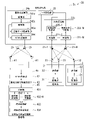
- FIG. 1 is a diagram showing a configuration example of the wireless communication system 1 according to the first embodiment.
- the wireless communication system 1 has a mobile relay station 2, a terminal station 3, and a base station 4.
- the number of each of the mobile relay station 2, the terminal station 3, and the base station 4 included in the wireless communication system 1 is arbitrary, but it is assumed that the number of the terminal stations 3 is large.
- the mobile relay station 2 is mounted on the mobile body.
- the mobile relay station 2 is an example of a relay device in which a communicable area moves with the passage of time.
- the mobile relay station 2 is provided in, for example, a LEO (Low Earth Orbit) satellite.
- the altitude of the LEO satellite is 2000 km or less, and the LEO satellite orbits the earth in about 1.5 hours per orbit.
- the terminal station 3 and the base station 4 are installed on the earth such as on the ground or at sea.
- the terminal station 3 is, for example, an IoT terminal.
- the terminal station 3 collects data such as environmental information (for example, temperature) detected by the sensor and wirelessly transmits it to the mobile relay station 2.
- FIG. 1 shows two terminal stations 3 as an example among a large number of terminal stations 3.
- the mobile relay station 2 receives data transmitted from each of the plurality of terminal stations 3 by wireless signals while moving over the terminal station 3.
- the mobile relay station 2 wirelessly transmits these received data to the base station 4.
- the base station 4 receives the data collected from the terminal station 3 by the mobile relay station 2 from the mobile relay station 2.
- a mobile relay station it is conceivable to use a geostationary satellite or a relay station (relay device) mounted on an unmanned aerial vehicle such as a drone or HAPS (High Altitude Platform Station).
- a relay station mounted on a geostationary satellite although the coverage area (footprint) on the ground is wide, the link budget for the IoT terminal installed on the ground is very small due to the high altitude.
- the link budget is high, but the coverage area is narrow.
- drones require batteries and HAPS require solar panels.
- the mobile relay station 2 is mounted on the LEO satellite. Therefore, the link budget is within a predetermined limit. Further, since the LEO satellite orbits outside the atmosphere, the air resistance of the LEO satellite is low and the fuel consumption of the LEO satellite is also low. In addition, the footprint of LEO satellites is larger than when relay stations are mounted on drones and HAPS.
- the mobile relay station 2 mounted on the LEO satellite communicates while moving at high speed, a Doppler shift occurs in the radio signal.
- the link budget of the relay station (relay device) mounted on the LEO satellite is smaller than that in the case where the relay station is mounted on the drone or HAPS. Therefore, the mobile relay station 2 receives a radio signal from the terminal station 3 through a plurality of antennas, and transmits the radio signal to the base station 4 by the plurality of antennas. Communication quality can be improved by the diversity effect of communication using multiple antennas and the beamforming effect.
- the mobile relay station 2 relays the radio signal received from the terminal station 3 using a plurality of antennas to the base station 4 using MIMO (Multiple Input Multiple Output).
- MIMO Multiple Input Multiple Output
- the mobile relay station 2 includes N antennas 21 (N is an integer of 2 or more), a terminal communication unit 22, a base station communication unit 24, and a plurality of antennas 25.
- the N antennas 21 are referred to as antennas 21-1 to 21-N.
- the terminal communication unit 22 has N reception units 221 and a terminal signal reception processing unit 222.
- the N receiving units 221 are referred to as receiving units 221-1 to 221-N.
- the receiving unit 221-n (n is an integer of 1 or more and N or less) receives the terminal uplink signal by the antenna 21-n.
- the terminal signal reception processing unit 222 performs reception processing of the terminal uplink signal.
- the terminal signal reception processing unit 222 has N frequency conversion units 223 and a signal processing unit 224.
- the N frequency conversion units 223 are referred to as frequency conversion units 223-1 to 223-N.
- the frequency conversion unit 223-n (n is an integer of 1 or more and N or less) converts the 920 MHz band RF (Radio Frequency) signal received by the reception unit 221-n into a baseband signal using an orthogonal demodulator or the like.
- the frequency conversion unit 223-n outputs the baseband signal to the signal processing unit 224.
- the signal processing unit 224 synthesizes the baseband signals (symbols) input from each of the frequency conversion units 223-1 to 223-N. For example, the signal processing unit 224 adds and synthesizes the baseband signals of each receiving system. Further, for example, the signal processing unit 224 multiplies the baseband signal of each receiving system by a weight for performing amplitude correction and phase correction so that the baseband signals of each receiving system are strengthened and synthesized. May be good. Combining the baseband signals of each receiving system by performing amplitude correction and phase correction corresponds to reception beam control.
- the signal processing unit 224 is equipped with an analog-to-digital converter.
- the frequency used by the 920 MHz band LPWA (Low Power Wide Area) in Japan is in the range of 915 MHz to 928 MHz (13 MHz width).
- the analog-to-digital converter of the signal processing unit 224 executes sampling at a sampling rate of 26 MHz or higher, which is twice the frequency used by the 920 MHz band LPWA (sampling theorem), for example.
- the signal processing unit 224 converts the baseband signal (analog signal) into a baseband signal (digital signal).
- the signal processing unit 224 executes frame detection and Doppler shift compensation for the baseband signal (digital signal).
- This frame detection is to detect a terminal uplink signal (frame) from among the radio signals constantly received by the plurality of antennas 21.
- the signal processing unit 224 synthesizes the results of frame detection and Doppler shift compensation.
- the signal processing unit 224 outputs the obtained symbol (synthesis result) to the base station communication unit 24.
- the signal processing unit 224 may execute the received beam control by analog processing.
- the signal processing unit 224 synthesizes the baseband signals input from each of the frequency conversion units 223-1 to 223-N by analog processing.
- the signal processing unit 224 outputs the synthesized baseband signal (analog signal) to the base station communication unit 24.
- the base station communication unit 24 is a functional unit that relays the terminal uplink signal to the base station 4 by MIMO.
- the base station communication unit 24 includes a storage unit 241, a control unit 242, a transmission data modulation unit 243, and a MIMO transmission unit 244.
- the storage unit 241 stores in advance the weights of the base station downlink signals transmitted from each antenna 25 for each transmission time.
- the transmission time may be expressed as, for example, the elapsed time from the transmission start timing.
- the weight for each transmission time is derived based on the orbit information of the LEO satellite and the position of each antenna station 41.
- the orbit information of LEO is information that can obtain the position, speed, moving direction, etc. of the LEO satellite at an arbitrary time.
- the wait for each transmission time of the base station downlink signal may be constant regardless of the transmission time.
- the control unit 242 instructs the MIMO transmission unit 244 of the wait for each transmission time read from the storage unit 241.
- the transmission data modulation unit 243 acquires the baseband signal output from the signal processing unit 224 as transmission data.
- the transmission data modulation unit 243 converts the acquired transmission data into a parallel signal and executes a modulation process on the parallel signal.
- the MIMO transmission unit 244 generates a base station downlink signal transmitted from each antenna 25 by performing weighting on the parallel signal using the weight instructed by the control unit 242.
- the MIMO transmission unit 244 transmits the generated base station downlink signal from the antenna 25 by, for example, MIMO.
- the terminal station 3 includes a data storage unit 31, a transmission unit 32, and one or more antennas 33.
- the data storage unit 31 stores sensor data and the like.
- the transmission unit 32 reads the sensor data as terminal transmission data from the data storage unit 31.
- the transmission unit 32 transmits a terminal uplink signal (wireless signal) including the read terminal transmission data from the antenna 33.
- the transmission unit 32 transmits a radio signal using, for example, LPWA.
- LPWA includes wireless communication methods such as LoRaWAN (registered trademark), Sigfox (registered trademark), LTE-M (LongTermEvolution for Machines), and NB (NarrowBand) -IoT, but any wireless communication method is used. be able to.
- the transmission unit 32 may execute communication with another terminal station 3 by time division multiplexing, OFDM (Orthogonal Frequency Division Multiplexing), MIMO, or the like.
- the transmission unit 32 determines the channel and transmission timing used by the station to transmit the terminal uplink signal by a method predetermined in the wireless communication method to be used. Further, the transmitting unit may form a beam of a radio signal transmitted from a plurality of antennas 33 according to a predetermined method in the wireless communication method to be used.
- the base station 4 includes a plurality of antenna stations 41, a MIMO receiving unit 42, a base station signal receiving processing unit 43, and a terminal signal receiving processing unit 44.
- the antenna station 41 is arranged at a position away from the other antenna stations 41 so that the difference in the arrival angles of the radio signals transmitted from each of the plurality of antennas 25 of the mobile relay station 2 becomes large.
- Each antenna station 41 converts the base station downlink signal received from the mobile relay station 2 into an electric signal, and outputs the converted electric signal to the MIMO receiving unit 42.
- the MIMO receiving unit 42 aggregates the base station downlink signals received from the plurality of antenna stations 41.
- the MIMO receiving unit 42 stores the weight for each reception time for the base station downlink signal received by each antenna station 41 based on the orbit information of the LEO satellite and the position of each antenna station 41. This reception time may be expressed as an elapsed time from the timing of the start of reception.
- the MIMO receiving unit 42 multiplies the base station downlink signal input from each antenna station 41 by a weight corresponding to the reception time of the base station downlink signal. Further, the MIMO receiving unit 42 synthesizes the received signal multiplied by the weight. The same weight may be used regardless of the reception time.
- the base station signal reception processing unit 43 converts the synthesized reception signal (RF signal) into a baseband signal.
- the base station signal reception processing unit 43 outputs the baseband signal to the terminal signal reception processing unit 44.
- the terminal signal reception processing unit 44 performs decoding processing of the terminal uplink signal.
- the terminal signal reception processing unit 44 decodes the symbol of the terminal uplink signal indicated by the baseband signal, and obtains the terminal transmission data transmitted from the terminal station 3.
- a low earth orbit satellite (mobile body) equipped with a mobile relay station 2 passes over a predetermined position a predetermined number of times per day along a predetermined orbit.
- the degree of influence (degree of interference) of unnecessary waves on the reception sensitivity of the terminal uplink signal differs depending on the position of the mobile relay station 2.
- the mobile relay station 2 moves on the path connecting the base station and the geostationary satellite. It grows as it passes.
- the mobile relay station 2 orbiting the earth measures the signal level (received power) information of the radio signal in advance as radio wave environment information.
- the mobile relay station 2 stores in advance history information including the position information of the mobile relay station 2 in which the signal level of the radio signal is equal to or higher than the threshold value.
- the mobile relay station 2 determines whether or not the position where the signal level of the unnecessary wave is equal to or higher than the threshold value in the history information is the same as the current position of the mobile relay station 2.
- the mobile relay station 2 is a signal processing system related to the received radio signal depending on whether or not the position where the signal level of the unnecessary wave is equal to or higher than the threshold value in the history information is the same as the current position of the mobile relay station 2.
- This threshold value is, for example, the value of the input level “P 1 dB” at which the amplifier provided in the mobile relay station 2 starts operating in the non-linear region.
- the threshold value may be a value having a margin of about several dB with respect to the input level “P 1 dB”.
- the mobile relay station 2 receives a radio signal received by, for example, a system in which the bandpass filter is in front of the low noise amplifier before or during passing through a position (for example, above an urban area) where the influence of unnecessary waves is large. Switch the signal processing system related to (RF signal). After passing through a position where the influence of unnecessary waves is large, the mobile relay station 2 switches the signal processing system related to the received radio signal to, for example, the system in which the low noise amplifier is in front of the bandpass filter.
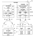
- FIG. 2 is a diagram showing a configuration example of the receiving unit 221 in the first embodiment.
- the receiving unit 221 includes an antenna 21, a switching control unit 301, a measuring unit 302, a position detecting unit 303, a storage unit 304, a first output unit 305, and a second output unit 306.
- the measuring unit 302, the position detecting unit 303, and the storage unit 304 may be provided in at least one of the receiving units 221-1 to 221-N.
- the switching control unit 301 of each reception unit 221 may share the measurement result of the signal level in any reception unit 221.
- the switching control unit 301 includes, for example, an RF switch (Radio Frequency switch).
- the first output unit 305 includes an amplifier 307-1 and a filter 308-1.
- the output terminal of the switching control unit 301 and the input terminal of the amplifier 307-1 are connected.
- the output terminal of the amplifier 307-1 and the input terminal of the filter 308-1 are connected.
- the output terminal of the filter 308-1 and the input terminal of the frequency conversion unit 223 are connected.
- the second output unit 306 includes an amplifier 307-2 and a filter 308-2.
- the output terminal of the switching control unit 301 and the input terminal of the filter 308-2 are connected.
- the output terminal of the filter 308-2 and the input terminal of the amplifier 307-2 are connected.
- the output terminal of the amplifier 307-2 and the input terminal of the frequency conversion unit 223 are connected.
- Each antenna 21 receives a terminal uplink signal in a desired frequency band from one or more terminal stations 3.
- the desired frequency band is a frequency band associated with the terminal station 3, for example, a 920 MHz band. Since the propagation distance of the terminal uplink signal is long, the signal level (received power) of the terminal uplink signal is weak. Further, each antenna 21 receives a radio signal in a predetermined band including a desired frequency band. In this received radio signal, a radio signal (unnecessary wave) other than the desired frequency band may interfere with a weak terminal uplink signal (desired wave) in the desired frequency band.
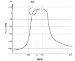
- FIG. 3 is a diagram showing an example of the frequency characteristic of the antenna gain of the receiving antenna in the first embodiment.
- the horizontal axis indicates the frequency.
- the vertical axis shows the antenna gain of the antenna 21.
- the unnecessary wave 400 in the band from about 900 MHz to about 915 MHz used in a cellular system such as LTE (Long Term Evolution) and the radio signal (desired wave) in the desired frequency band have the same antenna gain. Will be received at. Therefore, when the unwanted wave 400 arrives at the mobile relay station 2 at the same time and is synthesized, the unwanted wave 400 is received by the antenna 21 at a signal level much higher than the radio signal in the desired frequency band. In this case, it is necessary to suppress the signal level of the unnecessary wave 400 by using a bandpass filter that passes a signal in a desired frequency band.
- the switching control unit 301 is a functional unit that switches the output destination of the radio signal received by the plurality of antennas 21 to either the first output unit 305 or the second output unit 306 in the subsequent stage.
- the switching control unit 301 refers to the history information stored in the storage unit 304 regarding the satellite position “p (t)” at the time “t” in the orbit around the earth.
- the history information includes information on the signal level of unnecessary waves in the past (for example, at the time of the previous orbit), satellite position information, and reception time information.
- the radio signal (unnecessary wave) other than the desired frequency band does not interfere (the signal level of the unnecessary wave is a constant value). If it is less than), an analog signal corresponding to the received radio signal is input to the first output unit 305. That is, in the switching control unit 301, the position of the mobile relay station 2 at present and the position of the mobile relay station 2 in the past are the same, and the signal level of the analog signal corresponding to the radio signal at that position in the history information is a threshold value. If it is less than, the analog signal is input to the first output unit 305.
- the switching control unit 301 When the switching control unit 301 interferes with the weak terminal uplink signal in the desired frequency band in the history information by a wireless signal (unnecessary wave) other than the desired frequency band, the switching control unit 301 changes to the received wireless signal.
- the corresponding analog signal is input to the second output unit 306. That is, in the switching control unit 301, the position of the mobile relay station 2 at present and the position of the mobile relay station 2 in the past are the same, and the signal level of the analog signal corresponding to the radio signal at that position in the history information is a threshold value. In the above case, the analog signal is input to the second output unit 306.
- the measurement unit 302 is a functional unit that measures the signal level of the analog signal corresponding to the radio signal in each antenna 21 or the switching control unit 301, and is, for example, a spectrum analysis device or a power meter.
- the measuring unit 302 acquires the analog signal generated by the switching control unit 301 from the switching control unit 301.
- the measuring unit 302 measures the signal level of the analog signal corresponding to the received radio signal in a predetermined band in which the antenna 21 has a gain.
- the measurement unit 302 may stop the measurement process during a period predetermined as a period during which the measurement of unnecessary waves is unnecessary.
- the position detection unit 303 detects the position of the mobile relay station 2 at a predetermined cycle based on the orbit information of the mobile relay station 2.
- the position detection unit 303 records the position information of the mobile relay station 2 in the storage unit 304.
- the storage unit 304 stores in advance the signal level of the analog signal corresponding to the radio signal in the predetermined band as history information in association with the position of the mobile relay station 2.
- an analog signal corresponding to a radio signal with less interference due to unnecessary waves is input to the amplifier 307-1 from the switching control unit 301.
- the amplifier 307-1 amplifies the amplitude of the input analog signal.
- the amplifier 307-1 outputs an analog signal with amplified amplitude to the filter 308-1.
- the filter 308-1 is a bandpass filter that allows signals in a desired frequency band to pass through.
- the filter 308-1 extracts an analog signal in a desired frequency band from the analog signal whose amplitude is amplified by the amplifier 307-1. This makes it possible to suppress the signal level of unnecessary waves other than the desired frequency band.
- the filter 308-1 outputs the extracted analog signal to the frequency conversion unit 223.
- an amplifier 307-1 to which an analog signal with less interference is input is provided in front of the filter 308-1. Therefore, even if there is an insertion loss of the filter 308-1, the noise figure (Noise Figure: NF) of the amplifier 307-1 is unlikely to increase.
- an analog signal corresponding to a radio signal having a large amount of interference due to unnecessary waves is input to the filter 308-2 from the switching control unit 301.
- the filter 308-2 is a bandpass filter that passes a signal in a desired frequency band.
- the filter 308-2 extracts an analog signal in a desired frequency band from the input analog signals. This makes it possible to suppress the signal level of unnecessary waves other than the desired frequency band.
- the filter 308-2 outputs the extracted analog signal to the amplifier 307-2.
- Amplifier 307-2 amplifies the amplitude of the extracted analog signal.
- the noise figure of the entire receiving unit 221 when the analog signal is input to the second output unit 306 is the case where the analog signal is input to the first output unit 305 due to the insertion loss of the filter 308-2 in the previous stage. It is larger than the noise figure of the entire receiving unit 221 of the above.
- the second output unit 306 since the signal level of the unwanted wave is suppressed by the filter 308-2 in the previous stage, it is possible to prevent the unwanted wave signal component from leaking into the desired frequency band due to the nonlinear amplification of the unwanted wave. It is possible to prevent a decrease in reception sensitivity.
- the amplifier 307-2 outputs the analog signal whose amplitude is amplified to the frequency conversion unit 223.
- a high-power interference signal (of the unwanted wave) in a frequency band adjacent to the frequency band of the desired signal (hereinafter referred to as “adjacent frequency band”).
- adjacent frequency band a frequency band adjacent to the frequency band of the desired signal
- the interference signal is amplified in the non-linear region of the input / output characteristics of the amplifier 307-1, so that the interference signal is distorted.
- the interference signal is distorted (the spectrum of the interference signal is disturbed), the amount of leakage of the signal component to the outside of the band of the interference signal increases.
- the high power interference signal of the adjacent frequency band is input to the amplifier 307-1 in the first output unit 305, the amount of the interference signal of the adjacent frequency band leaking into the frequency band of the desired signal increases. It will be.
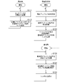
- FIG. 4 is a flowchart showing the processing of the wireless communication system 1.
- the terminal station 3 acquires data detected by a sensor (not shown) provided in the terminal station 3 at any time, and writes the acquired data in the data storage unit 31 (step S111).
- the transmission unit 32 reads the sensor data as terminal transmission data from the data storage unit 31.
- the transmission unit 32 wirelessly transmits a terminal uplink signal including terminal transmission data from the antenna 33 at a transmission start timing derived in advance based on the orbit information of the LEO satellite equipped with the mobile relay station 2 (step S112).
- the terminal station 3 repeats the process from step S111.
- the receiving units 221-1 to 221-N of the mobile relay station 2 receive the terminal uplink signal transmitted from the terminal station 3 (step S121).
- the terminal uplink signal is received from only one terminal station 3 on a time-division basis for the same frequency, and cases where the terminal uplink signal is received from multiple terminal stations 3 at the same frequency at the same frequency. It may receive a terminal uplink signal.
- the terminal signal reception processing unit 222 executes signal processing on the terminal uplink signal received in step S121 (step S122). Specifically, the frequency conversion unit 223-n specifies the wireless communication system based on the information unique to the wireless communication system included in the terminal uplink signal received by the receiving unit 221-n.
- the receiving units 221-1 to 221-N output the baseband signal corresponding to the terminal uplink signal to the signal processing unit 224 according to the specified wireless communication method.
- the signal processing unit 224 outputs the synthesis information, which is the result of the synthesis of the baseband signals input from each of the frequency conversion units 223-1 to 223-N, to the transmission data modulation unit 243.
- the signal transmitted from the terminal station 3 Since the signal transmitted from the terminal station 3 has a correlation, the signal is emphasized by synthesizing the baseband signal. Also, by synthesizing the baseband signal, the influence of noise randomly added to the signal is reduced. Therefore, the diversity effect can be obtained for the terminal uplink signal received by the mobile relay station 2 from only one terminal station 3 at the same time. Further, for the terminal uplink signals received by the mobile relay station 2 from a plurality of terminal stations 3 at the same time, the synthesis of the baseband signal corresponds to performing MIMO communication.
- the transmission data modulation unit 243 acquires the composite information as transmission data from the signal processing unit 224.
- the transmission data modulation unit 243 modulates the transmission data after parallel conversion.
- the MIMO transmission unit 244 executes weighting on the transmission data modulated by the transmission data modulation unit 243 using the weight instructed by the control unit 242. As a result, the MIMO transmitter 244 generates a base station downlink signal transmitted from each antenna 25.
- the MIMO transmission unit 244 transmits each generated base station downlink signal from the antenna 25 by MIMO (step S123).
- the mobile relay station 2 repeats the process from step S121.
- Each antenna station 41 of the base station 4 receives the base station downlink signal from the mobile relay station 2 (step S131).
- Each antenna station 41 converts the received base station downlink signal into an electric signal, and outputs the converted electric signal as a reception signal to the MIMO receiving unit 42.
- the MIMO receiving unit 42 synchronizes the timing of the received signal received from each antenna station 41.
- the MIMO receiving unit 42 multiplies the received signal received by each antenna station 41 by the weight, and adds the multiplication result.
- the base station signal reception processing unit 43 acquires the synthesized information from the received signal (step S132).
- the base station signal reception processing unit 43 outputs the synthesized information to the terminal signal reception processing unit 44.
- the terminal signal decoding unit 441 of the terminal signal reception processing unit 44 decodes the symbol of the terminal uplink signal indicated by the synthetic information and obtains the terminal transmission data transmitted from the terminal station 3 (step S133).
- the terminal signal decoding unit 441 can also use a decoding method having a large calculation load, such as SIC (Successive Interference Cancellation).
- SIC Successessive Interference Cancellation
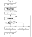
- FIG. 5 is a flowchart showing an operation example of the receiving unit 221 in the first embodiment.
- the measuring unit 302 measures the signal level of the radio signal in advance in a predetermined band in which the antenna 21 has a gain.
- the position detection unit 303 detects the position of the mobile relay station 2 based on the orbit information of the mobile relay station 2 (step S101).
- the storage unit 304 stores in advance the signal level and reception time of the analog signal corresponding to the radio signal in the predetermined band as history information in association with the position of the mobile relay station 2 (step S102).
- the switching control unit 301 stores the storage unit 304. Further refer to the stored history information.
- the switching control unit 301 acquires the signal level information at that position from the history information. It should be noted that it may be determined whether or not the reception time and the current time in the history information belong to the same time zone. When it is determined that they belong to the same time zone, the switching control unit 301 may acquire the signal level information from the history information (step S104). The switching control unit 301 determines whether or not the signal level associated with the position in the history information is equal to or higher than the threshold value (step S105).
- the mobile relay station receives the terminal uplink signal of the terminal station by diversity reception, MIMO reception, or the like. Therefore, the link budget with the terminal station can be improved.
- the mobile relay station transmits the terminal uplink signal to the base station in MIMO. Therefore, the mobile relay station can collectively transmit the terminal uplink signals received from a large number of terminal stations to the base station with a large capacity and high quality.
- the mobile relay station 2 moves, for example, along an orbit around the earth.
- Each antenna 21 receives a first radio signal in a predetermined band including a desired frequency band (for example, 920 MHz) associated with the terminal station 3 (first communication device).
- a desired frequency band for example, 920 MHz
- the measuring unit 302 measures the signal level of the analog signal corresponding to the received first radio signal in a predetermined band in which the antenna 21 has a gain.
- the position detection unit 303 detects the position of the mobile relay station 2 (relay device).
- the storage unit 304 stores the signal level of the analog signal corresponding to the first radio signal in the predetermined band as history information in association with the position of the mobile relay station 2.
- the switching control unit 301 stores the storage unit 304. Further refer to the stored history information.
- the switching control unit 301 receives the first radio.
- An analog signal corresponding to the signal is input to the first output unit 305.
- the switching control unit 301 has the same position of the mobile relay station 2 (relay device) at present and the position of the mobile relay station 2 in the history information (position of the mobile relay station 2 in the past), and is in the history information.
- the analog signal corresponding to the received first radio signal is input to the first output unit 305.
- the switching control unit 301 When the signal level of the analog signal other than the desired frequency band in the predetermined band is equal to or higher than the threshold value (when there is a lot of interference with the desired wave), the switching control unit 301 inputs the analog signal corresponding to the received first radio signal. , Is input to the second output unit 306. For example, in the switching control unit 301, the current position of the mobile relay station 2 and the position of the mobile relay station 2 in the history information are the same, and the signal level associated with the position in the history information is equal to or higher than the threshold value. In this case, an analog signal corresponding to the received first radio signal is input to the second output unit 306.
- the amplifier 307-1 When an analog signal corresponding to the received first radio signal is input to the first output unit 305, the amplifier 307-1 amplifies the amplitude of the input analog signal.
- the filter 308-1 (bandpass filter) extracts an analog signal in a desired frequency band from the analog signal whose amplitude is amplified.
- the filter 308-1 outputs the extracted analog signal to the frequency conversion unit 223.
- the filter 308-2 (bandpass filter) is an analog signal in a desired frequency band from the input analog signals.
- Amplifier 307-2 amplifies the amplitude of the extracted analog signal.
- the amplifier 307-2 outputs the analog signal whose amplitude is amplified to the frequency conversion unit 223.
- the MIMO transmission unit 244 (transmission unit) is connected to the second radio signal (base station downlink signal) corresponding to the analog signal output from the first output unit 305 to the frequency conversion unit 223, or to the frequency conversion unit 223.
- a third radio signal (base station downlink signal) corresponding to the analog signal output from the second output unit 306 may be transmitted to the base station 4 (second communication device).
- the mobile relay station In the first modification of the first embodiment, the mobile relay station accumulates the synthetic information of the baseband signal, and wirelessly transmits the base station downlink signal including the accumulated synthetic information to the base station 4.
- the first modification of the first embodiment will be described focusing on the difference from the first embodiment.
- FIG. 6 is a diagram showing a configuration example of the wireless communication system 1a in the first modification of the first embodiment.
- the mobile relay station 2a includes N antennas 21, a terminal communication unit 22, a data storage unit 23, a base station communication unit 24, and a plurality of antennas 25.
- the data storage unit 23 stores the combined information of the baseband signal synthesized by the signal processing unit 224.
- the data storage unit 23 outputs the composite information to the transmission data modulation unit 243.
- the mobile relay station 2 wirelessly transmits the base station downlink signal including the decoding result of the synthetic information to the base station 4.
- the second modification of the first embodiment will be described focusing on the difference from the first embodiment.
- FIG. 7 is a diagram showing a configuration example of the wireless communication system 1b in the second modification of the first embodiment.
- the terminal signal reception processing unit 222 includes N frequency conversion units 223, a signal processing unit 224, and a terminal signal decoding unit 226.
- the frequency conversion unit 223 converts the terminal uplink signal received by the reception unit 221-n into a baseband signal, and outputs the baseband signal to the signal processing unit 224.
- the signal processing unit 224 synthesizes the baseband signals input from each of the frequency conversion units 223-1 to 223-N.
- the terminal signal decoding unit 226 executes a decoding process on the composite information (symbol) that is the result of the synthesis of the baseband signal.
- the terminal signal decoding unit 226 outputs the decoding result to the transmission data modulation unit 243.
- the base station 4b includes a plurality of antenna stations 41, a MIMO receiving unit 42, and a base station signal receiving processing unit 43.
- the base station signal reception processing unit 43 acquires the received decoding result from the MIMO receiving unit 42.
- the mobile relay station In the third modification of the first embodiment, the mobile relay station accumulates the waveform data of the terminal uplink signal and wirelessly transmits the base station downlink signal including the accumulated waveform data to the base station 4.
- the first modification of the first embodiment will be described focusing on the difference from the first embodiment.
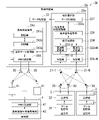
- FIG. 8 is a diagram showing a configuration example of the wireless communication system 1c according to the first modification of the first embodiment.
- the wireless communication system 1c has a mobile relay station 2c, a terminal station 3, and a base station 4a.
- the mobile relay station 2c mounted on the LEO satellite communicates while moving at high speed. Specifically, when the mobile relay station 2c is viewed from the ground, the mobile relay station 2c passes over the sky in about a few minutes. Therefore, the time during which each terminal station 3 or base station 4c can communicate with the mobile relay station 2c with high quality is limited, and the time may differ between the terminal station 3 and the base station 4c.
- the terminal station 3 uses wireless communication methods having various specifications.
- the mobile relay station 2c of the first modification of the first embodiment receives the terminal uplink signal from the terminal station 3 within the coverage at the current position during movement, and the waveform data of the received terminal uplink signal.
- the mobile relay station 2c wirelessly transmits a base station downlink signal including waveform data of the terminal uplink signal to the base station 4c at the timing when the base station 4c exists in the coverage.
- the base station 4c obtains waveform data of the terminal uplink signal by executing frequency conversion processing on the base station downlink signal received from the mobile relay station 2c.
- the base station 4c obtains terminal transmission data which is the data transmitted by the terminal station 3 by decoding the waveform data.
- the mobile relay station 2c includes N antennas 21 (N is an integer of 2 or more), a terminal communication unit 22c, a data storage unit 23, a base station communication unit 24c, and a plurality of antennas 25.
- the terminal communication unit 22c has N reception units 221 and N reception waveform recording units 225.
- the N received waveform recording units 225 are referred to as received waveform recording units 225-1 to 225-N.
- the received waveform recording unit 225-n (n is an integer of 1 or more and N or less) samples the received waveform of the terminal uplink signal received by the receiving unit 221-n, and generates waveform data showing the value obtained by sampling. do.
- the received waveform recording unit 225-n stores the received waveform information including the antenna identifier of the antenna 21-n, the reception time of the terminal uplink signal at the antenna 21-n, and the generated waveform data in the data storage unit 23. Record.
- the antenna identifier is information that identifies the antenna 21-n.
- the data storage unit 23 stores received waveform information including waveform data of the terminal uplink signal received by each of the antennas 21-1 to 21-N.
- the base station communication unit 24c includes a storage unit 241c, a control unit 242c, a transmission data modulation unit 243c, and a MIMO transmission unit 244.
- the storage unit 241c stores the transmission start timing calculated in advance based on the orbit information of the LEO satellite equipped with the mobile relay station 2c and the position of the base station 4. Further, the storage unit 241c stores in advance the weights of the base station downlink signals transmitted from each antenna 25 for each transmission time. A certain weight may be used regardless of the transmission time.
- the control unit 242c controls the transmission data modulation unit 243c and the MIMO transmission unit 244 so that the received waveform information is transmitted to the base station 4c at the transmission start timing stored in the storage unit 241c. Further, the control unit 242c instructs the MIMO transmission unit 244 of the wait for each transmission time read from the storage unit 241c.
- the transmission data modulation unit 243c reads the received waveform information as transmission data from the data storage unit 23.
- the transmission data modulation unit 243c converts the read transmission data into a parallel signal and modulates the parallel signal.
- the transmission data modulation unit 243c outputs the modulated parallel signal to the MIMO transmission unit 244.
- the MIMO transmission unit 244 generates a base station downlink signal transmitted from each antenna 25 by performing weighting on the parallel signal using the weight instructed by the control unit 242.
- the MIMO transmission unit 244 transmits the generated base station downlink signal from the antenna 25 by MIMO.
- the base station 4c includes a plurality of antenna stations 41, a MIMO receiving unit 42, a base station signal receiving processing unit 43, and a terminal signal receiving processing unit 45.
- the terminal signal reception processing unit 45 includes a distribution unit 451, a plurality of frequency conversion units 452, a signal processing unit 453, and a terminal signal decoding unit 454.
- the terminal signal reception processing unit 45 acquires the reception waveform information received by the base station signal reception processing unit 43.
- the terminal signal reception processing unit 45 performs reception processing of the terminal uplink signal indicated by the received waveform information.
- the terminal signal reception processing unit 45 performs reception processing using the wireless communication method used for transmission by the terminal station 3 to acquire terminal transmission data.
- the terminal signal reception processing unit 45 includes a distribution unit 451, N frequency conversion units 452, a signal processing unit 453, and a terminal signal decoding unit 454.
- the N frequency conversion units 452 are referred to as frequency conversion units 452-1 to 452-N.
- the distribution unit 451 reads out the waveform data at the same reception time from the received waveform information, and the read waveform data is sent to the frequency conversion units 452-1 to 452-N according to the antenna identifier associated with the waveform data. Output. That is, the distribution unit 451 outputs the waveform data associated with the antenna identifier of the antenna 21-n to the frequency conversion unit 452-n.
- Each of the frequency conversion units 452-1 to 452-N executes frequency conversion processing on the waveform data, and outputs the symbol obtained by the frequency conversion processing to the signal processing unit 453.
- the frequency conversion unit 452-n performs a process of compensating for the Doppler shift of the terminal uplink signal received by the antenna 21-n of the mobile relay station 2 with respect to the signal indicated by the waveform data, and then performs a frequency conversion process. You may.
- the Doppler shift received by the terminal uplink signal received by each antenna 21-n is calculated in advance based on the position of the terminal station 3 and the orbit information of the LEO on which the mobile relay station 2a is mounted.
- the signal processing unit 453 synthesizes the symbols input from each of the frequency conversion units 452-1 to 452-N, and outputs the combined symbols to the terminal signal decoding unit 454.
- the terminal signal decoding unit 454 decodes the synthesized symbol and obtains the terminal transmission data transmitted from the terminal station 3.
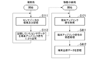
- FIG. 9 is a flowchart showing the processing of the wireless communication system 1a when the uplink signal is transmitted from the terminal station 3.
- the terminal station 3 performs the same processing as the processing of steps S111 to S112 in the processing flow of the first embodiment shown in FIG.
- the receiving units 221-1 to 221-N of the mobile relay station 2c receive the terminal uplink signal transmitted from the terminal station 3 (step S121).
- the received waveform recording unit 225-n provides waveform data representing the waveform of the terminal uplink signal received by the receiving unit 221-n, and received waveform information in which the reception time and the antenna identifier of the antenna 21-n are associated with each other.
- the mobile relay station 2c repeats the process from step S121.
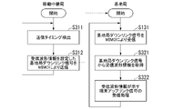
- FIG. 10 is a flowchart showing the processing of the wireless communication system 1c when the base station downlink signal is transmitted from the mobile relay station 2c.
- the same processes as those shown in the flowchart of the first embodiment shown in FIG. 4 are designated by the same reference numerals.
- Step S311 When the control unit 242c of the base station communication unit 24a of the mobile relay station 2c detects that it is the transmission start timing stored in the storage unit 241c, it transmits the received waveform information to the transmission data modulation unit 243c and the MIMO transmission unit 244.
- the transmission data modulation unit 243c reads out the received waveform information stored in the data storage unit 23 as transmission data.
- the transmission data modulation unit 243c converts the read transmission data into a parallel signal and modulates the parallel signal.
- the MIMO transmission unit 244 executes weighting on the transmission data modulated by the transmission data modulation unit 243c by the weight instructed by the control unit 242c. As a result, the MIMO transmitter 244 generates a base station downlink signal transmitted from each antenna 25.
- the MIMO transmission unit 244 transmits each generated base station downlink signal from the antenna 25 by MIMO (step S312).
- the mobile relay station 2 repeats the process from step S311.
- the base station 4c receives the base station downlink signal from the mobile relay station 2c by MIMO, as in the first embodiment shown in FIG. 4 (step S131). Specifically, each antenna station 41 converts the base station downlink signal received from the mobile relay station 2c into an electric signal, and outputs the converted electric signal as a reception signal to the MIMO receiving unit 42.
- the MIMO receiving unit 42 synchronizes the timing of the received signal received from each antenna station 41.
- the MIMO receiving unit 42 multiplies the received signal received by each antenna station 41 by the weight, and adds the received signal to which the weight is multiplied.
- the base station signal reception processing unit 43 receives the added reception signal (step S321).
- the base station signal reception processing unit 43 outputs the reception waveform information obtained from the reception signal to the terminal signal reception processing unit 45.
- the terminal signal reception processing unit 45 performs reception processing of the terminal uplink signal indicated by the received waveform information (step S322). Specifically, the distribution unit 451 reads waveform data having the same reception time from the received waveform information, and reads the read waveform data according to the antenna identifier associated with the waveform data, frequency conversion unit 452-1. Output to ⁇ 452-N.
- the frequency conversion units 452-1 to 452-N specify the wireless communication method used by the terminal station 3 to transmit the terminal uplink signal based on the information unique to the wireless communication method included in the received signal represented by the waveform data. ..
- the frequency conversion units 452-1 to 452-N execute frequency conversion processing on the received signal represented by the waveform data according to the specified wireless communication method, and output the obtained symbol to the signal processing unit 453.
- the signal processing unit 453 executes frame detection, Doppler shift compensation, and offline beam control for the synthesized baseband signal.
- This offline beam control is a received beam control in which the mobile relay station transmits the recorded waveform data to the base station and the base station executes it as post-processing, instead of the mobile relay station performing the received beam control. ..
- the signal processing unit 453 synthesizes the baseband signals (symbols) input from each of the frequency conversion units 452-1 to 452-N. Since the signal transmitted by the terminal station 3 has a correlation, the signal is emphasized by synthesis. In addition, the effect of noise randomly added to the signal is reduced by synthesis. Therefore, the diversity effect can be obtained for the terminal uplink signal received by the mobile relay station 2c from only one terminal station 3 at the same time. Further, for the terminal uplink signals received by the mobile relay station 2c from a plurality of terminal stations 3 at the same time, the synthesis corresponds to performing MIMO communication. The signal processing unit 453 outputs the synthesized symbol to the terminal signal decoding unit 454.
- the terminal signal decoding unit 454 decodes the baseband signal (symbol) synthesized by the signal processing unit 453 by the specified wireless communication method. As a result, the terminal signal decoding unit 454 obtains the terminal transmission data transmitted from the terminal station 3.
- the terminal signal decoding unit 454 can also use a decoding method having a large calculation load, such as SIC.
- the base station 4c repeats the process from step S131.
- the mobile relay station receives the terminal uplink signal received from the terminal station by diversity reception, MIMO reception, or the like, as in the first embodiment. Therefore, the link budget with the terminal station can be improved. Further, the mobile relay station transmits the information of the received waveform of the terminal uplink signal to the base station by MIMO. Therefore, while the base station is included in the communicable area of the mobile relay station, it is possible to collectively transmit the received waveforms of the terminal uplinks received from a large number of terminal stations in a large capacity and with good quality. can.
- the mobile relay station 2c does not include the frequency conversion unit 223.
- the mobile relay station 2c saves and stores information on the received signal waveform without executing frequency conversion processing on the terminal uplink signal (RF signal) received from the terminal station 3, and at a timing at which communication is possible. MIMO transmission to base station 4.
- the base station 4c performs reception processing such as signal processing and decoding on the terminal uplink signal represented by the reception signal waveform in the mobile relay station 2. Therefore, a non-regenerative relay method that does not depend on the communication method can be applied to the wireless communication system 1 using the low earth orbit satellite. Further, since the non-regenerative relay is performed, the mobile relay station 2c does not need to implement the wireless communication method used for the terminal station 3.
- the mobile relay station is provided with the frequency conversion unit instead of the base station having the frequency conversion unit, which is a difference from the third modification of the first embodiment. ..
- a fourth modification of the first embodiment will be described with a focus on the difference from the third modification of the first embodiment.
- FIG. 11 is a diagram showing a configuration example of the wireless communication system 1d in the fourth modification of the first embodiment.
- the mobile relay station 2d includes N antennas 21, a terminal communication unit 22d, a base station communication unit 24c, and a plurality of antennas 25.
- the terminal communication unit 22d has N reception units 221, a terminal signal reception processing unit 222, and N frequency conversion units 223.
- the frequency conversion unit 223-n (n is an integer of 1 or more and N or less) converts the 920 MHz band RF signal received by the reception unit 221-n into a baseband signal using an orthogonal demodulator or the like.
- the frequency conversion unit 223-n outputs the baseband signal to the reception waveform recording unit 225.
- the received waveform recording unit 225-n (n is an integer of 1 or more and N or less) samples the received waveform of the terminal uplink signal received by the receiving unit 221-n, and generates waveform data showing the value obtained by sampling. do.
- the base station 4d includes a plurality of antenna stations 41, a MIMO receiving unit 42, a base station signal receiving processing unit 43, and a terminal signal receiving processing unit 45d.
- the terminal signal reception processing unit 45d includes a distribution unit 451, a signal processing unit 453, and a terminal signal decoding unit 454.
- the distribution unit 451 outputs the waveform data associated with the antenna identifier of the antenna 21-n to the signal processing unit 453.
- the signal processing unit 453 outputs the synthesized symbol to the terminal signal decoding unit 454.
- the terminal signal decoding unit 454 decodes the baseband signal (symbol) synthesized by the signal processing unit 453 by the specified wireless communication method. As a result, the baseband signal is sampled instead of the RF signal having a high frequency, so that an increase in the amount of waveform data can be suppressed.
- the base station performs frequency conversion and decoding of the terminal uplink signal.
- the mobile relay station performs frequency conversion and decoding of the terminal uplink signal.
- a fifth modification of the first embodiment will be described with a focus on the difference from the third modification of the first embodiment.
- FIG. 12 is a diagram showing a configuration example of the wireless communication system 1e according to the fifth modification of the first embodiment.
- the wireless communication system 1e has a mobile relay station 2e, a terminal station 3, and a base station 4.
- the mobile relay station 2e includes antennas 21-1 to 21-N (N is an integer of 2 or more), a terminal communication unit 22e, a data storage unit 23, a base station communication unit 24e, and a plurality of antennas 25. Be prepared.
- the terminal communication unit 22e has a reception unit 221-1 to 221-N, a terminal signal reception processing unit 222e, and a data recording unit 227.
- the terminal signal reception processing unit 222e performs reception processing of the terminal uplink signal to obtain terminal transmission data.
- the terminal signal reception processing unit 222e has N frequency conversion units 223, a signal processing unit 224, and a terminal signal decoding unit 226.
- the signal processing unit 224 synthesizes the symbols input from each of the frequency conversion units 223-1 to 223-N, and outputs the combined symbols to the terminal signal decoding unit 226.
- the terminal signal decoding unit 226 obtains the terminal transmission data transmitted from the terminal station 3 by decoding the symbol synthesized by the signal processing unit 224.
- the data recording unit 227 writes the terminal transmission data decoded by the terminal signal decoding unit 226 to the data storage unit 23.
- the data storage unit 23 stores the terminal transmission data transmitted by each terminal station 3.
- the transmission data modulation unit 243c of the base station communication unit 24c reads the terminal transmission data as transmission data from the data storage unit 23.
- the base station 4 includes a plurality of antenna stations 41, a MIMO receiving unit 42, and a base station signal receiving processing unit 43.
- the base station signal reception processing unit 43 obtains terminal transmission data by converting the reception signal (RF signal) synthesized in the MIMO reception unit 42 into a baseband signal.
- FIG. 13 is a flowchart showing the processing of the wireless communication system 1b when the uplink signal is transmitted from the terminal station 3.
- FIG. 13 the same processes as those shown in the flowchart of the first embodiment shown in FIG. 4 are designated by the same reference numerals.
- the processing of the terminal station 3 in steps S111 to S112 is the same as that of the first embodiment shown in FIG.
- the receiving units 221-1 to 221-N of the mobile relay station 2b receive the terminal uplink signal transmitted from the terminal station 3 as in the first embodiment (step S121).
- the terminal signal reception processing unit 222e performs reception processing of the terminal uplink signal received in step S121 (step S411).
- the frequency conversion unit 223-n specifies the wireless communication system based on the information unique to the wireless communication system included in the terminal uplink signal received by the receiving unit 221-n.
- the receiving units 221-1 to 221-N execute frequency conversion processing on the terminal uplink signal according to the specified wireless communication method.
- the receiving units 221-1 to 221-N output the obtained symbols to the signal processing unit 224.
- the signal processing unit 224 synthesizes the symbols input from each of the frequency conversion units 223-1 to 223-N.
- the signal processing unit 224 outputs the synthesized symbol to the terminal signal decoding unit 226.
- the terminal signal decoding unit 226 decodes the synthesized symbol and obtains the terminal transmission data transmitted from the terminal station 3.
- the data recording unit 227 writes the terminal transmission data obtained by the terminal signal decoding unit 226 decoding the symbol to the data storage unit 23 (step S412).
- FIG. 14 is a flowchart showing the processing of the wireless communication system 1e when the base station downlink signal is transmitted from the mobile relay station 2e.
- the same processes as those shown in the flowchart of the first embodiment shown in FIG. 4 are designated by the same reference numerals.
- the terminal transmission data is transmitted to the transmission data modulation unit 243c and the MIMO transmission unit.
- Instruct 244 (step S511).
- the transmission data modulation unit 243c reads out the terminal transmission data stored in the data storage unit 23 as transmission data.
- the transmission data modulation unit 243c converts the read transmission data into a parallel signal and executes a modulation process on the parallel signal.
- the MIMO transmission unit 244 executes weighting on the transmission data modulated by the transmission data modulation unit 243c by the weight instructed by the control unit 242c.
- the MIMO transmission unit 244 generates a base station downlink signal, which is a transmission signal transmitted from each antenna 25.
- the MIMO transmission unit 244 transmits each generated base station downlink signal from the antenna 25 by MIMO (step S512).
- the mobile relay station 2e repeats the process from step S511.
- the base station 4 receives the base station downlink signal from the mobile relay station 2e by MIMO (step S131). Specifically, each antenna station 41 converts the base station downlink signal received from the mobile relay station 2e into an electric signal. Each antenna station 41 outputs the converted electric signal as a receiving signal to the MIMO receiving unit 42. The MIMO receiving unit 42 synchronizes the timing of the received signal received from each antenna station 41. The MIMO receiving unit 42 multiplies the received signal received by each antenna station 41 by the weight, and adds the multiplication result. The base station signal reception processing unit 43 obtains terminal transmission data by executing frequency conversion processing on the added received signal (step S521). The base station 4 repeats the process from step S131.
- the mobile relay station can receive the terminal uplink signal transmitted by the terminal station by diversity reception, MIMO reception, or the like. Thereby, the link budget of the uplink signal from the terminal station can be improved. Further, the mobile relay station transmits the data received from the terminal station to the base station by MIMO using a plurality of antennas. As a result, the data collected from a plurality of terminal stations can be collectively transmitted in a short time with good quality. Further, even when the communicable area moves due to the movement of the relay device, the data received from the communication device can be relayed to another communication device.
- the switching control unit switches the output destination of the analog signal based on the signal level (history information of the signal level) measured in advance.
- the switching control unit switches the output destination of the analog signal while the measuring unit measures the signal level of the received wireless signal.
- the switching control unit does not have to refer to the history information of the signal level.
- FIG. 15 is a diagram showing a configuration example of the receiving unit 221e in the second embodiment.
- the receiving unit 221e is provided in the mobile relay station 2, for example, similarly to the receiving unit 221 shown in FIG.
- the receiving unit 221a includes a switching control unit 301, a measuring unit 302, a first output unit 305, and a second output unit 306.
- the measuring unit 302 includes an antenna 26.
- the measuring unit 302 constantly measures the interference state (generation state) of unnecessary waves using the antenna 26.
- the band in which the antenna 26 has a gain is, for example, wider than the band in which the antenna 21 has a gain.
- the switching control unit 301 is used when a radio signal (unnecessary wave) other than the desired frequency band does not interfere with the weak terminal uplink signal in the desired frequency band (the signal level of the unnecessary wave is less than a certain value).
- a radio signal unnecessary wave
- an analog signal corresponding to the received radio signal is input to the first output unit 305. That is, when the signal level of the radio signal at the current position of the mobile relay station 2 is less than the threshold value, the switching control unit 301 inputs the analog signal corresponding to the received radio signal to the first output unit 305. ..
- the switching control unit 301 responds to the received radio signal.
- the analog signal is input to the second output unit 306. That is, when the signal level of the radio signal at the current position of the mobile relay station 2 is equal to or higher than the threshold value, the switching control unit 301 inputs the analog signal corresponding to the received radio signal to the second output unit 306. ..
- FIG. 16 is a flowchart showing an operation example of the receiving unit 221 in the second embodiment. It is a flowchart which shows the operation example of the receiving part 221.
- the measuring unit 302 measures the signal level of the radio signal in a predetermined band in which the antenna 26 has a gain. That is, the measuring unit 302 constantly measures the signal level of the analog signal corresponding to the radio signal (step S201).
- the switching control unit 301 determines whether or not the signal level of the analog signal corresponding to the received radio signal is equal to or higher than the threshold value (step S202).
- step S202: No When the signal level is less than the threshold value (step S202: No), the switching control unit 301 inputs the analog signal corresponding to the received radio signal to the first output unit 305 (step S203). When the signal level is equal to or higher than the threshold value (step S202: Yes), the switching control unit 301 inputs an analog signal corresponding to the received radio signal to the second output unit 306 (step S204).
- each antenna 21 receives the first radio signal in a predetermined band including the desired frequency band associated with the terminal station 3 (first communication device).
- the switching control unit 301 generates an analog signal corresponding to the received first radio signal.
- the measuring unit 302 measures the signal level of the analog signal in a predetermined band by using the antenna 26. This allows the measuring unit 302 to constantly measure the signal level over a wide band.
- the switching control unit 301 sets the analog signal corresponding to the received first radio signal. 1 Input to the output unit 305.
- the switching control unit 301 inputs the analog signal corresponding to the received first radio signal to the second output unit 306. .. This makes it possible to suppress a decrease in the reception sensitivity of the radio signal.
- the mobile relay station is mounted in the above embodiment has been described as a LEO satellite, it may be a geostationary satellite, a drone, a HAPS, or another aircraft flying over the sky.
- the base station and the mobile relay station communicate with each other by MIMO, but the present invention is not limited to this, and at least one of the base station and the mobile relay station communicates using one antenna. There may be.
- the wireless communication system includes a first communication device, a second communication device, and a mobile relay device.
- the first communication device is the terminal station 3 in the embodiment
- the second communication device is the base stations 4, 4c, 4d in the embodiment
- the relay device is the mobile relay station 2, 2a, in the embodiment. 2b, 2c, 2d, 2e.
- the relay device includes a receiving unit and a transmitting unit.
- the receiving unit is the terminal communication unit 22, 22a, 22b, 22c, 22d in the embodiment
- the transmitting unit is the base station communication unit 24, 24a in the embodiment.
- the receiving unit receives the data transmitted wirelessly by the first communication device by the plurality of first antennas.
- the first antenna is the antenna 21 in the embodiment.
- the first antenna may receive unnecessary radio signals other than the desired frequency band.
- the receiving unit may receive the data transmitted wirelessly by the first communication device by the plurality of second antennas.
- the second antenna is the antenna 26 in the embodiment.
- the second antenna may receive unnecessary radio signals other than the desired frequency band.
- the transmitting unit wirelessly transmits the data received by the receiving unit from the plurality of third antennas to the second communication device.
- the third antenna is the antenna 25 in the embodiment.
- the second communication device includes a relay data receiving unit.
- the relay data receiving unit receives the data transmitted wirelessly by the relay device by the plurality of fourth antennas.
- the fourth antenna is the antenna station 41 in the embodiment.
- the relay device may further have a storage unit for storing the data received by the reception unit.
- the storage unit is the data storage unit 23 in the embodiment.
- the transmission unit wirelessly transmits the data stored in the storage unit from the third antenna at a timing capable of communicating with the second communication device.
- FIG. 17 is a diagram showing a hardware configuration example of a functional unit of the mobile relay station 2 according to each embodiment.
- a part of the mobile relay station, the terminal station, and the base station in each of the above-described embodiments may be realized by a computer.
- a program for realizing this function may be recorded on a computer-readable recording medium, and the program recorded on the recording medium may be read by a computer system and executed.
- the term "computer system” as used herein includes hardware such as an OS and peripheral devices.
- the "computer-readable recording medium” refers to a portable medium such as a flexible disk, a magneto-optical disk, a ROM, or a CD-ROM, and a storage device such as a hard disk built in a computer system.
- a "computer-readable recording medium” is a communication line for transmitting a program via a network such as the Internet or a communication line such as a telephone line, and dynamically holds the program for a short period of time. It may also include a program that holds a program for a certain period of time, such as a volatile memory inside a computer system that is a server or a client in that case. Further, the above program may be for realizing a part of the above-mentioned functions, and may be further realized for realizing the above-mentioned functions in combination with a program already recorded in the computer system. It may be realized by using a programmable logic device such as FPGA (Field Programmable Gate Array).
- FPGA Field Programmable Gate Array
- a part or all of each functional unit of the wireless communication system is stored in a memory 102 in which a processor 100 such as a CPU (Central Processing Unit) has a non-volatile recording medium (non-temporary recording medium). It is realized as software by executing the program.
- the program may be recorded on a computer-readable recording medium.
- Computer-readable recording media include, for example, flexible disks, magneto-optical disks, portable media such as ROM (ReadOnlyMemory) and CD-ROM (CompactDiscReadOnlyMemory), and storage of hard disks built into computer systems. It is a non-temporary recording medium such as the device 101.
- each functional part of the wireless communication system is, for example, an electronic circuit (electronic) using an LSI (Large Scale Integrated circuit), an ASIC (Application Specific Integrated Circuit), a PLD (Programmable Logic Device), an FPGA, or the like. It may be realized by using hardware including circuit or circuitry).
- Terminal signal reception processing unit 221-1 to 221-N ... Receiver, 223-1 to 223-N, 452-1 to 452-N ... Frequency converter, 224, 453 ... Signal processing unit, 225-1 to 225-N ... Received waveform recording unit, 226, 441, 454 ... Terminal signal decoding unit, 227 ... Data recording unit, 241 and 241a ... Storage unit, 242, 242a ... Control unit, 243, 243a ... Transmission data modulator, 244 ... MIMO transmitter, 301 ... switching control unit, 302 ... measurement unit, 303 ... position detection unit, 304 ... storage unit, 305 ... first output unit, 306 ... second output unit, 307 ... amplifier, 308 ... filter, 309 ... converter, 400 ... Unnecessary wave, 451 ... Distribution unit
Landscapes
- Engineering & Computer Science (AREA)
- Computer Networks & Wireless Communication (AREA)
- Signal Processing (AREA)
- Physics & Mathematics (AREA)
- Astronomy & Astrophysics (AREA)
- Aviation & Aerospace Engineering (AREA)
- General Physics & Mathematics (AREA)
- Radio Relay Systems (AREA)
- Mobile Radio Communication Systems (AREA)
Abstract
Description
(第1の実施形態)
図1は、第1の実施形態による無線通信システム1の構成例を示す図である。無線通信システム1は、移動中継局2と、端末局3と、基地局4とを有する。無線通信システム1が有する移動中継局2、端末局3及び基地局4それぞれの数は任意であるが、端末局3の数は多数であることが想定される。
移動中継局2は、N本のアンテナ21(Nは2以上の整数)と、端末通信部22と、基地局通信部24と、複数本のアンテナ25とを備える。N本のアンテナ21は、アンテナ21-1~21-Nと表記される。
移動中継局2を搭載している低軌道衛星(移動体)は、予め定められた軌道に沿って、1日あたり所定回数、所定位置の上空を通過する。ここで、端末アップリンク信号の受信感度に対する不要波の影響度(干渉の度合)は、移動中継局2の位置に応じて異なる。
切替制御部301は、複数のアンテナ21に受信された無線信号の出力先を後段の第1出力部305又は第2出力部306のいずれかに切り替える機能部である。切替制御部301は、地球を周回する軌道における時刻「t」の衛星位置「p(t)」について、記憶部304に記憶されている履歴情報を参照する。履歴情報は、過去(例えば、前回の周回時)における不要波の信号レベルの情報と衛星位置情報と受信時刻情報とを含む。
図4は、無線通信システム1の処理を示すフローチャートである。端末局3は、端末局3に備えられたセンサ(不図示)が検出したデータを随時取得し、取得されたデータをデータ記憶部31に書き込む(ステップS111)。送信部32は、センサデータを端末送信データとしてデータ記憶部31から読み出す。送信部32は、移動中継局2を搭載したLEO衛星の軌道情報に基づいて予め導出された送信開始タイミングにおいて、端末送信データを含む端末アップリンク信号をアンテナ33から無線送信する(ステップS112)。端末局3は、ステップS111からの処理を繰り返す。
第1の実施形態の第1変形例では、移動中継局は、ベースバンド信号の合成情報を蓄積し、蓄積された合成情報を含む基地局ダウンリンク信号を、基地局4に無線送信する。第1の実施形態の第1変形例を、第1の実施形態との差分を中心に説明する。
第1の実施形態の第2変形例では、移動中継局2は、合成情報の復号結果を含む基地局ダウンリンク信号を、基地局4に無線送信する。第1の実施形態の第2変形例を、第1の実施形態との差分を中心に説明する。
第1の実施形態の第3変形例では、移動中継局は、端末アップリンク信号の波形データを蓄積し、蓄積された波形データを含む基地局ダウンリンク信号を、基地局4に無線送信する。第1の実施形態の第1変形例を、第1の実施形態との差分を中心に説明する。
移動中継局2cは、N本のアンテナ21(Nは2以上の整数)と、端末通信部22cと、データ記憶部23と、基地局通信部24cと、複数本のアンテナ25とを備える。端末通信部22cは、N個の受信部221と、N個の受信波形記録部225とを有する。N個の受信波形記録部225は、受信波形記録部225-1~225-Nと表記される。受信波形記録部225-n(nは1以上N以下の整数)は、受信部221-nが受信した端末アップリンク信号の受信波形をサンプリングし、サンプリングにより得られた値を示す波形データを生成する。受信波形記録部225-nは、アンテナ21-nのアンテナ識別子と、アンテナ21-nにおける端末アップリンク信号の受信時刻と、生成された波形データとを含む受信波形情報を、データ記憶部23に記録する。アンテナ識別子は、アンテナ21-nを特定する情報である。データ記憶部23は、アンテナ21-1~21-Nそれぞれが受信した端末アップリンク信号の波形データを含む受信波形情報を記憶する。
図9は、端末局3からアップリンク信号を送信する場合の無線通信システム1aの処理を示すフローチャートである。同図において、図4に示す第1の実施形態と処理フローと同じ処理には、同一の符号が付されている。端末局3は、図4に示す第1の実施形態の処理フローにおけるステップS111~ステップS112の処理と同様の処理を行う。
第1の実施形態の第4変形例では、基地局が周波数変換部を備える代わりに、移動中継局が周波数変換部を備える点が、第1の実施形態の第3変形例との差分である。第1の実施形の第3変形例との差分を中心に、第1の実施形態の第4変形例を説明する。
上述した第1の実施形態の第3変形例では、端末アップリンク信号の周波数変換及び復号を基地局が行っている。第1の実施形態の第5変形例では、端末アップリンク信号の周波数変換及び復号を、移動中継局(中継装置)が行う。第1の実施形の第3変形例との差分を中心に、第1の実施形態の第5変形例を説明する。
図13は、端末局3からアップリンク信号を送信する場合の無線通信システム1bの処理を示すフローチャートである。図13において、図4に示す第1の実施形態のフローチャートが示す処理と同じ処理には、同一の符号を付している。
第1の実施形態では、予め測定された信号レベル(信号レベルの履歴情報)に基づいて切替制御部がアナログ信号の出力先を切り替える。これに対して、第2の実施形態では、受信された無線信号の信号レベルを測定部が測定しながら、切替制御部がアナログ信号の出力先を切り替える。切替制御部は、信号レベルの履歴情報を参照しなくてもよい。第2の実施形態を、第1の実施形態との差分を中心に説明する。
2、2a、2b、2c、2d、2e…移動中継局,
3…端末局,
4、4b、4c、4d…基地局,
21-1~21-N…アンテナ,
22、22a、22b、22c、22d…端末通信部,
23…データ記憶部,
24、24a、24c…基地局通信部,
25…アンテナ,26…アンテナ,
31…データ記憶部,
32…送信部,
33…アンテナ,
41…アンテナ局,
42…MIMO受信部,
43…基地局信号受信処理部,
44、45、222、222b、222e…端末信号受信処理部,
221-1~221-N…受信部,
223-1~223-N、452-1~452-N…周波数変換部,
224、453…信号処理部,
225-1~225-N…受信波形記録部,
226、441、454…端末信号復号部,
227…データ記録部,
241、241a…記憶部,
242、242a…制御部,
243、243a…送信データ変調部,
244…MIMO送信部,
301…切替制御部,302…測定部,303…位置検出部,304…記憶部,305…第1出力部,306…第2出力部,307…増幅器,308…フィルタ,309…変換器,
400…不要波,
451…分配部
Claims (6)
- 第1通信装置と、第2通信装置と、移動する中継装置とを備える無線通信システムであって、
前記第1通信装置に対応付けられた所望周波数帯を含む所定帯域の第1無線信号を受信するアンテナと、
前記所定帯域について、受信された前記第1無線信号に応じたアナログ信号の信号レベルを測定する測定部と、
受信された前記第1無線信号に応じた前記アナログ信号が入力された場合、入力された前記アナログ信号の振幅を増幅し、振幅が増幅された前記アナログ信号のうちから前記所望周波数帯の前記アナログ信号を抽出する第1出力部と、
受信された前記第1無線信号に応じた前記アナログ信号が入力された場合、入力された前記アナログ信号のうちから前記所望周波数帯の前記アナログ信号を抽出し、抽出された前記アナログ信号の振幅を増幅する第2出力部と、
前記所定帯域における前記所望周波数帯以外の前記アナログ信号の信号レベルが閾値未満である場合には、受信された前記第1無線信号に応じた前記アナログ信号を前記第1出力部に入力し、前記所定帯域における前記所望周波数帯以外の前記アナログ信号の信号レベルが前記閾値以上である場合には、受信された前記第1無線信号に応じた前記アナログ信号を前記第2出力部に入力する切替制御部と、
前記第1出力部によって抽出された前記アナログ信号に応じた第2無線信号、又は、前記第2出力部によって振幅が増幅された前記アナログ信号に応じた第3無線信号を、前記第2通信装置に送信する送信部と
備える無線通信システム。 - 前記中継装置の位置を検出する位置検出部と、
前記所定帯域における前記アナログ信号の前記信号レベルを前記中継装置の位置に対応付けて履歴情報として記憶する記憶部と
を備え、
前記切替制御部は、現在における前記中継装置の位置と前記履歴情報における前記中継装置の位置とが同じであって前記履歴情報における前記中継装置の位置に対応付けられた前記信号レベルが閾値未満である場合には、受信された前記第1無線信号に応じた前記アナログ信号を前記第1出力部に入力し、現在における前記中継装置の位置と前記履歴情報における前記中継装置の位置とが同じであって前記所定帯域における前記所望周波数帯以外の前記アナログ信号の信号レベルが閾値以上である場合には、受信された前記第1無線信号に応じた前記アナログ信号を前記第2出力部に入力する、
請求項1に記載の無線通信システム。 - 移動する中継装置であって、
通信装置に対応付けられた所望周波数帯を含む所定帯域の無線信号を受信するアンテナと、
前記所定帯域について、受信された前記無線信号に応じたアナログ信号の信号レベルを測定する測定部と、
受信された前記無線信号に応じた前記アナログ信号が入力された場合、入力された前記アナログ信号の振幅を増幅し、振幅が増幅された前記アナログ信号のうちから前記所望周波数帯の前記アナログ信号を抽出する第1出力部と、
受信された前記無線信号に応じた前記アナログ信号が入力された場合、入力された前記アナログ信号のうちから前記所望周波数帯の前記アナログ信号を抽出し、抽出された前記アナログ信号の振幅を増幅する第2出力部と、
前記所定帯域における前記所望周波数帯以外の前記アナログ信号の信号レベルが閾値未満である場合には、受信された前記無線信号に応じた前記アナログ信号を前記第1出力部に入力し、前記所定帯域における前記所望周波数帯以外の前記アナログ信号の信号レベルが前記閾値以上である場合には、受信された前記無線信号に応じた前記アナログ信号を前記第2出力部に入力する切替制御部と
を備える中継装置。 - 前記中継装置の位置を検出する位置検出部と、
前記所定帯域における前記アナログ信号の前記信号レベルを前記中継装置の位置に対応付けて履歴情報として記憶する記憶部と
を備え、
前記切替制御部は、現在における前記中継装置の位置と前記履歴情報における前記中継装置の位置とが同じであって前記履歴情報における前記中継装置の位置に対応付けられた前記信号レベルが閾値未満である場合には、受信された前記無線信号に応じた前記アナログ信号を前記第1出力部に入力し、現在における前記中継装置の位置と前記履歴情報における前記中継装置の位置とが同じであって前記所定帯域における前記所望周波数帯以外の前記アナログ信号の信号レベルが閾値以上である場合には、受信された前記無線信号に応じた前記アナログ信号を前記第2出力部に入力する、
請求項3に記載の中継装置。 - 第1通信装置と、第2通信装置と、移動する中継装置とを備える無線通信システムが実行する無線通信方法であって、
前記第1通信装置に対応付けられた所望周波数帯を含む所定帯域の第1無線信号を受信するアンテナと、
前記所定帯域について、受信された前記第1無線信号に応じたアナログ信号の信号レベルを測定する測定ステップと、
受信された前記第1無線信号に応じた前記アナログ信号が入力された場合、入力された前記アナログ信号の振幅を増幅し、振幅が増幅された前記アナログ信号のうちから前記所望周波数帯の前記アナログ信号を抽出する第1出力ステップと、
受信された前記第1無線信号に応じた前記アナログ信号が入力された場合、入力された前記アナログ信号のうちから前記所望周波数帯の前記アナログ信号を抽出し、抽出された前記アナログ信号の振幅を増幅する第2出力ステップと、
前記所定帯域における前記所望周波数帯以外の前記アナログ信号の信号レベルが閾値未満である場合には、受信された前記第1無線信号に応じた前記アナログ信号を前記第1出力ステップを実行する第1出力部に入力し、前記所定帯域における前記所望周波数帯以外の前記アナログ信号の信号レベルが前記閾値以上である場合には、受信された前記第1無線信号に応じた前記アナログ信号を前記第2出力ステップを実行する第2出力部に入力する切替制御ステップと、
前記第1出力部によって抽出された前記アナログ信号に応じた第2無線信号、又は、前記第2出力部によって振幅が増幅された前記アナログ信号に応じた第3無線信号を、前記第2通信装置に送信する送信ステップと
を含む無線通信方法。 - 前記中継装置の位置を検出する位置検出ステップと、
前記所定帯域における前記アナログ信号の前記信号レベルを前記中継装置の位置に対応付けて履歴情報として記憶部に記録するステップと
を含み、
前記切替制御ステップでは、現在における前記中継装置の位置と前記履歴情報における前記中継装置の位置とが同じであって前記履歴情報における前記中継装置の位置に対応付けられた前記信号レベルが閾値未満である場合には、受信された前記第1無線信号に応じた前記アナログ信号を前記第1出力部に入力し、現在における前記中継装置の位置と前記履歴情報における前記中継装置の位置とが同じであって前記所定帯域における前記所望周波数帯以外の前記アナログ信号の信号レベルが閾値以上である場合には、受信された前記第1無線信号に応じた前記アナログ信号を前記第2出力部に入力する、
請求項5に記載の無線通信方法。
Priority Applications (3)
| Application Number | Priority Date | Filing Date | Title |
|---|---|---|---|
| US18/036,304 US12413256B2 (en) | 2020-12-23 | 2020-12-23 | Wireless communication system, relay apparatus and wireless communication method |
| JP2022570858A JP7541253B2 (ja) | 2020-12-23 | 2020-12-23 | 無線通信システム、中継装置及び無線通信方法 |
| PCT/JP2020/048233 WO2022137396A1 (ja) | 2020-12-23 | 2020-12-23 | 無線通信システム、中継装置及び無線通信方法 |
Applications Claiming Priority (1)
| Application Number | Priority Date | Filing Date | Title |
|---|---|---|---|
| PCT/JP2020/048233 WO2022137396A1 (ja) | 2020-12-23 | 2020-12-23 | 無線通信システム、中継装置及び無線通信方法 |
Publications (1)
| Publication Number | Publication Date |
|---|---|
| WO2022137396A1 true WO2022137396A1 (ja) | 2022-06-30 |
Family
ID=82158728
Family Applications (1)
| Application Number | Title | Priority Date | Filing Date |
|---|---|---|---|
| PCT/JP2020/048233 Ceased WO2022137396A1 (ja) | 2020-12-23 | 2020-12-23 | 無線通信システム、中継装置及び無線通信方法 |
Country Status (3)
| Country | Link |
|---|---|
| US (1) | US12413256B2 (ja) |
| JP (1) | JP7541253B2 (ja) |
| WO (1) | WO2022137396A1 (ja) |
Citations (3)
| Publication number | Priority date | Publication date | Assignee | Title |
|---|---|---|---|---|
| JP2001237758A (ja) * | 2000-02-22 | 2001-08-31 | Mitsubishi Electric Corp | 衛星追跡管制システム |
| JP2008205897A (ja) * | 2007-02-21 | 2008-09-04 | Hitachi Kokusai Electric Inc | デジタル伝送システム |
| JP2018165099A (ja) * | 2017-03-28 | 2018-10-25 | パナソニックIpマネジメント株式会社 | 無線通信システム、制御装置、中継装置および無線通信制御方法 |
Family Cites Families (7)
| Publication number | Priority date | Publication date | Assignee | Title |
|---|---|---|---|---|
| US7962104B1 (en) * | 1997-04-23 | 2011-06-14 | Intermec Ip Corp. | Receiver sensitivity for transceiver having diversity architecture |
| US6999742B2 (en) * | 2002-07-26 | 2006-02-14 | Mitsubishi Electric Research Laboratories, Inc. | By-passing adjacent channel interference removal in receivers |
| JP4107980B2 (ja) * | 2003-02-26 | 2008-06-25 | 池上通信機株式会社 | ワイヤレス受信装置 |
| WO2008036784A2 (en) * | 2006-09-19 | 2008-03-27 | Zte (Usa) Inc. | Frame structure for multi-hop relay in wireless communication systems |
| US9419700B2 (en) * | 2013-03-18 | 2016-08-16 | Electronics & Telecommunications Research Institute | Method for wireless communication based on relay and apparatus for the same |
| JP6631276B2 (ja) * | 2016-01-28 | 2020-01-15 | 富士通コネクテッドテクノロジーズ株式会社 | 無線装置及び受信方法 |
| US10103772B2 (en) * | 2016-08-10 | 2018-10-16 | Skyworks Solutions, Inc. | Apparatus and methods for filter bypass for radio frequency front-ends |
-
2020
- 2020-12-23 JP JP2022570858A patent/JP7541253B2/ja active Active
- 2020-12-23 US US18/036,304 patent/US12413256B2/en active Active
- 2020-12-23 WO PCT/JP2020/048233 patent/WO2022137396A1/ja not_active Ceased
Patent Citations (3)
| Publication number | Priority date | Publication date | Assignee | Title |
|---|---|---|---|---|
| JP2001237758A (ja) * | 2000-02-22 | 2001-08-31 | Mitsubishi Electric Corp | 衛星追跡管制システム |
| JP2008205897A (ja) * | 2007-02-21 | 2008-09-04 | Hitachi Kokusai Electric Inc | デジタル伝送システム |
| JP2018165099A (ja) * | 2017-03-28 | 2018-10-25 | パナソニックIpマネジメント株式会社 | 無線通信システム、制御装置、中継装置および無線通信制御方法 |
Also Published As
| Publication number | Publication date |
|---|---|
| US12413256B2 (en) | 2025-09-09 |
| US20230412199A1 (en) | 2023-12-21 |
| JP7541253B2 (ja) | 2024-08-28 |
| JPWO2022137396A1 (ja) | 2022-06-30 |
Similar Documents
| Publication | Publication Date | Title |
|---|---|---|
| JP7495643B2 (ja) | ドップラーシフト補償装置およびドップラーシフト補償方法 | |
| JP7680698B2 (ja) | 通信システムおよび通信方法 | |
| US12445193B2 (en) | Control apparatus and control method | |
| JP7425365B2 (ja) | 無線通信システム、中継装置及び無線通信方法 | |
| US12542601B2 (en) | Wireless communication system, relay apparatus and wireless communication method | |
| JP7541253B2 (ja) | 無線通信システム、中継装置及び無線通信方法 | |
| WO2022137521A1 (ja) | 中継装置、無線通信システム、無線通信方法及びプログラム | |
| US20240031015A1 (en) | Wireless communication system, relay apparatus, wireless communication method and program | |
| JP7481656B2 (ja) | ドップラーシフト補償装置およびドップラーシフト補償方法 | |
| JP7502685B2 (ja) | 無線通信システム、中継装置、無線通信方法及びプログラム | |
| US12568003B2 (en) | Wireless communication system, communication apparatus, receiving apparatus and wireless communication method | |
| JP7513920B2 (ja) | 無線通信システム、受信装置、制御装置、無線通信方法、制御方法及びプログラム | |
| US20250096887A1 (en) | Wireless communication apparatus and startup method | |
| JP7758970B2 (ja) | 無線通信システム及びドップラーシフト量推定方法 | |
| JP7557148B2 (ja) | 中継装置および中継方法 | |
| US20240063895A1 (en) | Wireless communication apparatus, wireless communication system, wireless communication method and program | |
| WO2023139677A1 (ja) | 通信装置、通信システム、通信方法およびプログラム | |
| US20240056173A1 (en) | Wireless communication system, relay apparatus, wireless communication method and program | |
| WO2026028306A1 (ja) | 移動中継局 | |
| WO2024116307A1 (ja) | 信号処理装置、無線通信システム、信号処理方法及びプログラム |
Legal Events
| Date | Code | Title | Description |
|---|---|---|---|
| 121 | Ep: the epo has been informed by wipo that ep was designated in this application |
Ref document number: 20966887 Country of ref document: EP Kind code of ref document: A1 |
|
| WWE | Wipo information: entry into national phase |
Ref document number: 18036304 Country of ref document: US |
|
| ENP | Entry into the national phase |
Ref document number: 2022570858 Country of ref document: JP Kind code of ref document: A |
|
| NENP | Non-entry into the national phase |
Ref country code: DE |
|
| 122 | Ep: pct application non-entry in european phase |
Ref document number: 20966887 Country of ref document: EP Kind code of ref document: A1 |
|
| WWG | Wipo information: grant in national office |
Ref document number: 18036304 Country of ref document: US |