WO2022133997A1 - Control method, monitoring method, electronic control units, controller and control system - Google Patents
Control method, monitoring method, electronic control units, controller and control system Download PDFInfo
- Publication number
- WO2022133997A1 WO2022133997A1 PCT/CN2020/139368 CN2020139368W WO2022133997A1 WO 2022133997 A1 WO2022133997 A1 WO 2022133997A1 CN 2020139368 W CN2020139368 W CN 2020139368W WO 2022133997 A1 WO2022133997 A1 WO 2022133997A1
- Authority
- WO
- WIPO (PCT)
- Prior art keywords
- control unit
- electronic control
- input signal
- ecu
- information
- Prior art date
Links
- 238000012544 monitoring process Methods 0.000 title claims abstract description 127
- 238000000034 method Methods 0.000 title claims abstract description 123
- 238000004891 communication Methods 0.000 claims description 175
- 230000006870 function Effects 0.000 claims description 89
- 230000002159 abnormal effect Effects 0.000 claims description 23
- 238000012545 processing Methods 0.000 claims description 18
- 238000004590 computer program Methods 0.000 claims description 17
- 238000007781 pre-processing Methods 0.000 claims 1
- 238000003745 diagnosis Methods 0.000 abstract description 12
- 238000001514 detection method Methods 0.000 description 38
- 238000004364 calculation method Methods 0.000 description 34
- 230000007246 mechanism Effects 0.000 description 34
- 238000012795 verification Methods 0.000 description 33
- 238000007726 management method Methods 0.000 description 21
- 238000010586 diagram Methods 0.000 description 16
- 238000012360 testing method Methods 0.000 description 15
- 230000005540 biological transmission Effects 0.000 description 14
- 230000003993 interaction Effects 0.000 description 13
- 239000013078 crystal Substances 0.000 description 11
- 230000007257 malfunction Effects 0.000 description 11
- 238000012821 model calculation Methods 0.000 description 9
- 230000009977 dual effect Effects 0.000 description 8
- 230000000694 effects Effects 0.000 description 7
- 238000004422 calculation algorithm Methods 0.000 description 6
- 230000009466 transformation Effects 0.000 description 6
- 238000004458 analytical method Methods 0.000 description 5
- 230000003287 optical effect Effects 0.000 description 5
- 238000013016 damping Methods 0.000 description 4
- 238000013461 design Methods 0.000 description 4
- 238000013178 mathematical model Methods 0.000 description 4
- 230000005856 abnormality Effects 0.000 description 3
- 230000008878 coupling Effects 0.000 description 3
- 238000010168 coupling process Methods 0.000 description 3
- 238000005859 coupling reaction Methods 0.000 description 3
- 230000000737 periodic effect Effects 0.000 description 3
- 238000005293 physical law Methods 0.000 description 3
- 238000013439 planning Methods 0.000 description 3
- 230000008569 process Effects 0.000 description 3
- 238000011160 research Methods 0.000 description 3
- 230000004044 response Effects 0.000 description 3
- 238000005070 sampling Methods 0.000 description 3
- 230000001360 synchronised effect Effects 0.000 description 3
- 230000001133 acceleration Effects 0.000 description 2
- 125000004122 cyclic group Chemical group 0.000 description 2
- 238000005516 engineering process Methods 0.000 description 2
- 239000013307 optical fiber Substances 0.000 description 2
- 230000000644 propagated effect Effects 0.000 description 2
- 238000005096 rolling process Methods 0.000 description 2
- 230000008054 signal transmission Effects 0.000 description 2
- 238000013024 troubleshooting Methods 0.000 description 2
- 230000007488 abnormal function Effects 0.000 description 1
- 230000009471 action Effects 0.000 description 1
- 230000006399 behavior Effects 0.000 description 1
- 230000003542 behavioural effect Effects 0.000 description 1
- 238000006243 chemical reaction Methods 0.000 description 1
- 238000007405 data analysis Methods 0.000 description 1
- 238000013480 data collection Methods 0.000 description 1
- 230000007547 defect Effects 0.000 description 1
- 238000011161 development Methods 0.000 description 1
- 230000005284 excitation Effects 0.000 description 1
- 239000012634 fragment Substances 0.000 description 1
- 239000000446 fuel Substances 0.000 description 1
- 231100001261 hazardous Toxicity 0.000 description 1
- 230000010354 integration Effects 0.000 description 1
- 230000002452 interceptive effect Effects 0.000 description 1
- 238000005259 measurement Methods 0.000 description 1
- 238000003672 processing method Methods 0.000 description 1
- 238000004445 quantitative analysis Methods 0.000 description 1
- 230000002441 reversible effect Effects 0.000 description 1
- 239000004065 semiconductor Substances 0.000 description 1
- 238000004088 simulation Methods 0.000 description 1
- 238000006467 substitution reaction Methods 0.000 description 1
- 230000009897 systematic effect Effects 0.000 description 1
- 238000011426 transformation method Methods 0.000 description 1
Images


Classifications
-
- B—PERFORMING OPERATIONS; TRANSPORTING
- B62—LAND VEHICLES FOR TRAVELLING OTHERWISE THAN ON RAILS
- B62D—MOTOR VEHICLES; TRAILERS
- B62D5/00—Power-assisted or power-driven steering
- B62D5/04—Power-assisted or power-driven steering electrical, e.g. using an electric servo-motor connected to, or forming part of, the steering gear
- B62D5/0457—Power-assisted or power-driven steering electrical, e.g. using an electric servo-motor connected to, or forming part of, the steering gear characterised by control features of the drive means as such
- B62D5/0481—Power-assisted or power-driven steering electrical, e.g. using an electric servo-motor connected to, or forming part of, the steering gear characterised by control features of the drive means as such monitoring the steering system, e.g. failures
-
- B—PERFORMING OPERATIONS; TRANSPORTING
- B60—VEHICLES IN GENERAL
- B60W—CONJOINT CONTROL OF VEHICLE SUB-UNITS OF DIFFERENT TYPE OR DIFFERENT FUNCTION; CONTROL SYSTEMS SPECIALLY ADAPTED FOR HYBRID VEHICLES; ROAD VEHICLE DRIVE CONTROL SYSTEMS FOR PURPOSES NOT RELATED TO THE CONTROL OF A PARTICULAR SUB-UNIT
- B60W50/00—Details of control systems for road vehicle drive control not related to the control of a particular sub-unit, e.g. process diagnostic or vehicle driver interfaces
- B60W50/02—Ensuring safety in case of control system failures, e.g. by diagnosing, circumventing or fixing failures
- B60W50/0205—Diagnosing or detecting failures; Failure detection models
-
- B—PERFORMING OPERATIONS; TRANSPORTING
- B60—VEHICLES IN GENERAL
- B60W—CONJOINT CONTROL OF VEHICLE SUB-UNITS OF DIFFERENT TYPE OR DIFFERENT FUNCTION; CONTROL SYSTEMS SPECIALLY ADAPTED FOR HYBRID VEHICLES; ROAD VEHICLE DRIVE CONTROL SYSTEMS FOR PURPOSES NOT RELATED TO THE CONTROL OF A PARTICULAR SUB-UNIT
- B60W50/00—Details of control systems for road vehicle drive control not related to the control of a particular sub-unit, e.g. process diagnostic or vehicle driver interfaces
- B60W50/02—Ensuring safety in case of control system failures, e.g. by diagnosing, circumventing or fixing failures
- B60W50/023—Avoiding failures by using redundant parts
-
- B—PERFORMING OPERATIONS; TRANSPORTING
- B62—LAND VEHICLES FOR TRAVELLING OTHERWISE THAN ON RAILS
- B62D—MOTOR VEHICLES; TRAILERS
- B62D5/00—Power-assisted or power-driven steering
- B62D5/04—Power-assisted or power-driven steering electrical, e.g. using an electric servo-motor connected to, or forming part of, the steering gear
- B62D5/0457—Power-assisted or power-driven steering electrical, e.g. using an electric servo-motor connected to, or forming part of, the steering gear characterised by control features of the drive means as such
- B62D5/0481—Power-assisted or power-driven steering electrical, e.g. using an electric servo-motor connected to, or forming part of, the steering gear characterised by control features of the drive means as such monitoring the steering system, e.g. failures
- B62D5/0484—Power-assisted or power-driven steering electrical, e.g. using an electric servo-motor connected to, or forming part of, the steering gear characterised by control features of the drive means as such monitoring the steering system, e.g. failures for reaction to failures, e.g. limp home
-
- B—PERFORMING OPERATIONS; TRANSPORTING
- B62—LAND VEHICLES FOR TRAVELLING OTHERWISE THAN ON RAILS
- B62D—MOTOR VEHICLES; TRAILERS
- B62D5/00—Power-assisted or power-driven steering
- B62D5/04—Power-assisted or power-driven steering electrical, e.g. using an electric servo-motor connected to, or forming part of, the steering gear
- B62D5/0457—Power-assisted or power-driven steering electrical, e.g. using an electric servo-motor connected to, or forming part of, the steering gear characterised by control features of the drive means as such
- B62D5/0481—Power-assisted or power-driven steering electrical, e.g. using an electric servo-motor connected to, or forming part of, the steering gear characterised by control features of the drive means as such monitoring the steering system, e.g. failures
- B62D5/0487—Power-assisted or power-driven steering electrical, e.g. using an electric servo-motor connected to, or forming part of, the steering gear characterised by control features of the drive means as such monitoring the steering system, e.g. failures detecting motor faults
-
- B—PERFORMING OPERATIONS; TRANSPORTING
- B62—LAND VEHICLES FOR TRAVELLING OTHERWISE THAN ON RAILS
- B62D—MOTOR VEHICLES; TRAILERS
- B62D5/00—Power-assisted or power-driven steering
- B62D5/04—Power-assisted or power-driven steering electrical, e.g. using an electric servo-motor connected to, or forming part of, the steering gear
- B62D5/0457—Power-assisted or power-driven steering electrical, e.g. using an electric servo-motor connected to, or forming part of, the steering gear characterised by control features of the drive means as such
- B62D5/0481—Power-assisted or power-driven steering electrical, e.g. using an electric servo-motor connected to, or forming part of, the steering gear characterised by control features of the drive means as such monitoring the steering system, e.g. failures
- B62D5/049—Power-assisted or power-driven steering electrical, e.g. using an electric servo-motor connected to, or forming part of, the steering gear characterised by control features of the drive means as such monitoring the steering system, e.g. failures detecting sensor failures
-
- B—PERFORMING OPERATIONS; TRANSPORTING
- B62—LAND VEHICLES FOR TRAVELLING OTHERWISE THAN ON RAILS
- B62D—MOTOR VEHICLES; TRAILERS
- B62D5/00—Power-assisted or power-driven steering
- B62D5/04—Power-assisted or power-driven steering electrical, e.g. using an electric servo-motor connected to, or forming part of, the steering gear
- B62D5/0457—Power-assisted or power-driven steering electrical, e.g. using an electric servo-motor connected to, or forming part of, the steering gear characterised by control features of the drive means as such
- B62D5/0481—Power-assisted or power-driven steering electrical, e.g. using an electric servo-motor connected to, or forming part of, the steering gear characterised by control features of the drive means as such monitoring the steering system, e.g. failures
- B62D5/0493—Power-assisted or power-driven steering electrical, e.g. using an electric servo-motor connected to, or forming part of, the steering gear characterised by control features of the drive means as such monitoring the steering system, e.g. failures detecting processor errors, e.g. plausibility of steering direction
-
- G—PHYSICS
- G05—CONTROLLING; REGULATING
- G05B—CONTROL OR REGULATING SYSTEMS IN GENERAL; FUNCTIONAL ELEMENTS OF SUCH SYSTEMS; MONITORING OR TESTING ARRANGEMENTS FOR SUCH SYSTEMS OR ELEMENTS
- G05B9/00—Safety arrangements
- G05B9/02—Safety arrangements electric
- G05B9/03—Safety arrangements electric with multiple-channel loop, i.e. redundant control systems
-
- G—PHYSICS
- G06—COMPUTING; CALCULATING OR COUNTING
- G06F—ELECTRIC DIGITAL DATA PROCESSING
- G06F11/00—Error detection; Error correction; Monitoring
- G06F11/07—Responding to the occurrence of a fault, e.g. fault tolerance
- G06F11/16—Error detection or correction of the data by redundancy in hardware
- G06F11/20—Error detection or correction of the data by redundancy in hardware using active fault-masking, e.g. by switching out faulty elements or by switching in spare elements
Definitions
- the present application relates to the field of vehicles, and in particular, to a control method, a monitoring method, an electronic control unit, a controller and a control system.
- the Electric Power Steering (EPS) system is an important part of the vehicle, and its reliability is particularly important to the safety of the vehicle and traffic participants.
- the vehicle functional safety standard ISO26262 defines the vehicle safety integrity level (Automotive Safety Integration Level, ASIL). grade. According to the functional safety requirements decomposed by the vehicle safety target to the corresponding components, it can be seen that the EPS-related functional safety requirements must at least meet the safety level of ASIL-D in order to meet the functional safety objectives of the vehicle.
- ASIL Automatic Safety Integration Level
- traditional EPS systems are controlled by a single Electronic Control Unit (ECU), which makes it difficult for vehicles to achieve ASIL-D safety levels.
- the existing method is that the EPS system includes two mutually redundant ECUs as control units, wherein each ECU detects whether there is a fault in itself, and when it detects that there is a fault in itself, notifies the other ECU. It has malfunctioned.
- the embodiments of the present application provide a control method, a monitoring method, an electronic control unit, a controller and a control system, which can improve the coverage of fault diagnosis.
- the present application provides a control method for a first electronic control unit to monitor a second electronic control unit, the control method comprising: the first electronic control unit receives a first input signal and a second electronic control unit. Two input signals; the first electronic control unit outputs first information based on the first input signal, and provides the first information to the second electronic control unit; the first electronic control unit receives data from second information of the second electronic control unit, the second information output by the second electronic control unit based on the second input signal; and the first electronic control unit based on the second The input signal and the second information are used to detect the functional status of the second electronic control unit.
- the first information and the second information may include, for example, but not limited to, a control signal to be provided to an actuator such as a motor, or, the control signal and the state of a device having the controller (eg, a motor, etc.) Parameter.
- the first electronic control unit and the second electronic control unit belong to different computing platforms, and the first electronic control unit's knowledge of the functional status of the second electronic control unit is detected by the first electronic control unit.
- the functional status of the second electronic control unit is realized. Therefore, even if the second electronic control unit has a fault or failure that cannot be diagnosed by itself (eg, due to power supply, communication, Analog to Digital Converter (ADC), crystal oscillator, short circuit, etc.) , the first electronic control unit can also detect the failure of the second electronic control unit, thereby improving the coverage of fault diagnosis.
- ADC Analog to Digital Converter
- the first information is provided to the second electronic control unit via a first redundant communication channel.
- using redundant communication channels to transmit information can improve the reliability of information transmission and interaction, on the other hand, it is equivalent to increasing the communication check, so that the communication failure and the functional failure of the electronic control unit can be distinguished, reducing communication The fault was mistaken for a malfunction of the electronic control unit causing unnecessary shutdown of the actuator.
- the second information is received by the first electronic control unit via a second redundant communication channel of.
- using redundant communication channels to transmit information can improve the reliability of information transmission and interaction, on the other hand, it is equivalent to increasing the communication check, so that the communication failure and the functional failure of the electronic control unit can be distinguished, reducing communication The fault was mistaken for a malfunction of the electronic control unit causing unnecessary shutdown of the actuator.
- the first input signal is the first electronic control unit via a third redundant communication channel received.
- the redundant communication channel is used to transmit the input signal.
- the electronic control unit can continue to use the other communication channels in the redundant communication channel to transmit the input signal. input signal, which can increase the redundancy of the system and the reliability of the signal.
- the second input signal is the first electronic control unit via a fourth redundant communication channel received.
- the redundant communication channel is used to transmit the input signal.
- the electronic control unit can continue to use the other communication channels in the redundant communication channel to transmit the input signal. input signal, which can increase the redundancy of the system and the reliability of the signal.
- the control method further includes: when a function abnormality of the second electronic control unit is detected , the first electronic control unit sends a fault notification to the second electronic control unit for indicating that the second electronic control unit is faulty.
- the second electronic control unit can be informed in time even if it fails to detect its own failure It has malfunctioned.
- the control method further includes: at the same time as the failure notification is sent, the first electronic control unit sends a notification to the receiver
- the drive unit of the actuator controlled by the second electronic control unit outputs a first indication signal, and the first indication signal instructs the drive unit to perform a first operation on the actuator.
- the first electronic control unit sends an instruction signal to the driving unit of the actuator controlled by the second electronic control unit when it detects that the function of the second electronic control unit is abnormal, so that the driving unit can respond to the actuator.
- Performing the corresponding fail-safe operation can prevent the second electronic control unit from performing a dangerous operation on the controlled object via the actuator due to the failure or failure that may not have been diagnosed by the second electronic control unit itself.
- the control method further includes: if a predetermined time period elapses since the failure notification is sent, the The driving unit of the actuator controlled by the two electronic control units has not performed the corresponding operation, the first electronic control unit outputs a second indication signal to the driving unit, and the second indication signal instructs the driving unit to The actuator performs the second operation.
- the driving unit after notifying the second electronic control unit of its failure and in the case that the driving unit of the actuator associated with the second electronic control unit has not performed a corresponding operation after a predetermined period of time, the driving unit is sent to the driving The unit sends an indication signal, so that the drive unit performs a corresponding fault operation on the actuator, which can prevent the actuator from performing a dangerous operation on the controlled object in the event of a complete failure of the second electronic control unit.
- the detecting the functional status of the second electronic control unit includes: the first electronic control unit The unit calculates a first state parameter of the device having the second electronic control unit according to the second input signal and the second information; and, the first electronic control unit according to the first state parameter and the first state parameter A parameter threshold that determines the functional status of the second electronic control unit.
- the first electronic control unit detects the functional status of the second electronic control unit by means of the state parameters of the device having the second electronic control unit, and can accurately determine whether the function of the second electronic control unit is malfunctioning or failing.
- the calculating the first state parameter of the device having the second electronic control unit includes: the first electronic control unit unit checks the second input signal and the second information; and, when the check result indicates that the second input signal and the second information are valid, the first electronic control unit according to the second input signal and the second information to calculate the first state parameter.
- the first electronic control unit checks the validity of the used input signals and information, which can prevent misjudgment of the functional status of the second electronic control unit due to invalid input signals and information.
- the device in a tenth possible implementation manner of the control method, includes a vehicle, and the calculating a first state parameter of the device having the second electronic control unit It includes: the first electronic control unit calculates the first state parameter of the vehicle according to the second input signal and the second information by using one of the following: an electric power steering linearization model, a vehicle stability model , Electric Power Steering Linearization Model and Vehicle Stability Model, Electric Power Steering Linearization Model and Electric Motor Model, Vehicle Stability Model and Electric Motor Model, and, Electric Power Steering Linearization Model, Vehicle Stability Model and Electric Motor Model .
- the state parameters of the vehicle can be accurately calculated.
- the present application provides a monitoring method for a controller, the controller includes a first electronic control unit and a second electronic control unit, and the monitoring method includes: the first electronic control unit and the A second electronic control unit receives a first input signal and a second input signal; the first electronic control unit outputs first information based on the first input signal, and provides the first information to the second electronic control unit a control unit; the second electronic control unit outputs second information based on the second input signal, and provides the second information to the first electronic control unit; the first electronic control unit is based on the second input signal a second input signal and the second information from the second electronic control unit to detect a functional condition of the second electronic control unit; and the second electronic control unit based on the first input signal and the information from the second electronic control unit The first information of the first electronic control unit detects the functional status of the first electronic control unit.
- the first information and the second information may include, for example, but not limited to, a control signal to be provided to an actuator such as a motor, or, the control signal and the
- the first electronic control unit and the second electronic control unit belong to different computing platforms, and the first electronic control unit's knowledge of the functional status of the second electronic control unit is detected by the first electronic control unit.
- the functional status of the second electronic control unit is realized, and the knowledge of the functional status of the first electronic control unit by the second electronic control unit is realized by the second electronic control unit detecting the functional status of the first electronic control unit. of.
- the second electronic control unit can also detect the failure of the first electronic control unit, and similarly, even if the second electronic control unit has a fault or failure that cannot be diagnosed by itself (for example, due to power supply, communication, ADC, crystal oscillator, fault or failure caused by a short circuit, etc.), the first electronic control unit can also detect that the second electronic control unit is faulty, thereby improving the coverage of fault diagnosis.
- ADC Analog to Digital Converter
- the first information is provided to the second electronic control unit via a first redundant communication channel.
- the use of redundant communication channels to transmit information can improve the reliability of information transmission and interaction, on the other hand, it is equivalent to increasing the communication check, so that communication failures and controller function failures can be distinguished, reducing communication failures. Unnecessary shutdown of the actuator due to misinterpretation of a malfunction of the controller.
- the first input signal is transmitted to the first electronic control unit via a third redundant communication channel and the second electronic control unit receives.
- the redundant communication channel is used to transmit the input signal.
- the electronic control unit can continue to use the other communication channels in the redundant communication channel to transmit the input signal. input signal, which can increase the redundancy of the system and the reliability of the signal.
- the second input signal is transmitted to the first electronic control unit via a fourth redundant communication channel and the second electronic control unit receives.
- the redundant communication channel is used to transmit the input signal.
- the electronic control unit can continue to use the other communication channels in the redundant communication channel to transmit the input signal. input signal, which can increase the redundancy of the system and the reliability of the signal.
- the monitoring method further includes: when a function abnormality of the first electronic control unit is detected , the second electronic control unit sends a first fault notification to the first electronic control unit for indicating that the first electronic control unit is faulty.
- the second electronic control unit sends a fault notification to the first electronic control unit for indicating that the first electronic control unit is faulty.
- the monitoring method further includes: when a function abnormality of the second electronic control unit is detected , the first electronic control unit sends a second fault notification to the second electronic control unit for indicating that the second electronic control unit is faulty.
- the second electronic control unit can be informed in time even if it fails to detect its own failure It has malfunctioned.
- the monitoring method further includes: while sending the first fault notification, the second electronic control unit sends a The first drive unit of the first actuator controlled by the first electronic control unit outputs a first indication signal, the first indication signal instructs the first drive unit to perform a first operation on the first actuator.
- the second electronic control unit sends an instruction signal to the first driving unit of the first actuator controlled by the first electronic control unit when the abnormal function of the first electronic control unit is detected, so that the first driving unit can
- the first actuator performs a corresponding fail-safe operation, which can prevent the first electronic control unit from performing a dangerous operation on the object controlled by the controller via the first actuator due to the failure or failure that may not have been diagnosed by the first electronic control unit itself.
- the monitoring method further includes: while sending the second fault notification, the first electronic control unit sends a The second drive unit of the second actuator controlled by the second electronic control unit outputs a second indication signal, the second indication signal instructs the second drive unit to perform a second operation on the second actuator.
- the first electronic control unit sends an instruction signal to the second driving unit of the second actuator corresponding to the second electronic control unit when it detects that the function of the second electronic control unit is abnormal, so that the second driving unit can
- the second actuator performs a corresponding fault operation, which can prevent the second electronic control unit from performing a dangerous operation on the object controlled by the controller via the second actuator due to the failure or failure that may not have been diagnosed by itself.
- the monitoring method further includes: if after the first predetermined time period has elapsed since the first fault notification was sent If the first drive unit of the first actuator controlled by the first electronic control unit has not performed the corresponding operation, the second electronic control unit outputs a third indication signal to the first drive unit, and the third The indication signal instructs the first drive unit to perform a third operation on the first actuator.
- the monitoring method further includes: if after the second predetermined time period has elapsed since the second fault notification was sent If the second drive unit of the second actuator controlled by the second electronic control unit has not performed the corresponding operation, the first electronic control unit outputs a fourth indication signal to the second drive unit, and the fourth The indication signal instructs the second driving unit to perform a fourth operation on the second actuator.
- the second drive unit of the second actuator associated with the second electronic control unit has not yet performed the corresponding operation , send an instruction signal to the second drive unit, so that the second drive unit performs the corresponding fault operation on the second actuator, which can prevent the object controlled by the second actuator from being controlled by the controller in the case of complete failure of the second electronic control unit Perform dangerous operations.
- the detecting the functional status of the second electronic control unit includes: the first electronic control unit The control unit calculates a first state parameter of the device having the controller according to the second input signal and the second information; and the first electronic control unit calculates the first state parameter and the first parameter according to the first state parameter The threshold value determines the functional status of the second electronic control unit.
- the first electronic control unit detects the functional status of the second electronic control unit by means of the state parameters of the device containing the controller, and can accurately determine whether the function of the second electronic control unit has malfunctioned or failed.
- the calculating the first state parameter of the device having the controller includes: the first electronic control unit Check the second input signal and the second information; and, when the check result indicates that the second input signal and the second information are valid, the first electronic control unit according to the second input signal and The second information is used to calculate the first state parameter.
- the first electronic control unit checks the validity of the used second input signal and second information, which can prevent misjudgment of the functional status of the second electronic control unit due to invalid input signals and information.
- the detecting the functional status of the first electronic control unit includes: the second electronic control unit the control unit calculates a second state parameter of the device having the controller according to the first input signal and the first information; and the second electronic control unit calculates the second state parameter and the second parameter according to the second state parameter
- the threshold value determines the functional status of the first electronic control unit.
- the second electronic control unit detects the functional status of the first electronic control unit by means of the state parameters of the device containing the controller, and can accurately determine whether the function of the first electronic control unit has malfunctioned or failed.
- the calculating a second state parameter of the device with the controller the second electronic control unit checks the first input signal and the first information; and, when the check result shows that the first input signal and the first information are valid, the second electronic control unit according to the first input signal and the all The first information is used to calculate the second state parameter.
- the second electronic control unit checks the validity of the used first input signal and first information, which can prevent misjudgment of the functional status of the first electronic control unit due to invalid input signals and information.
- the device in a fifteenth possible implementation manner of the monitoring method, includes a vehicle, and the calculating the first state parameter of the device having the controller includes :
- the first electronic control unit uses one of the following to calculate the first state parameter of the vehicle according to the second input signal and the second information: electric power steering linearization model, vehicle stability model , Electric Power Steering Linearization Model and Vehicle Stability Model, Electric Power Steering Linearization Model and Electric Motor Model, Vehicle Stability Model and Electric Motor Model, and, Electric Power Steering Linearization Model, Vehicle Stability Model and Electric Motor Model .
- the state parameters of the vehicle can be accurately calculated.
- the device includes a vehicle
- the calculating the second state parameter of the device having the controller includes :
- the second electronic control unit uses one of the following to calculate the second state parameter of the vehicle according to the first input signal and the first information: electric power steering linearization model, vehicle stability model , Electric Power Steering Linearization Model and Vehicle Stability Model, Electric Power Steering Linearization Model and Electric Motor Model, Vehicle Stability Model and Electric Motor Model, and, Electric Power Steering Linearization Model, Vehicle Stability Model and Electric Motor Model .
- the state parameters of the vehicle can be accurately calculated.
- the present application provides an electronic control unit including a microcomputer, an input circuit and an output circuit.
- the input circuit is used to preprocess the input signal and provide the processed input signal to the microcomputer.
- the output circuit is used to convert the processing result from the microcomputer into a control signal for output.
- the microcomputer includes an input/output interface connected to a bus, the input circuit and the output circuit, a processor connected to the bus, and a memory connected to the bus, the memory storing a computer program, the A computer program, when executed by the processor, causes the processor to perform the control method of the first aspect or any possible implementation of the above first aspect.
- the present application provides a controller comprising a first electronic control unit and a second electronic control unit, wherein the first electronic control unit and the second electronic control unit respectively execute the second electronic control unit.
- the present application provides a control system, the control system includes the controller described in the fourth aspect, a first input terminal, a second input terminal, the first driving unit and the second driving unit, wherein, the first input terminal is used to receive the first input signal and send the received first input signal to the first electronic control unit and the second electronic control unit in the controller respectively, and the second The input terminal is used for receiving the second input signal and sending the received second input signal to the second electronic control unit and the first electronic control unit in the controller respectively, the first driving unit is connected to the first electronic control unit and the second electronic control unit, and the second drive unit is connected to the first electronic control unit and the second electronic control unit.
- the present application provides a vehicle including the control system of the fifth aspect.
- the present application provides a computer-readable storage medium on which a computer program is stored, the computer program, when executed by an electronic control unit, causes the controller to perform the first aspect or The control method described in any possible implementation manner of the first aspect.
- the present application provides a computer program that, when executed by an electronic control unit, causes the electronic control unit to execute the control method of the first aspect or any possible implementation manner of the first aspect.
- FIG. 1 shows a schematic diagram of an EPS system according to prior art one
- FIG. 2 shows a schematic diagram of an EPS system according to the second prior art
- FIG. 3 shows a schematic diagram of an application scenario according to an embodiment of the present application
- FIG. 4A shows a flowchart of a control method according to an embodiment of the present application
- FIG. 4B shows a flowchart of a monitoring method for a controller according to an embodiment of the present application
- 5A shows a schematic diagram of a controller according to an embodiment of the present application
- 5B shows a schematic diagram of an electronic control unit according to an embodiment of the present application.
- FIG. 6 shows a schematic diagram of the architecture of an EPS system according to an exemplary implementation of the present application
- FIG. 7 shows a detailed schematic diagram of an EPS system according to an exemplary implementation of the present application.
- FIG. 8 shows a schematic diagram of a second application program unit according to an exemplary implementation of the present application.
- FIG. 9 shows a schematic diagram of failure mode impact and diagnostic analysis based on different safety mechanism arrangements according to an embodiment of the present application.
- first, second, third or similar terms such as module A, module B, module C in the description and the claims are only used to distinguish similar objects and do not represent a specific ordering of objects. Where permitted, the specific order or sequence may be interchanged to enable the embodiments of the application described herein to be practiced in sequences other than those illustrated or described herein.
- FIG. 1 shows a schematic diagram of an EPS system according to the first prior art.
- the EPS system includes two electronic power steering units, namely electronic power steering unit X and electronic power steering unit Y.
- the electronic power steering units X and Y each have an angle torque sensor 1 to independently transmit signals to the respective processors 2 , and the respective processors 2 perform control operations on the respective side motors 3 .
- the two processors 2 communicate via redundant signal lines 11 .
- the EPS system of FIG. 1 adopts the redundant design of the central controller 4 powered by the main power source 5 and the safety controller 8 powered by the slave power source, which is equivalent to redundancy of the vehicle bus.
- the central controller 4 communicates with the two processors 2 via the gateway 7 via the bus 6 . When the central controller 4 fails, the two processors 2 are communicated via the safety controller 8 .
- the inventors of the present application have found that the prior art 1 has the following disadvantages through intensive research.
- the prior art one shown in FIG. 1 although the redundancy of the dual systems (ie the electronic power steering unit X and the electronic power steering unit Y) is realized, each system does not monitor the input of the other system, so if the two systems are If a system in one system fails but fails to detect it, the other system or another system can do nothing, and there is no way to know that a certain system has failed.
- FIG. 2 shows a schematic diagram of an EPS system according to the second prior art.
- the computing unit realizes partial redundancy, and the motor relay is controlled on and off through the main and auxiliary computing units and the auxiliary/auxiliary computing units.
- the main and auxiliary computing units and the auxiliary/auxiliary computing units turn off the motor relays controlled by the counterpart computing module when the counterpart computing module is found to be faulty.
- the interaction of the dual systems ie the system where the primary and auxiliary computing units are located and the system where the secondary/auxiliary computing units are located
- the dual computing units are based on their respective computing platforms and perform computation on the input of the same source signal, but the input signal has no redundancy.
- the two computing platforms simultaneously calculate and exist two control signals at the same time, and the multiplexer decides which control signal is finally output.
- Autonomous Driving refers to the ability of a vehicle to automatically realize driving tasks such as path planning, behavioral decision-making, and motion planning (speed and trajectory planning).
- Autonomous driving level The Society of Automotive Engineers (SAE) divides autonomous driving into five levels, namely: L1 Driver Assistance (Level 1 Driver Assistance), L2 Partial Automation (Level 2 Partial Automation), L3 Conditional automatic driving (Level 3 Conditional Automation), L4 high automatic driving (Level 4 High Automation) and L5 full automatic driving (Level 5 Full Automation).
- SAE Society of Automotive Engineers
- ECU Electronic Control Unit
- ECU Electronic Control Unit
- vehicle also known as the "trip computer” of the vehicle. It generally uses data collection and exchange of various sensors and buses to judge the vehicle status and the driver's intention, and control the vehicle through actuators to control the vehicle's status. Driving state and realize its various functions.
- FOC Field-Oriented Control
- VC Vector Control
- BLDC Brushless Direct Current Motor
- PMSM Permanent Magnet Synchronous Motor
- the purpose of FOC is to precisely control the size and direction of the magnetic field, so that the motor has a smooth motion torque, low noise, high efficiency, and high-speed dynamic response.
- Park's Transformation Also known as Park's Transformation, it is the most commonly used coordinate transformation for analyzing the operation of synchronous motors, which converts the stationary ⁇ coordinate system into the rotating dq coordinate system.
- Clark transformation One of the coordinate transformation methods controlled by FOC, which converts the abc coordinate system to the ⁇ coordinate system.
- FMEDA Failure Mode Effect and Diagnostic Analysis
- Safety Mechanism refers to a function, which is realized by electronic and electrical devices or other technical means, used to detect faults or control failures, so that the product can enter or maintain a safe state to avoid unreasonable risks.
- Diagnostic coverage rate refers to the percentage of component failure rates that can be diagnosed by the safety mechanism, typical values: 60%, 90% and 99%.
- the coverage rate of the safety mechanism can be further analyzed and optimized according to the actual usage scenarios of the product.
- Residual fault The residual part of the fault diagnosed in a certain hardware unit, that is, the part of the fault that is not covered by the diagnosis (diagnosis coverage > 0%), and it will immediately lead to the violation of the safety goal.
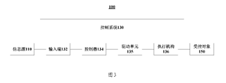
- FIG. 3 shows a schematic diagram of an application scenario according to an embodiment of the present application.
- the application scenario shown in FIG. 3 is the device 100 , which may include, but is not limited to, vehicles, machines, and the like, for example.
- the device 100 includes an information source 110 , a control system 130 and a controlled object 150 .
- the control system 130 is connected to the information source 110 and the controlled object 150, respectively.
- Information sources 110 may be various devices that generate information and/or collect information.
- the information source 110 may include, but is not limited to, a steering wheel torque angle sensor of the vehicle, a motor position sensor, a vehicle speed sensor, and/or a controller area network (Controller Area Network) for providing vehicle signal input of the vehicle. Area Network, CAN) bus, etc.
- a controller area network Controller Area Network
- the control system 130 is used to generate control signals to control the controlled object 150 according to the information from the information source 110 .
- the control system 130 may be, for example, but not limited to, an Electric Power Steering (EPS) system, an engine controller system, a motor controller system, a brake controller system, and the like.
- EPS Electric Power Steering
- the control system 130 may include an input 132 , a controller 134 , a drive unit 135 and an actuator 136 .
- Input 132 is used to receive information from information source 110 and send it to controller 134 .
- the controller 134 is configured to generate a control signal according to the information received from the input terminal 132 and output the generated control signal to the driving unit 135 .
- the driving unit 135 is used for controlling the operation of the actuator 136 according to the control signal from the controller 134, so that the controlled object 150 performs a predetermined operation.
- the actuator 136 may be, for example, a motor or the like.
- the controlled object 150 is an object controlled by the controller 134 of the control system 130 .
- the controlled object 150 may be, but is not limited to, a steering wheel of the vehicle, an engine that uses fuel to power the vehicle, a motor that uses electrical energy to power the vehicle, a brake, and the like.
- FIG. 4A shows a flowchart of a control method according to an embodiment of the present application.
- the control method 400 shown in FIG. 4A is used for a first ECU to monitor a second ECU, wherein the first ECU and the second ECU may be, for example, but not limited to, the ECU 630A in the EPS system 600 shown in FIG. 6 , respectively. and ECU 630B, or the first ECU and the second ECU may be, for example, but not limited to, ECU 630B and ECU 630A, respectively.
- the control method 400 may include steps S402-S414.
- step S402 the first ECU receives the first input signal and the second input signal.
- the first input signal and the second input signal may be provided by, for example, the input terminal 132 shown in FIG. 3 .
- the input terminal 132 may be a single input terminal, in which case, the first input signal and the second input signal may be received by the single input terminal, eg, from the information source 110, and then provided to the first input terminal respectively.
- an ECU and the second ECU may be provided to the input terminal 132 .
- the input 132 may comprise a first input and a second input, in which case the first input signal may be received by the first input, eg from the information source 110 and then provided to the first input, respectively An ECU and the second ECU, and the second input signal may be received by the second input, eg from an information source 110 and then provided to the first ECU and the second ECU, respectively.
- the first input signal and the second input signal may include different information according to different control systems in which the first ECU and the second ECU are located.
- the first input signal and the second input signal may include, but are not limited to, from a steering wheel torque angle sensor , motor position sensor, vehicle speed sensor and/or CAN bus etc.
- step S406 the first ECU outputs first information based on the first input signal, and provides the first information to the second ECU.
- step S410 the first ECU receives second information from the second ECU, the second information is output by the second ECU based on the second input signal.
- the first information may, for example, but not be limited to, include a first control signal to be provided to a first drive unit of a first actuator controlled by the first ECU, or the first control signal and the first control signal having the State parameters of equipment (eg, vehicles, etc.) of the first ECU.
- the second information may, for example, but not be limited to, include a second control signal to be provided to a second drive unit of a second actuator controlled by the second ECU, or the second control signal and the second control signal having the State parameters of equipment (eg, vehicles, etc.) of the second ECU.
- the state parameters may include, for example, B-MotPhsCur (phase current), B-MotPhsVolt (phase voltage), B-MPSRotSpd (motor angular velocity), etc. shown in FIG. 8 .
- the first actuator and the second actuator may be the same actuator, or may belong to different actuators.
- step S414 the first ECU detects the functional status of the second ECU based on the second input signal and the second information.
- the functional status may, for example, indicate whether the function of the second ECU is normal, whether a malfunction occurs, and the like.
- the first ECU and the second ECU belong to different computing platforms, and the first ECU's knowledge of the functional status of the second ECU is detected by the first ECU itself The functional status of the second ECU is implemented. Therefore, even if the second ECU has a fault or failure that cannot be diagnosed by itself (for example, a failure or failure due to power supply, communication, Analog to Digital Converter (ADC), crystal oscillator, short circuit, etc.) , the first ECU can also detect that the second ECU is faulty, thereby improving the coverage of fault diagnosis.
- ADC Analog to Digital Converter
- the first information is provided to the second ECU via a first redundant communication channel.
- the first redundant communication channel may be, for example, but not limited to, the redundant communication channel 660A shown in FIG. 6 and the like.
- the use of redundant communication channels to transmit information can improve the reliability of information transmission and interaction, on the other hand, it is equivalent to increasing the communication check, so that communication failures and ECU functional failures can be distinguished, reducing communication failures. Unnecessary shutdown of the actuator due to misunderstanding of a malfunction of the ECU.
- the second information is received by the first ECU via a second redundant communication channel.
- the second redundant communication channel may be, for example, but not limited to, the redundant communication channel 660A shown in FIG. 6 and the like.
- the use of redundant communication channels to transmit information can improve the reliability of information transmission and interaction, on the other hand, it is equivalent to increasing the communication check, so that communication failures and ECU functional failures can be distinguished, reducing communication failures. Unnecessary shutdown of the actuator due to misunderstanding of a malfunction of the ECU.
- the first input signal is received by the first ECU via a third redundant communication channel.
- the third redundant communication channel may be, for example, but not limited to, the redundant communication channel 660C shown in FIG. 6 and the like.
- the redundant communication channel is used to transmit the input signal.
- the ECU can continue to use the input signal transmitted by the other communication channels in the redundant communication channel. , which can increase the redundancy of the system and the reliability of the signal.
- the second input signal is received by the first ECU via a fourth redundant communication channel.
- the fourth redundant communication channel may be, for example, but not limited to, the redundant communication channel 660D shown in FIG. 6 and the like.
- the redundant communication channel is used to transmit the input signal.
- the electronic control unit can continue to use the other communication channels in the redundant communication channel to transmit the input signal. input signal, which can increase the redundancy of the system and the reliability of the signal.
- control method 400 may further include step S418.
- step S4108 upon detecting that the function of the second ECU is abnormal, the first ECU sends a failure notification to the second ECU indicating that the second ECU has failed.
- the second ECU can learn in time even if it cannot detect the failure of the second ECU. It has malfunctioned.
- control method 400 may further include step S422 or step S426.
- step S422 while the failure notification is sent, the first ECU outputs a first indication signal to the drive unit of the actuator controlled by the second ECU, the first indication signal instructing the drive unit A first operation is performed on the actuator.
- the first operation may be, for example, a failsafe operation mentioned herein, which may include, for example, shutting down the actuator, downgrading the actuator, restarting the actuator, and the like.
- the first ECU detects that the function of the second ECU is abnormal, it sends an instruction signal to the drive unit of the actuator controlled by the second ECU, so that the drive unit can respond to the actuator.
- Performing the corresponding fail-safe operation can prevent the second ECU from performing a dangerous operation on the controlled object via the actuator due to the failure or failure that may not have been diagnosed by the second ECU itself.
- step S426 if the drive unit of the actuator controlled by the second ECU has not performed the corresponding operation after a predetermined period of time has elapsed since the failure notification was sent, the first ECU outputs the output to the drive unit A second indication signal, the second indication signal instructs the drive unit to perform a second operation on the actuator.
- the second operation may be, for example, a failsafe operation mentioned herein, which may include, for example, shutting down the actuator, downgrading the actuator, restarting the actuator, and the like.
- the driver is sent to the driver
- the unit sends an instruction signal, so that the drive unit performs a corresponding fault operation on the actuator, which can prevent the actuator from performing a dangerous operation on the controlled object under the condition of complete failure of the second ECU.
- step S414 may include step S4142 and step S4144.
- step S4142 the first ECU calculates a first state parameter of a device having the second ECU according to the second input signal and the second information.
- step S4144 the first ECU determines the functional status of the second ECU according to the first state parameter and the first parameter threshold.
- the first state parameter may include, but is not limited to, the transverse direction of the vehicle.
- the first parameter threshold may include, but is not limited to, the maximum allowable yaw rate and the center of mass sideslip of the vehicle at the current vehicle speed and front wheel angle.
- the first ECU detects the functional status of the second ECU by means of the state parameters of the equipment having the second ECU, and can accurately determine whether the function of the second ECU has malfunctioned or failed.
- step S4142 may include: the first ECU checking the second input signal and the second information; and, when the checking result indicates the second input signal and the second information When valid, the first ECU calculates the first state parameter according to the second input signal and the second information.
- the first ECU checks the validity of the used input signals and information, which can prevent misjudgment of the functional status of the second ECU due to invalid input signals and information.
- step S4142 may include: the first ECU calculates, by the first ECU, one of the following values of the vehicle according to the second input signal and the second information. Describe the first state parameters: electric power steering linearization model, vehicle stability model, motor model, electric power steering linearization model and vehicle stability model, electric power steering linearization model and motor model, vehicle stability model and motor model , and, electric power steering linearization model, vehicle stability model, and motor model.
- the state parameters of the vehicle can be accurately calculated.
- FIG. 4B shows a flowchart of a monitoring method for a controller according to an embodiment of the present application.
- the monitoring method 450 shown in FIG. 4B is used for the controller A including the first ECU and the second ECU.
- the controller A may be, for example, but not limited to, a controller formed by the ECU 630A and the ECU 630B in the EPS system 600 shown in FIG. 6 , or the like.
- the monitoring method 450 may include steps S452-S468.
- step S452 the first ECU and the second ECU of the controller A receive the first input signal and the second input signal.
- the first input signal and the second input signal may be provided by, for example, the input terminal 132 shown in FIG. 3 .
- the input terminal 132 may be a single input terminal, in which case the first input signal and the second input signal may be received by the single input terminal, eg from the information source 110, and then provided to the controller A respectively the first ECU and the second ECU.
- the input 132 may comprise a first input and a second input, in which case the first input signal may be received by the first input, eg from the information source 110 and then provided to the controller A, respectively.
- the first ECU and the second ECU of the controller A, and the second input signal may be received by the second input, eg from the information source 110 and then provided to the first ECU and the second ECU of the controller A, respectively.
- the first input signal and the second input signal may include different information according to different control systems in which the controller A is located.
- the first input signal and the second input signal may include, but are not limited to, from a steering wheel torque angle sensor, a motor position sensor, a vehicle speed sensor and/or or CAN bus etc. data.
- step S456 the first ECU of the controller A outputs first information based on the first input signal, and provides the first information to the second ECU of the controller A.
- step S460 the second ECU of the controller A outputs second information based on the second input signal, and provides the second information to the first ECU of the controller A.
- the first information may, for example, but not be limited to, include a first control signal to be provided to the first drive unit of the first actuator controlled by the first ECU of the controller A, or the first control signal and a State parameters of controller A's equipment (eg, vehicle, etc.).
- the second information may, for example, but not be limited to, include a second control signal to be provided to the second drive unit of the second actuator controlled by the second ECU of the controller A, or the second control signal and a State parameters of controller A's equipment (eg, vehicle, etc.).
- the state parameters may include, for example, B-MotPhsCur (phase current), B-MotPhsVolt (phase voltage), B-MPSRotSpd (motor angular velocity), etc. shown in FIG. 8 .
- the first actuator and the second actuator may be the same actuator, or may belong to different actuators.
- step S464 the first ECU of the controller A detects the functional status of the second ECU of the controller A based on the second input signal and the second information from the second ECU of the controller A.
- step S468 the second ECU of the controller A detects the functional status of the first ECU of the controller A based on the first input signal and the first information from the first ECU of the controller A.
- the functional status may, for example, indicate whether the functions of the first ECU and the second ECU of the controller A are normal, whether there is a failure, and the like.
- the first ECU and the second ECU of the controller A belong to different computing platforms, and the first ECU of the controller A understands the functional status of the second ECU of the controller A by the controller A
- the first ECU of the controller A personally detects the functional status of the second ECU of the controller A, and the knowledge of the second ECU of the controller A to the functional status of the first ECU of the controller A is realized by the first ECU of the controller A.
- the second ECU detects the functional status of the first ECU of the controller A by itself.
- the second ECU of controller A will It can detect the failure of the first ECU of controller A, and similarly, even if the second ECU of controller A has a failure or failure that cannot be diagnosed by itself (for example, due to power supply, communication, ADC, crystal oscillator, short circuit, etc.) fault or failure), the first ECU of controller A can also detect that the second ECU of controller A is faulty, thereby improving the coverage of fault diagnosis.
- the first information is provided to the second ECU of controller A via a first redundant communication channel.
- the first redundant communication channel may be, for example, but not limited to, the redundant communication channel 660A shown in FIG. 6 and the like.
- the use of redundant communication channels to transmit information can improve the reliability of information transmission and interaction, on the other hand, it is equivalent to increasing the communication check, so that communication failures and controller function failures can be distinguished, reducing communication failures. Unnecessary shutdown of the actuator due to misinterpretation of a malfunction of the controller.
- the second information is provided to the first ECU of controller A via a second redundant communication channel.
- the second redundant communication channel may be, for example, but not limited to, the redundant communication channel 660A shown in FIG. 6 and the like.
- the use of redundant communication channels to transmit information can improve the reliability of information transmission and interaction, on the other hand, it is equivalent to increasing the communication check, so that communication failures and controller function failures can be distinguished, reducing communication failures. Unnecessary shutdown of the actuator due to misinterpretation of a malfunction of the controller.
- the first input signal is received by the first ECU and the second ECU of controller A via a third redundant communication channel.
- the third redundant communication channel may be, for example, but not limited to, the redundant communication channel 660C shown in FIG. 6 and the like.
- the redundant communication channel is used to transmit the input signal.
- the ECU can continue to use the input signal transmitted by the other communication channels in the redundant communication channel. , which can increase the redundancy of the system and the reliability of the signal.
- the second input signal is received by the first ECU and the second ECU of controller A via a fourth redundant communication channel.
- the fourth redundant communication channel may be, for example, but not limited to, the redundant communication channel 660D shown in FIG. 6 and the like.
- the redundant communication channel is used to transmit the input signal.
- the ECU can continue to use the input signal transmitted by the other communication channels in the redundant communication channel. , which can increase the redundancy of the system and the reliability of the signal.
- the monitoring method 450 may further include step S472.
- step S472 when it is detected that the function of the first ECU of the controller A is abnormal, the second ECU of the controller A sends the first ECU of the controller A to the first ECU of the controller A to indicate the failure of the first ECU of the controller A. Failure notification.
- the first ECU of the controller A can fail to detect the presence of itself even if In the case of failure, it can also be informed in time that a failure has occurred.
- the monitoring method 450 may further include step S476.
- step S476 when it is detected that the function of the second ECU of the controller A is abnormal, the first ECU of the controller A sends the second ECU of the controller A to the second ECU of the controller A to indicate that the second ECU of the controller A is malfunctioning Failure notification.
- the first ECU of the controller A sending a failure notification to the second ECU of the controller A when it detects that the function of the second ECU of the controller A is abnormal, the second ECU of the controller A can fail to detect the presence of itself even if In the case of failure, it can also be informed in time that a failure has occurred.
- the monitoring method 450 may further include step S480 or step S484.
- step S480 while sending the first fault notification, the second ECU of the controller A outputs a first indication signal to the first drive unit of the first actuator controlled by the first ECU of the controller A, the first The indication signal instructs the first drive unit to perform a first operation on the first actuator.
- the first operation may be, for example, a failsafe operation mentioned herein, which may include, for example, shutting down the first actuator, downgrading the first actuator, restarting the first actuator, and the like.
- the second ECU of the controller A sends an instruction signal to the first drive unit of the first actuator corresponding to the first ECU of the controller A when it detects the function of the first ECU of the controller A is abnormal, so as to Making the first drive unit perform a corresponding fail-safe operation on the first actuator can prevent the first ECU of the controller A from controlling the controller A via the corresponding actuator due to the failure or failure that may not have been diagnosed by itself. object to perform a dangerous operation.
- step S484 if the first drive unit of the first actuator controlled by the first ECU of the controller A has not performed the corresponding operation after the first predetermined period of time has passed since the first failure notification was sent, control the The second ECU of device A outputs a third instruction signal to the first drive unit, the third instruction signal instructs the first drive unit to perform a third operation on the first actuator.
- the first drive unit of the first actuator associated with the first ECU of the controller A has not yet executed after the first ECU of the controller A is notified of its failure by the second ECU of the controller A and a predetermined period of time has elapsed
- an instruction signal is sent to the first drive unit, so that the first drive unit performs a corresponding fail-safe operation on the first actuator, which can prevent the first drive unit in the case of complete failure of the first ECU of the controller A.
- the actuator performs a dangerous operation on an object controlled by the controller.
- the monitoring method 450 may further include step S488 or step S492.
- step S488 while sending the second fault notification, the first ECU of the controller A outputs a second indication signal to the second drive unit of the second actuator controlled by the second ECU of the controller A, the second The indication signal instructs the second driving unit to perform a second operation on the second actuator.
- the second operation may be, for example, a failsafe operation mentioned herein, which may include, for example, shutting down the second actuator, downgrading the second actuator, restarting the second actuator, and the like.
- the first ECU of the controller A sends an instruction signal to the second drive unit of the second actuator corresponding to the second ECU of the controller A when it detects the function of the second ECU of the controller A is abnormal, so as to Making the second drive unit perform a corresponding fail-safe operation on the second actuator can prevent the second ECU of the controller A from controlling the controller A via the corresponding actuator due to the fact that the second ECU of the controller A may not diagnose its own failure or failure. object to perform a dangerous operation.
- step S492 if the second drive unit of the second actuator controlled by the second ECU of the controller A has not performed the corresponding operation after the second predetermined period of time has elapsed since the second failure notification was sent, control the The first ECU of device A outputs a fourth instruction signal to the second drive unit, the fourth instruction signal instructs the second drive unit to perform a fourth operation on the second actuator.
- the second drive unit of the second actuator associated with the second ECU of the controller A has not yet executed after the first ECU of the controller A notifies the second ECU of the controller A of its failure and after a predetermined period of time has elapsed
- an instruction signal is sent to the second drive unit, so that the second drive unit performs a corresponding failsafe operation on the second actuator, which can prevent the second The actuator performs a dangerous operation on an object controlled by the controller.
- step S464 may include step S4642 and step S4644.
- step S4642 the first ECU of the controller A calculates the first state parameter of the device with the controller A according to the second input signal and the second information.
- step S4644 the first ECU of the controller A determines the functional status of the second ECU of the controller A according to the first state parameter and the first parameter threshold.
- the first state parameters may include, but are not limited to, the yaw rate and the center of mass of the vehicle.
- the first parameter threshold value may include, but is not limited to, the maximum allowable yaw rate and center of mass slip angle of the vehicle under the current vehicle speed and front wheel turning angle, for example.
- the first ECU of the controller A detects the functional status of the second ECU of the controller A by means of the state parameters of the equipment containing the controller A, and can accurately determine whether the function of the second ECU of the controller A fails or not. invalid.
- the first state parameter, etc. for the calculation of the above-mentioned first state parameter, etc., reference may be made to the following detailed description.
- step S4642 includes: the first ECU of the controller A checks the second input signal and the second information; and, when the check result indicates that the second input signal and the second When the information is valid, the first ECU of the controller A calculates the first state parameter according to the second input signal and the second information.
- the first ECU of the controller A checks the validity of the used second input signal and the second information, which can prevent misjudgment of the functional status of the second ECU of the controller A due to an invalid input signal.
- step S468 may include steps S4682 and S4684.
- step S4682 the second ECU of the controller A calculates the second state parameter of the device with the controller A according to the first input signal and the first information.
- step S4684 the second ECU of the controller A determines the functional status of the first ECU of the controller A according to the second state parameter and the second parameter threshold.
- the second state parameters may include, but are not limited to, the yaw rate and the center of mass of the vehicle.
- the second parameter threshold may include, but is not limited to, the maximum allowable yaw rate and center of mass slip angle of the vehicle at the current vehicle speed and front wheel angle.
- the second ECU of the controller A detects the functional status of the first ECU of the controller A by means of the state parameters of the equipment containing the controller A, and can accurately determine whether the function of the first ECU of the controller A fails or not. invalid.
- the second state parameter, etc. reference may be made to the following detailed description.
- step S4682 includes: the second ECU of the controller A checks the first input signal and the first information; and, when the check result indicates that the first input signal and the first When the information is valid, the second ECU of the controller A calculates the second state parameter according to the first input signal and the first information.
- the second ECU of the controller A checks the validity of the used first input signal and the first information, which can prevent misjudgment of the functional status of the first ECU of the controller A due to an invalid input signal.
- the device having the controller A includes a vehicle
- step S4642 includes: the first ECU of the controller A calculates one of the following according to the second input signal and the second information
- the first state parameters of the vehicle electric power steering linearization model, vehicle stability model, motor model, electric power steering linearization model and vehicle stability model, electric power steering linearization model and motor model, vehicle stability Performance model and motor model, as well as electric power steering linearization model, vehicle stability model and motor model.
- the state parameters of the vehicle can be accurately calculated.
- the device having the controller A includes a vehicle
- step S4682 includes: the second ECU of the controller A uses one of the following to calculate according to the first input signal and the first information
- the second state parameter of the vehicle electric power steering linearization model, vehicle stability model, motor model, electric power steering linearization model and vehicle stability model, electric power steering linearization model and motor model, vehicle stability Performance model and motor model, as well as electric power steering linearization model, vehicle stability model and motor model.
- the state parameters of the vehicle can be accurately calculated.
- FIG. 5A shows a schematic diagram of a controller according to an embodiment of the present application.
- the controller 500 includes a first ECU 510 and a second ECU 520.
- the first ECU 510 and the second ECU 520 respectively perform the operation performed by the first ECU of the controller A and the operation performed by the second ECU of the controller A in the control method 400 shown in FIG. 4A .
- ECU refers to a control device composed of integrated circuits for realizing a series of functions such as data analysis, processing and transmission.
- an embodiment of the present application provides an ECU 550, and the ECU 550 may include a microcomputer (microcomputer) 552, an input circuit 554, an output circuit 556 and an analog-to-digital (A/D) converter 558.
- the microcomputer 552 is connected to the input circuit 554 and the output circuit 556, respectively, and the A/D converter 558 is connected to the microcomputer 552 and the input circuit 554, respectively.
- the main function of the input circuit 554 is to preprocess the input signal (for example, the signal from the sensor).
- Different input signals have different processing methods.
- the input circuit may include an input circuit processing analog signals and an input circuit processing digital signals.
- the main function of the A/D converter 558 is to convert the analog signal into a digital signal.
- the analog signal is preprocessed by the corresponding input circuit 554 and then input to the A/D converter 558 for processing and converted into a digital signal that the microcomputer 552 can accept.
- the A/D converter 558 may be omitted.
- the output circuit 556 is a device that establishes the connection between the microcomputer 552 and the actuator. Its function is to convert the processing result sent by the microcomputer 552 into a control signal to drive the actuator to work.
- the output circuit 556 generally adopts a power transistor, which controls the electronic circuit of the actuator by turning on or off according to the instructions of the microcomputer.
- the microcomputer 552 includes a central processing unit (CPU) 5522, a memory 5524, and an input/output (I/O) interface 5526.
- the CPU 5522 is connected to the memory 5524 and the I/O interface 5526 through a bus, and is connected to each other. information can be exchanged through the bus.
- the memory 5524 may be memory such as read-only memory (ROM) or random access memory (RAM).
- the I/O interface 5526 is a connection circuit for exchanging information between the CPU 5522 and the input circuit 554, the output circuit 556 or the A/D converter 558. Specifically, the I/O interface 5526 can be divided into a bus interface and a communication interface.
- the memory 5524 stores a computer program, and the CPU 5522 invokes the computer program in the memory 5524 to execute the control method 400 described in the corresponding embodiment of FIG. 4A .
- the memory 5524 may be, for example, but not limited to, random access memory, flash memory, read-only memory, programmable read-only memory or electrically erasable programmable memory, magnetic disk or optical disk, and the like.
- the CPU5522 can be, but is not limited to, a general-purpose processor, a digital signal processor (DSP), an application specific integrated circuit (ASIC), a field programmable gate array (FPGA), or other Programming logic devices, discrete gate or transistor logic devices, discrete hardware components.
- a general-purpose processor may be either a microprocessor or the processor, any conventional processor, or the like.
- Document 1 Standardized E-Gas Monitoring Concept for Gasoline and Diesel Engine Control Units-Version 6.0, 2015-07-13 discloses a three-layer monitoring model for engine control units, which includes Level 1 layer (functional calculation layer ), Level 2 (function monitoring layer) and Level 3 (controller monitoring layer).
- the redundant cross monitoring layer and redundant dual system are designed on the basis of the three-layer monitoring model disclosed in Document 1. Interactive mode, so that the fault diagnosis coverage of the EPS system is wider under the same safety mechanism, or the EPS system can achieve the same fault diagnosis effect and ASIL level with fewer bottom-level safety mechanisms by adding a few top-level safety mechanisms.
- FIG. 6 shows a schematic diagram of the architecture of an EPS system according to an exemplary implementation of the present application.
- the EPS system 600 includes an A system and a B system.
- the modules included in the A system and the B system are the same, and both have signal input terminals, ECUs, and redundant motors as actuators.
- the A system includes a signal input end 610A, an ECU 630A, a drive unit 645A and a redundant motor 650A
- the B system includes a signal input end 610B, an ECU 630B, a drive unit 645B and a redundant motor 650B.
- the ECU 630A is connected to the signal input terminal 610A and the redundant motor 650A, respectively.
- the ECU 630B is connected to the signal input terminal 610B and the redundant motor 650B, respectively.
- ECU 630A and ECU 630B together form the controller of EPS system 600.
- the input signal provided by the signal input terminal 610A may include, for example, the sensor input signal, the vehicle input signal and the A system output of the drive unit 645A
- the input signal provided by the signal input terminal 610B may include, for example, the sensor input signal, the vehicle input signal and the drive unit.
- the sensor input signal may include, but is not limited to, a steering wheel torque and angle sensor (Torque and Angle Sensor: TAS) signal, a motor position sensor (Motor Position Sensor: MPS) signal, and the like.
- the vehicle input signal can be, for example, but not limited to, a controller area network (Controller Area Network: CAN) signal.
- a system output may include, for example, a control signal (such as, but not limited to, a voltage pulse width modulation signal, etc.) output by the drive unit 645A to the redundant motor 650A, or the current of each phase output by the drive unit 645A to the redundant motor 650A.
- the B system output may include, for example, a control signal (such as, but not limited to, a voltage PWM signal, etc.) output by the drive unit 645B to the redundant motor 650B, or the current of each phase output by the drive unit 645B to the redundant motor 650B.
- the ECU 630A and the ECU 630B each include three units, wherein the ECU 630A includes a first application program (Application Program) unit 632A, a basic software (Basic Software) unit 640A and a second application program unit 644A, and the ECU 630B includes a first Application unit 632B, base software unit 640B, and second application unit 644B.
- the first application unit 632A and the first application unit 632B each have the functions of both the Level 1 function calculation layer and the Level 2 function monitoring layer in Document 1.
- the basic software unit 640A and the basic software unit 640B correspond to the Level 3 controller monitoring layer in Document 1, respectively.
- the controller of the EPS system 600 formed by the ECU 630A and the ECU 630B further includes redundant communication channels 660A, 660C and 660D, wherein the redundant communication channel 660A is used to connect the ECU 630A and the ECU 630B, and the redundant communication channel 660C inputs signals Terminal 610A is connected to ECU 630A and ECU 630B, and redundant communication channel 660D connects signal input terminal 610B to ECU 630A and ECU 630B.
- the redundant communication channels 660A, 660C and 660D each include at least two communication channels. For the relationship between each unit, take system A as an example, and look at the signal transmission path from the signal input end to the controller end.
- One channel of redundancy of the input signal (for example, TAS signal, CAN signal, MPS signal, system A output, etc.) provided by the signal input terminal 610A of the A system is used as the signal input of the ECU 630A of the A system, and enters through the redundant communication channel 660C. to the base software unit 640A for use by the first application unit 632A.
- the other way of the input signal provided by the signal input terminal 610A of the A system enters the basic software unit 640B of the ECU 630B of the B system through the redundant communication channel 660C, so as to be provided to the second application program unit 644B of the ECU 630B for use.
- a corresponding function calculation is performed using the received input signal to output information IA, wherein the information IA may include a control signal, or, the control signal and a state parameter of the vehicle.
- the control signals included in the information IA are provided to the drive unit 645A to drive the redundant motor 650A.
- the information IA is first provided by the first application unit 632A to the base software unit 640B of the ECU 630B via the redundant communication channel 660A, and then by the base software unit 640B to the second application unit 644B.
- the first application program unit 632A also uses the same source input signal to verify the information IA output by the first application program unit 632A at the functional level to detect the functional status of the ECU 630A.
- the second application unit 644B of the B system monitors the A system, that is, the second application unit 644B of the B system combines the input signal from the signal input terminal 610A of the A system with the information from the first application unit 632A of the ECU 630A IA2
- the information IA output by the first application unit 632A of the ECU 630A of the A system is verified at the functional level based on the computing platform provided by the ECU 630B of the B system.
- the redundant communication channel 660A is used to transmit information between the ECU 630A and the ECU 630B.
- the redundant communication channel 660C is used to provide signals from external sensors, etc. to the ECU 630A and ECU 630B.
- the ECU can also continue to use the input signal transmitted by other communication channels in the redundant communication channel, which can increase the redundancy of the system and the reliability of the signal.
- the first application unit 632A of the ECU 630A can monitor many faults of the ECU 630A itself.
- the second application program unit 644B of the ECU 630B can monitor some faults or failures that cannot be monitored by the first application program unit 632A, and the failures or failures include, for example, due to power supply, communication, ADC, crystal oscillator, short circuit, etc. failure or failure caused.
- the monitoring logic of the first application unit 632A and the second application unit 644B is similar, and their monitoring contents may be the same or different.
- the second application unit 644B can monitor variables and states of a macro or top-level state, for example, but not limited to, the first application unit 632A monitors certain binary numbers or subsystems. Certain states, while the second application unit 644B looks at System A and monitors certain variables that are more physically meaningful.
- One channel of redundancy of the input signal (for example, TAS signal, CAN signal, MPS signal, system B output, etc.) provided by the signal input terminal 610B of the B system is used as the signal input of the ECU 630B of the B system, and enters through the redundant communication channel 660D. to the base software unit 640B for use by the first application program unit 632B.
- the other way of the input signal provided by the signal input terminal 610B of the B system enters the basic software unit 640A of the ECU 630A of the A system through the redundant communication channel 660D, so as to be provided to the second application program unit 644A of the ECU 630A for use.
- a corresponding function calculation is performed using the received input signal to output information IB, where the information IB may include a control signal, or, the control signal and a state parameter of the vehicle.
- the control signals included in the information IB are provided to the drive unit 645B to drive the redundant motor 650B.
- the information IB is first provided by the first application unit 632B to the base software unit 640A of the ECU 630A via the redundant communication channel 660A, and then by the base software unit 640A to the second application unit 644A.
- the first application program unit 632B also uses the same source input signal to verify the information IB output by the first application program unit 632B at the functional level to detect the functional status of the ECU 630B.
- the second application unit 644A of the A system monitors the B system, that is, the second application unit 644A of the A system combines the input signal from the signal input terminal 610B of the B system with the information IB2 from the first application unit 632B of the ECU 630B
- the information IB output by the first application unit 632B of the ECU 630B of the B system is verified at the functional level based on the computing platform provided by the ECU 630A of the A system. , to detect the functional status of the ECU 630B (for example, whether an isolated battle occurs, whether it fails, etc.).
- the first application unit 632B of the ECU 630B can monitor many faults of the ECU 630B itself.
- the second application program unit 644A of the ECU 630A can monitor some faults or failures that cannot be monitored by the first application program unit 632B, and the failures or failures include, for example, due to power supply, communication, ADC, crystal oscillator, short circuit, etc. failure or failure caused.
- the monitoring logic of the first application unit 632B and the second application unit 644A is similar, and their monitoring contents may be the same or different.
- the second application unit 644A can monitor variables and states of a macro or top-level state, for example, but not limited to, the first application unit 632B can monitor certain binary numbers or subsystems while the second application unit 644A looks at the B system and monitors certain variables with relatively strong physical meaning.
- the fail-safe operation is a safety-related execution operation, such as turning off the motor, downgrading the motor, restarting the motor, and the like.
- the control command is a control signal output by the controller to the drive unit of the motor as the actuator.
- the control command channel of the A system is used to provide the control signal output by the first application program unit 632A of the ECU 630A to the drive unit 645A to drive the motor 650A.
- the base software unit 640A of the ECU 630A judges whether the ECU 630A is based on the monitoring of the hardware of the ECU 630A (such as, but not limited to, registers, memory space, etc.) and the underlying software (such as, but not limited to, the timing of the program, etc.).
- a failure or failure occurs, and when the ECU 630A fails or fails, the basis for sending a failure notification indicating failure or failure of the ECU 630A and including failure information (cause) and failure level to the ECU 630B via the redundant communication channel 660A
- the software unit 640B outputs an instruction signal to the drive unit 645A through the fault protection operation channel A1 to instruct the motor 650A to perform a fault protection operation corresponding to the fault level.
- the base software unit 640A when receiving a failure notification from the second application program unit 644B of the ECU 630B for indicating that the ECU 630A is malfunctioning or failing and containing the failure information (cause) and the failure level, the base software unit 640A operates the channel through the failsafe A1 outputs to the drive unit 645A an instruction signal instructing it to perform a failsafe operation on the motor 650A corresponding to the failure level.
- the basic software unit 640A of the ECU 630A can provide a guarantee for the computing platform provided by the ECU 630A to the first application program unit 632A and the second application program unit 644A.
- the first application program unit 632A of the ECU 630A uses the computing platform provided by the ECU 630A to monitor the calculation result (that is, the information IA) of the first application program unit 632A of the ECU 630A, and when the calculation result is abnormal, the redundant
- the communication channel 660A sends a failure notification to the basic software unit 640B of the ECU 630B for indicating a failure or failure of the ECU 630A and including the failure information (cause) and the failure level, and outputs an indication to the drive unit 645A through the failsafe operation channel A2 It is an indication signal for the motor 650A to perform a fault protection operation corresponding to the fault level.
- the second application program unit 644B of the ECU 630B is based on the computing platform provided by the ECU 630B, and monitors the calculation result of the first application program unit 632A of the ECU 630A to detect the functional status of the ECU 630A, and when the detection finds that the function of the ECU 630A is abnormal , perform one of the following operations (I) and (II): (I) the second application program unit 644B of the ECU 630B uses the basic software unit 640B and the redundant communication channel 660A to indicate that the ECU 630A has failed or A failure notification that fails and contains the failure information (cause) and the failure level is sent to the basic software unit 640A, and at the same time the second application program unit 644B of the ECU 630B outputs to the drive unit 645A through the failsafe operation channel A3 indicating that it performs and the motor 650A.
- the second application unit 644B of the ECU 630B uses the basic software unit 640B and the redundant communication channel 660A to indicate the failure or failure of the ECU 630A and contains the fault information.
- (Cause) and failure level failure notification is sent to the basic software unit 640A, and then the second application program unit 644B of the ECU 630B monitors whether the drive unit 645A performs the corresponding fail-safe operation on the redundant motor 650A, and if the monitoring finds that a predetermined period of time has elapsed After that, the drive unit 645A has not performed the corresponding fail-safe operation on the redundant motor 650A, then the second application unit 644B of the ECU 630B outputs an instruction to the drive unit 645A through the fail-safe operation channel A3 to instruct the motor 650A to perform the corresponding fail-level operation on the motor 650A.
- the second application program unit 644B of the ECU 630B can first perform a redundancy check on the input signal and the information IA, and then monitor whether the overall function of the ECU 630A is normal according to certain physical laws and mathematical models after the redundancy check is passed.
- the controller side from the controller side to the actuator side also includes three fault protection operation channels (B1, B2, B3) and a control command channel.
- the control command channel of the B system is used to provide the control signal output by the first application program unit 632B of the ECU 630B to the drive unit 645B to drive the motor 650B.
- the controller side there are three sources for the failsafe operation of the redundant motor 650B: the basic software unit 640B of the ECU 630B, the first application program unit 632B of the ECU 630B, and the second application program unit 644A of the ECU 630A.
- the basic software unit 640B of the ECU 630B judges whether the ECU 630B is based on the monitoring of the hardware of the ECU 630B (such as, but not limited to, registers, memory space, etc.) and the underlying software (such as, but not limited to, the timing of the program, etc.).
- a failure or failure occurs, and when the ECU 630B fails or fails, the basis for sending a failure notification indicating failure or failure of the ECU 630B and including failure information (cause) and failure level to the ECU 630A via the redundant communication channel 660A
- the software unit 640A and, through the fail-safe operation channel B1, outputs to the drive unit 645B an instruction signal indicating that it performs a fail-safe operation corresponding to the fault level to the motor 650B.
- the base software unit 640B when receiving a failure notification from the second application program unit 644A of the ECU 630A indicating that the ECU 630B has failed or failed and containing the failure information (cause) and the failure level, the base software unit 640B operates the channel B1 through the failsafe An instruction signal is output to the drive unit 645B indicating that it performs a failsafe operation on the motor 650B corresponding to the failure level.
- the basic software unit 640B of the ECU 630B can provide a guarantee for the computing platform provided by the ECU 630B to the first application program unit 632B and the second application program unit 644B.
- the first application program unit 632B of the ECU 630B uses the computing platform provided by the ECU 630B to monitor the calculation result (that is, the information IB) of the first application program unit 632B of the ECU 630B, and when the calculation result is abnormal, the redundant
- the communication channel 660A sends a failure notification to the basic software unit 640A of the ECU 630A for indicating a failure or failure of the ECU 630B and including the failure information (cause) and the failure level, and outputs an indication to the drive unit 645B through the failsafe operation channel B2 It is an indication signal for the motor 650B to perform a fault protection operation corresponding to the fault level.
- the second application program unit 644A of the ECU 630A is based on the computing platform provided by the ECU 630A, and monitors the calculation result of the first application program unit 632B of the ECU 630B to detect the functional status of the ECU 630B, and when the detection finds that the function of the ECU 630B is abnormal
- one of the following operations (I) and (II) is performed: (I) the second application unit 644A of the ECU 630A uses, via the basic software unit 640A and the redundant communication channel 660A, to indicate that the ECU 630B has failed or A failure notification that fails and contains the failure information (cause) and the failure level is sent to the basic software unit 640B, and at the same time the second application unit 644A of the ECU 630A outputs to the drive unit 645B through the fail-safe operation channel B3 indicating that it performs and the motor 650B.
- the second application program unit 644A of the ECU 630A uses the basic software unit 640A and the redundant communication channel 660A to indicate the failure or failure of the ECU 630B and contains the fault information. (Cause) and failure level failure notification is sent to the basic software unit 640B, and then the second application program unit 644A of the ECU 630A monitors whether the drive unit 645B performs the corresponding failsafe operation on the redundant motor 650B, and if the monitoring finds that a predetermined period of time has elapsed After that, the drive unit 645B has not performed the corresponding fail-safe operation on the redundant motor 650B, then the second application unit 644A of the ECU 630A outputs an instruction to the drive unit 645B through the fail-safe operation channel B3 to instruct the motor 650B to perform the corresponding fail-level operation on the motor 650B.
- the second application program unit 644A of the ECU 630A can first perform a redundancy check on the input signal and the information IB, and then monitor whether the overall function of the ECU 630B is normal according to certain physical laws and mathematical models after the redundancy check is passed.
- the drive unit 645A From the actuator end to the signal input end, for the A system, the drive unit 645A generates the A system output to be provided to the redundant motor 650A according to the control signal output by the first application program 632A, wherein the A system output is provided in addition to the In addition to driving the redundant motor 650A to perform the desired operation, the redundant motor 650A is also sent back to the signal input terminal 610A through the signal line, so as to provide a basis for the calculation of the controller in the next sampling period.
- the drive unit 645B For the B system, the drive unit 645B generates the B system output to be provided to the redundant motor 650B according to the control signal output by the first application program 632B, wherein the B system output is provided to the redundant motor 650B in addition to driving the redundant motor 650B. In addition to the desired operation of the motor 650B, it is also sent back to the signal input terminal 610B through the signal line, so as to provide a basis for the calculation of the controller in the next sampling period.
- the design ideas can be summarized as follows. (1) Monitor and diagnose the other system by setting up a second application program unit in each system. (2) In the second application program unit, for example, the input signal is checked for redundancy and the overall function of the counterpart system is monitored according to certain physical laws and mathematical models, and when the function of the counterpart system is abnormal, the fault is used
- the protection operation channel independently shuts down, degrades or restarts the motors controlled by the opposite system to prevent failures such as steering loss, understeering, reverse steering, and steering lock.
- the monitoring function of the first application program unit of the system is in a parallel relationship with the second application program unit of the opposite system, wherein the second application program unit of the opposite system is provided by the opposite system.
- a functional check is performed on the calculation result of the first application program unit of the system on the computing platform, and the first application program unit of the system performs a function on the calculation result of the first application program unit of the system on the computing platform provided by the system. sex check.
- the basic software unit of each system monitors, for example, the sequence, registers, memory space, etc. of the program of the system, so as to provide reliability for the computing platform used by the first application program unit and the second application program unit of the system Assure.
- FIG. 7 shows a detailed schematic diagram of an EPS system according to an exemplary implementation of the present application.
- FIG. 7 only shows the part related to the monitoring of the A system, and the part related to the monitoring of the B system is similar to the part related to the monitoring of the A system, and will not be repeated here.
- the part related to the monitoring of the A system involves the first application unit 632A and the basic software unit 640A in the ECU 630A of the A system, and the basic software unit 640B and the second application unit 644B in the ECU 630B of the B system .
- the first application unit 632A includes a function calculation unit 634A and a function monitoring unit 636A.
- the function calculation unit 634A may include system management algorithms, power assist control algorithms, motor control algorithms, calibration parameters, etc., and update control signals according to demand instructions.
- the functional computing layer 634A can be equipped with complete and detailed diagnostic strategies and processing mechanisms.
- the function calculation unit 634A may include a signal detection module 6322A, a function calculation module 6324A, and a control output module 6326A.
- the signal detection module 6322A receives from the base software unit 640A an input signal (such as, but not limited to, TAS signal, MPS signal, CAN signal and/or from the signal input terminal 610A of the A system that has passed the signal verification of the base software unit 640A). system output of the drive unit 645A, etc.), and perform redundant signal detection on the received input signal.
- the redundant signal detection may include, but is not limited to, range checking, constraint relationship detection, and/or vital signal detection, for example. Range detection is used to detect whether the input signal is within a defined valid range and/or overflows. Constraint relationship detection is used to detect whether two sets of interrelated input signals satisfy a certain mathematical relationship. The life signal detection is used to detect whether the signal value is updated during communication. If the redundant signal detection result indicates that the received input signal is valid, the signal detection module 6322A sends the received input signal to the function calculation module 6324A.
- the function calculation module 6324A After receiving the input signal from the signal detection module 6322A, the function calculation module 6324A uses the received input signal and performs calculations by means of, for example, but not limited to, system management algorithms, power assist control methods, and/or motor control algorithms, etc., as required The command updates the control signal. In addition, the function calculation module 6324A can also use the received input signals to calculate the state parameters of the vehicle. Functional calculation module 6324A then provides information IA to control output module 6326A, where information IA may include only the control signal, or information IA may include the control signal and the calculated state parameter.
- the control output module 6326A outputs the control signal included in the information IA received from the function calculation module 6324A to the drive unit 645A to drive the redundant motor 650A, so as to realize the control of the redundant motor 650A.
- the control output module 6326A also provides the received information IA to the signal detection module 6362A of the function monitoring unit 636A and, via the redundant communication channel 660A, to the signal verification module 6402B in the basic software unit 640B of the ECU 630B, in order to After being verified at the signal verification module 6402B, the information IA is provided to the second application program unit 644B by the signal verification module 6402B.
- the function monitoring unit 636A is used to monitor the function calculation unit 634A. Through the input signal provided by the signal input terminal 610A of the A system, starting from the motor equation and the vehicle motion/dynamic equation, the torque is used as the excitation and the speed/acceleration as the response, and the difference between the actual torque and the allowable torque is compared. Monitoring, where the actual torque is derived from sensors and calculation methods, and the allowable torque is derived from the controller's decision based on the system state. There are preconditions that the function monitoring unit 636A can effectively monitor the execution state of the function computing unit 634A, that is, whether the function monitoring unit 636A is correct in principle, and whether the computing platform on which the function monitoring unit 636A is executed is reliable. For the former, it can be guaranteed through research, analysis and simulation during program design. For the latter, reliability assurance can be performed using the base software unit 640A.
- the function monitoring unit 636A includes a signal detection module 6362A, a model calculation module 6364A, a judgment mechanism module 6366A, a fault management module 6367A, and a fault processing module 6368A.
- the signal detection module 6362A receives from the base software unit 640A an input signal (such as, but not limited to, TAS signal, MPS signal, CAN signal and/or from the signal input terminal 610A of the A system that has passed the signal verification of the base software unit 640A).
- the system output of the drive unit 645B, etc. and receive the information IA from the control output module 6326A in the function calculation unit 634A, and based on the complete and detailed diagnosis strategy and processing mechanism that is equipped with the received input signal and information IA Perform redundant signal detection. If the redundant signal detection result indicates that the received input signal and information IA are valid, the signal detection module 6362A sends the received input signal and information IA to the model calculation module 6364A. If the redundant signal detection result indicates that the received input signal or information IA is invalid, the fault management mode is entered.
- an input signal such as, but not limited to, TAS signal, MPS signal, CAN signal and/or from the signal input terminal 610A of the A system that has
- the model calculation module 6364A After receiving the input signal and information IA from the signal detection module 6362A, the model calculation module 6364A utilizes the received input signal and information IA with the help of corresponding mathematical models (such as, but not limited to, the vehicle dynamics model, EPS Linearization model and/or motor model, etc.) to calculate the current state parameters of the vehicle, and provide the calculated current state parameters to the judgment mechanism module 6366A.
- the calculated current state parameter of the vehicle may be different from the received input signal and information IA, or the calculated current state parameter of the vehicle may be the received input signal and information IA.
- the judgment mechanism module 6366A compares the current state parameter of the vehicle from the model calculation module 6364A with a parameter reference value, which can be a fixed value or a calibrated MAP that varies with the input, or the parameter reference value can also be a certain Signal value (for example, the motor control command A sent by the application program needs to compare the actual motor torque with the motor command to see if there is unexpected acceleration or deceleration or runaway). If the comparison result shows that the current state parameter is greater than the parameter reference value, it indicates that the ECU 630A has a fault or failure, and thus enters the fault management mode.
- a parameter reference value which can be a fixed value or a calibrated MAP that varies with the input, or the parameter reference value can also be a certain Signal value (for example, the motor control command A sent by the application program needs to compare the actual motor torque with the motor command to see if there is unexpected acceleration or deceleration or runaway). If the comparison result shows that the current state parameter is greater than the parameter reference value, it
- the fault management module 6367A determines the fault level and sends the determined fault level to the fault handling module 6368A and, via the redundant communication channel 660A, to the basic software unit 640B of the ECU 630B for A failure notification indicating failure or failure of the ECU 630A and including failure information (cause) and the determined failure level.
- the fault processing module 6368A is configured to output instruction information to the drive unit 645A after receiving the determined fault level from the fault management module 6367A, so as to instruct the drive unit 645A to perform a fault corresponding to the determined fault level on the redundant motor 650A Protect operation.
- the basic software units 640A and 640B respectively provide reliability assurance for the computing platform provided by the ECU 630A and the computing platform provided by the ECU 630B. For this reason, the basic software units 640A and 640B monitor the software operation and hardware devices of the ECU 630A and ECU 630B respectively. , which includes monitoring of power supply, communication, memory, registers, program flow, etc., as well as monitoring the working status of the ECU as a whole through software and hardware watchdogs.
- the base software units 640A and 640B each have separate failover channels for shutting down, downgrading and restarting the ECU.
- the basic software unit 640A includes a signal verification module 6402A, a system monitoring module 6406A and a fault handling module 6408A.
- the system monitoring module 6406A may include a memory read/write monitoring module, an ADC/Input/Output (IO) monitoring module, a communication module, a watchdog response (Query/Answer, Q/A) module, a power check module and fault handling module.
- IO ADC/Input/Output
- Q/A watchdog response
- the basic software unit 640B includes a signal verification module 6402B, a system monitoring module 6406B and a fault handling module 6408B.
- the system monitoring module 6406B may include a memory read/write monitoring module, an ADC/IO monitoring module, a communication module, a watchdog Q/A module, a power check module and a fault handling module.
- each module in the basic software unit 640A and each module in the basic software unit 640B perform the same function, only each module in the basic software unit 640A is described below, and each module in the basic software unit 640B will not be repeated.
- the signal verification module 6402A of the basic software unit 640A may receive input signals (such as, but not limited to, TAS signals, MPS signals, and/or CAN signals, etc.) from the signal input terminal 610A via the redundant communication channel 660C, and the received The input signal is subjected to signal verification, and when the signal verification passes, the signal detection module 6322A in the function calculation unit 634A of the first application program unit 632A and the signal detection module in the function monitoring unit 636A of the first application program unit 632A are sent. The 6362A transmits the received input signal.
- input signals such as, but not limited to, TAS signals, MPS signals, and/or CAN signals, etc.
- the signal check may include, but is not limited to, a rolling count check (Rolling Counter), a cyclic redundancy check (Cyclic Redundancy Check, CRC), etc., wherein, the rolling count check is used to check whether there are lost frames and missing frames CRC is used to detect whether the data of the sender and the receiver are consistent.
- Rolling Counter Rolling Counter
- CRC Cyclic Redundancy Check
- the signal verification module 6402A of the base software unit 640A may receive, via the redundant communication channel 660A, a failure notification from the ECU 630B indicating that the ECU 630A has failed or failed and containing failure information (cause) and failure level, and, for Indicates that the ECU 630B is faulty or failed and contains the fault information (cause) and fault level of the fault notification, performs signal verification on the received fault notification, and when the signal verification passes, sends the received fault notification to the basic software Fault handling module 6408A of unit 640A.
- the signal verification module 6402A of the basic software unit 640A can receive the information IB output by the first application program unit 632B of the ECU 630B via the redundant communication channel 660A, perform signal verification on the received information IB, and when the signal verification When the verification is passed, the received information IB is sent to the second application unit 644A of the ECU 630A.
- the signal verification module 6402A of the basic software unit 640A may receive input signals (such as, but not limited to, TAS signals, MPS signals, and/or CAN signals, etc.) from the signal input terminal 610B via the redundant communication channel 660D, and for all The received input signal is subjected to signal verification, and when the signal verification passes, the received input signal is sent to the second application program unit 644A of the ECU 630A.
- input signals such as, but not limited to, TAS signals, MPS signals, and/or CAN signals, etc.
- the memory read-write monitoring module in the system monitoring module 6406A is used for random access memory (Random Access Memory, RAM), read-only memory (Read-Only Memory, ROM), flash memory ( Flash) to test whether the RAM works normally, the reliability of the data stored in the ROM, and whether the read and write functions are normal.
- the memory read/write monitoring module in the system monitoring module 6406A performs fragment detection every several sampling periods, and enters a fault management mode if an error occurs.
- the ADC/IO monitoring module in the system monitoring module 6406A is used to test whether the ADC and IO modules in the ECU 630A work normally, and whether the ADC and IO control units are configured correctly. If ADC conversion error or IO output error, the ECU 630A should be reset, and it can be started after troubleshooting.
- the communication module in the system monitoring module 6406A is used to test whether the CAN communication module and the SPI communication module are normal, whether the baud rate setting is correct, whether the configuration of the CAN communication module and the SPI communication module is correct, and whether the safety monitoring chip (System Basis Chip, SBC) communication is normal, etc.
- SBC System Basis Chip
- the watchdog Q/A module in the system monitoring module 6406A is used to test whether the watchdog timing and time configuration of the ECU 630A are correct, and monitor the real-time operating environment of the ECU hardware through the system periodic test task Q/A mechanism. Then turn off the motor and reset the ECU.
- Q/A periodically sends specific test tasks to the target module, for example, the SBC chip sends the test task to the ECU.
- the target module receives the test task, it outputs the test result according to the predetermined function and feeds it back to the sender, and then the SBC chip judges whether the program is running or not. correct and whether there are unexpected results. If the test result is passed, the system enters the periodic operation mode and periodic test mode. If the operation fails, a fault code will be reported and the system will enter the fault mode.
- the power check module in the system monitoring module 6406A is used to test and judge whether the voltage management of the ECU 630A is normal, whether the voltage of each key point is normal, and whether the output of the SBC and the voltage regulator is normal.
- the power check module in the system monitoring module 6406A periodically performs power supply monitoring, voltage monitoring, current monitoring, temperature monitoring, speed monitoring and torque monitoring.
- the hardware modules of the ECU 630A work normally and the system configuration is correct, and the system operating conditions are satisfied, so that the system can continue to operate. If the test of one or more of the above modules fails, the error code given by the module that fails the test needs to be recorded, and the system enters the fault management mode.
- the fault processing module 6408A can determine the fault level, and then output instruction information to the drive unit 645A to instruct the drive unit 645A to perform the fault protection corresponding to the determined fault level on the redundant motor 650A operation, and, via the redundant communication channel 660A, to send a failure notification to the base software unit 640B of the ECU 630B indicating that the ECU 630A has failed or failed and containing failure information (cause) and a failure level.
- failure processing module 6408A outputs instruction information to drive unit 645A to instruct drive unit 645A to The redundant motor 650A performs a failsafe operation corresponding to the failure level included in the received failure notification.
- the second application program unit 644B of the ECU 630B monitors and verifies the functional status of the ECU 630A according to the input signal from the signal input terminal 610A of the A system and the information IA from the first application program unit 632A in the ECU 630A of the A system .
- the second application unit 644B has the following features.
- the ECU 630B is a different computing platform from the ECU 630A, so when the ECU 630A fails due to power supply, communication, ADC, crystal oscillator and/or short circuit, etc., it cannot be detected or In the event of a failure, the second application program unit 644B located in the ECU 630B is able to diagnose such failures, reducing residual failures or failures, thereby increasing the fault diagnosis coverage.
- the first application unit 632A in the ECU 630A provides the information IA to the second application unit 644B through the redundant communication channel 660A, so the second application unit 644B does not mistake the communication failure as a function of the ECU 630A faults, thereby distinguishing communication faults from functional faults through redundant communication channels, reducing unnecessary shutdown of redundant motors due to mistaking communication faults for functional faults.
- the second application unit 644B has a fault operation channel for independent control of the redundant motor 650A.
- the second application program unit 644B includes a signal detection module 6442B, a model calculation module 6444B, a judgment mechanism module 6446B, a fault management module 6447B, and a fault processing module 6448B.
- the signal detection module 6442B receives, from the signal verification module 6402B of the basic software unit 640B, the input signal from the signal input terminal 610A of the A system (such as, but not limited to, TAS signal, MPS signal and / or CAN signal, etc.) and the information IA from the first application program unit 632A of the ECU 630A, and perform the aforementioned redundant signal detection on the received input signal and information IA. If the redundant signal detection result indicates that the received input signal and information IA are valid, the signal detection module 6442B sends the received input signal and information IA to the model calculation module 6444B. If the verification result indicates that the received input signal or information IA is invalid, the fault management mode is entered.
- the signal verification module 6402B of the basic software unit 640B receives, from the signal verification module 6402B of the basic software unit 640B, the input signal from the signal input terminal 610A of the A system (such as, but not limited to, TAS signal, MPS signal and / or CAN signal
- the model calculation module 6444B uses the input signal and information IA from the signal detection module 6442B to calculate the current state parameters of the vehicle, and provides the calculated state parameters to the judgment mechanism module 6446B.
- the judgment mechanism module 6446B compares the state parameter received from the model calculation module 6444B with the parameter reference value. If the comparison result shows that the received state parameter is greater than the parameter reference value, the fault management mode is entered.
- the fault management module 6447B determines the fault level and sends the determined fault level to the fault handling module 6448B and, via the base software unit 640B and the redundant communication channel 660A, to the base software unit of the ECU 630A
- the signal verification module 6402A of 640A sends a fault notification indicating that the ECU 630A has a fault or failure and includes fault information (cause) and the determined fault level, so that after the fault notification is verified at the signal verification module 6402A, It is provided by the signal verification module 6402A to the fault handling module 6408A of the base software unit 640A.
- the fault handling module 6448B may perform one of the following operations (I) and (II): (1) The fault handling module 6448B directly operates the channel A3 through the fault protection Send instruction information to the drive unit 645A to instruct the drive unit 645A to perform a failsafe operation corresponding to the determined failure level on the redundant motor 650A; (II) the fault management module 6447B sends the basic software unit 640A of the ECU 630A to the After the fault notification, the fault processing module 6448B starts to monitor the drive unit 645A, and if the monitoring finds that the drive unit 645A has not performed the corresponding fault protection operation on the redundant motor 650A after a predetermined period of time, the fault processing module 6448B passes the fault protection operation channel A3 Instruction information is sent to the drive unit 645A to instruct the drive unit 645A to perform a failsafe operation on the redundant motor 650A corresponding to the determined failure level.
- FIG. 8 shows a schematic diagram of a second application program unit according to an exemplary implementation of the present application.
- the second application program unit will be described in more detail below with reference to FIG. 8 .
- system A and system B each recheck the existing faults in the previous ignition cycle of the vehicle to detect whether these faults still exist, and enter the corresponding fault state and report faults when these faults still exist Alarm, take corresponding fault action on redundant motor.
- the A system and the B system interactively detect the working states of the ECU 630A and the ECU 630B through the redundant communication channel 660A.
- the A system and the B system judge whether the failure operation to the other system can be performed effectively.
- the second application unit 644A of system A receives the input from the signal input terminal 610B of system B from the signal verification module 6402A of the basic software unit 640A Signal and information IB from the first application program unit 632B in the ECU 630B of the B system.
- the input signals may include steering wheel torque signal B-StrTrq of TAS, phase current B-MotPhsCur, phase voltage B-MotPhsVolt and motor angular velocity B-MPSRotSpd of redundant motor 650B, and CAN signals (B-vehicle speed, B-slip shift rate), and the information IB may include the control signal B-MotTrqReq.
- the input signal may include the steering wheel torque signal B-StrTrq of the TAS, MPS and CAN signals (B-vehicle speed, B-slip), and the information IB may include the control signal B-MotTrqReq and redundant motors Phase current B-MotPhsCur, phase voltage B-MotPhsVolt and motor angular velocity B-MPSRotSpd of 650B, wherein the information IB includes phase current B-MotPhsCur, phase voltage B-MotPhsVolt and motor angular velocity B-MPSRotSpd of redundant motor 650B is the state parameter of the vehicle calculated by the first application program unit 632B in the ECU 630B of the B system.
- the state space equations of the dynamic model can estimate the vehicle front wheel angle ⁇ , the steering wheel absolute angle StrAng and the steering wheel angular velocity StrAngVel, which are then combined with the received CAN signals (i.e., B-vehicle speed and B-slip rate) as the vehicle stability
- the state space equation input of the model can obtain the yaw rate ⁇ r and the center of mass slip angle ⁇ in the current vehicle state.
- the yaw angular velocity ⁇ r and the center of mass slip angle ⁇ are compared with the current vehicle speed u and the maximum allowable yaw angular velocity ⁇ r_max under the front wheel angle ⁇ and the center of mass slip angle ⁇ max , so as to determine Whether the current vehicle is unstable or is about to become unstable.
- the phase current B-MotPhsCur, the phase voltage B-MotPhsVolt and the motor angular velocity B-MPSRotSpd of the redundant motor 650B are obtained through the Clark transformation and Park transformation of the motor FOC to obtain the id and iq currents, which are the same as those of the motor. Combining the constants can get the torque value MotTrq output by the motor in the current state.
- the obtained torque magnitude MotTrq is compared with the torque magnitude indicated by the control signal B-MotTrqReq included in the received information IB.
- the EPS kinetic model is shown in formula (1).
- T d is the torque of the steering wheel
- T m is the output torque of the motor
- J s is the moment of inertia of the steering wheel
- J m is the moment of inertia of the motor
- ⁇ s is the steering wheel angle
- ⁇ p is the pinion angle
- ⁇ m is Motor rotation angle
- J r_ref is the equivalent moment of inertia of the pinion rack
- B r_ref is the equivalent damping coefficient of the pinion rack
- B t_ref is the equivalent damping coefficient of the tire
- ⁇ r is the transmission efficiency of the rack and pinion steering gear
- ⁇ b is the belt efficiency
- ⁇ s is the screw efficiency
- im is the steering angle transmission ratio
- K c is the steering column stiffness
- B c is the steering column damping coefficient
- B s is the steering column The disc
- m is the total mass of the vehicle
- I z is the moment of inertia of the vehicle around the z-axis
- u is the longitudinal speed of the vehicle
- a is the distance from the center of mass to the front axle
- b is the distance from the center of mass to the rear axle
- k 1 is the front wheel Total cornering stiffness
- k 2 is the total cornering stiffness of the rear wheel
- ⁇ r is the yaw rate
- ⁇ is the center of mass sideslip angle.
- the above-mentioned exemplary specific implementation solution of the present application is that, in the second application program unit of the own system, the signal input terminal data of the opposite system and the controller interaction information are introduced, and the communication information of the controller is introduced through a computing platform different from that of the opposite system. , from the functional level (EPS dynamics, vehicle stability equation, motor equation, etc.), to verify the current state and control output of the opposite system, and to avoid unexpected steering wheel out-of-control problems at the technical level.
- EPS dynamics EPS dynamics, vehicle stability equation, motor equation, etc.
- the dual-system interaction mostly introduces fault codes judged by the opposite system. If the communication fails, the relevant information of the opposite system will be lost, and the residual fault problem cannot be solved. If the signal input terminal of the own system is introduced into the second application unit of its own to interact with the controller of the other party's system, if there is a problem with the own computing platform or the other party's computing platform (hardware), such as power supply, crystal oscillator, register or For reasons such as RAM jumps, it is difficult to accurately locate the cause of the fault, and residual faults are likely to occur. Therefore, at the verification level, the comparison process is more objective and referential by introducing homologous signals on different computing platforms for calculation.
- the first application program units 632A and 632B correspond to the combination of the Level 1 function computing layer and the Level 2 function monitoring layer in Document 1, that is, the first application The program units 632A and 632B include the functions of both the Level 1 function calculation layer and the Level 2 function monitoring layer in Document 1, but the present application is not limited thereto.
- the first application program units 632A and 632B may only correspond to the Level 1 functional computing layer in Document 1, that is, the first application program units 632A and 632B only include Level 1 in Document 1. 1 The function of the functional computing layer.
- the basic software unit performs signal verification on the input signal and information
- the first application program unit and the second application program unit perform signal verification on the input signal and/or information. Redundant signal detection, however, the present application is not limited to this.
- both the signal check and redundant signal detection of the input signal and information are performed in the basic software unit, or in the first application program unit and the second application program unit.
- the basic software unit, the first application program unit and the second application program unit may not have the functions of performing signal check and redundant signal detection on the input signal and information.
- the controller formed by ECU 630A and ECU 630B includes redundant communication channels 660A, 660C and 660D
- the present application is not limited thereto. In other embodiments of the present application, the controller may not include redundant communication channels 660A, 660C, and/or 660D.
- SM safety Machanism
- Each security mechanism requires a certain cost of software and hardware.
- the hardware security mechanism will introduce diagnostic circuits, transistor numbers, etc., and the software will consume CPU, which will affect the real-time performance and the amount of calculation. degree, may introduce other risks.
- scheme 1 shows that the system adds a small number of security mechanisms for monitoring modules, which can reduce the number of most of the underlying security mechanisms under the same hardware metrics.
- Scheme 3 and Scheme 1 is that a redundant cross-monitoring second application program unit is added in System A and System B to monitor the other system. Since the second application program unit is at a higher level, then in By setting up several security mechanisms in the second application unit, it is possible to significantly reduce the total number of security mechanisms, thereby reducing costs.
- the disclosed system, apparatus and method may be implemented in other manners.
- the apparatus embodiments described above are only illustrative.
- the division of the units is only a logical function division. In actual implementation, there may be other division methods.
- multiple units or components may be combined or Can be integrated into another system, or some features can be ignored, or not implemented.
- the shown or discussed mutual coupling or direct coupling or communication connection may be through some interfaces, indirect coupling or communication connection of devices or units, and may be in electrical, mechanical or other forms.
- the units described as separate components may or may not be physically separated, and components displayed as units may or may not be physical units, that is, may be located in one place, or may be distributed to multiple network units. Some or all of the units may be selected according to actual needs to achieve the purpose of the solution in this embodiment.
- each functional unit in each embodiment of the present application may be integrated into one processing unit, or each unit may exist physically alone, or two or more units may be integrated into one unit.
- the functions, if implemented in the form of software functional units and sold or used as independent products, may be stored in a computer-readable storage medium.
- the technical solution of the present application can be embodied in the form of a software product in essence, or the part that contributes to the prior art or the part of the technical solution.
- the computer software product is stored in a storage medium, including Several instructions are used to cause a computer device (which may be a personal computer, a server, or a network device, etc.) to execute all or part of the steps of the methods described in the various embodiments of the present application.
- the aforementioned storage medium includes: U disk, mobile hard disk, read-only memory (Read-Only Memory, ROM), random access memory (Random Access Memory, RAM), magnetic disk or optical disk and other media that can store program codes .
- Embodiments of the present application also provide a computer-readable storage medium on which a computer program is stored, the computer program, when executed by an ECU, causes the ECU to execute the control method 400 shown in FIG. 4A .
- the computer-readable storage medium of the embodiments of the present application may adopt any combination of one or more computer-readable mediums.
- the computer-readable storage medium may be a computer-readable signal medium or a computer-readable storage medium.
- the computer-readable storage medium can be, for example, but not limited to, an electrical, magnetic, optical, electromagnetic, infrared, or semiconductor system, apparatus or device, or a combination of any of the above.
- a computer-readable storage medium can be any tangible medium that contains or stores a program that can be used by or in conjunction with an instruction execution system, apparatus, or device.
- a computer-readable signal medium may include a propagated data signal in baseband or as part of a carrier wave, with computer-readable program code embodied thereon. Such propagated data signals may take a variety of forms, including but not limited to electromagnetic signals, optical signals, or any suitable combination of the foregoing.
- a computer-readable signal medium can also be any computer-readable medium other than a computer-readable storage medium that can transmit, propagate, or transport the program for use by or in connection with the instruction execution system, apparatus, or device .
- the program code embodied on the computer-readable medium may be transmitted by any suitable medium, including, but not limited to, wireless, wire, optical fiber cable, radio frequency (RF), etc., or any suitable combination of the foregoing.
- suitable medium including, but not limited to, wireless, wire, optical fiber cable, radio frequency (RF), etc., or any suitable combination of the foregoing.
- Embodiments of the present application also provide a computer program that, when executed by an ECU, causes the ECU to execute the control method 400 shown in FIG. 4A .
- Computer programs for carrying out the operations of the present application may be written in one or more programming languages, or combinations thereof, including, for example, but not limited to, object-oriented programming languages - such as Java, Smalltalk, C++, Also included are conventional procedural programming languages - such as the "C" language or similar programming languages.
- the computer program may execute entirely on the user's computer, partly on the user's computer, as a stand-alone software package, partly on the user's computer and partly on a remote computer, or entirely on the remote computer or server.
- the remote computer may be connected to the user's computer through any kind of network, including a Local Area Network (LAN) or Wide Area Network (WAN), or may be connected to an external computer (eg use an internet service provider to connect via the internet).
- LAN Local Area Network
- WAN Wide Area Network
- an external computer eg use an internet service provider to connect via the internet.
Abstract
A control method, a monitoring method, electronic control units, a controller and a control system, the control method comprising: a first electronic control unit receives a first input signal and a second input signal; the first electronic control unit outputs first information on the basis of the first input signal, and provides the first information to a second electronic control unit; the first electronic control unit receives second information from the second electronic control unit, the second information being outputted by the second electronic control unit on the basis of the second input signal; and the first electronic control unit detects the functional status of the second electronic control unit on the basis of the second input signal and the second information. The coverage range of fault diagnosis may be improved by using the control method, the monitoring method, the electronic control units, the controller and the control system.
Description
本申请涉及车辆领域,尤其涉及控制方法、监控方法、电子控制单元、控制器和控制系统。The present application relates to the field of vehicles, and in particular, to a control method, a monitoring method, an electronic control unit, a controller and a control system.
安全是未来汽车发展的关键问题之一。随着技术日益复杂,以及,软件和机电一体化应用不断增加,来自系统性失效和随机硬件失效的风险逐渐增加。Safety is one of the key issues for future automotive development. As technology becomes more complex, and software and mechatronics applications continue to increase, the risk from systematic failures and random hardware failures increases.
电助力转向(Electric Power Steering,EPS)系统是车辆的重要组成部分,其可靠性对车辆与交通参与者的安全尤为重要。车辆功能安全标准ISO26262定义了车辆安全完整性等级(Automotive Safety Integration Level,ASIL),其把整车的目标由低到高划分为ASIL-A、ASIL-B、ASIL-C、ASIL-D四个等级。根据整车安全目标分解的功能安全需求到对应相关零部件,可知EPS相关功能安全需求至少要满足ASIL-D的安全等级,才能符合整车的功能安全目标。然而,传统EPS系统是由单个电子控制单元(Electronic Control Unit,ECU)作为控制单元,这使得车辆往往很难达到ASIL-D安全等级。The Electric Power Steering (EPS) system is an important part of the vehicle, and its reliability is particularly important to the safety of the vehicle and traffic participants. The vehicle functional safety standard ISO26262 defines the vehicle safety integrity level (Automotive Safety Integration Level, ASIL). grade. According to the functional safety requirements decomposed by the vehicle safety target to the corresponding components, it can be seen that the EPS-related functional safety requirements must at least meet the safety level of ASIL-D in order to meet the functional safety objectives of the vehicle. However, traditional EPS systems are controlled by a single Electronic Control Unit (ECU), which makes it difficult for vehicles to achieve ASIL-D safety levels.
为了提高车辆安全等级,已有的方法是EPS系统包括两个互为冗余的ECU作为控制单元,其中,每个ECU检测自身是否存在故障,并当检测发现自身存在故障时,通知另一ECU其发生了故障。In order to improve the safety level of vehicles, the existing method is that the EPS system includes two mutually redundant ECUs as control units, wherein each ECU detects whether there is a fault in itself, and when it detects that there is a fault in itself, notifies the other ECU. It has malfunctioned.
然而,ECU自身的一些故障是自己无法诊断出来的,因此,当这样的故障在ECU中发生时,EPS系统也觉察不到其已经发生了故障,这有可能导致车辆安全事故发生。However, some faults of the ECU itself cannot be diagnosed by itself. Therefore, when such a fault occurs in the ECU, the EPS system will not be aware that a fault has occurred, which may lead to vehicle safety accidents.
发明内容SUMMARY OF THE INVENTION
考虑到现有技术的以上缺陷,本申请的实施例提供控制方法、监控方法、电子控制单元、控制器和控制系统,其能够提高故障诊断覆盖范围。Considering the above defects of the prior art, the embodiments of the present application provide a control method, a monitoring method, an electronic control unit, a controller and a control system, which can improve the coverage of fault diagnosis.
第一方面,本申请提供一种控制方法,所述控制方法用于第一电子控制单元监控第二电子控制单元,所述控制方法包括:所述第一电子控制单元接收第一输入信号和第二输入信号;所述第一电子控制单元基于所述第一输入信号来输出第一信息,并将所述第一信息提供给所述第二电子控制单元;所述第一电子控制单元接收来自所述第二电子控制单元的第二信息,所述第二信息是所述第二电子控制单元基于所述第二输入信号而输出的;以及,所述第一电子控制单元基于所述第二输入信号和所述第二信息,检测所述第二电子控制单元的功能状况。第一信息和第二信息例如可以但不局限于包括要提供给诸如电机之类的执行机构的控制信号,或者,所述控制信号和具有所述控制器的设备(例如,电机等)的状态参量。In a first aspect, the present application provides a control method for a first electronic control unit to monitor a second electronic control unit, the control method comprising: the first electronic control unit receives a first input signal and a second electronic control unit. Two input signals; the first electronic control unit outputs first information based on the first input signal, and provides the first information to the second electronic control unit; the first electronic control unit receives data from second information of the second electronic control unit, the second information output by the second electronic control unit based on the second input signal; and the first electronic control unit based on the second The input signal and the second information are used to detect the functional status of the second electronic control unit. The first information and the second information may include, for example, but not limited to, a control signal to be provided to an actuator such as a motor, or, the control signal and the state of a device having the controller (eg, a motor, etc.) Parameter.
在上述方案中,第一电子控制单元和第二电子控制单元属于不同的计算平台,并且,第一电子控制单元对第二电子控制单元的功能状况的了解,是由第一电子控制单元亲自检测第二电子控制单元的功能状况来实现的。因此,即使第二电子控制单元发 生了其自身诊断不到的故障或失效(例如,由于电源、通信、模数转换器(Analog to Digital Converter,ADC)、晶振、短路等引起的故障或失效),第一电子控制单元也能够检测到第二电子控制单元发生故障,从而提高了故障诊断覆盖范围。In the above solution, the first electronic control unit and the second electronic control unit belong to different computing platforms, and the first electronic control unit's knowledge of the functional status of the second electronic control unit is detected by the first electronic control unit. The functional status of the second electronic control unit is realized. Therefore, even if the second electronic control unit has a fault or failure that cannot be diagnosed by itself (eg, due to power supply, communication, Analog to Digital Converter (ADC), crystal oscillator, short circuit, etc.) , the first electronic control unit can also detect the failure of the second electronic control unit, thereby improving the coverage of fault diagnosis.
根据第一方面,在所述控制方法的第一可能实现方式中,所述第一信息是经由第一冗余通信通道被提供给所述第二电子控制单元的。这里,采用冗余通信通道来传输信息,一方面能够提高信息传输和交互的可靠性,另一方面相当于增加了通信校验,使得通信故障与电子控制单元的功能故障能够被区分,减少通信故障被误认为是电子控制单元的功能故障而导致执行机构不必要的关断。According to a first aspect, in a first possible implementation of the control method, the first information is provided to the second electronic control unit via a first redundant communication channel. Here, using redundant communication channels to transmit information, on the one hand, can improve the reliability of information transmission and interaction, on the other hand, it is equivalent to increasing the communication check, so that the communication failure and the functional failure of the electronic control unit can be distinguished, reducing communication The fault was mistaken for a malfunction of the electronic control unit causing unnecessary shutdown of the actuator.
根据第一方面或以上第一方面的第一可能实现方式,在所述控制方法的第二可能实现方式中,所述第二信息是所述第一电子控制单元经由第二冗余通信通道接收的。这里,采用冗余通信通道来传输信息,一方面能够提高信息传输和交互的可靠性,另一方面相当于增加了通信校验,使得通信故障与电子控制单元的功能故障能够被区分,减少通信故障被误认为是电子控制单元的功能故障而导致执行机构不必要的关断。According to the first aspect or a first possible implementation of the above first aspect, in a second possible implementation of the control method, the second information is received by the first electronic control unit via a second redundant communication channel of. Here, using redundant communication channels to transmit information, on the one hand, can improve the reliability of information transmission and interaction, on the other hand, it is equivalent to increasing the communication check, so that the communication failure and the functional failure of the electronic control unit can be distinguished, reducing communication The fault was mistaken for a malfunction of the electronic control unit causing unnecessary shutdown of the actuator.
根据第一方面或以上第一方面的任一可能实现方式,在所述控制方法的第三可能实现方式中,所述第一输入信号是所述第一电子控制单元经由第三冗余通信通道接收的。这里,采用冗余通信通道来传送输入信号,当冗余通信通道中的其中一个通信通道所传送的输入信号不正确时,电子控制单元还可以继续使用冗余通信通道中的其它通信通道传输的输入信号,这能够增加系统的冗余度和信号的可靠性。According to the first aspect or any possible implementation manner of the above first aspect, in a third possible implementation manner of the control method, the first input signal is the first electronic control unit via a third redundant communication channel received. Here, the redundant communication channel is used to transmit the input signal. When the input signal transmitted by one of the redundant communication channels is incorrect, the electronic control unit can continue to use the other communication channels in the redundant communication channel to transmit the input signal. input signal, which can increase the redundancy of the system and the reliability of the signal.
根据第一方面或以上第一方面的任一可能实现方式,在所述控制方法的第四可能实现方式中,所述第二输入信号是所述第一电子控制单元经由第四冗余通信通道接收的。这里,采用冗余通信通道来传送输入信号,当冗余通信通道中的其中一个通信通道所传送的输入信号不正确时,电子控制单元还可以继续使用冗余通信通道中的其它通信通道传输的输入信号,这能够增加系统的冗余度和信号的可靠性。According to the first aspect or any possible implementation manner of the above first aspect, in a fourth possible implementation manner of the control method, the second input signal is the first electronic control unit via a fourth redundant communication channel received. Here, the redundant communication channel is used to transmit the input signal. When the input signal transmitted by one of the redundant communication channels is incorrect, the electronic control unit can continue to use the other communication channels in the redundant communication channel to transmit the input signal. input signal, which can increase the redundancy of the system and the reliability of the signal.
根据第一方面或以上第一方面的任一可能实现方式,在所述控制方法的第五可能实现方式中,所述控制方法还包括:在检测到所述第二电子控制单元的功能异常时,所述第一电子控制单元向所述第二电子控制单元发送用于指示所述第二电子控制单元发生故障的故障通知。这里,通过第一电子控制单元在检测到第二电子控制单元的功能异常时向第二电子控制单元发送故障通知,第二电子控制单元在即使不能检测到自身出现故障的情况下也能够及时获知其已经发生了故障。According to the first aspect or any possible implementation manner of the above first aspect, in a fifth possible implementation manner of the control method, the control method further includes: when a function abnormality of the second electronic control unit is detected , the first electronic control unit sends a fault notification to the second electronic control unit for indicating that the second electronic control unit is faulty. Here, by sending a fault notification to the second electronic control unit by the first electronic control unit when detecting that the function of the second electronic control unit is abnormal, the second electronic control unit can be informed in time even if it fails to detect its own failure It has malfunctioned.
根据第一方面的第五可能实现方式,在所述控制方法的第六可能实现方式中,所述控制方法还包括:在所述故障通知被发送的同时,所述第一电子控制单元向受所述第二电子控制单元控制的执行机构的驱动单元输出第一指示信号,所述第一指示信号指示所述驱动单元对所述执行机构执行第一操作。这里,通过第一电子控制单元在检测到第二电子控制单元的功能异常时就向受第二电子控制单元控制的执行机构的驱动单元发送指示信号,以使得所述驱动单元对所述执行机构执行相应的故障保护操作,能够防止第二电子控制单元由于可能没有诊断到其自身已发生的故障或失效而经由执行机构对受控对象执行危险操作。According to a fifth possible implementation manner of the first aspect, in a sixth possible implementation manner of the control method, the control method further includes: at the same time as the failure notification is sent, the first electronic control unit sends a notification to the receiver The drive unit of the actuator controlled by the second electronic control unit outputs a first indication signal, and the first indication signal instructs the drive unit to perform a first operation on the actuator. Here, the first electronic control unit sends an instruction signal to the driving unit of the actuator controlled by the second electronic control unit when it detects that the function of the second electronic control unit is abnormal, so that the driving unit can respond to the actuator. Performing the corresponding fail-safe operation can prevent the second electronic control unit from performing a dangerous operation on the controlled object via the actuator due to the failure or failure that may not have been diagnosed by the second electronic control unit itself.
根据第一方面的第五可能实现方式,在所述控制方法的第七可能实现方式中,所 述控制方法还包括:如果自所述故障通知被发送起,在经过预定时长之后受所述第二电子控制单元控制的执行机构的驱动单元仍未执行相应操作,所述第一电子控制单元则向所述驱动单元输出第二指示信号,所述第二指示信号指示所述驱动单元对所述执行机构执行第二操作。这里,通过第一电子控制单元在通知第二电子控制单元其发生故障之后且在经过预定时长与第二电子控制单元关联的执行机构的驱动单元仍未执行相应操作的情况下,向所述驱动单元发送指示信号,以使得所述驱动单元对所述执行机构执行相应的故障操作,能够防止在第二电子控制单元完全失效的情况下所述执行机构对受控对象执行危险操作。According to a fifth possible implementation manner of the first aspect, in a seventh possible implementation manner of the control method, the control method further includes: if a predetermined time period elapses since the failure notification is sent, the The driving unit of the actuator controlled by the two electronic control units has not performed the corresponding operation, the first electronic control unit outputs a second indication signal to the driving unit, and the second indication signal instructs the driving unit to The actuator performs the second operation. Here, by the first electronic control unit, after notifying the second electronic control unit of its failure and in the case that the driving unit of the actuator associated with the second electronic control unit has not performed a corresponding operation after a predetermined period of time, the driving unit is sent to the driving The unit sends an indication signal, so that the drive unit performs a corresponding fault operation on the actuator, which can prevent the actuator from performing a dangerous operation on the controlled object in the event of a complete failure of the second electronic control unit.
根据第一方面或以上第一方面的任一可能实现方式,在所述控制方法的第八可能实现方式中,所述检测所述第二电子控制单元的功能状况包括:所述第一电子控制单元根据所述第二输入信号和所述第二信息,计算具有所述第二电子控制单元的设备的第一状态参量;以及,所述第一电子控制单元根据所述第一状态参量和第一参量阈值,确定所述第二电子控制单元的功能状况。这里,第一电子控制单元借助于具有第二电子控制单元的设备的状态参量来检测第二电子控制单元的功能状况,能够准确地确定第二电子控制单元的功能是否发生故障或失效。According to the first aspect or any possible implementation manner of the above first aspect, in an eighth possible implementation manner of the control method, the detecting the functional status of the second electronic control unit includes: the first electronic control unit The unit calculates a first state parameter of the device having the second electronic control unit according to the second input signal and the second information; and, the first electronic control unit according to the first state parameter and the first state parameter A parameter threshold that determines the functional status of the second electronic control unit. Here, the first electronic control unit detects the functional status of the second electronic control unit by means of the state parameters of the device having the second electronic control unit, and can accurately determine whether the function of the second electronic control unit is malfunctioning or failing.
根据第一方面的第八可能实现方式,在所述控制方法的第九可能实现方式中,所述计算具有所述第二电子控制单元的设备的第一状态参量包括:所述第一电子控制单元检查所述第二输入信号和所述第二信息;以及,当检查结果表明所述第二输入信号和所述第二信息有效时,所述第一电子控制单元根据所述第二输入信号和所述第二信息来计算所述第一状态参量。这里,第一电子控制单元对所使用的输入信号和信息检查有效性,能够防止由于无效的输入信号和信息导致的对第二电子控制单元的功能状况的误判。According to an eighth possible implementation manner of the first aspect, in a ninth possible implementation manner of the control method, the calculating the first state parameter of the device having the second electronic control unit includes: the first electronic control unit unit checks the second input signal and the second information; and, when the check result indicates that the second input signal and the second information are valid, the first electronic control unit according to the second input signal and the second information to calculate the first state parameter. Here, the first electronic control unit checks the validity of the used input signals and information, which can prevent misjudgment of the functional status of the second electronic control unit due to invalid input signals and information.
根据第一方面的第八可能实现方式,在所述控制方法的第十可能实现方式中,所述设备包括车辆,以及,所述计算具有所述第二电子控制单元的设备的第一状态参量包括:所述第一电子控制单元根据所述第二输入信号和所述第二信息,利用以下之一计算所述车辆的所述第一状态参量:电助力转向线性化模型,车辆稳定性模型,电机模型,电助力转向线性化模型和车辆稳定性模型,电助力转向线性化模型和电机模型,车辆稳定性模型和电机模型,以及,电助力转向线性化模型、车辆稳定性模型和电机模型。这里,借助于电助力转向线性化模型、车辆稳定性模型和/或电机模型来计算车辆的状态参量,能够准确地计算得到车辆的状态参量。According to an eighth possible implementation manner of the first aspect, in a tenth possible implementation manner of the control method, the device includes a vehicle, and the calculating a first state parameter of the device having the second electronic control unit It includes: the first electronic control unit calculates the first state parameter of the vehicle according to the second input signal and the second information by using one of the following: an electric power steering linearization model, a vehicle stability model , Electric Power Steering Linearization Model and Vehicle Stability Model, Electric Power Steering Linearization Model and Electric Motor Model, Vehicle Stability Model and Electric Motor Model, and, Electric Power Steering Linearization Model, Vehicle Stability Model and Electric Motor Model . Here, by calculating the state parameters of the vehicle by means of the electric power steering linearization model, the vehicle stability model and/or the motor model, the state parameters of the vehicle can be accurately calculated.
第二方面,本申请提供一种用于控制器的监控方法,所述控制器包括第一电子控制单元和第二电子控制单元,所述监控方法包括:所述第一电子控制单元和所述第二电子控制单元接收第一输入信号和第二输入信号;所述第一电子控制单元基于所述第一输入信号来输出第一信息,并将所述第一信息提供给所述第二电子控制单元;所述第二电子控制单元基于所述第二输入信号来输出第二信息,并将所述第二信息提供给所述第一电子控制单元;所述第一电子控制单元基于所述第二输入信号和来自所述第二电子控制单元的所述第二信息,检测所述第二电子控制单元的功能状况;以及,所述第二电子控制单元基于所述第一输入信号和来自所述第一电子控制单元的所述第一信息,检测所述第一电子控制单元的功能状况。第一信息和第二信息例如可以但不 局限于包括要提供给诸如电机之类的执行机构的控制信号,或者,所述控制信号和具有所述控制器的设备(例如,电机等)的状态参量。In a second aspect, the present application provides a monitoring method for a controller, the controller includes a first electronic control unit and a second electronic control unit, and the monitoring method includes: the first electronic control unit and the A second electronic control unit receives a first input signal and a second input signal; the first electronic control unit outputs first information based on the first input signal, and provides the first information to the second electronic control unit a control unit; the second electronic control unit outputs second information based on the second input signal, and provides the second information to the first electronic control unit; the first electronic control unit is based on the second input signal a second input signal and the second information from the second electronic control unit to detect a functional condition of the second electronic control unit; and the second electronic control unit based on the first input signal and the information from the second electronic control unit The first information of the first electronic control unit detects the functional status of the first electronic control unit. The first information and the second information may include, for example, but not limited to, a control signal to be provided to an actuator such as a motor, or, the control signal and the state of a device having the controller (eg, a motor, etc.) Parameter.
在上述方案中,第一电子控制单元和第二电子控制单元属于不同的计算平台,并且,第一电子控制单元对第二电子控制单元的功能状况的了解,是由第一电子控制单元亲自检测第二电子控制单元的功能状况来实现的,以及,第二电子控制单元对第一电子控制单元的功能状况的了解,是由第二电子控制单元亲自检测第一电子控制单元的功能状况来实现的。因此,即使第一电子控制单元发生了其自身诊断不到的故障或失效(例如,由于电源、通信、模数转换器(Analog to Digital Converter,ADC)、晶振、短路等引起的故障或失效),第二电子控制单元也能够检测到第一电子控制单元发生故障,同理,即使第二电子控制单元发生了其自身诊断不到的故障或失效(例如,由于电源、通信、ADC、晶振、短路等引起的故障或失效),第一电子控制单元也能够检测到第二电子控制单元发生故障,从而提高了故障诊断覆盖范围。In the above solution, the first electronic control unit and the second electronic control unit belong to different computing platforms, and the first electronic control unit's knowledge of the functional status of the second electronic control unit is detected by the first electronic control unit. The functional status of the second electronic control unit is realized, and the knowledge of the functional status of the first electronic control unit by the second electronic control unit is realized by the second electronic control unit detecting the functional status of the first electronic control unit. of. Therefore, even if the first electronic control unit has a fault or failure that cannot be diagnosed by itself (eg, due to power supply, communication, Analog to Digital Converter (ADC), crystal oscillator, short circuit, etc.) , the second electronic control unit can also detect the failure of the first electronic control unit, and similarly, even if the second electronic control unit has a fault or failure that cannot be diagnosed by itself (for example, due to power supply, communication, ADC, crystal oscillator, fault or failure caused by a short circuit, etc.), the first electronic control unit can also detect that the second electronic control unit is faulty, thereby improving the coverage of fault diagnosis.
根据第二方面,在所述监控方法的第一可能实现方式中,所述第一信息是经由第一冗余通信通道被提供给所述第二电子控制单元的。这里,采用冗余通信通道来传输信息,一方面能够提高信息传输和交互的可靠性,另一方面相当于增加了通信校验,使得通信故障与控制器功能故障能够被区分,减少通信故障被误认为是控制器功能故障而导致执行机构不必要的关断。According to a second aspect, in a first possible implementation of the monitoring method, the first information is provided to the second electronic control unit via a first redundant communication channel. Here, the use of redundant communication channels to transmit information, on the one hand, can improve the reliability of information transmission and interaction, on the other hand, it is equivalent to increasing the communication check, so that communication failures and controller function failures can be distinguished, reducing communication failures. Unnecessary shutdown of the actuator due to misinterpretation of a malfunction of the controller.
根据第二方面或以上第二方面的第一可能实现方式,在所述监控方法的第二可能实现方式中,所述第一输入信号经由第三冗余通信通道被所述第一电子控制单元和所述第二电子控制单元接收。这里,采用冗余通信通道来传输信息,一方面能够提高信息传输和交互的可靠性,另一方面相当于增加了通信校验,使得通信故障与控制器功能故障能够被区分,减少通信故障被误认为是控制器功能故障而导致执行机构不必要的关断。According to the second aspect or a first possible implementation of the above second aspect, in a second possible implementation of the monitoring method, the first input signal is transmitted to the first electronic control unit via a third redundant communication channel and the second electronic control unit receives. Here, the use of redundant communication channels to transmit information, on the one hand, can improve the reliability of information transmission and interaction, on the other hand, it is equivalent to increasing the communication check, so that communication failures and controller function failures can be distinguished, reducing communication failures. Unnecessary shutdown of the actuator due to misinterpretation of a malfunction of the controller.
根据第二方面或以上第二方面的任一可能实现方式,在所述监控方法的第三可能实现方式中,所述第一输入信号经由第三冗余通信通道被所述第一电子控制单元和所述第二电子控制单元接收。这里,采用冗余通信通道来传送输入信号,当冗余通信通道中的其中一个通信通道所传送的输入信号不正确时,电子控制单元还可以继续使用冗余通信通道中的其它通信通道传输的输入信号,这能够增加系统的冗余度和信号的可靠性。According to the second aspect or any possible implementation manner of the above second aspect, in a third possible implementation manner of the monitoring method, the first input signal is transmitted to the first electronic control unit via a third redundant communication channel and the second electronic control unit receives. Here, the redundant communication channel is used to transmit the input signal. When the input signal transmitted by one of the redundant communication channels is incorrect, the electronic control unit can continue to use the other communication channels in the redundant communication channel to transmit the input signal. input signal, which can increase the redundancy of the system and the reliability of the signal.
根据第二方面或以上第二方面的任一可能实现方式,在所述监控方法的第四可能实现方式中,所述第二输入信号经由第四冗余通信通道被所述第一电子控制单元和所述第二电子控制单元接收。这里,采用冗余通信通道来传送输入信号,当冗余通信通道中的其中一个通信通道所传送的输入信号不正确时,电子控制单元还可以继续使用冗余通信通道中的其它通信通道传输的输入信号,这能够增加系统的冗余度和信号的可靠性。According to the second aspect or any possible implementation manner of the above second aspect, in a fourth possible implementation manner of the monitoring method, the second input signal is transmitted to the first electronic control unit via a fourth redundant communication channel and the second electronic control unit receives. Here, the redundant communication channel is used to transmit the input signal. When the input signal transmitted by one of the redundant communication channels is incorrect, the electronic control unit can continue to use the other communication channels in the redundant communication channel to transmit the input signal. input signal, which can increase the redundancy of the system and the reliability of the signal.
根据第二方面或以上第二方面的任一可能实现方式,在所述监控方法的第五可能实现方式中,所述监控方法还包括:当检测到所述第一电子控制单元的功能异常时,所述第二电子控制单元向所述第一电子控制单元发送用于指示所述第一电子控制单元发生故障的第一故障通知。这里,通过第二电子控制单元在检测到第一电子控制单 元的功能异常时向第一电子控制单元发送故障通知,第一电子控制单元在即使不能检测到自身出现故障的情况下也能够及时获知其已经发生了故障。According to the second aspect or any possible implementation manner of the above second aspect, in a fifth possible implementation manner of the monitoring method, the monitoring method further includes: when a function abnormality of the first electronic control unit is detected , the second electronic control unit sends a first fault notification to the first electronic control unit for indicating that the first electronic control unit is faulty. Here, by sending a fault notification to the first electronic control unit by the second electronic control unit when detecting that the function of the first electronic control unit is abnormal, the first electronic control unit can be informed in time even if it fails to detect its own failure It has malfunctioned.
根据第二方面或以上第二方面的任一可能实现方式,在所述监控方法的第六可能实现方式中,所述监控方法还包括:当检测到所述第二电子控制单元的功能异常时,所述第一电子控制单元向所述第二电子控制单元发送用于指示所述第二电子控制单元发生故障的第二故障通知。这里,通过第一电子控制单元在检测到第二电子控制单元的功能异常时向第二电子控制单元发送故障通知,第二电子控制单元在即使不能检测到自身出现故障的情况下也能够及时获知其已经发生了故障。According to the second aspect or any possible implementation manner of the above second aspect, in a sixth possible implementation manner of the monitoring method, the monitoring method further includes: when a function abnormality of the second electronic control unit is detected , the first electronic control unit sends a second fault notification to the second electronic control unit for indicating that the second electronic control unit is faulty. Here, by sending a fault notification to the second electronic control unit by the first electronic control unit when detecting that the function of the second electronic control unit is abnormal, the second electronic control unit can be informed in time even if it fails to detect its own failure It has malfunctioned.
根据第二方面的第五可能实现方式,在所述监控方法的第七可能实现方式中,所述监控方法还包括:在发送所述第一故障通知的同时,所述第二电子控制单元向受所述第一电子控制单元控制的第一执行机构的第一驱动单元输出第一指示信号,所述第一指示信号指示所述第一驱动单元对所述第一执行机构执行第一操作。这里,通过第二电子控制单元在检测到第一电子控制单元的功能异常时就向受第一电子控制单元控制的第一执行机构的第一驱动单元发送指示信号,以使得第一驱动单元对第一执行机构执行相应的故障保护操作,能够防止第一电子控制单元由于可能没有诊断到其自身已发生的故障或失效而经由第一执行机构对所述控制器控制的对象执行危险操作。According to a fifth possible implementation manner of the second aspect, in a seventh possible implementation manner of the monitoring method, the monitoring method further includes: while sending the first fault notification, the second electronic control unit sends a The first drive unit of the first actuator controlled by the first electronic control unit outputs a first indication signal, the first indication signal instructs the first drive unit to perform a first operation on the first actuator. Here, the second electronic control unit sends an instruction signal to the first driving unit of the first actuator controlled by the first electronic control unit when the abnormal function of the first electronic control unit is detected, so that the first driving unit can The first actuator performs a corresponding fail-safe operation, which can prevent the first electronic control unit from performing a dangerous operation on the object controlled by the controller via the first actuator due to the failure or failure that may not have been diagnosed by the first electronic control unit itself.
根据第二方面的第六可能实现方式,在所述监控方法的第八可能实现方式中,所述监控方法还包括:在发送所述第二故障通知的同时,所述第一电子控制单元向受所述第二电子控制单元控制的第二执行机构的第二驱动单元输出第二指示信号,所述第二指示信号指示所述第二驱动单元对所述第二执行机构执行第二操作。这里,通过第一电子控制单元在检测到第二电子控制单元的功能异常时就向与第二电子控制单元对应的第二执行机构的第二驱动单元发送指示信号,以使得第二驱动单元对第二执行机构执行相应的故障操作,能够防止第二电子控制单元由于可能没有诊断到其自身已发生的故障或失效而经由第二执行机构对所述控制器控制的对象执行危险操作。According to a sixth possible implementation manner of the second aspect, in an eighth possible implementation manner of the monitoring method, the monitoring method further includes: while sending the second fault notification, the first electronic control unit sends a The second drive unit of the second actuator controlled by the second electronic control unit outputs a second indication signal, the second indication signal instructs the second drive unit to perform a second operation on the second actuator. Here, the first electronic control unit sends an instruction signal to the second driving unit of the second actuator corresponding to the second electronic control unit when it detects that the function of the second electronic control unit is abnormal, so that the second driving unit can The second actuator performs a corresponding fault operation, which can prevent the second electronic control unit from performing a dangerous operation on the object controlled by the controller via the second actuator due to the failure or failure that may not have been diagnosed by itself.
根据第二方面的第五可能实现方式,在所述监控方法的第九可能实现方式中,所述监控方法还包括:如果自所述第一故障通知被发送起,在经过第一预定时长之后受所述第一电子控制单元控制的第一执行机构的第一驱动单元仍未执行相应操作,则所述第二电子控制单元向所述第一驱动单元输出第三指示信号,所述第三指示信号指示所述第一驱动单元对所述第一执行机构执行第三操作。这里,通过第二电子控制单元在通知第一电子控制单元其发生故障之后且在经过预定时长与第一电子控制单元关联的第一执行机构的第一驱动单元仍未执行相应操作的情况下,向第一驱动单元发送指示信号,以使得第一驱动单元对第一执行机构执行相应的故障操作,能够防止在第一电子控制单元完全失效的情况下第一执行机构对控制器控制的对象执行危险操作。According to a fifth possible implementation manner of the second aspect, in a ninth possible implementation manner of the monitoring method, the monitoring method further includes: if after the first predetermined time period has elapsed since the first fault notification was sent If the first drive unit of the first actuator controlled by the first electronic control unit has not performed the corresponding operation, the second electronic control unit outputs a third indication signal to the first drive unit, and the third The indication signal instructs the first drive unit to perform a third operation on the first actuator. Here, after the first electronic control unit is notified of its failure by the second electronic control unit and the first drive unit of the first actuator associated with the first electronic control unit has not performed a corresponding operation after a predetermined period of time has passed, Send an instruction signal to the first drive unit, so that the first drive unit performs a corresponding fault operation on the first actuator, which can prevent the first actuator from executing the object controlled by the controller in the case of complete failure of the first electronic control unit. Hazardous operation.
根据第二方面的第六可能实现方式,在所述监控方法的第十可能实现方式中,所述监控方法还包括:如果自所述第二故障通知被发送起,在经过第二预定时长之后受所述第二电子控制单元控制的第二执行机构的第二驱动单元仍未执行相应操作,则所述第一电子控制单元向所述第二驱动单元输出第四指示信号,所述第四指示信号指示所述第二驱动单元对所述第二执行机构执行第四操作。这里,通过第一电子控制单元在通知第二电子控制单元其发生故障之后且在经过预定时长之后与第二电子控制单 元关联的第二执行机构的第二驱动单元仍未执行相应操作的情况下,向第二驱动单元发送指示信号,以使得第二驱动单元对第二执行机构执行相应的故障操作,能够防止在第二电子控制单元完全失效的情况下第二执行机构对控制器控制的对象执行危险操作。According to a sixth possible implementation manner of the second aspect, in a tenth possible implementation manner of the monitoring method, the monitoring method further includes: if after the second predetermined time period has elapsed since the second fault notification was sent If the second drive unit of the second actuator controlled by the second electronic control unit has not performed the corresponding operation, the first electronic control unit outputs a fourth indication signal to the second drive unit, and the fourth The indication signal instructs the second driving unit to perform a fourth operation on the second actuator. Here, by the first electronic control unit, after notifying the second electronic control unit of its failure and after a predetermined period of time has elapsed, the second drive unit of the second actuator associated with the second electronic control unit has not yet performed the corresponding operation , send an instruction signal to the second drive unit, so that the second drive unit performs the corresponding fault operation on the second actuator, which can prevent the object controlled by the second actuator from being controlled by the controller in the case of complete failure of the second electronic control unit Perform dangerous operations.
根据第二方面或以上第二方面的任一可能实现方式,在所述监控方法的第十一可能实现方式中,所述检测所述第二电子控制单元的功能状况包括:所述第一电子控制单元根据所述第二输入信号和所述第二信息,计算具有所述控制器的设备的第一状态参量;以及,所述第一电子控制单元根据所述第一状态参量和第一参量阈值,确定所述第二电子控制单元的功能状况。这里,第一电子控制单元借助于包含所述控制器的设备的状态参量来检测第二电子控制单元的功能状况,能够准确地确定第二电子控制单元的功能是否发生故障或失效。According to the second aspect or any possible implementation manner of the above second aspect, in an eleventh possible implementation manner of the monitoring method, the detecting the functional status of the second electronic control unit includes: the first electronic control unit The control unit calculates a first state parameter of the device having the controller according to the second input signal and the second information; and the first electronic control unit calculates the first state parameter and the first parameter according to the first state parameter The threshold value determines the functional status of the second electronic control unit. Here, the first electronic control unit detects the functional status of the second electronic control unit by means of the state parameters of the device containing the controller, and can accurately determine whether the function of the second electronic control unit has malfunctioned or failed.
根据第二方面的第十一可能实现方式,在所述监控方法的第十二可能实现方式中,所述计算具有所述控制器的设备的第一状态参量包括:所述第一电子控制单元检查所述第二输入信号和所述第二信息;以及,当检查结果表明所述第二输入信号和所述第二信息有效时,所述第一电子控制单元根据所述第二输入信号和所述第二信息来计算所述第一状态参量。这里,第一电子控制单元对所使用的第二输入信号和第二信息检查有效性,能够防止由于无效的输入信号和信息导致的对第二电子控制单元的功能状况的误判。According to an eleventh possible implementation manner of the second aspect, in a twelfth possible implementation manner of the monitoring method, the calculating the first state parameter of the device having the controller includes: the first electronic control unit Check the second input signal and the second information; and, when the check result indicates that the second input signal and the second information are valid, the first electronic control unit according to the second input signal and The second information is used to calculate the first state parameter. Here, the first electronic control unit checks the validity of the used second input signal and second information, which can prevent misjudgment of the functional status of the second electronic control unit due to invalid input signals and information.
根据第二方面或以上第二方面的任一可能实现方式,在所述监控方法的第十三可能实现方式中,所述检测所述第一电子控制单元的功能状况包括:所述第二电子控制单元根据所述第一输入信号和所述第一信息,计算具有所述控制器的设备的第二状态参量;以及,所述第二电子控制单元根据所述第二状态参量和第二参量阈值,确定所述第一电子控制单元的功能状况。这里,第二电子控制单元借助于包含所述控制器的设备的状态参量来检测第一电子控制单元的功能状况,能够准确地确定第一电子控制单元的功能是否发生故障或失效。According to the second aspect or any possible implementation manner of the above second aspect, in a thirteenth possible implementation manner of the monitoring method, the detecting the functional status of the first electronic control unit includes: the second electronic control unit the control unit calculates a second state parameter of the device having the controller according to the first input signal and the first information; and the second electronic control unit calculates the second state parameter and the second parameter according to the second state parameter The threshold value determines the functional status of the first electronic control unit. Here, the second electronic control unit detects the functional status of the first electronic control unit by means of the state parameters of the device containing the controller, and can accurately determine whether the function of the first electronic control unit has malfunctioned or failed.
根据第二方面的第十三可能实现方式,在所述监控方法的第十四可能实现方式中,所述计算具有所述控制器的设备的第二状态参量:所述第二电子控制单元检查所述第一输入信号和所述第一信息;以及,当检查结果表明所述第一输入信号和所述第一信息有效时,所述第二电子控制单元根据所述第一输入信号和所述第一信息来计算所述第二状态参量。这里,第二电子控制单元对所使用的第一输入信号和第一信息检查有效性,能够防止由于无效的输入信号和信息导致的对第一电子控制单元的功能状况的误判。According to a thirteenth possible implementation of the second aspect, in a fourteenth possible implementation of the monitoring method, the calculating a second state parameter of the device with the controller: the second electronic control unit checks the first input signal and the first information; and, when the check result shows that the first input signal and the first information are valid, the second electronic control unit according to the first input signal and the all The first information is used to calculate the second state parameter. Here, the second electronic control unit checks the validity of the used first input signal and first information, which can prevent misjudgment of the functional status of the first electronic control unit due to invalid input signals and information.
根据第二方面的第十一可能实现方式,在所述监控方法的第十五可能实现方式中,所述设备包括车辆,以及,所述计算具有所述控制器的设备的第一状态参量包括:所述第一电子控制单元根据所述第二输入信号和所述第二信息,利用以下之一来计算所述车辆的所述第一状态参量:电助力转向线性化模型,车辆稳定性模型,电机模型,电助力转向线性化模型和车辆稳定性模型,电助力转向线性化模型和电机模型,车辆稳定性模型和电机模型,以及,电助力转向线性化模型、车辆稳定性模型和电机模型。这里,借助于电助力转向线性化模型、车辆稳定性模型和/或电机模型来计算车辆的 状态参量,能够准确地计算得到车辆的状态参量。According to an eleventh possible implementation manner of the second aspect, in a fifteenth possible implementation manner of the monitoring method, the device includes a vehicle, and the calculating the first state parameter of the device having the controller includes : The first electronic control unit uses one of the following to calculate the first state parameter of the vehicle according to the second input signal and the second information: electric power steering linearization model, vehicle stability model , Electric Power Steering Linearization Model and Vehicle Stability Model, Electric Power Steering Linearization Model and Electric Motor Model, Vehicle Stability Model and Electric Motor Model, and, Electric Power Steering Linearization Model, Vehicle Stability Model and Electric Motor Model . Here, by calculating the state parameters of the vehicle by means of the electric power steering linearization model, the vehicle stability model and/or the motor model, the state parameters of the vehicle can be accurately calculated.
根据第二方面的第十三可能实现方式,在所述监控方法的第十六可能实现方式中,所述设备包括车辆,以及,所述计算具有所述控制器的设备的第二状态参量包括:所述第二电子控制单元根据所述第一输入信号和所述第一信息,利用以下之一来计算所述车辆的所述第二状态参量:电助力转向线性化模型,车辆稳定性模型,电机模型,电助力转向线性化模型和车辆稳定性模型,电助力转向线性化模型和电机模型,车辆稳定性模型和电机模型,以及,电助力转向线性化模型、车辆稳定性模型和电机模型。这里,借助于电助力转向线性化模型、车辆稳定性模型和/或电机模型来计算车辆的状态参量,能够准确地计算得到车辆的状态参量。According to a thirteenth possible implementation manner of the second aspect, in a sixteenth possible implementation manner of the monitoring method, the device includes a vehicle, and the calculating the second state parameter of the device having the controller includes : The second electronic control unit uses one of the following to calculate the second state parameter of the vehicle according to the first input signal and the first information: electric power steering linearization model, vehicle stability model , Electric Power Steering Linearization Model and Vehicle Stability Model, Electric Power Steering Linearization Model and Electric Motor Model, Vehicle Stability Model and Electric Motor Model, and, Electric Power Steering Linearization Model, Vehicle Stability Model and Electric Motor Model . Here, by calculating the state parameters of the vehicle by means of the electric power steering linearization model, the vehicle stability model and/or the motor model, the state parameters of the vehicle can be accurately calculated.
第三方面,本申请提供一种电子控制单元,所述电子控制单元包括微型计算机、输入电路和输出电路。所述输入电路用于对输入信号进行预处理,并把处理后的输入信号提供给所述微型计算机。所述输出电路用于将所述微型计算机发出的处理结果转变成控制信号以输出。所述微型计算机包括与总线、所述输入电路和所述输出电路连接的输入输出接口、与所述总线连接的处理器和与所述总线连接的存储器,所述存储器存储有计算机程序,所述计算机程序当被所述处理器执行时使得所述处理器执行第一方面或以上第一方面的任一可能实现方式所述的控制方法。In a third aspect, the present application provides an electronic control unit including a microcomputer, an input circuit and an output circuit. The input circuit is used to preprocess the input signal and provide the processed input signal to the microcomputer. The output circuit is used to convert the processing result from the microcomputer into a control signal for output. The microcomputer includes an input/output interface connected to a bus, the input circuit and the output circuit, a processor connected to the bus, and a memory connected to the bus, the memory storing a computer program, the A computer program, when executed by the processor, causes the processor to perform the control method of the first aspect or any possible implementation of the above first aspect.
以上第三方面的技术效果可以参考上述第一方面及其各个可能实现方式的技术效果,这里不再赘述。For the technical effect of the above third aspect, reference may be made to the technical effect of the above-mentioned first aspect and its various possible implementation manners, which will not be repeated here.
第四方面,本申请提供一种控制器,所述控制器包括第一电子控制单元和第二电子控制单元,其中,所述第一电子控制单元和所述第二电子控制单元分别执行第二方面或以上第二方面的任一可能实现方式所述的监控方法中由第一电子控制单元执行的操作和由第二电子控制单元执行的操作。In a fourth aspect, the present application provides a controller comprising a first electronic control unit and a second electronic control unit, wherein the first electronic control unit and the second electronic control unit respectively execute the second electronic control unit. An operation performed by the first electronic control unit and an operation performed by the second electronic control unit in the monitoring method described in the aspect or any possible implementation manner of the above second aspect.
以上第四方面的技术效果可以参考上述第二方面及其各个可能实现方式的技术效果,这里不再赘述。For the technical effects of the fourth aspect above, reference may be made to the technical effects of the second aspect and its possible implementation manners, which will not be repeated here.
第五方面,本申请提供一种控制系统,所述控制系统包括第四方面所述的控制器、第一输入端、第二输入端、所述第一驱动单元和所述第二驱动单元,其中,第一输入端用于接收所述第一输入信号并分别向所述控制器中的所述第一电子控制单元和所述第二电子控制单元发送所接收的第一输入信号,第二输入端用于接收所述第二输入信号并分别向所述控制器中的所述第二电子控制单元和所述第一电子控制单元发送所接收的第二输入信号,所述第一驱动单元与所述第一电子控制单元和所述第二电子控制单元连接,以及,所述第二驱动单元与所述第一电子控制单元和所述第二电子控制单元连接。In a fifth aspect, the present application provides a control system, the control system includes the controller described in the fourth aspect, a first input terminal, a second input terminal, the first driving unit and the second driving unit, Wherein, the first input terminal is used to receive the first input signal and send the received first input signal to the first electronic control unit and the second electronic control unit in the controller respectively, and the second The input terminal is used for receiving the second input signal and sending the received second input signal to the second electronic control unit and the first electronic control unit in the controller respectively, the first driving unit is connected to the first electronic control unit and the second electronic control unit, and the second drive unit is connected to the first electronic control unit and the second electronic control unit.
第六方面,本申请提供一种车辆,所述车辆包括第五方面所述的控制系统。In a sixth aspect, the present application provides a vehicle including the control system of the fifth aspect.
第七方面,本申请提供一种计算机可读存储介质,在所述计算机可读存储介质上存储有计算机程序,所述计算机程序当被电子控制单元执行时使得所述控制器执行第一方面或第一方面的任一可能实现方式所述的控制方法。In a seventh aspect, the present application provides a computer-readable storage medium on which a computer program is stored, the computer program, when executed by an electronic control unit, causes the controller to perform the first aspect or The control method described in any possible implementation manner of the first aspect.
第八方面,本申请提供一种计算机程序,所述计算机程序当被电子控制单元执行时使得所述电子控制单元执行第一方面或第一方面的任一可能实现方式所述的控制方法。In an eighth aspect, the present application provides a computer program that, when executed by an electronic control unit, causes the electronic control unit to execute the control method of the first aspect or any possible implementation manner of the first aspect.
以下参照附图来进一步说明本申请的各个特征和各个特征之间的联系。附图均为示例性的,一些特征并不以实际比例示出,并且一些附图中可能省略了本申请所涉及领域的惯常的且对于本申请非必要的特征,或是额外示出了对于本申请非必要的特征,附图所示的各个特征的组合并不用以限制本申请。具体的附图说明如下:The various features of the present application and the connections between the various features are further explained below with reference to the accompanying drawings. The drawings are exemplary, some features are not shown to scale, and some of the drawings may omit features that are customary in the field to which the application relates and not essential to the application, or additionally show The non-essential features of the present application, and the combination of individual features shown in the drawings are not intended to limit the present application. The specific drawings are described as follows:
图1示出根据现有技术一的EPS系统的示意图;1 shows a schematic diagram of an EPS system according to prior art one;
图2示出根据现有技术二的EPS系统的示意图;2 shows a schematic diagram of an EPS system according to the second prior art;
图3示出了按照本申请的实施例的应用场景的示意图;FIG. 3 shows a schematic diagram of an application scenario according to an embodiment of the present application;
图4A示出了按照本申请的实施例的控制方法的流程图;4A shows a flowchart of a control method according to an embodiment of the present application;
图4B示出了按照本申请的实施例的用于控制器的监控方法的流程图;4B shows a flowchart of a monitoring method for a controller according to an embodiment of the present application;
图5A示出了按照本申请的实施例的控制器的示意图;5A shows a schematic diagram of a controller according to an embodiment of the present application;
图5B示出了按照本申请的实施例的电子控制单元的示意图;5B shows a schematic diagram of an electronic control unit according to an embodiment of the present application;
图6示出了按照本申请的一个示例性具体实现的EPS系统的架构示意图;FIG. 6 shows a schematic diagram of the architecture of an EPS system according to an exemplary implementation of the present application;
图7示出了按照本申请的示例性具体实现的EPS系统的细节示意图;FIG. 7 shows a detailed schematic diagram of an EPS system according to an exemplary implementation of the present application;
图8示出了根据本申请的一个示例性具体实现的第二应用程序单元的示意图;以及FIG. 8 shows a schematic diagram of a second application program unit according to an exemplary implementation of the present application; and
图9示出了根据本申请的实施例的基于不同安全机制布置方案的失效模式影响与诊断分析的示意图。FIG. 9 shows a schematic diagram of failure mode impact and diagnostic analysis based on different safety mechanism arrangements according to an embodiment of the present application.
说明书和权利要求书中的词语第一、第二、第三或模块A、模块B、模块C等类似用语,仅用于区别类似的对象,不代表针对对象的特定排序,可以理解地,在允许的情况下可以互换特定的顺序或先后次序,以使这里描述的本申请实施例能够以除了在这里图示或描述的以外的顺序实施。The terms first, second, third or similar terms such as module A, module B, module C in the description and the claims are only used to distinguish similar objects and do not represent a specific ordering of objects. Where permitted, the specific order or sequence may be interchanged to enable the embodiments of the application described herein to be practiced in sequences other than those illustrated or described herein.
在以下的描述中,所涉及的表示步骤的标号,如S110、S120......等,并不表示一定会按此步骤执行,在允许的情况下可以互换前后步骤的顺序,或同时执行。In the following description, the reference numbers representing steps, such as S110, S120... etc., do not necessarily mean that this step will be executed, and the order of the preceding and following steps can be interchanged if permitted, or performed simultaneously.
说明书和权利要求书中使用的术语“包括”不应解释为限制于其后列出的内容;它不排除其它的元件或步骤。因此,其应当诠释为指定所提到的所述特征、整体、步骤或部件的存在,但并不排除存在或添加一个或更多其它特征、整体、步骤或部件及其组群。因此,表述“包括装置A和B的设备”不应局限为仅由部件A和B组成的设备。此外,说明书和权利要求书中使用的术语“多个”表示两个或两个以上。The term "comprising" used in the description and claims should not be interpreted as being limited to what is listed thereafter; it does not exclude other elements or steps. Accordingly, it should be interpreted as specifying the presence of said features, integers, steps or components mentioned, but not excluding the presence or addition of one or more other features, integers, steps or components and groups thereof. Therefore, the expression "apparatus comprising means A and B" should not be limited to apparatuses consisting of parts A and B only. Furthermore, the term "plurality" as used in the specification and claims means two or more.
本说明书中提到的“一些实施例”或“实施例”意味着与该实施例结合描述的特定特征、结构或特性包括在本申请的至少一个实施例中。因此,在本说明书各处出现的用语“在一些实施例中”或“在实施例中”并不一定都指相同实施例,但可以指相同实施例。此外,在一个或多个实施例中,能够以任何适当的方式组合各特定特征、结构或特性,如从本公开对本领域的普通技术人员显而易见的那样。Reference in this specification to "some embodiments" or "an embodiment" means that a particular feature, structure, or characteristic described in connection with the embodiment is included in at least one embodiment of the present application. Thus, the appearances of the terms "in some embodiments" or "in an embodiment" in various places in this specification are not necessarily all referring to the same embodiment, but can refer to the same embodiment. Furthermore, the particular features, structures or characteristics can be combined in any suitable manner, as would be apparent to one of ordinary skill in the art from this disclosure, in one or more embodiments.
为了更好地理解本申请的技术方案,下面先对现有技术的状况做简单介绍。In order to better understand the technical solutions of the present application, the following briefly introduces the state of the prior art.
图1示出根据现有技术一的EPS系统的示意图。如图1所示,EPS系统包括两个电子助力转向单元,即电子助力转向单元X和电子助力转向单元Y。电子助力转向单元X和Y各自具有一转角转矩传感器1以给各自的处理器2独立传输信号,并由各自的处理器2对各自侧电机3执行控制操作。这两个处理器2通过冗余信号线11进行通信。此外,图1的EPS系统采用了由主电源5供电的中央控制器4和由从电源供电的安全控制器8的冗余设计,相当于对车辆总线做了冗余。中央控制器4经由网关7通过总线6与这两个处理器2通信。当中央控制器4失效时,通过安全控制器8与这两个处理器2进行通信。FIG. 1 shows a schematic diagram of an EPS system according to the first prior art. As shown in Fig. 1, the EPS system includes two electronic power steering units, namely electronic power steering unit X and electronic power steering unit Y. The electronic power steering units X and Y each have an angle torque sensor 1 to independently transmit signals to the respective processors 2 , and the respective processors 2 perform control operations on the respective side motors 3 . The two processors 2 communicate via redundant signal lines 11 . In addition, the EPS system of FIG. 1 adopts the redundant design of the central controller 4 powered by the main power source 5 and the safety controller 8 powered by the slave power source, which is equivalent to redundancy of the vehicle bus. The central controller 4 communicates with the two processors 2 via the gateway 7 via the bus 6 . When the central controller 4 fails, the two processors 2 are communicated via the safety controller 8 .
然而,本申请的发明人经过深入研究发现现有技术一存在以下缺点。在图1所示的现有技术一中,虽然实现了双系统(即电子助力转向单元X和电子助力转向单元Y)冗余,但每个系统不监测对方系统的输入,因此,如果这两个系统中的某一系统发生了故障但自己没有探测出来,则对方系统或另一系统也无能为力,没有办法知道该某一系统发生了故障。在图1所示的现有技术一中,虽实现双处理器(即两个处理器2)冗余,但当电子助力转向单元X或电子助力转向单元Y的处理器2、传感器1、电机3中的任一个失效且执行器工作异常时,正常侧的电子助力转向单元无法将故障侧的电子助力转向单元中的电机3关断。在图1所示的现有技术一中,双系统(即电子助力转向单元X和电子助力转向单元Y)的传感器信号没有采用冗余设计,因此,在传感器1异常时系统无法诊断出来的情况下,可能造成残余故障。However, the inventors of the present application have found that the prior art 1 has the following disadvantages through intensive research. In the prior art one shown in FIG. 1, although the redundancy of the dual systems (ie the electronic power steering unit X and the electronic power steering unit Y) is realized, each system does not monitor the input of the other system, so if the two systems are If a system in one system fails but fails to detect it, the other system or another system can do nothing, and there is no way to know that a certain system has failed. In the prior art 1 shown in FIG. 1 , although dual processors (that is, two processors 2 ) are redundant, when the processor 2 , the sensor 1 , the motor of the electronic power steering unit X or the electronic power steering unit Y When any one of 3 fails and the actuator works abnormally, the electronic power steering unit on the normal side cannot turn off the motor 3 in the electronic power steering unit on the fault side. In the prior art 1 shown in FIG. 1 , the sensor signals of the dual systems (ie, the electronic power steering unit X and the electronic power steering unit Y) are not designed with redundancy. Therefore, when the sensor 1 is abnormal, the system cannot diagnose the situation down, may cause residual failure.
图2示出根据现有技术二的EPS系统的示意图。如图2所示,在现有技术二中,计算单元实现部分冗余,通过主辅计算单元和副/辅计算单元对电机继电器进行开停控制。主辅计算单元和副/辅计算单元当发现对方计算模块故障时关断对方计算模块控制的电机继电器。双系统(即主辅计算单元所在的系统和副/辅计算单元所在的系统)交互仅仅通过传递故障信号实现。双计算单元立足于各自的计算平台,对同源信号输入进行计算,但输入信号没有冗余。此外,两个计算平台同时计算并同时存在两个控制信号,由多路复用器来决定最终输出哪个控制信号。FIG. 2 shows a schematic diagram of an EPS system according to the second prior art. As shown in FIG. 2 , in the second prior art, the computing unit realizes partial redundancy, and the motor relay is controlled on and off through the main and auxiliary computing units and the auxiliary/auxiliary computing units. The main and auxiliary computing units and the auxiliary/auxiliary computing units turn off the motor relays controlled by the counterpart computing module when the counterpart computing module is found to be faulty. The interaction of the dual systems (ie the system where the primary and auxiliary computing units are located and the system where the secondary/auxiliary computing units are located) is only achieved by transmitting fault signals. The dual computing units are based on their respective computing platforms and perform computation on the input of the same source signal, but the input signal has no redundancy. In addition, the two computing platforms simultaneously calculate and exist two control signals at the same time, and the multiplexer decides which control signal is finally output.
然而,本申请的发明人经过深入研究发现现有技术二存在以下缺点。在图2所示的现有技术二中,每个系统只诊断对方系统的通信是否正常,不诊断对方系统的状态,换言之,图2所示的双系统校验的模式停留在各自输出的故障信号的校验,没有进行对方系统输入端或系统层面的功能校验,一旦某个系统发生其自身诊断不出来的故障,则该故障就会变成残余故障。However, the inventors of the present application have found that the second prior art has the following drawbacks through in-depth research. In prior art 2 shown in FIG. 2 , each system only diagnoses whether the communication of the counterpart system is normal, and does not diagnose the state of the counterpart system. In other words, the dual-system verification mode shown in FIG. Signal verification does not perform function verification on the input terminal of the other system or at the system level. Once a fault that cannot be diagnosed by itself occurs in a system, the fault will become a residual fault.
下面将结合附图详细描述本申请的各个实施例。Various embodiments of the present application will be described in detail below with reference to the accompanying drawings.
为了准确地对本申请中的技术内容进行叙述,以及为了准确地理解本申请中的技术内容,在对具体实施方式进行说明之前先对本说明书中所使用的术语给出如下的解释说明或定义。In order to accurately describe the technical content of the present application and to understand the technical content of the present application accurately, the following explanations or definitions are given to the terms used in the present specification before the specific embodiments are described.
自动驾驶(Autonomous Driving):指车辆能自动实现路径规划、行为决策和运动规划(速度和轨迹规划)等驾驶任务的能力。Autonomous Driving: refers to the ability of a vehicle to automatically realize driving tasks such as path planning, behavioral decision-making, and motion planning (speed and trajectory planning).
自动驾驶级别:美国机动车工程师协会(Society of Automotive Engineers, SAE)将自动驾驶分为五个级别,即:L1驾驶辅助(Level 1 Driver Assistance)、L2部分自动驾驶(Level 2 Partial Automation)、L3有条件自动驾驶(Level 3 Conditional Automation)、L4高度自动驾驶(Level 4 High Automation)和L5完全自动驾驶(Level 5 Full Automation)。Autonomous driving level: The Society of Automotive Engineers (SAE) divides autonomous driving into five levels, namely: L1 Driver Assistance (Level 1 Driver Assistance), L2 Partial Automation (Level 2 Partial Automation), L3 Conditional automatic driving (Level 3 Conditional Automation), L4 high automatic driving (Level 4 High Automation) and L5 full automatic driving (Level 5 Full Automation).
ECU(Electronic Control Unit),指电子控制单元。ECU通常应用于车辆,又称为车辆的“行车电脑”,它一般利用各种传感器、总线的数据采集与交换,来判断车辆状态以及司机的意图并通过执行器来操控车辆,以控制车辆的行驶状态以及实现其各种功能。ECU (Electronic Control Unit), refers to the electronic control unit. ECU is usually used in vehicles, also known as the "trip computer" of the vehicle. It generally uses data collection and exchange of various sensors and buses to judge the vehicle status and the driver's intention, and control the vehicle through actuators to control the vehicle's status. Driving state and realize its various functions.
磁场定向控制(Field-Oriented Control,FOC):也被称作矢量控制(Vector Control,VC),其是目前无刷直流电机(Brushless Direct Current Motor,BLDC)和永磁同步电机(Permanent Magnet Synchronous Motor,PMSM)高效控制的最优方法之一。FOC旨在通过精确地控制磁场大小与方向,使得电机的运动转矩平稳、噪声小、效率高,并且具有高速的动态响应。Field-Oriented Control (FOC): Also known as Vector Control (VC), it is the current brushless DC motor (Brushless Direct Current Motor, BLDC) and Permanent Magnet Synchronous Motor (Permanent Magnet Synchronous Motor) , PMSM) is one of the best methods for efficient control. The purpose of FOC is to precisely control the size and direction of the magnetic field, so that the motor has a smooth motion torque, low noise, high efficiency, and high-speed dynamic response.
Park变换(Park′s Transformation):也称为派克变换,其是目前分析同步电动机运行最常用的一种坐标变换,其将静止的αβ坐标系转换为旋转的dq坐标系。Park's Transformation: Also known as Park's Transformation, it is the most commonly used coordinate transformation for analyzing the operation of synchronous motors, which converts the stationary αβ coordinate system into the rotating dq coordinate system.
Clark变换:FOC控制的其中一种坐标转换方法,其将abc坐标系转换为αβ坐标系。Clark transformation: One of the coordinate transformation methods controlled by FOC, which converts the abc coordinate system to the αβ coordinate system.
失效模式影响与诊断分析(Failure Mode Effect and Diagnostic Analysis,FMEDA):其是产品设计定量分析的基础,可以用来分析整个系统也可以用来分析系统的某个模块单元。Failure Mode Effect and Diagnostic Analysis (FMEDA): It is the basis of quantitative analysis of product design, which can be used to analyze the entire system or a certain modular unit of the system.
安全机制(Safety Mechanism,SM):指某项功能,它由电子电气器件或其他技术手段实现,用于探测故障或控制失效,以使产品能进入或保持安全状态避免不合理的风险。Safety Mechanism (SM): refers to a function, which is realized by electronic and electrical devices or other technical means, used to detect faults or control failures, so that the product can enter or maintain a safe state to avoid unreasonable risks.
诊断覆盖率:指元器件失效率可以被安全机制诊断出来的百分比,典型值:60%、90%和99%.安全机制的覆盖率可以根据产品的实际使用场景进一步的分析和优化。Diagnostic coverage rate: refers to the percentage of component failure rates that can be diagnosed by the safety mechanism, typical values: 60%, 90% and 99%. The coverage rate of the safety mechanism can be further analyzed and optimized according to the actual usage scenarios of the product.
残余故障:在某个硬件单元中被诊断的故障的残存部分,即没有被诊断覆盖(诊断覆盖率>0%)到的那部分故障,井且它会立即导致安全目标的违反。Residual fault: The residual part of the fault diagnosed in a certain hardware unit, that is, the part of the fault that is not covered by the diagnosis (diagnosis coverage > 0%), and it will immediately lead to the violation of the safety goal.
图3示出了按照本申请的实施例的应用场景的示意图。图3所示的应用场景是设备100,其例如可以包括但不局限于车辆、机器等。FIG. 3 shows a schematic diagram of an application scenario according to an embodiment of the present application. The application scenario shown in FIG. 3 is the device 100 , which may include, but is not limited to, vehicles, machines, and the like, for example.
如图3所示,设备100包括信息源110、控制系统130和受控对象150。其中,控制系统130分别连接到信息源110和受控对象150。As shown in FIG. 3 , the device 100 includes an information source 110 , a control system 130 and a controlled object 150 . Wherein, the control system 130 is connected to the information source 110 and the controlled object 150, respectively.
信息源110可以是各种产生信息和/或收集信息的装置。例如,当设备100是车辆时,信息源110例如可以包括但不局限于车辆的方向盘扭矩角度传感器、电机位置传感器、车速传感器和/或用于提供车辆的整车信号输入的控制器局域网(Controller Area Network,CAN)总线等。Information sources 110 may be various devices that generate information and/or collect information. For example, when the device 100 is a vehicle, the information source 110 may include, but is not limited to, a steering wheel torque angle sensor of the vehicle, a motor position sensor, a vehicle speed sensor, and/or a controller area network (Controller Area Network) for providing vehicle signal input of the vehicle. Area Network, CAN) bus, etc.
控制系统130用于根据来自信息源110的信息生成控制信号以控制受控对象150。例如,当设备100是车辆时,控制系统130例如可以是但不局限于电助力转向(Electric Power Steering,EPS)系统、发动机控制器系统、电机控制器系统、制 动控制器系统等。The control system 130 is used to generate control signals to control the controlled object 150 according to the information from the information source 110 . For example, when the device 100 is a vehicle, the control system 130 may be, for example, but not limited to, an Electric Power Steering (EPS) system, an engine controller system, a motor controller system, a brake controller system, and the like.
控制系统130可以包括输入端132、控制器134、驱动单元135和执行机构136。输入端132用于接收来自信息源110的信息并将其发送给控制器134。控制器134用于根据从输入端132接收的信息来生成控制信号并将所生成的控制信号输出给驱动单元135。驱动单元135用于根据来自控制器134的控制信号,控制执行机构136的操作,以使受控对象150进行预定操作。例如,当设备100是车辆,并且,控制系统130是EPS系统、发动机控制器系统、电机控制器系统、制动控制器系统等时,执行机构136例如可以是电机等。The control system 130 may include an input 132 , a controller 134 , a drive unit 135 and an actuator 136 . Input 132 is used to receive information from information source 110 and send it to controller 134 . The controller 134 is configured to generate a control signal according to the information received from the input terminal 132 and output the generated control signal to the driving unit 135 . The driving unit 135 is used for controlling the operation of the actuator 136 according to the control signal from the controller 134, so that the controlled object 150 performs a predetermined operation. For example, when the apparatus 100 is a vehicle and the control system 130 is an EPS system, an engine controller system, a motor controller system, a brake controller system, or the like, the actuator 136 may be, for example, a motor or the like.
受控对象150是被控制系统130的控制器134控制的对象。例如,当设备100是车辆时,受控对象150例如可以是但不局限于车辆的方向盘、利用燃料给车辆提供动力的发动机、利用电能给车辆提供动力的电机、制动器等。The controlled object 150 is an object controlled by the controller 134 of the control system 130 . For example, when the device 100 is a vehicle, the controlled object 150 may be, but is not limited to, a steering wheel of the vehicle, an engine that uses fuel to power the vehicle, a motor that uses electrical energy to power the vehicle, a brake, and the like.
图4A示出了按照本申请的实施例的控制方法的流程图。图4A所示的控制方法400用于第一ECU监控第二ECU,其中,所述第一ECU和所述第二ECU例如可以分别是但不局限于图6所示的EPS系统600中的ECU630A和ECU630B,或者,所述第一ECU和所述第二ECU例如可以分别是但不局限于ECU630B和ECU630A。如图4A所示,控制方法400可以包括步骤S402-S414。FIG. 4A shows a flowchart of a control method according to an embodiment of the present application. The control method 400 shown in FIG. 4A is used for a first ECU to monitor a second ECU, wherein the first ECU and the second ECU may be, for example, but not limited to, the ECU 630A in the EPS system 600 shown in FIG. 6 , respectively. and ECU 630B, or the first ECU and the second ECU may be, for example, but not limited to, ECU 630B and ECU 630A, respectively. As shown in FIG. 4A, the control method 400 may include steps S402-S414.
在步骤S402,第一ECU接收第一输入信号和第二输入信号。In step S402, the first ECU receives the first input signal and the second input signal.
所述第一输入信号和所述第二输入信号例如可以由图3所示的输入端132提供。其中,输入端132可以是单个输入端,在这种情况下,所述第一输入信号和所述第二输入信号可以由该单个输入端例如从信息源110接收,然后分别提供给所述第一ECU和所述第二ECU。或者,输入端132可以包括第一输入端和第二输入端,在这种情况下,所述第一输入信号可以由该第一输入端例如从信息源110接收并且然后分别提供给所述第一ECU和所述第二ECU,以及,所述第二输入信号可以由该第二输入端例如从信息源110接收并且然后分别提供给所述第一ECU和所述第二ECU。此外,根据所述第一ECU和所述第二ECU所位于的不同控制系统,所述第一输入信号和所述第二输入信号可以包括不同的信息。例如,当所述第一ECU和所述第二ECU位于车辆的EPS系统中的控制器中时,所述第一输入信号和所述第二输入信号可以包括但不局限于来自方向盘扭矩角度传感器、电机位置传感器、车速传感器和/或CAN总线等的数据。The first input signal and the second input signal may be provided by, for example, the input terminal 132 shown in FIG. 3 . Wherein, the input terminal 132 may be a single input terminal, in which case, the first input signal and the second input signal may be received by the single input terminal, eg, from the information source 110, and then provided to the first input terminal respectively. an ECU and the second ECU. Alternatively, the input 132 may comprise a first input and a second input, in which case the first input signal may be received by the first input, eg from the information source 110 and then provided to the first input, respectively An ECU and the second ECU, and the second input signal may be received by the second input, eg from an information source 110 and then provided to the first ECU and the second ECU, respectively. Furthermore, the first input signal and the second input signal may include different information according to different control systems in which the first ECU and the second ECU are located. For example, when the first ECU and the second ECU are located in a controller in an EPS system of a vehicle, the first input signal and the second input signal may include, but are not limited to, from a steering wheel torque angle sensor , motor position sensor, vehicle speed sensor and/or CAN bus etc.
在步骤S406,所述第一ECU基于所述第一输入信号来输出第一信息,并将所述第一信息提供给所述第二ECU。In step S406, the first ECU outputs first information based on the first input signal, and provides the first information to the second ECU.
在步骤S410,所述第一ECU接收来自所述第二ECU的第二信息,所述第二信息是所述第二ECU基于所述第二输入信号而输出的。In step S410, the first ECU receives second information from the second ECU, the second information is output by the second ECU based on the second input signal.
所述第一信息例如可以但不局限于包括要提供给受所述第一ECU控制的第一执行机构的第一驱动单元的第一控制信号,或者,所述第一控制信号和具有所述第一ECU的设备(例如,车辆等)的状态参量。所述第二信息例如可以但不局限于包括要提供给受所述第二ECU控制的第二执行机构的第二驱动单元的第二控制信号,或者,所述第二控制信号和具有所述第二ECU的设备(例如,车辆等)的状态参量。所述状态参量例如可以包括图8所示的B-MotPhsCur(相电流)、B-MotPhsVolt(相电压)、 B-MPSRotSpd(电机角速度)等。所述第一执行机构和所述第二执行机构可以是相同的执行机构,或者,属于不同的执行机构。The first information may, for example, but not be limited to, include a first control signal to be provided to a first drive unit of a first actuator controlled by the first ECU, or the first control signal and the first control signal having the State parameters of equipment (eg, vehicles, etc.) of the first ECU. The second information may, for example, but not be limited to, include a second control signal to be provided to a second drive unit of a second actuator controlled by the second ECU, or the second control signal and the second control signal having the State parameters of equipment (eg, vehicles, etc.) of the second ECU. The state parameters may include, for example, B-MotPhsCur (phase current), B-MotPhsVolt (phase voltage), B-MPSRotSpd (motor angular velocity), etc. shown in FIG. 8 . The first actuator and the second actuator may be the same actuator, or may belong to different actuators.
在步骤S414,所述第一ECU基于所述第二输入信号和所述第二信息,检测所述第二ECU的功能状况。In step S414, the first ECU detects the functional status of the second ECU based on the second input signal and the second information.
所述功能状况例如可以表示所述第二ECU的功能是否正常,是否发生故障等。The functional status may, for example, indicate whether the function of the second ECU is normal, whether a malfunction occurs, and the like.
在上述方案中,所述第一ECU和所述第二ECU属于不同的计算平台,并且,所述第一ECU对所述第二ECU的功能状况的了解,是由所述第一ECU亲自检测所述第二ECU的功能状况来实现的。因此,即使所述第二ECU发生了其自身诊断不到的故障或失效(例如,由于电源、通信、模数转换器(Analog to Digital Converter,ADC)、晶振、短路等引起的故障或失效),所述第一ECU也能够检测到所述第二ECU发生故障,从而提高了故障诊断覆盖范围。In the above solution, the first ECU and the second ECU belong to different computing platforms, and the first ECU's knowledge of the functional status of the second ECU is detected by the first ECU itself The functional status of the second ECU is implemented. Therefore, even if the second ECU has a fault or failure that cannot be diagnosed by itself (for example, a failure or failure due to power supply, communication, Analog to Digital Converter (ADC), crystal oscillator, short circuit, etc.) , the first ECU can also detect that the second ECU is faulty, thereby improving the coverage of fault diagnosis.
此外,在一些实施例中,所述第一信息是经由第一冗余通信通道被提供给所述第二ECU的。第一冗余通信通道例如可以是但不局限于图6中所示的冗余通信通道660A等。这里,采用冗余通信通道来传输信息,一方面能够提高信息传输和交互的可靠性,另一方面相当于增加了通信校验,使得通信故障与ECU的功能故障能够被区分,减少通信故障被误认为是ECU的功能故障而导致执行机构不必要的关断。Furthermore, in some embodiments, the first information is provided to the second ECU via a first redundant communication channel. The first redundant communication channel may be, for example, but not limited to, the redundant communication channel 660A shown in FIG. 6 and the like. Here, the use of redundant communication channels to transmit information, on the one hand, can improve the reliability of information transmission and interaction, on the other hand, it is equivalent to increasing the communication check, so that communication failures and ECU functional failures can be distinguished, reducing communication failures. Unnecessary shutdown of the actuator due to misunderstanding of a malfunction of the ECU.
此外,在一些实施例中,所述第二信息是所述第一ECU经由第二冗余通信通道接收的。第二冗余通信通道例如可以是但不局限于图6中所示的冗余通信通道660A等。这里,采用冗余通信通道来传输信息,一方面能够提高信息传输和交互的可靠性,另一方面相当于增加了通信校验,使得通信故障与ECU的功能故障能够被区分,减少通信故障被误认为是ECU的功能故障而导致执行机构不必要的关断。Furthermore, in some embodiments, the second information is received by the first ECU via a second redundant communication channel. The second redundant communication channel may be, for example, but not limited to, the redundant communication channel 660A shown in FIG. 6 and the like. Here, the use of redundant communication channels to transmit information, on the one hand, can improve the reliability of information transmission and interaction, on the other hand, it is equivalent to increasing the communication check, so that communication failures and ECU functional failures can be distinguished, reducing communication failures. Unnecessary shutdown of the actuator due to misunderstanding of a malfunction of the ECU.
此外,在一些实施例中,所述第一输入信号是所述第一ECU经由第三冗余通信通道接收的。第三冗余通信通道例如可以是但不局限于图6中所示的冗余通信通道660C等。这里,采用冗余通信通道来传送输入信号,当冗余通信通道中的其中一个通信通道所传送的输入信号不正确时,ECU还可以继续使用冗余通信通道中的其它通信通道传输的输入信号,这能够增加系统的冗余度和信号的可靠性。Furthermore, in some embodiments, the first input signal is received by the first ECU via a third redundant communication channel. The third redundant communication channel may be, for example, but not limited to, the redundant communication channel 660C shown in FIG. 6 and the like. Here, the redundant communication channel is used to transmit the input signal. When the input signal transmitted by one of the redundant communication channels is incorrect, the ECU can continue to use the input signal transmitted by the other communication channels in the redundant communication channel. , which can increase the redundancy of the system and the reliability of the signal.
此外,在一些实施例中,所述第二输入信号是所述第一ECU经由第四冗余通信通道接收的。第四冗余通信通道例如可以是但不局限于图6中所示的冗余通信通道660D等。这里,采用冗余通信通道来传送输入信号,当冗余通信通道中的其中一个通信通道所传送的输入信号不正确时,电子控制单元还可以继续使用冗余通信通道中的其它通信通道传输的输入信号,这能够增加系统的冗余度和信号的可靠性。Furthermore, in some embodiments, the second input signal is received by the first ECU via a fourth redundant communication channel. The fourth redundant communication channel may be, for example, but not limited to, the redundant communication channel 660D shown in FIG. 6 and the like. Here, the redundant communication channel is used to transmit the input signal. When the input signal transmitted by one of the redundant communication channels is incorrect, the electronic control unit can continue to use the other communication channels in the redundant communication channel to transmit the input signal. input signal, which can increase the redundancy of the system and the reliability of the signal.
此外,在一些实施例中,控制方法400还可以包括步骤S418。在步骤S418,在检测到所述第二ECU的功能异常时,所述第一ECU向所述第二ECU发送用于指示所述第二ECU发生故障的故障通知。这里,通过所述第一ECU在检测到所述第二ECU的功能异常时向所述第二ECU发送故障通知,所述第二ECU在即使不能检测到自身出现故障的情况下也能够及时获知其已经发生了故障。In addition, in some embodiments, the control method 400 may further include step S418. In step S418, upon detecting that the function of the second ECU is abnormal, the first ECU sends a failure notification to the second ECU indicating that the second ECU has failed. Here, by sending a failure notification to the second ECU when the first ECU detects that the function of the second ECU is abnormal, the second ECU can learn in time even if it cannot detect the failure of the second ECU. It has malfunctioned.
此外,在一些实施例中,控制方法400还可以包括步骤S422或者步骤S426。In addition, in some embodiments, the control method 400 may further include step S422 or step S426.
在步骤S422,在所述故障通知被发送的同时,所述第一ECU向受所述第二ECU控制的执行机构的驱动单元输出第一指示信号,所述第一指示信号指示所述驱动单元 对所述执行机构执行第一操作。所述第一操作例如可以是本文中提到的故障保护操作,其例如可以包括关闭执行机构、对执行机构降级、重启执行机构等。这里,通过所述第一ECU在检测到所述第二ECU的功能异常时就向受所述第二ECU控制的执行机构的驱动单元发送指示信号,以使得所述驱动单元对所述执行机构执行相应的故障保护操作,能够防止所述第二ECU由于可能没有诊断到其自身已发生的故障或失效而经由执行机构对受控对象执行危险操作。In step S422, while the failure notification is sent, the first ECU outputs a first indication signal to the drive unit of the actuator controlled by the second ECU, the first indication signal instructing the drive unit A first operation is performed on the actuator. The first operation may be, for example, a failsafe operation mentioned herein, which may include, for example, shutting down the actuator, downgrading the actuator, restarting the actuator, and the like. Here, when the first ECU detects that the function of the second ECU is abnormal, it sends an instruction signal to the drive unit of the actuator controlled by the second ECU, so that the drive unit can respond to the actuator. Performing the corresponding fail-safe operation can prevent the second ECU from performing a dangerous operation on the controlled object via the actuator due to the failure or failure that may not have been diagnosed by the second ECU itself.
在步骤S426,如果自所述故障通知被发送起,在经过预定时长之后受所述第二ECU控制的执行机构的驱动单元仍未执行相应操作,则所述第一ECU向所述驱动单元输出第二指示信号,所述第二指示信号指示所述驱动单元对所述执行机构执行第二操作。所述第二操作例如可以是本文中提到的故障保护操作,其例如可以包括关闭执行机构、对执行机构降级、重启执行机构等。这里,通过所述第一ECU在通知所述第二ECU其发生故障之后且在经过预定时长与所述第二ECU关联的执行机构的驱动单元仍未执行相应操作的情况下,向所述驱动单元发送指示信号,以使得所述驱动单元对所述执行机构执行相应的故障操作,能够防止在所述第二ECU完全失效的情况下所述执行机构对受控对象执行危险操作。In step S426, if the drive unit of the actuator controlled by the second ECU has not performed the corresponding operation after a predetermined period of time has elapsed since the failure notification was sent, the first ECU outputs the output to the drive unit A second indication signal, the second indication signal instructs the drive unit to perform a second operation on the actuator. The second operation may be, for example, a failsafe operation mentioned herein, which may include, for example, shutting down the actuator, downgrading the actuator, restarting the actuator, and the like. Here, after the first ECU notifies the second ECU that it has malfunctioned and the drive unit of the actuator associated with the second ECU has not performed a corresponding operation after a predetermined period of time has passed, the driver is sent to the driver The unit sends an instruction signal, so that the drive unit performs a corresponding fault operation on the actuator, which can prevent the actuator from performing a dangerous operation on the controlled object under the condition of complete failure of the second ECU.
此外,在一些实施例中,步骤S414可以包括步骤S4142和步骤S4144。在步骤S4142,所述第一ECU根据所述第二输入信号和所述第二信息,计算具有所述第二ECU的设备的第一状态参量。在步骤S4144,所述第一ECU根据所述第一状态参量和第一参量阈值,确定所述第二ECU的功能状况。例如但不局限于,在具有所述第二ECU的设备是车辆,并且,所述第二ECU位于EPS系统中的控制器的情况下,第一状态参量例如可以包括但不局限于车辆的横摆角速度和质心侧偏角等,第一参量阈值例如可以包括但不局限于车辆的在当前车速和前轮转角下最大允许的横摆角速度和质心侧偏角等。这里,所述第一ECU借助于具有所述第二ECU的设备的状态参量来检测所述第二ECU的功能状况,能够准确地确定所述第二ECU的功能是否发生故障或失效。Furthermore, in some embodiments, step S414 may include step S4142 and step S4144. In step S4142, the first ECU calculates a first state parameter of a device having the second ECU according to the second input signal and the second information. In step S4144, the first ECU determines the functional status of the second ECU according to the first state parameter and the first parameter threshold. For example, but not limited to, in the case that the device having the second ECU is a vehicle, and the second ECU is located in the controller of the EPS system, the first state parameter may include, but is not limited to, the transverse direction of the vehicle. The first parameter threshold may include, but is not limited to, the maximum allowable yaw rate and the center of mass sideslip of the vehicle at the current vehicle speed and front wheel angle. Here, the first ECU detects the functional status of the second ECU by means of the state parameters of the equipment having the second ECU, and can accurately determine whether the function of the second ECU has malfunctioned or failed.
此外,在一些实施例中,步骤S4142可以包括:所述第一ECU检查所述第二输入信号和所述第二信息;以及,当检查结果表明所述第二输入信号和所述第二信息有效时,所述第一ECU根据所述第二输入信号和所述第二信息来计算所述第一状态参量。这里,所述第一ECU对所使用的输入信号和信息检查有效性,能够防止由于无效的输入信号和信息导致的对所述第二ECU的功能状况的误判。In addition, in some embodiments, step S4142 may include: the first ECU checking the second input signal and the second information; and, when the checking result indicates the second input signal and the second information When valid, the first ECU calculates the first state parameter according to the second input signal and the second information. Here, the first ECU checks the validity of the used input signals and information, which can prevent misjudgment of the functional status of the second ECU due to invalid input signals and information.
此外,在一些实施例中,所述设备包括车辆,以及,步骤S4142可以包括:所述第一ECU根据所述第二输入信号和所述第二信息,利用以下之一计算所述车辆的所述第一状态参量:电助力转向线性化模型,车辆稳定性模型,电机模型,电助力转向线性化模型和车辆稳定性模型,电助力转向线性化模型和电机模型,车辆稳定性模型和电机模型,以及,电助力转向线性化模型、车辆稳定性模型和电机模型。这里,借助于电助力转向线性化模型、车辆稳定性模型和/或电机模型来计算车辆的状态参量,能够准确地计算得到车辆的状态参量。In addition, in some embodiments, the device includes a vehicle, and step S4142 may include: the first ECU calculates, by the first ECU, one of the following values of the vehicle according to the second input signal and the second information. Describe the first state parameters: electric power steering linearization model, vehicle stability model, motor model, electric power steering linearization model and vehicle stability model, electric power steering linearization model and motor model, vehicle stability model and motor model , and, electric power steering linearization model, vehicle stability model, and motor model. Here, by calculating the state parameters of the vehicle by means of the electric power steering linearization model, the vehicle stability model and/or the motor model, the state parameters of the vehicle can be accurately calculated.
图4B示出了按照本申请的实施例的用于控制器的监控方法的流程图。图4B所示的监控方法450用于包括第一ECU和第二ECU的控制器A。控制器A例如可以是但不 局限于由图6所示的EPS系统600中的ECU630A和ECU630B形成的控制器等。如图4B所示,监控方法450可以包括步骤S452-S468。FIG. 4B shows a flowchart of a monitoring method for a controller according to an embodiment of the present application. The monitoring method 450 shown in FIG. 4B is used for the controller A including the first ECU and the second ECU. The controller A may be, for example, but not limited to, a controller formed by the ECU 630A and the ECU 630B in the EPS system 600 shown in FIG. 6 , or the like. As shown in FIG. 4B, the monitoring method 450 may include steps S452-S468.
在步骤S452,控制器A的第一ECU和第二ECU接收第一输入信号和第二输入信号。In step S452, the first ECU and the second ECU of the controller A receive the first input signal and the second input signal.
所述第一输入信号和所述第二输入信号例如可以由图3所示的输入端132提供。其中,输入端132可以是单个输入端,在这种情况下,所述第一输入信号和所述第二输入信号可以由该单个输入端例如从信息源110接收,然后分别提供给控制器A的第一ECU和第二ECU。或者,输入端132可以包括第一输入端和第二输入端,在这种情况下,所述第一输入信号可以由该第一输入端例如从信息源110接收并且然后分别提供给控制器A的第一ECU和第二ECU,以及,所述第二输入信号可以由该第二输入端例如从信息源110接收并且然后分别提供给控制器A的第一ECU和第二ECU。此外,根据控制器A所位于的不同控制系统,所述第一输入信号和所述第二输入信号可以包括不同的信息。例如,当控制器A是车辆的EPS系统中的控制器时,所述第一输入信号和所述第二输入信号可以包括但不局限于来自方向盘扭矩角度传感器、电机位置传感器、车速传感器和/或CAN总线等的数据。The first input signal and the second input signal may be provided by, for example, the input terminal 132 shown in FIG. 3 . Wherein, the input terminal 132 may be a single input terminal, in which case the first input signal and the second input signal may be received by the single input terminal, eg from the information source 110, and then provided to the controller A respectively the first ECU and the second ECU. Alternatively, the input 132 may comprise a first input and a second input, in which case the first input signal may be received by the first input, eg from the information source 110 and then provided to the controller A, respectively The first ECU and the second ECU of the controller A, and the second input signal may be received by the second input, eg from the information source 110 and then provided to the first ECU and the second ECU of the controller A, respectively. Furthermore, the first input signal and the second input signal may include different information according to different control systems in which the controller A is located. For example, when controller A is a controller in an EPS system of a vehicle, the first input signal and the second input signal may include, but are not limited to, from a steering wheel torque angle sensor, a motor position sensor, a vehicle speed sensor and/or or CAN bus etc. data.
在步骤S456,控制器A的第一ECU基于所述第一输入信号来输出第一信息,并将所述第一信息提供给控制器A的第二ECU。In step S456, the first ECU of the controller A outputs first information based on the first input signal, and provides the first information to the second ECU of the controller A.
在步骤S460,控制器A的第二ECU基于所述第二输入信号来输出第二信息,并将所述第二信息提供给控制器A的第一ECU。In step S460, the second ECU of the controller A outputs second information based on the second input signal, and provides the second information to the first ECU of the controller A.
所述第一信息例如可以但不局限于包括要提供给受控制器A的第一ECU控制的第一执行机构的第一驱动单元的第一控制信号,或者,所述第一控制信号和具有控制器A的设备(例如,车辆等)的状态参量。所述第二信息例如可以但不局限于包括要提供给受控制器A的第二ECU控制的第二执行机构的第二驱动单元的第二控制信号,或者,所述第二控制信号和具有控制器A的设备(例如,车辆等)的状态参量。所述状态参量例如可以包括图8所示的B-MotPhsCur(相电流)、B-MotPhsVolt(相电压)、B-MPSRotSpd(电机角速度)等。所述第一执行机构和所述第二执行机构可以是相同的执行机构,或者,属于不同的执行机构。The first information may, for example, but not be limited to, include a first control signal to be provided to the first drive unit of the first actuator controlled by the first ECU of the controller A, or the first control signal and a State parameters of controller A's equipment (eg, vehicle, etc.). The second information may, for example, but not be limited to, include a second control signal to be provided to the second drive unit of the second actuator controlled by the second ECU of the controller A, or the second control signal and a State parameters of controller A's equipment (eg, vehicle, etc.). The state parameters may include, for example, B-MotPhsCur (phase current), B-MotPhsVolt (phase voltage), B-MPSRotSpd (motor angular velocity), etc. shown in FIG. 8 . The first actuator and the second actuator may be the same actuator, or may belong to different actuators.
在步骤S464,控制器A的第一ECU基于所述第二输入信号和来自控制器A的第二ECU的所述第二信息,检测控制器A的第二ECU的功能状况。In step S464, the first ECU of the controller A detects the functional status of the second ECU of the controller A based on the second input signal and the second information from the second ECU of the controller A.
在步骤S468,控制器A的第二ECU基于所述第一输入信号和来自控制器A的第一ECU的所述第一信息,检测控制器A的第一ECU的功能状况。In step S468, the second ECU of the controller A detects the functional status of the first ECU of the controller A based on the first input signal and the first information from the first ECU of the controller A.
所述功能状况例如可以表示控制器A的第一ECU和第二ECU的功能是否正常,是否发生故障等。The functional status may, for example, indicate whether the functions of the first ECU and the second ECU of the controller A are normal, whether there is a failure, and the like.
在上述方案中,控制器A的第一ECU和第二ECU属于不同的计算平台,并且,控制器A的第一ECU对控制器A的第二ECU的功能状况的了解,是由控制器A的第一ECU亲自检测控制器A的第二ECU的功能状况来实现的,以及,控制器A的第二ECU对控制器A的第一ECU的功能状况的了解,是由控制器A的第二ECU亲自检测控制器A的第一ECU的功能状况来实现的。因此,即使控制器A的第一ECU发生了其自身诊断不到的故障或失效(例如,由于电源、通信、ADC、晶振、短路等引起的故障或失效),控制器A的第二ECU也能够检测到控制器A的第一ECU发生故障,同理,即使控制器 A的第二ECU发生了其自身诊断不到的故障或失效(例如,由于电源、通信、ADC、晶振、短路等引起的故障或失效),控制器A的第一ECU也能够检测到控制器A的第二ECU发生故障,从而提高了故障诊断覆盖范围。In the above solution, the first ECU and the second ECU of the controller A belong to different computing platforms, and the first ECU of the controller A understands the functional status of the second ECU of the controller A by the controller A The first ECU of the controller A personally detects the functional status of the second ECU of the controller A, and the knowledge of the second ECU of the controller A to the functional status of the first ECU of the controller A is realized by the first ECU of the controller A. The second ECU detects the functional status of the first ECU of the controller A by itself. Therefore, even if the first ECU of controller A experiences a fault or failure that cannot be diagnosed by itself (eg, due to power supply, communication, ADC, crystal oscillator, short circuit, etc.), the second ECU of controller A will It can detect the failure of the first ECU of controller A, and similarly, even if the second ECU of controller A has a failure or failure that cannot be diagnosed by itself (for example, due to power supply, communication, ADC, crystal oscillator, short circuit, etc.) fault or failure), the first ECU of controller A can also detect that the second ECU of controller A is faulty, thereby improving the coverage of fault diagnosis.
此外,在一些实施例中,所述第一信息是经由第一冗余通信通道被提供给控制器A的第二ECU的。第一冗余通信通道例如可以是但不局限于图6中所示的冗余通信通道660A等。这里,采用冗余通信通道来传输信息,一方面能够提高信息传输和交互的可靠性,另一方面相当于增加了通信校验,使得通信故障与控制器功能故障能够被区分,减少通信故障被误认为是控制器功能故障而导致执行机构不必要的关断。Furthermore, in some embodiments, the first information is provided to the second ECU of controller A via a first redundant communication channel. The first redundant communication channel may be, for example, but not limited to, the redundant communication channel 660A shown in FIG. 6 and the like. Here, the use of redundant communication channels to transmit information, on the one hand, can improve the reliability of information transmission and interaction, on the other hand, it is equivalent to increasing the communication check, so that communication failures and controller function failures can be distinguished, reducing communication failures. Unnecessary shutdown of the actuator due to misinterpretation of a malfunction of the controller.
此外,在一些实施例中,所述第二信息是经由第二冗余通信通道被提供给控制器A的第一ECU的。第二冗余通信通道例如可以是但不局限于图6中所示的冗余通信通道660A等。这里,采用冗余通信通道来传输信息,一方面能够提高信息传输和交互的可靠性,另一方面相当于增加了通信校验,使得通信故障与控制器功能故障能够被区分,减少通信故障被误认为是控制器功能故障而导致执行机构不必要的关断。Furthermore, in some embodiments, the second information is provided to the first ECU of controller A via a second redundant communication channel. The second redundant communication channel may be, for example, but not limited to, the redundant communication channel 660A shown in FIG. 6 and the like. Here, the use of redundant communication channels to transmit information, on the one hand, can improve the reliability of information transmission and interaction, on the other hand, it is equivalent to increasing the communication check, so that communication failures and controller function failures can be distinguished, reducing communication failures. Unnecessary shutdown of the actuator due to misinterpretation of a malfunction of the controller.
此外,在一些实施例中,所述第一输入信号经由第三冗余通信通道被控制器A的第一ECU和第二ECU接收。第三冗余通信通道例如可以是但不局限于图6中所示的冗余通信通道660C等。这里,采用冗余通信通道来传送输入信号,当冗余通信通道中的其中一个通信通道所传送的输入信号不正确时,ECU还可以继续使用冗余通信通道中的其它通信通道传输的输入信号,这能够增加系统的冗余度和信号的可靠性。Furthermore, in some embodiments, the first input signal is received by the first ECU and the second ECU of controller A via a third redundant communication channel. The third redundant communication channel may be, for example, but not limited to, the redundant communication channel 660C shown in FIG. 6 and the like. Here, the redundant communication channel is used to transmit the input signal. When the input signal transmitted by one of the redundant communication channels is incorrect, the ECU can continue to use the input signal transmitted by the other communication channels in the redundant communication channel. , which can increase the redundancy of the system and the reliability of the signal.
此外,在一些实施例中,所述第二输入信号经由第四冗余通信通道被控制器A的第一ECU和第二ECU接收。第四冗余通信通道例如可以是但不局限于图6中所示的冗余通信通道660D等。这里,采用冗余通信通道来传送输入信号,当冗余通信通道中的其中一个通信通道所传送的输入信号不正确时,ECU还可以继续使用冗余通信通道中的其它通信通道传输的输入信号,这能够增加系统的冗余度和信号的可靠性。Furthermore, in some embodiments, the second input signal is received by the first ECU and the second ECU of controller A via a fourth redundant communication channel. The fourth redundant communication channel may be, for example, but not limited to, the redundant communication channel 660D shown in FIG. 6 and the like. Here, the redundant communication channel is used to transmit the input signal. When the input signal transmitted by one of the redundant communication channels is incorrect, the ECU can continue to use the input signal transmitted by the other communication channels in the redundant communication channel. , which can increase the redundancy of the system and the reliability of the signal.
此外,在一些实施例中,监控方法450还可以包括步骤S472。在步骤S472,当检测到控制器A的第一ECU的功能异常时,控制器A的第二ECU向控制器A的第一ECU发送用于指示控制器A的第一ECU发生故障的第一故障通知。这里,通过控制器A的第二ECU在检测到控制器A的第一ECU的功能异常时向控制器A的第一ECU发送故障通知,控制器A的第一ECU在即使不能检测到自身出现故障的情况下也能够及时获知其已经发生了故障。In addition, in some embodiments, the monitoring method 450 may further include step S472. In step S472, when it is detected that the function of the first ECU of the controller A is abnormal, the second ECU of the controller A sends the first ECU of the controller A to the first ECU of the controller A to indicate the failure of the first ECU of the controller A. Failure notification. Here, by sending a failure notification to the first ECU of the controller A when the second ECU of the controller A detects that the function of the first ECU of the controller A is abnormal, the first ECU of the controller A can fail to detect the presence of itself even if In the case of failure, it can also be informed in time that a failure has occurred.
此外,在一些实施例中,监控方法450还可以包括步骤S476。在步骤S476,当检测到控制器A的第二ECU的功能异常时,控制器A的第一ECU向控制器A的第二ECU发送用于指示控制器A的第二ECU发生故障的第二故障通知。这里,通过控制器A的第一ECU在检测到控制器A的第二ECU的功能异常时向控制器A的第二ECU发送故障通知,控制器A的第二ECU在即使不能检测到自身出现故障的情况下也能够及时获知其已经发生了故障。In addition, in some embodiments, the monitoring method 450 may further include step S476. In step S476, when it is detected that the function of the second ECU of the controller A is abnormal, the first ECU of the controller A sends the second ECU of the controller A to the second ECU of the controller A to indicate that the second ECU of the controller A is malfunctioning Failure notification. Here, by the first ECU of the controller A sending a failure notification to the second ECU of the controller A when it detects that the function of the second ECU of the controller A is abnormal, the second ECU of the controller A can fail to detect the presence of itself even if In the case of failure, it can also be informed in time that a failure has occurred.
此外,在一些实施例中,监控方法450还可以包括步骤S480或者步骤S484。In addition, in some embodiments, the monitoring method 450 may further include step S480 or step S484.
在步骤S480,在发送第一故障通知的同时,控制器A的第二ECU向受控制器A的第一ECU控制的第一执行机构的第一驱动单元输出第一指示信号,所述第一指示信号指示所述第一驱动单元对所述第一执行机构执行第一操作。所述第一操作例如可以是 本文中提到的故障保护操作,其例如可以包括关闭所述第一执行机构、对所述第一执行机构降级、重启所述第一执行机构等。这里,通过控制器A的第二ECU在检测到控制器A的第一ECU的功能异常时就向与控制器A的第一ECU对应的第一执行机构的第一驱动单元发送指示信号,以使得第一驱动单元对第一执行机构执行相应的故障保护操作,能够防止控制器A的第一ECU由于可能没有诊断到其自身已发生的故障或失效而经由相应的执行机构对控制器A控制的对象执行危险操作。In step S480, while sending the first fault notification, the second ECU of the controller A outputs a first indication signal to the first drive unit of the first actuator controlled by the first ECU of the controller A, the first The indication signal instructs the first drive unit to perform a first operation on the first actuator. The first operation may be, for example, a failsafe operation mentioned herein, which may include, for example, shutting down the first actuator, downgrading the first actuator, restarting the first actuator, and the like. Here, the second ECU of the controller A sends an instruction signal to the first drive unit of the first actuator corresponding to the first ECU of the controller A when it detects the function of the first ECU of the controller A is abnormal, so as to Making the first drive unit perform a corresponding fail-safe operation on the first actuator can prevent the first ECU of the controller A from controlling the controller A via the corresponding actuator due to the failure or failure that may not have been diagnosed by itself. object to perform a dangerous operation.
在步骤S484,如果自所述第一故障通知被发送起,在经过第一预定时长之后受控制器A的第一ECU控制的第一执行机构的第一驱动单元仍未执行相应操作,则控制器A的第二ECU向所述第一驱动单元输出第三指示信号,所述第三指示信号指示所述第一驱动单元对所述第一执行机构执行第三操作。这里,通过控制器A的第二ECU在通知控制器A的第一ECU其发生故障之后且在经过预定时长与控制器A的第一ECU关联的第一执行机构的第一驱动单元仍未执行相应操作的情况下,向第一驱动单元发送指示信号,以使得第一驱动单元对第一执行机构执行相应的故障保护操作,能够防止在控制器A的第一ECU完全失效的情况下第一执行机构对控制器控制的对象执行危险操作。In step S484, if the first drive unit of the first actuator controlled by the first ECU of the controller A has not performed the corresponding operation after the first predetermined period of time has passed since the first failure notification was sent, control the The second ECU of device A outputs a third instruction signal to the first drive unit, the third instruction signal instructs the first drive unit to perform a third operation on the first actuator. Here, the first drive unit of the first actuator associated with the first ECU of the controller A has not yet executed after the first ECU of the controller A is notified of its failure by the second ECU of the controller A and a predetermined period of time has elapsed In the case of a corresponding operation, an instruction signal is sent to the first drive unit, so that the first drive unit performs a corresponding fail-safe operation on the first actuator, which can prevent the first drive unit in the case of complete failure of the first ECU of the controller A. The actuator performs a dangerous operation on an object controlled by the controller.
此外,在一些实施例中,监控方法450还可以包括步骤S488或者步骤S492。In addition, in some embodiments, the monitoring method 450 may further include step S488 or step S492.
在步骤S488,在发送第二故障通知的同时,控制器A的第一ECU向受控制器A的第二ECU控制的第二执行机构的第二驱动单元输出第二指示信号,所述第二指示信号指示所述第二驱动单元对所述第二执行机构执行第二操作。所述第二操作例如可以是本文中提到的故障保护操作,其例如可以包括关闭所述第二执行机构、对所述第二执行机构降级、重启所述第二执行机构等。这里,通过控制器A的第一ECU在检测到控制器A的第二ECU的功能异常时就向与控制器A的第二ECU对应的第二执行机构的第二驱动单元发送指示信号,以使得第二驱动单元对第二执行机构执行相应的故障保护操作,能够防止控制器A的第二ECU由于可能没有诊断到其自身已发生的故障或失效而经由相应的执行机构对控制器A控制的对象执行危险操作。In step S488, while sending the second fault notification, the first ECU of the controller A outputs a second indication signal to the second drive unit of the second actuator controlled by the second ECU of the controller A, the second The indication signal instructs the second driving unit to perform a second operation on the second actuator. The second operation may be, for example, a failsafe operation mentioned herein, which may include, for example, shutting down the second actuator, downgrading the second actuator, restarting the second actuator, and the like. Here, the first ECU of the controller A sends an instruction signal to the second drive unit of the second actuator corresponding to the second ECU of the controller A when it detects the function of the second ECU of the controller A is abnormal, so as to Making the second drive unit perform a corresponding fail-safe operation on the second actuator can prevent the second ECU of the controller A from controlling the controller A via the corresponding actuator due to the fact that the second ECU of the controller A may not diagnose its own failure or failure. object to perform a dangerous operation.
在步骤S492,如果自所述第二故障通知被发送起,在经过第二预定时长之后受控制器A的第二ECU控制的第二执行机构的第二驱动单元仍未执行相应操作,则控制器A的第一ECU向所述第二驱动单元输出第四指示信号,所述第四指示信号指示所述第二驱动单元对所述第二执行机构执行第四操作。这里,通过控制器A的第一ECU在通知控制器A的第二ECU其发生故障之后且在经过预定时长与控制器A的第二ECU关联的第二执行机构的第二驱动单元仍未执行相应操作的情况下,向第二驱动单元发送指示信号,以使得第二驱动单元对第二执行机构执行相应的故障保护操作,能够防止在控制器A的第二ECU完全失效的情况下第二执行机构对控制器控制的对象执行危险操作。In step S492, if the second drive unit of the second actuator controlled by the second ECU of the controller A has not performed the corresponding operation after the second predetermined period of time has elapsed since the second failure notification was sent, control the The first ECU of device A outputs a fourth instruction signal to the second drive unit, the fourth instruction signal instructs the second drive unit to perform a fourth operation on the second actuator. Here, the second drive unit of the second actuator associated with the second ECU of the controller A has not yet executed after the first ECU of the controller A notifies the second ECU of the controller A of its failure and after a predetermined period of time has elapsed In the case of a corresponding operation, an instruction signal is sent to the second drive unit, so that the second drive unit performs a corresponding failsafe operation on the second actuator, which can prevent the second The actuator performs a dangerous operation on an object controlled by the controller.
此外,在一些实施例中,步骤S464可以包括步骤S4642和步骤S4644。在步骤S4642,控制器A的第一ECU根据所述第二输入信号和所述第二信息,计算具有控制器A的设备的第一状态参量。在步骤S4644,控制器A的第一ECU根据所述第一状态参量和第一参量阈值,确定控制器A的第二ECU的功能状况。例如但不局限于,在具有控制器A的设备是车辆,并且,控制器A是EPS系统中的控制器的情况下,第一状 态参量例如可以包括但不局限于车辆的横摆角速度和质心侧偏角等,第一参量阈值例如可以包括但不局限于车辆的在当前车速和前轮转角下最大允许的横摆角速度和质心侧偏角等。这里,控制器A的第一ECU借助于包含控制器A的设备的状态参量来检测控制器A的第二ECU的功能状况,能够准确地确定控制器A的第二ECU的功能是否发生故障或失效。此外,关于上述第一状态参量的计算等可以参照后面的详述。Furthermore, in some embodiments, step S464 may include step S4642 and step S4644. In step S4642, the first ECU of the controller A calculates the first state parameter of the device with the controller A according to the second input signal and the second information. In step S4644, the first ECU of the controller A determines the functional status of the second ECU of the controller A according to the first state parameter and the first parameter threshold. For example, but not limited to, when the device with controller A is a vehicle, and the controller A is a controller in an EPS system, the first state parameters may include, but are not limited to, the yaw rate and the center of mass of the vehicle. Slip angle, etc., the first parameter threshold value may include, but is not limited to, the maximum allowable yaw rate and center of mass slip angle of the vehicle under the current vehicle speed and front wheel turning angle, for example. Here, the first ECU of the controller A detects the functional status of the second ECU of the controller A by means of the state parameters of the equipment containing the controller A, and can accurately determine whether the function of the second ECU of the controller A fails or not. invalid. In addition, for the calculation of the above-mentioned first state parameter, etc., reference may be made to the following detailed description.
此外,在一些实施例中,步骤S4642包括:控制器A的第一ECU检查所述第二输入信号和所述第二信息;以及,当检查结果表明所述第二输入信号和所述第二信息有效时,控制器A的第一ECU根据所述第二输入信号和所述第二信息来计算所述第一状态参量。这里,控制器A的第一ECU对所使用的第二输入信号和第二信息检查有效性,能够防止由于无效的输入信号导致的对控制器A的第二ECU的功能状况的误判。In addition, in some embodiments, step S4642 includes: the first ECU of the controller A checks the second input signal and the second information; and, when the check result indicates that the second input signal and the second When the information is valid, the first ECU of the controller A calculates the first state parameter according to the second input signal and the second information. Here, the first ECU of the controller A checks the validity of the used second input signal and the second information, which can prevent misjudgment of the functional status of the second ECU of the controller A due to an invalid input signal.
此外,在一些实施例中,步骤S468可以包括步骤S4682和步骤S4684。在步骤S4682,控制器A的第二ECU根据所述第一输入信号和所述第一信息,计算具有控制器A的设备的第二状态参量。在步骤S4684,控制器A的第二ECU根据所述第二状态参量和第二参量阈值,确定控制器A的第一ECU的功能状况。例如但不局限于,在具有控制器A的设备是车辆,并且,控制器A是EPS系统中的控制器的情况下,第二状态参量例如可以包括但不局限于车辆的横摆角速度和质心侧偏角等,第二参量阈值例如可以包括但不局限于车辆的在当前车速和前轮转角下最大允许的横摆角速度和质心侧偏角等。这里,控制器A的第二ECU借助于包含控制器A的设备的状态参量来检测控制器A的第一ECU的功能状况,能够准确地确定控制器A的第一ECU的功能是否发生故障或失效。同样,关于上述第二状态参量的计算等可以参照后面的详述。Furthermore, in some embodiments, step S468 may include steps S4682 and S4684. In step S4682, the second ECU of the controller A calculates the second state parameter of the device with the controller A according to the first input signal and the first information. In step S4684, the second ECU of the controller A determines the functional status of the first ECU of the controller A according to the second state parameter and the second parameter threshold. For example, but not limited to, in the case where the device with controller A is a vehicle, and the controller A is a controller in an EPS system, the second state parameters may include, but are not limited to, the yaw rate and the center of mass of the vehicle. Slip angle, etc., the second parameter threshold may include, but is not limited to, the maximum allowable yaw rate and center of mass slip angle of the vehicle at the current vehicle speed and front wheel angle. Here, the second ECU of the controller A detects the functional status of the first ECU of the controller A by means of the state parameters of the equipment containing the controller A, and can accurately determine whether the function of the first ECU of the controller A fails or not. invalid. Similarly, for the calculation of the above-mentioned second state parameter, etc., reference may be made to the following detailed description.
此外,在一些实施例中,步骤S4682包括:控制器A的第二ECU检查所述第一输入信号和所述第一信息;以及,当检查结果表明所述第一输入信号和所述第一信息有效时,控制器A的第二ECU根据所述第一输入信号和所述第一信息来计算所述第二状态参量。这里,控制器A的第二ECU对所使用的第一输入信号和第一信息检查有效性,能够防止由于无效的输入信号导致的对控制器A的第一ECU的功能状况的误判。In addition, in some embodiments, step S4682 includes: the second ECU of the controller A checks the first input signal and the first information; and, when the check result indicates that the first input signal and the first When the information is valid, the second ECU of the controller A calculates the second state parameter according to the first input signal and the first information. Here, the second ECU of the controller A checks the validity of the used first input signal and the first information, which can prevent misjudgment of the functional status of the first ECU of the controller A due to an invalid input signal.
此外,在一些实施例中,具有控制器A的设备包括车辆,以及,步骤S4642包括:控制器A的第一ECU根据所述第二输入信号和所述第二信息,利用以下之一来计算所述车辆的所述第一状态参量:电助力转向线性化模型,车辆稳定性模型,电机模型,电助力转向线性化模型和车辆稳定性模型,电助力转向线性化模型和电机模型,车辆稳定性模型和电机模型,以及,电助力转向线性化模型、车辆稳定性模型和电机模型。这里,借助于电助力转向线性化模型、车辆稳定性模型和/或电机模型来计算车辆的状态参量,能够准确地计算得到车辆的状态参量。In addition, in some embodiments, the device having the controller A includes a vehicle, and step S4642 includes: the first ECU of the controller A calculates one of the following according to the second input signal and the second information The first state parameters of the vehicle: electric power steering linearization model, vehicle stability model, motor model, electric power steering linearization model and vehicle stability model, electric power steering linearization model and motor model, vehicle stability Performance model and motor model, as well as electric power steering linearization model, vehicle stability model and motor model. Here, by calculating the state parameters of the vehicle by means of the electric power steering linearization model, the vehicle stability model and/or the motor model, the state parameters of the vehicle can be accurately calculated.
此外,在一些实施例中,具有控制器A的设备包括车辆,以及,步骤S4682包括:控制器A的第二ECU根据所述第一输入信号和所述第一信息,利用以下之一来计算所述车辆的所述第二状态参量:电助力转向线性化模型,车辆稳定性模型,电机模型,电助力转向线性化模型和车辆稳定性模型,电助力转向线性化模型和电机模型,车辆稳定性模型和电机模型,以及,电助力转向线性化模型、车辆稳定性模型和电机模型。这里,借助于电助力转向线性化模型、车辆稳定性模型和/或电机模型来计算车辆的状态参量,能够准确地计算得到车辆的状态参量。In addition, in some embodiments, the device having the controller A includes a vehicle, and step S4682 includes: the second ECU of the controller A uses one of the following to calculate according to the first input signal and the first information The second state parameter of the vehicle: electric power steering linearization model, vehicle stability model, motor model, electric power steering linearization model and vehicle stability model, electric power steering linearization model and motor model, vehicle stability Performance model and motor model, as well as electric power steering linearization model, vehicle stability model and motor model. Here, by calculating the state parameters of the vehicle by means of the electric power steering linearization model, the vehicle stability model and/or the motor model, the state parameters of the vehicle can be accurately calculated.
上文结合图4A和图4B详细描述了本申请的方法实施例,下面结合图5A和图5B详细描述本申请的装置实施例。应理解,装置实施例的描述与方法实施例的描述相互对应,因此,在装置实施例中未详细描述的部分可以参见前面方法实施例。The method embodiments of the present application are described in detail above with reference to FIGS. 4A and 4B , and the device embodiments of the present application are described in detail below with reference to FIGS. 5A and 5B . It should be understood that the description of the apparatus embodiment corresponds to the description of the method embodiment. Therefore, for the part not described in detail in the apparatus embodiment, reference may be made to the foregoing method embodiment.
图5A示出了按照本申请的实施例的控制器的示意图。如图5A所示,控制器500包括第一ECU 510和第二ECU 520。其中,第一ECU 510和第二ECU 520分别执行图4A所示的控制方法400中的由控制器A的第一ECU执行的操作和由控制器A的第二ECU执行的操作。FIG. 5A shows a schematic diagram of a controller according to an embodiment of the present application. As shown in FIG. 5A , the controller 500 includes a first ECU 510 and a second ECU 520. Wherein, the first ECU 510 and the second ECU 520 respectively perform the operation performed by the first ECU of the controller A and the operation performed by the second ECU of the controller A in the control method 400 shown in FIG. 4A .
ECU是指由集成电路组成的用于实现对数据的分析处理发送等一系列功能的控制装置。如图5B所示,本申请实施例提供了一种ECU550,ECU550可以包括微型计算机(microcomputer)552、输入电路554、输出电路556和模/数(analog-to-digital,A/D)转换器558。其中,微型计算机552分别与输入电路554和输出电路556连接,A/D转换器558分别微型计算机552和输入电路554连接。ECU refers to a control device composed of integrated circuits for realizing a series of functions such as data analysis, processing and transmission. As shown in FIG. 5B , an embodiment of the present application provides an ECU 550, and the ECU 550 may include a microcomputer (microcomputer) 552, an input circuit 554, an output circuit 556 and an analog-to-digital (A/D) converter 558. The microcomputer 552 is connected to the input circuit 554 and the output circuit 556, respectively, and the A/D converter 558 is connected to the microcomputer 552 and the input circuit 554, respectively.
输入电路554的主要功能是对输入信号(例如来自传感器的信号)进行预处理,输入信号不同,处理方法也不同。具体地,因为输入信号有两类:模拟信号和数字信号,所以输入电路可以包括处理模拟信号的输入电路和处理数字信号的输入电路。The main function of the input circuit 554 is to preprocess the input signal (for example, the signal from the sensor). Different input signals have different processing methods. Specifically, since there are two types of input signals: analog signals and digital signals, the input circuit may include an input circuit processing analog signals and an input circuit processing digital signals.
A/D转换器558的主要功能是将模拟信号转变为数字信号,模拟信号经过相应输入电路554预处理后输入A/D转换器558进行处理转换为微型计算机552能够接受的数字信号。本领域技术人员应当理解,在输入信号都是数字信号的情况下,A/D转换器558可以省略。The main function of the A/D converter 558 is to convert the analog signal into a digital signal. The analog signal is preprocessed by the corresponding input circuit 554 and then input to the A/D converter 558 for processing and converted into a digital signal that the microcomputer 552 can accept. Those skilled in the art should understand that in the case where the input signals are all digital signals, the A/D converter 558 may be omitted.
输出电路556是微型计算机552与执行器之间建立联系的一个装置。它的功能是将微型计算机552发出的处理结果转变成控制信号,以驱动执行器工作。输出电路556一般采用的是功率晶体管,根据微型计算机的指令通过导通或截止来控制执行元件的电子回路。The output circuit 556 is a device that establishes the connection between the microcomputer 552 and the actuator. Its function is to convert the processing result sent by the microcomputer 552 into a control signal to drive the actuator to work. The output circuit 556 generally adopts a power transistor, which controls the electronic circuit of the actuator by turning on or off according to the instructions of the microcomputer.
微型计算机552包括中央处理器(central processing unit,CPU)5522、存储器5524和输入/输出(input/output,I/O)接口5526,CPU5522通过总线与存储器5524、I/O接口5526相连,彼此之间可以通过总线进行信息交换。存储器5524可以是只读存储器(read-only memory,ROM)或随机存取存储器(random access memory,RAM)等存储器。I/O接口5526是CPU5522与输入电路554、输出电路556或A/D转换器558之间交换信息的连接电路,具体的,I/O接口5526可以分为总线接口和通信接口。存储器5524存储有计算机程序,CPU5522调用存储器5524中的计算机程序可以执行图4A对应实施例描述的控制方法400。存储器5524例如可以是但不限于随机存储器、闪存、只读存储器、可编程只读存储器或者电可擦写可编程存储器、磁碟或者光盘等。CPU5522可以是但不限于通用处理器、数字信号处理器(Digital Signal Processor,DSP)、专用集成电路(Application Specific Integrated Circuit,ASIC)、现场可编程门阵列(Field Programmable Gate Array,FPGA)或者其他可编程逻辑器件、分立门或者晶体管逻辑器件、分立硬件组件。通用处理器既可以是微处理器或者 该处理器,也可以是任何常规的处理器等。The microcomputer 552 includes a central processing unit (CPU) 5522, a memory 5524, and an input/output (I/O) interface 5526. The CPU 5522 is connected to the memory 5524 and the I/O interface 5526 through a bus, and is connected to each other. information can be exchanged through the bus. The memory 5524 may be memory such as read-only memory (ROM) or random access memory (RAM). The I/O interface 5526 is a connection circuit for exchanging information between the CPU 5522 and the input circuit 554, the output circuit 556 or the A/D converter 558. Specifically, the I/O interface 5526 can be divided into a bus interface and a communication interface. The memory 5524 stores a computer program, and the CPU 5522 invokes the computer program in the memory 5524 to execute the control method 400 described in the corresponding embodiment of FIG. 4A . The memory 5524 may be, for example, but not limited to, random access memory, flash memory, read-only memory, programmable read-only memory or electrically erasable programmable memory, magnetic disk or optical disk, and the like. The CPU5522 can be, but is not limited to, a general-purpose processor, a digital signal processor (DSP), an application specific integrated circuit (ASIC), a field programmable gate array (FPGA), or other Programming logic devices, discrete gate or transistor logic devices, discrete hardware components. A general-purpose processor may be either a microprocessor or the processor, any conventional processor, or the like.
下面,以车辆的EPS系统为例,详细描述本申请的控制系统的示例性具体实现。Hereinafter, an exemplary specific implementation of the control system of the present application will be described in detail by taking an EPS system of a vehicle as an example.
文献1(Standardized E-Gas Monitoring Concept for Gasoline and Diesel Engine Control Units-Version 6.0,2015-07-13)公开了一种用于发动机控制单元的三层监控模型,其包括Level 1层(功能计算层)、Level 2层(功能监控层)和Level 3层(控制器监控层)。Document 1 (Standardized E-Gas Monitoring Concept for Gasoline and Diesel Engine Control Units-Version 6.0, 2015-07-13) discloses a three-layer monitoring model for engine control units, which includes Level 1 layer (functional calculation layer ), Level 2 (function monitoring layer) and Level 3 (controller monitoring layer).
在本示例性具体实现中,考虑L3级及以上的自动驾驶车辆的转向系统软硬件功能安全技术,在文献1所公开的三层监控模型的基础上设计冗余交叉监控层和冗余双系统交互方式,从而在同样的安全机制下使得EPS系统的故障诊断覆盖范围更广,或者使EPS系统能通过增加顶层少数安全机制,实现更少的底层安全机制下同样的故障诊断效果与ASIL等级。In this exemplary implementation, considering the software and hardware functional safety technology of the steering system of L3 and above autonomous vehicles, the redundant cross monitoring layer and redundant dual system are designed on the basis of the three-layer monitoring model disclosed in Document 1. Interactive mode, so that the fault diagnosis coverage of the EPS system is wider under the same safety mechanism, or the EPS system can achieve the same fault diagnosis effect and ASIL level with fewer bottom-level safety mechanisms by adding a few top-level safety mechanisms.
图6示出了按照本申请的一个示例性具体实现的EPS系统的架构示意图。如图6所示,EPS系统600包括A系统和B系统。A系统和B系统所包含的模块相同,都分别具有信号输入端、ECU、作为执行机构的冗余电机。其中,A系统包括信号输入端610A、ECU 630A、驱动单元645A和冗余电机650A,B系统包括信号输入端610B、ECU 630B、驱动单元645B和冗余电机650B。ECU 630A分别与信号输入端610A和冗余电机650A连接。ECU 630B分别与信号输入端610B和冗余电机650B连接。ECU 630A和ECU 630B一起形成EPS系统600的控制器。FIG. 6 shows a schematic diagram of the architecture of an EPS system according to an exemplary implementation of the present application. As shown in FIG. 6 , the EPS system 600 includes an A system and a B system. The modules included in the A system and the B system are the same, and both have signal input terminals, ECUs, and redundant motors as actuators. Wherein, the A system includes a signal input end 610A, an ECU 630A, a drive unit 645A and a redundant motor 650A, and the B system includes a signal input end 610B, an ECU 630B, a drive unit 645B and a redundant motor 650B. The ECU 630A is connected to the signal input terminal 610A and the redundant motor 650A, respectively. The ECU 630B is connected to the signal input terminal 610B and the redundant motor 650B, respectively. ECU 630A and ECU 630B together form the controller of EPS system 600.
信号输入端610A提供的输入信号例如可以包括传感器输入信号、整车输入信号和驱动单元645A的A系统输出,信号输入端610B提供的输入信号例如可以包括传感器输入信号、整车输入信号和驱动单元645B的B系统输出。传感器输入信号例如可以包括但不局限于方向盘扭矩角度传感器(Torque and Angle Sensor:TAS)信号、电机位置传感器(Motor Position Sensor:MPS)信号等。整车输入信号例如可以是但不局限于控制器局域网络(Controller Area Network:CAN)信号。A系统输出例如可以包括驱动单元645A向冗余电机650A输出的控制信号(例如但不局限于,电压的脉宽调制信号等),或者,驱动单元645A向冗余电机650A输出的各相电流。B系统输出例如可以包括驱动单元645B向冗余电机650B输出的控制信号(例如但不局限于,电压的脉宽调制信号等),或者,驱动单元645B向冗余电机650B输出的各相电流。The input signal provided by the signal input terminal 610A may include, for example, the sensor input signal, the vehicle input signal and the A system output of the drive unit 645A, and the input signal provided by the signal input terminal 610B may include, for example, the sensor input signal, the vehicle input signal and the drive unit. The B system output of the 645B. For example, the sensor input signal may include, but is not limited to, a steering wheel torque and angle sensor (Torque and Angle Sensor: TAS) signal, a motor position sensor (Motor Position Sensor: MPS) signal, and the like. The vehicle input signal can be, for example, but not limited to, a controller area network (Controller Area Network: CAN) signal. A system output may include, for example, a control signal (such as, but not limited to, a voltage pulse width modulation signal, etc.) output by the drive unit 645A to the redundant motor 650A, or the current of each phase output by the drive unit 645A to the redundant motor 650A. The B system output may include, for example, a control signal (such as, but not limited to, a voltage PWM signal, etc.) output by the drive unit 645B to the redundant motor 650B, or the current of each phase output by the drive unit 645B to the redundant motor 650B.
ECU 630A和ECU 630B各自包括三个单元,其中,ECU 630A包括第一应用程序(Application Program)单元632A、基础软件(Basic Software)单元640A和第二应用程序单元644A,以及,ECU 630B包括第一应用程序单元632B、基础软件单元640B和第二应用程序单元644B。第一应用程序单元632A和第一应用程序单元632B各自具有文献1中的Level 1功能计算层和Level 2功能监控层两者的功能。基础软件单元640A和基础软件单元640B分别对应于文献1中的Level 3控制器监控层。The ECU 630A and the ECU 630B each include three units, wherein the ECU 630A includes a first application program (Application Program) unit 632A, a basic software (Basic Software) unit 640A and a second application program unit 644A, and the ECU 630B includes a first Application unit 632B, base software unit 640B, and second application unit 644B. The first application unit 632A and the first application unit 632B each have the functions of both the Level 1 function calculation layer and the Level 2 function monitoring layer in Document 1. The basic software unit 640A and the basic software unit 640B correspond to the Level 3 controller monitoring layer in Document 1, respectively.
由ECU 630A和ECU 630B形成的EPS系统600的控制器还包括冗余通信通道660A、660C和660D,其中,冗余通信通道660A用于连接ECU 630A和ECU 630B,冗余通信通 道660C将信号输入端610A连接到ECU 630A和ECU 630B,以及,冗余通信通道660D将信号输入端610B连接到ECU 630A和ECU 630B。冗余通信通道660A、660C和660D分别包括至少两个通信通道。对于各单元相互之间的关系,以A系统为例,看信号输入端到控制器端的信号传输路径。A系统的信号输入端610A所提供的输入信号(例如,TAS信号、CAN信号、MPS信号、A系统输出等)的一路冗余作为A系统的ECU 630A的信号输入,经由冗余通信通道660C进入到基础软件单元640A,以提供给第一应用程序单元632A使用。A系统的信号输入端610A所提供的输入信号的另一路通过冗余通信通道660C进入到B系统的ECU 630B的基础软件单元640B,以提供给ECU 630B的第二应用程序单元644B使用。在ECU 630A的第一应用程序单元632A中利用所接收的输入信号完成相应的功能计算以输出信息IA,其中,信息IA可以包括控制信号,或者,该控制信号和车辆的状态参量。信息IA所包括的控制信号被提供给驱动单元645A以驱动冗余电机650A。此外,信息IA首先由第一应用程序单元632A经由冗余通信通道660A提供给ECU 630B的基础软件单元640B,然后由基础软件单元640B提供给第二应用程序单元644B。此外,在第一应用程序单元632A中还利用同源输入信号,在功能层面对第一应用程序单元632A输出的信息IA进行校验,以检测ECU 630A的功能状况。B系统的第二应用程序单元644B监控A系统,即B系统的第二应用程序单元644B将来自A系统的信号输入端610A的输入信号和来自ECU 630A的第一应用程序单元632A的信息IA二者共同作为B系统的第二应用程序单元644B的输入,立足于B系统的ECU 630B提供的计算平台,对A系统的ECU 630A的第一应用程序单元632A输出的信息IA进行功能层面的校验,以检测ECU 630A的功能状况(例如,是否发生故障,是否失效等)。这里,采用冗余通信通道660A来在ECU 630A和ECU 630B之间传输信息,一方面能够提高信息传输和交互的可靠性,另一方面相当于增加了通信校验,使得通信故障与控制器功能故障能够被区分,减少通信故障被误认为是控制器功能故障而导致执行机构不必要的关断。采用冗余通信通道660C将来自外部传感器等的信号提供给ECU 630A和ECU 630B,当冗余通信通道中的其中一个通信通道所传送的信号不正确(比如TAS传感器有两路扭矩信号,其中有一路扭矩信号不正确)时,ECU还可以继续使用冗余通信通道中的其它通信通道传输的输入信号,这能够增加系统的冗余度和信号的可靠性。The controller of the EPS system 600 formed by the ECU 630A and the ECU 630B further includes redundant communication channels 660A, 660C and 660D, wherein the redundant communication channel 660A is used to connect the ECU 630A and the ECU 630B, and the redundant communication channel 660C inputs signals Terminal 610A is connected to ECU 630A and ECU 630B, and redundant communication channel 660D connects signal input terminal 610B to ECU 630A and ECU 630B. The redundant communication channels 660A, 660C and 660D each include at least two communication channels. For the relationship between each unit, take system A as an example, and look at the signal transmission path from the signal input end to the controller end. One channel of redundancy of the input signal (for example, TAS signal, CAN signal, MPS signal, system A output, etc.) provided by the signal input terminal 610A of the A system is used as the signal input of the ECU 630A of the A system, and enters through the redundant communication channel 660C. to the base software unit 640A for use by the first application unit 632A. The other way of the input signal provided by the signal input terminal 610A of the A system enters the basic software unit 640B of the ECU 630B of the B system through the redundant communication channel 660C, so as to be provided to the second application program unit 644B of the ECU 630B for use. In the first application program unit 632A of the ECU 630A, a corresponding function calculation is performed using the received input signal to output information IA, wherein the information IA may include a control signal, or, the control signal and a state parameter of the vehicle. The control signals included in the information IA are provided to the drive unit 645A to drive the redundant motor 650A. Furthermore, the information IA is first provided by the first application unit 632A to the base software unit 640B of the ECU 630B via the redundant communication channel 660A, and then by the base software unit 640B to the second application unit 644B. In addition, the first application program unit 632A also uses the same source input signal to verify the information IA output by the first application program unit 632A at the functional level to detect the functional status of the ECU 630A. The second application unit 644B of the B system monitors the A system, that is, the second application unit 644B of the B system combines the input signal from the signal input terminal 610A of the A system with the information from the first application unit 632A of the ECU 630A IA2 The information IA output by the first application unit 632A of the ECU 630A of the A system is verified at the functional level based on the computing platform provided by the ECU 630B of the B system. , to detect the functional status of the ECU 630A (for example, whether a malfunction occurs, whether it fails, etc.). Here, the redundant communication channel 660A is used to transmit information between the ECU 630A and the ECU 630B. On the one hand, the reliability of information transmission and interaction can be improved. Faults can be differentiated, reducing the need for a communication fault to be mistaken for a malfunction of the controller and causing unnecessary shutdown of the actuator. The redundant communication channel 660C is used to provide signals from external sensors, etc. to the ECU 630A and ECU 630B. When the signal transmitted by one of the redundant communication channels is incorrect (for example, the TAS sensor has two torque signals, including When one torque signal is incorrect), the ECU can also continue to use the input signal transmitted by other communication channels in the redundant communication channel, which can increase the redundancy of the system and the reliability of the signal.
ECU 630A的第一应用程序单元632A可以监测ECU 630A自身的许多故障。ECU 630B的第二应用程序单元644B在对ECU 630A监测时可以监测到第一应用程序单元632A监测不到的一些故障或失效,该故障或失效例如包括由于电源、通信、ADC、晶振、短路等引起的故障或失效。从层次上看,第一应用程序单元632A和第二应用程序单元644B监控的逻辑类似,它们的监测内容既可以相同也可以有差异。在监测内容有差异的情况下,第二应用程序单元644B例如可以监控更宏观或顶层状态的变量与状态,例如但不局限于,第一应用程序单元632A监测某些二进制数或子系统里的某些状态,而第二应用程序单元644B放眼A系统,监测物理意义比较强的某些变量。The first application unit 632A of the ECU 630A can monitor many faults of the ECU 630A itself. When monitoring the ECU 630A, the second application program unit 644B of the ECU 630B can monitor some faults or failures that cannot be monitored by the first application program unit 632A, and the failures or failures include, for example, due to power supply, communication, ADC, crystal oscillator, short circuit, etc. failure or failure caused. From a hierarchical point of view, the monitoring logic of the first application unit 632A and the second application unit 644B is similar, and their monitoring contents may be the same or different. In the case of differences in monitoring content, the second application unit 644B can monitor variables and states of a macro or top-level state, for example, but not limited to, the first application unit 632A monitors certain binary numbers or subsystems. Certain states, while the second application unit 644B looks at System A and monitors certain variables that are more physically meaningful.
以B系统为例,看信号输入端到控制器端的信号传输路径。B系统的信号输入端610B所提供的输入信号(例如,TAS信号、CAN信号、MPS信号、B系统输出等)的一路冗余作为B系统的ECU 630B的信号输入,通过冗余通信通道660D进入到基础软件 单元640B,以提供给第一应用程序单元632B使用。B系统的信号输入端610B所提供的输入信号的另一路通过冗余通信通道660D进入到A系统的ECU 630A的基础软件单元640A,以提供给ECU 630A的第二应用程序单元644A使用。在ECU 630B的第一应用程序单元632B中利用所接收的输入信号完成相应的功能计算以输出信息IB,其中,信息IB可以包括控制信号,或者,该控制信号和车辆的状态参量。信息IB所包括的控制信号被提供给驱动单元645B以驱动冗余电机650B。此外,信息IB首先由第一应用程序单元632B经由冗余通信通道660A提供给ECU 630A的基础软件单元640A,然后由基础软件单元640A提供给第二应用程序单元644A。此外,在第一应用程序单元632B中还利用同源输入信号,在功能层面对第一应用程序单元632B输出的信息IB进行校验,以检测ECU 630B的功能状况。A系统的第二应用程序单元644A监控B系统,即A系统的第二应用程序单元644A将来自B系统的信号输入端610B的输入信号和来自ECU 630B的第一应用程序单元632B的信息IB二者共同作为A系统的第二应用程序单元644A的输入,立足于A系统的ECU 630A提供的计算平台,对B系统的ECU 630B的第一应用程序单元632B输出的信息IB进行功能层面的校验,以检测ECU 630B的功能状况(例如,是否发生孤战,是否失效等)。Taking system B as an example, look at the signal transmission path from the signal input end to the controller end. One channel of redundancy of the input signal (for example, TAS signal, CAN signal, MPS signal, system B output, etc.) provided by the signal input terminal 610B of the B system is used as the signal input of the ECU 630B of the B system, and enters through the redundant communication channel 660D. to the base software unit 640B for use by the first application program unit 632B. The other way of the input signal provided by the signal input terminal 610B of the B system enters the basic software unit 640A of the ECU 630A of the A system through the redundant communication channel 660D, so as to be provided to the second application program unit 644A of the ECU 630A for use. In the first application program unit 632B of the ECU 630B, a corresponding function calculation is performed using the received input signal to output information IB, where the information IB may include a control signal, or, the control signal and a state parameter of the vehicle. The control signals included in the information IB are provided to the drive unit 645B to drive the redundant motor 650B. Furthermore, the information IB is first provided by the first application unit 632B to the base software unit 640A of the ECU 630A via the redundant communication channel 660A, and then by the base software unit 640A to the second application unit 644A. In addition, the first application program unit 632B also uses the same source input signal to verify the information IB output by the first application program unit 632B at the functional level to detect the functional status of the ECU 630B. The second application unit 644A of the A system monitors the B system, that is, the second application unit 644A of the A system combines the input signal from the signal input terminal 610B of the B system with the information IB2 from the first application unit 632B of the ECU 630B The information IB output by the first application unit 632B of the ECU 630B of the B system is verified at the functional level based on the computing platform provided by the ECU 630A of the A system. , to detect the functional status of the ECU 630B (for example, whether an isolated battle occurs, whether it fails, etc.).
ECU 630B的第一应用程序单元632B可以监测ECU 630B自身的许多故障。ECU 630A的第二应用程序单元644A在对ECU 630B监测时可以监测到第一应用程序单元632B监测不到的一些故障或失效,该故障或失效例如包括由于电源、通信、ADC、晶振、短路等引起的故障或失效。从层次上看,第一应用程序单元632B和第二应用程序单元644A监控的逻辑类似,它们的监测内容既可以相同也可以有差异。在监测内容有差异的情况下,第二应用程序单元644A例如可以监控更宏观或顶层状态的变量与状态,例如但不局限于,第一应用程序单元632B可以监测某些二进制数或子系统里的某些状态,而第二应用程序单元644A放眼B系统,监测物理意义比较强的某些变量。The first application unit 632B of the ECU 630B can monitor many faults of the ECU 630B itself. When monitoring the ECU 630B, the second application program unit 644A of the ECU 630A can monitor some faults or failures that cannot be monitored by the first application program unit 632B, and the failures or failures include, for example, due to power supply, communication, ADC, crystal oscillator, short circuit, etc. failure or failure caused. From a hierarchical point of view, the monitoring logic of the first application unit 632B and the second application unit 644A is similar, and their monitoring contents may be the same or different. In the case of differences in monitoring content, the second application unit 644A can monitor variables and states of a macro or top-level state, for example, but not limited to, the first application unit 632B can monitor certain binary numbers or subsystems while the second application unit 644A looks at the B system and monitors certain variables with relatively strong physical meaning.
对于A系统而言,从控制器端到执行器端包括有三条故障保护操作通道(A1、A2、A3)和一条控制指令通道。其中,故障保护操作是与安全相关的执行操作,例如关闭电机、对电机降级、重启电机等操作。控制指令为控制器输出给作为执行器的电机的驱动单元的控制信号。A系统的控制指令通道用于将ECU 630A的第一应用程序单元632A输出的控制信号提供给驱动单元645A以驱动电机650A。在控制器端,对冗余电机650A的故障保护操作的来源有三处:ECU 630A的基础软件单元640A、ECU 630A的第一应用程序单元632A和ECU 630B的第二应用程序单元644B。其中,ECU 630A的基础软件单元640A根据对ECU 630A的硬件(例如但不局限于,寄存器、内存空间等)与底层软件(例如但不局限于,程序的时序等)的监控来判断ECU 630A是否发生故障或失效,并当ECU 630A发生故障或失效时,经由冗余通信通道660A将用于表示ECU 630A发生故障或失效且包含故障信息(原因)和故障等级的故障通知发送给ECU 630B的基础软件单元640B,并通过故障保护操作通道A1向驱动单元645A输出指示其对电机650A进行与该故障等级对应的故障保护操作的指示信号。或者,当接收到来自ECU 630B的第二应用程序单元644B的、用于表示ECU 630A发生故障或失效且包含故障信息(原因)和故障等级的故障通知时,基础软件单元640A通过故障保护操作通道A1向驱动单元645A输出指示其对电机650A进行与该故障等级对应的故障保护操作的指 示信号。ECU 630A的基础软件单元640A能够为ECU 630A向第一应用程序单元632A和第二应用程序单元644A提供的计算平台提供保障。ECU 630A的第一应用程序单元632A利用ECU 630A所提供的计算平台来对ECU 630A的第一应用程序单元632A的计算结果(即,信息IA)进行监控,并当计算结果异常时,经由冗余通信通道660A将用于表示ECU 630A发生故障或失效且包含故障信息(原因)和故障等级的故障通知发送给ECU 630B的基础软件单元640B,以及,通过故障保护操作通道A2向驱动单元645A输出指示其对电机650A进行与该故障等级对应的故障保护操作的指示信号。ECU 630B的第二应用程序单元644B立足于ECU 630B提供的计算平台,对ECU 630A的第一应用程序单元632A的计算结果进行监控以检测ECU 630A的功能状况,并当检测发现ECU 630A的功能异常时,进行以下操作(I)和操作(II)的其中之一:(I)ECU 630B的第二应用程序单元644B经由基础软件单元640B和冗余通信通道660A把用于表示ECU 630A发生故障或失效且包含故障信息(原因)和故障等级的故障通知发送给基础软件单元640A,并且同时ECU 630B的第二应用程序单元644B通过故障保护操作通道A3向驱动单元645A输出指示其对电机650A进行与该故障等级对应的故障保护操作的指示信号;(II)首先ECU 630B的第二应用程序单元644B经由基础软件单元640B和冗余通信通道660A把用于表示ECU 630A发生故障或失效且包含故障信息(原因)和故障等级的故障通知发送给基础软件单元640A,然后ECU 630B的第二应用程序单元644B监测驱动单元645A对冗余电机650A是否执行了相应的故障保护操作,如果监测发现经过预定时长之后驱动单元645A对冗余电机650A仍未执行相应的故障保护操作,则ECU 630B的第二应用程序单元644B通过故障保护操作通道A3向驱动单元645A输出指示其对电机650A进行与该故障等级对应的故障保护操作的指示信号。例如,ECU 630B的第二应用程序单元644B可以先对输入信号和信息IA进行冗余检查,然后在冗余检查通过之后根据一定的物理规律与数学模型去监控ECU 630A的整体功能否是正常。For system A, there are three fault protection operation channels (A1, A2, A3) and one control command channel from the controller end to the actuator end. Among them, the fail-safe operation is a safety-related execution operation, such as turning off the motor, downgrading the motor, restarting the motor, and the like. The control command is a control signal output by the controller to the drive unit of the motor as the actuator. The control command channel of the A system is used to provide the control signal output by the first application program unit 632A of the ECU 630A to the drive unit 645A to drive the motor 650A. On the controller side, there are three sources of failsafe operation for the redundant motor 650A: the base software unit 640A of the ECU 630A, the first application program unit 632A of the ECU 630A, and the second application program unit 644B of the ECU 630B. Wherein, the basic software unit 640A of the ECU 630A judges whether the ECU 630A is based on the monitoring of the hardware of the ECU 630A (such as, but not limited to, registers, memory space, etc.) and the underlying software (such as, but not limited to, the timing of the program, etc.). A failure or failure occurs, and when the ECU 630A fails or fails, the basis for sending a failure notification indicating failure or failure of the ECU 630A and including failure information (cause) and failure level to the ECU 630B via the redundant communication channel 660A The software unit 640B outputs an instruction signal to the drive unit 645A through the fault protection operation channel A1 to instruct the motor 650A to perform a fault protection operation corresponding to the fault level. Alternatively, when receiving a failure notification from the second application program unit 644B of the ECU 630B for indicating that the ECU 630A is malfunctioning or failing and containing the failure information (cause) and the failure level, the base software unit 640A operates the channel through the failsafe A1 outputs to the drive unit 645A an instruction signal instructing it to perform a failsafe operation on the motor 650A corresponding to the failure level. The basic software unit 640A of the ECU 630A can provide a guarantee for the computing platform provided by the ECU 630A to the first application program unit 632A and the second application program unit 644A. The first application program unit 632A of the ECU 630A uses the computing platform provided by the ECU 630A to monitor the calculation result (that is, the information IA) of the first application program unit 632A of the ECU 630A, and when the calculation result is abnormal, the redundant The communication channel 660A sends a failure notification to the basic software unit 640B of the ECU 630B for indicating a failure or failure of the ECU 630A and including the failure information (cause) and the failure level, and outputs an indication to the drive unit 645A through the failsafe operation channel A2 It is an indication signal for the motor 650A to perform a fault protection operation corresponding to the fault level. The second application program unit 644B of the ECU 630B is based on the computing platform provided by the ECU 630B, and monitors the calculation result of the first application program unit 632A of the ECU 630A to detect the functional status of the ECU 630A, and when the detection finds that the function of the ECU 630A is abnormal , perform one of the following operations (I) and (II): (I) the second application program unit 644B of the ECU 630B uses the basic software unit 640B and the redundant communication channel 660A to indicate that the ECU 630A has failed or A failure notification that fails and contains the failure information (cause) and the failure level is sent to the basic software unit 640A, and at the same time the second application program unit 644B of the ECU 630B outputs to the drive unit 645A through the failsafe operation channel A3 indicating that it performs and the motor 650A. (II) First, the second application unit 644B of the ECU 630B uses the basic software unit 640B and the redundant communication channel 660A to indicate the failure or failure of the ECU 630A and contains the fault information. (Cause) and failure level failure notification is sent to the basic software unit 640A, and then the second application program unit 644B of the ECU 630B monitors whether the drive unit 645A performs the corresponding fail-safe operation on the redundant motor 650A, and if the monitoring finds that a predetermined period of time has elapsed After that, the drive unit 645A has not performed the corresponding fail-safe operation on the redundant motor 650A, then the second application unit 644B of the ECU 630B outputs an instruction to the drive unit 645A through the fail-safe operation channel A3 to instruct the motor 650A to perform the corresponding fail-level operation on the motor 650A. indication signal for failsafe operation. For example, the second application program unit 644B of the ECU 630B can first perform a redundancy check on the input signal and the information IA, and then monitor whether the overall function of the ECU 630A is normal according to certain physical laws and mathematical models after the redundancy check is passed.
对于B系统而言,从控制器端到执行器端也包括有三条故障保护操作通道(B1、B2、B3)和一条控制指令通道。B系统的控制指令通道用于将ECU 630B的第一应用程序单元632B输出的控制信号提供给驱动单元645B以驱动电机650B。在控制器端,对冗余电机650B的故障保护操作的来源有三处:ECU 630B的基础软件单元640B、ECU 630B的第一应用程序单元632B和ECU 630A的第二应用程序单元644A。其中,ECU 630B的基础软件单元640B根据对ECU 630B的硬件(例如但不局限于,寄存器、内存空间等)与底层软件(例如但不局限于,程序的时序等)的监控来判断ECU 630B是否发生故障或失效,并当ECU 630B发生故障或失效时,经由冗余通信通道660A将用于表示ECU 630B发生故障或失效且包含故障信息(原因)和故障等级的故障通知发送给ECU 630A的基础软件单元640A,以及,通过故障保护操作通道B1向驱动单元645B输出指示其对电机650B进行与该故障等级对应的故障保护操作的指示信号。或者,当接收到来自ECU 630A的第二应用程序单元644A的用于表示ECU 630B发生故障或失效且包含故障信息(原因)和故障等级的故障通知时,基础软件单元640B通过故障保护操作通道B1向驱动单元645B输出指示其对电机650B进行与该故障等级对应的故障保护操作的指示信号。ECU 630B的基础软件单元640B能够为ECU 630B向第一应 用程序单元632B和第二应用程序单元644B提供的计算平台提供保障。ECU 630B的第一应用程序单元632B利用ECU 630B所提供的计算平台来对ECU 630B的第一应用程序单元632B的计算结果(即,信息IB)进行监控,并当计算结果异常时,经由冗余通信通道660A将用于表示ECU 630B发生故障或失效且包含故障信息(原因)和故障等级的故障通知发送给ECU 630A的基础软件单元640A,以及,通过故障保护操作通道B2向驱动单元645B输出指示其对电机650B进行与该故障等级对应的故障保护操作的指示信号。ECU 630A的第二应用程序单元644A立足于ECU 630A提供的计算平台,对ECU 630B的第一应用程序单元632B的计算结果进行监控以检测ECU 630B的功能状况,并当检测发现ECU 630B的功能异常时,进行以下操作(I)和操作(II)的其中之一:(I)ECU 630A的第二应用程序单元644A经由基础软件单元640A和冗余通信通道660A把用于表示ECU 630B发生故障或失效且包含故障信息(原因)和故障等级的故障通知发送给基础软件单元640B,并且同时ECU 630A的第二应用程序单元644A通过故障保护操作通道B3向驱动单元645B输出指示其对电机650B进行与该故障等级对应的故障保护操作的指示信号;(II)首先ECU 630A的第二应用程序单元644A经由基础软件单元640A和冗余通信通道660A把用于表示ECU 630B发生故障或失效且包含故障信息(原因)和故障等级的故障通知发送给基础软件单元640B,然后ECU 630A的第二应用程序单元644A监测驱动单元645B对冗余电机650B是否执行了相应的故障保护操作,如果监测发现经过预定时长之后驱动单元645B对冗余电机650B仍未执行相应的故障保护操作,则ECU 630A的第二应用程序单元644A通过故障保护操作通道B3向驱动单元645B输出指示其对电机650B进行与该故障等级对应的故障保护操作的指示信号。例如,ECU 630A的第二应用程序单元644A可以先对输入信号和信息IB进行冗余检查,然后在冗余检查通过之后根据一定的物理规律与数学模型去监控ECU 630B的整体功能否是正常。For the B system, from the controller side to the actuator side also includes three fault protection operation channels (B1, B2, B3) and a control command channel. The control command channel of the B system is used to provide the control signal output by the first application program unit 632B of the ECU 630B to the drive unit 645B to drive the motor 650B. On the controller side, there are three sources for the failsafe operation of the redundant motor 650B: the basic software unit 640B of the ECU 630B, the first application program unit 632B of the ECU 630B, and the second application program unit 644A of the ECU 630A. Wherein, the basic software unit 640B of the ECU 630B judges whether the ECU 630B is based on the monitoring of the hardware of the ECU 630B (such as, but not limited to, registers, memory space, etc.) and the underlying software (such as, but not limited to, the timing of the program, etc.). A failure or failure occurs, and when the ECU 630B fails or fails, the basis for sending a failure notification indicating failure or failure of the ECU 630B and including failure information (cause) and failure level to the ECU 630A via the redundant communication channel 660A The software unit 640A, and, through the fail-safe operation channel B1, outputs to the drive unit 645B an instruction signal indicating that it performs a fail-safe operation corresponding to the fault level to the motor 650B. Alternatively, when receiving a failure notification from the second application program unit 644A of the ECU 630A indicating that the ECU 630B has failed or failed and containing the failure information (cause) and the failure level, the base software unit 640B operates the channel B1 through the failsafe An instruction signal is output to the drive unit 645B indicating that it performs a failsafe operation on the motor 650B corresponding to the failure level. The basic software unit 640B of the ECU 630B can provide a guarantee for the computing platform provided by the ECU 630B to the first application program unit 632B and the second application program unit 644B. The first application program unit 632B of the ECU 630B uses the computing platform provided by the ECU 630B to monitor the calculation result (that is, the information IB) of the first application program unit 632B of the ECU 630B, and when the calculation result is abnormal, the redundant The communication channel 660A sends a failure notification to the basic software unit 640A of the ECU 630A for indicating a failure or failure of the ECU 630B and including the failure information (cause) and the failure level, and outputs an indication to the drive unit 645B through the failsafe operation channel B2 It is an indication signal for the motor 650B to perform a fault protection operation corresponding to the fault level. The second application program unit 644A of the ECU 630A is based on the computing platform provided by the ECU 630A, and monitors the calculation result of the first application program unit 632B of the ECU 630B to detect the functional status of the ECU 630B, and when the detection finds that the function of the ECU 630B is abnormal When , one of the following operations (I) and (II) is performed: (I) the second application unit 644A of the ECU 630A uses, via the basic software unit 640A and the redundant communication channel 660A, to indicate that the ECU 630B has failed or A failure notification that fails and contains the failure information (cause) and the failure level is sent to the basic software unit 640B, and at the same time the second application unit 644A of the ECU 630A outputs to the drive unit 645B through the fail-safe operation channel B3 indicating that it performs and the motor 650B. (II) First, the second application program unit 644A of the ECU 630A uses the basic software unit 640A and the redundant communication channel 660A to indicate the failure or failure of the ECU 630B and contains the fault information. (Cause) and failure level failure notification is sent to the basic software unit 640B, and then the second application program unit 644A of the ECU 630A monitors whether the drive unit 645B performs the corresponding failsafe operation on the redundant motor 650B, and if the monitoring finds that a predetermined period of time has elapsed After that, the drive unit 645B has not performed the corresponding fail-safe operation on the redundant motor 650B, then the second application unit 644A of the ECU 630A outputs an instruction to the drive unit 645B through the fail-safe operation channel B3 to instruct the motor 650B to perform the corresponding fail-level operation on the motor 650B. indication signal for failsafe operation. For example, the second application program unit 644A of the ECU 630A can first perform a redundancy check on the input signal and the information IB, and then monitor whether the overall function of the ECU 630B is normal according to certain physical laws and mathematical models after the redundancy check is passed.
从执行器端到信号输入端,对于A系统而言,驱动单元645A根据第一应用程序632A输出的控制信号来生成要提供给冗余电机650A的A系统输出,其中,A系统输出除了被提供给冗余电机650A以驱动冗余电机650A进行期望的操作之外,还通过信号线传回给信号输入端610A,以给下一个采样周期的控制器计算提供依据。对于B系统而言,驱动单元645B根据第一应用程序632B输出的控制信号来生成要提供给冗余电机650B的B系统输出,其中,B系统输出除了被提供给冗余电机650B以驱动冗余电机650B进行期望的操作之外,还通过信号线传回给信号输入端610B,以给下一个采样周期的控制器计算提供依据。From the actuator end to the signal input end, for the A system, the drive unit 645A generates the A system output to be provided to the redundant motor 650A according to the control signal output by the first application program 632A, wherein the A system output is provided in addition to the In addition to driving the redundant motor 650A to perform the desired operation, the redundant motor 650A is also sent back to the signal input terminal 610A through the signal line, so as to provide a basis for the calculation of the controller in the next sampling period. For the B system, the drive unit 645B generates the B system output to be provided to the redundant motor 650B according to the control signal output by the first application program 632B, wherein the B system output is provided to the redundant motor 650B in addition to driving the redundant motor 650B. In addition to the desired operation of the motor 650B, it is also sent back to the signal input terminal 610B through the signal line, so as to provide a basis for the calculation of the controller in the next sampling period.
对于图6所示的EPS系统600,其设计思路可以总结如下。(1)通过在每一个系统中设置第二应用程序单元来对对方系统进行监控与诊断。(2)在第二应用程序单元中,例如对输入信号进行冗余检查和根据一定的物理规律与数学模型去监控对方系统的整体功能否是正常,并当对方系统的功能异常时,利用故障保护操作通道独立地对对方系统控制的电机进行关断、降级或重启等操作,以防止出现例如转向丧失、转向过小、反向转向、转向锁死等故障。(3)对于每一个系统而言,本系统的第一应用程序单元的监控功能与对方系统的第二应用程序单元是并列关系,其中,对方系统的第二应用程序单元在对方系统所提供的计算平台上对本系统的第一应用程序单 元的计算结果进行功能性检查,而本系统的第一应用程序单元在本系统所提供的计算平台上对本系统的第一应用程序单元的计算结果进行功能性检查。(4)每一个系统的基础软件单元对例如本系统的程序的时序、寄存器、内存空间等进行监控,为本系统的第一应用程序单元和第二应用程序单元所使用的计算平台提供可靠性保障。For the EPS system 600 shown in FIG. 6 , the design ideas can be summarized as follows. (1) Monitor and diagnose the other system by setting up a second application program unit in each system. (2) In the second application program unit, for example, the input signal is checked for redundancy and the overall function of the counterpart system is monitored according to certain physical laws and mathematical models, and when the function of the counterpart system is abnormal, the fault is used The protection operation channel independently shuts down, degrades or restarts the motors controlled by the opposite system to prevent failures such as steering loss, understeering, reverse steering, and steering lock. (3) For each system, the monitoring function of the first application program unit of the system is in a parallel relationship with the second application program unit of the opposite system, wherein the second application program unit of the opposite system is provided by the opposite system. A functional check is performed on the calculation result of the first application program unit of the system on the computing platform, and the first application program unit of the system performs a function on the calculation result of the first application program unit of the system on the computing platform provided by the system. sex check. (4) The basic software unit of each system monitors, for example, the sequence, registers, memory space, etc. of the program of the system, so as to provide reliability for the computing platform used by the first application program unit and the second application program unit of the system Assure.
下面,结合附图详细说明ECU中的三个单元的具体功能和操作。Below, the specific functions and operations of the three units in the ECU will be described in detail with reference to the accompanying drawings.
图7示出了按照本申请的示例性具体实现的EPS系统的细节示意图。图7仅示出了与A系统监控相关的部分,与B系统监控相关的部分类似于与A系统监控相关的部分,本文不再赘述。FIG. 7 shows a detailed schematic diagram of an EPS system according to an exemplary implementation of the present application. FIG. 7 only shows the part related to the monitoring of the A system, and the part related to the monitoring of the B system is similar to the part related to the monitoring of the A system, and will not be repeated here.
如图7所示,与A系统监控相关的部分涉及A系统的ECU630A中的第一应用程序单元632A和基础软件单元640A,以及B系统的ECU630B中的基础软件单元640B和第二应用程序单元644B。As shown in FIG. 7 , the part related to the monitoring of the A system involves the first application unit 632A and the basic software unit 640A in the ECU 630A of the A system, and the basic software unit 640B and the second application unit 644B in the ECU 630B of the B system .
第一应用程序单元632A包括功能计算单元634A和功能监控单元636A。The first application unit 632A includes a function calculation unit 634A and a function monitoring unit 636A.
功能计算单元634A可以包含系统管理算法、助力控制算法、电机控制算法和标定参数等,根据需求指令更新控制信号。功能计算层634A可以配备完整详细的诊断策略与处理机制。The function calculation unit 634A may include system management algorithms, power assist control algorithms, motor control algorithms, calibration parameters, etc., and update control signals according to demand instructions. The functional computing layer 634A can be equipped with complete and detailed diagnostic strategies and processing mechanisms.
功能计算单元634A可以包括信号检测模块6322A、功能计算模块6324A和控制输出模块6326A。The function calculation unit 634A may include a signal detection module 6322A, a function calculation module 6324A, and a control output module 6326A.
信号检测模块6322A从基础软件单元640A接收来自A系统的信号输入端610A的已通过基础软件单元640A信号校验的输入信号(例如但不局限于,TAS信号、MPS信号、CAN信号和/或来自驱动单元645A的系统输出等),并对所接收的输入信号进行冗余信号检测。冗余信号检测例如可以包括但不局限于范围校验、约束关系检测和/或生命信号检测等。范围检测用于检测输入信号是否在所定义的有效范围内和/或是否溢出。约束关系检测用于检测两组相互有关联的输入信号是否满足一定数学关系。生命信号检测用于检测通信时信号值是否更新。如果冗余信号检测结果表明所接收的输入信号有效,则信号检测模块6322A将所接收的输入信号发送给功能计算模块6324A。The signal detection module 6322A receives from the base software unit 640A an input signal (such as, but not limited to, TAS signal, MPS signal, CAN signal and/or from the signal input terminal 610A of the A system that has passed the signal verification of the base software unit 640A). system output of the drive unit 645A, etc.), and perform redundant signal detection on the received input signal. The redundant signal detection may include, but is not limited to, range checking, constraint relationship detection, and/or vital signal detection, for example. Range detection is used to detect whether the input signal is within a defined valid range and/or overflows. Constraint relationship detection is used to detect whether two sets of interrelated input signals satisfy a certain mathematical relationship. The life signal detection is used to detect whether the signal value is updated during communication. If the redundant signal detection result indicates that the received input signal is valid, the signal detection module 6322A sends the received input signal to the function calculation module 6324A.
功能计算模块6324A在接收到来自信号检测模块6322A的输入信号之后,利用所接收的输入信号并借助于例如但不局限于系统管理算法、助力控制方法和/或电机控制算法等进行计算,根据需求指令更新控制信号。此外,功能计算模块6324A还可以利用所接收的输入信号来计算车辆的状态参量。然后,功能计算模块6324A把信息IA提供给控制输出模块6326A,其中,信息IA可以仅包括控制信号,或者,信息IA可以包括该控制信号和所计算的状态参量。After receiving the input signal from the signal detection module 6322A, the function calculation module 6324A uses the received input signal and performs calculations by means of, for example, but not limited to, system management algorithms, power assist control methods, and/or motor control algorithms, etc., as required The command updates the control signal. In addition, the function calculation module 6324A can also use the received input signals to calculate the state parameters of the vehicle. Functional calculation module 6324A then provides information IA to control output module 6326A, where information IA may include only the control signal, or information IA may include the control signal and the calculated state parameter.
控制输出模块6326A将从功能计算模块6324A接收的信息IA所包括的控制信号输出给驱动单元645A以驱动冗余电机650A,以实现对冗余电机650A的控制。此外,控制输出模块6326A还将所接收的信息IA提供给功能监控单元636A的信号检测模块6362A,以及,经由冗余通信通道660A发送给ECU630B的基础软件单元640B中的信号校验模块6402B,以便在信号校验模块6402B处被校验通过之后,信息IA被信号校验模块6402B提供给第二应用程序单元644B。The control output module 6326A outputs the control signal included in the information IA received from the function calculation module 6324A to the drive unit 645A to drive the redundant motor 650A, so as to realize the control of the redundant motor 650A. In addition, the control output module 6326A also provides the received information IA to the signal detection module 6362A of the function monitoring unit 636A and, via the redundant communication channel 660A, to the signal verification module 6402B in the basic software unit 640B of the ECU 630B, in order to After being verified at the signal verification module 6402B, the information IA is provided to the second application program unit 644B by the signal verification module 6402B.
功能监控单元636A用于对功能计算单元634A进行监控。通过A系统的信号输入端610A提供的输入信号,从电机方程与车辆运动/动力学方程出发,以扭矩为激励和以速度/加速度为响应,对比实际扭矩与允许扭矩的差值来对扭矩进行监控,其中,实际扭矩来源于传感器与计算方法,而允许扭矩来源于控制器根据系统状态的决策。功能监控单元636A可以有效监控功能计算单元634A的执行状态是有前提条件的,即:功能监控单元636A从原理上是否正确,以及,功能监控单元636A执行时所依赖的计算平台是不是可靠。对于前者,可以在程序设计时通过调研、分析仿真等进行保证。对于后者,可以利用基础软件单元640A进行可靠性保证。The function monitoring unit 636A is used to monitor the function calculation unit 634A. Through the input signal provided by the signal input terminal 610A of the A system, starting from the motor equation and the vehicle motion/dynamic equation, the torque is used as the excitation and the speed/acceleration as the response, and the difference between the actual torque and the allowable torque is compared. Monitoring, where the actual torque is derived from sensors and calculation methods, and the allowable torque is derived from the controller's decision based on the system state. There are preconditions that the function monitoring unit 636A can effectively monitor the execution state of the function computing unit 634A, that is, whether the function monitoring unit 636A is correct in principle, and whether the computing platform on which the function monitoring unit 636A is executed is reliable. For the former, it can be guaranteed through research, analysis and simulation during program design. For the latter, reliability assurance can be performed using the base software unit 640A.
功能监控单元636A包括信号检测模块6362A、模型计算模块6364A、判断机制模块6366A、故障管理模块6367A和故障处理模块6368A。The function monitoring unit 636A includes a signal detection module 6362A, a model calculation module 6364A, a judgment mechanism module 6366A, a fault management module 6367A, and a fault processing module 6368A.
信号检测模块6362A从基础软件单元640A接收来自A系统的信号输入端610A的已通过基础软件单元640A信号校验的输入信号(例如但不局限于,TAS信号、MPS信号、CAN信号和/或来自驱动单元645B的系统输出等)和接收来自功能计算单元634A中的控制输出模块6326A的信息IA,并在所配备的完整详细的诊断策略与处理机制的基础上对所接收的输入信号和信息IA进行冗余信号检测。如果冗余信号检测结果表明所接收的输入信号和信息IA有效,则信号检测模块6362A将所接收的输入信号和信息IA发送给模型计算模块6364A。如果冗余信号检测结果表明所接收的输入信号或信息IA无效,则进入故障管理模式。The signal detection module 6362A receives from the base software unit 640A an input signal (such as, but not limited to, TAS signal, MPS signal, CAN signal and/or from the signal input terminal 610A of the A system that has passed the signal verification of the base software unit 640A). The system output of the drive unit 645B, etc.) and receive the information IA from the control output module 6326A in the function calculation unit 634A, and based on the complete and detailed diagnosis strategy and processing mechanism that is equipped with the received input signal and information IA Perform redundant signal detection. If the redundant signal detection result indicates that the received input signal and information IA are valid, the signal detection module 6362A sends the received input signal and information IA to the model calculation module 6364A. If the redundant signal detection result indicates that the received input signal or information IA is invalid, the fault management mode is entered.
模型计算模块6364A在接收到来自信号检测模块6362A的输入信号和信息IA之后,利用所接收的输入信号和信息IA并借助于相应的数学模型(例如但不局限于,整车动力学模型、EPS线性化模型和/或电机模型等)计算出车辆的当前状态参量,并将所计算的当前状态参量提供给判断机制模块6366A。这里,所计算得到的车辆的当前状态参量可以不同于所接收的输入信号和信息IA,或者,所计算得到的车辆的当前状态参量可以就是所接收的输入信号和信息IA。After receiving the input signal and information IA from the signal detection module 6362A, the model calculation module 6364A utilizes the received input signal and information IA with the help of corresponding mathematical models (such as, but not limited to, the vehicle dynamics model, EPS Linearization model and/or motor model, etc.) to calculate the current state parameters of the vehicle, and provide the calculated current state parameters to the judgment mechanism module 6366A. Here, the calculated current state parameter of the vehicle may be different from the received input signal and information IA, or the calculated current state parameter of the vehicle may be the received input signal and information IA.
判断机制模块6366A将来自模型计算模块6364A的车辆的当前状态参量与参量参考值进行比较,该参量参考值可以是固定值或随输入变化的标定MAP,或者,该参量参考值也可以是某一信号值(例如,应用程序发送的电机控制指令A,需要把实际的电机扭矩与电机指令做比较,看是否有非预期的加减速或失控)。如果比较结果表明该当前状态参量大于参量参考值,则表明ECU 630A发生故障或失效,从而进入故障管理模式。The judgment mechanism module 6366A compares the current state parameter of the vehicle from the model calculation module 6364A with a parameter reference value, which can be a fixed value or a calibrated MAP that varies with the input, or the parameter reference value can also be a certain Signal value (for example, the motor control command A sent by the application program needs to compare the actual motor torque with the motor command to see if there is unexpected acceleration or deceleration or runaway). If the comparison result shows that the current state parameter is greater than the parameter reference value, it indicates that the ECU 630A has a fault or failure, and thus enters the fault management mode.
在已进入了故障管理模式的情况下,故障管理模块6367A确定故障等级,并向故障处理模块6368A发送所确定的故障等级,以及,经由冗余通信通道660A向ECU630B的基础软件单元640B发送用于表示ECU 630A发生故障或失效且包含故障信息(原因)和所确定的故障等级的故障通知。Having entered the fault management mode, the fault management module 6367A determines the fault level and sends the determined fault level to the fault handling module 6368A and, via the redundant communication channel 660A, to the basic software unit 640B of the ECU 630B for A failure notification indicating failure or failure of the ECU 630A and including failure information (cause) and the determined failure level.
故障处理模块6368A用于在收到来自故障管理模块6367A的所确定的故障等级之后,向驱动单元645A输出指示信息,以指示驱动单元645A对冗余电机650A执行与所确定的故障等级相应的故障保护操作。The fault processing module 6368A is configured to output instruction information to the drive unit 645A after receiving the determined fault level from the fault management module 6367A, so as to instruct the drive unit 645A to perform a fault corresponding to the determined fault level on the redundant motor 650A Protect operation.
基础软件单元640A和640B分别为ECU 630A所提供的计算平台和ECU 630B所提供的计算平台提供可靠性保证,为此,基础软件单元640A和640B分别监控ECU 630A和ECU 630B的软件运行和硬件设备,其中,包括对电源、通信、内存、寄存器、程序流等的监控,以及,把ECU当成一个整体通过软硬件看门狗监控其工作状态。基础软件单元640A和640B各自具有独立关断、降级和重启ECU的故障操作通道。The basic software units 640A and 640B respectively provide reliability assurance for the computing platform provided by the ECU 630A and the computing platform provided by the ECU 630B. For this reason, the basic software units 640A and 640B monitor the software operation and hardware devices of the ECU 630A and ECU 630B respectively. , which includes monitoring of power supply, communication, memory, registers, program flow, etc., as well as monitoring the working status of the ECU as a whole through software and hardware watchdogs. The base software units 640A and 640B each have separate failover channels for shutting down, downgrading and restarting the ECU.
基础软件单元640A包括信号校验模块6402A、系统监控模块6406A和故障处理模块6408A。其中,系统监控模块6406A可以包括内存读写监控模块、ADC/输入输出(Input/Output,IO)监控模块、通信模块、看门狗应答(Query/Answer,Q/A)模块、电源检查模块和故障处理模块。The basic software unit 640A includes a signal verification module 6402A, a system monitoring module 6406A and a fault handling module 6408A. The system monitoring module 6406A may include a memory read/write monitoring module, an ADC/Input/Output (IO) monitoring module, a communication module, a watchdog response (Query/Answer, Q/A) module, a power check module and fault handling module.
基础软件单元640B包括信号校验模块6402B、系统监控模块6406B和故障处理模块6408B。其中,系统监控模块6406B可以包括内存读写监控模块、ADC/IO监控模块、通信模块、看门狗Q/A模块、电源检查模块和故障处理模块。The basic software unit 640B includes a signal verification module 6402B, a system monitoring module 6406B and a fault handling module 6408B. The system monitoring module 6406B may include a memory read/write monitoring module, an ADC/IO monitoring module, a communication module, a watchdog Q/A module, a power check module and a fault handling module.
由于基础软件单元640A中的各个模块和基础软件单元640B中的各个模块执行相同的功能,因此,下面仅描述基础软件单元640A中的各个模块,基础软件单元640B中的各个模块不再赘述。Since each module in the basic software unit 640A and each module in the basic software unit 640B perform the same function, only each module in the basic software unit 640A is described below, and each module in the basic software unit 640B will not be repeated.
基础软件单元640A的信号校验模块6402A可以经由冗余通信通道660C接收来自信号输入端610A的输入信号(例如但不局限于,TAS信号、MPS信号和/或CAN信号等),对所接收的输入信号进行信号校验,并当信号校验通过时,向第一应用程序单元632A的功能计算单元634A中的信号检测模块6322A和第一应用程序单元632A的功能监控单元636A中的信号检测模块6362A发送所接收的输入信号。这里,信号校验例如可以包括但不局限于滚动计数检查(Rolling Counter)、循环冗余校验(Cyclic Redundancy Check,CRC)等,其中,滚动计数检查用于校验是否有丢帧和漏帧的情况,CRC用于检测发送方与接收方的数据是否一致。The signal verification module 6402A of the basic software unit 640A may receive input signals (such as, but not limited to, TAS signals, MPS signals, and/or CAN signals, etc.) from the signal input terminal 610A via the redundant communication channel 660C, and the received The input signal is subjected to signal verification, and when the signal verification passes, the signal detection module 6322A in the function calculation unit 634A of the first application program unit 632A and the signal detection module in the function monitoring unit 636A of the first application program unit 632A are sent. The 6362A transmits the received input signal. Here, the signal check may include, but is not limited to, a rolling count check (Rolling Counter), a cyclic redundancy check (Cyclic Redundancy Check, CRC), etc., wherein, the rolling count check is used to check whether there are lost frames and missing frames CRC is used to detect whether the data of the sender and the receiver are consistent.
此外,基础软件单元640A的信号校验模块6402A可以经由冗余通信通道660A接收来自ECU630B的用于表示ECU 630A发生故障或失效且包含故障信息(原因)和故障等级的故障通知,以及,用于表示ECU 630B发生故障或失效且包含故障信息(原因)和故障等级的故障通知,对所接收的故障通知进行信号校验,并当信号校验通过时,将所接收的故障通知发送给基础软件单元640A的故障处理模块6408A。In addition, the signal verification module 6402A of the base software unit 640A may receive, via the redundant communication channel 660A, a failure notification from the ECU 630B indicating that the ECU 630A has failed or failed and containing failure information (cause) and failure level, and, for Indicates that the ECU 630B is faulty or failed and contains the fault information (cause) and fault level of the fault notification, performs signal verification on the received fault notification, and when the signal verification passes, sends the received fault notification to the basic software Fault handling module 6408A of unit 640A.
此外,基础软件单元640A的信号校验模块6402A可以经由冗余通信通道660A接收由ECU 630B的第一应用程序单元632B输出的信息IB,对所接收的信息IB进行信号校验,并当信号校验通过时,将所接收的信息IB发送给ECU 630A的第二应用程序单元644A。In addition, the signal verification module 6402A of the basic software unit 640A can receive the information IB output by the first application program unit 632B of the ECU 630B via the redundant communication channel 660A, perform signal verification on the received information IB, and when the signal verification When the verification is passed, the received information IB is sent to the second application unit 644A of the ECU 630A.
此外,基础软件单元640A的信号校验模块6402A可以经由冗余通信通道660D接收来自信号输入端610B的输入信号(例如但不局限于,TAS信号、MPS信号和/或CAN信号等),对所接收的输入信号进行信号校验,并当信号校验通过时,将所接收的输入信号发送给ECU 630A的第二应用程序单元644A。In addition, the signal verification module 6402A of the basic software unit 640A may receive input signals (such as, but not limited to, TAS signals, MPS signals, and/or CAN signals, etc.) from the signal input terminal 610B via the redundant communication channel 660D, and for all The received input signal is subjected to signal verification, and when the signal verification passes, the received input signal is sent to the second application program unit 644A of the ECU 630A.
系统监控模块6406A中的内存读写监控模块用于初始化时对ECU 630A中的程序使用到的随机存取存储器(Random Access Memory,RAM)、只读存储器(Read-0nly Memory,ROM)、闪存(Flash)进行测试,检验RAM是否工作正常,ROM中存储数据 的可靠性,以及,读写功能是否正常。系统监控模块6406A中的内存读写监控模块每隔若干采样周期进行片段检测,若发生错误则进入故障管理模式。The memory read-write monitoring module in the system monitoring module 6406A is used for random access memory (Random Access Memory, RAM), read-only memory (Read-Only Memory, ROM), flash memory ( Flash) to test whether the RAM works normally, the reliability of the data stored in the ROM, and whether the read and write functions are normal. The memory read/write monitoring module in the system monitoring module 6406A performs fragment detection every several sampling periods, and enters a fault management mode if an error occurs.
系统监控模块6406A中的ADC/IO监控模块用于测试ECU 630A中的ADC和IO模块工作是否正常,ADC和IO控制单元配置是否正确。若ADC转换错误或IO输出错误则应进行ECU 630A复位,并在排除故障后方可启动。The ADC/IO monitoring module in the system monitoring module 6406A is used to test whether the ADC and IO modules in the ECU 630A work normally, and whether the ADC and IO control units are configured correctly. If ADC conversion error or IO output error, the ECU 630A should be reset, and it can be started after troubleshooting.
系统监控模块6406A中的通信模块用于测试CAN通信模块和SPI通信模块是否正常,波特率设置是否正确,CAN通信模块和SPI通信模块的配置是否正确,以及,安全监控芯片(System Basis Chip,SBC)通信是否正常等。The communication module in the system monitoring module 6406A is used to test whether the CAN communication module and the SPI communication module are normal, whether the baud rate setting is correct, whether the configuration of the CAN communication module and the SPI communication module is correct, and whether the safety monitoring chip (System Basis Chip, SBC) communication is normal, etc.
系统监控模块6406A中的看门狗Q/A模块用于测试ECU 630A的看门狗定时、时间配置是否正确,通过系统周期性测试任务Q/A机制监控ECU硬件的实时运行环境,若发生错误则关闭电机并使ECU复位。Q/A定期向目标模块发送特定的测试任务,例如SBC芯片给ECU发送测试任务,当目标模块接收到测试任务后按照预定的功能输出测试结果并反馈给发送方,然后SBC芯片判断程序运行是否正确和是否有非预期的运行结果。如果测试结果通过,则系统进入周期运行模式与周期性测试模式。如果运行不通过则报出故障代码并使系统进入故障模式。The watchdog Q/A module in the system monitoring module 6406A is used to test whether the watchdog timing and time configuration of the ECU 630A are correct, and monitor the real-time operating environment of the ECU hardware through the system periodic test task Q/A mechanism. Then turn off the motor and reset the ECU. Q/A periodically sends specific test tasks to the target module, for example, the SBC chip sends the test task to the ECU. When the target module receives the test task, it outputs the test result according to the predetermined function and feeds it back to the sender, and then the SBC chip judges whether the program is running or not. correct and whether there are unexpected results. If the test result is passed, the system enters the periodic operation mode and periodic test mode. If the operation fails, a fault code will be reported and the system will enter the fault mode.
系统监控模块6406A中的电源检查模块用于测试和判断ECU630A的电压管理是否正常,各关键点位电压是否正常,以及,SBC与稳压器输出是否正常等。系统监控模块6406A中的电源检查模块周期性进行供电电源监控、电压监控、电流监控、温度监控、速度监控与扭矩监控。The power check module in the system monitoring module 6406A is used to test and judge whether the voltage management of the ECU 630A is normal, whether the voltage of each key point is normal, and whether the output of the SBC and the voltage regulator is normal. The power check module in the system monitoring module 6406A periodically performs power supply monitoring, voltage monitoring, current monitoring, temperature monitoring, speed monitoring and torque monitoring.
若系统监控模块6406A中的上述各个模块的测试通过,则说明ECU 630A的各硬件模块工作正常和系统配置正确,满足系统运行条件,从而系统可以继续运行。若上述各个模块中的一个或多个的测试不通过,则需要记录测试不通过的模块给出的错误代码,并使系统进入故障管理模式。If the tests of the above-mentioned modules in the system monitoring module 6406A pass, it means that the hardware modules of the ECU 630A work normally and the system configuration is correct, and the system operating conditions are satisfied, so that the system can continue to operate. If the test of one or more of the above modules fails, the error code given by the module that fails the test needs to be recorded, and the system enters the fault management mode.
在已进入了故障管理模式的情况下,故障处理模块6408A可以确定故障等级,然后向驱动单元645A输出指示信息,以指示驱动单元645A对冗余电机650A执行与所确定的故障等级相应的故障保护操作,以及,经由冗余通信通道660A向ECU630B的基础软件单元640B发送用于表示ECU 630A发生故障或失效且包含故障信息(原因)和故障等级的故障通知。In the case that the fault management mode has been entered, the fault processing module 6408A can determine the fault level, and then output instruction information to the drive unit 645A to instruct the drive unit 645A to perform the fault protection corresponding to the determined fault level on the redundant motor 650A operation, and, via the redundant communication channel 660A, to send a failure notification to the base software unit 640B of the ECU 630B indicating that the ECU 630A has failed or failed and containing failure information (cause) and a failure level.
此外,如果接收到来自ECU630B的用于表示ECU 630A发生故障或失效且包含故障信息(原因)和故障等级的故障通知,则故障处理模块6408A向驱动单元645A输出指示信息,以指示驱动单元645A对冗余电机650A执行与所接收的故障通知中包括的故障等级相应的故障保护操作。In addition, if a failure notification is received from ECU 630B indicating failure or failure of ECU 630A and containing failure information (cause) and a failure level, failure processing module 6408A outputs instruction information to drive unit 645A to instruct drive unit 645A to The redundant motor 650A performs a failsafe operation corresponding to the failure level included in the received failure notification.
ECU 630B的第二应用程序单元644B根据来自A系统的信号输入端610A的输入信号和来自A系统的ECU 630A中的第一应用程序单元632A的信息IA对ECU 630A的功能状况进行监控与校验。第二应用程序单元644B具有以下特点。首先,由于第二应用程序单元644B位于ECU 630B中,ECU 630B是与ECU 630A不同的计算平台,从而当ECU 630A由于电源、通信、ADC、晶振和/或短路等引起其无法检测到的故障或失效时,位于ECU 630B中的第二应用程序单元644B能够诊断出这样的故障,减少了 残余故障或失效,进而提高了故障诊断覆盖范围。其次,ECU 630A中的第一应用程序单元632A通过冗余通信通道660A将信息IA提供给第二应用程序单元644B,因此,第二应用程序单元644B不会将通信故障误认为是ECU 630A的功能故障,从而通过冗余通信通道将通讯故障与功能故障进行区分,减少由于将通信故障误认为功能故障而导致的对冗余电机的非必要关断。再者,第二应用程序单元644B具有用于独立控制冗余电机650A的故障操作通道。The second application program unit 644B of the ECU 630B monitors and verifies the functional status of the ECU 630A according to the input signal from the signal input terminal 610A of the A system and the information IA from the first application program unit 632A in the ECU 630A of the A system . The second application unit 644B has the following features. First, since the second application program unit 644B is located in the ECU 630B, the ECU 630B is a different computing platform from the ECU 630A, so when the ECU 630A fails due to power supply, communication, ADC, crystal oscillator and/or short circuit, etc., it cannot be detected or In the event of a failure, the second application program unit 644B located in the ECU 630B is able to diagnose such failures, reducing residual failures or failures, thereby increasing the fault diagnosis coverage. Second, the first application unit 632A in the ECU 630A provides the information IA to the second application unit 644B through the redundant communication channel 660A, so the second application unit 644B does not mistake the communication failure as a function of the ECU 630A faults, thereby distinguishing communication faults from functional faults through redundant communication channels, reducing unnecessary shutdown of redundant motors due to mistaking communication faults for functional faults. Furthermore, the second application unit 644B has a fault operation channel for independent control of the redundant motor 650A.
第二应用程序单元644B包括信号检测模块6442B、模型计算模块6444B、判断机制模块6446B、故障管理模块6447B和故障处理模块6448B。The second application program unit 644B includes a signal detection module 6442B, a model calculation module 6444B, a judgment mechanism module 6446B, a fault management module 6447B, and a fault processing module 6448B.
信号检测模块6442B从基础软件单元640B的信号校验模块6402B接收已通过基础软件单元640B信号校验的来自A系统的信号输入端610A的输入信号(例如但不局限于,TAS信号、MPS信号和/或CAN信号等)和来自ECU 630A的第一应用程序单元632A的信息IA,并对所接收的输入信号和信息IA进行前述冗余信号检测。如果冗余信号检测结果表明所接收的输入信号和信息IA有效,则信号检测模块6442B将所接收的输入信号和信息IA发送给模型计算模块6444B。如果校验结果表明所接收的输入信号或信息IA无效,则进入故障管理模式。The signal detection module 6442B receives, from the signal verification module 6402B of the basic software unit 640B, the input signal from the signal input terminal 610A of the A system (such as, but not limited to, TAS signal, MPS signal and / or CAN signal, etc.) and the information IA from the first application program unit 632A of the ECU 630A, and perform the aforementioned redundant signal detection on the received input signal and information IA. If the redundant signal detection result indicates that the received input signal and information IA are valid, the signal detection module 6442B sends the received input signal and information IA to the model calculation module 6444B. If the verification result indicates that the received input signal or information IA is invalid, the fault management mode is entered.
模型计算模块6444B利用来自信号检测模块6442B的输入信号和信息IA,计算出车辆当前的状态参量,并将所计算的状态参量提供给判断机制模块6446B。The model calculation module 6444B uses the input signal and information IA from the signal detection module 6442B to calculate the current state parameters of the vehicle, and provides the calculated state parameters to the judgment mechanism module 6446B.
判断机制模块6446B将从模型计算模块6444B接收的状态参量与参量参考值进行比较。如果比较结果表明所接收的状态参量大于参量参考值,则进入故障管理模式。The judgment mechanism module 6446B compares the state parameter received from the model calculation module 6444B with the parameter reference value. If the comparison result shows that the received state parameter is greater than the parameter reference value, the fault management mode is entered.
在已进入故障管理模式的情况下,故障管理模块6447B确定故障等级,并向故障处理模块6448B发送所确定的故障等级,以及,经由基础软件单元640B和冗余通信通道660A向ECU630A的基础软件单元640A的信号校验模块6402A发送用于表示ECU630A发生故障或失效且包含故障信息(原因)和所确定的故障等级的故障通知,以便该故障通知在信号校验模块6402A处被校验通过之后,被信号校验模块6402A提供给基础软件单元640A的故障处理模块6408A。Having entered the fault management mode, the fault management module 6447B determines the fault level and sends the determined fault level to the fault handling module 6448B and, via the base software unit 640B and the redundant communication channel 660A, to the base software unit of the ECU 630A The signal verification module 6402A of 640A sends a fault notification indicating that the ECU 630A has a fault or failure and includes fault information (cause) and the determined fault level, so that after the fault notification is verified at the signal verification module 6402A, It is provided by the signal verification module 6402A to the fault handling module 6408A of the base software unit 640A.
故障处理模块6448B在从故障管理模块6447B接收到所确定的故障等级之后,可以进行以下操作(I)和操作(II)的其中之一:(I)故障处理模块6448B直接通过故障保护操作通道A3向驱动单元645A发送指示信息,以指示驱动单元645A对冗余电机650A执行与所确定的故障等级相对应的故障保护操作;(II)在故障管理模块6447B向ECU630A的基础软件单元640A发送所述故障通知之后,故障处理模块6448B开始监测驱动单元645A,并且如果监测发现经过预定时长之后驱动单元645A对冗余电机650A仍未执行相应的故障保护操作,则故障处理模块6448B通过故障保护操作通道A3向驱动单元645A发送指示信息,以指示驱动单元645A对冗余电机650A执行与所确定的故障等级相对应的故障保护操作。After receiving the determined fault level from the fault management module 6447B, the fault handling module 6448B may perform one of the following operations (I) and (II): (1) The fault handling module 6448B directly operates the channel A3 through the fault protection Send instruction information to the drive unit 645A to instruct the drive unit 645A to perform a failsafe operation corresponding to the determined failure level on the redundant motor 650A; (II) the fault management module 6447B sends the basic software unit 640A of the ECU 630A to the After the fault notification, the fault processing module 6448B starts to monitor the drive unit 645A, and if the monitoring finds that the drive unit 645A has not performed the corresponding fault protection operation on the redundant motor 650A after a predetermined period of time, the fault processing module 6448B passes the fault protection operation channel A3 Instruction information is sent to the drive unit 645A to instruct the drive unit 645A to perform a failsafe operation on the redundant motor 650A corresponding to the determined failure level.
图8示出了根据本申请的一个示例性具体实现的第二应用程序单元的示意图。下面结合图8对第二应用程序单元做更详细的说明。FIG. 8 shows a schematic diagram of a second application program unit according to an exemplary implementation of the present application. The second application program unit will be described in more detail below with reference to FIG. 8 .
首先,在上电初始化时A系统和B系统各自对车辆的上一点火周期内已存故障进行复查,以检测这些故障是否仍存在,并当这些故障仍然存在时进入对应故障状态和 报出故障警报,对冗余电机执行相应的故障操作。其次,在初始化时A系统和B系统通过冗余通信通道660A交互检测ECU 630A和ECU 630B的工作状态。再者,在初始化时A系统和B系统判断各自对对方系统的故障操作是否能够有效执行。First of all, during power-on initialization, system A and system B each recheck the existing faults in the previous ignition cycle of the vehicle to detect whether these faults still exist, and enter the corresponding fault state and report faults when these faults still exist Alarm, take corresponding fault action on redundant motor. Secondly, during initialization, the A system and the B system interactively detect the working states of the ECU 630A and the ECU 630B through the redundant communication channel 660A. Furthermore, during initialization, the A system and the B system judge whether the failure operation to the other system can be performed effectively.
在控制器执行周期内,以A系统对B系统的监控方式为例,A系统的第二应用程序单元644A从基础软件单元640A的信号校验模块6402A接收来自B系统的信号输入端610B的输入信号和来自B系统的ECU 630B中的第一应用程序单元632B的信息IB。这里,所述输入信号可以包括TAS的方向盘扭矩信号B-StrTrq、冗余电机650B的相电流B-MotPhsCur、相电压B-MotPhsVolt和电机角速度B-MPSRotSpd以及CAN信号(B-车速、B-滑移率),以及,所述信息IB可以包括控制信号B-MotTrqReq。或者,所述输入信号可以包括TAS的方向盘扭矩信号B-StrTrq、MPS和CAN信号(B-车速、B-滑移率),以及,所述信息IB可以包括控制信号B-MotTrqReq以及冗余电机650B的相电流B-MotPhsCur、相电压B-MotPhsVolt和电机角速度B-MPSRotSpd,其中,所述信息IB包括的冗余电机650B的相电流B-MotPhsCur、相电压B-MotPhsVolt和电机角速度B-MPSRotSpd是B系统的ECU 630B中的第一应用程序单元632B计算的车辆的状态参量。在信号检测模块6442A中对所述输入信号和信息IB进行冗余信号检测并且冗余信号检测通过之后,在模型计算模块6444A中,根据方向盘扭矩信号B-StrTrq与控制信号B-MotTrqReq,通过EPS动力学模型的状态空间方程可以估算出车辆前轮转角δ、方向盘绝对角度StrAng和方向盘角速度StrAngVel,然后它们与所接收的CAN信号(即,B-车速和B-滑移率)作为车辆稳定性模型的状态空间方程输入,可以得到当前车辆状态下的横摆角速度ω
r与质心侧偏角β。在判断机制模块6446A中,将横摆角速度ω
r与质心侧偏角β与当前车速u与前轮转角δ下最大允许的横摆角速度ω
r_max与质心侧偏角β
max进行比对,从而判断当前车辆是否处于失稳或即将失稳。若判断结果表明车辆处于失稳或即将失稳(即,if(err==1)),则判断机制模块6446A利用故障计数器进行正向故障计数(即,{x_ErrCnt++;}),以及,若判断结果表明车辆没有处于失稳或即将失稳(即,if(err==0)),则判断机制模块6446A利用故障计数器进行负向故障计数(即,{x_ErrCnt--;})。如果故障计数器的计数值超过设定的临界值,则判断机制模块6446A确认ECU630B发生故障或失效,从而进入故障管理模式。另一方面,在控制器执行周期时,冗余电机650B的相电流B-MotPhsCur、相电压B-MotPhsVolt和电机角速度B-MPSRotSpd经过电机FOC的Clark变换与Park变换得到id与iq电流,与电机常数结合可得到当前状态下电机输出的扭矩大小MotTrq。在判断机制模块6446A中,将得到的扭矩大小MotTrq与所接收的信息IB包括的控制信号B-MotTrqReq所指示的扭矩大小进行比对。如果比较结果表明两者不一致,则判断机制模块6446A确定ECU630B发生故障或失效(即,if(err==1)),则进入故障管理模式,以避免车辆出现非预期性的转向不足、转向过大、转向锁死与不转向问题。
During the execution cycle of the controller, taking the monitoring method of system A for system B as an example, the second application unit 644A of system A receives the input from the signal input terminal 610B of system B from the signal verification module 6402A of the basic software unit 640A Signal and information IB from the first application program unit 632B in the ECU 630B of the B system. Here, the input signals may include steering wheel torque signal B-StrTrq of TAS, phase current B-MotPhsCur, phase voltage B-MotPhsVolt and motor angular velocity B-MPSRotSpd of redundant motor 650B, and CAN signals (B-vehicle speed, B-slip shift rate), and the information IB may include the control signal B-MotTrqReq. Alternatively, the input signal may include the steering wheel torque signal B-StrTrq of the TAS, MPS and CAN signals (B-vehicle speed, B-slip), and the information IB may include the control signal B-MotTrqReq and redundant motors Phase current B-MotPhsCur, phase voltage B-MotPhsVolt and motor angular velocity B-MPSRotSpd of 650B, wherein the information IB includes phase current B-MotPhsCur, phase voltage B-MotPhsVolt and motor angular velocity B-MPSRotSpd of redundant motor 650B is the state parameter of the vehicle calculated by the first application program unit 632B in the ECU 630B of the B system. After the redundant signal detection is performed on the input signal and the information IB in the signal detection module 6442A and the redundant signal detection is passed, in the model calculation module 6444A, according to the steering wheel torque signal B-StrTrq and the control signal B-MotTrqReq, through the EPS The state space equations of the dynamic model can estimate the vehicle front wheel angle δ, the steering wheel absolute angle StrAng and the steering wheel angular velocity StrAngVel, which are then combined with the received CAN signals (i.e., B-vehicle speed and B-slip rate) as the vehicle stability The state space equation input of the model can obtain the yaw rate ω r and the center of mass slip angle β in the current vehicle state. In the judgment mechanism module 6446A, the yaw angular velocity ω r and the center of mass slip angle β are compared with the current vehicle speed u and the maximum allowable yaw angular velocity ω r_max under the front wheel angle δ and the center of mass slip angle β max , so as to determine Whether the current vehicle is unstable or is about to become unstable. If the judgment result indicates that the vehicle is unstable or is about to become unstable (ie, if(err==1)), then the judgment mechanism module 6446A uses the fault counter to count forward faults (ie, {x_ErrCnt++;}), and, if it is judged If the result indicates that the vehicle is not unstable or is about to become unstable (ie, if(err==0)), the decision mechanism module 6446A uses the fault counter to perform negative fault counting (ie, {x_ErrCnt--;}). If the count value of the fault counter exceeds the set critical value, the judgment mechanism module 6446A confirms that the ECU 630B is faulty or fails, thereby entering the fault management mode. On the other hand, when the controller executes the cycle, the phase current B-MotPhsCur, the phase voltage B-MotPhsVolt and the motor angular velocity B-MPSRotSpd of the redundant motor 650B are obtained through the Clark transformation and Park transformation of the motor FOC to obtain the id and iq currents, which are the same as those of the motor. Combining the constants can get the torque value MotTrq output by the motor in the current state. In the judgment mechanism module 6446A, the obtained torque magnitude MotTrq is compared with the torque magnitude indicated by the control signal B-MotTrqReq included in the received information IB. If the comparison result shows that the two are inconsistent, the judging mechanism module 6446A determines that the ECU 630B has a fault or failure (ie, if (err==1)), and then enters the fault management mode to avoid the vehicle from unexpected understeer and oversteer. Large, steering lock and non-steering problems.
其中EPS动力学模型,如式(1)所示。The EPS kinetic model is shown in formula (1).

在式(1)中,T
d为方向盘力矩,T
m为电机输出力矩,J
s为方向盘转动惯量,J
m为电机转动惯量,θ
s为方向盘转角,θ
p为小齿轮转角,θ
m为电机转角,J
r_ref为小齿条等效转动惯量,B
r_ref为小齿条等效阻尼系数,B
t_ref为轮胎等效阻尼系数,η
r为齿轮齿条转向器传递效率,η
b为皮带效率,η
s为丝杠效率;B
b为皮带传动比=大齿轮数/小齿轮数,i
m为转向角传动比,K
c为转向柱刚度,B
c为转向柱阻尼系数,B
s为转向盘阻尼系数,K
t_ref为等效轮胎刚度,为轮胎刚度/转向角传动比,以及,K
b为皮带刚度。
In formula (1), T d is the torque of the steering wheel, T m is the output torque of the motor, J s is the moment of inertia of the steering wheel, J m is the moment of inertia of the motor, θ s is the steering wheel angle, θ p is the pinion angle, and θ m is Motor rotation angle, J r_ref is the equivalent moment of inertia of the pinion rack, B r_ref is the equivalent damping coefficient of the pinion rack, B t_ref is the equivalent damping coefficient of the tire, η r is the transmission efficiency of the rack and pinion steering gear, η b is the belt efficiency , η s is the screw efficiency; B b is the belt transmission ratio = the number of large gears / the number of small gears, im is the steering angle transmission ratio, K c is the steering column stiffness, B c is the steering column damping coefficient, and B s is the steering column The disc damping coefficient, K t_ref is the equivalent tire stiffness, is the tire stiffness/steering angle transmission ratio, and K b is the belt stiffness.
车辆稳定性方程如式(2)所示。The vehicle stability equation is shown in equation (2).

在式(2)中,m为汽车总质量,I
z为车辆绕z轴转动惯量,u为车辆纵向速度,a为质心至前轴距离,b为质心至后轴距离,k
1为前轮总侧偏刚度,k
2为后轮总侧偏刚度,ω
r为横摆角速度,β为质心侧偏角。
In formula (2), m is the total mass of the vehicle, I z is the moment of inertia of the vehicle around the z-axis, u is the longitudinal speed of the vehicle, a is the distance from the center of mass to the front axle, b is the distance from the center of mass to the rear axle, and k 1 is the front wheel Total cornering stiffness, k 2 is the total cornering stiffness of the rear wheel, ω r is the yaw rate, and β is the center of mass sideslip angle.
本申请的上述示例性具体实现的方案取得以下技术效果。首先,通过增加冗余交叉监控的第二应用程序单元,使对方系统的输入信号与状态信息能够进入到本系统中进行计算与判断,立足于不同的计算平台,在功能层面上对对方系统的行为进行校验,从而提升故障诊断覆盖范围。其次,通过双系统交叉监控,增加顶层少数的安全机制,统筹多个变量,令系统总安全机制数目降低也能使系统达到同样的安全等级;并且通过不同的计算平台冗余,能探测到由于电源、通信、ADC、晶振和/或短路等引起且本系统无法检测到的故障,减少残余失效。再者,通过冗余通信信道使冗余双系统之间数据交互可靠性更高;增加通信校验,区分通信故障与控制器功能故障,使EPS减少不必要的关断。The above-mentioned exemplary concrete implementation solutions of the present application achieve the following technical effects. First of all, by adding a second application program unit for redundant cross monitoring, the input signal and status information of the other system can be entered into the system for calculation and judgment. Behaviors are verified to improve troubleshooting coverage. Secondly, through the cross-monitoring of dual systems, adding a small number of security mechanisms at the top level, coordinating multiple variables, and reducing the total number of security mechanisms in the system can also enable the system to achieve the same security level; and through the redundancy of different computing platforms, it is possible to detect Faults caused by power supply, communication, ADC, crystal oscillator and/or short circuit, etc. that cannot be detected by this system, reduce residual failures. Furthermore, through redundant communication channels, the reliability of data interaction between redundant dual systems is higher; communication verification is added to distinguish communication failures from controller function failures, so that unnecessary shutdowns of the EPS are reduced.
本申请的上述示例性具体实现的方案与现有技术相比,在自身系统的第二应用程序单元中,引入对方系统的信号输入端数据与控制器交互信息,通过与对方系统不同的计算平台,从功能层面(EPS动力学、车辆稳定性方程、电机方程等)出发,校验对方系统当前状态与控制输出,技术层面上能够避免非预期性的方向盘失控问题。Compared with the prior art, the above-mentioned exemplary specific implementation solution of the present application is that, in the second application program unit of the own system, the signal input terminal data of the opposite system and the controller interaction information are introduced, and the communication information of the controller is introduced through a computing platform different from that of the opposite system. , from the functional level (EPS dynamics, vehicle stability equation, motor equation, etc.), to verify the current state and control output of the opposite system, and to avoid unexpected steering wheel out-of-control problems at the technical level.
现有技术中双系统交互大多引入对方系统判断出的故障码,若通信失效则丢失对方系统相关信息,且无法解决残余故障问题。如果是在自身的第二应用程序单元中引入自身系统的信号输入端信号与对方系统的控制器交互信号,若自身计算平台或对方计算平台(硬件方面)出现问题,如电源、晶振、寄存器或RAM跳变等原因,则难以精确定位故障原因,易产生残余故障。因此,在校验层面上通过在不同的计算平台引 入同源信号进行计算,使对比过程更具有客观与参考性。In the prior art, the dual-system interaction mostly introduces fault codes judged by the opposite system. If the communication fails, the relevant information of the opposite system will be lost, and the residual fault problem cannot be solved. If the signal input terminal of the own system is introduced into the second application unit of its own to interact with the controller of the other party's system, if there is a problem with the own computing platform or the other party's computing platform (hardware), such as power supply, crystal oscillator, register or For reasons such as RAM jumps, it is difficult to accurately locate the cause of the fault, and residual faults are likely to occur. Therefore, at the verification level, the comparison process is more objective and referential by introducing homologous signals on different computing platforms for calculation.
本领域技术人员应当理解,虽然在上面的示例性具体实现中,第一应用程序单元632A和632B对应于文献1中的Level 1功能计算层和Level 2功能监控层的组合,即,第一应用程序单元632A和632B包括文献1中的Level 1功能计算层和Level 2功能监控层两者的功能,但是,本申请并不局限于此。在本申请的其它一些实施方式中,第一应用程序单元632A和632B例如可以仅对应于文献1中的Level 1功能计算层,即,第一应用程序单元632A和632B仅包括文献1中的Level 1功能计算层的功能。Those skilled in the art should understand that although in the above exemplary specific implementation, the first application program units 632A and 632B correspond to the combination of the Level 1 function computing layer and the Level 2 function monitoring layer in Document 1, that is, the first application The program units 632A and 632B include the functions of both the Level 1 function calculation layer and the Level 2 function monitoring layer in Document 1, but the present application is not limited thereto. In some other embodiments of the present application, the first application program units 632A and 632B, for example, may only correspond to the Level 1 functional computing layer in Document 1, that is, the first application program units 632A and 632B only include Level 1 in Document 1. 1 The function of the functional computing layer.
本领域技术人员应当理解,虽然在上面的示例性具体实现中,基础软件单元对输入信号和信息进行信号校验,而第一应用程序单元和第二应用程序单元对输入信号和/或信息进行冗余信号检测,但是,本申请并不局限于此。在本申请的其它一些实施方式中,对输入信号和信息的信号校验和冗余信号检测都在基础软件单元中执行,或者,在第一应用程序单元和第二应用程序单元中执行。或者,在本申请的其它一些实施方式中,基础软件单元、第一应用程序单元和第二应用程序单元都可以不具有对输入信号和信息进行信号校验和冗余信号检测的功能。Those skilled in the art should understand that although in the above exemplary implementation, the basic software unit performs signal verification on the input signal and information, while the first application program unit and the second application program unit perform signal verification on the input signal and/or information. Redundant signal detection, however, the present application is not limited to this. In some other embodiments of the present application, both the signal check and redundant signal detection of the input signal and information are performed in the basic software unit, or in the first application program unit and the second application program unit. Or, in some other embodiments of the present application, the basic software unit, the first application program unit and the second application program unit may not have the functions of performing signal check and redundant signal detection on the input signal and information.
本领域技术人员应当理解,虽然在上面的示例性具体实现中,由ECU630A和ECU630B形成的控制器包括有冗余通信通道660A、660C和660D,但是,本申请并不局限于此。在本申请的其它一些实施方式中,该控制器可以不包括冗余通信通道660A、660C和/或660D。Those skilled in the art should understand that although in the above exemplary implementation, the controller formed by ECU 630A and ECU 630B includes redundant communication channels 660A, 660C and 660D, the present application is not limited thereto. In other embodiments of the present application, the controller may not include redundant communication channels 660A, 660C, and/or 660D.
下面进行功能安全FMEDA分析。The following is a functional safety FMEDA analysis.
本申请的实施例的方案增加了顶层的安全机制(Safety Machanism,SM),从功能层面出发,能够统筹下层多个变量,例如系统易于产生故障或失效的硬件要素有:继电器、线束、传感器、执行器、CPU、数字信号、模拟信号、MVM、RAM、电源等。The solution of the embodiment of the present application adds a top-level safety mechanism (Safety Machanism, SM), which can coordinate multiple variables in the lower layer from the functional level. Actuators, CPUs, digital signals, analog signals, MVM, RAM, power supplies, etc.
每条安全机制都需要软硬件花费一定的成本,硬件方面的安全机制将引入诊断电路、晶体管数目等,软件方面将耗费CPU,影响实时性与计算量,同时安全机制的增加将引起系统的复杂度,有可能引入其他风险。Each security mechanism requires a certain cost of software and hardware. The hardware security mechanism will introduce diagnostic circuits, transistor numbers, etc., and the software will consume CPU, which will affect the real-time performance and the amount of calculation. degree, may introduce other risks.
对系统进行FMEDA分析。假设系统满足同样的硬件度量的前提,同时设定安全机制所属在不同的层级,那么底软或硬件制定的安全机制普遍比应用层更集中于某些具体组件,相比较之下不够宏观。Perform FMEDA analysis on the system. Assuming that the system satisfies the same premise of hardware measurement and sets the security mechanism to be at different levels, the security mechanism developed by the underlying software or hardware is generally more concentrated on some specific components than the application layer, which is not macroscopic in comparison.
如图9所示,方案一与方案二的对比表示,系统增加了少量监控模块的安全机制,就能在同样硬件度量的前提下减少大部分的底层安全机制数目。方案三与方案一的对比是在A系统和B系统中增加了冗余交叉监控的第二应用程序单元,以对对方系统进行监控,由于第二应用程序单元所处的层级更高,那么在第二应用程序单元设立若干安全机制,就有可能使总安全机制的数目大幅减少,从而降低成本。As shown in Figure 9, the comparison between scheme 1 and scheme 2 shows that the system adds a small number of security mechanisms for monitoring modules, which can reduce the number of most of the underlying security mechanisms under the same hardware metrics. The comparison between Scheme 3 and Scheme 1 is that a redundant cross-monitoring second application program unit is added in System A and System B to monitor the other system. Since the second application program unit is at a higher level, then in By setting up several security mechanisms in the second application unit, it is possible to significantly reduce the total number of security mechanisms, thereby reducing costs.
可见,为达到同样的ASIL等级,达到硬件三个指标,单系统内部的安全机制需要做非常多,硬件和软件都会带来成本、风险和复杂度的提升,第二应用程序单元的引入可缓解该问题。硬件方面,检测电路的数目降低,成本也会降低;软件复杂度降低,CPU负载降低,风险也降低。It can be seen that in order to achieve the same ASIL level and achieve the three indicators of hardware, a lot of security mechanisms within a single system need to be done. Both hardware and software will bring cost, risk and complexity improvements. The introduction of the second application unit can alleviate the the question. In terms of hardware, the number of detection circuits is reduced, and the cost is also reduced; the software complexity is reduced, the CPU load is reduced, and the risk is also reduced.
本领域普通技术人员可以意识到,结合本文中所公开的实施例描述的各示例的单元及算法步骤,能够以电子硬件、或者计算机软件和电子硬件的结合来实现。这些功能究竟以硬件还是软件方式来执行,取决于技术方案的特定应用和设计约束条件。专业技术人员可以对每个特定的应用来使用不同方法来实现所描述的功能,但是这种实现不应认为超出本申请的范围。Those of ordinary skill in the art can realize that the units and algorithm steps of each example described in conjunction with the embodiments disclosed herein can be implemented in electronic hardware, or a combination of computer software and electronic hardware. Whether these functions are performed in hardware or software depends on the specific application and design constraints of the technical solution. Skilled artisans may implement the described functionality using different methods for each particular application, but such implementations should not be considered beyond the scope of this application.
所属领域的技术人员可以清楚地了解到,为描述的方便和简洁,上述描述的系统、装置和单元的具体工作过程,可以参考前述方法实施例中的对应过程,在此不再赘述。Those skilled in the art can clearly understand that, for the convenience and brevity of description, the specific working process of the above-described systems, devices and units may refer to the corresponding processes in the foregoing method embodiments, which will not be repeated here.
在本申请所提供的几个实施例中,应该理解到,所揭露的系统、装置和方法,可以通过其它的方式实现。例如,以上所描述的装置实施例仅仅是示意性的,例如,所述单元的划分,仅仅为一种逻辑功能划分,实际实现时可以有另外的划分方式,例如多个单元或组件可以结合或者可以集成到另一个系统,或一些特征可以忽略,或不执行。另一点,所显示或讨论的相互之间的耦合或直接耦合或通信连接可以是通过一些接口,装置或单元的间接耦合或通信连接,可以是电性,机械或其它的形式。In the several embodiments provided in this application, it should be understood that the disclosed system, apparatus and method may be implemented in other manners. For example, the apparatus embodiments described above are only illustrative. For example, the division of the units is only a logical function division. In actual implementation, there may be other division methods. For example, multiple units or components may be combined or Can be integrated into another system, or some features can be ignored, or not implemented. On the other hand, the shown or discussed mutual coupling or direct coupling or communication connection may be through some interfaces, indirect coupling or communication connection of devices or units, and may be in electrical, mechanical or other forms.
所述作为分离部件说明的单元可以是或者也可以不是物理上分开的,作为单元显示的部件可以是或者也可以不是物理单元,即可以位于一个地方,或者也可以分布到多个网络单元上。可以根据实际的需要选择其中的部分或者全部单元来实现本实施例方案的目的。The units described as separate components may or may not be physically separated, and components displayed as units may or may not be physical units, that is, may be located in one place, or may be distributed to multiple network units. Some or all of the units may be selected according to actual needs to achieve the purpose of the solution in this embodiment.
另外,在本申请各个实施例中的各功能单元可以集成在一个处理单元中,也可以是各个单元单独物理存在,也可以两个或两个以上单元集成在一个单元中。In addition, each functional unit in each embodiment of the present application may be integrated into one processing unit, or each unit may exist physically alone, or two or more units may be integrated into one unit.
所述功能如果以软件功能单元的形式实现并作为独立的产品销售或使用时,可以存储在一个计算机可读取存储介质中。基于这样的理解,本申请的技术方案本质上或者说对现有技术做出贡献的部分或者该技术方案的部分可以以软件产品的形式体现出来,该计算机软件产品存储在一个存储介质中,包括若干指令用以使得一台计算机设备(可以是个人计算机,服务器,或者网络设备等)执行本申请各个实施例所述方法的全部或部分步骤。而前述的存储介质包括:U盘、移动硬盘、只读存储器(Read-Only Memory,ROM)、随机存取存储器(Random Access Memory,RAM)、磁碟或者光盘等各种可以存储程序代码的介质。The functions, if implemented in the form of software functional units and sold or used as independent products, may be stored in a computer-readable storage medium. Based on this understanding, the technical solution of the present application can be embodied in the form of a software product in essence, or the part that contributes to the prior art or the part of the technical solution. The computer software product is stored in a storage medium, including Several instructions are used to cause a computer device (which may be a personal computer, a server, or a network device, etc.) to execute all or part of the steps of the methods described in the various embodiments of the present application. The aforementioned storage medium includes: U disk, mobile hard disk, read-only memory (Read-Only Memory, ROM), random access memory (Random Access Memory, RAM), magnetic disk or optical disk and other media that can store program codes .
本申请的实施例还提供一种计算机可读存储介质,在其上存储有计算机程序,所述计算机程序当被ECU执行时使得所述ECU执行图4A所示的控制方法400。Embodiments of the present application also provide a computer-readable storage medium on which a computer program is stored, the computer program, when executed by an ECU, causes the ECU to execute the control method 400 shown in FIG. 4A .
本申请实施例的计算机可读存储介质,可以采用一个或多个计算机可读的介质的任意组合。计算机可读存储介质可以是计算机可读信号介质或者计算机可读存储介质。计算机可读存储介质例如可以是,但不限于,电、磁、光、电磁、红外线、或半导体的系统、装置或器件,或者任意以上的组合。计算机可读存储介质的更具体的例子(非穷举的列表)包括:具有一个或多个导线的电连接、便携式计算机磁盘、硬盘、RAM、ROM、可擦式可编程只读存储器(Electrically Erasable Programmable read only memory,EPROM)、光纤、便携式紧凑磁盘只读存储器(Compact Disc Read-Only Memory,CD-ROM)、光存储器件、磁存储器件、或者上述的任意合适的组合。在本文件中,计算机可读存储介质可以是任何包含或存储程序的有形介质,该程序可以被指令执行系 统、装置或者器件使用或者与其结合使用。The computer-readable storage medium of the embodiments of the present application may adopt any combination of one or more computer-readable mediums. The computer-readable storage medium may be a computer-readable signal medium or a computer-readable storage medium. The computer-readable storage medium can be, for example, but not limited to, an electrical, magnetic, optical, electromagnetic, infrared, or semiconductor system, apparatus or device, or a combination of any of the above. More specific examples (non-exhaustive list) of computer-readable storage media include: electrical connections with one or more wires, portable computer disks, hard disks, RAM, ROM, Electrically Erasable Programmable read only memory, EPROM), optical fiber, portable compact disk read-only memory (Compact Disc Read-Only Memory, CD-ROM), optical storage device, magnetic storage device, or any suitable combination of the above. In this document, a computer-readable storage medium can be any tangible medium that contains or stores a program that can be used by or in conjunction with an instruction execution system, apparatus, or device.
计算机可读的信号介质可以包括在基带中或者作为载波一部分传播的数据信号,其中承载了计算机可读的程序代码。这种传播的数据信号可以采用多种形式,包括但不限于电磁信号、光信号或上述的任意合适的组合。计算机可读的信号介质还可以是计算机可读存储介质以外的任何计算机可读介质,该计算机可读介质可以发送、传播或者传输用于由指令执行系统、装置或者器件使用或者与其结合使用的程序。A computer-readable signal medium may include a propagated data signal in baseband or as part of a carrier wave, with computer-readable program code embodied thereon. Such propagated data signals may take a variety of forms, including but not limited to electromagnetic signals, optical signals, or any suitable combination of the foregoing. A computer-readable signal medium can also be any computer-readable medium other than a computer-readable storage medium that can transmit, propagate, or transport the program for use by or in connection with the instruction execution system, apparatus, or device .
计算机可读介质上包含的程序代码可以用任何适当的介质传输,包括、但不限于无线、电线、光缆、射频(Radio Frequency,RF)等,或者上述的任意合适的组合。The program code embodied on the computer-readable medium may be transmitted by any suitable medium, including, but not limited to, wireless, wire, optical fiber cable, radio frequency (RF), etc., or any suitable combination of the foregoing.
本申请的实施例还提供一种计算机程序,所述计算机程序当被ECU执行时使得所述ECU执行图4A所示的控制方法400。Embodiments of the present application also provide a computer program that, when executed by an ECU, causes the ECU to execute the control method 400 shown in FIG. 4A .
可以以一种或多种程序设计语言或其组合来编写用于执行本申请操作的计算机程序,所述程序设计语言包括例如但不局限于面向对象的程序设计语言-诸如Java、Smalltalk、C++,还包括常规的过程式程序设计语言-诸如“C”语言或类似的程序设计语言等。计算机程序可以完全地在用户计算机上执行、部分地在用户计算机上执行、作为一个独立的软件包执行、部分在用户计算机上部分在远程计算机上执行、或者完全在远程计算机或服务器上执行。在涉及远程计算机的情形中,远程计算机可以通过任意种类的网络,包括局域网(Local Area Network,LAN)或广域网(Wide Area Network,WAN),连接到用户计算机,或者,可以连接到外部计算机(例如利用因特网服务提供商来通过因特网连接)。Computer programs for carrying out the operations of the present application may be written in one or more programming languages, or combinations thereof, including, for example, but not limited to, object-oriented programming languages - such as Java, Smalltalk, C++, Also included are conventional procedural programming languages - such as the "C" language or similar programming languages. The computer program may execute entirely on the user's computer, partly on the user's computer, as a stand-alone software package, partly on the user's computer and partly on a remote computer, or entirely on the remote computer or server. In the case of a remote computer, the remote computer may be connected to the user's computer through any kind of network, including a Local Area Network (LAN) or Wide Area Network (WAN), or may be connected to an external computer (eg use an internet service provider to connect via the internet).
注意,上述仅为本申请的一些实施例及所运用的技术原理。本领域技术人员会理解,本发明不限于这里所述的特定实施例,对本领域技术人员来说能够进行各种明显的变化、重新调整和替代而不会脱离本发明的保护范围。因此,虽然通过以上实施例对本申请进行了较为详细的说明,但是本发明不仅仅限于以上实施例,在不脱离本发明的构思的情况下,还可以包括更多其他等效实施例,均属于本发明的保护范畴。Note that the above are only some embodiments of the present application and the applied technical principles. Those skilled in the art will understand that the present invention is not limited to the specific embodiments described herein, and various obvious changes, readjustments and substitutions can be made by those skilled in the art without departing from the protection scope of the present invention. Therefore, although the present application has been described in detail through the above embodiments, the present invention is not limited to the above embodiments, and can also include more other equivalent embodiments without departing from the concept of the present invention, all of which belong to protection scope of the present invention.
Claims (34)
- 一种控制方法,其特征在于,所述控制方法用于第一电子控制单元监控第二电子控制单元,所述控制方法包括:A control method, characterized in that the control method is used for a first electronic control unit to monitor a second electronic control unit, and the control method includes:所述第一电子控制单元接收第一输入信号和第二输入信号;the first electronic control unit receives the first input signal and the second input signal;所述第一电子控制单元基于所述第一输入信号来输出第一信息,并将所述第一信息提供给所述第二电子控制单元;the first electronic control unit outputs first information based on the first input signal, and provides the first information to the second electronic control unit;所述第一电子控制单元接收来自所述第二电子控制单元的第二信息,所述第二信息是所述第二电子控制单元基于所述第二输入信号而输出的;以及the first electronic control unit receives second information from the second electronic control unit, the second information output by the second electronic control unit based on the second input signal; and所述第一电子控制单元基于所述第二输入信号和所述第二信息,检测所述第二电子控制单元的功能状况。The first electronic control unit detects the functional status of the second electronic control unit based on the second input signal and the second information.
- 如权利要求1所述的控制方法,其特征在于,The control method according to claim 1, wherein,所述第一信息是经由第一冗余通信通道被提供给所述第二电子控制单元的。The first information is provided to the second electronic control unit via a first redundant communication channel.
- 如权利要求1或2所述的控制方法,其特征在于,The control method according to claim 1 or 2, characterized in that:所述第二信息是所述第一电子控制单元经由第二冗余通信通道接收的。The second information is received by the first electronic control unit via a second redundant communication channel.
- 如权利要求1-3任一项所述的控制方法,其特征在于The control method according to any one of claims 1-3, characterized in that所述第一输入信号是所述第一电子控制单元经由第三冗余通信通道接收的。The first input signal is received by the first electronic control unit via a third redundant communication channel.
- 如权利要求1-4任一项所述的控制方法,其特征在于The control method according to any one of claims 1-4, characterized in that所述第二输入信号是所述第一电子控制单元经由第四冗余通信通道接收的。The second input signal is received by the first electronic control unit via a fourth redundant communication channel.
- 如权利要求1-5中任一项所述的控制方法,其特征在于,还包括:The control method according to any one of claims 1-5, characterized in that, further comprising:在检测到所述第二电子控制单元的功能异常时,所述第一电子控制单元向所述第二电子控制单元发送用于指示所述第二电子控制单元发生故障的故障通知。When detecting that the function of the second electronic control unit is abnormal, the first electronic control unit sends a failure notification to the second electronic control unit for indicating that the second electronic control unit is faulty.
- 如权利要求6所述的控制方法,其特征在于,还包括:The control method of claim 6, further comprising:在所述故障通知被发送的同时,所述第一电子控制单元向受所述第二电子控制单元控制的执行机构的驱动单元输出第一指示信号,所述第一指示信号指示所述驱动单元对所述执行机构执行第一操作。At the same time as the failure notification is sent, the first electronic control unit outputs a first indication signal to the drive unit of the actuator controlled by the second electronic control unit, the first indication signal instructing the drive unit A first operation is performed on the actuator.
- 如权利要求6所述的控制方法,其特征在于,还包括:The control method of claim 6, further comprising:如果自所述故障通知被发送起,在经过预定时长之后受所述第二电子控制单元控制的执行机构的驱动单元仍未执行相应操作,则所述第一电子控制单元向所述驱动单元输出第二指示信号,所述第二指示信号指示所述驱动单元对所述执行机构执行第二操作。If the drive unit of the actuator controlled by the second electronic control unit has not performed a corresponding operation after a predetermined period of time has elapsed since the failure notification was sent, the first electronic control unit outputs to the drive unit A second indication signal, the second indication signal instructs the drive unit to perform a second operation on the actuator.
- 如权利要求1-8中任一项所述的控制方法,其特征在于,所述检测所述第二电子控制单元的功能状况包括:The control method according to any one of claims 1-8, wherein the detecting the functional status of the second electronic control unit comprises:所述第一电子控制单元根据所述第二输入信号和所述第二信息,计算具有所述第二电子控制单元的设备的第一状态参量;以及the first electronic control unit calculates a first state parameter of a device having the second electronic control unit based on the second input signal and the second information; and所述第一电子控制单元根据所述第一状态参量和第一参量阈值,确定所述第二电子控制单元的功能状况。The first electronic control unit determines the functional status of the second electronic control unit according to the first state parameter and the first parameter threshold.
- 如权利要求9所述的控制方法,其特征在于,所述计算具有所述第二电子控制单元的设备的第一状态参量包括:The control method according to claim 9, wherein the calculating the first state parameter of the device having the second electronic control unit comprises:所述第一电子控制单元检查所述第二输入信号和所述第二信息;以及the first electronic control unit checks the second input signal and the second information; and当检查结果表明所述第二输入信号和所述第二信息有效时,所述第一电子控制单元根据所述第二输入信号和所述第二信息来计算所述第一状态参量。When the check result indicates that the second input signal and the second information are valid, the first electronic control unit calculates the first state parameter according to the second input signal and the second information.
- 如权利要求9所述的控制方法,其特征在于,The control method according to claim 9, wherein,所述设备包括车辆,The apparatus includes a vehicle,所述计算具有所述第二电子控制单元的设备的第一状态参量包括:所述第一电子控制单元根据所述第二输入信号和所述第二信息,利用以下之一计算所述车辆的所述第一状态参量:The calculating of the first state parameter of the device having the second electronic control unit includes: the first electronic control unit calculates the state of the vehicle using one of the following according to the second input signal and the second information: The first state parameter:电助力转向线性化模型,Electric power steering linearization model,车辆稳定性模型,vehicle stability model,电机模型,motor model,电助力转向线性化模型和车辆稳定性模型,Electric power steering linearization model and vehicle stability model,电助力转向线性化模型和电机模型,Electric power steering linearization model and motor model,车辆稳定性模型和电机模型,以及vehicle stability model and motor model, and电助力转向线性化模型、车辆稳定性模型和电机模型。Electric power steering linearization model, vehicle stability model and motor model.
- 一种用于控制器的监控方法,其特征在于,所述控制器包括第一电子控制单元和第二电子控制单元,所述监控方法包括:A monitoring method for a controller, wherein the controller includes a first electronic control unit and a second electronic control unit, and the monitoring method includes:所述第一电子控制单元和所述第二电子控制单元接收第一输入信号和第二输入信号;the first electronic control unit and the second electronic control unit receive a first input signal and a second input signal;所述第一电子控制单元基于所述第一输入信号来输出第一信息,并将所述第一信息提供给所述第二电子控制单元;the first electronic control unit outputs first information based on the first input signal, and provides the first information to the second electronic control unit;所述第二电子控制单元基于所述第二输入信号来输出第二信息,并将所述第二信息提供给所述第一电子控制单元;the second electronic control unit outputs second information based on the second input signal and provides the second information to the first electronic control unit;所述第一电子控制单元基于所述第二输入信号和来自所述第二电子控制单元的所述第二信息,检测所述第二电子控制单元的功能状况;以及the first electronic control unit detects a functional condition of the second electronic control unit based on the second input signal and the second information from the second electronic control unit; and所述第二电子控制单元基于所述第一输入信号和来自所述第一电子控制单元的所述第一信息,检测所述第一电子控制单元的功能状况。The second electronic control unit detects the functional status of the first electronic control unit based on the first input signal and the first information from the first electronic control unit.
- 如权利要求12所述的监控方法,其特征在于,The monitoring method according to claim 12, wherein,所述第一信息是经由第一冗余通信通道被提供给所述第二电子控制单元的。The first information is provided to the second electronic control unit via a first redundant communication channel.
- 如权利要求12或13所述的监控方法,其特征在于,The monitoring method according to claim 12 or 13, wherein,所述第二信息是经由第二冗余通信通道被提供给所述第一电子控制单元的。The second information is provided to the first electronic control unit via a second redundant communication channel.
- 如权利要求12-14中任一项所述的监控方法,其特征在于,The monitoring method according to any one of claims 12-14, wherein,所述第一输入信号经由第三冗余通信通道被所述第一电子控制单元和所述第二电子控制单元接收。The first input signal is received by the first electronic control unit and the second electronic control unit via a third redundant communication channel.
- 如权利要求12-15中任一项所述的监控方法,其特征在于,The monitoring method according to any one of claims 12-15, wherein,所述第二输入信号经由第四冗余通信通道被所述第一电子控制单元和所述第二电子控制单元接收。The second input signal is received by the first electronic control unit and the second electronic control unit via a fourth redundant communication channel.
- 如权利要求12-16中任一项所述的监控方法,其特征在于,还包括:The monitoring method according to any one of claims 12-16, further comprising:当检测到所述第一电子控制单元的功能异常时,所述第二电子控制单元向所述第一电子控制单元发送用于指示所述第一电子控制单元发生故障的第一故障通知。When detecting that the function of the first electronic control unit is abnormal, the second electronic control unit sends a first fault notification to the first electronic control unit for indicating that the first electronic control unit is faulty.
- 如权利要求12-17中任一项所述的监控方法,其特征在于,还包括:The monitoring method according to any one of claims 12-17, further comprising:当检测到所述第二电子控制单元的功能异常时,所述第一电子控制单元向所述第二电子控制单元发送用于指示所述第二电子控制单元发生故障的第二故障通知。When detecting that the function of the second electronic control unit is abnormal, the first electronic control unit sends a second fault notification to the second electronic control unit for indicating that the second electronic control unit is faulty.
- 如权利要求17所述的监控方法,其特征在于,还包括:The monitoring method of claim 17, further comprising:在发送所述第一故障通知的同时,所述第二电子控制单元向受所述第一电子控制单元控制的第一执行机构的第一驱动单元输出第一指示信号,所述第一指示信号指示所述第一驱动单元对所述第一执行机构执行第一操作。While sending the first fault notification, the second electronic control unit outputs a first indication signal to the first drive unit of the first actuator controlled by the first electronic control unit, the first indication signal The first drive unit is instructed to perform a first operation on the first actuator.
- 如权利要求18所述的监控方法,其特征在于,还包括:The monitoring method of claim 18, further comprising:在发送所述第二故障通知的同时,所述第一电子控制单元向受所述第二电子控制单元控制的第二执行机构的第二驱动单元输出第二指示信号,所述第二指示信号指示所述第二驱动单元对所述第二执行机构执行第二操作。While sending the second fault notification, the first electronic control unit outputs a second indication signal to the second driving unit of the second actuator controlled by the second electronic control unit, the second indication signal The second drive unit is instructed to perform a second operation on the second actuator.
- 如权利要求17所述的监控方法,其特征在于,还包括:The monitoring method of claim 17, further comprising:如果自所述第一故障通知被发送起,在经过第一预定时长之后受所述第一电子控制单元控制的第一执行机构的第一驱动单元仍未执行相应操作,则所述第二电子控制单元向所述第一驱动单元输出第三指示信号,所述第三指示信号指示所述第一驱动单元对所述第一执行机构执行第三操作。The second electronic The control unit outputs a third instruction signal to the first drive unit, the third instruction signal instructs the first drive unit to perform a third operation on the first actuator.
- 如权利要求18所述的监控方法,其特征在于,还包括:The monitoring method of claim 18, further comprising:如果自所述第二故障通知被发送起,在经过第二预定时长之后受所述第二电子控制单元控制的第二执行机构的第二驱动单元仍未执行相应操作,则所述第一电子控制单元向所述第二驱动单元输出第四指示信号,所述第四指示信号指示所述第二驱动单元对所述第二执行机构执行第四操作。The first electronic The control unit outputs a fourth indication signal to the second driving unit, and the fourth indication signal instructs the second driving unit to perform a fourth operation on the second actuator.
- 如权利要求12-22中任一项所述的监控方法,其特征在于,所述检测所述第二电子控制单元的功能状况包括:The monitoring method according to any one of claims 12-22, wherein the detecting the functional status of the second electronic control unit comprises:所述第一电子控制单元根据所述第二输入信号和所述第二信息,计算具有所述控制器的设备的第一状态参量;以及the first electronic control unit calculates a first state parameter of a device having the controller based on the second input signal and the second information; and所述第一电子控制单元根据所述第一状态参量和第一参量阈值,确定所述第二电子控制单元的功能状况。The first electronic control unit determines the functional status of the second electronic control unit according to the first state parameter and the first parameter threshold.
- 如权利要求23所述的监控方法,其特征在于,所述计算具有所述控制器的设备的第一状态参量包括:The monitoring method of claim 23, wherein the calculating the first state parameter of the device having the controller comprises:所述第一电子控制单元检查所述第二输入信号和所述第二信息;以及the first electronic control unit checks the second input signal and the second information; and当检查结果表明所述第二输入信号和所述第二信息有效时,所述第一电子控制单元根据所述第二输入信号和所述第二信息来计算所述第一状态参量。When the check result indicates that the second input signal and the second information are valid, the first electronic control unit calculates the first state parameter according to the second input signal and the second information.
- 如权利要求12-24中任一项所述的监控方法,其特征在于,所述检测所述第一电子控制单元的功能状况包括:The monitoring method according to any one of claims 12-24, wherein the detecting the functional status of the first electronic control unit comprises:所述第二电子控制单元根据所述第一输入信号和所述第一信息,计算具有所述控制器的设备的第二状态参量;以及the second electronic control unit calculates a second state parameter of the device having the controller based on the first input signal and the first information; and所述第二电子控制单元根据所述第二状态参量和第二参量阈值,确定所述第一电子控制单元的功能状况。The second electronic control unit determines the functional status of the first electronic control unit according to the second state parameter and the second parameter threshold.
- 如权利要求25所述的监控方法,其特征在于,所述计算具有所述控制器的设备的第二状态参量包括:The monitoring method of claim 25, wherein the calculating the second state parameter of the device having the controller comprises:所述第二电子控制单元检查所述第一输入信号和所述第一信息;以及the second electronic control unit checks the first input signal and the first information; and当检查结果表明所述第一输入信号和所述第一信息有效时,所述第二电子控制单元根据所述第一输入信号和所述第一信息来计算所述第二状态参量。When the check result indicates that the first input signal and the first information are valid, the second electronic control unit calculates the second state parameter according to the first input signal and the first information.
- 如权利要求23所述的监控方法,其特征在于,The monitoring method of claim 23, wherein,所述设备包括车辆,The device includes a vehicle,所述计算具有所述控制器的设备的第一状态参量包括:所述第一电子控制单元根据所述第二输入信号和所述第二信息,利用以下之一来计算所述车辆的所述第一状态参量:The calculating the first state parameter of the device having the controller includes: the first electronic control unit calculating the vehicle's said state according to the second input signal and the second information using one of the following The first state parameter:电助力转向线性化模型,Electric power steering linearization model,车辆稳定性模型,vehicle stability model,电机模型,motor model,电助力转向线性化模型和车辆稳定性模型,Electric power steering linearization model and vehicle stability model,电助力转向线性化模型和电机模型,Electric power steering linearization model and motor model,车辆稳定性模型和电机模型,以及vehicle stability model and motor model, and电助力转向线性化模型、车辆稳定性模型和电机模型。Electric power steering linearization model, vehicle stability model and motor model.
- 如权利要求25所述的监控方法,其特征在于,The monitoring method of claim 25, wherein,所述设备包括车辆,The device includes a vehicle,所述计算具有所述控制器的设备的第二状态参量包括:所述第二电子控制单元根据所述第一输入信号和所述第一信息,利用以下之一来计算所述车辆的所述第二状态参量:The calculating the second state parameter of the device with the controller includes: the second electronic control unit calculating the vehicle's said state according to the first input signal and the first information using one of The second state parameter:电助力转向线性化模型,Electric power steering linearization model,车辆稳定性模型,vehicle stability model,电机模型,motor model,电助力转向线性化模型和车辆稳定性模型,Electric power steering linearization model and vehicle stability model,电助力转向线性化模型和电机模型,Electric power steering linearization model and motor model,车辆稳定性模型和电机模型,以及vehicle stability model and motor model, and电助力转向线性化模型、车辆稳定性模型和电机模型。Electric power steering linearization model, vehicle stability model and motor model.
- 一种电子控制单元,其特征在于,包括:An electronic control unit, characterized in that it includes:微型计算机;Microcomputers;输入电路,用于对输入信号进行预处理,并把处理后的输入信号提供给所述微型计算机;an input circuit for preprocessing the input signal and providing the processed input signal to the microcomputer;输出电路,用于将所述微型计算机发出的处理结果转变成控制信号以输出,an output circuit for converting the processing result sent by the microcomputer into a control signal for output,其中,所述微型计算机包括:Wherein, the microcomputer includes:输入输出接口,其与总线、所述输入电路和所述输出电路连接;an input and output interface, which is connected to the bus, the input circuit and the output circuit;处理器,其与所述总线连接;以及a processor connected to the bus; and存储器,其与所述总线连接,所述存储器存储有计算机程序,所述计算机程序当被所述处理器执行时使得所述处理器执行权利要求1至11任一项所述的控制方法。A memory, which is connected to the bus, stores a computer program which, when executed by the processor, causes the processor to execute the control method of any one of claims 1 to 11 .
- 一种控制器,其特征在于,包括:A controller, characterized in that it includes:第一电子控制单元;以及a first electronic control unit; and第二电子控制单元,the second electronic control unit,其中,所述第一电子控制单元和所述第二电子控制单元分别执行权利要求12-28任一项的监控方法中由第一电子控制单元执行的操作和由第二电子控制单元执行的操作。Wherein, the first electronic control unit and the second electronic control unit respectively perform the operation performed by the first electronic control unit and the operation performed by the second electronic control unit in the monitoring method of any one of claims 12-28 .
- 一种控制系统,其特征在于,包括:A control system, characterized in that it includes:权利要求30所述的控制器;The controller of claim 30;第一输入端,用于接收所述第一输入信号并分别向所述控制器中的所述第一电子 控制单元和所述第二电子控制单元发送所接收的第一输入信号;a first input terminal for receiving the first input signal and respectively sending the received first input signal to the first electronic control unit and the second electronic control unit in the controller;第二输入端,用于接收所述第二输入信号并分别向所述控制器中的所述第二电子控制单元和所述第一电子控制单元发送所接收的第二输入信号;a second input terminal for receiving the second input signal and respectively sending the received second input signal to the second electronic control unit and the first electronic control unit in the controller;所述第一驱动单元,其与所述第一电子控制单元和所述第二电子控制单元连接;以及the first drive unit connected to the first electronic control unit and the second electronic control unit; and所述第二驱动单元,其与所述第一电子控制单元和所述第二电子控制单元连接。The second driving unit is connected with the first electronic control unit and the second electronic control unit.
- 一种车辆,其特征在于,所述车辆包括权利要求31所述的控制系统。A vehicle comprising the control system of claim 31 .
- 一种计算机可读存储介质,其特征在于,在其上存储有计算机程序,所述计算机程序当被电子控制单元执行时使得所述电子控制单元执行权利要求1至11任一项所述的控制方法。A computer-readable storage medium, characterized in that a computer program is stored thereon, the computer program, when executed by an electronic control unit, causes the electronic control unit to perform the control of any one of claims 1 to 11 method.
- 一种计算机程序,其特征在于,所述计算机程序当被电子控制单元执行时使得所述电子控制单元执行权利要求1至11任一项所述的控制方法。A computer program, characterized in that, when executed by an electronic control unit, the computer program causes the electronic control unit to execute the control method according to any one of claims 1 to 11.
Priority Applications (4)
| Application Number | Priority Date | Filing Date | Title |
|---|---|---|---|
| CN202210656115.0A CN115027549A (en) | 2020-12-25 | 2020-12-25 | Control method, monitoring method, electronic control unit, controller and control system |
| PCT/CN2020/139368 WO2022133997A1 (en) | 2020-12-25 | 2020-12-25 | Control method, monitoring method, electronic control units, controller and control system |
| EP20966562.9A EP4257453A1 (en) | 2020-12-25 | 2020-12-25 | Control method, monitoring method, electronic control units, controller and control system |
| CN202080004476.6A CN112770958B (en) | 2020-12-25 | 2020-12-25 | Control method, monitoring method, electronic control unit, controller and control system |
Applications Claiming Priority (1)
| Application Number | Priority Date | Filing Date | Title |
|---|---|---|---|
| PCT/CN2020/139368 WO2022133997A1 (en) | 2020-12-25 | 2020-12-25 | Control method, monitoring method, electronic control units, controller and control system |
Publications (1)
| Publication Number | Publication Date |
|---|---|
| WO2022133997A1 true WO2022133997A1 (en) | 2022-06-30 |
Family
ID=75699462
Family Applications (1)
| Application Number | Title | Priority Date | Filing Date |
|---|---|---|---|
| PCT/CN2020/139368 WO2022133997A1 (en) | 2020-12-25 | 2020-12-25 | Control method, monitoring method, electronic control units, controller and control system |
Country Status (3)
| Country | Link |
|---|---|
| EP (1) | EP4257453A1 (en) |
| CN (2) | CN112770958B (en) |
| WO (1) | WO2022133997A1 (en) |
Cited By (2)
| Publication number | Priority date | Publication date | Assignee | Title |
|---|---|---|---|---|
| CN116135668A (en) * | 2023-03-29 | 2023-05-19 | 重庆长安汽车股份有限公司 | Vehicle steering redundancy control method, device, equipment and medium |
| CN116135668B (en) * | 2023-03-29 | 2024-05-14 | 重庆长安汽车股份有限公司 | Vehicle steering redundancy control method, device, equipment and medium |
Families Citing this family (2)
| Publication number | Priority date | Publication date | Assignee | Title |
|---|---|---|---|---|
| CN115113516A (en) * | 2022-07-15 | 2022-09-27 | 南京科远智慧科技集团股份有限公司 | Master-slave redundancy control system and control method |
| CN115092246B (en) * | 2022-08-25 | 2022-11-11 | 杭州世宝汽车方向机有限公司 | Steering servo system and fault tolerance method thereof |
Citations (4)
| Publication number | Priority date | Publication date | Assignee | Title |
|---|---|---|---|---|
| CN108238034A (en) * | 2018-01-10 | 2018-07-03 | 北京汽车股份有限公司 | Brake control method and device |
| CN208399988U (en) * | 2018-05-31 | 2019-01-18 | 北京汽车股份有限公司 | The test macro and test device of vehicle electronic stability system |
| CN109733460A (en) * | 2018-02-13 | 2019-05-10 | 重庆长安汽车股份有限公司 | Redundant electronic braking in a turn system |
| US20190243363A1 (en) * | 2018-02-05 | 2019-08-08 | Mando Corporation | Apparatus and method for controlling vehicle based on redundant architecture |
Family Cites Families (7)
| Publication number | Priority date | Publication date | Assignee | Title |
|---|---|---|---|---|
| CA2070342A1 (en) * | 1991-09-27 | 1993-03-28 | Luis Antonio Hernandez | Personal computer with alternate system controller override |
| JP3951337B2 (en) * | 1997-02-25 | 2007-08-01 | 日本精工株式会社 | Control device for electric power steering device |
| US8099179B2 (en) * | 2004-09-10 | 2012-01-17 | GM Global Technology Operations LLC | Fault tolerant control system |
| CN102582678B (en) * | 2011-01-11 | 2013-11-06 | 联创汽车电子有限公司 | Electric power-assisted steering system with software integrated monitoring function |
| CN106080452A (en) * | 2016-07-29 | 2016-11-09 | 北京车和家信息技术有限责任公司 | The method of supplying power to of electronic control unit, electronic control unit and vehicle |
| CN111497930A (en) * | 2020-03-31 | 2020-08-07 | 联创汽车电子有限公司 | Safety control module and safety control method |
| CN111762260B (en) * | 2020-06-22 | 2021-11-19 | 北京汽车股份有限公司 | Power-assisted steering system redundancy control system and method based on calibrated vehicle speed and vehicle |
-
2020
- 2020-12-25 CN CN202080004476.6A patent/CN112770958B/en active Active
- 2020-12-25 CN CN202210656115.0A patent/CN115027549A/en active Pending
- 2020-12-25 WO PCT/CN2020/139368 patent/WO2022133997A1/en unknown
- 2020-12-25 EP EP20966562.9A patent/EP4257453A1/en active Pending
Patent Citations (4)
| Publication number | Priority date | Publication date | Assignee | Title |
|---|---|---|---|---|
| CN108238034A (en) * | 2018-01-10 | 2018-07-03 | 北京汽车股份有限公司 | Brake control method and device |
| US20190243363A1 (en) * | 2018-02-05 | 2019-08-08 | Mando Corporation | Apparatus and method for controlling vehicle based on redundant architecture |
| CN109733460A (en) * | 2018-02-13 | 2019-05-10 | 重庆长安汽车股份有限公司 | Redundant electronic braking in a turn system |
| CN208399988U (en) * | 2018-05-31 | 2019-01-18 | 北京汽车股份有限公司 | The test macro and test device of vehicle electronic stability system |
Non-Patent Citations (1)
| Title |
|---|
| JI, CHANG: "Preliminary Study on Fault Detection and Diagnosis in Digital Circuits", JINGJING HUABAO - KEHAI STORY EXPO: INNOVATIONS IN SCIENCE EDUCATION, 31 December 2009 (2009-12-31), pages 193, XP009538543, ISSN: 1007-0745 * |
Cited By (2)
| Publication number | Priority date | Publication date | Assignee | Title |
|---|---|---|---|---|
| CN116135668A (en) * | 2023-03-29 | 2023-05-19 | 重庆长安汽车股份有限公司 | Vehicle steering redundancy control method, device, equipment and medium |
| CN116135668B (en) * | 2023-03-29 | 2024-05-14 | 重庆长安汽车股份有限公司 | Vehicle steering redundancy control method, device, equipment and medium |
Also Published As
| Publication number | Publication date |
|---|---|
| CN112770958B (en) | 2022-06-14 |
| CN115027549A (en) | 2022-09-09 |
| CN112770958A (en) | 2021-05-07 |
| EP4257453A1 (en) | 2023-10-11 |
Similar Documents
| Publication | Publication Date | Title |
|---|---|---|
| US20200010094A1 (en) | Vehicle control device | |
| US11151076B2 (en) | Vehicle control system verification device, vehicle control system, and vehicle control system verification method | |
| US9576137B2 (en) | Method and system for analyzing integrity of encrypted data in electronic control system for motor vehicle | |
| WO2022133997A1 (en) | Control method, monitoring method, electronic control units, controller and control system | |
| JP5086385B2 (en) | Electric power steering control device | |
| US8099179B2 (en) | Fault tolerant control system | |
| JP7281000B2 (en) | Vehicle control method and vehicle control system | |
| JP5945064B2 (en) | Abnormality diagnosis device | |
| KR102452555B1 (en) | Apparatus for controlling fail-operational of vehicle, and method thereof | |
| CN104714463B (en) | A kind of safety monitoring system and method | |
| US20140214277A1 (en) | Method for operating an electrical power steering mechanism | |
| CN111619366B (en) | Control system and control method based on motor rotation and wheel speed sensor | |
| CN113968237A (en) | Steering system of unmanned vehicle, operation method and storage device | |
| WO2011000250A1 (en) | Method for detecting can bus of hybrid motor vehicle | |
| CN108146250B (en) | Automobile torque safety control method based on multi-core CPU | |
| KR102654422B1 (en) | Error diagnosis apparatus and method of electric vehicle | |
| JP2011032903A (en) | Control device of vehicle | |
| WO2021029405A1 (en) | Control device | |
| Li et al. | The research of electric vehicle's MCU system based on ISO26262 | |
| EP4079557A1 (en) | A method for improving the availability of an energy storage or transformation system of a vehicle | |
| CN113753126B (en) | Automobile steering system, absolute angle diagnosis method of steering wheel of automobile steering system, automobile and medium | |
| WO2020246031A1 (en) | Vehicle on-board control device and vehicle on-board control system | |
| US20220266896A1 (en) | Motor control device and method | |
| CN114906208B (en) | Torque corner control system and electronic power steering controller | |
| US20240106264A1 (en) | Power supply apparatus |
Legal Events
| Date | Code | Title | Description |
|---|---|---|---|
| 121 | Ep: the epo has been informed by wipo that ep was designated in this application |
Ref document number: 20966562 Country of ref document: EP Kind code of ref document: A1 |
|
| ENP | Entry into the national phase |
Ref document number: 2020966562 Country of ref document: EP Effective date: 20230704 |
|
| NENP | Non-entry into the national phase |
Ref country code: DE |