WO2022131226A1 - Electric equipment, filling equipment, and storage equipment - Google Patents
Electric equipment, filling equipment, and storage equipment Download PDFInfo
- Publication number
- WO2022131226A1 WO2022131226A1 PCT/JP2021/045912 JP2021045912W WO2022131226A1 WO 2022131226 A1 WO2022131226 A1 WO 2022131226A1 JP 2021045912 W JP2021045912 W JP 2021045912W WO 2022131226 A1 WO2022131226 A1 WO 2022131226A1
- Authority
- WO
- WIPO (PCT)
- Prior art keywords
- rubber
- arc extinguishing
- extinguishing gas
- group
- insulating arc
- Prior art date
Links
- 238000003860 storage Methods 0.000 title claims description 24
- 238000007789 sealing Methods 0.000 claims abstract description 53
- 229920000459 Nitrile rubber Polymers 0.000 claims abstract description 30
- 125000004432 carbon atom Chemical group C* 0.000 claims abstract description 30
- 229920001971 elastomer Polymers 0.000 claims abstract description 28
- 239000005060 rubber Substances 0.000 claims abstract description 28
- 229920001343 polytetrafluoroethylene Polymers 0.000 claims abstract description 22
- 239000004810 polytetrafluoroethylene Substances 0.000 claims abstract description 22
- -1 tetrafluoroethylene perfluorovinylether Chemical compound 0.000 claims abstract description 18
- BQCIDUSAKPWEOX-UHFFFAOYSA-N 1,1-Difluoroethene Chemical compound FC(F)=C BQCIDUSAKPWEOX-UHFFFAOYSA-N 0.000 claims abstract description 16
- 229920001973 fluoroelastomer Polymers 0.000 claims abstract description 16
- 239000004020 conductor Substances 0.000 claims abstract description 15
- 244000043261 Hevea brasiliensis Species 0.000 claims abstract description 10
- 229920006311 Urethane elastomer Polymers 0.000 claims abstract description 10
- 229920003052 natural elastomer Polymers 0.000 claims abstract description 10
- 229920001194 natural rubber Polymers 0.000 claims abstract description 10
- 229920001084 poly(chloroprene) Polymers 0.000 claims abstract description 10
- 229920000181 Ethylene propylene rubber Polymers 0.000 claims abstract description 9
- 229920002681 hypalon Polymers 0.000 claims abstract description 8
- 150000004678 hydrides Chemical class 0.000 claims description 13
- 229910052734 helium Inorganic materials 0.000 claims description 10
- VQTUBCCKSQIDNK-UHFFFAOYSA-N Isobutene Chemical group CC(C)=C VQTUBCCKSQIDNK-UHFFFAOYSA-N 0.000 claims description 9
- 229910052786 argon Inorganic materials 0.000 claims description 9
- 229910002091 carbon monoxide Inorganic materials 0.000 claims description 9
- 229920003049 isoprene rubber Polymers 0.000 claims description 9
- NLOLSXYRJFEOTA-OWOJBTEDSA-N (e)-1,1,1,4,4,4-hexafluorobut-2-ene Chemical compound FC(F)(F)\C=C\C(F)(F)F NLOLSXYRJFEOTA-OWOJBTEDSA-N 0.000 claims description 7
- GDPWRLVSJWKGPJ-UHFFFAOYSA-N 1-chloro-2,3,3,3-tetrafluoroprop-1-ene Chemical compound ClC=C(F)C(F)(F)F GDPWRLVSJWKGPJ-UHFFFAOYSA-N 0.000 claims description 7
- JMGNVALALWCTLC-UHFFFAOYSA-N 1-fluoro-2-(2-fluoroethenoxy)ethene Chemical compound FC=COC=CF JMGNVALALWCTLC-UHFFFAOYSA-N 0.000 claims description 6
- 229920005549 butyl rubber Polymers 0.000 abstract description 5
- 229920003048 styrene butadiene rubber Polymers 0.000 abstract description 2
- 239000007789 gas Substances 0.000 description 117
- 238000012360 testing method Methods 0.000 description 43
- 239000000463 material Substances 0.000 description 13
- 230000035699 permeability Effects 0.000 description 12
- 239000000203 mixture Substances 0.000 description 11
- 238000009835 boiling Methods 0.000 description 10
- 229920002449 FKM Polymers 0.000 description 7
- 229920006169 Perfluoroelastomer Polymers 0.000 description 7
- 229920006168 hydrated nitrile rubber Polymers 0.000 description 7
- 239000001257 hydrogen Substances 0.000 description 7
- 229910052739 hydrogen Inorganic materials 0.000 description 7
- LOCOMRPWMOCMPV-UHFFFAOYSA-N 2,3-dichloro-1,1,1,2-tetrafluoropropane Chemical compound FC(F)(F)C(F)(Cl)CCl LOCOMRPWMOCMPV-UHFFFAOYSA-N 0.000 description 6
- UFHFLCQGNIYNRP-UHFFFAOYSA-N Hydrogen Chemical compound [H][H] UFHFLCQGNIYNRP-UHFFFAOYSA-N 0.000 description 6
- 239000003054 catalyst Substances 0.000 description 6
- 238000006317 isomerization reaction Methods 0.000 description 6
- 238000000034 method Methods 0.000 description 6
- 229920005989 resin Polymers 0.000 description 6
- 239000011347 resin Substances 0.000 description 6
- FXRLMCRCYDHQFW-UHFFFAOYSA-N 2,3,3,3-tetrafluoropropene Chemical compound FC(=C)C(F)(F)F FXRLMCRCYDHQFW-UHFFFAOYSA-N 0.000 description 5
- 229910018194 SF 6 Inorganic materials 0.000 description 5
- 238000009833 condensation Methods 0.000 description 5
- 230000005494 condensation Effects 0.000 description 5
- 230000008961 swelling Effects 0.000 description 5
- RMMXTBMQSGEXHJ-UHFFFAOYSA-N Aminophenazone Chemical compound O=C1C(N(C)C)=C(C)N(C)N1C1=CC=CC=C1 RMMXTBMQSGEXHJ-UHFFFAOYSA-N 0.000 description 4
- 229920002943 EPDM rubber Polymers 0.000 description 4
- 238000009413 insulation Methods 0.000 description 4
- 238000004519 manufacturing process Methods 0.000 description 4
- CDOOAUSHHFGWSA-OWOJBTEDSA-N (e)-1,3,3,3-tetrafluoroprop-1-ene Chemical compound F\C=C\C(F)(F)F CDOOAUSHHFGWSA-OWOJBTEDSA-N 0.000 description 3
- OKTJSMMVPCPJKN-UHFFFAOYSA-N Carbon Chemical group [C] OKTJSMMVPCPJKN-UHFFFAOYSA-N 0.000 description 3
- RYGMFSIKBFXOCR-UHFFFAOYSA-N Copper Chemical compound [Cu] RYGMFSIKBFXOCR-UHFFFAOYSA-N 0.000 description 3
- 229910052799 carbon Inorganic materials 0.000 description 3
- 238000006243 chemical reaction Methods 0.000 description 3
- 229910052802 copper Inorganic materials 0.000 description 3
- 239000010949 copper Substances 0.000 description 3
- 239000012212 insulator Substances 0.000 description 3
- 239000003921 oil Substances 0.000 description 3
- 235000019198 oils Nutrition 0.000 description 3
- 239000002904 solvent Substances 0.000 description 3
- QAERDLQYXMEHEB-UHFFFAOYSA-N 1,1,3,3,3-pentafluoroprop-1-ene Chemical compound FC(F)=CC(F)(F)F QAERDLQYXMEHEB-UHFFFAOYSA-N 0.000 description 2
- OQISUJXQFPPARX-UHFFFAOYSA-N 2-chloro-3,3,3-trifluoroprop-1-ene Chemical compound FC(F)(F)C(Cl)=C OQISUJXQFPPARX-UHFFFAOYSA-N 0.000 description 2
- YCKRFDGAMUMZLT-UHFFFAOYSA-N Fluorine atom Chemical compound [F] YCKRFDGAMUMZLT-UHFFFAOYSA-N 0.000 description 2
- XEEYBQQBJWHFJM-UHFFFAOYSA-N Iron Chemical compound [Fe] XEEYBQQBJWHFJM-UHFFFAOYSA-N 0.000 description 2
- PXHVJJICTQNCMI-UHFFFAOYSA-N Nickel Chemical compound [Ni] PXHVJJICTQNCMI-UHFFFAOYSA-N 0.000 description 2
- 239000007864 aqueous solution Substances 0.000 description 2
- 239000002585 base Substances 0.000 description 2
- 239000003990 capacitor Substances 0.000 description 2
- 230000008602 contraction Effects 0.000 description 2
- 238000000354 decomposition reaction Methods 0.000 description 2
- 238000007033 dehydrochlorination reaction Methods 0.000 description 2
- 238000004821 distillation Methods 0.000 description 2
- 230000000694 effects Effects 0.000 description 2
- 238000009422 external insulation Methods 0.000 description 2
- 229910052731 fluorine Inorganic materials 0.000 description 2
- 239000011737 fluorine Substances 0.000 description 2
- 125000005843 halogen group Chemical group 0.000 description 2
- 150000002431 hydrogen Chemical class 0.000 description 2
- 238000009421 internal insulation Methods 0.000 description 2
- 229920002379 silicone rubber Polymers 0.000 description 2
- 239000004945 silicone rubber Substances 0.000 description 2
- 239000007787 solid Substances 0.000 description 2
- 230000001629 suppression Effects 0.000 description 2
- 229920005992 thermoplastic resin Polymers 0.000 description 2
- 229920001187 thermosetting polymer Polymers 0.000 description 2
- LDTMPQQAWUMPKS-OWOJBTEDSA-N (e)-1-chloro-3,3,3-trifluoroprop-1-ene Chemical compound FC(F)(F)\C=C\Cl LDTMPQQAWUMPKS-OWOJBTEDSA-N 0.000 description 1
- ZUAQTIHDWIHCSV-UPHRSURJSA-N (z)-1,2,3,3-tetrafluoroprop-1-ene Chemical compound F\C=C(/F)C(F)F ZUAQTIHDWIHCSV-UPHRSURJSA-N 0.000 description 1
- ZHJBJVPTRJNNIK-UPHRSURJSA-N (z)-1,2-dichloro-3,3,3-trifluoroprop-1-ene Chemical compound FC(F)(F)C(\Cl)=C\Cl ZHJBJVPTRJNNIK-UPHRSURJSA-N 0.000 description 1
- NLOLSXYRJFEOTA-UHFFFAOYSA-N 1,1,1,4,4,4-hexafluorobut-2-ene Chemical compound FC(F)(F)C=CC(F)(F)F NLOLSXYRJFEOTA-UHFFFAOYSA-N 0.000 description 1
- NDMMKOCNFSTXRU-UHFFFAOYSA-N 1,1,2,3,3-pentafluoroprop-1-ene Chemical compound FC(F)C(F)=C(F)F NDMMKOCNFSTXRU-UHFFFAOYSA-N 0.000 description 1
- PGJHURKAWUJHLJ-UHFFFAOYSA-N 1,1,2,3-tetrafluoroprop-1-ene Chemical compound FCC(F)=C(F)F PGJHURKAWUJHLJ-UHFFFAOYSA-N 0.000 description 1
- LNGDLROYEAUMEQ-UHFFFAOYSA-N 1,1,2-trifluoroprop-1-ene Chemical compound CC(F)=C(F)F LNGDLROYEAUMEQ-UHFFFAOYSA-N 0.000 description 1
- BNYODXFAOQCIIO-UHFFFAOYSA-N 1,1,3,3-tetrafluoroprop-1-ene Chemical compound FC(F)C=C(F)F BNYODXFAOQCIIO-UHFFFAOYSA-N 0.000 description 1
- URZZGOOCQOQVOC-UHFFFAOYSA-N 1,1,3-trifluoroprop-1-ene Chemical compound FCC=C(F)F URZZGOOCQOQVOC-UHFFFAOYSA-N 0.000 description 1
- QGYLHZMNVGBXDQ-UHFFFAOYSA-N 1,1-dichloro-2,3,3,3-tetrafluoroprop-1-ene Chemical compound ClC(Cl)=C(F)C(F)(F)F QGYLHZMNVGBXDQ-UHFFFAOYSA-N 0.000 description 1
- TXHNVFGQJAAUNB-UHFFFAOYSA-N 1,2,3-trifluoroprop-1-ene Chemical compound FCC(F)=CF TXHNVFGQJAAUNB-UHFFFAOYSA-N 0.000 description 1
- LYSWMVUQFULFQU-UHFFFAOYSA-N 1,3,3,4,4,4-hexafluorobut-1-ene Chemical compound FC=CC(F)(F)C(F)(F)F LYSWMVUQFULFQU-UHFFFAOYSA-N 0.000 description 1
- FFTOUVYEKNGDCM-UHFFFAOYSA-N 1,3,3-trifluoroprop-1-ene Chemical compound FC=CC(F)F FFTOUVYEKNGDCM-UHFFFAOYSA-N 0.000 description 1
- FGUQBEGFRUTZFO-UHFFFAOYSA-N 1-chloro-1,2,3-trifluoroprop-1-ene Chemical compound FCC(F)=C(F)Cl FGUQBEGFRUTZFO-UHFFFAOYSA-N 0.000 description 1
- SEXCLMKCCLUUKC-UHFFFAOYSA-N 1-chloro-1,3,3-trifluoroprop-1-ene Chemical compound FC(F)C=C(F)Cl SEXCLMKCCLUUKC-UHFFFAOYSA-N 0.000 description 1
- USCSECLOSDIOTA-UHFFFAOYSA-N 1-chloro-2,3,3-trifluoroprop-1-ene Chemical compound FC(F)C(F)=CCl USCSECLOSDIOTA-UHFFFAOYSA-N 0.000 description 1
- WFOIWBGKCSYBJN-UHFFFAOYSA-N 1-fluorobut-1-ene Chemical compound CCC=CF WFOIWBGKCSYBJN-UHFFFAOYSA-N 0.000 description 1
- IAOGXBHBKZGVGJ-UHFFFAOYSA-N 2,3,3-trichloro-3-fluoroprop-1-ene Chemical compound FC(Cl)(Cl)C(Cl)=C IAOGXBHBKZGVGJ-UHFFFAOYSA-N 0.000 description 1
- JMRIJKGIVGYIAD-UHFFFAOYSA-N 2,3,3-trifluoroprop-1-ene Chemical compound FC(F)C(F)=C JMRIJKGIVGYIAD-UHFFFAOYSA-N 0.000 description 1
- IAPGBTZUBKUKOR-UHFFFAOYSA-N 2,3-dichloro-3,3-difluoroprop-1-ene Chemical compound FC(F)(Cl)C(Cl)=C IAPGBTZUBKUKOR-UHFFFAOYSA-N 0.000 description 1
- KZDCMKVLEYCGQX-UDPGNSCCSA-N 2-(diethylamino)ethyl 4-aminobenzoate;(2s,5r,6r)-3,3-dimethyl-7-oxo-6-[(2-phenylacetyl)amino]-4-thia-1-azabicyclo[3.2.0]heptane-2-carboxylic acid;hydrate Chemical compound O.CCN(CC)CCOC(=O)C1=CC=C(N)C=C1.N([C@H]1[C@H]2SC([C@@H](N2C1=O)C(O)=O)(C)C)C(=O)CC1=CC=CC=C1 KZDCMKVLEYCGQX-UDPGNSCCSA-N 0.000 description 1
- VSEAMWWMGPBJSE-UHFFFAOYSA-N 2-chloro-1,1,3,3-tetrafluoroprop-1-ene Chemical compound FC(F)C(Cl)=C(F)F VSEAMWWMGPBJSE-UHFFFAOYSA-N 0.000 description 1
- UZTWWVBZLLQHRB-UHFFFAOYSA-N 2-chloro-1,1,3-trifluoroprop-1-ene Chemical compound FCC(Cl)=C(F)F UZTWWVBZLLQHRB-UHFFFAOYSA-N 0.000 description 1
- RIKAWHYAAZOYDR-UHFFFAOYSA-N 2-chloro-1,3,3,3-tetrafluoroprop-1-ene Chemical compound FC=C(Cl)C(F)(F)F RIKAWHYAAZOYDR-UHFFFAOYSA-N 0.000 description 1
- IEFKUHVUFVKRMJ-UHFFFAOYSA-N 2-chloro-1,3,3-trifluoroprop-1-ene Chemical compound ClC(=CF)C(F)F IEFKUHVUFVKRMJ-UHFFFAOYSA-N 0.000 description 1
- NGOCAPPEAVAHQM-UHFFFAOYSA-N 2-fluoroprop-1-ene Chemical compound CC(F)=C NGOCAPPEAVAHQM-UHFFFAOYSA-N 0.000 description 1
- FDMFUZHCIRHGRG-UHFFFAOYSA-N 3,3,3-trifluoroprop-1-ene Chemical compound FC(F)(F)C=C FDMFUZHCIRHGRG-UHFFFAOYSA-N 0.000 description 1
- COAUHYBSXMIJDK-UHFFFAOYSA-N 3,3-dichloro-1,1,1,2,2-pentafluoropropane Chemical compound FC(F)(F)C(F)(F)C(Cl)Cl COAUHYBSXMIJDK-UHFFFAOYSA-N 0.000 description 1
- BUMFHKJRHRUGNU-UHFFFAOYSA-N 3,3-difluoroprop-1-ene Chemical compound FC(F)C=C BUMFHKJRHRUGNU-UHFFFAOYSA-N 0.000 description 1
- HLKBDWUYTHOCIJ-UHFFFAOYSA-N 3-chloro-1,1,2-trifluoroprop-1-ene Chemical compound FC(F)=C(F)CCl HLKBDWUYTHOCIJ-UHFFFAOYSA-N 0.000 description 1
- FFIDRWZHRKKSAS-UHFFFAOYSA-N 3-chloro-1,1,3-trifluoroprop-1-ene Chemical compound FC(Cl)C=C(F)F FFIDRWZHRKKSAS-UHFFFAOYSA-N 0.000 description 1
- UAHVVXPNJLRMPX-UHFFFAOYSA-N 3-chloro-1,2,3-trifluoroprop-1-ene Chemical compound FC=C(F)C(F)Cl UAHVVXPNJLRMPX-UHFFFAOYSA-N 0.000 description 1
- FSZWJXAHNJBOAW-UHFFFAOYSA-N 3-chloro-1,3,3-trifluoroprop-1-ene Chemical compound FC=CC(F)(F)Cl FSZWJXAHNJBOAW-UHFFFAOYSA-N 0.000 description 1
- VTOPKRLXDFCFGJ-UHFFFAOYSA-N 3-chloro-2,3,3-trifluoroprop-1-ene Chemical compound FC(=C)C(F)(F)Cl VTOPKRLXDFCFGJ-UHFFFAOYSA-N 0.000 description 1
- ROFVEXUMMXZLPA-UHFFFAOYSA-N Bipyridyl Chemical compound N1=CC=CC=C1C1=CC=CC=N1 ROFVEXUMMXZLPA-UHFFFAOYSA-N 0.000 description 1
- ZAMOUSCENKQFHK-UHFFFAOYSA-N Chlorine atom Chemical compound [Cl] ZAMOUSCENKQFHK-UHFFFAOYSA-N 0.000 description 1
- VYZAMTAEIAYCRO-UHFFFAOYSA-N Chromium Chemical compound [Cr] VYZAMTAEIAYCRO-UHFFFAOYSA-N 0.000 description 1
- 229910000570 Cupronickel Inorganic materials 0.000 description 1
- 239000004593 Epoxy Substances 0.000 description 1
- VGGSQFUCUMXWEO-UHFFFAOYSA-N Ethene Chemical compound C=C VGGSQFUCUMXWEO-UHFFFAOYSA-N 0.000 description 1
- JOYRKODLDBILNP-UHFFFAOYSA-N Ethyl urethane Chemical compound CCOC(N)=O JOYRKODLDBILNP-UHFFFAOYSA-N 0.000 description 1
- 239000005977 Ethylene Substances 0.000 description 1
- 239000004677 Nylon Substances 0.000 description 1
- KJTLSVCANCCWHF-UHFFFAOYSA-N Ruthenium Chemical compound [Ru] KJTLSVCANCCWHF-UHFFFAOYSA-N 0.000 description 1
- BZHJMEDXRYGGRV-UHFFFAOYSA-N Vinyl chloride Chemical compound ClC=C BZHJMEDXRYGGRV-UHFFFAOYSA-N 0.000 description 1
- 229920000800 acrylic rubber Polymers 0.000 description 1
- 239000003463 adsorbent Substances 0.000 description 1
- 150000008044 alkali metal hydroxides Chemical class 0.000 description 1
- 150000001336 alkenes Chemical class 0.000 description 1
- 125000005210 alkyl ammonium group Chemical group 0.000 description 1
- 150000001408 amides Chemical class 0.000 description 1
- 239000010775 animal oil Substances 0.000 description 1
- 239000000460 chlorine Substances 0.000 description 1
- 229910052801 chlorine Inorganic materials 0.000 description 1
- 229910052804 chromium Inorganic materials 0.000 description 1
- 239000011651 chromium Substances 0.000 description 1
- 230000000052 comparative effect Effects 0.000 description 1
- 150000001875 compounds Chemical class 0.000 description 1
- YOCUPQPZWBBYIX-UHFFFAOYSA-N copper nickel Chemical compound [Ni].[Cu] YOCUPQPZWBBYIX-UHFFFAOYSA-N 0.000 description 1
- XPPWAISRWKKERW-UHFFFAOYSA-N copper palladium Chemical compound [Cu].[Pd] XPPWAISRWKKERW-UHFFFAOYSA-N 0.000 description 1
- 238000005520 cutting process Methods 0.000 description 1
- 238000013461 design Methods 0.000 description 1
- 238000007865 diluting Methods 0.000 description 1
- 238000010828 elution Methods 0.000 description 1
- 230000007613 environmental effect Effects 0.000 description 1
- XUCNUKMRBVNAPB-UHFFFAOYSA-N fluoroethene Chemical class FC=C XUCNUKMRBVNAPB-UHFFFAOYSA-N 0.000 description 1
- 238000010574 gas phase reaction Methods 0.000 description 1
- 238000010438 heat treatment Methods 0.000 description 1
- 239000001307 helium Substances 0.000 description 1
- SWQJXJOGLNCZEY-UHFFFAOYSA-N helium atom Chemical compound [He] SWQJXJOGLNCZEY-UHFFFAOYSA-N 0.000 description 1
- 238000009863 impact test Methods 0.000 description 1
- 229910052742 iron Inorganic materials 0.000 description 1
- 239000007791 liquid phase Substances 0.000 description 1
- 229910052751 metal Inorganic materials 0.000 description 1
- 239000002184 metal Substances 0.000 description 1
- 239000002480 mineral oil Substances 0.000 description 1
- 235000010446 mineral oil Nutrition 0.000 description 1
- 229910052759 nickel Inorganic materials 0.000 description 1
- 229920001778 nylon Polymers 0.000 description 1
- 238000012856 packing Methods 0.000 description 1
- 239000012071 phase Substances 0.000 description 1
- 239000003444 phase transfer catalyst Substances 0.000 description 1
- 229920000058 polyacrylate Polymers 0.000 description 1
- 229920000728 polyester Polymers 0.000 description 1
- QQONPFPTGQHPMA-UHFFFAOYSA-N propylene Natural products CC=C QQONPFPTGQHPMA-UHFFFAOYSA-N 0.000 description 1
- 125000004805 propylene group Chemical group [H]C([H])([H])C([H])([*:1])C([H])([H])[*:2] 0.000 description 1
- 239000002994 raw material Substances 0.000 description 1
- 238000006722 reduction reaction Methods 0.000 description 1
- 229910052707 ruthenium Inorganic materials 0.000 description 1
- 239000000243 solution Substances 0.000 description 1
- 235000015112 vegetable and seed oil Nutrition 0.000 description 1
- 239000008158 vegetable oil Substances 0.000 description 1
- 238000010792 warming Methods 0.000 description 1
- XLYOFNOQVPJJNP-UHFFFAOYSA-N water Substances O XLYOFNOQVPJJNP-UHFFFAOYSA-N 0.000 description 1
Images


Classifications
-
- H—ELECTRICITY
- H02—GENERATION; CONVERSION OR DISTRIBUTION OF ELECTRIC POWER
- H02B—BOARDS, SUBSTATIONS OR SWITCHING ARRANGEMENTS FOR THE SUPPLY OR DISTRIBUTION OF ELECTRIC POWER
- H02B13/00—Arrangement of switchgear in which switches are enclosed in, or structurally associated with, a casing, e.g. cubicle
- H02B13/02—Arrangement of switchgear in which switches are enclosed in, or structurally associated with, a casing, e.g. cubicle with metal casing
- H02B13/035—Gas-insulated switchgear
- H02B13/055—Features relating to the gas
-
- H—ELECTRICITY
- H01—ELECTRIC ELEMENTS
- H01H—ELECTRIC SWITCHES; RELAYS; SELECTORS; EMERGENCY PROTECTIVE DEVICES
- H01H11/00—Apparatus or processes specially adapted for the manufacture of electric switches
-
- H—ELECTRICITY
- H01—ELECTRIC ELEMENTS
- H01H—ELECTRIC SWITCHES; RELAYS; SELECTORS; EMERGENCY PROTECTIVE DEVICES
- H01H33/00—High-tension or heavy-current switches with arc-extinguishing or arc-preventing means
- H01H33/02—Details
- H01H33/53—Cases; Reservoirs, tanks, piping or valves, for arc-extinguishing fluid; Accessories therefor, e.g. safety arrangements, pressure relief devices
- H01H33/56—Gas reservoirs
-
- H—ELECTRICITY
- H02—GENERATION; CONVERSION OR DISTRIBUTION OF ELECTRIC POWER
- H02B—BOARDS, SUBSTATIONS OR SWITCHING ARRANGEMENTS FOR THE SUPPLY OR DISTRIBUTION OF ELECTRIC POWER
- H02B13/00—Arrangement of switchgear in which switches are enclosed in, or structurally associated with, a casing, e.g. cubicle
- H02B13/02—Arrangement of switchgear in which switches are enclosed in, or structurally associated with, a casing, e.g. cubicle with metal casing
- H02B13/035—Gas-insulated switchgear
- H02B13/045—Details of casing, e.g. gas tightness
-
- H—ELECTRICITY
- H01—ELECTRIC ELEMENTS
- H01H—ELECTRIC SWITCHES; RELAYS; SELECTORS; EMERGENCY PROTECTIVE DEVICES
- H01H33/00—High-tension or heavy-current switches with arc-extinguishing or arc-preventing means
- H01H33/02—Details
- H01H33/53—Cases; Reservoirs, tanks, piping or valves, for arc-extinguishing fluid; Accessories therefor, e.g. safety arrangements, pressure relief devices
- H01H33/56—Gas reservoirs
- H01H2033/566—Avoiding the use of SF6
-
- H—ELECTRICITY
- H01—ELECTRIC ELEMENTS
- H01H—ELECTRIC SWITCHES; RELAYS; SELECTORS; EMERGENCY PROTECTIVE DEVICES
- H01H2223/00—Casings
- H01H2223/002—Casings sealed
-
- H—ELECTRICITY
- H01—ELECTRIC ELEMENTS
- H01H—ELECTRIC SWITCHES; RELAYS; SELECTORS; EMERGENCY PROTECTIVE DEVICES
- H01H33/00—High-tension or heavy-current switches with arc-extinguishing or arc-preventing means
- H01H33/02—Details
- H01H33/04—Means for extinguishing or preventing arc between current-carrying parts
- H01H33/22—Selection of fluids for arc-extinguishing
Definitions
- This disclosure relates to electrical equipment, filling equipment, and storage equipment.
- Electrical equipment such as gas-insulated switchgear has a grounding tank in which a conductor is arranged.
- the insulating arc extinguishing performance is ensured by filling the atmosphere around the conductor in the grounding tank with the insulating arc extinguishing gas.
- SF 6 has been known as an insulating arc extinguishing gas used in such electric equipment.
- GWP global warming potential
- HFO hydrofluoroolefin
- HCFO hydrochlorofluoroolefin
- the insulated arc extinguishing gas is confined in the grounding tank by a sealing member such as an O-ring. Depending on the type of insulating arc extinguishing gas, it may have some effect on the sealing member such as the O-ring. As a result, the insulating arc extinguishing gas may leak from the ground tank. In that case, the pressure of the insulating arc extinguishing gas in the grounding tank may decrease, and the insulating arc extinguishing performance may deteriorate.
- a sealing member such as an O-ring.
- HFO and HCFO having a high boiling point are mixed with diluted gases such as He, Ar, CO 2 , O 2 , N 2, N 2 O, CH 4 and air from the viewpoint of suppressing condensation and liquefaction in the usage environment. May be used. If the insulated arc extinguishing gas has any effect on the sealing member such as the O-ring, the insulated arc extinguishing gas or the diluted gas may leak from the grounding tank. In that case, the composition of the mixed gas may change, resulting in an increase in the condensation temperature of the mixed gas and a decrease in the insulation arc extinguishing performance.
- gases such as He, Ar, CO 2 , O 2 , N 2, N 2 O, CH 4 and air from the viewpoint of suppressing condensation and liquefaction in the usage environment. May be used.
- the insulated arc extinguishing gas has any effect on the sealing member such as the O-ring, the insulated arc extinguishing gas or the diluted gas may leak from the grounding tank.
- One embodiment of the present disclosure is made in view of the above problems, and an object of the present invention is to provide electrical equipment in which leakage of insulating arc extinguishing gas from a grounding tank and influence on a sealing member are reduced. Further, one embodiment of the present disclosure provides a filling facility for filling the grounding tank of the electrical equipment with an insulated arc-extinguishing gas, and a storage facility for storing the insulated arc-extinguishing gas filled in the grounding tank of the electrical equipment. Is also an issue.
- the present disclosure includes the following embodiments [1] to [12].
- [1] It has a grounding tank in which a conductor is arranged. The inside of the above grounding tank is filled with insulating arc extinguishing gas, The atmosphere around the conductor is filled with insulating arc extinguishing gas, The insulating arc extinguishing gas is confined in the grounding tank by a sealing member.
- the insulating arc extinguishing gas contains at least one selected from the group consisting of hydrofluoroolefins having 3 or 4 carbon atoms and hydrochlorofluoroolefins having 3 or 4 carbon atoms.
- the sealing member is ethylene propylene rubber, isobutylene / isoprene rubber, chloroprene rubber, natural rubber, nitrile rubber, hydride nitrile rubber, urethane rubber, chlorosulfonated polyethylene rubber, vinylidene fluoride-based fluororubber, tetrafluoroethylene-per.
- Electrical equipment comprising at least one selected from the group consisting of fluorovinyl ether rubber and polytetrafluoroethylene.
- the insulating arc extinguishing gas is selected from the group consisting of 1-chloro-2,3,3,3-tetrafluoropropene and 1,1,1,4,4,4-hexafluoro-2-butene.
- the insulating arc extinguishing gas further contains at least one diluted gas selected from the group consisting of He, Ar, CO 2 , N 2 , O 2, N 2 O, CH 4 , and air [1]. ] Or the electrical equipment according to [2].
- the sealing member comprises at least one selected from the group consisting of hydride nitrile rubber, vinylidene fluoride-based fluororubber, tetrafluoroethylene-perfluorovinyl ether-based rubber, and polytetrafluoroethylene. 1] The electrical equipment according to any one of [3].
- a filling facility for filling the grounding tank of the electrical equipment according to any one of [1] to [4] with an insulating arc extinguishing gas is confined in the filling equipment by a sealing member.
- the insulating arc extinguishing gas contains at least one selected from the group consisting of hydrofluoroolefins having 3 or 4 carbon atoms and hydrochlorofluoroolefins having 3 or 4 carbon atoms.
- the sealing member is ethylene propylene rubber, isobutylene / isoprene rubber, chloroprene rubber, natural rubber, nitrile rubber, hydride nitrile rubber, urethane rubber, chlorosulfonated polyethylene rubber, vinylidene fluoride-based fluororubber, tetrafluoroethylene-per.
- a filling facility comprising at least one selected from the group consisting of fluorovinyl ether rubber and polytetrafluoroethylene.
- the insulating arc extinguishing gas is selected from the group consisting of 1-chloro-2,3,3,3-tetrafluoropropene and 1,1,1,4,4,4-hexafluoro-2-butene.
- the insulating arc extinguishing gas further contains at least one diluted gas selected from the group consisting of He, Ar, CO 2 , N 2 , O 2, N 2 O, CH 4 , and air [5]. ] Or the filling equipment according to [6].
- the sealing member comprises at least one selected from the group consisting of hydride nitrile rubber, vinylidene fluoride-based fluororubber, tetrafluoroethylene-perfluorovinyl ether-based rubber, and polytetrafluoroethylene. 5] The filling facility according to any one of [7].
- the insulating arc extinguishing gas is confined in the storage facility by a sealing member.
- the insulating arc extinguishing gas contains at least one selected from the group consisting of hydrofluoroolefins having 3 or 4 carbon atoms and hydrochlorofluoroolefins having 3 or 4 carbon atoms.
- the sealing member is ethylene propylene rubber, isobutylene / isoprene rubber, chloroprene rubber, natural rubber, nitrile rubber, hydride nitrile rubber, urethane rubber, chlorosulfonated polyethylene rubber, vinylidene fluoride-based fluororubber, tetrafluoroethylene-per.
- a storage facility comprising at least one selected from the group consisting of fluorovinyl ether rubber and polytetrafluoroethylene.
- the insulating arc extinguishing gas is selected from the group consisting of 1-chloro-2,3,3,3-tetrafluoropropene and 1,1,1,4,4,4-hexafluoro-2-butene.
- the insulating arc extinguishing gas further contains at least one diluted gas selected from the group consisting of He, Ar, CO 2 , N 2 , O 2, N 2 O, CH 4 , and air [9]. ]
- the sealing member comprises at least one selected from the group consisting of hydride nitrile rubber, vinylidene fluoride-based fluororubber, tetrafluoroethylene-perfluorovinyl ether-based rubber, and polytetrafluoroethylene.
- the present disclosure it is possible to provide electrical equipment in which leakage of insulating arc extinguishing gas from a grounding tank and influence on a sealing member are reduced. Further, according to the present disclosure, it is possible to provide a filling facility for filling the ground tank of the electric equipment with an insulated arc extinguishing gas and a storage facility for storing the insulated arc extinguishing gas filled in the ground tank of the electric facility.
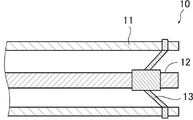
- FIG. 1 is a partial cross-sectional view showing a configuration example of the electrical equipment of the present disclosure. Note that FIG. 1 illustrates a gas-insulated switchgear as an example of gas electrical equipment.
- the electrical equipment 10 shown in FIG. 1 has a grounding tank 11 in which a conductor 12 is arranged. In FIG.
- the conductor 12 is supported by a support member 13 in a state of being insulated from the grounding tank 11.
- the grounding tank 11 is, for example, a confidential container made of metal or the like, a space, or the like.
- a high voltage is applied to the conductor 12. Therefore, the atmosphere around the conductor 12 is filled with an insulating arc-extinguishing gas (not shown).
- the insulated arc extinguishing gas (not shown) is confined in the ground tank 11 by a sealing member (not shown).
- FIG. 2 is a partial cross-sectional view showing a configuration example of a sealing member of the electrical equipment 10 shown in FIG.
- the members 11a and 11b constituting the grounding tank 11 are fixed by bolts 20 and nuts 30, and an O-ring 40 having a circular cross-sectional shape is used as the sealing member.
- the sealing member of the electrical equipment of the present disclosure is not limited to this, and various sealing members used for the purpose of gas sealing, for example, packing, gasket and the like can also be used.
- the cross-sectional shape of the sealing member for example, the cross-sectional shape may be X-shaped, rectangular, or the like.
- the insulating arc extinguishing gas in the present disclosure includes at least one selected from the group consisting of hydrofluoroolefins having 3 or 4 carbon atoms and hydrochlorofluoroolefins having 3 or 4 carbon atoms. These are olefins having a carbon atom-carbon atom double bond. Therefore, it has a short life in the atmosphere. Further, since HFO and HCFO have halogen atoms in their molecular structure, it is presumed that they have high insulating arc extinguishing performance.
- HFO having 3 or 4 carbon atoms examples include 1,1,1,4,4,4-hexafluoro-2-butene (hereinafter, also referred to as HFO-1336mzz), 2,3,3,4,4. , 4-Hexafluoro-1-butene (hereinafter, also referred to as HFO-1336mcyf), 1,3,3,4,4,4-hexafluoro-1-butene (hereinafter, also referred to as HFO-1336ze), Tetra.
- Fluorobutene (hereinafter, also referred to as HFO-1354), 2-fluoropropene (hereinafter, also referred to as HFO-1261yf), 3,3-difluoropropene (hereinafter, also referred to as HFO-1252zf), 1,1,2 -Trifluoropropene (hereinafter, also referred to as HFO-1243yc), 1,2,3-trifluoropropene (hereinafter, also referred to as HFO-1243ye), 2,3,3-trifluoropropene (hereinafter, also referred to as HFO-1243yf).
- 1,1,3-trifluoropropene hereinafter, also referred to as HFO-1243zz
- 1,3,3-trifluoropropene hereinafter, also referred to as HFO-1243ze
- 3,3,3. -Trifluoropropene hereinafter, also referred to as HFO-1243zf
- 1,3,3,3-tetrafluoropropene hereinafter, also referred to as HFO-1234ze
- 1,1,2,3-tetrafluoropropene hereinafter, also referred to as HFO-1234ze
- HFO-1234yc 2,3,3,3-tetrafluoropropene
- HFO-1234yf 2,3,3,3-tetrafluoropropene
- HFO-1234ye 1,2,3,3-tetrafluoropropene
- HFO-1234zc 1,1,3,3-tetrafluoropropene
- HFO-1225ye 1,1,3,3-pentafluoropropene
- HFO-1225yc 1,2,3,3-pentafluoropropene
- HFO-1225zc 1,1,3,3,3-pentafluoropropene
- HFO-1225zc 1,1,3,3,3-pentafluoropropene
- HFO-1225zc 1,1,3,3,3-pentafluoropropene
- HFO-1225zc 1,1,3,3,3-pentafluoropropene
- the isomerization reaction of the HFO may proceed when the electrical equipment 10 is used. If the progress of the isomerization reaction of HFO can be suppressed, the insulating arc extinguishing performance is likely to be maintained, and the safety of the electrical equipment tends to be excellent. For example, the increase in the boiling point of the HFO due to isomerization is suppressed, and the increase in the condensation temperature is suppressed, so that the decrease in the insulation arc extinguishing performance due to liquefaction in the grounding tank 11 is suppressed.
- HFO-1336mzz has a stereoisomer
- the boiling point of the Z isomer of HFO-1336mzz (hereinafter, also referred to as HFO-1336mzz (Z)) is 33 ° C.
- the boiling point of the E isomer (hereinafter, also referred to as HFO-1336mzz (E)) is 7.5 ° C.
- a mixture of HFO-1336mzz (Z) and HFO-1336mzz (E) can be obtained by a known production method, and both can be separated by distillation.
- HFO-1336mzz is used as the insulating arc extinguishing gas
- only one of the Z isomer and the E isomer may be used, or a mixture containing the Z isomer and the E isomer may be used.
- HFO-1336 mzz (E) having a higher boiling point is preferable because it is difficult to liquefy in the ground tank 11.
- a mixture containing Z isomers and E isomers it is preferable to use an isomer mixture having a high proportion of HFO-1336 mzz (E) in consideration of suppression of liquefaction.
- the mass ratio (E / Z ratio) represented by HFO-1336mzz (E) /HFO-1336mzz (Z) is the total mass of HFO-1336mzz filled as an insulating arc extinguishing gas. It is preferably 99/1 to 50/50.
- HFO-1336mzz can also be prepared by contacting CF 3 -CHCl 2 with copper in the presence of an amide solvent and 2,2'-bipyridine, as disclosed in US Pat. No. 8,436,216. ..
- HFO-1336mzz (1) in the presence of a catalyst containing ruthenium, CCl 3 -CF 3 is brought into contact with hydrogen to 1316mxx (2,3-dichloro-1,1,1,4,4,4-). Hexafluoro-2-butene) is produced; (2) E- or Z-1326mxz (1,) by contacting 1316mxx with hydrogen in the presence of a catalyst containing copper, nickel, copper-nickel, or copper-palladium. 1,1,4,4,4-hexafluoro-2-chloro-2-butene); (3) in the presence of a quaternary alkylammonium salt, 1326mxz is contacted with an aqueous solution of alkali metal hydroxide. , Hexafluoro-2-butin, provided; (4) can be prepared by contacting hexafluoro-2-butin with hydrogen and a catalyst, which is disclosed in WO 2015/120250. That's right.
- the HCFO having 3 or 4 carbon atoms includes 1-chloro-2,3,3,3-tetrafluoropropene (hereinafter, also referred to as HCFO-1224yd) and 1-chloro-3,3,3-trifluoro.
- Propen hereinafter, also referred to as HCFO-1233zd
- 2-chloro-1,1,3-trifluoropropene hereinafter, also referred to as HCFO-1233xc
- 2-chloro-1,3,3-trifluoropropene hereinafter, also referred to as HCFO-1233xc
- HCFO-1233xe 2-chloro-3,3,3-trifluoropropene
- HCFO-1233xf 2-chloro-3,3,3-trifluoropropene
- 1-chloro-1,2,3-trifluoropropene hereinafter, also referred to as trifluoropropene
- HCFO-1233yb 3-chloro-1,1,2-trifluoropropene
- HCFO-1233yc 1-chloro-2,3,3-trifluoropropene
- 1233yd also referred to as 1233yd
- HCFO-1233ye 3-chloro-1,2,3-trifluoropropene
- HCFO-1233yf 3-chloro-2,3,3-trifluoropropene
- HCFO-1233zb 1-Chloro-1,3,3-trifluoropropene
- HCFO-1233zc 3-chloro-1,1,3-trifluoropropene
- HCFO-1233ze 3-Chloro-1,3,3-trifluoropropene
- 1,2-dichloro-3,3,3-trifluoropropene HCFO-1223xd
- 2,3 -Dichloro-3,3-difluoropropene hereinafter, also referred to as HCFO-1232xf
- 2,3,3-trichloro-3-fluoropropene HCFO-1231xf
- 2-chloro-1,1,3,3- Tetrafluoropropene hereinafter, also referred to as HCFO-1224xc
- 2-chloro-1,3,3,3-tetrafluoropropene hereinafter, also referred to as HCFO-1224xe
- 1,2,3-trichloro-3 examples thereof include 3-difluoropropene (hereinafter, also referred to as HCFO-1222xd) and 1-chloro-3,3,3-trifluoro-1-propine (
- HCFO-1224yd tends to suppress the progress of the isomerization reaction when the electrical equipment 10 is used.
- HCFO-1224yd is known to have a stereoisomer, and the boiling point of the Z isomer of HCFO-1224yd (hereinafter, also referred to as HCFO-1224yd (Z)) is 15 ° C., and that of HCFO-1224yd.
- the boiling point of the E isomer (hereinafter, also referred to as HCFO-1224yd (E)) is 17 ° C.
- a mixture of HCFO-1224yd (Z) and HCFO-1224yd (E) can be obtained by a known production method, and both can be separated by distillation.
- HCFO-1224yd When HCFO-1224yd is used as the insulating arc extinguishing gas, only one of the Z isomer and the E isomer may be used, or a mixture containing the Z isomer and the E isomer may be used. When only one of the Z isomer and the E isomer is used, HCFO-1224yd (Z) is preferable because it is difficult to liquefy in the ground tank 11 in consideration of the boiling point. When using a mixture containing Z isomers and E isomers, it is preferable to use an isomer mixture having a high proportion of HCFO-1224yd (Z) in consideration of suppression of liquefaction and productivity.
- the mass ratio (Z / E ratio) represented by HCFO-1224yd (Z) / HCFO-1224yd (E) is the total mass of HCFO-1224yd to be filled as an insulating arc extinguishing gas. It is preferably 99/1 to 50/50.
- Examples of the method for producing HCFO-1224yd include (1) a method of dehydrochlorinating 1,2-dichloro-2,3,3,3-tetrafluoropropane (hereinafter, also referred to as HCFC-234bb). And (2) a method of hydrogen-reducing 1,1-dichloro-2,3,3,3-tetrafluoropropene (hereinafter, also referred to as CFO-1214ya) can be mentioned.
- HCFC-234bb a method of dehydrochlorinating 1,2-dichloro-2,3,3,3-tetrafluoropropane
- CFO-1214ya hydrogen-reducing 1,1-dichloro-2,3,3,3-tetrafluoropropene
- HCFC-234bb is brought into contact with a base dissolved in a solvent (that is, a base in a solution state) to carry out a dehydrochlorination reaction of HCFC-234bb.
- HCFC-234bb can be produced, for example, by reacting 2,3,3,3-tetrafluoropropene (hereinafter, also referred to as HFO-1234yf) with chlorine in a solvent.
- CFO-1214ya is, for example, using 3,3-dichloro-1,1,1,2,2-pentafluoropropane or the like as a raw material, in an alkaline aqueous solution in the presence of a phase transfer catalyst, or chromium, iron, copper, activated carbon.
- a method of producing by subjecting to a defluorinated hydrogen reaction in a gas phase reaction in the presence of a catalyst such as.
- the insulating arc extinguishing gas in the present disclosure preferably comprises at least one selected from the group consisting of HCFO-1224yd and HFO-1336mzz, preferably HCFO-1224yd (Z), HFO-1336mzz (Z), and HFO-1336mzz. It is more preferred to include at least one selected from the group consisting of (E), and even more preferably to include at least one selected from the group consisting of HCFO-1224yd (Z) and HFO-1336mzz (E).
- the insulating arc extinguishing gas in the present disclosure may further contain at least one diluted gas selected from the group consisting of He, Ar, CO 2 , N 2 , O 2, N 2 O, CH 4 , and air. ..
- the insulating arc extinguishing gas contains the above diluted gas, the volume ratio of the total amount of HFO and HCFO to the total amount of HFO and HCFO in the total amount of the diluted gas is because HFO and HCFO are present only in the gas phase state.
- 70% by volume or less is preferable, 60% by volume or less is more preferable, 50% by volume or less is further preferable, 40% by volume or less is further preferable, 30% by volume or less is further preferable, and 25.
- By volume or less is further preferable, 20% by volume or less is further preferable, 15% by volume or less is further preferable, 10% by volume or less is further preferable, and 5% by volume or less is further preferable.
- the volume ratio of the total amount of HFO and HCFO to the total amount of HFO and HCFO in the total amount of the diluted gas is preferably 1% by volume or more, more preferably 2% by volume or more, and 3 More preferably, by volume or more.
- the sealing member in the present disclosure includes ethylene propylene rubber (hereinafter, also referred to as EPDM), isobutylene / isoprene rubber (hereinafter, also referred to as IIR), chloroprene rubber (hereinafter, also referred to as CR), and natural rubber (hereinafter, NR). Also referred to as), nitrile rubber (hereinafter, also referred to as NBR), hydride nitrile rubber (hereinafter, also referred to as HNBR), urethane rubber (hereinafter, also referred to as UR), chlorosulfonated polyethylene rubber (hereinafter, also referred to as Hyparon (hereinafter, also referred to as Hyparon)).
- EPDM ethylene propylene rubber
- IIR isobutylene / isoprene rubber
- CR chloroprene rubber
- NR natural rubber
- NBR nitrile rubber
- HNBR hydride nitrile rubber
- UR
- CSM Registered trademark rubber
- FKM vinylidene fluoride-based fluorororubber
- FFKM tetrafluoroethylene-perfluorovinyl ether-based rubber
- PTFE polytetrafluoroethylene
- HFO with 3 or 4 carbon atoms and HCFO with 3 or 4 carbon atoms have a small GWP.
- the reaction between the HFO having 3 or 4 carbon atoms or the HCFO having 3 or 4 carbon atoms and the sealing member is suppressed.
- the occurrence of swelling, shrinkage, elution, etc. of the sealing member can be suppressed.
- leakage of the insulating arc extinguishing gas from the grounding tank 11 is suppressed.
- a diluting gas such as He, Ar, CO 2 , O 2 , N 2, N 2 O, CH 4 and air is used in combination.
- a diluting gas such as He, Ar, CO 2 , O 2 , N 2, N 2 O, CH 4 and air is used in combination.
- the insulating arc extinguishing gas leaks or is sealed from the grounding tank 11 by using the above-mentioned sealing member. The influence on the members can be reduced.
- the sealing member in the present disclosure preferably contains at least one selected from the group consisting of HNBR, FKM, FFKM, and PTFE.
- the electrical equipment may be equipped with various equipment electrically in series or in parallel along an electric circuit (electric circuit) including a conductor.
- Examples of the above-mentioned equipment include switches, circuit breakers, disconnectors, etc. for cutting the electric circuit, transformers, resistors, reactors, capacitors, etc. for changing the voltage of the electric circuit.
- an insulating arc extinguishing gas filled inside the grounding tank may be used.
- Other insulating arc extinguishing gas may be used.
- Other insulating arc extinguishing gases include, for example, hydrogen, helium, SF 6 , and a mixed gas thereof.
- a solid insulator, an insulating oil, a gel-like insulator or the like may be used for the internal or external insulation of the above equipment.
- the inside or outside of the above equipment may be insulated by a vacuum state.
- the solid insulator include an insulating resin material and the like.
- the insulating resin material include thermoplastic resins and thermosetting resins.
- the thermoplastic resin include vinyl chloride-based, polyester-based, and nylon-based resins.
- the thermosetting resin include epoxy-based and urethane-based resins.
- the insulating oil include mineral oil, vegetable oil, animal oil, and fluorine-based oil.
- the filling facility of the present disclosure is a facility for filling the ground tank of the electrical equipment of the present disclosure with insulating arc extinguishing gas, and the insulating arc extinguishing gas is confined in the filling facility by a sealing member, and the insulating arc extinguishing is performed.
- the gas comprises at least one selected from the group consisting of hydrofluoroolefins having 3 or 4 carbon atoms and hydrochlorofluoroolefins having 3 or 4 carbon atoms, and the sealing member is an ethylene propylene rubber.
- Isobutylene / isoprene rubber Isobutylene / isoprene rubber, chloroprene rubber, natural rubber, nitrile rubber, hydronitrile nitrile rubber, urethane rubber, Hyparon® rubber, vinylidene fluoride-based fluororubber, tetrafluoroethylene-perfluorovinyl ether-based rubber, and polytetra. Includes at least one selected from the group consisting of fluoroethylenes.
- the filling equipment includes a container that houses the insulated arc extinguishing gas, a heating facility that heats the container that contains the insulated arc extinguishing gas, a pump that pressurizes the insulated arc extinguishing gas, and pipes and hoses that connect to the tank of the electrical equipment. It may have an on-off valve, a vacuum pump for exhausting the inside of electrical equipment, an adsorbent for water and decomposition gas, and the like.
- the filling equipment of the present disclosure uses the above-mentioned sealing member to confine the insulating arc extinguishing gas.
- Insulated arc extinguishing gas in filling equipment is synonymous with that explained in electrical equipment. Further, the sealing member in the filling equipment has the same meaning as that described in the electrical equipment.
- the storage facility of the present disclosure is a facility for storing the insulating arc-extinguishing gas to be filled in the ground tank of the electrical equipment of the present disclosure, and the edge-extinguishing gas is confined in the storage facility by a sealing member and is insulated.
- the extinguishing gas comprises at least one selected from the group consisting of hydrofluoroolefins having 3 or 4 carbon atoms and hydrochlorofluoroolefins having 3 or 4 carbon atoms, and the sealing member is ethylene.
- Propylene rubber isobutylene / isoprene rubber, chloroprene rubber, natural rubber, nitrile rubber, hydronitrile nitrile rubber, urethane rubber, Hyparon® rubber, vinylidene fluoride-based fluororubber, tetrafluoroethylene-perfluorovinyl ether-based rubber, and Includes at least one selected from the group consisting of polytetrafluoroethylene.
- the storage equipment of the present disclosure may have a tank for storing the insulated arc extinguishing gas, an on-off valve, and the like.
- the storage equipment of the present disclosure uses the above-mentioned sealing member to confine the insulating arc extinguishing gas.
- Insulated arc extinguishing gas in storage equipment is synonymous with that explained in electrical equipment. Further, the sealing member in the storage equipment has the same meaning as that described in the electrical equipment.
- Examples 1 to 3, 5, 6, 8, 9, 11 to 17, 19, 20, 22, 23, 25 to 32 are examples, and examples 4, 7, 10, 18, 21, 24 are comparative examples. be. However, the embodiments of the present disclosure are not limited to these examples.
- the gas permeability (GTR) was calculated using the following formula. HCFO-1224yd (Z), HFO-1336mzz (Z), or HFO-1336mzz (E) was used as the test gas. FKM, FFKM, IIR, vinyl methyl silicone rubber (VMQ), EPDM, CR, acrylic rubber (ACM), NR, NBR, styrene butadiene rubber (SBR), HNBR, UR, CSM, or PTFE were used as test pieces.
- the gas permeability (GTR) is the unit area, unit time, and the number of moles per unit partial pressure between both sides of the test piece, which is expressed by the following formula.
- V c Gas permeability [mol / ( m2 ⁇ s ⁇ Pa)]
- V c Volume of low pressure side cell [m 3 ]
- R Gas constant 8.31 [m 3 ⁇ Pa / (K ⁇ mol)]
- T Test temperature
- Pu Pressure difference between the high pressure side and the low pressure side of the test gas
- A Gas permeation area [m 2 ]
- dp / dt Pressure change of low pressure side cell per unit time [Pa / s]
- V c , T, Pu and A were set to the following fixed values.
- V c 2.5 ⁇ 10-6 [m 3 ]
- T 323 ⁇ 2
- Pu 100,000 [Pa]
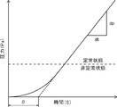
- FIG. 4 is a graph showing the relationship between the execution time of the gas permeation test and the pressure of the low pressure side cell.
- the pressure change of the low pressure side cell per unit time increases after the start of the gas permeation test, and becomes a steady state after a specific time elapses.
- the above-mentioned dp / dt is a numerical value in a steady state.
- the intersection of the dp / dt straight line and the x-axis is displayed as the time ⁇ .
- the gas permeability coefficient Q was calculated from the GTR calculated in the above procedure.
- the gas permeability coefficient Q is the unit thickness, unit area, unit time, and number of moles per unit partial pressure between both sides of the test piece of the test gas passing through the test, and is expressed by the following formula.
- Q GTR x h
- Q Gas permeability coefficient [mol ⁇ m / ( m2 ⁇ s ⁇ Pa)]
- GTR Gas permeability [mol / ( m2 ⁇ s ⁇ Pa)]
- h Average thickness of test piece [m] The average thickness of the test piece was 2.0 ⁇ 10 -3 [m].
- the gas permeability coefficient QR calculated using SF 6 as the test gas and vinyl methyl silicone rubber (VMQ ) as the test piece was used as reference data, and the relationship between the obtained gas permeability coefficient Q and QR was used.
- the gas permeability of the test gas in the test piece was evaluated according to the following criteria.
- test piece 25 mm ⁇ 30 mm ⁇ 2 mm
- the test piece was immersed in 60 g of the liquefied test gas at 50 ° C. ⁇ 120 hours, and the volume change of the test piece was evaluated according to the following criteria.
- D Negative volume change (contraction) occurs at 5% or more, or positive volume change (swelling) occurs 100% Occurs with the above
- the determination result was B or higher.
- the determination result was A.
- Example 4 in which VMQ was used as the test piece, the result of both the gas permeation test and the material influence test was D, and the determination result was D.
- Example 18 in which VMQ was used as the test piece, the result of the material influence test was A, but the result of the gas permeation test was D, and the judgment result was D.
- Example 7 in which ACM was used as the test piece, the result of the gas permeation test was B, but the result of the material influence test was D, and the judgment result was D.
- Example 21 in which ACM was used as the test piece, the result of the gas permeation test was C, but the result of the material influence test was D, and the judgment result was D.
- the insulating arc extinguishing gas of the grounding tank of the electric equipment is selected from the group consisting of hydrofluoroolefins having 3 or 4 carbon atoms and hydrochlorofluoroolefins having 3 or 4 carbon atoms. If at least one is used and FKM, FFKM, IIR, EPDM, CR, NR, NBR, HNBR, UR, CSM, or PTFE is used as the sealing member, the insulating arc extinguishing gas from the ground tank can be used. It is considered that leakage and the influence on the sealing member are reduced. If FKM, FFKM, HNBR, or PTFE is used as the sealing member, it is considered that the leakage of the insulating arc extinguishing gas from the grounding tank and the influence on the sealing member are further reduced.
Landscapes
- Engineering & Computer Science (AREA)
- Power Engineering (AREA)
- Manufacturing & Machinery (AREA)
- Gas-Insulated Switchgears (AREA)
- Organic Low-Molecular-Weight Compounds And Preparation Thereof (AREA)
- Compositions Of Macromolecular Compounds (AREA)
- Organic Insulating Materials (AREA)
Abstract
Description
従来、このような電気設備に使用される絶縁消弧ガスとして、例えばSF6が知られていた。しかし、SF6は、絶縁消弧性能が高いが、地球温暖化係数(GWP)が大きい。このため、環境負荷低減の観点から、SF6を代替する絶縁消弧ガスとして、ハイドロフルオロオレフィン(以下、HFOともいう。)やハイドロクロロフルオロオレフィン(以下、HCFOともいう。)の使用が検討されている。特許文献1には、HFOを含む絶縁ガスが絶縁消弧に有用であるとされている。 Electrical equipment such as gas-insulated switchgear has a grounding tank in which a conductor is arranged. The insulating arc extinguishing performance is ensured by filling the atmosphere around the conductor in the grounding tank with the insulating arc extinguishing gas.
Conventionally, for example, SF 6 has been known as an insulating arc extinguishing gas used in such electric equipment. However, although SF 6 has high insulation and extinguishing performance, it has a large global warming potential (GWP). Therefore, from the viewpoint of reducing the environmental load, the use of hydrofluoroolefin (hereinafter, also referred to as HFO) or hydrochlorofluoroolefin (hereinafter, also referred to as HCFO) is considered as an insulating arc-extinguishing gas that replaces SF 6 . ing. Patent Document 1 states that an insulating gas containing HFO is useful for insulating arc extinguishing.
また、沸点が高いHFOやHCFOは、使用環境下での凝縮や液化を抑える観点から、He、Ar、CO2、O2、N2、N2O、CH4および空気等の希釈ガスと混合して使用する場合がある。絶縁消弧ガスがOリング等の封止部材に何らかの影響を及ぼすと、接地タンクから絶縁消弧ガスや希釈ガスが漏洩する可能性がある。そうなると、混合ガスの組成が変化し、混合ガスの凝縮温度の上昇や絶縁消弧性能の低下が生じるおそれがある。 The insulated arc extinguishing gas is confined in the grounding tank by a sealing member such as an O-ring. Depending on the type of insulating arc extinguishing gas, it may have some effect on the sealing member such as the O-ring. As a result, the insulating arc extinguishing gas may leak from the ground tank. In that case, the pressure of the insulating arc extinguishing gas in the grounding tank may decrease, and the insulating arc extinguishing performance may deteriorate.
In addition, HFO and HCFO having a high boiling point are mixed with diluted gases such as He, Ar, CO 2 , O 2 , N 2, N 2 O, CH 4 and air from the viewpoint of suppressing condensation and liquefaction in the usage environment. May be used. If the insulated arc extinguishing gas has any effect on the sealing member such as the O-ring, the insulated arc extinguishing gas or the diluted gas may leak from the grounding tank. In that case, the composition of the mixed gas may change, resulting in an increase in the condensation temperature of the mixed gas and a decrease in the insulation arc extinguishing performance.
また、本開示の一実施形態は、上記電気設備の接地タンクに絶縁消弧ガスを充填するための充填設備、および上記電気設備の接地タンクに充填する絶縁消弧ガスを貯蔵する貯蔵設備の提供も課題とする。 One embodiment of the present disclosure is made in view of the above problems, and an object of the present invention is to provide electrical equipment in which leakage of insulating arc extinguishing gas from a grounding tank and influence on a sealing member are reduced.
Further, one embodiment of the present disclosure provides a filling facility for filling the grounding tank of the electrical equipment with an insulated arc-extinguishing gas, and a storage facility for storing the insulated arc-extinguishing gas filled in the grounding tank of the electrical equipment. Is also an issue.
[1] 内部に導体が配置された接地タンクを有し、
上記接地タンク内が絶縁消弧ガスで満たされており、
上記導体の周りの雰囲気が絶縁消弧ガスで満たされており、
上記絶縁消弧ガスが封止部材により上記接地タンク内に閉じ込められており、
上記絶縁消弧ガスが、炭素数3または炭素数4のハイドロフルオロオレフィン、および、炭素数3または炭素数4のハイドロクロロフルオロオレフィンからなる群から選択される少なくとも1つを含み、
上記封止部材が、エチレンプロピレンゴム、イソブチレン・イソプレンゴム、クロロプレンゴム、天然ゴム、ニトリルゴム、水素化ニトリルゴム、ウレタンゴム、クロロスルホン化ポリエチレンゴム、フッ化ビニリデン系フッ素ゴム、テトラフルオロエチレン-パーフルオロビニルエーテル系ゴム、およびポリテトラフルオロエチレンからなる群から選択される少なくとも1つを含む、電気設備。
[2] 上記絶縁消弧ガスが、1-クロロ-2,3,3,3-テトラフルオロプロペン、および1,1,1,4,4,4-ヘキサフルオロ-2-ブテンからなる群から選択される少なくとも1つを含む、[1]に記載の電気設備。
[3] 上記絶縁消弧ガスが、さらにHe、Ar、CO2、N2、O2、N2O、CH4、および空気からなる群から選択される少なくとも1つの希釈ガスを含む、[1]または[2]に記載の電気設備。
[4] 前記封止部材が、水素化ニトリルゴム、フッ化ビニリデン系フッ素ゴム、テトラフルオロエチレン-パーフルオロビニルエーテル系ゴム、およびポリテトラフルオロエチレンからなる群から選択される少なくとも1つを含む、[1]~[3]のいずれか1項に記載の電気設備。
[5] [1]~[4]のいずれかに記載の電気設備の接地タンクに絶縁消弧ガスを充填するための充填設備であって、
上記絶縁消弧ガスが封止部材により上記充填設備内に閉じ込められており、
上記絶縁消弧ガスが、炭素数3または炭素数4のハイドロフルオロオレフィン、および、炭素数3または炭素数4のハイドロクロロフルオロオレフィンからなる群から選択される少なくとも1つを含み、
上記封止部材が、エチレンプロピレンゴム、イソブチレン・イソプレンゴム、クロロプレンゴム、天然ゴム、ニトリルゴム、水素化ニトリルゴム、ウレタンゴム、クロロスルホン化ポリエチレンゴム、フッ化ビニリデン系フッ素ゴム、テトラフルオロエチレン-パーフルオロビニルエーテル系ゴム、およびポリテトラフルオロエチレンからなる群から選択される少なくとも1つを含む、充填設備。
[6] 上記絶縁消弧ガスが、1-クロロ-2,3,3,3-テトラフルオロプロペン、および1,1,1,4,4,4-ヘキサフルオロ-2-ブテンからなる群から選択される少なくとも1つを含む、[5]に記載の充填設備。
[7] 上記絶縁消弧ガスが、さらにHe、Ar、CO2、N2、O2、N2O、CH4、および空気からなる群から選択される少なくとも1つの希釈ガスを含む、[5]または[6]に記載の充填設備。
[8] 前記封止部材が、水素化ニトリルゴム、フッ化ビニリデン系フッ素ゴム、テトラフルオロエチレン-パーフルオロビニルエーテル系ゴム、およびポリテトラフルオロエチレンからなる群から選択される少なくとも1つを含む、[5]~[7]のいずれか1項に記載の充填設備。
[9] [1]~[4]のいずれかに記載の電気設備の接地タンクに充填する絶縁消弧ガスを貯蔵する貯蔵設備であって、
上記絶縁消弧ガスが封止部材により上記貯蔵設備内に閉じ込められており、
上記絶縁消弧ガスが、炭素数3または炭素数4のハイドロフルオロオレフィン、および、炭素数3または炭素数4のハイドロクロロフルオロオレフィンからなる群から選択される少なくとも1つを含み、
上記封止部材が、エチレンプロピレンゴム、イソブチレン・イソプレンゴム、クロロプレンゴム、天然ゴム、ニトリルゴム、水素化ニトリルゴム、ウレタンゴム、クロロスルホン化ポリエチレンゴム、フッ化ビニリデン系フッ素ゴム、テトラフルオロエチレン-パーフルオロビニルエーテル系ゴム、およびポリテトラフルオロエチレンからなる群から選択される少なくとも1つを含む、貯蔵設備。
[10] 上記絶縁消弧ガスが、1-クロロ-2,3,3,3-テトラフルオロプロペン、および1,1,1,4,4,4-ヘキサフルオロ-2-ブテンからなる群から選択される少なくとも1つを含む、[9]に記載の貯蔵設備。
[11] 上記絶縁消弧ガスが、さらにHe、Ar、CO2、N2、O2、N2O、CH4、および空気からなる群から選択される少なくとも1つの希釈ガスを含む、[9]または[10]に記載の貯蔵設備。
[12] 前記封止部材が、水素化ニトリルゴム、フッ化ビニリデン系フッ素ゴム、テトラフルオロエチレン-パーフルオロビニルエーテル系ゴム、およびポリテトラフルオロエチレンからなる群から選択される少なくとも1つを含む、[9]~[11]のいずれか1項に記載の貯蔵設備。 The present disclosure includes the following embodiments [1] to [12].
[1] It has a grounding tank in which a conductor is arranged.
The inside of the above grounding tank is filled with insulating arc extinguishing gas,
The atmosphere around the conductor is filled with insulating arc extinguishing gas,
The insulating arc extinguishing gas is confined in the grounding tank by a sealing member.
The insulating arc extinguishing gas contains at least one selected from the group consisting of hydrofluoroolefins having 3 or 4 carbon atoms and hydrochlorofluoroolefins having 3 or 4 carbon atoms.
The sealing member is ethylene propylene rubber, isobutylene / isoprene rubber, chloroprene rubber, natural rubber, nitrile rubber, hydride nitrile rubber, urethane rubber, chlorosulfonated polyethylene rubber, vinylidene fluoride-based fluororubber, tetrafluoroethylene-per. Electrical equipment comprising at least one selected from the group consisting of fluorovinyl ether rubber and polytetrafluoroethylene.
[2] The insulating arc extinguishing gas is selected from the group consisting of 1-chloro-2,3,3,3-tetrafluoropropene and 1,1,1,4,4,4-hexafluoro-2-butene. The electrical equipment according to [1], which comprises at least one.
[3] The insulating arc extinguishing gas further contains at least one diluted gas selected from the group consisting of He, Ar, CO 2 , N 2 , O 2, N 2 O, CH 4 , and air [1]. ] Or the electrical equipment according to [2].
[4] The sealing member comprises at least one selected from the group consisting of hydride nitrile rubber, vinylidene fluoride-based fluororubber, tetrafluoroethylene-perfluorovinyl ether-based rubber, and polytetrafluoroethylene. 1] The electrical equipment according to any one of [3].
[5] A filling facility for filling the grounding tank of the electrical equipment according to any one of [1] to [4] with an insulating arc extinguishing gas.
The insulating arc extinguishing gas is confined in the filling equipment by a sealing member.
The insulating arc extinguishing gas contains at least one selected from the group consisting of hydrofluoroolefins having 3 or 4 carbon atoms and hydrochlorofluoroolefins having 3 or 4 carbon atoms.
The sealing member is ethylene propylene rubber, isobutylene / isoprene rubber, chloroprene rubber, natural rubber, nitrile rubber, hydride nitrile rubber, urethane rubber, chlorosulfonated polyethylene rubber, vinylidene fluoride-based fluororubber, tetrafluoroethylene-per. A filling facility comprising at least one selected from the group consisting of fluorovinyl ether rubber and polytetrafluoroethylene.
[6] The insulating arc extinguishing gas is selected from the group consisting of 1-chloro-2,3,3,3-tetrafluoropropene and 1,1,1,4,4,4-hexafluoro-2-butene. The filling facility according to [5], comprising at least one to be made.
[7] The insulating arc extinguishing gas further contains at least one diluted gas selected from the group consisting of He, Ar, CO 2 , N 2 , O 2, N 2 O, CH 4 , and air [5]. ] Or the filling equipment according to [6].
[8] The sealing member comprises at least one selected from the group consisting of hydride nitrile rubber, vinylidene fluoride-based fluororubber, tetrafluoroethylene-perfluorovinyl ether-based rubber, and polytetrafluoroethylene. 5] The filling facility according to any one of [7].
[9] A storage facility for storing an insulated arc extinguishing gas to be filled in the grounding tank of the electrical facility according to any one of [1] to [4].
The insulating arc extinguishing gas is confined in the storage facility by a sealing member.
The insulating arc extinguishing gas contains at least one selected from the group consisting of hydrofluoroolefins having 3 or 4 carbon atoms and hydrochlorofluoroolefins having 3 or 4 carbon atoms.
The sealing member is ethylene propylene rubber, isobutylene / isoprene rubber, chloroprene rubber, natural rubber, nitrile rubber, hydride nitrile rubber, urethane rubber, chlorosulfonated polyethylene rubber, vinylidene fluoride-based fluororubber, tetrafluoroethylene-per. A storage facility comprising at least one selected from the group consisting of fluorovinyl ether rubber and polytetrafluoroethylene.
[10] The insulating arc extinguishing gas is selected from the group consisting of 1-chloro-2,3,3,3-tetrafluoropropene and 1,1,1,4,4,4-hexafluoro-2-butene. The storage facility according to [9], which comprises at least one.
[11] The insulating arc extinguishing gas further contains at least one diluted gas selected from the group consisting of He, Ar, CO 2 , N 2 , O 2, N 2 O, CH 4 , and air [9]. ] Or the storage facility according to [10].
[12] The sealing member comprises at least one selected from the group consisting of hydride nitrile rubber, vinylidene fluoride-based fluororubber, tetrafluoroethylene-perfluorovinyl ether-based rubber, and polytetrafluoroethylene. 9] The storage facility according to any one of [11].
また、本開示によれば、上記電気設備の接地タンクに絶縁消弧ガスを充填するための充填設備、および上記電気設備の接地タンクに充填する絶縁消弧ガスを貯蔵する貯蔵設備を提供できる。 According to the present disclosure, it is possible to provide electrical equipment in which leakage of insulating arc extinguishing gas from a grounding tank and influence on a sealing member are reduced.
Further, according to the present disclosure, it is possible to provide a filling facility for filling the ground tank of the electric equipment with an insulated arc extinguishing gas and a storage facility for storing the insulated arc extinguishing gas filled in the ground tank of the electric facility.
(電気設備)
本開示の電気設備は、内部に導体が配置された接地タンクを有し、接地タンク内の導体の周囲の雰囲気が絶縁消弧ガスで満たされている。
図1は、本開示の電気設備の構成例を示した部分断面図である。なお、図1では、ガス電気設備の一例としてガス絶縁開閉装置が図示されている。
図1に示す電気設備10は、内部に導体12が配置された接地タンク11を有する。
図1において、導体12は、支持部材13によって接地タンク11と絶縁された状態で支持されている。接地タンク11は、例えば、金属等からなる機密性の容器、空間等である。導体12には、高電圧が印加される。そのため、導体12の周りの雰囲気は、絶縁消弧ガス(図示せず)で満たされている。絶縁消弧ガス(図示せず)は、封止部材(図示せず)により接地タンク11内に閉じ込められている。 Hereinafter, embodiments of the present disclosure will be described with reference to the drawings. However, the embodiments of the present disclosure are not limited to the embodiments described in the drawings.
(electrical equipment)
The electrical equipment of the present disclosure has a grounding tank in which a conductor is arranged, and the atmosphere around the conductor in the grounding tank is filled with an insulating arc extinguishing gas.
FIG. 1 is a partial cross-sectional view showing a configuration example of the electrical equipment of the present disclosure. Note that FIG. 1 illustrates a gas-insulated switchgear as an example of gas electrical equipment.
The
In FIG. 1, the
但し、本開示の電気設備の封止部材はこれに限定されず、ガスシール目的で使用される各種封止部材、例えば、パッキン、ガスケット等も使用できる。また、封止部材の断面形状についても、例えば、断面形状がX形、長方形等であってもよい。 FIG. 2 is a partial cross-sectional view showing a configuration example of a sealing member of the
However, the sealing member of the electrical equipment of the present disclosure is not limited to this, and various sealing members used for the purpose of gas sealing, for example, packing, gasket and the like can also be used. Further, regarding the cross-sectional shape of the sealing member, for example, the cross-sectional shape may be X-shaped, rectangular, or the like.
HFO-1336mzzは、電気設備10の使用時に異性化反応が進行しにくいため、絶縁消弧性能が維持されやすく、電気設備の安全性に優れる傾向にある。 When the
Since the isomerization reaction of HFO-1336mzz does not easily proceed when the
Z異性体およびE異性体の一方のみを使用する場合、沸点がより高いHFO-1336mzz(E)の方が接地タンク11内で液化しにくく好ましい。
Z異性体およびE異性体を含む混合物を使用する場合、液化の抑制を考慮するとHFO-1336mzz(E)の割合が高い異性体混合物を使用することが好ましい。異性体混合物を使用する場合、絶縁消弧ガスとして充填するHFO-1336mzzの全質量において、HFO-1336mzz(E)/HFO-1336mzz(Z)で表される質量比(E/Z比)は、99/1~50/50が好ましい。 When HFO-1336mzz is used as the insulating arc extinguishing gas, only one of the Z isomer and the E isomer may be used, or a mixture containing the Z isomer and the E isomer may be used.
When only one of the Z isomer and the E isomer is used, HFO-1336 mzz (E) having a higher boiling point is preferable because it is difficult to liquefy in the
When a mixture containing Z isomers and E isomers is used, it is preferable to use an isomer mixture having a high proportion of HFO-1336 mzz (E) in consideration of suppression of liquefaction. When an isomer mixture is used, the mass ratio (E / Z ratio) represented by HFO-1336mzz (E) /HFO-1336mzz (Z) is the total mass of HFO-1336mzz filled as an insulating arc extinguishing gas. It is preferably 99/1 to 50/50.
Z異性体およびE異性体の一方のみを使用する場合、沸点を考慮するとHCFO-1224yd(Z)の方が接地タンク11内で液化しにくく好ましい。
Z異性体およびE異性体を含む混合物を使用する場合、液化の抑制および生産性を考慮するとHCFO-1224yd(Z)の割合が高い異性体混合物を使用することが好ましい。異性体混合物を使用する場合、絶縁消弧ガスとして充填するHCFO-1224ydの全質量において、HCFO-1224yd(Z)/HCFO-1224yd(E)で表される質量比(Z/E比)は、99/1~50/50が好ましい。 When HCFO-1224yd is used as the insulating arc extinguishing gas, only one of the Z isomer and the E isomer may be used, or a mixture containing the Z isomer and the E isomer may be used.
When only one of the Z isomer and the E isomer is used, HCFO-1224yd (Z) is preferable because it is difficult to liquefy in the
When using a mixture containing Z isomers and E isomers, it is preferable to use an isomer mixture having a high proportion of HCFO-1224yd (Z) in consideration of suppression of liquefaction and productivity. When an isomer mixture is used, the mass ratio (Z / E ratio) represented by HCFO-1224yd (Z) / HCFO-1224yd (E) is the total mass of HCFO-1224yd to be filled as an insulating arc extinguishing gas. It is preferably 99/1 to 50/50.
以下、それぞれの方法について詳述する。 Examples of the method for producing HCFO-1224yd include (1) a method of dehydrochlorinating 1,2-dichloro-2,3,3,3-tetrafluoropropane (hereinafter, also referred to as HCFC-234bb). And (2) a method of hydrogen-reducing 1,1-dichloro-2,3,3,3-tetrafluoropropene (hereinafter, also referred to as CFO-1214ya) can be mentioned.
Hereinafter, each method will be described in detail.
HCFC-234bbを液相中で、溶媒に溶解した塩基(すなわち溶液状態の塩基)と接触させ、HCFC-234bbの脱塩化水素反応を行う。なお、HCFC-234bbは、例えば、2,3,3,3-テトラフルオロプロペン(以下、HFO-1234yfともいう。)と塩素を溶媒中で反応させることにより製造できる。 (1) Dehydrochlorination reaction of HCFC-234bb In the liquid phase, HCFC-234bb is brought into contact with a base dissolved in a solvent (that is, a base in a solution state) to carry out a dehydrochlorination reaction of HCFC-234bb. HCFC-234bb can be produced, for example, by reacting 2,3,3,3-tetrafluoropropene (hereinafter, also referred to as HFO-1234yf) with chlorine in a solvent.
CFO-1214yaを触媒存在下、水素を用いて還元することでHFO-1234yfに還元され、その中間体としてHCFO-1224ydが得られる。また、この還元反応においては、HCFO-1224yd以外に多種類の含フッ素化合物が副生する。CFO-1214yaは、例えば、3,3-ジクロロ-1,1,1,2,2-ペンタフルオロプロパン等を原料として、相関移動触媒存在下にアルカリ水溶液で、または、クロム、鉄、銅、活性炭等の触媒存在下での気相反応で、脱フッ化水素反応させて製造する方法が知られている。 (2) Method for reducing CFO-1214ya with hydrogen By reducing CFO-1214ya with hydrogen in the presence of a catalyst, it is reduced to HFO-1234yf, and HCFO-1224yd is obtained as an intermediate thereof. Further, in this reduction reaction, many kinds of fluorine-containing compounds are by-produced in addition to HCFO-1224yd. CFO-1214ya is, for example, using 3,3-dichloro-1,1,1,2,2-pentafluoropropane or the like as a raw material, in an alkaline aqueous solution in the presence of a phase transfer catalyst, or chromium, iron, copper, activated carbon. There is known a method of producing by subjecting to a defluorinated hydrogen reaction in a gas phase reaction in the presence of a catalyst such as.
絶縁消弧ガスが上記の希釈ガスを含む場合、HFOおよびHCFOの総量と、希釈ガスとの合計中のHFOおよびHCFOの総量の体積比率は、HFOおよびHCFOが気相状態のみで存在するために必要な凝縮温度を実現する観点から、70体積%以下が好ましく、60体積%以下がより好ましく、50体積%以下がさらに好ましく、40体積%以下がさらに好ましく、30体積%以下がさらに好ましく、25体積%以下がさらに好ましく、20体積%以下がさらに好ましく、15体積%以下がさらに好ましく、10体積%以下がさらに好ましく、5体積%以下がさらに好ましい。一方、絶縁消弧性能の観点から、HFOおよびHCFOの総量と、希釈ガスとの合計中のHFOおよびHCFOの総量の体積比率は、1体積%以上が好ましく、2体積%以上がより好ましく、3体積%以上がさらに好ましい。 The insulating arc extinguishing gas in the present disclosure may further contain at least one diluted gas selected from the group consisting of He, Ar, CO 2 , N 2 , O 2, N 2 O, CH 4 , and air. ..
When the insulating arc extinguishing gas contains the above diluted gas, the volume ratio of the total amount of HFO and HCFO to the total amount of HFO and HCFO in the total amount of the diluted gas is because HFO and HCFO are present only in the gas phase state. From the viewpoint of achieving the required condensation temperature, 70% by volume or less is preferable, 60% by volume or less is more preferable, 50% by volume or less is further preferable, 40% by volume or less is further preferable, 30% by volume or less is further preferable, and 25. By volume or less is further preferable, 20% by volume or less is further preferable, 15% by volume or less is further preferable, 10% by volume or less is further preferable, and 5% by volume or less is further preferable. On the other hand, from the viewpoint of insulating arc extinguishing performance, the volume ratio of the total amount of HFO and HCFO to the total amount of HFO and HCFO in the total amount of the diluted gas is preferably 1% by volume or more, more preferably 2% by volume or more, and 3 More preferably, by volume or more.
このような開閉器、遮断器、断路器、変圧器、抵抗、リアクトル、コンデンサ等の設備の内部または外部の絶縁には、接地タンクの内部に充填される絶縁消弧ガスを用いてもよく、他の絶縁消弧ガスを用いてよい。他の絶縁消弧ガスとしては、例えば、水素、ヘリウム、SF6、およびこれらの混合ガスが挙げられる。 The electrical equipment may be equipped with various equipment electrically in series or in parallel along an electric circuit (electric circuit) including a conductor. Examples of the above-mentioned equipment include switches, circuit breakers, disconnectors, etc. for cutting the electric circuit, transformers, resistors, reactors, capacitors, etc. for changing the voltage of the electric circuit.
For the internal or external insulation of equipment such as switches, circuit breakers, disconnectors, transformers, resistors, reactors, capacitors, etc., an insulating arc extinguishing gas filled inside the grounding tank may be used. Other insulating arc extinguishing gas may be used. Other insulating arc extinguishing gases include, for example, hydrogen, helium, SF 6 , and a mixed gas thereof.
固体絶縁物としては、例えば、絶縁性の樹脂材等が挙げられる。絶縁性の樹脂材としては、例えば、熱可塑性樹脂および熱硬化性樹脂が挙げられる。熱可塑性樹脂としては、例えば、塩化ビニル系、ポリエステル系、ナイロン系等の樹脂が挙げられる。熱硬化性樹脂としては、例えば、エポキシ系、ウレタン系等の樹脂が挙げられる。絶縁油としては、例えば、鉱物油、植物性油、動物性油、およびフッ素系油が挙げられる。 Further, a solid insulator, an insulating oil, a gel-like insulator or the like may be used for the internal or external insulation of the above equipment. The inside or outside of the above equipment may be insulated by a vacuum state.
Examples of the solid insulator include an insulating resin material and the like. Examples of the insulating resin material include thermoplastic resins and thermosetting resins. Examples of the thermoplastic resin include vinyl chloride-based, polyester-based, and nylon-based resins. Examples of the thermosetting resin include epoxy-based and urethane-based resins. Examples of the insulating oil include mineral oil, vegetable oil, animal oil, and fluorine-based oil.
本開示の充填設備は、本開示の電気設備の接地タンクに絶縁消弧ガスを充填するための設備であり、絶縁消弧ガスが封止部材により充填設備内に閉じ込められており、絶縁消弧ガスが、炭素数3または炭素数4のハイドロフルオロオレフィン、および、炭素数3または炭素数4のハイドロクロロフルオロオレフィンからなる群から選択される少なくとも1つを含み、封止部材が、エチレンプロピレンゴム、イソブチレン・イソプレンゴム、クロロプレンゴム、天然ゴム、ニトリルゴム、水素化ニトリルゴム、ウレタンゴム、ハイパロン(登録商標)ゴム、フッ化ビニリデン系フッ素ゴム、テトラフルオロエチレン-パーフルオロビニルエーテル系ゴム、およびポリテトラフルオロエチレンからなる群から選択される少なくとも1つを含む。 (Filling equipment)
The filling facility of the present disclosure is a facility for filling the ground tank of the electrical equipment of the present disclosure with insulating arc extinguishing gas, and the insulating arc extinguishing gas is confined in the filling facility by a sealing member, and the insulating arc extinguishing is performed. The gas comprises at least one selected from the group consisting of hydrofluoroolefins having 3 or 4 carbon atoms and hydrochlorofluoroolefins having 3 or 4 carbon atoms, and the sealing member is an ethylene propylene rubber. , Isobutylene / isoprene rubber, chloroprene rubber, natural rubber, nitrile rubber, hydronitrile nitrile rubber, urethane rubber, Hyparon® rubber, vinylidene fluoride-based fluororubber, tetrafluoroethylene-perfluorovinyl ether-based rubber, and polytetra. Includes at least one selected from the group consisting of fluoroethylenes.
本開示の貯蔵設備は、本開示の電気設備の接地タンクに充填する絶縁消弧ガスを貯蔵するための設備であり、縁消弧ガスが封止部材により貯蔵設備内に閉じ込められており、絶縁消弧ガスが、炭素数3または炭素数4のハイドロフルオロオレフィン、および、炭素数3または炭素数4のハイドロクロロフルオロオレフィンからなる群から選択される少なくとも1つを含み、封止部材が、エチレンプロピレンゴム、イソブチレン・イソプレンゴム、クロロプレンゴム、天然ゴム、ニトリルゴム、水素化ニトリルゴム、ウレタンゴム、ハイパロン(登録商標)ゴム、フッ化ビニリデン系フッ素ゴム、テトラフルオロエチレン-パーフルオロビニルエーテル系ゴム、およびポリテトラフルオロエチレンからなる群から選択される少なくとも1つを含む。 (Storage equipment)
The storage facility of the present disclosure is a facility for storing the insulating arc-extinguishing gas to be filled in the ground tank of the electrical equipment of the present disclosure, and the edge-extinguishing gas is confined in the storage facility by a sealing member and is insulated. The extinguishing gas comprises at least one selected from the group consisting of hydrofluoroolefins having 3 or 4 carbon atoms and hydrochlorofluoroolefins having 3 or 4 carbon atoms, and the sealing member is ethylene. Propylene rubber, isobutylene / isoprene rubber, chloroprene rubber, natural rubber, nitrile rubber, hydronitrile nitrile rubber, urethane rubber, Hyparon® rubber, vinylidene fluoride-based fluororubber, tetrafluoroethylene-perfluorovinyl ether-based rubber, and Includes at least one selected from the group consisting of polytetrafluoroethylene.
図3に示す装置を使用し、下記式を用いてガス透過度(GTR)を算出した。試験ガスとしてHCFO-1224yd(Z)、HFO-1336mzz(Z)、またはHFO-1336mzz(E)を使用した。試験片としてFKM、FFKM、IIR、ビニルメチルシリコーンゴム(VMQ)、EPDM、CR、アクリルゴム(ACM)、NR、NBR、スチレンブタジエンゴム(SBR)、HNBR、UR、CSM、またはPTFEを使用した。
ガス透過度(GTR)は、試験片を透過する試験ガスの単位面積、単位時間および試験片両面間の単位分圧当りのモル数であり下記式で表される。

GTR:ガス透過度[mol/(m2・s・Pa)]
Vc:低圧側セルの体積[m3]
R:気体定数 8.31[m3・Pa/(K・mol)]
T:試験温度[K]
Pu:試験ガスの高圧側と低圧側との圧力差[Pa]
A:ガス透過面積[m2]
dp/dt:単位時間当たりの低圧側セルの圧力変化[Pa/s]
これらのパラメータのうち、Vc、T、PuおよびAは以下の固定値とした。
Vc:2.5×10⁻⁶[m3]
T:323±2[K]
Pu:100000[Pa]
A:7.1×10⁻⁴[m2] (Gas permeation test)
Using the device shown in FIG. 3, the gas permeability (GTR) was calculated using the following formula. HCFO-1224yd (Z), HFO-1336mzz (Z), or HFO-1336mzz (E) was used as the test gas. FKM, FFKM, IIR, vinyl methyl silicone rubber (VMQ), EPDM, CR, acrylic rubber (ACM), NR, NBR, styrene butadiene rubber (SBR), HNBR, UR, CSM, or PTFE were used as test pieces.
The gas permeability (GTR) is the unit area, unit time, and the number of moles per unit partial pressure between both sides of the test piece, which is expressed by the following formula.
GTR: Gas permeability [mol / ( m2・ s ・ Pa)]
V c : Volume of low pressure side cell [m 3 ]
R: Gas constant 8.31 [m 3・ Pa / (K ・ mol)]
T: Test temperature [K]
Pu : Pressure difference between the high pressure side and the low pressure side of the test gas [Pa]
A: Gas permeation area [m 2 ]
dp / dt: Pressure change of low pressure side cell per unit time [Pa / s]
Of these parameters, V c , T, Pu and A were set to the following fixed values.
V c : 2.5 × 10⁻⁶ [m 3 ]
T: 323 ± 2 [K]
Pu : 100,000 [Pa]
A: 7.1 × 10 -4 [m 2 ]
上記の手順で算出したGTRからガス透過係数Qを算出した。
ガス透過係数Qは、試験を通過する試験ガスの単位厚さ、単位面積、単位時間および試験片両面間の単位分圧当りのモル数であり、下記式で表される。
Q=GTR×h
Q:ガス透過係数[mol・m/(m2・s・Pa)]
GTR:ガス透過度[mol/(m2・s・Pa)]
h:試験片の平均厚さ[m]
なお、試験片の平均厚さは2.0×10⁻³[m]であった。
試験ガスとしてSF6を使用し、試験片としてビニルメチルシリコーンゴム(VMQ)を使用して算出したガス透過係数QRをレファレンスデータとし、得られたガス透過係数QとQRとの関係から、試験片における試験ガスのガス透過性を以下の基準で評価した。
A:Qが0.1×QR未満
B:Qが0.1×QR以上0.3×QR未満
C:Qが0.3×QR以上1.0×QR未満
D:Qが1.0×QR以上 FIG. 4 is a graph showing the relationship between the execution time of the gas permeation test and the pressure of the low pressure side cell. As shown in FIG. 4, the pressure change of the low pressure side cell per unit time increases after the start of the gas permeation test, and becomes a steady state after a specific time elapses. The above-mentioned dp / dt is a numerical value in a steady state. In FIG. 4, the intersection of the dp / dt straight line and the x-axis is displayed as the time θ.
The gas permeability coefficient Q was calculated from the GTR calculated in the above procedure.
The gas permeability coefficient Q is the unit thickness, unit area, unit time, and number of moles per unit partial pressure between both sides of the test piece of the test gas passing through the test, and is expressed by the following formula.
Q = GTR x h
Q: Gas permeability coefficient [mol ・ m / ( m2・ s ・ Pa)]
GTR: Gas permeability [mol / ( m2・ s ・ Pa)]
h: Average thickness of test piece [m]
The average thickness of the test piece was 2.0 × 10 -3 [m].
The gas permeability coefficient QR calculated using SF 6 as the test gas and vinyl methyl silicone rubber ( VMQ ) as the test piece was used as reference data, and the relationship between the obtained gas permeability coefficient Q and QR was used. The gas permeability of the test gas in the test piece was evaluated according to the following criteria.
A: Q is less than 0.1 × QR B : Q is 0.1 × QR or more and less than 0.3 × QR C: Q is 0.3 × QR or more and less than 1.0 × QR D : Q Is 1.0 x QR or more
液化した試験ガス60gに試験片(25mm×30mm×2mm)を50℃×120時間浸漬して試験片の体積変化を以下の基準で評価した。
A:体積変化が無いか、または正の体積変化(膨潤)が20%未満で発生
B:正の体積変化(膨潤)が20%以上60%未満で発生
C:負の体積変化(収縮)が5%未満で発生、または正の体積変化(膨潤)が60%以上100%未満で発生
D:負の体積変化(収縮)が5%以上で発生、または正の体積変化(膨潤)が100%以上で発生 (Material influence test)
The test piece (25 mm × 30 mm × 2 mm) was immersed in 60 g of the liquefied test gas at 50 ° C. × 120 hours, and the volume change of the test piece was evaluated according to the following criteria.
A: No volume change or positive volume change (swelling) occurs in less than 20% B: Positive volume change (swelling) occurs in 20% or more and less than 60% C: Negative volume change (contraction) occurs Occurs less than 5%, or positive volume change (swelling) occurs at 60% or more and less than 100% D: Negative volume change (contraction) occurs at 5% or more, or positive volume change (swelling) occurs 100% Occurs with the above
A=1
B=2
C=3
D=4 The results of the gas permeation test and material impact test were scored according to the following criteria.
A = 1
B = 2
C = 3
D = 4
A=2~3
B=4~5
C=6~7
D=8以上
但し、ガス透過試験および材料影響試験の結果の少なくとも一方がDの場合には、判定もDとする。
結果を下記表1~3に示す。


A = 2-3
B = 4-5
C = 6-7
D = 8 or more However, if at least one of the results of the gas permeation test and the material influence test is D, the judgment is also D.
The results are shown in Tables 1 to 3 below.
本明細書に記載された全ての文献、特許出願、および技術規格は、個々の文献、特許出願、および技術規格が参照により取り込まれることが具体的かつ個々に記された場合と同程度に、本明細書中に援用されて取り込まれる。 The disclosure of Japanese Patent Application No. 2020-208467 is incorporated herein by reference in its entirety.
All documents, patent applications, and technical standards described herein are to the same extent as if the individual documents, patent applications, and technical standards were specifically and individually stated to be incorporated by reference. Incorporated and incorporated herein.
11 接地タンク
11a、11b:部材
12 導体
13 支持部材
20 ボルト
30 ナット
40 Oリング 10
Claims (12)
- 内部に導体が配置された接地タンクを有し、
前記接地タンク内が絶縁消弧ガスで満たされており、
前記絶縁消弧ガスが封止部材により前記接地タンク内に閉じ込められており、
前記絶縁消弧ガスが、炭素数3または炭素数4のハイドロフルオロオレフィン、および、炭素数3または炭素数4のハイドロクロロフルオロオレフィンからなる群から選択される少なくとも1つを含み、
前記封止部材が、エチレンプロピレンゴム、イソブチレン・イソプレンゴム、クロロプレンゴム、天然ゴム、ニトリルゴム、水素化ニトリルゴム、ウレタンゴム、クロロスルホン化ポリエチレンゴム、フッ化ビニリデン系フッ素ゴム、テトラフルオロエチレン-パーフルオロビニルエーテル系ゴム、およびポリテトラフルオロエチレンからなる群から選択される少なくとも1つを含む、電気設備。 It has a grounding tank with conductors inside,
The inside of the grounding tank is filled with the insulating arc extinguishing gas, and the inside is filled with the insulating arc extinguishing gas.
The insulating arc extinguishing gas is confined in the grounding tank by a sealing member.
The insulating arc extinguishing gas contains at least one selected from the group consisting of hydrofluoroolefins having 3 or 4 carbon atoms and hydrochlorofluoroolefins having 3 or 4 carbon atoms.
The sealing member is ethylene propylene rubber, isobutylene / isoprene rubber, chloroprene rubber, natural rubber, nitrile rubber, hydride nitrile rubber, urethane rubber, chlorosulfonated polyethylene rubber, vinylidene fluoride-based fluororubber, tetrafluoroethylene-per. Electrical equipment comprising at least one selected from the group consisting of fluorovinyl ether rubber and polytetrafluoroethylene. - 前記絶縁消弧ガスが、1-クロロ-2,3,3,3-テトラフルオロプロペン、および1,1,1,4,4,4-ヘキサフルオロ-2-ブテンからなる群から選択される少なくとも1つを含む、請求項1に記載の電気設備。 The insulating arc extinguishing gas is at least selected from the group consisting of 1-chloro-2,3,3,3-tetrafluoropropene and 1,1,1,4,4,4-hexafluoro-2-butene. The electrical equipment according to claim 1, including one.
- 前記絶縁消弧ガスが、さらにHe、Ar、CO2、N2、O2、N2O、CH4、および空気からなる群から選択される少なくとも1つの希釈ガスを含む、請求項1または2に記載の電気設備。 Claim 1 or 2 wherein the insulating arc extinguishing gas further comprises at least one diluted gas selected from the group consisting of He, Ar, CO 2 , N 2 , O 2, N 2 O, CH 4 , and air. Electrical equipment described in.
- 前記封止部材が、水素化ニトリルゴム、フッ化ビニリデン系フッ素ゴム、テトラフルオロエチレン-パーフルオロビニルエーテル系ゴム、およびポリテトラフルオロエチレンからなる群から選択される少なくとも1つを含む、請求項1~3のいずれか1項に記載の電気設備。 The sealing member comprises at least one selected from the group consisting of hydride nitrile rubber, vinylidene fluoride-based fluororubber, tetrafluoroethylene-perfluorovinyl ether-based rubber, and polytetrafluoroethylene. The electrical equipment according to any one of 3.
- 請求項1~4のいずれか1項に記載の電気設備の接地タンクに絶縁消弧ガスを充填するための充填設備であって、
前記絶縁消弧ガスが封止部材により前記充填設備内に閉じ込められており、
前記絶縁消弧ガスが、炭素数3または炭素数4のハイドロフルオロオレフィン、および、炭素数3または炭素数4のハイドロクロロフルオロオレフィンからなる群から選択される少なくとも1つを含み、
前記封止部材が、エチレンプロピレンゴム、イソブチレン・イソプレンゴム、クロロプレンゴム、天然ゴム、ニトリルゴム、水素化ニトリルゴム、ウレタンゴム、クロロスルホン化ポリエチレンゴム、フッ化ビニリデン系フッ素ゴム、テトラフルオロエチレン-パーフルオロビニルエーテル系ゴム、およびポリテトラフルオロエチレンからなる群から選択される少なくとも1つを含む、充填設備。 A filling facility for filling the grounding tank of the electrical facility according to any one of claims 1 to 4 with an insulating arc extinguishing gas.
The insulating arc extinguishing gas is confined in the filling facility by a sealing member, and the insulating arc extinguishing gas is confined in the filling facility.
The insulating arc extinguishing gas contains at least one selected from the group consisting of hydrofluoroolefins having 3 or 4 carbon atoms and hydrochlorofluoroolefins having 3 or 4 carbon atoms.
The sealing member is ethylene propylene rubber, isobutylene / isoprene rubber, chloroprene rubber, natural rubber, nitrile rubber, hydride nitrile rubber, urethane rubber, chlorosulfonated polyethylene rubber, vinylidene fluoride-based fluororubber, tetrafluoroethylene-per. A filling facility comprising at least one selected from the group consisting of fluorovinyl ether rubber and polytetrafluoroethylene. - 前記絶縁消弧ガスが、1-クロロ-2,3,3,3-テトラフルオロプロペン、および1,1,1,4,4,4-ヘキサフルオロ-2-ブテンからなる群から選択される少なくとも1つを含む、請求項5に記載の充填設備。 The insulating arc extinguishing gas is at least selected from the group consisting of 1-chloro-2,3,3,3-tetrafluoropropene and 1,1,1,4,4,4-hexafluoro-2-butene. The filling facility according to claim 5, including one.
- 前記絶縁消弧ガスが、さらにHe、Ar、CO2、N2、O2、N2O、CH4、および空気からなる群から選択される少なくとも1つの希釈ガスを含む、請求項5または6に記載の充填設備。 Claim 5 or 6 wherein the insulating arc extinguishing gas further comprises at least one diluted gas selected from the group consisting of He, Ar, CO 2 , N 2 , O 2, N 2 O, CH 4 , and air. Filling equipment described in.
- 前記封止部材が、水素化ニトリルゴム、フッ化ビニリデン系フッ素ゴム、テトラフルオロエチレン-パーフルオロビニルエーテル系ゴム、およびポリテトラフルオロエチレンからなる群から選択される少なくとも1つを含む、請求項5~7のいずれか1項に記載の充填設備。 5. The sealing member comprises at least one selected from the group consisting of hydride nitrile rubber, vinylidene fluoride-based fluororubber, tetrafluoroethylene-perfluorovinyl ether-based rubber, and polytetrafluoroethylene. The filling equipment according to any one of 7.
- 請求項1~4のいずれか1項に記載の電気設備の接地タンクに充填する絶縁消弧ガスを貯蔵する貯蔵設備であって、
前記絶縁消弧ガスが封止部材により前記貯蔵設備内に閉じ込められており、
前記絶縁消弧ガスが、炭素数3または炭素数4のハイドロフルオロオレフィン、および、炭素数3または炭素数4のハイドロクロロフルオロオレフィンからなる群から選択される少なくとも1つを含み、
前記封止部材が、エチレンプロピレンゴム、イソブチレン・イソプレンゴム、クロロプレンゴム、天然ゴム、ニトリルゴム、水素化ニトリルゴム、ウレタンゴム、クロロスルホン化ポリエチレンゴム、フッ化ビニリデン系フッ素ゴム、テトラフルオロエチレン-パーフルオロビニルエーテル系ゴム、およびポリテトラフルオロエチレンからなる群から選択される少なくとも1つを含む、貯蔵設備。 A storage facility for storing an insulated arc-extinguishing gas to be filled in the grounding tank of the electrical facility according to any one of claims 1 to 4.
The insulating arc extinguishing gas is confined in the storage facility by a sealing member, and the insulating arc extinguishing gas is confined in the storage facility.
The insulating arc extinguishing gas contains at least one selected from the group consisting of hydrofluoroolefins having 3 or 4 carbon atoms and hydrochlorofluoroolefins having 3 or 4 carbon atoms.
The sealing member is ethylene propylene rubber, isobutylene / isoprene rubber, chloroprene rubber, natural rubber, nitrile rubber, hydride nitrile rubber, urethane rubber, chlorosulfonated polyethylene rubber, vinylidene fluoride-based fluororubber, tetrafluoroethylene-per. A storage facility comprising at least one selected from the group consisting of fluorovinyl ether rubber and polytetrafluoroethylene. - 前記絶縁消弧ガスが、1-クロロ-2,3,3,3-テトラフルオロプロペン、および1,1,1,4,4,4-ヘキサフルオロ-2-ブテンからなる群から選択される少なくとも1つを含む、請求項9に記載の貯蔵設備。 The insulating arc extinguishing gas is at least selected from the group consisting of 1-chloro-2,3,3,3-tetrafluoropropene and 1,1,1,4,4,4-hexafluoro-2-butene. The storage facility according to claim 9, including one.
- 前記絶縁消弧ガスが、さらにHe、Ar、CO2、N2、O2、N2O、CH4、および空気からなる群から選択される少なくとも1つの希釈ガスを含む、請求項9または10に記載の貯蔵設備。 Claim 9 or 10 the insulating arc extinguishing gas further comprises at least one diluted gas selected from the group consisting of He, Ar, CO 2 , N 2 , O 2, N 2 O, CH 4 , and air. Storage equipment described in.
- 前記封止部材が、水素化ニトリルゴム、フッ化ビニリデン系フッ素ゴム、テトラフルオロエチレン-パーフルオロビニルエーテル系ゴム、およびポリテトラフルオロエチレンからなる群から選択される少なくとも1つを含む、請求項9~11のいずれか1項に記載の貯蔵設備。 9. To claim 9, the sealing member comprises at least one selected from the group consisting of hydride nitrile rubber, vinylidene fluoride-based fluororubber, tetrafluoroethylene-perfluorovinyl ether-based rubber, and polytetrafluoroethylene. The storage facility according to any one of 11.
Priority Applications (4)
| Application Number | Priority Date | Filing Date | Title |
|---|---|---|---|
| CN202180084436.1A CN116635970A (en) | 2020-12-16 | 2021-12-13 | Electrical device, filling device and storage device |
| JP2022569994A JPWO2022131226A1 (en) | 2020-12-16 | 2021-12-13 | |
| EP21906588.5A EP4266339A1 (en) | 2020-12-16 | 2021-12-13 | Electric equipment, filling equipment, and storage equipment |
| US18/333,912 US20230326693A1 (en) | 2020-12-16 | 2023-06-13 | Electrical apparatus, filing apparatus and storage apparatus |
Applications Claiming Priority (2)
| Application Number | Priority Date | Filing Date | Title |
|---|---|---|---|
| JP2020208467 | 2020-12-16 | ||
| JP2020-208467 | 2020-12-16 |
Related Child Applications (1)
| Application Number | Title | Priority Date | Filing Date |
|---|---|---|---|
| US18/333,912 Continuation US20230326693A1 (en) | 2020-12-16 | 2023-06-13 | Electrical apparatus, filing apparatus and storage apparatus |
Publications (1)
| Publication Number | Publication Date |
|---|---|
| WO2022131226A1 true WO2022131226A1 (en) | 2022-06-23 |
Family
ID=82059478
Family Applications (1)
| Application Number | Title | Priority Date | Filing Date |
|---|---|---|---|
| PCT/JP2021/045912 WO2022131226A1 (en) | 2020-12-16 | 2021-12-13 | Electric equipment, filling equipment, and storage equipment |
Country Status (5)
| Country | Link |
|---|---|
| US (1) | US20230326693A1 (en) |
| EP (1) | EP4266339A1 (en) |
| JP (1) | JPWO2022131226A1 (en) |
| CN (1) | CN116635970A (en) |
| WO (1) | WO2022131226A1 (en) |
Citations (11)
| Publication number | Priority date | Publication date | Assignee | Title |
|---|---|---|---|---|
| JPH08273462A (en) * | 1995-03-30 | 1996-10-18 | Ngk Insulators Ltd | Bushing for distribution apparatus and fitting structure for bushing |
| JP2000059935A (en) * | 1998-08-18 | 2000-02-25 | Toshiba Corp | Gas filling method of gas-insulated electric apparatus, and its foreign-matter inspecting method |
| JP2009289566A (en) * | 2008-05-29 | 2009-12-10 | Toshiba Corp | Gas insulating switch |
| US7795482B2 (en) | 2007-07-03 | 2010-09-14 | E. I. Du Pont De Nemours And Company | Method of hydrodechlorination to produce dihydrofluorinated olefins |
| US8399721B2 (en) | 2008-12-22 | 2013-03-19 | E I Du Pont De Nemours And Company | Method of hydrodechlorination to produce dihydrofluorinated olefins |
| WO2015120250A1 (en) | 2014-02-07 | 2015-08-13 | E. I. Du Pont De Nemours And Company | Integrated process for the production of z-1,1,1,4,4,4-hexafluoro-2-butene |
| JP2017140793A (en) * | 2016-02-12 | 2017-08-17 | 株式会社東芝 | Mold, spacer, and gas-insulated switchgear |
| JP2018525327A (en) * | 2015-06-05 | 2018-09-06 | スリーエム イノベイティブ プロパティズ カンパニー | Hydrofluoroolefin and method of using the same |
| CN208241179U (en) * | 2018-06-19 | 2018-12-14 | 青岛特锐德电气股份有限公司 | Maintenance door and gas insulation switch cabinet |
| JP2020022253A (en) * | 2018-07-31 | 2020-02-06 | 株式会社日立産機システム | Switch gear |
| JP2020514493A (en) * | 2017-03-20 | 2020-05-21 | ザ ケマーズ カンパニー エフシー リミテッド ライアビリティ カンパニー | Compositions and uses of trans-1,1,1,4,4,4-hexafluoro-2-butene |
-
2021
- 2021-12-13 CN CN202180084436.1A patent/CN116635970A/en active Pending
- 2021-12-13 JP JP2022569994A patent/JPWO2022131226A1/ja active Pending
- 2021-12-13 EP EP21906588.5A patent/EP4266339A1/en active Pending
- 2021-12-13 WO PCT/JP2021/045912 patent/WO2022131226A1/en active Application Filing
-
2023
- 2023-06-13 US US18/333,912 patent/US20230326693A1/en active Pending
Patent Citations (11)
| Publication number | Priority date | Publication date | Assignee | Title |
|---|---|---|---|---|
| JPH08273462A (en) * | 1995-03-30 | 1996-10-18 | Ngk Insulators Ltd | Bushing for distribution apparatus and fitting structure for bushing |
| JP2000059935A (en) * | 1998-08-18 | 2000-02-25 | Toshiba Corp | Gas filling method of gas-insulated electric apparatus, and its foreign-matter inspecting method |
| US7795482B2 (en) | 2007-07-03 | 2010-09-14 | E. I. Du Pont De Nemours And Company | Method of hydrodechlorination to produce dihydrofluorinated olefins |
| JP2009289566A (en) * | 2008-05-29 | 2009-12-10 | Toshiba Corp | Gas insulating switch |
| US8399721B2 (en) | 2008-12-22 | 2013-03-19 | E I Du Pont De Nemours And Company | Method of hydrodechlorination to produce dihydrofluorinated olefins |
| WO2015120250A1 (en) | 2014-02-07 | 2015-08-13 | E. I. Du Pont De Nemours And Company | Integrated process for the production of z-1,1,1,4,4,4-hexafluoro-2-butene |
| JP2018525327A (en) * | 2015-06-05 | 2018-09-06 | スリーエム イノベイティブ プロパティズ カンパニー | Hydrofluoroolefin and method of using the same |
| JP2017140793A (en) * | 2016-02-12 | 2017-08-17 | 株式会社東芝 | Mold, spacer, and gas-insulated switchgear |
| JP2020514493A (en) * | 2017-03-20 | 2020-05-21 | ザ ケマーズ カンパニー エフシー リミテッド ライアビリティ カンパニー | Compositions and uses of trans-1,1,1,4,4,4-hexafluoro-2-butene |
| CN208241179U (en) * | 2018-06-19 | 2018-12-14 | 青岛特锐德电气股份有限公司 | Maintenance door and gas insulation switch cabinet |
| JP2020022253A (en) * | 2018-07-31 | 2020-02-06 | 株式会社日立産機システム | Switch gear |
Also Published As
| Publication number | Publication date |
|---|---|
| CN116635970A (en) | 2023-08-22 |
| JPWO2022131226A1 (en) | 2022-06-23 |
| EP4266339A1 (en) | 2023-10-25 |
| US20230326693A1 (en) | 2023-10-12 |
Similar Documents
| Publication | Publication Date | Title |
|---|---|---|
| CN105050991B (en) | Composition comprising HF and 1,3,3, 3-tetrafluoropropene | |
| US10077221B2 (en) | Composition comprising HF and E-3,3,3-trifluoro-1-chloropropene | |
| JP6606499B2 (en) | Azeotropic composition of hydrogen fluoride and Z-3,3,3-trifluoro-1-chloropropene | |
| Cressault et al. | Transport properties of CF3I thermal plasmas mixed with CO2, air or N2 as an alternative to SF6 plasmas in high-voltage circuit breakers | |
| CN107924780B (en) | Use of hexafluorobutene for isolating or extinguishing electric arcs | |
| CN108831587A (en) | Fluorination nitrile as dielectric gaseous | |
| WO2019078062A1 (en) | Hydrochlorofluoroolefin storage method and hydrochlorofluoroolefin storage container | |
| CN105050947A (en) | Composition comprising HF and 3,3,3-trifluoro-2-chloropropene | |
| KR102689473B1 (en) | How to remove acidic impurities from halogenated propene | |
| CN105050990A (en) | Composition comprising hf and 3,3,3-trifluoropropene | |
| JP7209722B2 (en) | Perfluorinated 1-alkoxypropenes in dielectric fluids and electrical devices | |
| JP2013087187A (en) | Working medium for heat cycle | |
| CN105340143A (en) | Process for providing a contamination-reducing component to an electrical apparatus | |
| WO2022131226A1 (en) | Electric equipment, filling equipment, and storage equipment | |
| JP7023280B2 (en) | Fluorine electrolytic cell anode mounting part, fluorine electrolytic cell, and method for manufacturing fluorine gas | |
| Bellabarba | Catalysts for modern fluorinated refrigerants | |
| JP2018513855A (en) | Compounds for dielectrically insulating electroactive components | |
| JP7348531B2 (en) | Method for producing 1,2-dichloro-3,3-difluoro-1-propene | |
| JP7377841B2 (en) | Use of composition in equipment, equipment, and refrigeration cycle equipment | |
| CN103664503B (en) | The synthesis of 1,2,3,4-tetrachloro-hexafluoro butane | |
| US20160046547A1 (en) | Processes for producing branched fluoroalkyl olefins | |
| Hu et al. | Dielectric Failure of Hydrofluoroolefine HFO-1234ze in the Presence of Water Impurity | |
| Rao et al. | Catalytic processes for fluorochemicals: Sustainable alternatives | |
| CN107835824B (en) | Fluororesin and molded article | |
| US10053405B2 (en) | Method for producing fluorine group-containing haloolefin compound and composition |
Legal Events
| Date | Code | Title | Description |
|---|---|---|---|
| 121 | Ep: the epo has been informed by wipo that ep was designated in this application |
Ref document number: 21906588 Country of ref document: EP Kind code of ref document: A1 |
|
| ENP | Entry into the national phase |
Ref document number: 2022569994 Country of ref document: JP Kind code of ref document: A |
|
| WWE | Wipo information: entry into national phase |
Ref document number: 202180084436.1 Country of ref document: CN |
|
| NENP | Non-entry into the national phase |
Ref country code: DE |
|
| ENP | Entry into the national phase |
Ref document number: 2021906588 Country of ref document: EP Effective date: 20230717 |