WO2022130911A1 - Piezoelectric driving element - Google Patents
Piezoelectric driving element Download PDFInfo
- Publication number
- WO2022130911A1 WO2022130911A1 PCT/JP2021/042775 JP2021042775W WO2022130911A1 WO 2022130911 A1 WO2022130911 A1 WO 2022130911A1 JP 2021042775 W JP2021042775 W JP 2021042775W WO 2022130911 A1 WO2022130911 A1 WO 2022130911A1
- Authority
- WO
- WIPO (PCT)
- Prior art keywords
- piezoelectric
- free end
- drive element
- bodies
- piezoelectric bodies
- Prior art date
Links
- 239000000463 material Substances 0.000 claims description 65
- 238000006073 displacement reaction Methods 0.000 description 59
- 238000001514 detection method Methods 0.000 description 19
- 230000000052 comparative effect Effects 0.000 description 17
- 238000000034 method Methods 0.000 description 12
- 230000000694 effects Effects 0.000 description 9
- 229910052451 lead zirconate titanate Inorganic materials 0.000 description 9
- 230000008602 contraction Effects 0.000 description 8
- 230000007423 decrease Effects 0.000 description 8
- 238000010030 laminating Methods 0.000 description 8
- 230000004048 modification Effects 0.000 description 8
- 238000012986 modification Methods 0.000 description 8
- 239000010949 copper Substances 0.000 description 4
- 238000004519 manufacturing process Methods 0.000 description 4
- 230000010287 polarization Effects 0.000 description 4
- 238000005452 bending Methods 0.000 description 3
- 238000010586 diagram Methods 0.000 description 3
- 239000002184 metal Substances 0.000 description 3
- 229910052751 metal Inorganic materials 0.000 description 3
- 238000012544 monitoring process Methods 0.000 description 3
- BASFCYQUMIYNBI-UHFFFAOYSA-N platinum Chemical compound [Pt] BASFCYQUMIYNBI-UHFFFAOYSA-N 0.000 description 3
- RYGMFSIKBFXOCR-UHFFFAOYSA-N Copper Chemical compound [Cu] RYGMFSIKBFXOCR-UHFFFAOYSA-N 0.000 description 2
- 239000000919 ceramic Substances 0.000 description 2
- 229910052802 copper Inorganic materials 0.000 description 2
- 238000005304 joining Methods 0.000 description 2
- 238000004544 sputter deposition Methods 0.000 description 2
- BQCADISMDOOEFD-UHFFFAOYSA-N Silver Chemical compound [Ag] BQCADISMDOOEFD-UHFFFAOYSA-N 0.000 description 1
- 238000005520 cutting process Methods 0.000 description 1
- 229910052745 lead Inorganic materials 0.000 description 1
- HFGPZNIAWCZYJU-UHFFFAOYSA-N lead zirconate titanate Chemical compound [O-2].[O-2].[O-2].[O-2].[O-2].[Ti+4].[Zr+4].[Pb+2] HFGPZNIAWCZYJU-UHFFFAOYSA-N 0.000 description 1
- 239000007769 metal material Substances 0.000 description 1
- 238000000465 moulding Methods 0.000 description 1
- 230000003287 optical effect Effects 0.000 description 1
- 229910052697 platinum Inorganic materials 0.000 description 1
- 239000000843 powder Substances 0.000 description 1
- 239000011347 resin Substances 0.000 description 1
- 229920005989 resin Polymers 0.000 description 1
- 229910052710 silicon Inorganic materials 0.000 description 1
- 239000010703 silicon Substances 0.000 description 1
- 229910052709 silver Inorganic materials 0.000 description 1
- 239000004332 silver Substances 0.000 description 1
- 238000004088 simulation Methods 0.000 description 1
- 238000005245 sintering Methods 0.000 description 1
- 238000009751 slip forming Methods 0.000 description 1
- 229910052719 titanium Inorganic materials 0.000 description 1
- 238000012795 verification Methods 0.000 description 1
- 229910052726 zirconium Inorganic materials 0.000 description 1
Images


Classifications
-
- H—ELECTRICITY
- H10—SEMICONDUCTOR DEVICES; ELECTRIC SOLID-STATE DEVICES NOT OTHERWISE PROVIDED FOR
- H10N—ELECTRIC SOLID-STATE DEVICES NOT OTHERWISE PROVIDED FOR
- H10N30/00—Piezoelectric or electrostrictive devices
- H10N30/20—Piezoelectric or electrostrictive devices with electrical input and mechanical output, e.g. functioning as actuators or vibrators
- H10N30/204—Piezoelectric or electrostrictive devices with electrical input and mechanical output, e.g. functioning as actuators or vibrators using bending displacement, e.g. unimorph, bimorph or multimorph cantilever or membrane benders
- H10N30/2041—Beam type
- H10N30/2042—Cantilevers, i.e. having one fixed end
-
- H—ELECTRICITY
- H10—SEMICONDUCTOR DEVICES; ELECTRIC SOLID-STATE DEVICES NOT OTHERWISE PROVIDED FOR
- H10N—ELECTRIC SOLID-STATE DEVICES NOT OTHERWISE PROVIDED FOR
- H10N30/00—Piezoelectric or electrostrictive devices
- H10N30/01—Manufacture or treatment
- H10N30/06—Forming electrodes or interconnections, e.g. leads or terminals
-
- H—ELECTRICITY
- H10—SEMICONDUCTOR DEVICES; ELECTRIC SOLID-STATE DEVICES NOT OTHERWISE PROVIDED FOR
- H10N—ELECTRIC SOLID-STATE DEVICES NOT OTHERWISE PROVIDED FOR
- H10N30/00—Piezoelectric or electrostrictive devices
- H10N30/01—Manufacture or treatment
- H10N30/09—Forming piezoelectric or electrostrictive materials
- H10N30/093—Forming inorganic materials
- H10N30/097—Forming inorganic materials by sintering
-
- H—ELECTRICITY
- H10—SEMICONDUCTOR DEVICES; ELECTRIC SOLID-STATE DEVICES NOT OTHERWISE PROVIDED FOR
- H10N—ELECTRIC SOLID-STATE DEVICES NOT OTHERWISE PROVIDED FOR
- H10N30/00—Piezoelectric or electrostrictive devices
- H10N30/101—Piezoelectric or electrostrictive devices with electrical and mechanical input and output, e.g. having combined actuator and sensor parts
Definitions
- the present invention relates to a piezoelectric drive element that drives a driven body by a driving force generated from the piezoelectric body.
- piezoelectric drive elements that drive a driven body by a driving force generated from the piezoelectric body have been used in various devices.
- an optical deflector for deflecting light is configured.
- the microswitch is configured by providing the driven body with electrodes for opening and closing the two terminals.
- a so-called cantilever type piezoelectric drive element can be used for these devices.
- one end (fixed end) is fixed to the support base, and the driven body is arranged at the other end (free end).
- generated force the force generated at the free end
- Patent Document 1 describes a configuration in which the displacement amount of the free end can be increased by laminating diaphragms of a plurality of materials on a piezoelectric body.
- Patent Document 2 describes a configuration in which the total displacement amount of the free end can be increased by arranging a plurality of piezoelectric layers and electrode layers.
- the displacement amount of the free end can be increased, the displacement amount, the generated force and the resonance frequency of the free end cannot be increased together.
- the displacement amount at the free end, the generated force, and the resonance frequency of the element are in a trade-off relationship with each other. For example, if the piezoelectric body is lengthened, the amount of displacement at the free end increases, but the force generated at the free end and the resonance frequency of the device decrease. Further, when the thickness of the piezoelectric body is increased, the force generated at the free end and the resonance frequency of the element increase, but the displacement amount at the free end decreases.
- a main aspect of the present invention relates to a cantilevered piezoelectric drive element in which one fixed end is fixed to a support and the other free end is driven.
- the piezoelectric drive element according to this aspect includes a first piezoelectric body arranged on the fixed end side and a second piezoelectric body arranged on the free end side of the fixed end side.
- the thickness of the second piezoelectric body is set to be smaller than the thickness of the first piezoelectric body.
- the drive element since the thickness of the second piezoelectric body on the free end side is small, the mass near the free end decreases, and the resonance frequency of the element is increased while maintaining a high displacement amount at the free end. be able to. Further, since the vicinity of the free end is driven by the second piezoelectric body, the displacement amount and the generated force of the free end can be increased as compared with the case where only the first piezoelectric body is used. Therefore, according to the piezoelectric drive element according to this aspect, the displacement amount, the generated force, and the resonance frequency of the free end can all be increased.
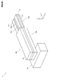
- FIG. 1 is a perspective view showing a configuration of a piezoelectric drive element according to the first embodiment.
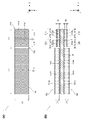
- FIG. 2A is a top view of the piezoelectric drive element according to the first embodiment.
- FIG. 2B is a cross-sectional view of the piezoelectric drive element according to the first embodiment.
- 3A to 3D are diagrams showing the steps for forming the piezoelectric drive element according to the first embodiment, respectively.
- FIG. 4 is a perspective view showing the configuration of the piezoelectric drive element according to the comparative example.
- FIG. 5 is a perspective view showing the configuration of the piezoelectric drive element according to the second embodiment.
- FIG. 6A is a top view of the piezoelectric drive element according to the second embodiment, and FIG.
- FIG. 6B is a cross-sectional view of the piezoelectric drive element according to the second embodiment.
- FIG. 7 (a) is a top view showing the configuration of the piezoelectric drive element according to the modified example of the second embodiment
- FIG. 7 (b) shows the configuration of the piezoelectric drive element according to the other modified example of the second embodiment. It is sectional drawing which shows.
- FIG. 8 is a perspective view showing the configuration of the piezoelectric drive element according to the third embodiment.
- 9 (a) and 9 (b) are a top view and a bottom view of the piezoelectric drive element according to the third embodiment, respectively.
- 10 (a) and 10 (b) are cross-sectional views of the piezoelectric drive element according to the third embodiment, respectively.
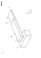
- FIG. 11 is a perspective view showing the configuration of the piezoelectric drive element according to the fourth embodiment.
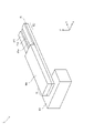
- FIG. 12 is a perspective view showing the configuration of the piezoelectric drive element according to the fifth embodiment.
- FIG. 13 is a perspective view showing another configuration of the piezoelectric drive element according to the fifth embodiment.
- 14 (a) to 14 (c) are cross-sectional views of the piezoelectric drive element according to the sixth embodiment, respectively.
- 15 (a) and 15 (b) are cross-sectional views of the piezoelectric drive element according to the modified example, respectively.
- the X-axis direction is the length direction of the piezoelectric body
- the Y-axis direction and the Z-axis direction are the width direction and the thickness direction of the piezoelectric body, respectively.
- the X-axis direction is also the direction connecting the fixed end and the free end of the piezoelectric drive element.
- FIG. 1 is a perspective view showing the configuration of the piezoelectric drive element 1 according to the first embodiment.
- the piezoelectric drive element 1 includes first piezoelectric bodies 10a and 10b, second piezoelectric bodies 20a and 20b, a shim material 30, and a support base 40.
- the shim material 30 is made of, for example, a metal material such as copper (Cu), silicon, or ceramics made of resin or oxide, and the first piezoelectric bodies 10a and 10b are formed on the upper surface and the lower surface of the shim material 30, respectively.
- the second piezoelectric bodies 20a and 20b are arranged.
- the shim material 30 is a member that converts the expansion and contraction of the first piezoelectric bodies 10a and 10b and the second piezoelectric bodies 20a and 20b in the X-axis direction into the deflection in the Z-axis direction, and is the first member in the X-axis direction. It has the flexibility to maintain a predetermined length against the expansion and contraction of the piezoelectric bodies 10a and 10b and the second piezoelectric bodies 20a and 20b, and to allow bending in the Z-axis direction.
- the fixed end E1 which is one end in the length direction is fixed to the support base 40.
- the first piezoelectric bodies 10a and 10b are arranged on the fixed end E1 side
- the second piezoelectric bodies 20a and 20b are arranged on the free end E2 side opposite to the fixed end.
- the first piezoelectric bodies 10a and 10b and the second piezoelectric bodies 20a and 20b expand and contract in the X-axis direction due to the driving voltage, so that the free end E2 is driven in the Z-axis direction. That is, when the upper first piezoelectric body 10a and the second piezoelectric body 20a contract in the X-axis direction due to the driving voltage, and the lower first piezoelectric body 10b and the second piezoelectric body 20b extend in the X-axis direction, the free end E2 is displaced in the positive direction of the Z axis.
- the free end E2 becomes Z. Displace in the negative axis direction.
- a driven body such as a mirror or an electrode is arranged at the free end E2.
- FIG. 2A is a top view of the piezoelectric drive element 1
- FIG. 2B is a cross-sectional view of the piezoelectric drive element 1.
- FIG. 2B shows a cross section of the piezoelectric drive element 1 when the intermediate position in the Y-axis direction is cut in a plane parallel to the XX plane.
- the upper first piezoelectric body 10a is configured by laminating an electrode layer 101a, a piezoelectric layer 102a, and an electrode layer 103a.
- the lower first piezoelectric body 10b is configured by laminating the electrode layer 101b, the piezoelectric layer 102b, and the electrode layer 103b.
- the upper second piezoelectric body 20a is configured by laminating the electrode layer 201a, the piezoelectric layer 202a, and the electrode layer 203a.
- the lower second piezoelectric body 20b is configured by laminating the electrode layer 201b, the piezoelectric layer 202b, and the electrode layer 203b.
- the piezoelectric layers 102a, 102b, 201a, and 201b are made of a piezoelectric material having a high piezoelectric constant, such as lead zirconate titanate (PZT).
- the electrode layers 101a, 103a, 101b, 103b, 201a, 203a, 201b, 203b are made of a material having low electrical resistance and high heat resistance, such as silver (Ag) and platinum (Pt).
- the upper first piezoelectric body 10a is arranged by forming a layer structure composed of the piezoelectric layer 102a and the upper and lower electrode layers 101a and 103a on the upper surface of the shim material 30.
- the lower first piezoelectric body 10b and the upper and lower second piezoelectric bodies 20a and 20b are also formed in the same manner.
- the thickness of the second piezoelectric bodies 20a and 20b is smaller than the thickness of the first piezoelectric bodies 10a and 10b. More specifically, the thickness D2 of the piezoelectric layers 202a and 202b constituting the second piezoelectric bodies 20a and 20b is smaller than the thickness of the piezoelectric layers 102a and 102b constituting the first piezoelectric bodies 10a and 10b.
- the thickness D2 can be set to about 1/5 of the thickness D1.
- the thickness D1 is set to about 250 ⁇ m
- the thickness D2 is set to about 50 ⁇ m.
- the thickness of all the electrode layers is the same as each other.
- the length L1 of the first piezoelectric bodies 10a and 10b is longer than the length L2 of the second piezoelectric bodies 20a and 20b.
- the widths of the first piezoelectric bodies 10a and 10b and the widths of the second piezoelectric bodies 20a and 20b are the same width W1.
- the displacement of the free end E2 shown in FIG. 1 is more affected by the drive by the first piezoelectric body 10a on the fixed end E1 side than the second piezoelectric body 20a on the free end E2 side.
- the length L1 of the first piezoelectric bodies 10a and 10b is preferably the length L2 or more of the second piezoelectric bodies 20a and 20b.
- the difference ⁇ L between the length L2 and the length L3 is as small as possible.
- the length L1 may be set to about four times the length L2, and the difference ⁇ L may be set to about 1/10 of the length L2.
- the length L1 is set to about 20 mm, and the length L2 is set to about 5 mm.
- the difference ⁇ L is set to about 0.5 mm.
- 3 (a) to 3 (d) are diagrams showing a process of forming the piezoelectric drive element 1.
- the method for forming the piezoelectric drive element 1 is not particularly limited.
- the piezoelectric drive element 1 may be formed by separately manufacturing each component and then joining the components.
- the piezoelectric drive element 1 may be formed by using a technique for manufacturing MEMS (MicroElectricMechanicalSystems).
- the piezoelectric drive element 1 is formed by manufacturing each component separately and then joining the components is shown.
- PZT thin plates 301 and 302 are formed by press-molding and sintering ceramic powder containing Pb, Ti, and Zr.
- Ag electrodes 401 and 402 are formed by printing on the front and back surfaces of the PZT thin plates 301 and 302.
- the PZT thin plates 301 and 302 on which the Ag electrodes 401 and 402 are printed on the front and back surfaces are individualized by dicing as shown in FIG. 3C to form the structures 501 and 502.
- the structures 501 and 502 are adhered to the front and back surfaces of the shim material 30 made of Cu to form the structure shown in FIG. 3 (d).
- the structure of FIG. 3D is adhered to the upper surface of the support base 40 to form the piezoelectric drive element 1 of FIG.
- any of the displacement amount of the free end E2, the generated force, and the resonance frequency of the element can be increased.
- this action will be described in comparison with a comparative example.
- 4 (a) and 4 (b) are perspective views showing the configuration of the piezoelectric drive element 2 according to Comparative Examples 1 and 2, respectively.
- the second piezoelectric bodies 20a and 20b are omitted. That is, in the configuration of Comparative Example 1, the piezoelectric body is not arranged on the free end E2 side of the first piezoelectric bodies 10a and 10b, and only the shim material 30 is left. Further, in Comparative Example 2, the second piezoelectric bodies 20a and 20b shown in FIG. 1 are omitted, and the first piezoelectric bodies 10a and 10b extend to the tip.
- the inventor of the present invention verified the displacement amount, generated force, and resonance frequency of the free end E2 with respect to the configuration of Comparative Example 1 and the configuration of Comparative Example 2 by simulation.
- the length of the fixed end E1 in the X-axis direction was set to 5 mm in both Comparative Examples 1 and 2. Further, in Comparative Example 2, the length of the first piezoelectric bodies 10a and 10b excluding the fixed end E1 portion in the X-axis direction is set to 26 mm, the thickness of the first piezoelectric bodies 10a and 10b is set to 0.3 mm, and the shim material. The thickness of 30 was set to 0.1 mm.
- the length of the tip portion from which the first piezoelectric bodies 10a and 10b have been removed is set to 5 mm in the X-axis direction, and the X-axis of the first piezoelectric bodies 10a and 10b excluding the fixed end E1 portion.
- the length in the direction was set to 21 mm.
- the thicknesses of the first piezoelectric bodies 10a and 10b and the shim material 30 in Comparative Example 1 were set to 0.3 mm and 0.1 mm, respectively, as in Comparative Example 2.
- the displacement amount of the free end E2 when the first piezoelectric bodies 10a and 10b were driven with a predetermined voltage was 128 ⁇ m, and the resonance frequency of the free end E2 was 525 Hz.
- the displacement amount of the free end E2 when the first piezoelectric bodies 10a and 10b were driven with the same voltage was 122 ⁇ m, and the resonance frequency of the free end E2 was 725 Hz.
- the resonance frequency of the element is remarkably increased while maintaining the displacement amount of the free end E2 at substantially the same level. I was able to.
- the resonance frequency of the free end E2 is increased by the arrangement of the second piezoelectric bodies 20a and 20b. A large decrease is suppressed. Therefore, according to the configuration of FIG. 1, the resonance frequency of the element can be increased while maintaining the displacement amount and the generated force of the free end E2 high.
- the thickness of the second piezoelectric bodies 20a and 20b is set to a thickness that can suppress a significant decrease in the displacement amount and the resonance frequency of the free end E2 while increasing the generating force of the free end E2.
- the thickness D2 of the second piezoelectric bodies 20a and 20b is preferably set to about 1/5 of the thickness D1 of the first piezoelectric bodies 10a and 10b as described above.
- the thickness D1 of the first piezoelectric bodies 10a and 10b may be set to about 250 ⁇ m
- the thickness D2 of the second piezoelectric bodies 20a and 20b may be set to about 50 ⁇ m.
- the resonance frequency of the free end E2 can be increased. Further, since the vicinity of the free end E2 is driven by the second piezoelectric bodies 20a and 20b, the displacement amount and the generated force of the free end E2 can be increased as compared with the case where only the first piezoelectric bodies 10a and 10b are used. Therefore, the resonance frequency of the element can be increased while maintaining the displacement amount and the generated force of the free end E2 high.
- the driving force of the piezoelectric body can be increased. .. As a result, the displacement amount and the generated force of the free end E2 can be effectively increased.
- one second piezoelectric body 20a and one 20b are arranged on the upper and lower surfaces of the shim material 30, but in the second embodiment, two second piezoelectric bodies are arranged on the upper and lower surfaces of the shim material 30. Is placed.
- FIG. 5 is a perspective view showing the configuration of the piezoelectric drive element 1 according to the second embodiment.
- the upper second piezoelectric bodies 21a and 22a are arranged on the upper surface of the shim material 30 so as to be aligned in the direction from the fixed end E1 to the free end E2 (X-axis direction).
- the lower second piezoelectric bodies 21b and 22b are arranged on the upper surface of the shim material 30 so as to line up in the direction (X-axis direction) from the fixed end E1 to the free end E2.
- the lengths of the second piezoelectric bodies 21a and 21b in the X-axis direction are the same, and the lengths of the second piezoelectric bodies 22a and 22b in the X-axis direction are the same.
- a gap is provided between the second piezoelectric bodies 21a and 21b and the second piezoelectric bodies 22a and 22b, and a gap is provided between the second piezoelectric bodies 22a and 22b and the first piezoelectric bodies 10a and 10b.
- the configuration of the first piezoelectric bodies 10a and 10b is the same as that of the first embodiment.
- FIG. 6A is a top view of the piezoelectric drive element 1 according to the second embodiment
- FIG. 6B is a cross-sectional view of the piezoelectric drive element 1 according to the second embodiment.
- FIG. 6B shows a cross section of the piezoelectric drive element 1 when the intermediate position in the Y-axis direction is cut in a plane parallel to the XX plane.
- the second piezoelectric body 21a is configured by laminating electrode layers 211a and 213a above and below the piezoelectric layer 212a, and the second piezoelectric body 21b is the piezoelectric layer 212b.
- the electrode layers 211b and 213b are laminated on the upper and lower sides of the above.
- the second piezoelectric body 22a is configured by laminating the electrode layers 221a and 223a above and below the piezoelectric layer 222a
- the second piezoelectric body 22b is configured by laminating the electrode layers 221b and 223b above and below the piezoelectric layer 222b. It is composed.
- the thickness D2 of the piezoelectric layers 212a, 212b, 222a, 222b in the second piezoelectric bodies 21a, 21b, 22a, 22b is the same as in the first embodiment, and the thickness D2 of the piezoelectric layers 102a, 102b of the first piezoelectric bodies 10a, 10b. small.
- the thickness of all the electrode layers is the same as each other. Therefore, the thickness of the second piezoelectric bodies 21a, 21b, 22a, 22b is smaller than the thickness of the first piezoelectric bodies 10a and 10b.
- the second piezoelectric bodies 21a, 21b, 22a, 22b are formed on the upper surface or the lower surface of the shim material 30 by the same method as in the first embodiment shown in FIGS. 3 (a) to 3 (d).
- the lower structure of FIG. 3B is separated into four pieces according to the lengths of the second piezoelectric bodies 21a, 21b, 22a, and 22b.
- each of the four individualized structures is adhered to the corresponding positions on the upper surface or the lower surface of the shim material 30. In this way, the structure shown in FIG. 6 (b) is formed.
- the method for forming the piezoelectric drive element 1 is not limited to this method.
- the second piezoelectric bodies 21a and 21b on the tip side are used for driving the free end E2 and the second piezoelectric bodies 22a and 22b on the root side are used for strain detection of the free end E2.
- the free end E2 is displaced in the Z-axis direction, one of the upper and lower second piezoelectric bodies 22a and 22b expands and the other contracts.
- the electric charge amount corresponding to the bending amount (displacement amount) of the free end E2 can be detected.
- the signal is monitored according to the displacement amount of the free end E2 when the first piezoelectric bodies 10a and 10b and the second piezoelectric bodies 21a and 21b are driven. Can be done.
- feedback control such as adjusting the voltage applied to the first piezoelectric bodies 10a and 10b and the second piezoelectric bodies 21a and 21b so that the free end E2 is displaced by the target displacement amount can be performed.
- the length L21 of the second piezoelectric bodies 21a and 21b in the X-axis direction and the length L22 of the second piezoelectric bodies 22a and 22b in the X-axis direction have an appropriate generating force due to the second piezoelectric bodies 21a and 21b.
- the length is set so that the signal generated at the free end E2 and corresponding to the amount of displacement of the free end E2 can be appropriately detected.
- the length L21 is long. From this point of view, the length L21 is preferably longer than the length L22.
- the second piezoelectric bodies 22a and 22b can be used as a monitor element for distortion detection according to the displacement amount of the free end E2.
- feedback control such as adjusting the voltage applied to the first piezoelectric bodies 10a and 10b and the second piezoelectric bodies 21a and 21b can be performed so that the displacement amount of the free end E2 becomes the target displacement amount.
- the second piezoelectric bodies 21a and 21b for driving the free end E2 are in the direction from the fixed end E1 toward the free end E2 (X-axis). It is arranged in a region symmetrical in the direction (Y-axis direction) perpendicular to the direction). As a result, the free end E2 can be driven evenly by the driving second piezoelectric bodies 21a and 21b, and twisting of the free end E2 can be suppressed.
- the second piezoelectric bodies 22a and 22b for detecting the distortion of the free end E2 are directed in the direction from the fixed end E1 toward the free end E2. It is arranged in a region symmetrical in the direction perpendicular to the X-axis direction (Y-axis direction). In this way, the second piezoelectric bodies 22a and 22b are evenly arranged without being unevenly distributed on one side in the Y-axis direction, so that the second piezoelectric bodies 22a and 22b become an unbalanced load and the free end E2 bends. Twisting can be suppressed. Therefore, while the distortion of the free end E2 is detected by the second piezoelectric bodies 22a and 22b, the free end E2 can be satisfactorily displaced by the driving second piezoelectric bodies 21a and 22a.
- the second piezoelectric bodies 21a and 21b and the second piezoelectric bodies 22a and 22b were used for strain detection, but the second piezoelectric bodies 21a and 21b are free end E2.
- the second piezoelectric bodies 22a and 22b may be used to drive the free end E2.
- FIG. 7A is a top view showing the configuration of the piezoelectric drive element 1 according to the modified example of the second embodiment.
- FIG. 7A shows a top view of the piezoelectric drive element 1, but the second piezoelectric body 22b arranged on the lower surface side of the piezoelectric drive element 1 is also the second piezoelectric body 22a on the upper surface side. It has the same configuration as.
- the width of the second piezoelectric bodies 22a and 22b in the Y-axis direction is narrower than the width of the shim material 30 in the Y-axis direction, that is, the width of the second piezoelectric bodies 21a and 21b on the distal end side in the Y-axis direction. ..
- the sizes of the upper and lower second piezoelectric bodies 22a and 22b are the same as each other.
- the second piezoelectric bodies 22a and 22b are rectangular in a plan view and are arranged at the center in the Y-axis direction.
- the second piezoelectric bodies 22a and 22b can be used as a monitor element for strain detection according to the displacement amount of the free end E2.
- the second piezoelectric body for driving extending in the X-axis direction may be further arranged on the positive and negative sides of the second piezoelectric bodies 22a and 22b on the Y-axis.
- the force of generating the free end E2 can be increased as compared with the configuration of the second embodiment.
- the second piezoelectric bodies 22a and 22b for detecting the strain corresponding to the displacement amount of the free end E2 are in the direction (X-axis direction) from the fixed end E1 to the free end E2. It is arranged in a region symmetrical in the vertical direction (Y-axis direction). In this way, the second piezoelectric bodies 22a and 22b are evenly arranged without being unevenly distributed on one side in the Y-axis direction, so that the second piezoelectric bodies 22a and 22b become an unbalanced load and the free end E2. Twisting in bending can be suppressed. Therefore, the free end E2 can be satisfactorily displaced by the driving second piezoelectric bodies 21a and 22a while the strain amount corresponding to the displacement amount of the free end E2 is detected by the second piezoelectric bodies 22a and 22b.
- FIG. 7B is a cross-sectional view showing the configuration of the piezoelectric drive element 1 according to another modification of the second embodiment. Similar to FIG. 6 (b), FIG. 7 (b) shows a cross section of the piezoelectric drive element 1 when the piezoelectric drive element 1 is cut at the center position in the Y-axis direction.
- the thickness of the piezoelectric layers 222a and 222b of the second piezoelectric bodies 22a and 22b is smaller than the thickness D2 of the piezoelectric layers 212a and 212b of the second piezoelectric bodies 21a and 21b on the distal end side.
- the upper and lower second piezoelectric bodies 22a and 22b have the same thickness.
- the thicknesses of the electrode layers of the second piezoelectric bodies 21a, 21b, 22a, and 22b are the same as each other. Therefore, the thickness of the second piezoelectric bodies 22a and 22b is smaller than the thickness of the second piezoelectric bodies 21a and 21b.
- the configuration of the second piezoelectric bodies 22a and 22b in a plan view is the same as that of the second embodiment.
- the second piezoelectric bodies 22a and 22b can be used as a detection element for monitoring the amount of strain according to the amount of displacement of the free end E2.
- the generated force of the free end E2 in the above can be increased, on the other hand, the resonance frequency of the element is lowered.
- the second piezoelectric bodies 22a and 22b used as the strain amount monitoring element in this modification do not require a driving force, that is, a generating force, and only need to secure a thickness and a size necessary for charge detection.
- the resonance frequency of the element can be increased while ensuring the distortion detection capability.
- the electrode layer and the piezoelectric layer constituting the second piezoelectric bodies 22a and 22b are sputtered using a metal mask. Can be formed on the upper and lower surfaces of the shim material 30.
- the second piezoelectric bodies 22a and 22b are formed on the upper and lower surfaces of the shim material 30, and then the first piezoelectric bodies 10a and 10b and the second piezoelectric bodies 10a and 10b formed by the same steps as in FIGS. 3A to 3C.
- the piezoelectric bodies 21a and 21b may be adhered to the upper and lower surfaces of the shim material 30.
- the width of the second piezoelectric bodies 22a and 22b in the Y-axis direction may be narrowed as in the case of FIG. 7 (a).
- the second piezoelectric body for driving which extends in the X-axis direction, may be further arranged on the positive and negative sides of the second piezoelectric bodies 22a and 22b on the Y-axis.
- the second piezoelectric body is divided in the X-axis direction.
- the second piezoelectric body is divided in the Y-axis direction.
- FIG. 8 is a perspective view showing the configuration of the piezoelectric drive element 1 according to the third embodiment.
- 9 (a) and 9 (b) are a top view and a bottom view of the piezoelectric drive element 1 according to the third embodiment, respectively, and FIGS. 10 (a) and 10 (b) are the third embodiment, respectively.
- It is sectional drawing of the piezoelectric drive element 1 which concerns on. 10 (a) shows a cross-sectional view of the piezoelectric drive element 1 cut at the position A1 in FIG. 9 (a), and FIG. 10 (b) shows piezoelectric at the position A2 in FIG. 9 (a).
- a cross-sectional view obtained by cutting the drive element 1 is shown.
- the cross-sectional view cut at the position of the second piezoelectric body 21a on the negative side of the Y-axis is the same as in FIG. 10 (b).
- the second piezoelectric body is divided in the Y-axis direction. That is, the plurality of second piezoelectric bodies are arranged side by side in the direction (Y-axis direction) where they intersect in the direction from the fixed end E1 to the free end E2.
- the second piezoelectric bodies 22a and 22b are arranged in the center in the Y-axis direction, and the second piezoelectric bodies 22a and 22b are arranged at both ends in the Y-axis direction. ..
- a gap is provided between the second piezoelectric bodies 21a and 21b and the second piezoelectric bodies 22a and 22b.
- the piezoelectric drive element 1 has a structure symmetrical in the Y-axis direction.
- the thickness D22 of the piezoelectric layers 222a and 222b of the second piezoelectric bodies 22a and 22b is smaller than the thickness D21 of the piezoelectric layers 222a and 222b of the second piezoelectric bodies 21a and 21b.
- the thicknesses of the electrode layers of the second piezoelectric bodies 21a, 21b, 22a, and 22b are the same as each other. Therefore, the thickness of the second piezoelectric bodies 22a and 22b is smaller than the thickness of the second piezoelectric bodies 21a and 21b.
- the configuration of the first piezoelectric bodies 10a and 10b is the same as that of the second embodiment.
- the central second piezoelectric bodies 22a and 22b can be formed by a sputtering method using a metal mask, as in the modified example of FIG. 7B. Also in this case, first, the central second piezoelectric bodies 22a and 22b are formed on the upper and lower surfaces of the shim material 30, and then the structures of the first piezoelectric bodies 10a and 10b and the structures of the second piezoelectric bodies 21a and 21b are formed. It is adhered to the upper and lower surfaces of the shim material 30.
- the thickness of the second piezoelectric bodies 21a, 21b, 22a and 22b is smaller than the thickness of the first piezoelectric bodies 10a and 10b, so that the displacement amount of the free end E2 is determined.
- the resonance frequency of the element can be increased while maintaining the generated force high.
- the second piezoelectric bodies 22a and 22b can be used for the strain detection of the free end E2 as in the second embodiment.
- the driving second piezoelectric bodies 21a and 21b extend from the free end E2 to the vicinity of the boundary between the first piezoelectric bodies 10a and 10b, and the first piezoelectric bodies 10a and 10b to the second piezoelectric body. Since 21a and 21b are continuously formed from the fixed end E1 to the free end E2 in the X-axis direction while having a short distance, the displacement caused by the second piezoelectric bodies 21a and 21b as compared with the second embodiment. The amount and generation power can be increased.
- the second piezoelectric bodies 22a and 22b for strain detection extend from the vicinity of the boundary between the first piezoelectric bodies 10a and 10b to the tip of the piezoelectric drive element 1 long in the X direction in which the change in the amount of deflection is large as compared with the second embodiment.
- the drive portion by the second piezoelectric bodies 21a and 21b is also formed at positions arranged in the direction of intersection (Y-axis direction) in the direction from the fixed end E1 to the free end E2 in the vicinity of the second piezoelectric bodies 22a and 22b. Therefore, the amount of charge detected by the second piezoelectric bodies 22a and 22b becomes larger, and the strain according to the amount of displacement of the free end E2 can be monitored more accurately.
- the second piezoelectric bodies 21a and 21b for driving the free end E2 are in the direction from the fixed end E1 toward the free end E2 (X-axis). It is arranged in a region symmetrical in the direction (Y-axis direction) perpendicular to the direction). As a result, the free end E2 can be driven evenly by the driving second piezoelectric bodies 21a and 21b, and twisting of the free end E2 can be suppressed.
- the second piezoelectric bodies 22a and 22b for detecting the distortion of the free end E2 are directed in the direction from the fixed end E1 toward the free end E2. It is arranged in a region symmetrical in the direction perpendicular to the X-axis direction (Y-axis direction). In this way, the second piezoelectric bodies 22a and 22b are evenly arranged without being unevenly distributed on one side in the Y-axis direction, so that the second piezoelectric bodies 22a and 22b become an unbalanced load and the free end E2 bends. Twisting can be suppressed. Therefore, while the distortion of the free end E2 is detected by the second piezoelectric bodies 22a and 22b, the free end E2 can be satisfactorily displaced by the driving second piezoelectric bodies 21a and 22a.
- the second piezoelectric bodies 22a and 22b for strain detection are arranged in the center in the Y-axis direction, but the second piezoelectric bodies 21a and 21b for driving are on the Y-axis.
- the second piezoelectric bodies 22a and 22b for strain detection may be arranged at the center of the direction at both ends in the Y-axis direction.
- the thickness of the second piezoelectric bodies 22a and 22b for detection was smaller than the thickness of the second piezoelectric bodies 21a and 21b for driving, but FIGS. 5 and 6 were formed.
- the thickness of the second piezoelectric bodies 22a and 22b for detection may be the same as the thickness of the second piezoelectric bodies 21a and 21b for driving.
- the length of the second piezoelectric body 21a and the length of the second piezoelectric body 22a were the same, but the length of the second piezoelectric body 21a and the second piezoelectric body 22a were the same. May be different in length.
- the first piezoelectric bodies 10a and 10b and the second piezoelectric bodies 20a and 20b are arranged on the upper and lower surfaces of the shim material 30, but the first piezoelectric body is placed on only one of the upper and lower surfaces of the shim material 30. And the second piezoelectric body may be arranged.
- FIG. 11 is a perspective view showing the configuration of the piezoelectric drive element 1 according to the fourth embodiment.
- the first piezoelectric body 10a and the second piezoelectric body 20a are arranged only on the upper surface of the shim material 30.
- the configurations of the first piezoelectric body 10a and the second piezoelectric body 20a are the same as those in the first embodiment.
- the first piezoelectric body 10a and the second piezoelectric body 20a are arranged on the upper surface of the shim material 30 in the same process as in FIGS. 3A to 3D, for example.
- the end portion of the shim material 30 on the fixed end E1 side is adhered to the support base 40.
- the first piezoelectric body 10a and the second piezoelectric body 20a expand and contract in the longitudinal direction (X-axis direction).
- the expansion and contraction of the first piezoelectric body 10a and the second piezoelectric body 20a is reduced by being restrained by the shim material 30.
- expansion and contraction becomes large in the vicinity of the surface opposite to the surface to which the shim material 30 of the first piezoelectric body 10a and the second piezoelectric body 20a is adhered.
- the thickness of the second piezoelectric body 20a is smaller than the thickness of the first piezoelectric body 10a, so that the displacement amount and the generating force of the free end E2 are maintained high while maintaining a high displacement amount and the generating force of the free end E2.
- the resonance frequency of the element can be increased.
- the first piezoelectric body 10a and the second piezoelectric body 20a are arranged only on the upper surface of the shim material 30, but the first piezoelectric body 10a and the second piezoelectric body 20a are arranged from the configuration of FIG. Omitted, the first piezoelectric body 10b and the second piezoelectric body 20b may be arranged only on the lower surface of the shim material 30.
- the first piezoelectric bodies 10a and 10b are arranged on both sides of the shim material 30 as in the first embodiment.
- the driving force is lower than in the case where the second piezoelectric bodies 20a and 20b are arranged. Therefore, in order to increase the displacement amount of the free end E2 by applying a large generated force to the free end E2, the first piezoelectric body and the second piezoelectric body are free ends from the fixed end E1 as in the first embodiment. It is preferable that they are arranged above and below the plane facing E2 (upper and lower surfaces of the shim material 30).
- the second piezoelectric body 20a is further divided into a plurality of parts.
- FIG. 12 is a perspective view showing the configuration of the piezoelectric drive element 1 according to the fifth embodiment.
- the second piezoelectric body is divided in the X-axis direction.
- the second piezoelectric bodies 21a and 22a are arranged side by side in the direction from the fixed end E1 to the free end E2 (X-axis direction).
- the piezoelectric drive element 1 of FIG. 12 has a configuration in which the lower first piezoelectric body 10b and the second piezoelectric bodies 22a and 22b are omitted from the piezoelectric drive element 1 of the second embodiment shown in FIGS. 5 to 6 (b). Is.
- the second piezoelectric body 22a can be used for detecting the strain of the free end E2, as in the second embodiment.
- the thickness of the second piezoelectric body 22a may be smaller than the thickness of the second piezoelectric body 21a.
- the width of the second piezoelectric body 22a may be narrower than the width of the second piezoelectric body 21a, and the second piezoelectric body for driving is in the region of the broken line in FIG. 7A. The body may be further placed.
- FIG. 13 is a perspective view showing another configuration of the piezoelectric drive element 1 according to the fifth embodiment.
- the two second piezoelectric bodies 21a and the second piezoelectric body 22a are arranged side by side in the direction (Y-axis direction) where they intersect in the direction from the fixed end E1 to the free end E2.
- the second piezoelectric body 22a is arranged in the center in the Y-axis direction, and the two second piezoelectric bodies 21a are arranged at both ends in the Y-axis direction.
- the thickness of the central second piezoelectric body 22a is smaller than the thickness of the second piezoelectric bodies 21a on both sides.
- the piezoelectric drive element 1 of FIG. 13 has a configuration in which the first piezoelectric body 10b and the second piezoelectric bodies 22a and 22b are omitted from the piezoelectric drive element 1 of the third embodiment shown in FIGS. 8 to 10 (b). Also in this configuration, after the first piezoelectric body 10a and the second piezoelectric body 20a are arranged on the upper surface of the shim material 30, the end portion of the shim material 30 on the fixed end E1 side is adhered to the support base 40.
- the second piezoelectric body 22a can be used for detecting the strain of the free end E2, as in the third embodiment.
- the thickness of the second piezoelectric body 22a may be the same as the thickness of the second piezoelectric body 21a.
- the second piezoelectric body 21a for driving may be arranged in the center in the Y-axis direction, and the second piezoelectric body 22a for strain detection may be arranged on both sides in the Y-axis direction. ..
- the length of the second piezoelectric body 21a and the length of the second piezoelectric body 22a may be different from each other.
- the shim material 30 of the first piezoelectric body 10a and the second piezoelectric body 21a is similar to the configuration example of FIG. Due to the difference in expansion and contraction of the first piezoelectric body 10a and the second piezoelectric body 21a in the vicinity of the surface to which the shim material 30 is adhered and in the vicinity of the surface opposite to the surface to which the shim material 30 is adhered, the shim material 30 and further the free end E2 is displaced in the Z-axis direction. As a result, the driven body arranged at the free end E2 is driven.
- the electric charge corresponding to the displacement amount of the free end E2 can be detected by using the second piezoelectric body 22a.
- feedback control is performed to displace the free end E2 to the target displacement amount.
- the second piezoelectric body 22a for strain detection is longer from the vicinity of the boundary of the first piezoelectric body 10a to the tip of the piezoelectric drive element 1 in the X direction in which the change in the amount of deflection is larger than that of the configuration of FIG.
- the second piezoelectric body 21a is formed by arranging and arranging the drive portion by the second piezoelectric body 21a at a position where the second piezoelectric body 22a is lined up in a direction (Y-axis direction) intersecting in the direction from the fixed end E1 to the free end E2 in the vicinity of the second piezoelectric body 22a. Therefore, the amount of detected charge of the second piezoelectric body 22a becomes larger, and the amount of strain corresponding to the amount of displacement of the free end E2 can be monitored more accurately.
- the thickness of the second piezoelectric bodies 21a and 22a is smaller than the thickness of the first piezoelectric body 10a, so that the displacement amount and the generating force of the free end E2 are maintained high. At the same time, the resonance frequency of the element can be increased.
- the displacement amount of the free end E2 becomes the target displacement amount while the generated force of the free end E2 is supplemented by the second piezoelectric body 21a. Feedback control can be performed.
- the first piezoelectric body 10a and the second piezoelectric bodies 21a and 22a are arranged only on one side of the shim material 30, the first piezoelectric body 10a and the second piezoelectric body 21a and 22a are arranged on both sides of the shim material 30 as in the second and third embodiments.
- the driving force is lower than when the first piezoelectric bodies 10a and 10b and the second piezoelectric bodies 21a, 21b, 22a and 22b are arranged. Therefore, in order to increase the displacement amount of the free end E2 by applying a large generated force to the free end E2, the first piezoelectric body and the second piezoelectric body are free ends from the fixed end E1 as in the first embodiment. It is preferable that they are arranged above and below the plane facing E2 (upper and lower surfaces of the shim material 30).
- the first piezoelectric bodies 10a and 10b and the second piezoelectric bodies 21a, 21b, 22a and 22b are arranged on the upper and lower surfaces of the shim material 30, but in the sixth embodiment, the shim material 30 is omitted. To.
- FIG. 14 (a) is a cross-sectional view showing the configuration of the piezoelectric drive element 1 when the shim material 30 is omitted from the configuration of the first embodiment shown in FIGS. 1 to 2 (b).
- FIG. 14A shows a cross-sectional view of the structure of the piezoelectric drive element 1 excluding the support base 40 cut at the center position in the Y-axis direction in a plane parallel to the XX plane.
- FIG. 14 (b) is a cross-sectional view showing the configuration of the piezoelectric drive element 1 when the shim material 30 is omitted from the configuration of the second embodiment shown in FIGS. 5 to 6 (b).
- FIG. 14B shows a cross-sectional view of the structure of the piezoelectric drive element 1 excluding the support base 40 cut at the center position in the Y-axis direction in a plane parallel to the XX plane.
- FIG. 14 (c) is a cross-sectional view showing the configuration of the piezoelectric drive element 1 when the shim material 30 is omitted from the configuration of the modified example of the second embodiment shown in FIG. 7 (b).
- FIG. 14C shows a cross-sectional view of the structure of the piezoelectric drive element 1 excluding the support base 40 cut at the center position in the Y-axis direction in a plane parallel to the XX plane.
- the electrode layer 103 is shared by the first piezoelectric bodies 10a and 10b and the second piezoelectric bodies 20a and 20b, and in the configurations of FIGS. 14 (b) and 14 (c), the electrode layer 103 is the first. 1 Piezoelectric body 10a, 10b and second piezoelectric body 21a, 21b, 22a, 22b are shared.
- the shared electrode layer 103 is connected to the ground, and a driving voltage is applied to the electrode layers 101a, 101b, 201a, 201b, 211a, and 211b.
- the polarization directions of the piezoelectric layers 102a, 202a, 212a of the first piezoelectric bodies 10a, 20a, 21a and the piezoelectric layers 102b, 202b, 212b of the second piezoelectric bodies 10b, 20b, 21b are set in the Z-axis direction.
- the first piezoelectric is applied to the electrode layers 101a, 201a, 211a and the electrode layers 101b, 201b, 211b by applying a voltage having a phase opposite to the ground potential of the electrode layer 103.
- the polarization directions of the piezoelectric layers 102a, 202a, 212a of the first piezoelectric bodies 10a, 20a, 21a and the piezoelectric layers 102b, 202b, 212b of the second piezoelectric bodies 10b, 20b, 21b are positive and negative in the Z-axis direction.
- the first piezoelectric material is formed by applying a voltage having the same phase to the ground potential of the electrode layer 103 to the electrode layers 101a, 201a, 211a and the electrode layers 101b, 201b, 211b.
- the elongation of 10a, 20a, 21a and the contraction of the second piezoelectric bodies 10b, 20b, 21b, or the contraction of the first piezoelectric bodies 10a, 20a, 21a and the expansion of the second piezoelectric bodies 10b, 20b, 21b can occur at the same time. can.
- the respective polarization directions of the piezoelectric layers 102a, 202a, 212a of the first piezoelectric bodies 10a, 20a, 21a and the piezoelectric layers 102b, 202b, 212b of the second piezoelectric bodies 10b, 20b, 21b are piezoelectrically driven.
- the polarization process which comprises a step of previously applying a voltage higher than the drive voltage to be used between the electrode layer 103 and each of the electrode layers 101a, 101b, 201a, 201b, 211a, and 211b after the element 1 is manufactured. Determined by the polarity of the voltage.
- the free end E2 is displaced in the Z-axis direction due to the expansion and contraction of.
- the second piezoelectric bodies 22a and 22b can be used as a detection element for monitoring the amount of strain according to the amount of displacement of the free end E2.
- the thicknesses of the second piezoelectric bodies 22a and 22b are smaller than those of the configuration of FIG. 14 (b), so that the ability to detect the strain amount is secured.
- the resonance frequency of the element can be increased.
- the piezoelectric drive element 1 shown in FIG. 14A is formed as follows, for example.
- Ag electrodes 401 and 402 are formed by printing only on one surface of the PZT thin plates 301 and 302 formed by the same method as in FIG. 3 (a). Next, the PZT thin plates 301 and 302 having the Ag electrodes 401 and 402 printed on the surface are separated by dicing. The structure thus individualized is adhered to the upper and lower surfaces of a conductive plate made of a copper plate or the like. As a result, the structure shown in FIG. 14 (a) is formed.
- the PZT thin plate 301 and the PZT thin plate 302 correspond to the piezoelectric layers 102a and 102b and the piezoelectric layers 202a and 202b of FIG. 14 (a), respectively, and the Ag electrode 401 and the Ag electrode 402 of FIG. 14 (a), respectively.
- the conductive plate corresponds to the electrode layer 103 in FIG. 14 (a).
- the electrode layer 103 is shared by the first piezoelectric bodies 10a and 10b and the second piezoelectric bodies 20a and 20b.
- the structures of the first piezoelectric bodies 10a and 10b and the second piezoelectric bodies 21a, 21b, 22a and 22b formed by the same method are common electrode layers from the conductive plate.
- the piezoelectric drive element 1 is formed by being adhered to the upper and lower surfaces of the 103.
- the second piezoelectric bodies 22a and 22b may be formed by a sputtering method using a metal mask, as in the case of FIG. 7 (b).
- the thickness of the second piezoelectric bodies 21a, 21b, 22a, 22b is smaller than the thickness of the first piezoelectric bodies 10a and 10b, so that the displacement amount of the free end E2 is determined.
- the resonance frequency of the element can be increased while maintaining the generated force high.
- the displacement amount of the free end E2 is increased while the generated force of the free end E2 is supplemented by the second piezoelectric bodies 21a and 21b.
- the feedback control can be performed so that the displacement amount becomes the target.
- the configuration in which the shim material 30 is omitted from the configurations of the modified examples of the first embodiment, the second embodiment and the second embodiment is shown above, the configuration of the third embodiment shown in FIGS. 8 to 10 (b) is shown.
- the shim material 30 may be omitted from the configuration to form the piezoelectric drive element 1. In this case as well, the same effect as described above can be achieved.
- a gap is provided between the first piezoelectric bodies 10a and 10b and the second piezoelectric bodies 20a, 20b, 21a, 21b, 22a and 22b, but the first piezoelectric bodies 10a and 10b
- the piezoelectric layer and the piezoelectric layers of the second piezoelectric bodies 20a, 20b, 21a, 21b, 22a, and 22b may be connected to each other.
- FIG. 15A is a diagram showing a configuration example in which the piezoelectric layer 102a and the piezoelectric layer 202a are connected, and the piezoelectric layer 102b and the piezoelectric layer 202b are connected in the configuration of the first embodiment.
- FIG. 15B shows a case where the piezoelectric layer 102a, the piezoelectric layer 222a, and the piezoelectric layer 212a are connected, and the piezoelectric layer 102b, the piezoelectric layer 222b, and the piezoelectric layer 212b are connected in the configuration of the second embodiment. It is a figure which shows the configuration example of.
- the thickness D2 of the piezoelectric layers 212a, 212b, 222a, 222b is smaller than the thickness D1 of the piezoelectric layers 102a, 102b.
- the electrodes on the surface side of the first piezoelectric bodies 10a and 10b and the electrodes on the surface side of the second piezoelectric bodies 20a, 20b, 21a, 21b, 22a, and 22b are separated from each other.
- the electrodes on the shim material 30 side of the first piezoelectric bodies 10a and 10b and the electrodes on the shim material 30 side of the second piezoelectric bodies 20a, 20b, 21a, 21b, 22a, and 22b are as shown in FIGS. May be shared with.
- the shared electrode layers 103a and 103b are connected to the ground, and a driving voltage is applied to the electrode layers 101a, 101b, 201a, 201b, 211a and 211b on the surface side.
- the free end E2 can be displaced, and in the configuration of FIG. 15B, the second piezoelectric bodies 22a and 22b can be used to detect the strain amount according to the displacement amount of the free end E2. ..
- the piezoelectric layers of the first piezoelectric bodies 10a and 10b and the piezoelectric layers of the second piezoelectric bodies 20a, 20b, 21a, 21b, 22a and 22b are connected to each other. May be.
- the second piezoelectric bodies 22a and 22b are used to detect the amount of strain according to the amount of displacement of the free end E2, but both or one of these piezoelectric bodies may be used. It may be used to drive the free end E2. Also in the configuration of the sixth embodiment shown in FIGS. 14 (b) and 14 (c) and the configuration of the modified example shown in FIG. 15 (b), both or one of the second piezoelectric bodies 22a and 22b are free end E2. May be used to drive the.
- the first piezoelectric bodies 10a and 10b are integrally formed, but the first piezoelectric bodies 10a and 10b are in the length direction (X-axis direction) or the width direction (Y). It may be divided into a plurality of parts in the axial direction).
- the number of divisions of the second piezoelectric body is not limited to the number of divisions shown in the above embodiments 2, 3, 5, and 6, and the second piezoelectric body may be divided by another number of divisions.
- each part of the piezoelectric drive element 1 are not limited to those shown in the above embodiments 1 to 6 and the modified examples, and can be appropriately changed.
- Piezoelectric drive element 10a, 10b First piezoelectric body 20a, 20b, 21a, 21b, 22a, 22b Second piezoelectric body E1 Fixed end E2 Free end
Landscapes
- Engineering & Computer Science (AREA)
- Manufacturing & Machinery (AREA)
- Chemical & Material Sciences (AREA)
- Inorganic Chemistry (AREA)
- General Electrical Machinery Utilizing Piezoelectricity, Electrostriction Or Magnetostriction (AREA)
Abstract
Description
図1は、実施形態1に係る圧電駆動素子1の構成を示す斜視図である。 <
FIG. 1 is a perspective view showing the configuration of the
上記実施形態1によれば、以下の効果が奏され得る。 <Effect of
According to the first embodiment, the following effects can be achieved.
上記実施形態1では、シム材30の上下面に第2圧電体20a、20bがそれぞれ1つずつ配置されたが、実施形態2では、シム材30の上下面にそれぞれ2つずつ第2圧電体が配置される。 <
In the first embodiment, one second
本実施形態2においても、上記実施形態1と同様、第2圧電体21a、21b、22a、22bの厚みが第1圧電体10a、10bの厚みより小さいため、自由端E2の変位量と発生力を高く維持しつつ、素子の共振周波数を高めることができる。 <Effect of
Also in the second embodiment, as in the first embodiment, since the thickness of the second
図7(a)は、実施形態2の変更例に係る圧電駆動素子1の構成を示す上面図である。便宜上、図7(a)には、圧電駆動素子1の上面図が示されているが、圧電駆動素子1の下面側に配置されている第2圧電体22bも上面側の第2圧電体22aと同様の構成である。 <Change example>
FIG. 7A is a top view showing the configuration of the
上記実施形態2では、第2圧電体がX軸方向に分割された。これに対し、実施形態3では、第2圧電体がY軸方向に分割される。 <Embodiment 3>
In the second embodiment, the second piezoelectric body is divided in the X-axis direction. On the other hand, in the third embodiment, the second piezoelectric body is divided in the Y-axis direction.
本実施形態3においても、上記実施形態1、2と同様、第2圧電体21a、21b、22a、22bの厚みが第1圧電体10a、10bの厚みより小さいため、自由端E2の変位量、発生力を高く維持しつつ、素子の共振周波数を高めることができる。 <Effect of Embodiment 3>
Also in the third embodiment, as in the first and second embodiments, the thickness of the second
上記実施形態1では、シム材30の上下面に第1圧電体10a、10bと第2圧電体20a、20bが配置されたが、シム材30の上下面の何れか一方のみに第1圧電体と第2圧電体が配置されてもよい。 <Embodiment 4>
In the first embodiment, the first
本実施形態4においても、上記実施形態1~3と同様、第2圧電体20aの厚みが第1圧電体10aの厚みより小さいため、自由端E2の変位量、発生力を高く維持しつつ、素子の共振周波数を高めることができる。 <Effect of Embodiment 4>
Also in the fourth embodiment, as in the first to third embodiments, the thickness of the second
実施形態5では、実施形態4の構成において、さらに、第2圧電体20aが複数に分割される。 <Embodiment 5>
In the fifth embodiment, in the configuration of the fourth embodiment, the second
本実施形態5においても、上記実施形態1~4と同様、第2圧電体21a、22aの厚みが第1圧電体10aの厚みより小さいため、自由端E2の変位量、発生力を高く維持しつつ、素子の共振周波数を高めることができる。 <Effect of Embodiment 5>
Also in the fifth embodiment, as in the first to fourth embodiments, the thickness of the second
上記実施形態1~3では、シム材30の上下面に第1圧電体10a、10bと第2圧電体21a、21b、22a、22bが配置されたが、実施形態6ではシム材30が省略される。 <Embodiment 6>
In the first to third embodiments, the first
本実施形態6においても、上記実施形態1~5と同様、第2圧電体21a、21b、22a、22bの厚みが第1圧電体10a、10bの厚みより小さいため、自由端E2の変位量、発生力を高く維持しつつ、素子の共振周波数を高めることができる。 <Effect of Embodiment 6>
Also in the sixth embodiment, as in the first to fifth embodiments, the thickness of the second
上記実施形態1~6では、第1圧電体10a、10bと第2圧電体20a、20b、21a、21b、22a、22bとの間に隙間が設けられたが、第1圧電体10a、10bの圧電層と第2圧電体20a、20b、21a、21b、22a、22bの圧電層とが繋がっていてもよい。 <Other changes>
In the
10a、10b 第1圧電体
20a、20b、21a、21b、22a、22b 第2圧電体
E1 固定端
E2 自由端 1
Claims (11)
- 一方の固定端が支持台に固定され、他方の自由端が駆動される片持ち式の圧電駆動素子であって、
前記固定端側に配置された第1圧電体と、
前記固定端よりも前記自由端側に配置された第2圧電体と、を備え、
前記第2圧電体の厚みが、前記第1圧電体の厚みよりも小さい、
ことを特徴とする圧電駆動素子。
A cantilevered piezoelectric drive element in which one fixed end is fixed to a support and the other free end is driven.
The first piezoelectric body arranged on the fixed end side and
A second piezoelectric body arranged on the free end side of the fixed end is provided.
The thickness of the second piezoelectric body is smaller than the thickness of the first piezoelectric body.
A piezoelectric drive element characterized by this.
- 請求項1に記載の圧電駆動素子において、
前記第2圧電体は、複数に分割されている、
ことを特徴とする圧電駆動素子。
In the piezoelectric drive element according to claim 1,
The second piezoelectric body is divided into a plurality of parts.
A piezoelectric drive element characterized by this.
- 請求項2に記載の圧電駆動素子において、
前記複数に分割された前記第2圧電体は、前記固定端から前記自由端に向かう方向に並んでいる、
ことを特徴とする圧電駆動素子。
In the piezoelectric drive element according to claim 2,
The second piezoelectric body divided into the plurality of pieces is arranged in a direction from the fixed end to the free end.
A piezoelectric drive element characterized by this.
- 請求項2に記載の圧電駆動素子において、
前記複数に分割された前記第2圧電体は、前記固定端から前記自由端に向かう方向に交差する方向に並んでいる、
ことを特徴とする圧電駆動素子。
In the piezoelectric drive element according to claim 2,
The second piezoelectric body divided into the plurality of pieces is arranged in a direction intersecting in a direction from the fixed end to the free end.
A piezoelectric drive element characterized by this.
- 請求項2ないし4の何れか一項に記載の圧電駆動素子において、
複数に分割された一の前記第2圧電体の厚みが、複数に分割された他の前記第2圧電体の厚みよりも小さい、
ことを特徴とする圧電駆動素子。
The piezoelectric drive element according to any one of claims 2 to 4.
The thickness of one of the second piezoelectric bodies divided into a plurality of parts is smaller than the thickness of the other second piezoelectric body divided into a plurality of pieces.
A piezoelectric drive element characterized by this.
- 請求項2ないし5の何れか一項に記載の圧電駆動素子において、
前記複数の第2圧電体は、前記自由端を駆動するための圧電体と、前記自由端の歪を検出するための圧電体とに区分される、
ことを特徴とする圧電駆動素子。
The piezoelectric drive element according to any one of claims 2 to 5.
The plurality of second piezoelectric bodies are classified into a piezoelectric body for driving the free end and a piezoelectric body for detecting the distortion of the free end.
A piezoelectric drive element characterized by this.
- 請求項6に記載の圧電駆動素子において、
前記自由端の歪を検出するための前記第2圧電体の厚みは、前記自由端を駆動するための前記第2圧電体の厚みよりも小さい、
ことを特徴とする圧電駆動素子。
In the piezoelectric drive element according to claim 6,
The thickness of the second piezoelectric body for detecting the distortion of the free end is smaller than the thickness of the second piezoelectric body for driving the free end.
A piezoelectric drive element characterized by this.
- 請求項6または7に記載の圧電駆動素子において、
前記自由端を駆動するための前記第2圧電体は、前記固定端から前記自由端に向かう方向に垂直な方向に対称な領域に配置されている、
ことを特徴とする圧電駆動素子。
In the piezoelectric drive element according to claim 6 or 7.
The second piezoelectric body for driving the free end is arranged in a region symmetrical in a direction perpendicular to the direction from the fixed end to the free end.
A piezoelectric drive element characterized by this.
- 請求項6ないし8の何れか一項に記載の圧電駆動素子において、
前記自由端の歪を検出するための前記第2圧電体は、前記固定端から前記自由端に向かう方向に垂直な方向に対称な領域に配置されている、
ことを特徴とする圧電駆動素子。
The piezoelectric drive element according to any one of claims 6 to 8.
The second piezoelectric body for detecting the strain at the free end is arranged in a region symmetrical in a direction perpendicular to the direction from the fixed end toward the free end.
A piezoelectric drive element characterized by this.
- 請求項1ないし9の何れか一項に記載の圧電駆動素子において、
前記第1圧電体および前記第2圧電体は、板状のシム材に重なるように配置されている、
ことを特徴とする圧電駆動素子。
The piezoelectric drive element according to any one of claims 1 to 9.
The first piezoelectric body and the second piezoelectric body are arranged so as to overlap the plate-shaped shim material.
A piezoelectric drive element characterized by this.
- 請求項1ないし10の何れか一項に記載の圧電駆動素子において、
前記第1圧電体および前記第2圧電体は、前記固定端から前記自由端に向かう平面の上下にそれぞれ配置されている、
ことを特徴とする圧電駆動素子。 The piezoelectric drive element according to any one of claims 1 to 10.
The first piezoelectric body and the second piezoelectric body are arranged above and below the plane from the fixed end to the free end, respectively.
A piezoelectric drive element characterized by this.
Priority Applications (3)
| Application Number | Priority Date | Filing Date | Title |
|---|---|---|---|
| CN202180080805.XA CN116615971A (en) | 2020-12-18 | 2021-11-22 | Piezoelectric driving element |
| JP2022569811A JPWO2022130911A1 (en) | 2020-12-18 | 2021-11-22 | |
| US18/210,541 US20230329118A1 (en) | 2020-12-18 | 2023-06-15 | Piezoelectric driving element |
Applications Claiming Priority (2)
| Application Number | Priority Date | Filing Date | Title |
|---|---|---|---|
| JP2020-209955 | 2020-12-18 | ||
| JP2020209955 | 2020-12-18 |
Related Child Applications (1)
| Application Number | Title | Priority Date | Filing Date |
|---|---|---|---|
| US18/210,541 Continuation US20230329118A1 (en) | 2020-12-18 | 2023-06-15 | Piezoelectric driving element |
Publications (1)
| Publication Number | Publication Date |
|---|---|
| WO2022130911A1 true WO2022130911A1 (en) | 2022-06-23 |
Family
ID=82059073
Family Applications (1)
| Application Number | Title | Priority Date | Filing Date |
|---|---|---|---|
| PCT/JP2021/042775 WO2022130911A1 (en) | 2020-12-18 | 2021-11-22 | Piezoelectric driving element |
Country Status (4)
| Country | Link |
|---|---|
| US (1) | US20230329118A1 (en) |
| JP (1) | JPWO2022130911A1 (en) |
| CN (1) | CN116615971A (en) |
| WO (1) | WO2022130911A1 (en) |
Cited By (1)
| Publication number | Priority date | Publication date | Assignee | Title |
|---|---|---|---|---|
| WO2024161923A1 (en) * | 2023-01-31 | 2024-08-08 | 富士フイルム株式会社 | Electromagnetic wave control element |
Citations (4)
| Publication number | Priority date | Publication date | Assignee | Title |
|---|---|---|---|---|
| JPS60208880A (en) * | 1984-04-03 | 1985-10-21 | Sumitomo Special Metals Co Ltd | Piezoelectric bimorph vibrator |
| JPH04162784A (en) * | 1990-10-26 | 1992-06-08 | Mitsui Petrochem Ind Ltd | Bending displacement type actuator |
| JP2007273800A (en) * | 2006-03-31 | 2007-10-18 | Toshiba Corp | Piezoelectric drive-type mems actuator |
| JP2013081287A (en) * | 2011-10-03 | 2013-05-02 | Seiko Epson Corp | Power generating device, electronic device, transportation means, and method for controlling power generating device |
-
2021
- 2021-11-22 WO PCT/JP2021/042775 patent/WO2022130911A1/en active Application Filing
- 2021-11-22 JP JP2022569811A patent/JPWO2022130911A1/ja active Pending
- 2021-11-22 CN CN202180080805.XA patent/CN116615971A/en active Pending
-
2023
- 2023-06-15 US US18/210,541 patent/US20230329118A1/en active Pending
Patent Citations (4)
| Publication number | Priority date | Publication date | Assignee | Title |
|---|---|---|---|---|
| JPS60208880A (en) * | 1984-04-03 | 1985-10-21 | Sumitomo Special Metals Co Ltd | Piezoelectric bimorph vibrator |
| JPH04162784A (en) * | 1990-10-26 | 1992-06-08 | Mitsui Petrochem Ind Ltd | Bending displacement type actuator |
| JP2007273800A (en) * | 2006-03-31 | 2007-10-18 | Toshiba Corp | Piezoelectric drive-type mems actuator |
| JP2013081287A (en) * | 2011-10-03 | 2013-05-02 | Seiko Epson Corp | Power generating device, electronic device, transportation means, and method for controlling power generating device |
Cited By (1)
| Publication number | Priority date | Publication date | Assignee | Title |
|---|---|---|---|---|
| WO2024161923A1 (en) * | 2023-01-31 | 2024-08-08 | 富士フイルム株式会社 | Electromagnetic wave control element |
Also Published As
| Publication number | Publication date |
|---|---|
| CN116615971A (en) | 2023-08-18 |
| US20230329118A1 (en) | 2023-10-12 |
| JPWO2022130911A1 (en) | 2022-06-23 |
Similar Documents
| Publication | Publication Date | Title |
|---|---|---|
| CN107797274B (en) | Micromechanical device and method for two-dimensional deflection of light | |
| DE102008012825B4 (en) | Micromechanical device with tilted electrodes | |
| JP4289511B2 (en) | Piezoelectric actuator | |
| US10411182B2 (en) | Drive apparatus | |
| JP5914355B2 (en) | Piezoelectric actuator | |
| US20100231087A1 (en) | Micro oscillating element | |
| JP2006518094A (en) | BENDING ACTUATOR AND SENSOR COMPOSED OF MODELING ACTIVE MATERIAL AND METHOD FOR PRODUCING THEM | |
| JP3709847B2 (en) | Electrostatic actuator | |
| WO2012073741A1 (en) | Piezoelectric power generating device | |
| WO2014155448A1 (en) | Mirror device | |
| WO2022130911A1 (en) | Piezoelectric driving element | |
| KR20190041006A (en) | Piezoelectric actuator, method of manufacturing deformed mirror and deformed mirror | |
| WO2016080317A1 (en) | Optical element | |
| US8134277B2 (en) | Electrostatic comb actuator | |
| WO2020152905A1 (en) | Stacked piezoelectric element and piezoelectric actuator | |
| EP1692856A2 (en) | Transverse electrodisplacive actuator array | |
| JP2007168065A (en) | Structure of vertical comb electrode, micro light scanner provided with this, micro-actuator and electrostatic sensor | |
| US20190237653A1 (en) | Multi-layer piezoelectric ceramic component and piezoelectric device | |
| US20060050419A1 (en) | Integrated wavefront correction module | |
| US20170003500A1 (en) | Drive apparatus | |
| US9806250B2 (en) | Piezoelectric actuator | |
| JPS61150287A (en) | Piezoelectric displacement device | |
| US20230217828A1 (en) | Actuator | |
| JPS61285424A (en) | Optical beam deflector | |
| JP7467511B2 (en) | Piezoelectric element |
Legal Events
| Date | Code | Title | Description |
|---|---|---|---|
| 121 | Ep: the epo has been informed by wipo that ep was designated in this application |
Ref document number: 21906274 Country of ref document: EP Kind code of ref document: A1 |
|
| ENP | Entry into the national phase |
Ref document number: 2022569811 Country of ref document: JP Kind code of ref document: A |
|
| WWE | Wipo information: entry into national phase |
Ref document number: 202180080805.X Country of ref document: CN |
|
| NENP | Non-entry into the national phase |
Ref country code: DE |
|
| 122 | Ep: pct application non-entry in european phase |
Ref document number: 21906274 Country of ref document: EP Kind code of ref document: A1 |