WO2022130600A1 - Dispositif d'inhalation, dispositif terminal et programme - Google Patents
Dispositif d'inhalation, dispositif terminal et programme Download PDFInfo
- Publication number
- WO2022130600A1 WO2022130600A1 PCT/JP2020/047333 JP2020047333W WO2022130600A1 WO 2022130600 A1 WO2022130600 A1 WO 2022130600A1 JP 2020047333 W JP2020047333 W JP 2020047333W WO 2022130600 A1 WO2022130600 A1 WO 2022130600A1
- Authority
- WO
- WIPO (PCT)
- Prior art keywords
- heating
- suction device
- operation setting
- unit
- information
- Prior art date
Links
- 238000010438 heat treatment Methods 0.000 claims abstract description 499
- 238000012937 correction Methods 0.000 claims abstract description 156
- 239000000443 aerosol Substances 0.000 claims abstract description 78
- 238000004891 communication Methods 0.000 claims abstract description 50
- 239000000758 substrate Substances 0.000 claims abstract description 17
- 239000000463 material Substances 0.000 claims description 67
- 238000000034 method Methods 0.000 claims description 32
- 230000007704 transition Effects 0.000 claims description 22
- 230000006866 deterioration Effects 0.000 claims description 16
- 230000007246 mechanism Effects 0.000 abstract description 4
- 230000015556 catabolic process Effects 0.000 abstract 1
- 238000006731 degradation reaction Methods 0.000 abstract 1
- 238000001514 detection method Methods 0.000 description 84
- 239000000796 flavoring agent Substances 0.000 description 21
- 235000019634 flavors Nutrition 0.000 description 21
- 238000003860 storage Methods 0.000 description 20
- 230000005540 biological transmission Effects 0.000 description 15
- 230000003647 oxidation Effects 0.000 description 15
- 238000007254 oxidation reaction Methods 0.000 description 15
- 238000012545 processing Methods 0.000 description 14
- 238000010586 diagram Methods 0.000 description 13
- 230000008569 process Effects 0.000 description 12
- 230000007423 decrease Effects 0.000 description 10
- 230000008859 change Effects 0.000 description 9
- 230000006870 function Effects 0.000 description 8
- 239000000126 substance Substances 0.000 description 4
- 235000019640 taste Nutrition 0.000 description 4
- 238000003303 reheating Methods 0.000 description 3
- 230000004044 response Effects 0.000 description 3
- 230000007613 environmental effect Effects 0.000 description 2
- 239000012530 fluid Substances 0.000 description 2
- 239000011810 insulating material Substances 0.000 description 2
- 238000009413 insulation Methods 0.000 description 2
- 238000004519 manufacturing process Methods 0.000 description 2
- 238000012986 modification Methods 0.000 description 2
- 230000004048 modification Effects 0.000 description 2
- 238000003825 pressing Methods 0.000 description 2
- HBBGRARXTFLTSG-UHFFFAOYSA-N Lithium ion Chemical compound [Li+] HBBGRARXTFLTSG-UHFFFAOYSA-N 0.000 description 1
- 238000004364 calculation method Methods 0.000 description 1
- 239000003990 capacitor Substances 0.000 description 1
- 238000004590 computer program Methods 0.000 description 1
- 230000003247 decreasing effect Effects 0.000 description 1
- 239000003571 electronic cigarette Substances 0.000 description 1
- 239000000446 fuel Substances 0.000 description 1
- 230000020169 heat generation Effects 0.000 description 1
- 230000006872 improvement Effects 0.000 description 1
- 230000006698 induction Effects 0.000 description 1
- 230000010365 information processing Effects 0.000 description 1
- 239000007788 liquid Substances 0.000 description 1
- 229910001416 lithium ion Inorganic materials 0.000 description 1
- 239000000203 mixture Substances 0.000 description 1
- 230000003287 optical effect Effects 0.000 description 1
- 230000002250 progressing effect Effects 0.000 description 1
- 230000000750 progressive effect Effects 0.000 description 1
- 230000001007 puffing effect Effects 0.000 description 1
- 230000009467 reduction Effects 0.000 description 1
- 239000007787 solid Substances 0.000 description 1
- 239000013589 supplement Substances 0.000 description 1
- 238000012546 transfer Methods 0.000 description 1
- 238000011144 upstream manufacturing Methods 0.000 description 1
Images


Classifications
-
- A—HUMAN NECESSITIES
- A24—TOBACCO; CIGARS; CIGARETTES; SIMULATED SMOKING DEVICES; SMOKERS' REQUISITES
- A24F—SMOKERS' REQUISITES; MATCH BOXES; SIMULATED SMOKING DEVICES
- A24F40/00—Electrically operated smoking devices; Component parts thereof; Manufacture thereof; Maintenance or testing thereof; Charging means specially adapted therefor
- A24F40/65—Devices with integrated communication means, e.g. wireless communication means
-
- A—HUMAN NECESSITIES
- A24—TOBACCO; CIGARS; CIGARETTES; SIMULATED SMOKING DEVICES; SMOKERS' REQUISITES
- A24F—SMOKERS' REQUISITES; MATCH BOXES; SIMULATED SMOKING DEVICES
- A24F40/00—Electrically operated smoking devices; Component parts thereof; Manufacture thereof; Maintenance or testing thereof; Charging means specially adapted therefor
- A24F40/50—Control or monitoring
- A24F40/51—Arrangement of sensors
-
- A—HUMAN NECESSITIES
- A24—TOBACCO; CIGARS; CIGARETTES; SIMULATED SMOKING DEVICES; SMOKERS' REQUISITES
- A24F—SMOKERS' REQUISITES; MATCH BOXES; SIMULATED SMOKING DEVICES
- A24F40/00—Electrically operated smoking devices; Component parts thereof; Manufacture thereof; Maintenance or testing thereof; Charging means specially adapted therefor
- A24F40/50—Control or monitoring
- A24F40/53—Monitoring, e.g. fault detection
-
- A—HUMAN NECESSITIES
- A24—TOBACCO; CIGARS; CIGARETTES; SIMULATED SMOKING DEVICES; SMOKERS' REQUISITES
- A24F—SMOKERS' REQUISITES; MATCH BOXES; SIMULATED SMOKING DEVICES
- A24F40/00—Electrically operated smoking devices; Component parts thereof; Manufacture thereof; Maintenance or testing thereof; Charging means specially adapted therefor
- A24F40/50—Control or monitoring
- A24F40/57—Temperature control
-
- A—HUMAN NECESSITIES
- A24—TOBACCO; CIGARS; CIGARETTES; SIMULATED SMOKING DEVICES; SMOKERS' REQUISITES
- A24F—SMOKERS' REQUISITES; MATCH BOXES; SIMULATED SMOKING DEVICES
- A24F40/00—Electrically operated smoking devices; Component parts thereof; Manufacture thereof; Maintenance or testing thereof; Charging means specially adapted therefor
- A24F40/20—Devices using solid inhalable precursors
-
- A—HUMAN NECESSITIES
- A24—TOBACCO; CIGARS; CIGARETTES; SIMULATED SMOKING DEVICES; SMOKERS' REQUISITES
- A24F—SMOKERS' REQUISITES; MATCH BOXES; SIMULATED SMOKING DEVICES
- A24F40/00—Electrically operated smoking devices; Component parts thereof; Manufacture thereof; Maintenance or testing thereof; Charging means specially adapted therefor
- A24F40/60—Devices with integrated user interfaces
Definitions
- the present invention relates to a suction device, a terminal device, and a program.
- the suction device uses a substrate containing an aerosol source for producing an aerosol, a flavor source for imparting a flavor component to the produced aerosol, and the like to generate an aerosol to which the flavor component is added.
- the user can taste the flavor by sucking the aerosol to which the flavor component is added, which is generated by the suction device.
- Patent Document 1 discloses a technique for setting a temperature setting in which a time-series transition of a temperature of a heating device for heating a base material is defined so as to be switchable.
- Patent Document 1 the technique disclosed in Patent Document 1 is still young since it was developed, and there is room for improvement from various viewpoints.
- the present invention has been made in view of the above problems, and an object of the present invention is to provide a mechanism capable of further improving the quality of the experience using the suction device.
- a suction device which is a communication unit that communicates with other devices, and a heating unit that heats a base material containing an aerosol source to generate an aerosol. And a control unit that controls the operation of the suction device based on the operation setting which is information for setting the operation of the suction device, and the communication unit has the operation according to the deterioration of the heating unit.
- a suction device is provided that receives correction information for correcting the setting.
- the control unit may correct the operation setting based on the correction information and control the operation of the suction device based on the corrected operation setting.
- the operation setting includes a heating profile in which a time-series transition of a target value of an actually measured value measured with respect to the heating unit is defined, and the control unit corrects the heating profile based on the correction information, and after correction.
- the operation of the heating unit may be controlled based on the heating profile of the above.
- the control unit integrates a history value indicating the history of heating executed by the heating unit based on the execution of heating by the heating unit, and corrects the heating profile based on the integrated history value and the correction information. You may.
- the control unit may correct at least a part of the target values to be corrected, which are the target values, to a value corresponding to a higher temperature among the plurality of target values specified in the heating profile.
- the correction information includes information indicating the target value to be corrected, and the control unit may correct the target value to be corrected.
- the correction information includes information indicating a threshold value, and the control unit may correct the heating profile when the history value exceeds the threshold value.
- the correction information includes information indicating a correction method of the heating profile, and the control unit may correct the heating profile based on the correction method.
- the communication unit may receive information indicating the operation setting, including the correction information and the heating profile, and the control unit may control the operation of the suction device based on the received operation setting. ..
- the correction information may be different for each heating profile.
- the communication unit receives other correction information for correcting the operation setting according to the individual difference of the heating unit, and the control unit further corrects the operation setting based on the other correction information. You may.
- a suction device having a heating unit for heating an aerosol source-containing substrate to generate an aerosol.
- a terminal device including a communication unit for transmitting correction information for correcting a certain operation setting according to deterioration of the heating unit is provided.
- the operation setting includes a heating profile in which a time-series transition of a target value of an actually measured value measured with respect to the heating unit is defined, and the correction information may be used to correct the heating profile.
- the correction information includes information indicating the target value to be corrected, and the suction device may correct the target value to be corrected.
- the correction information includes information indicating a threshold value, and the suction device may correct the heating profile when the history value indicating the history of heating executed by the heating unit exceeds the threshold value.
- the correction information includes information indicating a correction method of the heating profile, and the suction device may correct the heating profile based on the correction method.
- the communication unit may transmit information indicating the operation setting, including the correction information and the heating profile.
- the correction information may be different for each heating profile.
- the communication unit may transmit other correction information for correcting the operation setting according to the individual difference of the heating unit.
- a suction device having a heating unit for heating a base material containing an aerosol source to generate an aerosol in a computer.
- a program for controlling the terminal device to transmit the correction information for correcting the operation setting which is the information of the above according to the deterioration of the heating unit is provided.
- a mechanism capable of further improving the quality of the experience using the suction device is provided.
- FIG. 1 It is a schematic diagram which shows typically the example of the internal structure of a suction device. It is an overall perspective view of the suction device which concerns on this embodiment. It is an overall perspective view of the suction device which concerns on this embodiment in the state which holds the stick type base material. It is a figure which shows an example of the structure of the system which concerns on this embodiment. It is a graph which shows an example of the time-series transition of the actual temperature of the heating part operated based on the heating profile shown in Table 1. It is a figure which shows an example of the display screen displayed by the terminal apparatus which concerns on this embodiment. It is a figure which shows an example of the display screen displayed by the terminal apparatus which concerns on this embodiment.
- the suction device is a device that produces a substance that is sucked by the user.
- the substance produced by the suction device will be described as being an aerosol.
- the substance produced by the suction device may be a gas.
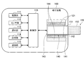
- FIG. 1 is a schematic diagram schematically showing an internal configuration example of a suction device.
- the suction device 100 includes a power supply unit 111, a sensor unit 112, a notification unit 113, a storage unit 114, a communication unit 115, a control unit 116, a heating unit 121, a holding unit 140, and a holding unit 140. Includes insulation 144.
- the power supply unit 111 stores electric power. Then, the power supply unit 111 supplies electric power to each component of the suction device 100 based on the control by the control unit 116.
- the power supply unit 111 may be composed of, for example, a rechargeable battery such as a lithium ion secondary battery.
- the sensor unit 112 acquires various information about the suction device 100.
- the sensor unit 112 is composed of a pressure sensor such as a microphone capacitor, a flow rate sensor, a temperature sensor, or the like, and acquires a value associated with suction by the user.
- the sensor unit 112 is configured by an input device such as a button or a switch that receives input of information from the user.
- the notification unit 113 notifies the user of the information.
- the notification unit 113 is composed of, for example, a light emitting device that emits light, a display device that displays an image, a sound output device that outputs sound, a vibrating vibration device, and the like.
- the storage unit 114 stores various information for the operation of the suction device 100.
- the storage unit 114 is composed of a non-volatile storage medium such as a flash memory.
- the communication unit 115 is a communication interface capable of performing communication conforming to any wired or wireless communication standard.
- a communication standard for example, Wi-Fi (registered trademark), Bluetooth (registered trademark), or the like can be adopted.
- the control unit 116 functions as an arithmetic processing device and a control device, and controls the overall operation in the suction device 100 according to various programs.
- the control unit 116 is realized by, for example, an electronic circuit such as a CPU (Central Processing Unit) and a microprocessor.
- the holding portion 140 has an internal space 141, and holds the stick-type base material 150 while accommodating a part of the stick-type base material 150 in the internal space 141.
- the holding portion 140 has an opening 142 that communicates the internal space 141 to the outside, and holds the stick-type base material 150 inserted into the internal space 141 from the opening 142.
- the holding portion 140 is a tubular body having an opening 142 and a bottom portion 143 as a bottom surface, and defines a columnar internal space 141.
- the holding portion 140 also has a function of defining a flow path of air supplied to the stick-type base material 150.
- An air inflow hole which is an inlet for air to such a flow path, is arranged, for example, at the bottom 143.
- the air outflow hole which is an outlet for air from such a flow path, is an opening 142.
- the stick-type base material 150 includes a base material portion 151 and a mouthpiece portion 152.
- the base material portion 151 contains an aerosol source.
- the aerosol source is not limited to a liquid, but may be a solid.
- the heating unit 121 heats the aerosol source to atomize the aerosol source and generate an aerosol.
- the heating unit 121 is formed in a film shape and is arranged so as to cover the outer periphery of the holding unit 140. Then, when the heating unit 121 generates heat, the base material portion 151 of the stick-type base material 150 is heated from the outer periphery to generate an aerosol.
- the heating unit 121 generates heat when power is supplied from the power supply unit 111.
- power may be supplied when the sensor unit 112 detects that the user has started suction and / or that predetermined information has been input. Then, when it is detected by the sensor unit 112 that the user has finished the suction and / or that the predetermined information has been input, the power supply may be stopped.
- the heat insulating portion 144 prevents heat transfer from the heating portion 121 to other components.
- the heat insulating portion 144 is made of a vacuum heat insulating material, an airgel heat insulating material, or the like.
- suction device 100 has been described above.
- the configuration of the suction device 100 is not limited to the above, and various configurations exemplified below may be adopted.
- the heating portion 121 may be configured in a blade shape and may be arranged so as to project from the bottom portion 143 of the holding portion 140 to the internal space 141. In that case, the blade-shaped heating portion 121 is inserted into the base material portion 151 of the stick-type base material 150, and the base material portion 151 of the stick-type base material 150 is heated from the inside. As another example, the heating portion 121 may be arranged so as to cover the bottom portion 143 of the holding portion 140. Further, the heating unit 121 is a combination of two or more of a first heating unit that covers the outer periphery of the holding unit 140, a blade-shaped second heating unit, and a third heating unit that covers the bottom portion 143 of the holding unit 140. It may be configured as.
- the holding portion 140 may include an opening / closing mechanism such as a hinge that opens / closes a part of the outer shell forming the internal space 141. Then, the holding portion 140 may sandwich the stick-type base material 150 inserted in the internal space 141 by opening and closing the outer shell.
- the heating unit 121 may be provided at the sandwiched portion in the holding unit 140 and may be heated while pressing the stick-type base material 150.
- the means for atomizing the aerosol source is not limited to heating by the heating unit 121.
- the means for atomizing the aerosol source may be induction heating.
- FIG. 2 is an overall perspective view of the suction device 100 according to the present embodiment.
- FIG. 3 is an overall perspective view of the suction device according to the present embodiment in a state where the stick type base material 150 is held.
- the suction device 100 includes a top housing 11A, a bottom housing 11B, a cover 12, a switch 13, a lid 14, a vent 15, and a cap 16.
- the top housing 11A and the bottom housing 11B are connected to each other to form the outermost outer housing 11 of the suction device 100.
- the outer housing 11 is sized to fit in the user's hand. When the user uses the suction device 100, the suction device 100 can be held by hand to suck the flavor.
- the top housing 11A has an opening (not shown), and the cover 12 is coupled to the top housing 11A so as to close the opening.
- the cover 12 has an opening 142 into which the stick-type substrate 150 can be inserted.
- the lid portion 14 is configured to open and close the opening 142 of the cover 12.
- the lid portion 14 is attached to the cover 12 and is configured to be movable along the surface of the cover 12 between the first position for closing the opening 142 and the second position for opening the opening 142.
- the cover Thereby, the lid portion 14 can allow or restrict access of the stick-type base material 150 to the inside of the suction device 100 (internal space 141 shown in FIG. 1).
- the state in which the lid portion 14 is in the second position and the lid portion 14 opens the opening 142 is also referred to hereinafter as an open state.
- the state in which the lid portion 14 is in the first position and the lid portion 14 closes the opening 142 is also referred to hereinafter as a closed state.
- the switch 13 is used to switch the operation of the suction device 100 on and off.
- the user operates the switch 13 with the stick-type base material 150 inserted into the internal space 141 from the opening 142, so that power is supplied to the heating unit 121 from the power supply unit 111, and the stick The mold base material 150 can be heated without burning.
- the stick-type base material 150 is heated, an aerosol is generated from the aerosol source contained in the stick-type base material 150, and the flavor of the flavor source is incorporated into the aerosol.
- the user can suck the aerosol containing the flavor by sucking the portion of the stick-type base material 150 protruding from the suction device 100 (the portion shown in FIG. 3, that is, the mouthpiece portion 152).
- the vent 15 is a vent for introducing air into the internal space 141.
- the air taken into the inside of the suction device 100 from the vent 15 is introduced into the internal space 141 through, for example, an air inflow hole formed in the bottom 143 of the holding portion 140.
- the cap 16 is detachably configured on the bottom housing 11B. By attaching the cap 16 to the bottom housing 11B, a vent 15 is formed between the bottom housing 11B and the cap 16.
- the cap 16 may have, for example, through holes or notches (not shown).
- the longitudinal direction of the suction device 100 means the direction in which the stick-type base material 150 is inserted into the opening 142. Further, in the suction device 100 of the present specification, the side where the fluid such as air flows in (for example, the vent 15 side) is the upstream side, and the side where the fluid flows out (for example, the opening 142 side) is the downstream side.
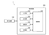
- FIG. 4 is a diagram showing an example of the configuration of the system 1 according to the present embodiment. As shown in FIG. 4, the system 1 includes a suction device 100 and a terminal device 200.
- the suction device 100 uses a base material containing an aerosol source to generate an aerosol that is sucked by the user.
- the heating unit 121 heats a substrate containing an aerosol source to generate an aerosol.
- the stick-type base material 150 is an example of the base material in the present embodiment.
- the terminal device 200 is a device used by the user of the suction device 100.
- the terminal device 200 is composed of an arbitrary information processing device such as a smartphone, a tablet terminal, or a wearable device.
- the terminal device 200 includes an input unit 210, an output unit 220, a communication unit 230, a storage unit 240, and a control unit 250.
- the input unit 210 has a function of accepting input of various information.
- the input unit 210 may include an input device that receives input of information from the user. Examples of the input device include a button, a keyboard, a touch panel, a microphone, and the like.
- the input unit 210 may include various sensors such as an image sensor.
- the output unit 220 has a function of outputting information.
- the output unit 220 may include an output device that outputs information to the user.
- Examples of the output device include a display device that displays information, a light emitting device that emits light, a vibrating vibration device, and a sound output device that outputs sound.
- An example of a display device is a display.
- An example of a light emitting device is an LED (Light Emitting Diode).
- An example of a vibrating device is an eccentric motor.
- An example of a sound output device is a speaker.
- the output unit 220 notifies the user of the information by outputting the information input from the control unit 250.
- the communication unit 230 is a communication interface for transmitting and receiving information between the terminal device 200 and another device.
- the communication unit 230 performs communication conforming to any wired or wireless communication standard.
- a communication standard for example, a wireless LAN (Local Area Network), a wired LAN, Wi-Fi (registered trademark), Bluetooth (registered trademark), or the like can be adopted.
- the storage unit 240 stores various information for the operation of the terminal device 200.
- the storage unit 240 is composed of a non-volatile storage medium such as a flash memory.
- the control unit 250 functions as an arithmetic processing device or a control device, and controls the overall operation in the terminal device 200 according to various programs.
- the control unit 250 is realized by, for example, an electronic circuit such as a CPU (Central Processing Unit) or a microprocessor.
- the control unit 250 may include a ROM (Read Only Memory) for storing a program to be used, calculation parameters, and the like, and a RAM (Random Access Memory) for temporarily storing parameters and the like that change as appropriate.
- the terminal device 200 executes various processes based on the control by the control unit 250.
- Processing of information input by the input unit 210, output of information by the output unit 220, transmission / reception of information by the communication unit 230, and storage and reading of information by the storage unit 240 are examples of processing controlled by the control unit 250.
- Other processes executed by the terminal device 200, such as input of information to each component and processing based on the information output from each component, are also controlled by the control unit 250.
- the function of the control unit 250 may be realized by using an application.
- the application may be pre-installed or downloaded. Further, the function of the control unit 250 may be realized by PWA (Progressive Web Apps).
- the suction device 100 can communicate with other devices.
- the communication link used for communication between the suction device 100 and another device may be wireless or wired. In the present specification, it is assumed that the communication link is wireless.
- the suction device 100 establishes a connection with another paired device and transmits / receives information. Pairing is a process of exchanging and storing information between two devices.
- An example of the exchanged information is the identification information of the other party such as SSID (Service Set Identifier) and the information related to the encryption key used for encrypting the transmitted / received information.
- SSID Service Set Identifier
- the suction device 100 and the terminal device 200 first perform pairing, and then transmit and receive information. It is desirable that the wireless communication standard used for wireless communication between the suction device 100 and the terminal device 200 is a short-range wireless communication standard such as Bluetooth. In that case, the suction device 100 and the terminal device 200 can establish a connection and communicate when they are located within a range where short-range wireless communication is possible. In the following, it is assumed that the suction device 100 and the terminal device 200 communicate with each other in accordance with BLE (Bluetooth Low Energy (registered trademark)).
- BLE Bluetooth Low Energy
- the connection between the suction device 100 and the terminal device 200 may be established when certain conditions are met.
- One example of the predetermined condition is that the state of the lid portion 14 has changed to the open state.
- Another example of the predetermined condition is that the charging of the power supply unit 111 has started.
- the suction device 100 is connected to an external power source via, for example, USB (Universal Serial Bus) or the like, the suction device 100 starts charging the power supply unit 111.
- USB Universal Serial Bus
- the connection between the suction device 100 and the terminal device 200 may be disconnected when a predetermined condition is satisfied.
- a predetermined condition is that the state of the lid portion 14 has changed to the closed state.
- Another example of the predetermined condition is that the charging of the power supply unit 111 is completed.
- the suction device 100 ends charging of the power supply unit 111, for example, when the connection with the external power supply is disconnected.
- the suction device 100 is, for example, when any of these predetermined conditions is satisfied, and when the operation by the user is not detected for a predetermined time or more and the information is not transmitted / received, the suction device 100 and the terminal device 200 are used. Disconnect.
- the suction device 100 operates based on the operation setting.
- the operation setting is information for setting the operation of the suction device 100.
- the suction device 100 may store one or more operation settings. Of one or more operation settings stored in the suction device 100, the operation setting used by the suction device 100 is also referred to as an operation setting to be used. That is, the suction device 100 operates based on the operation setting of the object to be used. More specifically, the control unit 116 controls the operation of each component of the suction device 100 including the heating unit 121 based on the operation setting of the object to be used. An example of the operation setting will be described below.
- the operation setting may include a heating profile.
- the control unit 116 controls the operation of the heating unit 121 based on the heating profile.
- the heating profile is information indicating a time-series transition of a target value of a value measured with respect to the heating unit 121 (hereinafter, also referred to as an actually measured value).
- the control unit 116 controls the operation of the heating unit 121 so that the time-series transition of the measured value measured with respect to the heating unit 121 becomes the same as the time-series transition of the target value specified in the heating profile. This produces the aerosol as planned by the heating profile.
- the heating profile is typically designed to optimize the flavor the user tastes when the user inhales the aerosol produced from the stick-type substrate 150. Therefore, by controlling the operation of the heating unit 121 based on the heating profile, the flavor to be tasted by the user can be optimized.
- the measured value may be the temperature of the heating unit 121.
- the heating profile is information that defines the time-series transition of the target temperature, which is the target value of the temperature of the heating unit 121.
- the control unit 116 controls the temperature of the heating unit 121 so that the time-series transition of the actual temperature (hereinafter, also referred to as the actual temperature) of the heating unit 121 becomes the same as the time-series transition of the target temperature specified in the heating profile. To control. This makes it possible to optimize the flavor that the user tastes.
- the heating profile includes one or more combinations of the elapsed time from the start of heating and the target temperature to be reached in the elapsed time. Then, the control unit 116 controls the temperature of the heating unit 121 based on the difference between the target temperature in the heating profile corresponding to the elapsed time from the start of the current heating and the current actual temperature.
- the temperature control of the heating unit 121 can be realized by, for example, a known feedback control. Specifically, the control unit 116 supplies the electric power from the power supply unit 111 to the heating unit 121 in the form of a pulse by pulse width modulation (PWM) or pulse frequency modulation (PFM). In that case, the control unit 116 can control the temperature of the heating unit 121 by adjusting the duty ratio of the power pulse.
- PWM pulse width modulation
- PFM pulse frequency modulation
- the control unit 116 may control the electric power supplied to the heating unit 121, for example, the duty ratio described above, based on the difference between the actual temperature and the target temperature.
- the feedback control may be, for example, PID control (Proportional-Integral-Differential Controller).
- the control unit 116 may perform simple ON-OFF control. For example, the control unit 116 executes heating by the heating unit 121 until the actual temperature reaches the target temperature, stops heating by the heating unit 121 when the actual temperature reaches the target temperature, and the actual temperature is lower than the target temperature. Then, the heating by the heating unit 121 may be executed again.
- the temperature of the heating unit 121 can be quantified by, for example, measuring or estimating the resistance value (more accurately, the electric resistance value) of the heating unit 121 (more accurately, the heat generating resistor constituting the heating unit 121). .. This is because the resistance value of the heat generation resistor changes according to the temperature.
- the resistance value of the heat-generating resistor can be estimated, for example, by measuring the amount of voltage drop in the heat-generating resistor.
- the amount of voltage drop in the heat-generating resistor can be measured by a voltage sensor that measures the potential difference applied to the heat-generating resistor.
- the temperature of the heating unit 121 can be measured by a temperature sensor installed near the heating unit 121.
- the time interval from the start to the end of the process of producing an aerosol using the stick-type base material 150 is also referred to as a heating session below. ..
- the beginning of the heating session is when heating based on the heating profile begins.
- the end of the heating session is when a sufficient amount of aerosol is no longer produced.
- the heating session consists of a preheating period in the first half and a puffable period in the second half.
- the puffable period is the period during which a sufficient amount of aerosol is expected to be generated.
- the preheating period is the period from the start of heating to the start of the puffable period.
- the heating performed during the preheating period is also referred to as preheating.
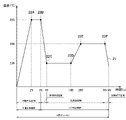
- FIG. 5 is a graph showing an example of the time-series transition of the actual temperature of the heating unit 121 operated based on the heating profile shown in Table 1.
- the horizontal axis of this graph is time (seconds).
- the vertical axis of this graph is the temperature of the heating unit 121.
- the line 21 in this graph shows the time-series transition of the actual temperature of the heating unit 121.
- points 22 (22A to 22F) in this graph indicate the target temperature specified in the heating profile.
- the actual temperature of the heating unit 121 changes in the same manner as the time-series transition of the target temperature defined in the heating profile.
- the heating profile initially includes the initial temperature rise section.
- the initial temperature rise section is a time section included at the beginning of the heating profile, and is a section in which the target temperature set at the final stage is higher than the initial temperature.
- the initial temperature is a temperature assumed as the temperature of the heating unit 121 before the start of heating.
- An example of the initial temperature is an arbitrary temperature such as 0 ° C.
- Another example of the initial temperature is the temperature corresponding to the air temperature.
- the actual temperature of the heating unit 121 reaches 295 ° C. 25 seconds after the start of heating and is maintained at 295 ° C. until 35 seconds after the start of heating. ing.
- the temperature of the stick-type base material 150 reaches the temperature at which a sufficient amount of aerosol is generated.
- the temperature of the stick-type base material 150 reaches the temperature at which a sufficient amount of aerosol is generated.
- the heating profile then includes an intermediate temperature drop section.
- the intermediate temperature drop section is a time section after the initial temperature rise section, in which the target temperature set at the end is lower than the target temperature set at the end of the initial temperature rise section.
- the actual temperature of the heating unit 121 drops from 295 ° C. to 230 ° C. from 35 seconds to 45 seconds after the start of heating according to the target temperature set in the intermediate temperature drop section.
- the power supply to the heating unit 121 may be stopped. Even in that case, the residual heat of the heating unit 121 and the stick-type base material 150 produces a sufficient amount of aerosol.
- the heating unit 121 if the heating unit 121 is maintained at a high temperature, the aerosol source contained in the stick-type base material 150 is rapidly consumed, which may cause inconveniences such as the flavor being tasted by the user being too strong. In that respect, it is possible to avoid such inconvenience and improve the quality of the user's puff experience by providing an intermediate temperature drop section in the middle.
- the heating profile then includes the reheating section.
- the re-heating section is a time section after the intermediate temperature drop section, in which the target temperature set at the end is higher than the target temperature set at the end of the intermediate temperature drop section.
- the actual temperature of the heating unit 121 gradually increases from 230 ° C. to 260 ° C. from 45 seconds to 355 seconds after the start of heating according to the target temperature set in the reheating section. ing. If the temperature of the heating unit 121 is continuously lowered, the temperature of the stick-type base material 150 is also lowered, so that the amount of aerosol produced is reduced and the flavor tasted by the user may be deteriorated. In that respect, by lowering the temperature and then raising the temperature again, it is possible to prevent deterioration of the flavor tasted by the user even in the latter half of the heating session.
- the heating profile finally includes the heating end section.
- the heating end section is a time section after the reheating section and is a time section in which heating is not performed.
- the target temperature does not have to be set.
- the actual temperature of the heating unit 121 has dropped after 355 seconds from the start of heating. After 355 seconds from the start of heating, the power supply to the heating unit 121 may be terminated. Even in that case, for a while, the residual heat of the heating unit 121 and the stick-type base material 150 produces a sufficient amount of aerosol.
- the puffable period that is, the heating session ends.
- the user may be notified when the puffable period starts and ends. Further, the user may be notified of the timing (for example, the timing at which the power supply to the heating unit 121 ends) before the end of the puffable period. In that case, the user can puff during the puffable period with reference to the notification.
- the timing for example, the timing at which the power supply to the heating unit 121 ends
- the measured value may be the resistance value of the heating unit 121. This point will be described below.
- the temperature of the heating unit 121 is synonymous with the resistance value of the heating unit 121. Therefore, the target temperature of the heating unit 121 can also be indicated by the resistance value of the heating unit 121. That is, the parameter in the heating profile may be the resistance value of the heating unit 121 corresponding to the target temperature. In that case, the heating profile is information that defines the time-series transition of the target resistance value, which is the target value of the resistance value of the heating unit 121.
- the suction device 100 controls the resistance value of the heating unit 121 so that the time-series transition of the actual resistance value of the heating unit 121 becomes the same as the time-series transition of the target resistance value defined in the heating profile.
- the resistance value control of the heating unit 121 can be realized by, for example, a known feedback control.
- the control unit 116 supplies the electric power from the power supply unit 111 to the heating unit 121 in the form of a pulse by pulse width modulation (PWM) or pulse frequency modulation (PFM).
- PWM pulse width modulation
- PFM pulse frequency modulation
- the control unit 116 can control the resistance value of the heating unit 121 by adjusting the duty ratio of the power pulse. According to such a configuration, it is possible to change the actual temperature of the heating unit 121 in the same manner as when the heating profile defines the time-series transition of the target temperature.
- the temperature of the heating unit 121 has a corresponding relationship with the resistance value of the heating unit 121, but the resistance value corresponding to the temperature of the heating unit 121 depends on the characteristics of the heating unit 121 and the environmental temperature. Therefore, if the characteristics of the heating unit 121 or the environmental temperature are different, the target resistance value corresponding to the target temperature will be different even if the target temperature is the same.
- the measured value is the resistance value of the heating unit 121 and the target value in the heating profile is the target resistance value will be mainly described.
- the operation setting may include a high temperature protection threshold.
- the high temperature protection threshold is a threshold used to prevent inconvenience caused by high temperature, which will be described later.
- the threshold value for high temperature protection will be described.
- the suction device 100 includes a first temperature detecting unit that detects the temperature as a sensor unit 112.
- An example of the first temperature detection unit is a thermistor.
- the thermistor is a resistor whose electric resistance value changes according to a temperature change, and can detect the temperature based on the electric resistance value.
- the first temperature detection unit detects the temperature of a portion of the suction device 100 that is expected to come into contact with the user when sucking the aerosol.
- the first temperature detecting unit is provided in the vicinity of the outer housing 11 and detects the temperature of the outer housing 11. In that case, the temperature felt by the user when the suction device 100 is held and used by the user can be detected.
- control unit 116 controls the operation of the heating unit 121 depending on whether or not the temperature detected by the first temperature detection unit exceeds the threshold value for high temperature protection. According to such a configuration, it is possible to realize heating according to the temperature felt by the user.
- control unit 116 prohibits power supply to the heating unit 121 when the temperature detected by the first temperature detection unit exceeds the threshold value for high temperature protection. Therefore, if the heating by the heating unit 121 is being executed, the heating is interrupted. Further, the heating is not started before the heating by the heating unit 121 is executed. According to such a configuration, for example, heating can be interrupted before the outer housing 11 becomes excessively hot, or heating can be prevented from starting when it is expected that the outer housing 11 becomes excessively hot. Therefore, it is possible to prevent inconveniences caused by high temperatures such as burns of the user.
- control unit 116 permits power supply to the heating unit 121 when the temperature detected by the first temperature detection unit is equal to or lower than the threshold value for high temperature protection. Therefore, if the heating by the heating unit 121 is being executed, the heating is continued. Further, before the heating by the heating unit 121 is executed, the heating is started in response to the pressing of the switch 13. According to such a configuration, it is possible to perform heating to deliver the aerosol to the user within a range that can prevent the inconvenience caused by the high temperature.
- the operation setting may include a plurality of high temperature protection thresholds set for each elapsed time from the start of heating.
- the control unit 116 determines whether or not the temperature detected by the first temperature detection unit exceeds the high temperature protection threshold value corresponding to the elapsed time from the start of heating among the plurality of high temperature protection threshold values.
- the operation of the heating unit 121 is controlled.
- the operation setting is the high temperature protection threshold TH A , which should be used after TA seconds have passed since the heating based on the heating profile was started, and the high temperature protection threshold TH B , which should be used after TB seconds have passed . including.
- control unit 116 is based on the high temperature protection threshold TH A after TA seconds have elapsed from the start of heating based on the heating profile, and based on the high temperature protection threshold TH B after TB seconds have elapsed.
- the operation of the heating unit 121 is controlled.
- the temperature of the heating unit 121 changes with the passage of time from the start of heating based on the heating profile, and the temperature assumed to be detected by the first temperature detection unit may also change accordingly. In this respect, according to such a configuration, it is possible to more reliably prevent inconvenience caused by high temperature.
- the high temperature protection threshold may be different for each heating profile. That is, a high temperature protection threshold may be set for each heating profile.
- the temperature assumed to be detected by the first temperature detector may differ for each heating profile. In this respect, according to such a configuration, it is possible to more reliably prevent inconvenience caused by high temperature.
- the operation setting may include the puff detection standard.
- the puff detection criterion is a detection criterion used to detect that the aerosol has been aspirated by the user.
- the puff detection standard will be described.
- the suction device 100 includes a second temperature detection unit as a sensor unit 112 that detects a temperature that changes when the aerosol is sucked by the user.
- An example of the second temperature detector is a thermistor.
- the second temperature detection unit is arranged near the flow path of the aerosol, for example, near the holding unit 140.
- the puff detection standard is a standard for detecting that the temperature detected by the second temperature detection unit has decreased due to the puff.
- the puff detection standard includes the puff detection threshold.
- the puff detection threshold is a threshold used for puff detection.
- the control unit 116 detects that the aerosol has been sucked by the user by comparing the value corresponding to the temperature detected by the second temperature detection unit with the puff detection threshold value.
- An example of a value corresponding to the temperature detected by the second temperature detection unit is an output value obtained by inputting the temperature detected by the second temperature detection unit to the filter. Such an output value corresponds to the amount of decrease in temperature detected by the second temperature detection unit.
- An example of a filter is a digital filter such as an FIR (Finite Impulse Response) filter and an IIR (Infinite Impulse Response) filter.
- control unit 116 detects that the puff has been performed when the output value obtained by inputting the temperature detected by the second temperature detection unit to the filter exceeds the puff detection threshold value. May be good. According to such a configuration, it is possible to detect the puff based on the fact that the temperature detected by the second temperature detecting unit decreases with the puff.
- the puff detection criterion may further include the puff detection filter coefficient in addition to the puff detection threshold.
- the puff detection filter coefficient is the coefficient of the filter used for puff detection.
- the control unit 116 compares the output value obtained by inputting the temperature detected by the second temperature detection unit to the filter to which the puff detection filter coefficient is applied and the puff detection threshold value. Detects that the aerosol has been aspirated by the user. For example, when the output value obtained by inputting the temperature detected by the second temperature detection unit to the filter to which the puff detection filter coefficient is applied exceeds the puff detection threshold value, the control unit 116 causes the puff. Detect what has been done. By using a filter to which an appropriate puff detection filter coefficient is applied, it is possible to improve the puff detection accuracy.
- the puff detection criterion may include a plurality of puff detection thresholds set for each elapsed time from the start of heating.
- the control unit 116 detects that the aerosol has been sucked by the user based on the puff detection threshold value corresponding to the elapsed time from the start of heating among the plurality of puff detection threshold values.
- the puff detection criteria are the puff detection threshold TH A that should be used after TA seconds have passed since the start of heating based on the heating profile, and the puff detection threshold TH B that should be used after TB seconds have passed . include.
- the suction device 100 is based on the puff detection threshold TH A after TA seconds have elapsed from the start of heating based on the heating profile, and based on the puff detection threshold TH B after TB seconds have elapsed. Detect puffs.
- the temperature of the heating unit 121 changes with the passage of time from the start of heating based on the heating profile, and the temperature detected by the second temperature detection unit may change accordingly. In this respect, according to such a configuration, it is possible to improve the detection accuracy of the puff.
- the puff detection criteria may differ for each heating profile. That is, a puff detection standard may be set for each heating profile. Considering that the temperature detected by the second temperature detection unit may differ for each heating profile, such a configuration makes it possible to improve the detection accuracy of the puff.
- the operation setting may include a threshold value for determining low battery level.
- the threshold value for determining the remaining battery level is a threshold value used for detecting a decrease in the remaining amount of electric power stored in the power supply unit 111.
- the threshold value for determining the remaining battery level will be described.
- the threshold value for determining the remaining battery level is set as a value equal to or greater than the amount of electric power used for the heating unit 121 to heat the stick-type base material 150 to generate an aerosol a specified number of times.
- the process of heating the stick-type base material 150 to generate an aerosol is executed once for one stick-type base material 150, and the specified number of times corresponds to the number of stick-type base materials 150 to be consumed. Consumption here refers to heating the stick-type substrate 150 based on the heating profile from start to finish without interruption. That is, the threshold value for determining the decrease in the remaining battery level is a value equal to or greater than the amount of electric power used to consume the specified number of stick-type base materials 150.
- the suction device 100 can determine whether or not the power supply unit 111 has a sufficient remaining amount of electric power for consuming a specified number of stick-type base materials 150.
- the specified number of times may be 1. In that case, the suction device 100 can determine whether or not it has the remaining power used to consume one stick-type substrate 150.
- the control unit 116 compares the remaining power of the power supply unit 111 with the threshold value for determining the decrease in the remaining battery level, and controls the operation of the suction device 100 based on the comparison result.
- the control unit 116 may prohibit heating by the heating unit 121 when the remaining electric power of the power supply unit 111 falls below the threshold value for determining the decrease in the battery remaining amount. According to such a configuration, it is possible to avoid a situation in which the stick-type base material 150 is halfway consumed due to insufficient power remaining.
- the remaining power of the power supply unit 111 is measured by an arbitrary method.
- the control unit 116 may measure the remaining power of the power supply unit 111 based on the voltage of the power supply unit 111.
- the control unit 116 may measure the remaining power of the power supply unit 111 based on the SOC (State of Charge) or RC (Residual charge) of the battery fuel gauge.
- the threshold value for determining the remaining battery level may be different for each heating profile. That is, a threshold value for determining the remaining battery level may be set for each heating profile.
- the amount of power consumed to consume one stick-type substrate 150 may differ for each heating profile. Therefore, with such a configuration, it is possible to more accurately determine the decrease in the remaining power of the power supply unit 111.
- the suction device 100 can switch the operation settings of the object to be used.
- Suitable operation settings may differ for each type of stick-type base material 150.
- suitable operation settings may differ depending on the type and composition of the aerosol source and the flavor source contained in the stick-type base material 150. In this respect, it is possible to improve the quality of the user experience by switching the operation setting of the object to be used according to the type of the stick type base material 150.
- the operation setting according to the user's preference may be used as the operation setting to be used.
- which of the operation setting in which the amount of aerosol generated per unit time is large and the operation setting in which the amount of aerosol generated per unit time is small may be preferred may differ from user to user.
- the quality of the user experience can be improved by switching the operation setting of the usage target according to the user's preference.
- the switching method is arbitrary.
- the suction device 100 may switch the operation setting of the object to be used based on the user operation for the suction device 100.
- the suction device 100 may switch the operation setting of the object to be used based on the signal received from the terminal device 200.
- the suction device 100 may identify the inserted stick-type base material 150 and switch the operation setting of the object to be used based on the identification result.
- the identification of the stick-type base material 150 is performed, for example, by recognizing an image of a two-dimensional code or the like given to the stick-type base material 150.
- the suction device 100 transmits information indicating the operation setting stored in the storage unit 114. Such information is received by the terminal device 200. As a result, the terminal device 200 can grasp the operation settings stored in the suction device 100.
- the terminal device 200 may transmit information requesting transmission of information indicating the operation setting. Upon receiving the information requesting transmission of the information indicating the operation setting, the suction device 100 transmits the information indicating the operation setting requested to be transmitted in the received information. According to such a configuration, the terminal device 200 can acquire information indicating the operation setting from the suction device 100, if necessary.
- the suction device 100 may transmit identification information corresponding to the operation setting as information indicating the operation setting.
- An example of the identification information is a number corresponding to the operation setting. According to such a configuration, it is possible to reduce the amount of communication as compared with the case where the operation setting itself is transmitted.
- the terminal device 200 When the terminal device 200 receives the information indicating the operation setting stored in the suction device 100, the terminal device 200 performs a process based on the received information. As an example, the terminal device 200 outputs information indicating the received operation setting. According to such a configuration, the user can easily grasp the operation setting stored in the suction device 100.
- the terminal device 200 outputs information indicating one or more operation settings that can be used by the suction device 100 as the operation settings to be used.
- information indicating one or more operation settings that can be used by the suction device 100 as the operation settings to be used is information indicating the operation settings already stored in the suction device 100.
- Another example of information indicating one or more operation settings that the suction device 100 can use as the operation setting to be used is an operation that can be downloaded from the suction device 100 (for example, transmission from the terminal device 200 to the suction device 100).
- Information indicating the setting is an example of UI (User Interface) will be described with reference to FIG.
- FIG. 6 is a diagram showing an example of a display screen displayed by the terminal device 200 according to the present embodiment. It is assumed that the suction device 100 can use the "operation setting 1", “operation setting 2", and “operation setting 3" as the operation setting to be used. Therefore, as shown in FIG. 6, on the display screen 30A, icons 31A to 31C indicating three operation settings are displayed as information indicating one or more operation settings that can be used as the operation settings of the suction device 100. Has been done. According to such a configuration, the user can easily grasp that the suction device 100 can use the "operation setting 1", “operation setting 2", and "operation setting 3".
- the terminal device 200 may store in the storage unit 240 information indicating one or more operation settings that can be used by the suction device 100 as the operation settings to be used. In that case, the terminal device 200 outputs information stored in the storage unit 240 indicating one or more operation settings that can be used by the suction device 100 as the operation settings to be used. For example, each time the operation setting is downloaded to the suction device 100, the terminal device 200 stores which operation setting is downloaded to the suction device 100, and outputs information indicating the downloaded operation setting. According to such a configuration, even if the terminal device 200 does not communicate with the suction device 100, the terminal device 200 outputs information indicating one or more operation settings that can be used as the operation settings to be used by the suction device 100. It is possible.
- the terminal device 200 may acquire and output information indicating all the operation settings stored in the suction device 100 from the suction device 100. In that case, the terminal device 200 transmits information requesting transmission of information indicating all the operation settings stored in the suction device. Upon receiving such information, the suction device 100 transmits information indicating all the operation settings stored in the storage unit 114. Then, the terminal device 200 outputs information indicating all the operation settings stored in the received suction device 100 as information indicating one or more operation settings that can be used as the operation settings of the suction device 100. .. Considering that the suction device 100 can download the operation settings from a device other than the terminal device 200, such a configuration enables the terminal device 200 to output accurate information.
- the terminal device 200 outputs information indicating the operation setting being used by the suction device 100, that is, the operation setting of the target to be used.
- a UI example will be described with reference to FIG. 7.
- FIG. 7 is a diagram showing an example of a display screen displayed by the terminal device 200 according to the present embodiment. It is assumed that the suction device 100 can use the "operation setting 1", “operation setting 2", or "operation setting 3" as the operation setting to be used. Therefore, as shown in FIG. 7, on the display screen 30B, icons 31A to 31C indicating three operation settings are displayed as information indicating one or more operation settings that can be used as the operation settings of the suction device 100. Has been done. Further, when the operation setting of the object to be used of the suction device 100 is "operation setting 1", the terminal device 200 focuses on the icon 31A corresponding to the "operation setting 1" as shown in FIG. 7. With such a configuration, the user can easily grasp that the suction device 100 operates based on the "operation setting 1".
- the terminal device 200 may store information indicating the operation setting of the object to be used in the suction device 100 in the storage unit 240. In that case, the terminal device 200 outputs the information stored in the storage unit 240 indicating the operation setting of the object to be used in the suction device 100. For example, as will be described later, the terminal device 200 may transmit a request for switching the operation setting of the target to be used to the suction device 100, and based on the transmission history, provides information indicating the operation setting of the target to be used in the suction device 100. It may be output. According to such a configuration, the terminal device 200 can output information indicating the operation setting of the object to be used in the suction device 100 even when the terminal device 200 is not communicating with the suction device 100.
- the terminal device 200 may acquire information indicating the operation setting of the object to be used in the suction device 100 from the suction device 100 and output it. In that case, the terminal device 200 transmits the information requesting the transmission of the information indicating the operation setting of the object to be used in the suction device 100. Upon receiving such information, the suction device 100 transmits information indicating the operation setting of the object to be used. Then, the terminal device 200 outputs information indicating the operation setting of the object to be used in the received suction device 100. Considering that the suction device 100 can switch the operation setting of the object to be used by a factor other than the instruction from the terminal device 200, the terminal device 200 can output accurate information by such a configuration.
- the suction device 100 can switch the operation setting of the target to be used from the operation settings stored in the storage unit 114.
- the suction device 100 can switch the operation setting to be used to an operation setting suitable for the type of the stick-type base material 150, an operation setting according to the user's preference, or the like based on an instruction from the terminal device 200. be. With such a configuration, it is possible to improve the quality of the user experience.
- the terminal device 200 accepts a user operation for selecting an operation setting of a switching destination. For example, the terminal device 200 sets an operation setting other than the current operation setting of the use target as an operation setting of the switching destination on the display screen displaying information indicating one or more operation settings that can be used as the operation setting of the use target. Accepts user operations to select.
- the terminal device 200 accepts a user operation for selecting the icon 31B or 31C.
- the display screen 30B may be displayed on a touch panel that also serves as an input unit 210 and an output unit 220. In that case, the user can select the operation setting of the switching destination by touching the icon 31B or 31C.
- the terminal device 200 When the terminal device 200 receives a user operation for selecting the operation setting of the switching destination, the terminal device 200 transmits information instructing the operation setting of the selected switching destination to switch the operation setting to be used. For example, as information indicating the operation setting of the switching destination, identification information indicating the operation setting of the switching destination may be transmitted.
- the suction device 100 When the suction device 100 receives such information, the suction device 100 switches the operation setting of the object to be used to the operation setting of the switching destination instructed by the received information. After that, the suction device 100 operates based on the operation setting of the target to be used after switching. With such a configuration, the user can switch to a desired operation setting via the terminal device 200.
- the suction device 100 transmits information indicating that the switching of the operation setting of the target to be used is completed.
- the terminal device 200 receives such information, it outputs information indicating the operation setting of the target to be used after switching.
- the terminal device 200 displays information indicating the operation setting of the usage target after switching on the display screen displaying information indicating one or more operation settings that can be used as the operation setting of the usage target. For example, on the display screen 30B shown in FIG. 7, a UI example when a user operation for selecting the icon 31B corresponding to the “operation setting 2” is performed will be described with reference to FIG.
- FIG. 8 is a diagram showing an example of a display screen displayed by the terminal device 200 according to the present embodiment. It is assumed that the suction device 100 can use the "operation setting 1", “operation setting 2", and "operation setting 3" as the operation setting to be used. Therefore, as shown in FIG. 8, on the display screen 30C, icons 31A to 31C indicating three operation settings are displayed as information indicating one or more operation settings that can be used as the operation settings of the suction device 100. Has been done. Further, since the operation setting of the object to be used after switching is "operation setting 2", the terminal device 200 focuses on the icon 31B corresponding to the "operation setting 2" as shown in FIG. With such a configuration, the user can easily grasp that the operation setting to be used has been switched from “operation setting 1" to "operation setting 2".
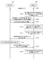
- FIG. 9 is a sequence diagram showing an example of a flow of processing for switching operation settings of an object to be used executed in the system 1 according to the present embodiment.
- the suction device 100 and the terminal device 200 are involved in this sequence.
- the suction device 100 and the terminal device 200 establish a connection (step S102).
- the terminal device 200 outputs information indicating one or more operation settings that can be used by the suction device 100 as the operation settings to be used (step S104). For example, the terminal device 200 outputs the display screen 30A shown in FIG.
- the terminal device 200 transmits information requesting transmission of information indicating the operation setting of the object to be used in the suction device 100 (step S106). Upon receiving such information, the suction device 100 transmits information indicating the operation setting of the object to be used (step S108). Then, when the terminal device 200 receives such information, it outputs information indicating the operation setting of the object to be used in the received suction device 100 (step S110). For example, the terminal device 200 outputs the display screen 30B shown in FIG. 7.
- the terminal device 200 accepts a user operation for selecting the operation setting of the switching destination (step S112). Then, the terminal device 200 transmits information instructing the selected operation setting of the switching destination to switch the operation setting to be used (step S114). Upon receiving such information, the suction device 100 switches the operation setting to be used to the operation setting instructed by the received information (step S116).
- the suction device 100 transmits information indicating that the switching of the operation setting of the object to be used is completed (step S118).
- the terminal device 200 Upon receiving such information, the terminal device 200 outputs information indicating the operation setting of the target to be used after switching (step S120). For example, the terminal device 200 outputs the display screen 30C shown in FIG.
- the terminal device 200 may transmit information indicating the operation settings and download new operation settings to the suction device 100.
- the terminal device 200 transmits information indicating the operation setting downloaded from the server to the suction device 100.
- the suction device 100 stores the operation setting indicated by the received information in the storage unit 114. After that, when the newly stored operation setting is selected as the operation setting to be used, the suction device 100 operates based on the newly stored operation setting. According to such a configuration, the user can download the desired operation setting to the suction device 100 via the terminal device 200.
- the information indicating the operation setting includes the target resistance value, the time, the first correction information, and the puff detection threshold value as the information for each step.
- a step is a time interval in which a heating profile is divided in the time direction.
- the information of a step is used when the elapsed time from the start of heating based on the heating profile is included in the step.
- the step is a time interval having a predetermined time length such as 10 seconds.
- step 00 is a time interval from the start of heating based on the heating profile to the elapse of 10 seconds. Therefore, the information in step 00 is used from the start of heating based on the heating profile until 10 seconds have elapsed.
- Step 19 is a time interval of 10 seconds immediately before the end of heating based on the heating profile. Therefore, the information in step 19 is used in the 10 seconds immediately before the end of heating based on the heating profile.
- the time length of the steps may be different for each step. Further, the number of steps is not limited to 20 from 00 to 19 shown in Table 2.
- the information indicating the operation setting includes the second correction information, the threshold value for high temperature protection, the puff detection filter coefficient, and the threshold value for determining the battery level decrease as other information. This information is used throughout the time interval during which heating is performed based on the heating profile.
- the information indicating the operation setting may be divided into a plurality of pieces and transmitted / received at different timings.
- step-by-step information consisting of a combination of a target resistance value, a time, a first correction information, and a puff detection threshold value may be transmitted and received at different timings.
- the information for each step and other information may be transmitted and received at different timings. According to such a configuration, it is possible to improve communication efficiency, such as facilitating retries when a transmission / reception error occurs.
- the information indicating the operation setting includes the target resistance value and time for each step.
- the time is the elapsed time from the start of heating, which should reach the target resistance value.
- the combination of the elapsed time from the start of heating and the target resistance value set for the elapsed time in all steps corresponds to the heating profile.
- the information indicating the operation setting may be divided and transmitted / received.
- the information indicating the heating profile may be transmitted and received divided in the time direction, such as step by step.
- the information indicating the heating profile divided in the time direction includes at least one combination of the elapsed time from the start of heating and the target resistance value set in the elapsed time. According to such a configuration, it is possible to improve the communication efficiency regarding the transmission / reception of the heating profile.
- the heating profile consisting of the combination of the target resistance value for each step and the time shown in Table 2 is the heating profile before correction (hereinafter, also referred to as the default heating profile).
- the default heating profile is corrected based on the first correction information, as will be described later.
- the default heating profile can be corrected based on the second correction information, as will be described later.
- the information indicating the operation setting includes the first correction information.
- the first correction information is an example of correction information for correcting the operation setting according to the individual difference of the heating unit 121.
- An example of individual differences in the heating unit 121 is the correspondence between the temperature and the resistance value.
- the control unit 116 may correct the operation setting based on the received first correction information. In that case, the control unit 116 controls the operation of the suction device 100 based on the corrected operation setting. According to such a configuration, the suction device 100 can operate according to the individual difference of the heating unit 121. Therefore, it is possible to improve the quality of the user's puff experience.
- the control unit 116 corrects the heating profile based on the first correction information. More specifically, the control unit 116 corrects the default heating profile based on the first correction information. Then, the control unit 116 controls the operation of the heating unit 121 based on the corrected heating profile. With such a configuration, heating can be performed based on the heating profile corrected to match the individual difference of the heating unit 121, so that it is possible to prevent inconvenience caused by the individual difference of the heating unit 121.
- One example of the inconvenience caused by the individual difference of the heating unit 121 is that the actual temperature of the heating unit 121 deviates from the target temperature.
- the information indicating the operation setting includes a plurality of first correction information associated with each of the plurality of target resistance values included in the heating profile. Then, the control unit 116 corrects each of the plurality of target value resistance values defined in the heating profile based on the associated first correction information. For example, the control unit 116 corrects the target resistance value included in the information in step 00 based on the first correction information included in the information in step 00.
- the first correction information may include an offset correction value which is a value used for offset correction. In that case, the control unit 116 adds the offset correction value to the target resistance value.
- the first correction information may include a gain correction value which is a value used for the gain correction. In that case, the control unit 116 multiplies the target resistance value by the gain correction value.
- the first correction information may include both an offset correction value and a gain correction value. According to such a configuration, the target resistance value can be appropriately corrected for each step.
- the first correction information may be different for each heating profile.
- the degree of inconvenience caused by individual differences in the heating unit 121 may differ depending on the heating profile. In this respect, such a configuration makes it possible to more reliably prevent inconveniences caused by individual differences in the heating unit 121.
- the suction device 100 transmits information indicating the individual difference of the heating unit 121 to the terminal device 200.
- the suction device 100 stores information indicating individual differences of the heating unit 121 at the time of manufacturing in the factory, and transmits the stored information to the terminal device 200.
- the terminal device 200 can grasp the individual difference of the heating unit 121.
- the terminal device 200 may transmit information requesting transmission of information indicating individual differences in the heating unit 121.
- the suction device 100 receives the information requesting the transmission of the information indicating the individual difference of the heating unit 121
- the suction device 100 transmits the information indicating the individual difference of the heating unit 121.
- the terminal device 200 can inquire of the suction device 100 about the individual difference of the heating unit 121 as a preliminary step for generating the first correction information.
- the terminal device 200 may store information indicating individual differences of the heating unit 121 received from the suction device 100, and then divert the stored information.
- the terminal device 200 When the terminal device 200 receives the information indicating the individual difference of the heating unit 121, the terminal device 200 generates the first correction information based on the received information indicating the individual difference of the heating unit 121. Then, the terminal device 200 transmits the generated first correction information.
- the suction device 100 receives the first correction information transmitted from the terminal device 200 in this way, and corrects the heating profile based on the received first correction information. According to such a configuration, it is possible to correct the heating profile based on the first correction information that matches the individual difference of the heating unit 121.
- the information indicating the operation setting includes the second correction information.
- the second correction information is an example of correction information for correcting the operation setting according to the deterioration of the heating unit 121.
- the deterioration of the heating unit 121 is the oxidation of the heating unit 121 that progresses each time the heating by the heating unit 121 is repeated.
- the control unit 116 may correct the operation setting based on the received second correction information. In that case, the control unit 116 controls the operation of the suction device 100 based on the corrected operation setting. According to such a configuration, the suction device 100 can operate according to the deterioration of the heating unit 121. Therefore, it is possible to improve the quality of the user's puff experience.
- control unit 116 may correct the heating profile based on the second correction information. More specifically, the control unit 116 may further correct the corrected heating profile based on the first correction information based on the second correction information. In that case, the control unit 116 controls the operation of the heating unit 121 based on the corrected heating profile. With such a configuration, heating can be performed based on a heating profile suitable for the degree of deterioration of the heating unit 121. This makes it possible to prevent inconvenience caused by deterioration of the heating unit 121.
- the control unit 116 integrates a history value indicating the history of heating executed by the heating unit 121 based on the execution of heating by the heating unit 121. As an example, the control unit 116 integrates a history value indicating the history of heating executed by the heating unit 121 every time heating by the heating unit 121 is executed. As another example, the control unit 116 integrates the history value indicating the history of the heating executed by the heating unit 121 every time the heating by the heating unit 121 is executed a plurality of times (for example, twice). As the number of heatings increases, the heating unit 121 oxidizes, and the resistance value of the heating unit 121 increases.
- the degree of oxidation of the heating unit 121 can be grasped from the historical value.
- the history value may be an integrated value of the number of times the heating unit 121 has been heated (hereinafter, also referred to as the number of times of heating). 1 may be added to the history value each time the heating based on the heating profile is performed once. That is, the history value may be an integrated value of the number of times the heating unit 121 has been heated based on the heating profile. During one heating based on the heating profile, short-time heating may be executed and stopped multiple times, and 1 is added to the history value each time the short-time heating is executed once. You may. In any case, the degree of oxidation of the heating unit 121 can be grasped from the number of heatings.
- the history value may be an integrated value of the time during which the heating unit 121 is heated (hereinafter, also referred to as heating time).
- heating time Each time the heating based on the heating profile is performed once, the time for one heating based on the heating profile may be added to the history value.
- the short-time heating While the heating based on the heating profile is performed once, the short-time heating may be executed and stopped a plurality of times, and the time required for the short-time heating may be accumulated in the history value. In any case, the degree of oxidation of the heating unit 121 can be grasped from the heating time.
- the control unit 116 corrects the heating profile based on the integrated history value and the second correction information. According to such a configuration, the heating profile is corrected according to the degree of oxidation of the heating unit 121 indicated by the historical value. Therefore, it is possible to prevent the occurrence of inconvenience caused by the oxidation of the heating unit 121.
- the control unit 116 corrects the target resistance value to be corrected, which is at least a part of the target resistance values specified in the heating profile, to a value corresponding to a higher temperature.
- the control unit 116 corrects the target resistance value to be corrected to a higher value.
- the actual temperature of the heating unit 121 is lower than the target temperature even if the resistance value of the heating unit 121 reaches the target resistance value. Become.
- the temperature drop due to the oxidation of the heating unit 121 is offset by the correction of the target resistance value, and the temperature control that does not change before and after oxidation is realized. It becomes possible to do. Therefore, it is possible to prevent the occurrence of inconvenience caused by the oxidation of the heating unit 121.
- the second correction information may include information indicating the target resistance value to be corrected.
- the control unit 116 corrects the target resistance value to be corrected, which is indicated by the second correction information. According to such a configuration, it is possible to prevent the inconvenience described below by limiting the target resistance value to be corrected.
- the target resistance value to be corrected includes the target resistance value corresponding to the lowest target temperature among the plurality of target resistance values specified in the heating profile.
- One of the inconveniences caused by the oxidation of the heating unit 121 is that the temperature of the stick-type base material 150 drops too much even during heating, and aerosol is not generated.
- the stage in which such an inconvenience is most likely to occur is the stage in which the target temperature corresponding to the target resistance value in the heating profile is the lowest. In this respect, according to such a configuration, it is possible to prevent the occurrence of such inconvenience.
- the target resistance value to be corrected does not include the target resistance value corresponding to the highest target temperature among the plurality of target resistance values specified in the heating profile. If the heating profile is corrected while the oxidation of the heating unit 121 is not progressing more than expected, the actual temperature may exceed the target temperature before correction and become excessively high, damaging the function of the suction device 100. There is.
- the stage in which such an inconvenience is most likely to occur is the stage in which the target temperature corresponding to the target resistance value in the heating profile is the highest. In this respect, according to such a configuration, it is possible to prevent such an inconvenience.
- the second correction information may include information indicating a threshold value.
- the control unit 116 corrects the heating profile when the historical value exceeds the threshold value indicated by the second correction information.
- the control unit 116 may correct the heating profile when the number of heating times exceeds 1000 times.
- the control unit 116 may correct the heating profile every time the heating time exceeds 100,000 seconds. According to such a configuration, since the correction frequency of the heating profile is suppressed, it is possible to reduce the processing load of the control unit 116.
- the second correction information may include information indicating a correction method of the heating profile. In that case, the control unit 116 corrects the heating profile based on the correction method indicated by the second correction information.
- the second correction information may include a value to be added to the target resistance value. In that case, the control unit 116 adds the value to be added to the target resistance value included in the second correction information to the target resistance value before correction. According to such a configuration, it is possible to appropriately correct the target resistance value.
- the second correction information may be different for each heating profile.
- the temperature change of the heating unit 121 differs depending on the heating profile, and the degree of oxidation progress of the heating unit 121 may differ. In this respect, such a configuration makes it possible to more reliably prevent inconvenience caused by oxidation of the heating unit 121.
- the history value may be integrated for each heating profile.
- the suction device 100 may store the history value and the second correction information for each heating profile and use it for the correction of the heating profile.
- the suction device 100 may integrate the corrections based on the historical value and the second correction information for all the heating profiles used so far and apply them to the heating profile. It is considered that the oxidation of the heating unit 121 starts from the time of manufacture and proceeds according to the heating profile used. In this respect, according to such a configuration, it is possible to perform correction according to the usage history of the suction device 100 so far.
- the information indicating the operation setting includes the information indicating the high temperature protection threshold.
- the control unit 116 heats unit depending on whether or not the temperature detected by the first temperature detection unit exceeds the received high temperature protection threshold value.
- the operation of 121 may be controlled. According to such a configuration, it is possible to prevent inconvenience caused by high temperature according to the newly downloaded operation setting.
- the information indicating the operation setting includes one threshold value for high temperature protection, but the present invention is not limited to this example.
- the information indicating the operation setting may include information indicating a plurality of high temperature protection threshold values set for each elapsed time from the start of heating.
- the information indicating the operation settings may include a high temperature protection threshold for each step. In that case, the suction device 100 depends on whether or not the temperature detected by the first temperature detection unit exceeds the high temperature protection threshold of the step corresponding to the elapsed time from the start of heating based on the heating profile. Controls the operation of the heating unit 121. With such a configuration, it is possible to more reliably prevent inconvenience caused by high temperature.
- the information indicating the operation setting includes the information indicating the puff detection standard. That is, the information indicating the operation setting includes the puff detection threshold value. In particular, the information indicating the operation setting includes the puff detection threshold value for each step as the information indicating a plurality of puff detection threshold values set for each elapsed time from the start of heating. Further, the information indicating the operation setting includes the puff detection filter coefficient.
- the control unit 116 may detect that the aerosol has been sucked by the user based on the received detection standard. With such a configuration, it is possible to detect the puff according to the newly downloaded operation setting.
- the information indicating the operation setting includes information indicating the threshold value for determining low battery level.
- the control unit 116 may control the operation of the suction device 100 based on the received threshold value for determining the remaining battery level. .. According to such a configuration, it is possible to control when the remaining power of the power supply unit 111 is low according to the newly downloaded operation setting.
- the terminal device 200 may output a UI related to downloading operation settings. Then, the terminal device 200 may download the operation setting to the suction device 100 according to the user operation for the UI. Such a UI example will be described with reference to FIG.
- FIG. 10 is a diagram showing an example of a display screen displayed by the terminal device 200 according to the present embodiment. It is assumed that the suction device 100 can use the "operation setting 1", “operation setting 2", and "operation setting 3" as the operation setting to be used. Therefore, as shown in FIG. 10, on the display screen 30D, icons 31A to 31C indicating three operation settings are displayed as information indicating one or more operation settings that can be used as the operation settings of the suction device 100. Has been done.
- the icons 31A and 31B are bordered with a solid line indicating that they have been downloaded.
- the icon 31C is bordered with a broken line indicating that it has not been downloaded.
- the operation setting of the object to be used of the suction device 100 is "operation setting 1". Therefore, as shown in FIG. 10, the icon 31A corresponding to the "operation setting 1" is in focus.
- the terminal device 200 accepts an operation for selecting an operation setting to be transmitted to the suction device 100. Then, the terminal device 200 transmits information indicating the selected operation setting. For example, when the icon 31C is touched by the user, the terminal device 200 transmits the information shown in Table 2 regarding the “operation setting 3”. With such a configuration, the user can download the desired operation setting to the suction device 100 via the terminal device 200.
- the suction device 100 transmits information indicating that the download of the operation setting is completed.
- the suction device 100 succeeds in receiving the information shown in Table 2 regarding "operation setting 3"
- the suction device 100 transmits information indicating that the download of the operation setting is completed.
- the terminal device 200 can control the retransmission of information indicating the operation setting depending on whether or not the information is received. With such a configuration, it is possible to reliably download the operation settings.
- the suction device 100 transmits information indicating that the download of the operation setting is completed when the correction of the heating profile based on the first correction information is completed. That is, the information indicating that the download of the operation setting is completed may also serve as the information indicating that the correction of the heating profile based on the first correction information is completed. According to such a configuration, it is possible to notify the user via the terminal device 200 that the suction device 100 can use the corrected heating profile.
- the terminal device 200 receives information indicating that the download of the operation setting in the suction device 100 is completed. As a result, the terminal device 200 can grasp that the newly downloaded operation setting can be used as the operation setting to be used.
- the terminal device 200 When the terminal device 200 receives the information indicating that the download of the operation setting in the suction device 100 is completed, the terminal device 200 outputs the information indicating the information indicating that the download of the operation setting in the suction device 100 is completed. As a result, the user can grasp that the newly downloaded operation setting can be used as the operation setting to be used. For example, on the display screen 30D shown in FIG. 10, a UI example displayed when a user operation for selecting the icon 31C corresponding to the "operation setting 3" is performed and the download of the "operation setting 3" is completed is performed. This will be described with reference to FIG.
- FIG. 11 is a diagram showing an example of a display screen displayed by the terminal device 200 according to the present embodiment.
- icons 31A to 31C indicating three operation settings are displayed as information indicating one or more operation settings that can be used as the operation settings of the suction device 100.
- the icon 31C indicating the "operation setting 3" is bordered with a solid line indicating that the download has been completed.
- the user operation of selecting the icon 31C corresponding to the "operation setting 3" may also serve as an operation of instructing the "operation setting 3" to be switched to the operation setting to be used. ..
- the suction device 100 switches the operation setting of the object to be used to "operation setting 3" after the download is completed. Then, as shown in FIG. 11, the terminal device 200 focuses on the icon 31C corresponding to the “operation setting 3”. With such a configuration, the user can easily grasp that the download of "operation setting 3" has been completed and that the operation setting to be used has been switched from “operation setting 1" to "operation setting 3”. It will be possible.
- FIG. 12 is a sequence diagram showing an example of a flow of operation setting download processing executed in the system 1 according to the present embodiment.
- the suction device 100 and the terminal device 200 are involved in this sequence.
- the suction device 100 and the terminal device 200 establish a connection (step S202).
- the terminal device 200 outputs information indicating downloadable operation settings to the suction device 100 (step S204). For example, the terminal device 200 outputs the display screen 30D shown in FIG.
- the terminal device 200 accepts a user operation for selecting an operation setting to be downloaded (step S206). For example, the terminal device 200 accepts a user operation of touching the icon 31C corresponding to the "operation setting 3" on the display screen 30D shown in FIG.
- the terminal device 200 transmits information requesting transmission of information indicating individual differences in the heating unit 121 (step S208). Upon receiving such information, the suction device 100 transmits information indicating individual differences in the heating unit 121 (step S210). If the terminal device 200 has stored information indicating individual differences in the heating unit 121, the processes related to steps S208 and S210 may be omitted.
- the terminal device 200 generates information indicating the operation setting (step S212). For example, the terminal device 200 generates the information shown in Table 2. Specifically, the terminal device 200 generates the first correction information based on the default heating profile in the selected "operation setting 3" and the information indicating the individual difference of the heating unit 121. Further, the terminal device 200 has a second correction information, a high temperature protection threshold value, a puff detection threshold value, a puff detection filter coefficient, and a battery remaining amount reduction determination based on the default heating profile in the selected “operation setting 3”. Generate a threshold for.
- the terminal device 200 transmits information indicating the divided operation settings at different timings (step S214). For example, the terminal device 200 transmits the information for each step shown in Table 2 at different timings, and then transmits other information.
- the suction device 100 transmits information indicating that the download of the operation setting is completed (step S216). For example, when the suction device 100 succeeds in receiving all the information indicating the divided operation settings and completes the correction of the default heating profile based on the first correction information, the download of the operation settings is completed. Send information indicating that you have done so.
- the terminal device 200 receives the information indicating that the download of the operation setting is completed, the terminal device 200 outputs the information indicating that the download of the operation setting is completed (step S218). For example, the terminal device 200 outputs the display screen 30E shown in FIG.
- the terminal device 200 has at least one of a target resistance value, a time, a first correction information, a second correction information, a puff detection threshold value, a puff detection filter coefficient, a high temperature protection threshold value, and a threshold value for determining a low battery level.
- Information including the above may be transmitted as information indicating the operation setting. That is, a part of the information shown in Table 2 may be omitted.
- the suction device 100 uses the default settings for the omitted information. For example, if the received information does not include the puff detection filter coefficient, the suction device 100 detects the puff using the default puff detection filter coefficient.
- the first temperature detecting unit detects the temperature of the outer housing 11
- the present invention is not limited to such an example.
- the first temperature detection unit may be provided near the processor such as the control unit 116 and detect the temperature of the processor. In that case, the suction device 100 prohibits power supply to the heating unit 121 when the temperature of the processor exceeds the threshold value for high temperature protection. According to such a configuration, it is possible to prevent inconveniences caused by high temperature such as thermal runaway of the processor.
- the first temperature detection unit may be provided in the vicinity of the power supply unit 111 and detect the temperature of the power supply unit 111.
- the suction device 100 prohibits power supply to the heating unit 121 when the temperature of the power supply unit 111 exceeds the threshold value for high temperature protection. According to such a configuration, it is possible to prevent inconveniences caused by high temperature such as deterioration of the battery.
- an example of detecting that puffing has been performed by comparing the output value obtained by inputting the temperature detected by the second temperature detecting unit into the filter with the puff detection threshold value is used.
- the suction device 100 may detect that the puff has been performed when the temperature detected by the second temperature detection unit falls below the puff detection threshold.
- the suction device 100 detects that the puff has been performed when the deviation width between the reference temperature and the temperature detected by the second temperature detection unit exceeds the puff detection threshold value. May be good.
- An example of the reference temperature is the temperature of the second temperature detection unit before a predetermined time (for example, immediately before). In this case, the deviation width corresponds to the temperature decrease width detected by the second temperature detection unit.
- the second temperature detection unit may be a heating unit 121.
- the suction device 100 detects the puff based on the change in temperature indicated by the resistance value of the heating unit 121 or the change in the resistance value of the heating unit 121.
- the present invention is not limited to such an example.
- the information indicating the heating profile may be transmitted and received divided in the direction of the target resistance value.
- the information regarding the relatively high target resistance value and the information regarding the relatively low target resistance value may be transmitted and received separately.
- the information indicating the divided heating profile includes at least one combination of the elapsed time from the start of heating and the target resistance value set for the elapsed time. According to such a configuration, the heating profile can be restored on the receiving side regardless of how divided it is.
- the timing for correcting the heating profile described in the above embodiment is only an example, and the heating profile may be corrected at any other timing.
- the suction device 100 may perform correction of the heating profile based on the first correction information at the time of starting the control unit 116.
- the suction device 100 may perform correction of the heating profile based on the second correction information at the time of starting the control unit 116.
- the suction device 100 has described an example in which the stick-type base material 150 is heated to generate an aerosol as a base material containing an aerosol source, but the shape of the base material is not limited to the stick shape.
- Another example of the shape of the substrate is card-shaped.
- Another example of the shape of the substrate is cube-shaped.
- the suction device 100 may generate an aerosol sucked by the user by using a capsule-type base material that does not contain an aerosol source but contains only a flavor source, for example.
- a capsule-type second base material containing a flavor source is arranged on the downstream side of the first base material containing an aerosol source. Then, when the aerosol produced by heating the first substrate passes through the second substrate, the aerosol is flavored from the flavor source contained in the second substrate and delivered to the user. ..
- each device described in the present specification may be realized by using any of software, hardware, and a combination of software and hardware.
- the programs constituting the software are stored in advance in, for example, a recording medium (non-transitory media) provided inside or outside each device.
- each program is read into RAM at the time of execution by a computer controlling each device described in the present specification, and is executed by a processor such as a CPU.
- the recording medium is, for example, a magnetic disk, an optical disk, a magneto-optical disk, a flash memory, or the like.
- the above computer program may be distributed, for example, via a network without using a recording medium.
- the following configurations also belong to the technical scope of the present invention.
- the operation setting includes a heating profile that defines a time-series transition of the target value of the measured value measured for the heating unit.
- the control unit corrects the heating profile based on the correction information, and controls the operation of the heating unit based on the corrected heating profile.
- the control unit integrates a history value indicating the history of heating executed by the heating unit based on the execution of heating by the heating unit, and corrects the heating profile based on the integrated history value and the correction information. do, The suction device according to (3) above.
- the control unit corrects the target value to be corrected, which is at least a part of the target values specified in the heating profile, to a value corresponding to a higher temperature.
- the correction information includes information indicating the target value to be corrected.
- the control unit corrects the target value to be corrected.
- the correction information includes information indicating a threshold value.
- the control unit corrects the heating profile when the history value exceeds a threshold value.
- the correction information includes information indicating a correction method of the heating profile.
- the control unit corrects the heating profile based on the correction method.
- the suction device according to any one of (4) to (7) above.
- the communication unit receives the correction information and the information indicating the operation setting including the heating profile, and receives the information indicating the operation setting.
- the control unit controls the operation of the suction device based on the received operation setting.
- the suction device according to any one of (3) to (8) above. (10)
- the correction information is different for each heating profile.
- the communication unit receives other correction information for correcting the operation setting according to the individual difference of the heating unit.
- the control unit further corrects the operation setting based on the other correction information.
- the suction device according to any one of (1) to (10) above.
- Correction information for correcting the operation setting which is information for setting the operation of the suction device having the heating unit for heating the base material containing the aerosol source to generate the aerosol, according to the deterioration of the heating unit.
- the operation setting includes a heating profile that defines a time-series transition of the target value of the measured value measured for the heating unit.
- the correction information is used to correct the heating profile.
- the correction information includes information indicating the target value to be corrected.
- the suction device corrects the target value to be corrected.
- the correction information includes information indicating a threshold value.
- the suction device corrects the heating profile when the history value indicating the history of heating performed by the heating unit exceeds the threshold value.
- the correction information includes information indicating a correction method of the heating profile. The suction device corrects the heating profile based on the correction method.
- the terminal device according to any one of (13) to (15).
- the communication unit transmits information indicating the operation setting, including the correction information and the heating profile.
- the terminal device according to any one of (13) to (16).
- the correction information is different for each heating profile.
- the terminal device according to any one of (13) to (17).
- (19) The terminal device according to any one of (12) to (18), wherein the communication unit transmits other correction information for correcting the operation setting according to an individual difference of the heating unit.
- Correction information for correcting the operation setting which is information for setting the operation of the suction device having a heating unit for heating the base material containing the aerosol source to generate an aerosol, according to the deterioration of the heating unit. , Controlling the terminal device to send, A program to execute.
Landscapes
- Engineering & Computer Science (AREA)
- Computer Networks & Wireless Communication (AREA)
- Devices For Medical Bathing And Washing (AREA)
- Thermotherapy And Cooling Therapy Devices (AREA)
- Disinfection, Sterilisation Or Deodorisation Of Air (AREA)
Abstract
[Problème] Fournir un mécanisme avec lequel il est possible d'améliorer la qualité d'une expérience d'utilisation d'un dispositif d'inhalation. [Solution] L'invention porte sur un dispositif d'inhalation qui est pourvu : d'une unité de communication qui communique avec un autre dispositif ; d'une unité de chauffage qui chauffe un substrat contenant une source d'aérosol pour générer un aérosol ; et d'une unité de commande qui commande le fonctionnement du dispositif d'inhalation sur la base d'un paramètre de fonctionnement qui est constitué d'informations pour paramétrer le fonctionnement du dispositif d'inhalation. L'unité de communication reçoit des informations de correction pour corriger le paramètre de fonctionnement sur la base de la dégradation de l'unité de chauffage.
Priority Applications (4)
| Application Number | Priority Date | Filing Date | Title |
|---|---|---|---|
| JP2022569647A JPWO2022130600A1 (fr) | 2020-12-18 | 2020-12-18 | |
| EP20965987.9A EP4212041A4 (fr) | 2020-12-18 | 2020-12-18 | Dispositif d'inhalation, dispositif terminal et programme |
| PCT/JP2020/047333 WO2022130600A1 (fr) | 2020-12-18 | 2020-12-18 | Dispositif d'inhalation, dispositif terminal et programme |
| TW110116398A TW202224579A (zh) | 2020-12-18 | 2021-05-06 | 吸嚐裝置、終端裝置及程式 |
Applications Claiming Priority (1)
| Application Number | Priority Date | Filing Date | Title |
|---|---|---|---|
| PCT/JP2020/047333 WO2022130600A1 (fr) | 2020-12-18 | 2020-12-18 | Dispositif d'inhalation, dispositif terminal et programme |
Publications (1)
| Publication Number | Publication Date |
|---|---|
| WO2022130600A1 true WO2022130600A1 (fr) | 2022-06-23 |
Family
ID=82057499
Family Applications (1)
| Application Number | Title | Priority Date | Filing Date |
|---|---|---|---|
| PCT/JP2020/047333 WO2022130600A1 (fr) | 2020-12-18 | 2020-12-18 | Dispositif d'inhalation, dispositif terminal et programme |
Country Status (4)
| Country | Link |
|---|---|
| EP (1) | EP4212041A4 (fr) |
| JP (1) | JPWO2022130600A1 (fr) |
| TW (1) | TW202224579A (fr) |
| WO (1) | WO2022130600A1 (fr) |
Citations (5)
| Publication number | Priority date | Publication date | Assignee | Title |
|---|---|---|---|---|
| JP2019138567A (ja) * | 2018-02-13 | 2019-08-22 | 株式会社アドバンストN | 過熱水蒸気発生システム |
| US20190289915A1 (en) * | 2018-03-23 | 2019-09-26 | National Concessions Group Inc. | Crowdsourced data for vaporizers |
| WO2020019122A1 (fr) | 2018-07-23 | 2020-01-30 | 湖北中烟工业有限责任公司 | Appareil de cigarette à chauffage électrique ayant des fonctions de réglage de température et de période |
| US20200046033A1 (en) * | 2017-05-03 | 2020-02-13 | Philip Morris Products S.A. | A system and method for temperature control in an electrically heated aerosol-generating device |
| JP2020099345A (ja) * | 2013-03-15 | 2020-07-02 | アール・エイ・アイ・ストラテジック・ホールディングス・インコーポレイテッド | 電子喫煙物品用加熱制御構成、ならびに関連するシステムおよび方法 |
Family Cites Families (2)
| Publication number | Priority date | Publication date | Assignee | Title |
|---|---|---|---|---|
| GB2542501B (en) * | 2015-09-01 | 2020-03-11 | Ayr Ltd | Electronic vaporiser system |
| EP3777575B1 (fr) * | 2018-03-26 | 2022-10-05 | Japan Tobacco Inc. | Dispositif de génération d'aérosol, procédé de commande et programme |
-
2020
- 2020-12-18 JP JP2022569647A patent/JPWO2022130600A1/ja active Pending
- 2020-12-18 WO PCT/JP2020/047333 patent/WO2022130600A1/fr unknown
- 2020-12-18 EP EP20965987.9A patent/EP4212041A4/fr active Pending
-
2021
- 2021-05-06 TW TW110116398A patent/TW202224579A/zh unknown
Patent Citations (5)
| Publication number | Priority date | Publication date | Assignee | Title |
|---|---|---|---|---|
| JP2020099345A (ja) * | 2013-03-15 | 2020-07-02 | アール・エイ・アイ・ストラテジック・ホールディングス・インコーポレイテッド | 電子喫煙物品用加熱制御構成、ならびに関連するシステムおよび方法 |
| US20200046033A1 (en) * | 2017-05-03 | 2020-02-13 | Philip Morris Products S.A. | A system and method for temperature control in an electrically heated aerosol-generating device |
| JP2019138567A (ja) * | 2018-02-13 | 2019-08-22 | 株式会社アドバンストN | 過熱水蒸気発生システム |
| US20190289915A1 (en) * | 2018-03-23 | 2019-09-26 | National Concessions Group Inc. | Crowdsourced data for vaporizers |
| WO2020019122A1 (fr) | 2018-07-23 | 2020-01-30 | 湖北中烟工业有限责任公司 | Appareil de cigarette à chauffage électrique ayant des fonctions de réglage de température et de période |
Non-Patent Citations (1)
| Title |
|---|
| See also references of EP4212041A4 |
Also Published As
| Publication number | Publication date |
|---|---|
| JPWO2022130600A1 (fr) | 2022-06-23 |
| EP4212041A1 (fr) | 2023-07-19 |
| TW202224579A (zh) | 2022-07-01 |
| EP4212041A4 (fr) | 2024-05-29 |
Similar Documents
| Publication | Publication Date | Title |
|---|---|---|
| US20180352860A1 (en) | Atomizer, electronic cigarette, and control method for electronic cigarette | |
| WO2019011623A1 (fr) | Commande de production de matière particulaire totale | |
| WO2022130600A1 (fr) | Dispositif d'inhalation, dispositif terminal et programme | |
| WO2022130602A1 (fr) | Dispositif d'inhalation, dispositif terminal, et programme | |
| WO2022130598A1 (fr) | Dispositif d'inhalation, équipement terminal et programme | |
| WO2022130599A1 (fr) | Dispositif d'inhalation, équipement terminal et programme | |
| WO2022130601A1 (fr) | Dispositif d'inhalation, équipement terminal et programme | |
| US20230084282A1 (en) | Inhalation device and non-transitory computer readable medium | |
| WO2022130463A1 (fr) | Dispositif d'inhalation, procédé de commande, et programme | |
| EP4074200A1 (fr) | Dispositif d'inhalation, procédé de commande et programme | |
| WO2022201303A1 (fr) | Dispositif d'inhalation, procédé de commande et programme | |
| WO2022201304A1 (fr) | Dispositif d'inhalation, procédé de commande et programme | |
| TW202224577A (zh) | 吸嚐裝置及程式 | |
| WO2022219673A1 (fr) | Dispositif de commande, procédé de commande et programme | |
| WO2022130468A1 (fr) | Dispositif d'inhalation, dispositif de terminal et programme | |
| WO2022130545A1 (fr) | Procédé de commande, dispositif d'inhalation, dispositif terminal et programme | |
| WO2022130464A1 (fr) | Dispositif terminal, dispositif d'inhalation, et programme | |
| WO2023112149A1 (fr) | Dispositif de traitement d'informations, procédé de traitement d'informations et programme | |
| WO2022130493A1 (fr) | Dispositif d'inhalation, procédé de commande et programme | |
| WO2023112248A1 (fr) | Système de génération d'aérosol et dispositif terminal | |
| WO2022130467A1 (fr) | Dispositif terminal, dispositif d'inhalation et programme | |
| WO2023095216A1 (fr) | Système et procédé | |
| US20230077352A1 (en) | Inhalation device and non-transitory computer readable medium | |
| WO2022101953A1 (fr) | Dispositif d'aspiration, procédé de transmission d'informations et programme | |
| CN117835856A (zh) | 吸取装置、基材以及控制方法 |
Legal Events
| Date | Code | Title | Description |
|---|---|---|---|
| 121 | Ep: the epo has been informed by wipo that ep was designated in this application |
Ref document number: 20965987 Country of ref document: EP Kind code of ref document: A1 |
|
| ENP | Entry into the national phase |
Ref document number: 2022569647 Country of ref document: JP Kind code of ref document: A |
|
| ENP | Entry into the national phase |
Ref document number: 2020965987 Country of ref document: EP Effective date: 20230414 |
|
| NENP | Non-entry into the national phase |
Ref country code: DE |