WO2022124315A1 - 内視鏡診断支援方法及び内視鏡診断支援システム - Google Patents
内視鏡診断支援方法及び内視鏡診断支援システム Download PDFInfo
- Publication number
- WO2022124315A1 WO2022124315A1 PCT/JP2021/045003 JP2021045003W WO2022124315A1 WO 2022124315 A1 WO2022124315 A1 WO 2022124315A1 JP 2021045003 W JP2021045003 W JP 2021045003W WO 2022124315 A1 WO2022124315 A1 WO 2022124315A1
- Authority
- WO
- WIPO (PCT)
- Prior art keywords
- lesion
- data
- endoscopic
- image
- observation
- Prior art date
- Legal status (The legal status is an assumption and is not a legal conclusion. Google has not performed a legal analysis and makes no representation as to the accuracy of the status listed.)
- Ceased
Links
Images


Classifications
-
- G—PHYSICS
- G16—INFORMATION AND COMMUNICATION TECHNOLOGY [ICT] SPECIALLY ADAPTED FOR SPECIFIC APPLICATION FIELDS
- G16H—HEALTHCARE INFORMATICS, i.e. INFORMATION AND COMMUNICATION TECHNOLOGY [ICT] SPECIALLY ADAPTED FOR THE HANDLING OR PROCESSING OF MEDICAL OR HEALTHCARE DATA
- G16H50/00—ICT specially adapted for medical diagnosis, medical simulation or medical data mining; ICT specially adapted for detecting, monitoring or modelling epidemics or pandemics
- G16H50/20—ICT specially adapted for medical diagnosis, medical simulation or medical data mining; ICT specially adapted for detecting, monitoring or modelling epidemics or pandemics for computer-aided diagnosis, e.g. based on medical expert systems
-
- G—PHYSICS
- G06—COMPUTING OR CALCULATING; COUNTING
- G06V—IMAGE OR VIDEO RECOGNITION OR UNDERSTANDING
- G06V20/00—Scenes; Scene-specific elements
- G06V20/40—Scenes; Scene-specific elements in video content
-
- A—HUMAN NECESSITIES
- A61—MEDICAL OR VETERINARY SCIENCE; HYGIENE
- A61B—DIAGNOSIS; SURGERY; IDENTIFICATION
- A61B1/00—Instruments for performing medical examinations of the interior of cavities or tubes of the body by visual or photographical inspection, e.g. endoscopes; Illuminating arrangements therefor
- A61B1/00002—Operational features of endoscopes
- A61B1/00004—Operational features of endoscopes characterised by electronic signal processing
- A61B1/00009—Operational features of endoscopes characterised by electronic signal processing of image signals during a use of endoscope
- A61B1/000096—Operational features of endoscopes characterised by electronic signal processing of image signals during a use of endoscope using artificial intelligence
-
- A—HUMAN NECESSITIES
- A61—MEDICAL OR VETERINARY SCIENCE; HYGIENE
- A61B—DIAGNOSIS; SURGERY; IDENTIFICATION
- A61B1/00—Instruments for performing medical examinations of the interior of cavities or tubes of the body by visual or photographical inspection, e.g. endoscopes; Illuminating arrangements therefor
- A61B1/04—Instruments for performing medical examinations of the interior of cavities or tubes of the body by visual or photographical inspection, e.g. endoscopes; Illuminating arrangements therefor combined with photographic or television appliances
- A61B1/05—Instruments for performing medical examinations of the interior of cavities or tubes of the body by visual or photographical inspection, e.g. endoscopes; Illuminating arrangements therefor combined with photographic or television appliances characterised by the image sensor, e.g. camera, being in the distal end portion
-
- G—PHYSICS
- G06—COMPUTING OR CALCULATING; COUNTING
- G06T—IMAGE DATA PROCESSING OR GENERATION, IN GENERAL
- G06T7/00—Image analysis
-
- G—PHYSICS
- G06—COMPUTING OR CALCULATING; COUNTING
- G06T—IMAGE DATA PROCESSING OR GENERATION, IN GENERAL
- G06T7/00—Image analysis
- G06T7/0002—Inspection of images, e.g. flaw detection
- G06T7/0012—Biomedical image inspection
-
- G—PHYSICS
- G06—COMPUTING OR CALCULATING; COUNTING
- G06T—IMAGE DATA PROCESSING OR GENERATION, IN GENERAL
- G06T7/00—Image analysis
- G06T7/70—Determining position or orientation of objects or cameras
- G06T7/73—Determining position or orientation of objects or cameras using feature-based methods
-
- G—PHYSICS
- G06—COMPUTING OR CALCULATING; COUNTING
- G06V—IMAGE OR VIDEO RECOGNITION OR UNDERSTANDING
- G06V10/00—Arrangements for image or video recognition or understanding
- G06V10/40—Extraction of image or video features
- G06V10/44—Local feature extraction by analysis of parts of the pattern, e.g. by detecting edges, contours, loops, corners, strokes or intersections; Connectivity analysis, e.g. of connected components
-
- G—PHYSICS
- G06—COMPUTING OR CALCULATING; COUNTING
- G06V—IMAGE OR VIDEO RECOGNITION OR UNDERSTANDING
- G06V10/00—Arrangements for image or video recognition or understanding
- G06V10/70—Arrangements for image or video recognition or understanding using pattern recognition or machine learning
- G06V10/764—Arrangements for image or video recognition or understanding using pattern recognition or machine learning using classification, e.g. of video objects
-
- G—PHYSICS
- G06—COMPUTING OR CALCULATING; COUNTING
- G06V—IMAGE OR VIDEO RECOGNITION OR UNDERSTANDING
- G06V10/00—Arrangements for image or video recognition or understanding
- G06V10/70—Arrangements for image or video recognition or understanding using pattern recognition or machine learning
- G06V10/82—Arrangements for image or video recognition or understanding using pattern recognition or machine learning using neural networks
-
- G—PHYSICS
- G06—COMPUTING OR CALCULATING; COUNTING
- G06V—IMAGE OR VIDEO RECOGNITION OR UNDERSTANDING
- G06V20/00—Scenes; Scene-specific elements
- G06V20/20—Scenes; Scene-specific elements in augmented reality scenes
-
- G—PHYSICS
- G16—INFORMATION AND COMMUNICATION TECHNOLOGY [ICT] SPECIALLY ADAPTED FOR SPECIFIC APPLICATION FIELDS
- G16H—HEALTHCARE INFORMATICS, i.e. INFORMATION AND COMMUNICATION TECHNOLOGY [ICT] SPECIALLY ADAPTED FOR THE HANDLING OR PROCESSING OF MEDICAL OR HEALTHCARE DATA
- G16H30/00—ICT specially adapted for the handling or processing of medical images
- G16H30/40—ICT specially adapted for the handling or processing of medical images for processing medical images, e.g. editing
-
- G—PHYSICS
- G16—INFORMATION AND COMMUNICATION TECHNOLOGY [ICT] SPECIALLY ADAPTED FOR SPECIFIC APPLICATION FIELDS
- G16H—HEALTHCARE INFORMATICS, i.e. INFORMATION AND COMMUNICATION TECHNOLOGY [ICT] SPECIALLY ADAPTED FOR THE HANDLING OR PROCESSING OF MEDICAL OR HEALTHCARE DATA
- G16H50/00—ICT specially adapted for medical diagnosis, medical simulation or medical data mining; ICT specially adapted for detecting, monitoring or modelling epidemics or pandemics
- G16H50/70—ICT specially adapted for medical diagnosis, medical simulation or medical data mining; ICT specially adapted for detecting, monitoring or modelling epidemics or pandemics for mining of medical data, e.g. analysing previous cases of other patients
-
- A—HUMAN NECESSITIES
- A61—MEDICAL OR VETERINARY SCIENCE; HYGIENE
- A61B—DIAGNOSIS; SURGERY; IDENTIFICATION
- A61B1/00—Instruments for performing medical examinations of the interior of cavities or tubes of the body by visual or photographical inspection, e.g. endoscopes; Illuminating arrangements therefor
- A61B1/00002—Operational features of endoscopes
- A61B1/00004—Operational features of endoscopes characterised by electronic signal processing
- A61B1/00009—Operational features of endoscopes characterised by electronic signal processing of image signals during a use of endoscope
- A61B1/000094—Operational features of endoscopes characterised by electronic signal processing of image signals during a use of endoscope extracting biological structures
-
- G—PHYSICS
- G06—COMPUTING OR CALCULATING; COUNTING
- G06T—IMAGE DATA PROCESSING OR GENERATION, IN GENERAL
- G06T2207/00—Indexing scheme for image analysis or image enhancement
- G06T2207/10—Image acquisition modality
- G06T2207/10068—Endoscopic image
-
- G—PHYSICS
- G06—COMPUTING OR CALCULATING; COUNTING
- G06T—IMAGE DATA PROCESSING OR GENERATION, IN GENERAL
- G06T2207/00—Indexing scheme for image analysis or image enhancement
- G06T2207/20—Special algorithmic details
- G06T2207/20081—Training; Learning
-
- G—PHYSICS
- G06—COMPUTING OR CALCULATING; COUNTING
- G06T—IMAGE DATA PROCESSING OR GENERATION, IN GENERAL
- G06T2207/00—Indexing scheme for image analysis or image enhancement
- G06T2207/20—Special algorithmic details
- G06T2207/20084—Artificial neural networks [ANN]
-
- G—PHYSICS
- G06—COMPUTING OR CALCULATING; COUNTING
- G06T—IMAGE DATA PROCESSING OR GENERATION, IN GENERAL
- G06T2207/00—Indexing scheme for image analysis or image enhancement
- G06T2207/30—Subject of image; Context of image processing
- G06T2207/30004—Biomedical image processing
- G06T2207/30096—Tumor; Lesion
-
- G—PHYSICS
- G06—COMPUTING OR CALCULATING; COUNTING
- G06V—IMAGE OR VIDEO RECOGNITION OR UNDERSTANDING
- G06V2201/00—Indexing scheme relating to image or video recognition or understanding
- G06V2201/03—Recognition of patterns in medical or anatomical images
-
- G—PHYSICS
- G06—COMPUTING OR CALCULATING; COUNTING
- G06V—IMAGE OR VIDEO RECOGNITION OR UNDERSTANDING
- G06V2201/00—Indexing scheme relating to image or video recognition or understanding
- G06V2201/03—Recognition of patterns in medical or anatomical images
- G06V2201/031—Recognition of patterns in medical or anatomical images of internal organs
-
- G—PHYSICS
- G16—INFORMATION AND COMMUNICATION TECHNOLOGY [ICT] SPECIALLY ADAPTED FOR SPECIFIC APPLICATION FIELDS
- G16H—HEALTHCARE INFORMATICS, i.e. INFORMATION AND COMMUNICATION TECHNOLOGY [ICT] SPECIALLY ADAPTED FOR THE HANDLING OR PROCESSING OF MEDICAL OR HEALTHCARE DATA
- G16H15/00—ICT specially adapted for medical reports, e.g. generation or transmission thereof
Definitions
- the present invention relates to an endoscopic diagnosis support method and an endoscopic diagnosis support system for an organ having a cavity such as a bladder.
- bladder cancer is said to have a recurrence rate of 50% 2 years after TUBRT surgery. This is because the flat lesions surrounding small lesions and elevated lesions are not completely removed.
- the major causes are "oversight" in which the bladder to be observed cannot be observed and "missing” in which the bladder is observed but not recognized as a lesion.
- the accuracy of the inspection depends on the skill and experience of the inspector. In order to reduce the recurrence rate, it is important to improve the detection accuracy of lesions in cystoscopy, and it is necessary to supplement the skill and experience with the support of digital technology and improve the diagnostic accuracy.
- Patent Document 1 As a technique for recording the status of endoscopy, a position acquired by a sensor attached to the tip of the endoscope on a model image of an organ disclosed in Japanese Patent No. 571757 (Patent Document 1). Based on a system for pasting and recording an endoscopic image based on information on the direction and distance information derived from the endoscopic image disclosed in Japanese Patent No. 6704095 (Patent Document 2) and an image of an internal part 3 A program for estimating the future state of the target site from the amount of deterioration between the map data generated by the three-dimensional texture mapping and the past map data, and the endoscopic image disclosed in Japanese Patent Publication No. 2017-534322 (Patent Document 3).
- Non-Patent Document 1 discloses a self-position estimation technique used to create a map from information of a moving camera or sensor and to estimate where it is on the map.
- the doctor who is the surgeon operates the endoscope judges the lesion by diagnosing the inside of the target organ by direct observation, and takes an endoscopic image of the suspicious part. , Recorded as an inspection report. Surgery and treatment are performed based on this test report, but it is premised that the inside of the target organ is observed thoroughly and where the captured image was taken is correctly recorded.
- the current endoscopy system whether or not all the parts of the target organ to be observed can be observed, and where the captured image was taken, are reported based on the memories and memos of the doctor's examination. It has been recorded and its accuracy varies depending on the skill and experience of the doctor.
- An object of the present invention is to provide an endoscopic diagnosis support method and a system capable of clearly determining an area that has been inspected and an area that has not been inspected.
- Another object of the present invention is to provide an endoscopic diagnosis support method and a system capable of improving the diagnostic accuracy without newly increasing the learning data even if the learning data is small, in addition to the above-mentioned object. ..
- an image pickup device provided at the tip of an endoscope is inserted inside a cavity in a subject's organ, and the organ is based on a plurality of frames including an endoscope image captured by the image pickup device.
- the target is an endoscopic diagnosis support method that supports the diagnosis of the presence or absence of lesions using a computer.
- the computer performs the following first to sixth steps according to the installed computer program.
- the observation campus data is an electronic data of the observation campus.
- a keyframe is determined that contains one or more anatomical structures in which the frame can locate the organ within the cavity, and the keyframe position data of the keyframe with respect to the observed campus data.
- the key frame is one or more tissues (in the case of a bladder, two ureteral meatus, a urethral meatus, or the apex where air bubbles collect) as a reference point when determining a relative position in the cavity. ..
- the key frame position data is data relating to the position of one or more tissues serving as a reference point on the observation campus. Specifically, if the observation campus is a simulated deployment observation campus, the data is related to the positions of one or more organizations determined by the position coordinates on the simulated deployment observation campus.
- the marking of the key frame position data of the key frame means that the position information and the frame number are associated with the observation campus data and stored.
- the key frame is used as the first front frame, and three or more key points existing on the front frame and the rear frame in the plurality of frames are determined, and the coordinates of the key points in the endoscopic image are determined. Is calculated.
- the coordinates of the key points in the endoscopic image are calculated using the image feature points used in the known self-position estimation technique as disclosed in Non-Patent Document 1.
- the displacement amount between the front frame and the rear frame is calculated based on the coordinates in the endoscopic image of three or more key points.
- the displacement amount includes the direction and angle in which the three or more key points in the front frame move, and the distance between the three or more key points in the front frame and the rear frame.
- the observed campus data is based on at least the displacement and the first keyframe position data first marked in the second step and the next keyframe position data later marked in the second step.
- the fixed position data of a plurality of rear frames is marked.
- the position data of multiple rear frames is used as the provisional position data of multiple rear frames until the next key frame position data is determined, and when the next key frame position data is determined, the first key frame position data and the next Marking of the fixed position data of the rear frame is performed so that the provisional position data of the plurality of rear frames is accommodated between the key frame position data and the key frame position data of.
- the position data determined here is the absolute position information and the frame number with the center of the observation campus as the origin.
- the interim position data of the rear frame contains the position information and the frame number relative to the first key frame position data.
- the relative position information is the coordinates of the segment where one anatomical structure, which is a key frame in a matrix formed by arranging multiple segments of the same size and shape assumed on a simulated deployment observation campus, is located. Coordinate position data defined with the position as a reference point and a symbol indicating the type thereof may be attached. When such a matrix is used, it is easy to continuously show the relative position information on the development view, so that complicated processing such as joining observation images or mapping in three dimensions is performed.
- the advantage is that it is easy to record where in the organ you have observed without having to do this. Then, if the observation campus data of the inner wall in the target organ is marked with the fixed position data, it is possible to clearly judge the area that has been inspected and the area that has not been inspected, so that the area inside the target organ can be clearly determined. It is possible to observe, and it is possible to correctly record where the captured image was taken.
- the plurality of frames are marked with respect to the observation campus data in parallel with the execution of the second step to the fifth step or after performing the second step to the fifth step. Based on multiple position data and endoscopic images in multiple frames, we support the image diagnosis of the presence or absence of lesions in organs.
- the sixth step can be realized using at least one of the following trained diagnostic imaging models. Specifically, in the sixth step, it can be executed using the trained diagnostic imaging model trained using the data recorded in the endoscopic image database as training data. If the endoscopic image database is an endoscopic image database containing image data with annotation information, the endoscopic image database can be learned by including the extended annotation information obtained by extending the annotation information using the annotation expansion model. Even if the amount of data is small, the diagnostic accuracy can be improved without newly increasing the training data.
- annotation extension model it is preferable to use an autoencoder-based annotation extension model composed of an encoder and a decoder.
- the annotation extension model uses the diagnostic imaging model as a feature extractor and inputs the lesion endoscopic image recorded in the endoscopic image database as input to the feature quantity extracted from the middle layer of the diagnostic imaging model and the lesion endoscope.
- a set of annotation information corresponding to an image is input to the encoder, and the latent variables and feature quantities output from the encoder are inversely calculated by the decoder to learn to estimate the extended annotation information.
- the annotation extension model preferably randomly expands the extension annotation information. Random expansion means that not all the obtained extended annotation information is adopted, but the extended annotation information randomly selected from the obtained extended annotation information is adopted. By doing so, it is possible to obtain the extended annotation information without biasing without increasing the extended annotation information more than necessary.
- the endoscopic image database further includes extended data obtained by expanding the data of the lesion endoscopic image recorded in the endoscopic image database using data expansion technology and an expanded data set of extended annotation information. There is. If the extended data set is included in the endoscopic image database, the training accuracy can be further improved with a small amount of data without newly increasing the training data.
- a region in the endoscopic image that is likely to be a lesion is detected using a trained diagnostic imaging model that has been trained using the data recorded in the endoscopic image database as training data.
- the diagnosis may be assisted by diagnosing whether the area with a high possibility of lesion is a lesion.
- the endoscopic image contains both the part that seems to be normal and the part that seems to be a lesion. Therefore, if a diagnosis of normality or lesion is made as a target for evaluating a region having a high possibility of lesion, the diagnostic accuracy can be improved rather than evaluating the whole.
- the trained diagnostic imaging model used in this case extracts the image features in all the pixels from the endoscopic image, identifies the region with high lesion from the endoscopic image, and is in the region with high possibility of lesion. Using the image features of multiple pixels, the lesion features of the area with high possibility of lesions are obtained, and the areas with high possibility of lesions are classified into normal and lesions from the lesion features. It is preferable to use it.
- a region-limited feature amount calculation unit that calculates a region-limited feature amount limited to It is preferable to include a lesion classification diagnostic imaging model that classifies regions with high possibility of lesions into normal and lesions based on the candidate feature amount. By using such a trained diagnostic imaging model, it is possible to improve the determination accuracy of a region having a high possibility of a lesion.
- the image feature amount in this case is preferably obtained from the intermediate layer of the lesion region detection diagnostic imaging model.
- the observation position display that displays multiple observed areas on the map that imitates the observation campus
- the lesion position display that displays the observed area where the lesion exists on the map that imitates the observation campus
- the lesion At least one of the diagnosis result display displaying the malignancy and type of the lesion in the existing observed area and the display of the subject's chart information may be displayed on the display screen of the display device. In this way, the observation result and the diagnosis result can be confirmed on the display screen.
- the present invention can also be grasped as a category of endoscopic diagnosis support system.
- FIG. 1 It is a figure which shows the flowchart which shows the outline when the endoscopic diagnosis support method of this invention is carried out using a computer. It is a figure which shows the flowchart which shows the algorithm of the observation recording step. It is a figure which shows an example of the observation campus when the bladder is the observation target. It is a figure which shows the observation campus data in the form of a matrix. It is a figure which shows the provisional marking of the first key frame position data on the observation campus data.
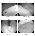
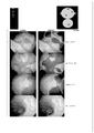
- (A) to (D) are diagrams showing an endoscopic image showing an anatomical structure in the bladder which is a key frame.
- (A) and (B) are diagrams showing examples of key points calculated from a front frame and a rear frame, respectively.
- FIGS. (A) to (C) are diagrams used to explain an example of provisional marking of position data of a plurality of rear frames.
- (A) to (C) are used to explain that the relative spacing of the plurality of rear frames during this period when the next key frame position data is determined is determined.
- It is a figure which shows an example of observation campus data. It is a figure which shows the marking state of the observation campus corresponding to the observation campus data. It is a figure which shows the basic structure of a diagnostic imaging support system. It is a figure which shows the structure of the image diagnosis support system by annotation extension. It is a figure which shows the flow chart of learning of the annotation information extension model.
- (A) and (B) are diagrams showing annotation information corresponding to a bladder endoscopic image and extended annotation information.
- FIG. 1 It is a figure comparing the diagnostic accuracy before and after applying the annotation extension. It is a figure which shows the flowchart in the case of making the lesion classification image diagnosis model by the image diagnosis model which limited the lesion area.
- (A) and (B) are diagrams showing the results of lesion classification before and after using the lesion classification diagnostic imaging model in the lesion region limited diagnostic imaging model. It is a figure which shows an example of the display screen which displayed the observation result and the diagnosis result. It is a figure which shows the other example of the display screen which displayed the observation result and the diagnosis result. It is a figure which shows an example of an output report.
- the endoscopic diagnosis support method and system of the present invention include an endoscopic image taken by an image pickup device by inserting an image pickup device provided at the tip of the endoscope inside a cavity in a subject's organ. Based on multiple frames, we will support the diagnosis of the presence or absence of organ lesions using a computer.
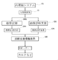
- FIG. 1 is a flowchart showing an outline of a plurality of steps to be performed when the endoscopic diagnosis support method of the present invention is realized by using a computer. As shown in FIG. 1, the endoscopic image EI obtained from the existing endoscopic system ES is processed by the observation recording step ORS and the diagnostic imaging support step IDS.
- an observation record is obtained from the endoscopic image EI and stored as observation record information ORI in a storage means of a computer.
- image diagnosis support step IDS support information for diagnosing the presence or absence of an organ lesion from the endoscopic image EI is stored in a computer storage means as an image diagnosis result IDR.
- the diagnosis support information display step unit SID realized by a computer outputs a diagnosis report including at least one of the observation record information ORI and the image diagnosis result IDR on the screen of the display device, a medical record, or the like.
- the form of output is arbitrary. For example, a moving image displaying the image diagnosis result IDR on the screen may be output.
- FIG. 2 shows a specific processing flow in the observation recording step ORS in the embodiment of the endoscopic diagnosis support method of the present invention.
- the preparatory step (first step) S1 of the observation campus is performed in advance, and then the frame marking step (second step) S2, Observation recording is performed by performing the key point calculation step (third step) S3, the front-rear frame displacement amount calculation step (fourth step) S4, and the front-rear frame marking step (fifth step) S5.
- a computer program for performing these steps is installed in the computer to realize a plurality of means for performing each step inside the computer. ..
- a computer program for an endoscopic diagnosis support system is also configured to include algorithms that perform these steps.
- step S1 the observation campus data about the observation campus for the endoscopic image of the cavity of the organ is prepared as electronic data in the memory of the computer.
- the observation campus data is an electronic data of the observation campus.
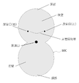
- a simulated deployment observation campus SOC in which the positions of a plurality of openings and the apex of the cavity of the organ are generally specified and one opening is arranged in the central portion can be used.
- FIG. 3 shows an example of a simulated deployment observation campus when the bladder is used as the organ to be observed.
- the bladder is assumed to be a sphere, and two hemispheres, the anterior wall side (ventral) and the posterior wall side (back) of the bladder, are prepared as circles. ..
- the left and right ureteral openings as openings (for example, 3/8 from the bottom of the upper circle and 1/4 left and right), the interureteral ligaments between them, and the urethral openings as openings (2).
- the center of the joint between the two circles) and the top are drawn.
- FIG. 4 is a conceptual diagram when the simulated deployment observation campus SOC of FIG. 3 is used as observation campus data.
- a symbol indicating the existence and type of position data is displayed in the matrix MX formed by arranging a plurality of segments (square segments in this example) of the same size and shape assumed on the simulated deployment observation campus.
- the attached data will be used as observation campus data.
- ellipses instead of hemispheres to make a simulated deployment observation campus. As shown in FIG.
- a flag (0) indicating that there is no unobserved or position data is set as an initial value in the region of all the segments sg of the matrix MX of the observed campus data.
- the position information (coordinates) of the two-dimensional array with the urinary meatus as the origin in the simulated development observation campus SOC is individually attached to each segment sg.
- a flag (1) indicating that the left ureteral opening is observed but uncertain is attached to the corresponding segment.
- a key frame containing one or more anatomical structures capable of locating the organ in the cavity in the frame is determined and keyed to the observed campus data.
- Mark the keyframe position data of the frame is one or more anatomical structures that serve as a reference point when determining a relative position in a cavity (in the case of a bladder, two ureteral meatus, a urethral meatus, and a top where air bubbles collect).
- the position data is the absolute position information with respect to the origin or the position information relative to the reference point and the frame number in the observation campus data.
- Key frame position data is data relating to the position of one or more anatomical structures that serve as reference points on the observation campus. Specifically, if the observation campus is a simulated deployment observation campus, the data are related to the positions of one or more anatomical structures determined by the position coordinates on the simulated deployment observation campus.
- the marking of the key frame position data of the key frame means that the position information (coordinates of the segment sg) and the frame number of the image are stored in association with the observation campus data.
- the frame in which either the left or right ureteral ostium is reflected in the image of the frame taken by the bladder endoscope shown in FIG. 6 is determined as the start key frame, and the corresponding area on the observation campus is the start key frame.
- the marking is a flag (1) indicating that the flag of the corresponding area (segment) on the observation campus is an observed candidate, and the position information is associated with the frame image. That is.
- the initial value [flag (1)] of the marking area is set in a circle having a size of 1/10 of the circle of the observation campus, with the size that is always in the field of view when observing the bladder endoscope as a guide. Given to the incoming segment.
- the start key frame is set as the first front frame, and three or more key points existing on the front frame and the rear frame in the plurality of frames are determined and the key points are determined.
- the key point is a pixel indicating the same place on the inner wall of the organ reflected in the continuous front and rear frames.
- the calculation of the coordinates in the endoscopic image of the key point is a known self-position as disclosed in Visual SLAM (Simultaneous Localization and Mapping: map construction / self-position estimation) applied in automatic driving and robot vision. It is possible to use the image feature points used in the estimation technique. Many characteristic parts reflected in the frame are recognized as feature points, and the coordinates of the key points in the endoscopic image are calculated with the feature points as common parts.
- the displacement amount calculation step (fourth step) S4 three or more key points in the front frame and three or more key points in the rear frame are based on the coordinates in the endoscopic image of the three or more key points. Calculate the amount of displacement between the key points.
- the displacement amount includes the direction and angle in which the three or more key points in the front frame move, and the distance between the three or more key points in the front frame and the rear frame.
- the relative position information of the rear frame calculated from the position information of the front frame marked on the observation campus is calculated, the position information and the frame image are linked, and the rear frame is continuous with the front frame. Mark as the next rear frame.
- the observed candidate flag (1) is marked on the observation campus while repeating the above process until the next key frame is detected.
- FIG. 7 (A) and 7 (B) show endoscopic images of the anterior and posterior frames imaged on the inner wall of the bladder.
- the three points A, B, and C in the front frame correspond to the three points A', B', C'in the rear frame.
- the coordinates of the three points A, B, and C are A (x A , y A ), B (x B , y B ), and C (x C , y C ), and the three points A', B', C'
- the moving distance and direction of the front and rear frames Is the difference between the center of gravity G of the three points A, B, C in the front frame and the center of gravity G'of the three points A', B', C'in the rear frame obtained by the following equation (1) of the center of gravity G. It can be obtained as a vector of G'-G).
- the displacement of the size from the front frame to the rear frame can be calculated by the average difference of the distances from the three points to the center of gravity as shown in the following equation (2).
- the rotation can be calculated from the average of the angles formed by the vectors from the three points to the center of gravity, as shown in the following equation (3).
- the front-back frame marking step (fifth step) S5 at least the displacement amount and the first keyframe position data marked first in the second step and the next keyframe position data marked later in the second step.
- the observed campus data is marked with fixed position data for multiple posterior frames.
- the provisional position data of the plurality of rear frames is marked as the provisional position data of the plurality of rear frames until the next key frame position data is determined.
- the flag of each segment indicating the relative position of each frame remains the observed candidate (1).
- FIG. 8B and 8C the flag of each segment indicating the relative position of each frame remains the observed candidate (1).
- the relative information from the start key frame that has been marked up to that point is the relative position of the frame with the observation candidate flag (1) on the observation campus so that the marking area size and travel distance are halved.
- the coefficient and area size of the travel distance calculation formula are halved, and space is provided on the observation campus so that the marking step can be continued thereafter.
- the coefficient of "1/2" is for convenience, and is not limited to this value, as it is determined so that a plurality of rear frames as observed candidates do not appear on the matrix.
- the first key frame position data position data of the left urinary tract opening
- the next key are determined. Adjust the relative positions of the multiple provisional rear frames so that the position data of the multiple provisional rear frames (as observed candidates) fit between the frame position data and confirm the marking of the rear frame position data. do.
- the relative positions of the plurality of rear frames between the two key frame positions are determined, and the absolute position is determined. Will be done. As shown in FIGS.
- the position data of each frame whose observation is confirmed includes the absolute position information (coordinates) and the frame number of the plurality of segments sg of the observed position.
- the absolute position information is a row of an array with the urinary meatus as the origin in the matrix MX formed by arranging a plurality of segments sg of the same size and shape assumed on the simulated deployment observation campus. It is represented by the coordinates determined by the column.
- the flags in the plurality of segments of the observation campus data are displayed. , It becomes either a flag (0) indicating that there is no marking or a flag (2) indicating that there is marking.
- FIG. 10B the area of the plurality of segments of the flag (0) is set to black, the area of the plurality of segments of the flag (2) is set to gray, and the area of the observation campus is displayed in different colors. Then, it is possible to clearly indicate the presence / absence and location of the area (gray color area) that is not observed by the endoscope.
- the anterior-posterior frame marking step (fifth step) S5 for a frame diagnosed as having a possibility of being a frame containing a lesion, in the anterior-posterior frame marking step (fifth step) S5.
- the absolute position information and frame number of the segment corresponding to each frame can be used to identify the imaging position of the frame containing the lesion. This makes it possible to inform the proper location of the lesion when performing a subsequent work-up or surgery.
- the diagnostic imaging support step IDS (sixth step) of FIG. 1 is performed for a plurality of frames in parallel with the execution of the second step to the fifth step, and is marked with respect to the observation campus data. Based on the position data of the organ and the endoscopic images in multiple frames, we support the image diagnosis of the presence or absence of lesions in organs. However, after performing the second step to the fifth step, the presence or absence of organ lesions is imaged based on the plurality of position data marked with respect to the observation campus data and the endoscopic images in the plurality of frames. You may try to assist in the diagnosis.
- image diagnosis support is performed using the trained image diagnosis model as follows.
- the trained diagnostic imaging model is realized in a computer and constitutes so-called artificial intelligence together with a database.
- the image diagnosis support step IDS (sixth step) has been trained and generated by the image diagnosis model DM using the data recorded in the endoscopic image database DB as learning data. It can be realized by an image diagnosis support system having artificial intelligence using an image diagnosis model TDM.
- the doctor shows normal normal endoscopic image data and lesion endoscopic image data including lesions, and whether or not there is a lesion in these images. Annotation information data indicating information is recorded.
- a sixth step (support system) is realized in order to observe the endoscopic image EI by using the trained diagnostic imaging model TDM obtained by learning the diagnostic imaging model DM using these data. ..
- a deep learning model used for image classification and object detection such as GoogleNet, Inception model, U-Net, ResNet, YOLO, SSD can also be used.
- Artificial intelligence improves its diagnostic accuracy depending on the quality and quantity of learning data.
- the image quality is good, but accurate annotation information by a doctor is set. Therefore, in this example, normal and lesion endoscopic images and annotation information are recorded in the endoscopic image database.
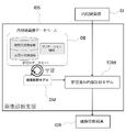
- FIG. 12 shows a configuration of an image diagnosis support system that implements an image diagnosis support step IDS (sixth step) using an annotation extended model AEM in order to solve this problem.
- the annotation extended model AEM is provided in the endoscope image database DB to create extended annotation information.
- FIG. 13 shows a specific flow for learning the annotation extension model AEM.
- the annotation extension model AEM shown in FIG. 13 is an autoencoder-based annotation extension model composed of an encoder E and a decoder D. The autoencoder learns parameters so that even if the dimension of the input information is restored by the decoder D using the latent variable once compressed by the encoder E, the input information and the output information return to the same information.
- This annotation extension model uses the diagnostic imaging model DM as a feature extractor FE and inputs each pixel from the intermediate layer of the diagnostic imaging model DM by inputting the lesion endoscopic image LEI recorded in the endoscopic image database.
- the feature amount (H, W, M) corresponding to the above is obtained, input to the encoder E together with the annotation information (H, W, C) corresponding to the lesion endoscopic image LEI, and output from the encoder E.
- Extended annotation information (H, W, C') as new encoder information by inversely calculating the variables (1, 1, L) and the feature quantities (H, W, M) obtained from the feature extractor FE with the decoder D. Is configured to generate.
- the latent variable is a variable that influences the interpretation of the relationship between the variables, and is, for example, a variable that influences the habit of annotating the endoscope image in the endoscope image database.
- the feature amount H is "Feature Map Height”, which is a feature amount in the height direction of the pixel array in the feature map of the convolutional neural network.
- W is "Feature Map Width”, which is a feature amount in the width direction of the pixel array in the feature map of the convolutional neural network.
- M is “Feature Map Depth”, which is a feature amount in the depth direction of the pixel in the feature map of the convolutional neural network.
- C is "Number of Classes", which is the number of classes assigned to each pixel in the annotation information.
- L is "Latent Vector Length", which is the latent vector length of the latent variable.
- annotation extension model AEM useful extended annotation information can be provided to the doctor from the endoscopic image in the original endoscopic image database even if the training data is small, without newly increasing the annotation information. You can get a new one without forcing it.
- GAN Geneative Adversarial Network
- VAE Virtual Autoencoder
- 14 (A) and 14 (B) show examples of a plurality of extended annotation information generated by the trained annotation extended model from the target endoscopic images, respectively. As can be seen in these figures, it is possible to generate multiple extended annotation information from the same endoscopic image that is close to the original annotation information given by the doctor.
- the annotation extension model AEM randomly expands the extension annotation information.
- the extended annotation information is generated according to the probability distribution defined by the latent variable in the learned annotation extended model. Random expansion means that the latent variables are randomly selected to generate the extended annotation information, instead of generating all the extended annotation information according to the probability distribution. Specifically, as described in the examples of FIGS. 14A and 14B, it means that, for example, one extended annotation information is randomly generated from the five extended annotation information that can be generated. By doing so, it is possible to obtain the extended annotation information without biasing without increasing the extended annotation information more than necessary.
- the existing data expansion method if M times the existing data expansion and L times the annotation expansion are performed for N data sets, the extended data set will be L ⁇ M ⁇ N data sets. Is extended to.
- FIG. 15 shows a case where the expansion model is trained using the training data obtained by adding the expansion data expanded by using the existing data expansion to the existing training data, and the case where the expansion data obtained by the existing data expansion and the annotation expansion are obtained.
- the diagnostic accuracy F when the extended model is trained by adding the data to the existing training data as the training data is shown.
- the horizontal axis is the ratio of training data
- baseline 1.0 is the case where 100% of the training data in the endoscopic image database is used for training
- student 1.0 is the case where the extended data obtained by existing data expansion is used for training.
- This is a case where the extended data obtained by the existing data expansion and the extended data obtained by the annotation expansion are used for training for 100% of the training data in the spectroscopic image database. From FIG.
- the diagnostic accuracy F when the annotation extension used for learning is used is improved.
- the accuracy is better than when only data expansion with 100% of the training data amount is used, and learning accuracy with data with few annotation expansion methods. It can be seen that it is improving.
- the annotation extension model AEM trained by the training data set is used.
- the learning accuracy of the diagnostic imaging model DM can be further improved.
- the diagnostic imaging support system that implements the sixth step, it is possible to have lesions in the endoscopic image using a trained diagnostic imaging model that has been trained using the data recorded in the endoscopic image database as training data.
- the diagnosis may be assisted by detecting a region with high sex and diagnosing whether the region with high possibility of lesion is a lesion.
- the endoscopic image contains both the part that seems to be normal and the part that seems to be a lesion. Therefore, if a diagnosis of normality or lesion is made as a target for evaluating a region having a high possibility of lesion, the diagnostic accuracy can be improved rather than evaluating the whole.
- FIG. 16 shows a specific example for creating a learned image diagnosis model (learned lesion area detection image diagnosis model and learned lesion classification image diagnosis model) for performing image diagnosis support by area-limited lesion classification in the sixth step.
- the lesion area detection diagnostic imaging model LADM used in FIG. 16 is an diagnostic imaging model for extracting image feature quantities (H, W, M) in all pixels from the lesion endoscopic image LEI and the normal endoscopic image NEI. be.
- the region with high lesion is identified from the endoscopic images LEI and NEI, and the feature of the region with high possibility of lesion is used by using the image features of multiple pixels in the region with high possibility of lesion.
- the amount (region-limited feature amount: H, W, M ⁇ 0/1) is calculated.
- the lesion candidate feature amount (1,1, avg (M ⁇ 1)) is obtained from this region-limited feature amount: H, W, M ⁇ 0/1).
- This lesion candidate feature amount (1,1, avg (M ⁇ 1)) is an average value in the region where the feature amount M of each pixel (pixel) is 1 part of the lesion candidate mask (H, W, 0/1). Is.
- the region with a high possibility of lesion is classified into normal and lesion based on the lesion candidate feature amount (1,1, avg (M ⁇ 1)).
- a diagnostic imaging model for creating a trained diagnostic imaging model for diagnostic support is constructed.
- the lesion area detection diagnostic imaging model LADM creates a lesion probability map (H, W, L) from the image features (H, W, M) of all the pixels in one image and the endoscopic image.
- Resnet 50 which is a convolutional neural network having a depth of 50 layers
- the binarization processing unit BP binarizes the lesion probability map (H, W, L) to create a lesion candidate mask (H, W, 0/1). Further, as the binarization processing unit BP, "Otsu's binarization method", which is an image binarization method, can be used.
- the area-limited feature amount calculation unit ALFC multiplies the image feature amount (H, W, M) and the lesion candidate mask (H, W, 0/1) to limit the area-limited feature amount to the area with a high possibility of lesion. Find (H, W, M ⁇ 0/1).
- the lesion candidate feature amount calculation unit LFC averages the portion of the limited region (M ⁇ 1) of the region-limited feature quantity (H, W, M ⁇ 0/1) to form a lesion candidate in a region with a high possibility of lesion.
- the feature amount (1,1, avg (M ⁇ 1)) is calculated.
- the lesion classification diagnostic imaging model LCDM classifies the region having a high possibility of lesion into normal and lesion based on the lesion candidate feature amount (1,1, avg (M ⁇ 1)).
- a multi-layer perceptron method (MLP method) including a softmax function (Softmax), which is an activation function, can be used for the lesion classification diagnostic imaging model LCDM.
- Softmax softmax function
- the image feature amounts (H, W, M) of each pixel are obtained from the intermediate layer of the lesion region detection image diagnosis model LADM.
- the learned lesion area detection image diagnosis model and the learned lesion obtained by learning the lesion area detection image diagnosis model LADM and the lesion classification image diagnosis model LCDM shown in FIG. 16 A trained diagnostic imaging model using a classified diagnostic imaging model is used. By using such a trained diagnostic imaging model, it is possible to improve the determination accuracy of a region having a high possibility of a lesion.
- FIGS. 17A and 17B show the lesion determination result when the region is not limited and the lesion determination result when the region is limited.
- the vertical axis is the evaluation index [IoU]
- the horizontal axis is the size of the lesion area.
- IoU ⁇ 0.4 is correctly determined as a lesion
- IoU ⁇ 0.4 is an oversight of the lesion. Comparing FIGS. 17A and 17B, the number of oversights of microlesions (area: 0-100) was 11 when the area was not limited, but the number of oversights was 6 when the area was limited. .. From this result, it can be seen that the determination accuracy can be improved by detecting the region having a high possibility of lesion in the endoscopic image and diagnosing whether the region having a high possibility of lesion is a lesion.
- FIG. 18 shows an example of a display screen of a display device of an image diagnosis support system that implements an image diagnosis support method.
- the patient's chart information D1 the observation position display D2 that displays the positions of multiple observed areas and the detected lesions on a diagram that imitates the observation campus, and the lesions in the observed area where the lesions are present.
- An endoscope in which the diagnosis result display D3 that displays the malignancy and type of the lesion, the original endoscopic image D4 with the lesion, and the result of image diagnosis support when the lesion is determined are superimposed on the endoscope image.
- the image diagnosis support image D5 is displayed on the display screen. By doing so, the observation result and the diagnosis result can be confirmed on the display screen.
- FIG. 19 shows another example of the display screen of the display device.
- the patient's chart information D1 the observation position display D2 that displays the positions of a plurality of observed areas and the detected lesions on a diagram that imitates the observation campus, and the observed areas where the lesions are present.
- Diagnosis result display D3 that displays the malignancy and type of the lesion, the original endoscopic image D4 with the lesion, and the endoscopic image that superimposes the result of image diagnosis support when the lesion is judged to be on the endoscopic image.
- the mirror image diagnosis support image D5 is displayed on the display screen.
- the processing status display D6 and the lesion candidate thumbnail image D7 that further display the processing status are displayed.
- the treatment status display D6 sequentially displays the observation time and the presence or absence of lesions after the treatment. Therefore, when the vertical line in the processing status display D6 is clicked, the endoscopic image diagnosis support image at that time is displayed as the lesion candidate thumbnail image D7.
- the image displayed on the endoscopic image diagnosis support image D5 obtained as a diagnosis result at the observation time is displayed as a thumbnail as a lesion candidate.
- the display of D1, D2, and D3 changes according to the selected thumbnail.
- FIG. 20 shows an example of an output report. An image corresponding to the check status of the check box of the lesion candidate thumbnail image D7 in FIG. 19 is displayed.
- the example of the output report is not limited to the example of FIG.
- An image pickup device provided at the tip of an endoscope is inserted into a cavity inside a subject's organ, and the organ is based on a plurality of frames including an endoscope image captured by the image pickup device. It is an endoscopic diagnosis support system that diagnoses the presence or absence of lesions using a computer.
- the computer The first step of preparing observation campus data for the observation campus of the endoscopic image of the cavity, A second that determines a keyframe in which the frame contains one or more tissues capable of locating the organ within the cavity and marks the keyframe position data of the keyframe against the observation campus data.
- With respect to the observed campus data at least based on the displacement and the first keyframe position data first marked in the second step and the next keyframe position data later marked in the second step.
- the fifth step of marking the fixed position data of the plurality of rear frames Marking on the observation campus data for the plurality of frames in parallel with performing the second step to the fifth step or after performing the second step to the fifth step.
- the endoscopy is configured to perform a sixth step to assist in diagnostic imaging of the presence or absence of a lesion in the organ based on the plurality of confirmed position data and the plurality of frames.
- Mirror diagnosis support system is configured to perform a sixth step
- An observation position display that displays a plurality of observed areas on a diagram that imitates the observation campus, and an observation position display.
- a lesion position display that displays the observed area where the lesion is present on a diagram that imitates the observation campus, and a lesion position display.
- a diagnostic result display showing the malignancy and type of the lesion in the observed area where the lesion is present, and The endoscopic diagnosis support system according to the above [1], wherein at least one of the display of the medical record information of the subject is displayed on the display screen of the display device.
- An image pickup device provided at the tip of the endoscope is inserted into the cavity inside the organ of the subject, and the organ is based on a plurality of frames including an endoscope image captured by the image pickup device.
- It is an endoscopic diagnosis support system that supports the diagnosis of the presence or absence of lesions using a computer.
- the trained diagnostic imaging model trained using the data recorded in the endoscopic image database as training data the data recorded in the endoscopic image database was used as training data.
- An endoscopic diagnosis support system characterized by detecting a region having a high possibility of a lesion in an endoscopic image and supporting the region by diagnosing whether or not the region having a high possibility of a lesion is a lesion.
- An image pickup device provided at the tip of an endoscope is inserted into the cavity inside the subject's organ, and the organ is based on a plurality of frames including an endoscope image captured by the image pickup device.
- the installed computer The first step of preparing observation campus data for the observation campus of the endoscopic image of the cavity, Determine a keyframe in which the frame contains one or more anatomical structures capable of locating the organ within the cavity and mark the keyframe position data of the keyframe against the observation campus data.
- a sixth step is performed to support diagnostic imaging of the presence or absence of lesions in the organ based on the plurality of confirmed position data and the endoscopic images in the plurality of frames.
- the first support system that provides diagnostic support using a trained diagnostic imaging model that has been trained using the data recorded in the endoscopic image database including image data with annotation information as training data.
- a region in the endoscopic image that is likely to be a lesion is detected, and the lesion is detected.
- a computer for endoscopic diagnosis support characterized in that it is configured to realize at least one of a second support systems that provide diagnostic support by diagnosing whether an area with a high probability is a lesion. program.
- the observation campus data of the inner wall in the target organ is marked, it is possible to clearly determine the area inspected and the area not inspected, and the inside of the target organ is observed all over. Moreover, it is possible to correctly record where the captured image was taken.
- the plurality of position data marked on the observation campus data and the endoscopic images in the plurality of frames it is possible to support the image diagnosis of the presence or absence of lesions in the organs.
Landscapes
- Engineering & Computer Science (AREA)
- Health & Medical Sciences (AREA)
- Medical Informatics (AREA)
- Physics & Mathematics (AREA)
- Theoretical Computer Science (AREA)
- General Health & Medical Sciences (AREA)
- Public Health (AREA)
- General Physics & Mathematics (AREA)
- Computer Vision & Pattern Recognition (AREA)
- Biomedical Technology (AREA)
- Life Sciences & Earth Sciences (AREA)
- Nuclear Medicine, Radiotherapy & Molecular Imaging (AREA)
- Radiology & Medical Imaging (AREA)
- Pathology (AREA)
- Primary Health Care (AREA)
- Epidemiology (AREA)
- Multimedia (AREA)
- Databases & Information Systems (AREA)
- Surgery (AREA)
- Evolutionary Computation (AREA)
- Data Mining & Analysis (AREA)
- Artificial Intelligence (AREA)
- Optics & Photonics (AREA)
- Molecular Biology (AREA)
- Veterinary Medicine (AREA)
- Animal Behavior & Ethology (AREA)
- Heart & Thoracic Surgery (AREA)
- Biophysics (AREA)
- Computing Systems (AREA)
- Quality & Reliability (AREA)
- Software Systems (AREA)
- Signal Processing (AREA)
- Endoscopes (AREA)
Priority Applications (3)
| Application Number | Priority Date | Filing Date | Title |
|---|---|---|---|
| JP2022568297A JP7388648B2 (ja) | 2020-12-08 | 2021-12-07 | 内視鏡診断支援方法及び内視鏡診断支援システム |
| US18/256,083 US12488896B2 (en) | 2020-12-08 | 2021-12-07 | Method and system for endoscopic diagnosis support |
| CN202180093283.7A CN116916807A (zh) | 2020-12-08 | 2021-12-07 | 用于内窥镜诊断支持的方法和用于内窥镜诊断支持的系统 |
Applications Claiming Priority (2)
| Application Number | Priority Date | Filing Date | Title |
|---|---|---|---|
| JP2020203765 | 2020-12-08 | ||
| JP2020-203765 | 2020-12-08 |
Publications (1)
| Publication Number | Publication Date |
|---|---|
| WO2022124315A1 true WO2022124315A1 (ja) | 2022-06-16 |
Family
ID=81974510
Family Applications (1)
| Application Number | Title | Priority Date | Filing Date |
|---|---|---|---|
| PCT/JP2021/045003 Ceased WO2022124315A1 (ja) | 2020-12-08 | 2021-12-07 | 内視鏡診断支援方法及び内視鏡診断支援システム |
Country Status (4)
| Country | Link |
|---|---|
| US (1) | US12488896B2 (https=) |
| JP (1) | JP7388648B2 (https=) |
| CN (1) | CN116916807A (https=) |
| WO (1) | WO2022124315A1 (https=) |
Families Citing this family (4)
| Publication number | Priority date | Publication date | Assignee | Title |
|---|---|---|---|---|
| CN117173075B (zh) * | 2022-05-24 | 2026-01-23 | 鸿海精密工业股份有限公司 | 医学图像检测方法及相关设备 |
| US20240005532A1 (en) * | 2022-07-04 | 2024-01-04 | Hefei University Of Technology | Dynamic tracking methods for in-vivo three-dimensional key point and in-vivo three-dimensional curve |
| EP4461252A1 (en) * | 2023-05-10 | 2024-11-13 | Stryker Corporation | Systems and methods for tracking locations of interest in endoscopic imaging |
| CN118918170B (zh) * | 2024-10-10 | 2025-02-14 | 荣耀终端有限公司 | 位移检测方法、屏幕检测方法和检测装置 |
Citations (3)
| Publication number | Priority date | Publication date | Assignee | Title |
|---|---|---|---|---|
| JP2017205343A (ja) * | 2016-05-19 | 2017-11-24 | オリンパス株式会社 | 内視鏡装置、内視鏡装置の作動方法 |
| JP2018050890A (ja) * | 2016-09-28 | 2018-04-05 | 富士フイルム株式会社 | 画像表示装置及び画像表示方法並びにプログラム |
| CN109146884A (zh) * | 2018-11-16 | 2019-01-04 | 青岛美迪康数字工程有限公司 | 内窥镜检查监控方法及装置 |
Family Cites Families (6)
| Publication number | Priority date | Publication date | Assignee | Title |
|---|---|---|---|---|
| CA2314794A1 (en) * | 2000-08-01 | 2002-02-01 | Dimitre Hristov | Apparatus for lesion or organ localization |
| WO2014168128A1 (ja) | 2013-04-12 | 2014-10-16 | オリンパスメディカルシステムズ株式会社 | 内視鏡システム及び内視鏡システムの作動方法 |
| WO2016044624A1 (en) | 2014-09-17 | 2016-03-24 | Taris Biomedical Llc | Methods and systems for diagnostic mapping of bladder |
| WO2019088121A1 (ja) | 2017-10-30 | 2019-05-09 | 公益財団法人がん研究会 | 画像診断支援装置、資料収集方法、画像診断支援方法および画像診断支援プログラム |
| JP2019180966A (ja) | 2018-04-13 | 2019-10-24 | 学校法人昭和大学 | 内視鏡観察支援装置、内視鏡観察支援方法、及びプログラム |
| WO2021014584A1 (ja) | 2019-07-23 | 2021-01-28 | Hoya株式会社 | プログラム、情報処理方法及び情報処理装置 |
-
2021
- 2021-12-07 CN CN202180093283.7A patent/CN116916807A/zh active Pending
- 2021-12-07 US US18/256,083 patent/US12488896B2/en active Active
- 2021-12-07 WO PCT/JP2021/045003 patent/WO2022124315A1/ja not_active Ceased
- 2021-12-07 JP JP2022568297A patent/JP7388648B2/ja active Active
Patent Citations (3)
| Publication number | Priority date | Publication date | Assignee | Title |
|---|---|---|---|---|
| JP2017205343A (ja) * | 2016-05-19 | 2017-11-24 | オリンパス株式会社 | 内視鏡装置、内視鏡装置の作動方法 |
| JP2018050890A (ja) * | 2016-09-28 | 2018-04-05 | 富士フイルム株式会社 | 画像表示装置及び画像表示方法並びにプログラム |
| CN109146884A (zh) * | 2018-11-16 | 2019-01-04 | 青岛美迪康数字工程有限公司 | 内窥镜检查监控方法及装置 |
Also Published As
| Publication number | Publication date |
|---|---|
| US12488896B2 (en) | 2025-12-02 |
| JPWO2022124315A1 (https=) | 2022-06-16 |
| US20240038391A1 (en) | 2024-02-01 |
| JP7388648B2 (ja) | 2023-11-29 |
| CN116916807A (zh) | 2023-10-20 |
Similar Documents
| Publication | Publication Date | Title |
|---|---|---|
| JP7388648B2 (ja) | 内視鏡診断支援方法及び内視鏡診断支援システム | |
| CN111214255B (zh) | 一种医学超声图像计算机辅助方法 | |
| JP6080248B2 (ja) | 3次元画像表示装置および方法並びにプログラム | |
| CN111227864B (zh) | 使用超声图像利用计算机视觉进行病灶检测的装置 | |
| CN107909585B (zh) | 一种血管内超声影像的血管中内膜分割方法 | |
| JP5584006B2 (ja) | 投影画像生成装置、投影画像生成プログラムおよび投影画像生成方法 | |
| CN111161290A (zh) | 一种图像分割模型的构建方法、图像分割方法及系统 | |
| US20110187707A1 (en) | System and method for virtually augmented endoscopy | |
| WO2022194126A1 (zh) | 基于胶囊内窥镜构建阅片模型的方法、设备及介质 | |
| CN111311626A (zh) | 基于ct图像的颅骨骨折自动检测方法及电子介质 | |
| CN107993228B (zh) | 一种基于心血管oct影像的易损斑块自动检测方法和装置 | |
| CN116958147B (zh) | 基于深度图像特征的目标区域确定方法、装置和设备 | |
| CN116324897A (zh) | 用于重建管状器官的三维表面的方法和系统 | |
| CN116051553B (zh) | 一种在三维医学模型内部进行标记的方法和装置 | |
| JP2017522072A (ja) | 信頼度マッチング付き生体内マルチカメラカプセルからの画像の再構築 | |
| JPWO2022124315A5 (https=) | ||
| JP7768398B2 (ja) | 内視鏡検査支援装置、内視鏡検査支援方法、及び、プログラム | |
| CN112734707A (zh) | 一种3d内窥镜辅助检测方法、系统、装置及存储介质 | |
| CN116712167A (zh) | 一种肺结节手术导航方法和系统 | |
| JP2003263498A (ja) | 検査されるべき対象の様々な画像を形成する方法 | |
| TWI886431B (zh) | 輔助評估系統及其方法 | |
| JP2007105352A (ja) | 差分画像表示装置、差分画像表示方法およびそのプログラム | |
| CN117522712A (zh) | 一种三维实景医学影像与路径图融合方法及系统 | |
| JP2024008815A (ja) | 画像処理装置、画像処理方法および記録媒体 | |
| CN106504226B (zh) | 超声图像膀胱脱垂自动分级系统 |
Legal Events
| Date | Code | Title | Description |
|---|---|---|---|
| 121 | Ep: the epo has been informed by wipo that ep was designated in this application |
Ref document number: 21903414 Country of ref document: EP Kind code of ref document: A1 |
|
| ENP | Entry into the national phase |
Ref document number: 2022568297 Country of ref document: JP Kind code of ref document: A |
|
| NENP | Non-entry into the national phase |
Ref country code: DE |
|
| WWE | Wipo information: entry into national phase |
Ref document number: 202180093283.7 Country of ref document: CN |
|
| WWE | Wipo information: entry into national phase |
Ref document number: 18256083 Country of ref document: US |
|
| 122 | Ep: pct application non-entry in european phase |
Ref document number: 21903414 Country of ref document: EP Kind code of ref document: A1 |