WO2022124186A1 - レンズ構造 - Google Patents
レンズ構造 Download PDFInfo
- Publication number
- WO2022124186A1 WO2022124186A1 PCT/JP2021/044224 JP2021044224W WO2022124186A1 WO 2022124186 A1 WO2022124186 A1 WO 2022124186A1 JP 2021044224 W JP2021044224 W JP 2021044224W WO 2022124186 A1 WO2022124186 A1 WO 2022124186A1
- Authority
- WO
- WIPO (PCT)
- Prior art keywords
- lens
- welding
- flange portion
- lens holder
- holder
- Prior art date
- Legal status (The legal status is an assumption and is not a legal conclusion. Google has not performed a legal analysis and makes no representation as to the accuracy of the status listed.)
- Ceased
Links
Images







Classifications
-
- F—MECHANICAL ENGINEERING; LIGHTING; HEATING; WEAPONS; BLASTING
- F21—LIGHTING
- F21S—NON-PORTABLE LIGHTING DEVICES; SYSTEMS THEREOF; VEHICLE LIGHTING DEVICES SPECIALLY ADAPTED FOR VEHICLE EXTERIORS
- F21S41/00—Illuminating devices specially adapted for vehicle exteriors, e.g. headlamps
- F21S41/20—Illuminating devices specially adapted for vehicle exteriors, e.g. headlamps characterised by refractors, transparent cover plates, light guides or filters
- F21S41/29—Attachment thereof
-
- G—PHYSICS
- G02—OPTICS
- G02B—OPTICAL ELEMENTS, SYSTEMS OR APPARATUS
- G02B3/00—Simple or compound lenses
-
- G—PHYSICS
- G02—OPTICS
- G02B—OPTICAL ELEMENTS, SYSTEMS OR APPARATUS
- G02B7/00—Mountings, adjusting means, or light-tight connections, for optical elements
- G02B7/02—Mountings, adjusting means, or light-tight connections, for optical elements for lenses
Definitions
- the invention of the present application relates to the structure of a lens.
- the vehicle lighting equipment includes a light source and a lens that forms the light emitted from the light source into a predetermined light distribution in the lighting chamber.
- the lens is held by being welded to the lens holder at the flange portion, with the flange portion provided so as not to interfere with the light distribution as the welding portion.
- the lens When the lens is welded to the lens holder, it is welded in one area on the light emitting side of the lens holder and a part of the light incident side of the flange portion. This will be described in detail with reference to FIG.
- FIG. 16 is a schematic configuration diagram for explaining the welding and configuration of a conventional lens and a lens holder.
- the lens 1010 made of a transparent member is provided with a flange portion 1011 on the outer edge portion as a holding portion.
- the lens holder 1020 is made of a translucent member, and an inner flange portion 1022 is provided in the opening to which the lens 1010 is attached.
- the lens holder 1020 When welding the lens 1010 and the lens holder 1020, the lens holder 1020 is first arranged with the inner flange portion 1022 as the upper surface, and the flange portion 1011 of the lens 1010 is positioned and mounted on the inner flange portion 1022 of the lens holder 1020. .. A part of the peripheral flange portion 1011 is pressed toward the inner flange portion 1022 by the welding pressing mechanism P, whereby the inner surface 1016 of the flange portion 1011 and the outer surface 1026 of the inner flange portion 1022 are in close contact with each other. Will be.
- the projected laser beam L When the laser beam L is projected from the laser light source (laser oscillator) M, the projected laser beam L first enters the flange portion 1011, is transmitted in the lens thickness direction, and is projected onto the inner flange portion 1022 on the outer surface. The 1026 is melted and welded to the inner surface 1016 is performed.
- the laser light source laser oscillator
- the welded part can be seen from the front through the transparent lens, which makes it look bad. Therefore, a blindfold material for blindfolding the welded portion is required (see the blindfold material 1090 in FIG. 16B). If a blindfold material is used, the size of the lamp will have to be increased. The number of parts will increase by that amount, leading to increased costs and weight.
- the present invention has been made in view of this, and provides a lens structure that does not require a blindfold material and contributes to miniaturization of a lamp.
- the lens of the present disclosure is a lens formed of a translucent resin member and bonded to a lens holder formed of a translucent resin member by laser welding. Further, an incident surface and an exit surface facing each other and a flange portion as a welding portion to the lens holder are provided, and the flange portion has a larger amount of protrusion of the incident surface toward the light incident side in at least a part of the region. It has a stepped portion having a large amount of protrusion to the light incident side, and the surface of the stepped portion on the light emitting surface side is used as a welding surface with the lens holder so as to be welded and joined to the lens holder. did. According to this aspect, the lens is welded with the welded portion blindfolded by the lens holder, and a blindfold material for blindfolding the welded portion becomes unnecessary.
- the flange portion is configured to be provided over the entire circumference of the outer periphery of the incident surface. According to this aspect, at the time of welding, it is easy to press the lens with a uniform force by the welding pressing mechanism, and it is easy to weld without deviation or bias, which is a suitable form for welding.
- the surfaces of the stepped portion, which is the welding surface, on the exit surface side are all configured to be provided on the same plane. According to this aspect, the lens is easily pressed by the welding pressing mechanism at the time of welding.
- FIG. 5A is a front perspective view of the lens and mainly shows an exit surface.
- FIG. 5B is a rear perspective view of the lens, and mainly shows an incident surface.
- FIG. 5C is a side view of the lens.
- the vertical cross section is also shown by the dotted line. It is a schematic block diagram for demonstrating the welding of the lens.
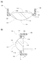
- FIG. 14 (A) is a horizontal cross-sectional view of FIG. 14 (B) is a vertical cross-sectional view of FIG. The same lens is shown.
- FIG. 15A is a front perspective view of the lens, and mainly shows an exit surface.
- FIG. 15B is a rear perspective view of the lens and mainly shows an incident surface.
- FIG. 15C is a plan view of the lens.
- FIG. 15D is a front view of the lens.
- FIG. 15E is a rear view of the lens.
- FIG. 15F is a side view of the lens.
- the vertical cross section is also shown by the dotted line. This is a conventional example.
- the vehicle lamp 1 shown in FIG. 1 is a headlight mounted on the left and right ends of the front end of the vehicle body, and includes the lens 10 according to the first embodiment and the lens holder 20 for holding the lens 10. It is composed.
- the vehicle lamp 1 includes a lamp body 2 and a lamp cover 4.
- the lamp body 2 has an opening in the front, and a lamp cover 4 made of a translucent resin or glass is attached to the opening of the lamp body 2 to form a lamp chamber S.
- a lamp unit LU attached to the support member 6 is arranged in the lamp chamber S.
- the support member 6 is attached to the lamp body 2 by the aiming screw E.
- the optical axis of the vehicle lamp 1 is adjusted in the horizontal direction and the vertical direction by rotating each aiming screw E.
- the lamp unit LU is configured to irradiate a predetermined light distribution to the front of the vehicle, and includes a light source 7, a reflector 8, a lens 10, and a lens holder 20 which are light emitting elements.
- the light source 7 and the lens holder 20 are attached to a metal bracket 9 fixed to the support member 6.
- the reflector 8 is configured to guide the light emitted from the light source 7 to the lens 10, and is attached to the support member 6 via a fixing member (not shown).
- the lens 10 is a free-form surface lens having an incident surface 15 and an emitting surface 19 facing each other, both of which have a free curved surface shape.
- both the entrance surface 15 and the exit surface 19 are convex curved surfaces that bulge outward.
- the light emitting side from which the light of the light source 7 is emitted is arranged in the front
- the incident light incident side is arranged in the rear
- the surface arranged in the front is arranged in the front and rear.
- the surface is referred to as the back surface.
- the emitted light of the light source 7 is reflected forward by the reflector 13, passes through the lens 10 and the lamp cover 4, and is emitted forward to form a predetermined light distribution in front of the vehicle.
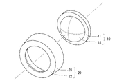
- FIG. 2 is a schematic configuration diagram of the lens 10 and the lens holder 20. The fixing portion of the lens holder 20 to the bracket 9 is omitted.
- FIG. 3 is an exploded perspective view of FIG.
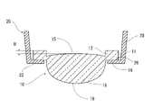
- FIG. 4 is a horizontal cross-sectional view of FIG.
- FIG. 5 shows the lens 10.
- the lens 10 is formed by integrally forming a light transmitting portion 18 formed in a substantially hemispherical shape and a flange portion 11 projecting toward the outer peripheral edge of the light transmitting portion 18 by injection molding.
- the light transmitting portion 18 is a lens body, and the flange portion 11 is a holding portion for being welded and held to the lens holder 20.
- the lens holder 20 is integrally formed with a holding portion 28 formed in a substantially cylindrical shape and an inner flange portion 22 protruding inward from the front end of the holding portion 28.
- the lens holder 20 contains a light-absorbing material such as carbon, is translucent, and is made of a resin that is heated and melted by laser light or the like.
- the lens 10 is made of a transparent resin material that transmits light, for example, acrylic resin (polymethacrylic acid methyl resin) or polycarbonate resin, and when the lamp body 2 is melted, it is melted by the heat thereof.
- acrylic resin polymethacrylic acid methyl resin
- polycarbonate resin a transparent resin material that transmits light
- the flange portion 11 is provided with a stepped portion 12 projecting rearward.
- the stepped portion 12 may be formed in at least a part of the flange portion 11, and is preferably provided at a plurality of locations separated in the circumferential direction.
- the step portion 12 is provided in an annular shape over the entire circumference of the entire region of the flange portion 11.
- the amount of protrusion of the step portion 12 to the rear is configured to be larger than the amount of protrusion of the incident surface 15 to the rear. That is, the separation distance H (see FIG. 4), which is the difference from the protrusion amount of the step portion 12 based on the maximum protrusion amount of the incident surface 15, is configured to be 0 or more.
- the front surface of the step portion 12 is configured as a flat surface without a step, and this flat surface portion becomes a lens welding surface 16 to be welded to the lens holder 20.
- the lens holder 20 has a holder welding surface 26 welded to the lens 10 on the back surface side of the inner flange portion 22, and the lens holder 20 and the lens 10 are joined by welding both welding surfaces.
- FIG. 6 is a conceptual configuration diagram for explaining the shape and welding of the lens 10 and the lens holder 20.
- the lens holder 20 is arranged with the inner flange portion 22 as the bottom surface, the lens 10 is arranged so as to cover the opening of the lens holder 20 with the light transmitting portion 18, and the flange portion 11 is placed on the inner flange portion 22. ..
- the lens 10 and the lens holder 20 are formed with an engaging mechanism such as an uneven portion and an engaging groove (not shown), and the lens welding surface 16 and the holder welding surface 26 are positioned by the engagement mechanism. Arranged so that they face each other and come into contact with each other.
- the flange portion 11 is pressed toward the inner flange portion 22 by a welding pressing mechanism P having a pressing surface urged by an elastic member such as a contact probe, and the lens welding surface 16 and the holder welding surface 26 are pressed. Is in close contact.
- Laser light L is projected from the flange portion 11 side toward the holder welding surface 26 from the laser light source (laser oscillator) M.
- the laser beam L passes through the flange portion 11 and heats the holder welding surface 26 to melt it.
- the lens welding surface 16 in contact with the holder welding surface 26 also generates heat due to heat conduction and melts to fuse the lens welding surface 16 and the holder welding surface 26.
- the lens holder 20 is configured to include a material that absorbs the laser beam L, but the lens 10 does not contain this and transmits light, so that the laser beam in the lens 10 before reaching the lens holder 20.
- the absorption of L is prevented, and a high absorption rate of the laser beam L on the holder welding surface 26 formed as the joint surface can be ensured.
- the lens holder 20 contains a light-diffusing material such as titanium oxide, the laser beam L is diffused to prevent the holder welding surface 26 from being partially excessively melted by the laser beam L. Is possible and preferable.
- the lens welding surface 16 and the holder welding surface 26 are in close contact with each other, and the laser beam L is emitted to melt both welding surfaces, so that both are welded without a gap.
- the lens 10 is exposed from the rear of the lens holder 20 by inserting the light transmitting portion 18 through the opening of the lens holder 20 and exposing it to the front, and is welded to the inner flange portion 22 by the flange portion 11.
- the holder welding surface 26 on the back surface of the lens holder 20 and the lens welding surface 16 on the front side of the lens 10 are welded together, and the welded portions of both are blindfolded by the inner flange portion 22 itself, so that the appearance is good. Is good.
- There is no need for a blindfold member that blindfolds the welded portion resulting in cost savings and weight reduction.
- it since it is not necessary to arrange a blindfold member, it contributes to the miniaturization of the lamp. It saves space and improves the degree of freedom in design and design.
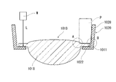
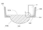
- FIG. 7 is a conventional example for comparison.
- the lens 1010 is arranged in front of the lens holder 1020 and welded to the inner flange portion 1022 by the flange portion 1011.
- a blindfold material 1090 that hides the welded portion is required.
- the welding pressing mechanism P is used to weld the lens 1010. There is a problem that the lens cannot be pressed.
- the diameter W of the welding pressing mechanism P (see FIG. 6) is set to a certain extent in order to secure the strength of the elastic member (for example, the wire thickness and the spring diameter when the elastic member is a spring) required from the required pressing force. Size is required. Further, in order to avoid damage to the light transmitting portion 1018 due to the arrangement of the welding pressing mechanism P, it is necessary to arrange the welding pressing mechanism P with a predetermined margin from the light transmitting portion 1018. Generally, the minimum required diameter W is larger than the minimum welding width required to completely join the lens and the lens holder.
- the lens 1010 when the lens 1010 is arranged in front of the lens holder 1020, a part of the welding pressing mechanism P may be arranged so as to protrude outward from the edge portion of the flange portion 1011.
- the holding portion 1028 serves as a vertical wall, and the welding pressing mechanism P is provided at the edge portion of the flange portion 1011. It cannot be placed so that it protrudes outward from the lens. If the width of the flange portion 1011 is increased in order to avoid interference, the lens holder 1020 must be increased in size, which causes problems such as an increase in size and weight of the entire lamp.
- the flange portion 11 of the lens 10 is provided with a step portion 12 protruding from the incident surface 15, the front surface of the step portion 12 is the lens welding surface 16, and the back surface of the step portion 12 is welded and pressed.
- the welding pressing mechanism P can be arranged so as to protrude inward from the inner end portion of the step portion 12 (see D portion in FIG. 6), and the lens 10 can be arranged without increasing the width of the flange portion 11. Can be welded to the lens holder 20.
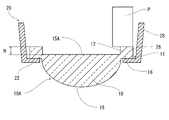
- FIG. 8 shows a modified example of the lens 10.
- the lens 10A shown in FIG. 8 has the same configuration as the lens 10 except that the incident surface 15A is composed of a flat surface. Elements having the same configuration are designated by the same reference numerals and description thereof will be omitted.
- the welding pressing mechanism P is arranged on the stepped portion 12 in the lens 10A as well as the lens 10, and the lens is lensed.
- the welding surface 16 can be brought into close contact with the holder welding surface 26.
- FIG. 9 is a conventional example for explaining the action and effect of the lens 10A shown in FIG.
- the lens 1010A shown in FIG. 9 has the same configuration and arrangement as the conventional lens 1010 shown in FIG. 7, except that the incident surface 1015A is composed of a flat surface.
- the incident surface 1015A is flush with the back surface of the flange portion 1011 and both are configured as the same plane.
- the welding pressing mechanism P protrudes inward from the flange portion 1011 and hangs on the incident surface 1015A (Fig.). See part E of 9). Therefore, there arises a problem that the incident surface 1015A is damaged by the pressing operation of the welding pressing mechanism P, which adversely affects the light distribution.
- FIG. 10 shows another modified example of the lens 10.
- the lens 10B shown in FIG. 10 has the same configuration as the lens 10 except that the incident surface 15B is configured as a concave curved surface protruding forward. Elements having the same configuration are designated by the same reference numerals and description thereof will be omitted.
- the lens 10B includes a flange portion 14 that connects the incident surface 15B, which is a concave curved surface, and the flange portion 11.
- the flange portion 14 continuously and integrally configures the incident surface 15B and the flange portion 11 without forming a local thin portion at the end due to the concave curved surface.
- the flange portion 14 that can be visually recognized from the front is an optical surface and a design surface on which light is incident, and is configured as a part of the incident surface 15B.
- the welding pressing mechanism P is arranged on the stepped portion 12 and the lens welding surface 16 is placed on the holder welding surface, similarly to the lens 10. It can be brought into close contact with 26.
- the welding pressing mechanism P does not come into contact with the flange portion 14, and the welding pressing mechanism P does not press and damage the flange portion 14. The adverse optical and design effects of the welding pressing mechanism P are avoided.
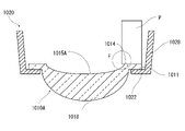
- FIG. 11 is a conventional example for explaining the action and effect of the lens 10B shown in FIG.
- the lens 1010B shown in FIG. 11 has the same configuration as the conventional lens 1010 except that the incident surface 1015B is configured as a concave curved surface.
- the lens 1010B also has a flange portion 1014 that connects the flange portion 1011 and the incident surface 1015.
- the back surface of the flange portion 1014 is flush with the back surface of the flange portion 1011 and both are configured as the same plane.
- the lens 1010B behind the lens holder 1020 and arrange the welding pressing mechanism P on the flange portion 1011.
- the welding pressing mechanism P protrudes inward from the flange portion 1011 and hangs on the flange portion 1014. (See part F in FIG. 11).
- the incident surface and the flange portion 1014 which is the design surface, are damaged, which adversely affects the light distribution.
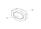
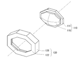
- FIG. 12 is a schematic configuration diagram of the lens 110 and the lens holder 120 according to the second embodiment. The fixing portion to the bracket 9 is omitted.
- FIG. 13 is an exploded perspective view of FIG.
- FIG. 14 is an end view of FIG. 14 (A) is a horizontal end view, and FIG. 14 (B) is a vertical end view.
- FIG. 15 shows the lens 10.
- the lens 110 is a polygonal lens, and has a flat octagonal width longer than the vertical width when viewed from the front.
- the lens 110 is formed by integrating a light transmitting portion 118, which is a lens body, and a flange portion 111 projecting outward from the outer peripheral edge of the light transmitting portion 18, and the outer shape of both is a flat octagon. It has become.
- the lens holder 120 that holds the lens 110 is an octagonal cylinder, and has an inner flange portion 122 that projects inward at the opening.
- the inner flange portion 122 is a welded portion of the lens 110, the width thereof is constant, and the outer shape and the inner shape when viewed from the front are the same flat octagon.
- the configuration of the present disclosure can be applied not only to a circular lens but also to a polygonal lens such as the lens 110, an elliptical lens, and a lens having a free outer shape.
- the flange portion 111 includes a stepped portion 112 projecting rearward.
- the step portion 112 is formed only in a part of the region, not the entire circumference in the circumferential direction. That is, the step portion 112 is provided on the octagonal edge portion of the outer shape of the lens 110, but is not provided on the lower hypotenuse, and the same portion is a notched portion 113. ..
- the step portion 112 is composed of the step portions 112a to 112f. As shown in FIG. 15B, the step portions 112a to 112f are provided so as to project from the outer edge of the octagon of the incident surface 119, and the step portions 112a, 112b, 112c, 112d, 112e are provided on the upper five sides, respectively. However, a step portion 112f is provided on the lower side (hereinafter, when not specified, the step portions 112a to 112f are collectively referred to as a step portion 112).
- the front surface of the step portion 112 is a lens welding surface 116, all of which are formed of the same vertical plane, but the amount of protrusion to the rear, the width, and the inclination angle are not constant in the entire region, and differ between the step portions 112a to 112f. ..
- the step portion 112c provided above has a larger amount of protrusion to the rear than the step portion 112f provided below.
- the back surfaces of the stepped portions 112d and 112b pressed by the welding pressing mechanism P are not vertically faced but inclined at a predetermined angle.
- the widths of the step portions 112d and 112b provided on the upper hypotenuse are configured to become narrower toward the side.
- the stepped portion is provided over the entire circumference of the outer periphery of the incident surface like the lens 10. Moreover, it is preferable that all the back surfaces, which are the pressed surfaces, are provided on the same plane. Further, it is preferable that the plane is the same plane perpendicular to the crimping direction and the width is constant.
- the configuration of the present disclosure is not limited to this, and if the minimum protrusion amount of the step portion is larger than the maximum protrusion amount of the incident surface and the separation distance H is 0 or more, as in the lens 110, the shape of the vehicle lamp.
- the protrusion amount, width, and inclination angle may be changed depending on the region according to the space arrangement.
Landscapes
- Physics & Mathematics (AREA)
- General Physics & Mathematics (AREA)
- Optics & Photonics (AREA)
- Engineering & Computer Science (AREA)
- General Engineering & Computer Science (AREA)
- Lens Barrels (AREA)
- Non-Portable Lighting Devices Or Systems Thereof (AREA)
- Securing Globes, Refractors, Reflectors Or The Like (AREA)
Abstract
目隠し材を必要としない、レンズホルダーに溶着されるレンズの構造を提供する。透光性を有する樹脂部材によって形成され、不透光性を有する樹脂部材によって形成されたレンズホルダーに、レーザー溶着によって接合されるレンズであって、対向する入射面(15)および出射面(19)と、前記レンズホルダー(20)への溶着部としてフランジ部(11)を備え、前記フランジ部(11)は、少なくとも一部の領域に、前記入射面(15)の光入射側へのレンズ突出量よりも、前記光入射側への突出量が大きい段差部(12)を備え、前記段差部の光出射面側の面を前記レンズホルダー(20)との溶着面(16)として、前記レンズホルダーに溶着されて接合される。カバー部材が不要となる。また押圧機構によりレンズ押圧して溶着するとき、レンズは押圧機構で傷つけられることなく、レンズホルダーに溶着される。
Description
本願発明は、レンズの構造に関する。
車両用灯具は灯室内に、光源と、該光源からの出射光を所定の配光に形成するレンズとを備える。レンズは、配光を邪魔しないように設けられたフランジ部を溶着部として、該フランジ部でレンズホルダーに溶着されて保持される。
レンズをレンズホルダーに溶着する際は、レンズホルダーの光出射側の一領域とフランジ部の光入射側の一部領域で溶着される。これを、図16を用いて詳しく説明する。
図16は従来のレンズとレンズホルダーの溶着と構成を説明するための概略構成図である。図16(A)に示すように、透明部材で構成されるレンズ1010には、保持部として、外縁部にフランジ部1011が周設されている。レンズホルダー1020は、不透光部材で構成されており、レンズ1010が取付けされる開口部には、内フランジ部1022が設けられている。
レンズ1010とレンズホルダー1020を溶着の際は、まずレンズホルダー1020が内フランジ部1022を上面として配置され、レンズ1010のフランジ部1011が、レンズホルダー1020の内フランジ部1022に位置決めして上載される。周設されているフランジ部1011の一部領域が、溶着押圧機構Pにより、内フランジ部1022側へ押圧され、これによりフランジ部1011の内面1016と内フランジ部1022の外面1026とが密接した状態となる。
レーザー光源(レーザー発振器)Mからレーザー光Lが投影されると、投影されたレーザー光Lは、まずフランジ部1011に入射し、レンズ厚方向に透過されて、内フランジ部1022に投影されて外面1026を溶融させ、内面1016との溶着が実行される。
しかし、レンズホルダーの外面とレンズの内面が溶着されると、透明なレンズを介して、溶着部が正面から見えてしまうため、見栄えが悪い。このため、溶着部を目隠しするための目隠し材が必要となる(図16(B)の目隠し材1090参照)。目隠し材を用いると、灯具の大型化せざるを得なくなる。その分だけ部品点数が増加し、コスト増加、重量増加につながる。
本発明は、これに鑑みてなされたものであり、目隠し材が不要で、灯具の小型化に寄与するレンズ構造を提供する。
上記問題を解決するために、本開示のレンズは、透光性を有する樹脂部材によって形成され、不透光性を有する樹脂部材によって形成されたレンズホルダーに、レーザー溶着で接合されるレンズであって、対向する入射面および出射面と、前記レンズホルダーへの溶着部としてフランジ部を備え、前記フランジ部は、少なくとも一部の領域に、前記入射面の光入射側へのレンズ突出量よりも、前記光入射側への突出量が大きい段差部を有し、前記段差部の光出射面側の面を前記レンズホルダーとの溶着面として、前記レンズホルダーに溶着されて接合されるように構成した。この態様によれば、レンズは、溶着部をレンズホルダーに目隠しされた状態で溶着され、溶着部を目隠しする目隠し材が不要となる。
また、ある態様では、前記フランジ部は、前記入射面の外周の全周に亘って設けられているように構成した。この態様により、溶着の際、溶着押圧機構で均一な力でレンズを押圧しやすく、またズレや偏りなく溶着しやすくなり、溶着に好適な形態となる。
また、ある態様では、前記溶着面となる前記段差部の出射面側の面は、全て同一平面上に設けられているように構成した。この態様により、レンズは溶着時に溶着押圧機構で押圧されやすい形態となる。
以上の説明から明らかなように、目隠し材が不要で、灯具の小型化に寄与するレンズ構造を提供できる。
以下、本発明の具体的な実施形態を、図面を参照しながら説明する。実施の形態は、発明を限定するものではなく例示であって、実施の形態に記述されるすべての特徴やその組み合わせは、必ずしも発明の本質的なものであるとは限らない。
(第1の実施形態)
図1に示す車両用灯具1は、車体の前端部における左右両端部に装着される前照灯であり、第1の実施形態の係るレンズ10および該レンズ10を保持するレンズホルダー20を含んで構成される。
図1に示す車両用灯具1は、車体の前端部における左右両端部に装着される前照灯であり、第1の実施形態の係るレンズ10および該レンズ10を保持するレンズホルダー20を含んで構成される。
図1に示すように、車両用灯具1は、ランプボディ2とランプカバー4を備える。ランプボディ2は前方に開口部を有し、ランプボディ2の開口部に、透光性を有する樹脂やガラスで形成されたランプカバー4か取付けられ、灯室Sを形成している。
灯室Sには、支持部材6に取付けられた灯具ユニットLUが配置されている。支持部材6は、エイミングスクリューEにより、ランプボディ2に取付けられる。車両用灯具1の光軸は、各エイミングスクリューEを回転させることにより、水平方向及び鉛直方向に調整される。
灯具ユニットLUは、車両前方に所定の配光を照射するように構成されており、発光素子である光源7、リフレクター8、レンズ10、およびレンズホルダー20を備える。
光源7及びレンズホルダー20は、支持部材6に固定された金属製のブラケット9に取付けられる。リフレクター8は、光源7から出射した光をレンズ10に導くように構成されており、図示しない固定部材を介して支持部材6に取付けられる。
レンズ10は、対向する入射面15と出射面19とを有し、両者ともに自由曲面形状である自由曲面レンズである。本実施形態においては、入射面15および出射面19は、共に外側へ膨らむ凸曲面となっている。以下、レンズ10およびレンズホルダー20の説明の方向に関し、光源7の光が出射していく光出射側を前方、入射してくる光入射側を後方、前方配置された面を前面、後方配置された面を背面と称して説明する。
光源7の出射光は、リフレクター13によって前方に反射され、レンズ10及びランプカバー4を通過して前方に出射し、車両前方に所定の配光を形成する。
(レンズとレンズホルダー)
図2はレンズ10およびレンズホルダー20の概略構成図である。レンズホルダー20のブラケット9への固定部は省略されている。図3は、図2の分解斜視図である。図4は、図2の水平断面図である。図5はレンズ10を示す。
図2はレンズ10およびレンズホルダー20の概略構成図である。レンズホルダー20のブラケット9への固定部は省略されている。図3は、図2の分解斜視図である。図4は、図2の水平断面図である。図5はレンズ10を示す。
レンズ10は、略半球状に形成された光透過部18と、該光透過部18の外周縁から該方へ張り出されたフランジ部11とが、射出成形により一体的に形成されて成る。光透過部18はレンズ本体であり、フランジ部11は、レンズホルダー20に溶着されて保持されるための保持部である。
レンズホルダー20は、略円筒状に形成された保持部28と、該保持部28の前端から内側に向かって張り出した内フランジ部22とが一体に形成されて成る。レンズホルダー20は、例えばカーボンなどの光吸収性のある材料を含み、不透光性であり、レーザー光などによって加熱溶融される樹脂で構成されている。
レンズ10は、光を透過させる透明な樹脂材料、例えばアクリル樹脂(ポリメタアクリル酸メチル樹脂)やポリカーボネート樹脂などで構成され、ランプボディ2が溶融されたときに、その熱によって溶融される。
フランジ部11は、後方へ突出する段差部12を備えている。段差部12は、フランジ部11の少なくとも一部の領域に形成されておれば良く、周方向に離隔して複数個所に設けられていることが好ましい。本実施形態においては、段差部12はフランジ部11の全領域の全周に亘って、円環状に設けられている。
段差部12の後方への突出量は、入射面15の後方への突出量より大きくなるように構成されている。即ち、入射面15の最大突出量を基準とした、段差部12の突出量との差分である離間距離H(図4参照)が0以上となるように構成されている。
段差部12の前面は、段差のない平面に構成されおり、この平面部がレンズホルダー20に溶着されるレンズ溶着面16となる。レンズホルダー20は、内フランジ部22の背面側に、レンズ10に溶着されるホルダー溶着面26を有し、両溶着面が溶着されることで、レンズホルダー20とレンズ10は接合される。
(溶着方法)
レンズ10とレンズホルダー20との溶着について説明する。図6はレンズ10とレンズホルダー20との形状と溶着を説明するための概念構成図である。
レンズ10とレンズホルダー20との溶着について説明する。図6はレンズ10とレンズホルダー20との形状と溶着を説明するための概念構成図である。
まず、レンズホルダー20は、内フランジ部22を底面として配置され、レンズホルダー20の開口部を光透過部18で覆うようにレンズ10が配置され、内フランジ部22にフランジ部11が上載される。レンズ10およびレンズホルダー20には、図示を省略する凹凸部や係合溝などの係合機構が形成されており、この係合機構に位置決めされて、レンズ溶着面16とホルダー溶着面26とが向かい合って接触するように配置される。
次に、コンタクトプローブなどの、弾性部材によって付勢された押圧面を備えた溶着押圧機構Pによって、フランジ部11は内フランジ部22に向かって押圧され、レンズ溶着面16とホルダー溶着面26とが密着する。
レーザー光源(レーザー発振器)Mから、ホルダー溶着面26に向かってレーザー光Lが、フランジ部11側から投影される。レーザー光Lは、フランジ部11を通過して、ホルダー溶着面26を発熱させて溶融させる。ホルダー溶着面26に接したレンズ溶着面16も、熱伝導によって発熱し、溶融してレンズ溶着面16とホルダー溶着面26が融合する。レンズホルダー20は、レーザー光Lを吸収する材料を含んで構成されているが、レンズ10はこれが含まれておらず、光を透過するため、レンズホルダー20に達する前においてレンズ10でのレーザー光Lの吸収が防止されて、接合面として形成されたホルダー溶着面26におけるレーザー光Lの高い吸収率を確保することができる。なお、レンズホルダー20には、酸化チタンなどの光を拡散する材料が含まれていると、レーザー光Lが拡散され、レーザー光Lによるホルダー溶着面26の部分的な過度の溶融を防止することができ、好ましい。
溶着押圧機構Pによりレンズ溶着面16とホルダー溶着面26とが密接した状態で、レーザー光Lが出射して両溶着面を溶融させるため、両者が隙なく溶着される。
レンズ10はレンズホルダー20の後方から、光透過部18をレンズホルダー20の開口部から挿通させて前方に露出させて、フランジ部11で内フランジ部22に溶着されている。レンズホルダー20の背面であるホルダー溶着面26と、レンズ10の前方側であるレンズ溶着面16とが溶着されており、両者の溶着部は、内フランジ部22自身により目隠しされるために、見栄えが良い。溶着部を目隠しする目隠し部材が不要であり、省コスト、重量削減となる。さらに、目隠し部材を配置する必要がないため、灯具の小型化に寄与する。省スペースとなり、意匠や設計の自由度も向上する。
(作用効果)
上記構成のレンズ10の作用効果を従来例と比較して説明する。図7は比較のための従来例である。
上記構成のレンズ10の作用効果を従来例と比較して説明する。図7は比較のための従来例である。
まず、従来は、図16に示すように、レンズ1010はレンズホルダー1020の前方に配置されてフランジ部1011で内フランジ部1022に溶着される。この場合、透明なレンズ10を介して溶着部が視認可能となってしまうため、溶着部を隠す目隠し材1090が必要となってしまう。
また、図7に示すように、この構成のままに、今度は、レンズ1010をレンズホルダー1020の後方から配置して、レンズホルダー1020の背面に溶着させるようとすると、溶着押圧機構Pでレンズ1010を押圧できないという問題が生じる。
即ち、レンズ1010とレンズホルダー1020を隙なく溶着させるために、接合部であるフランジ部1011と内フランジ部1022とを密着させる必要があるが、フランジ部1011側に溶着押圧機構Pを配置しようとしても、溶着押圧機構Pとレンズ1010とが干渉(図7のA部参照)、もしくは溶着押圧機構Pとレンズホルダー1020とレンズホルダー1020が干渉してしまう(図7のB部参照)。
溶着押圧機構Pの径W(図6参照)は、必要押圧力から要求される弾性部材の強度(例えば、弾性部材がバネの場合には線材太さやバネ径)を確保するために、ある程度の大きさが必要となる。さらに、溶着押圧機構Pの配置による光透過部1018の傷つけを回避するためにも、光透過部1018からは所定のマージンをとり溶着押圧機構Pを配置する必要がある。一般的に、レンズとレンズホルダーを完全に接合させるために必要な最小溶着幅よりも、必要最小の径Wの方が大きい。
図16に示すように、レンズ1010をレンズホルダー1020の前方に配置する場合には、溶着押圧機構Pの一部をフランジ部1011の縁端部から外側にはみ出して配置させることも可能であるが(図16のC部参照)、図7に示すように、レンズ1010をレンズホルダー1020の後方に配置する場合には、保持部1028が立壁となり、溶着押圧機構Pをフランジ部1011の縁端部から外側へはみ出して配置させることができない。干渉を避けるためにフランジ部1011の幅を大きくすると、レンズホルダー1020を大型化せざるを得なくなり、灯具全体の大型化や重量化という問題が生じてくる。
本実施形態においては、レンズ10のフランジ部11に、入射面15よりも突出する段差部12が設けられており、段差部12の前面をレンズ溶着面16とし、段差部12の背面を溶着押圧機構Pで内フランジ部22へ押圧することで、溶着押圧機構Pが他部位と干渉することを回避した。この態様によれば、溶着押圧機構Pを段差部12の内端部から内側にはみ出して配置することができ(図6のD部参照)、フランジ部11の幅を大きくすることなく、レンズ10をレンズホルダー20に溶着させることができる。
(変形例)
本実施形態は、上記実施形態に限られない。図8にレンズ10の変形例を示す。図8に示すレンズ10Aは、入射面15Aがフラット面で構成される以外は、レンズ10と同等の構成を持つ。同等の構成をもつ要素については、同じ符号を付して説明を省略する。
本実施形態は、上記実施形態に限られない。図8にレンズ10の変形例を示す。図8に示すレンズ10Aは、入射面15Aがフラット面で構成される以外は、レンズ10と同等の構成を持つ。同等の構成をもつ要素については、同じ符号を付して説明を省略する。
入射面15Aがフラット面であっても、離間距離H>0として段差部12を設けることで、レンズ10と同様に、レンズ10Aにおいても、溶着押圧機構Pを段差部12に配置して、レンズ溶着面16をホルダー溶着面26に密着させることができる。
図9は図8に示すレンズ10Aの作用効果を説明するための従来例である。図9に示すレンズ1010Aは、入射面1015Aがフラット面で構成される以外は、図7に示す従来のレンズ1010と同等の構成および配置となっている。入射面1015Aは、フランジ部1011の背面と面一であり、両者は同一の平面として構成される。
レンズ1010Aをレンズホルダー1020の後方に配置し、フランジ部1011に溶着押圧機構Pを配置する場合、溶着押圧機構Pはフランジ部1011から内側にはみ出して、入射面1015Aに掛かかることとなる(図9のE部参照)。このため、溶着押圧機構Pの押圧動作により入射面1015Aに傷がつき、配光に悪影響を与えてしまうという問題が生じる。
このように、レンズ入射面がフラット面の場合も、本開示の構成を適用して、段差部12を設けることで、この問題を回避することができる。
図10にレンズ10の別の変形例を示す。図10に示すレンズ10Bは、入射面15Bが前方に突出する凹曲面に構成される以外は、レンズ10と同等の構成を備える。同等の構成をもつ要素については、同じ符号を付して説明を省略する。
レンズ10Bは、凹曲面である入射面15Bとフランジ部11とを接続する鍔部14を備える。鍔部14により、凹曲面による端部の局所的な肉薄部を作ることなく入射面15Bとフランジ部11が連続して一体的に構成される。前方から視認することができる鍔部14は、光が入射する光学面かつ意匠面であり、入射面15Bの一部として構成される。
入射面15Bが凹曲面の場合も、離間距離H>0として段差部12を設けることで、レンズ10と同様に、溶着押圧機構Pを段差部12に配置してレンズ溶着面16をホルダー溶着面26に密着させることができる。鍔部14に溶着押圧機構Pが接触せず、溶着押圧機構Pが鍔部14を押圧して傷つけることがない。溶着押圧機構Pによる、光学的、意匠的な悪影響が回避される。
図11は図10に示すレンズ10Bの作用効果を説明するための従来例である。図11に示すレンズ1010Bは、入射面1015Bが凹曲面に構成される以外は、従来のレンズ1010と同等の構成を持つ。
レンズ1010Bも、レンズ10Bと同様に、フランジ部1011と入射面1015を接続する鍔部1014を有する。鍔部1014の背面はフランジ部1011の背面と面一であり、両者は同一平面として構成される。
レンズ1010Bをレンズホルダー1020の後方に配置して、フランジ部1011に溶着押圧機構Pを配置する必要があるが、溶着押圧機構Pはフランジ部1011から内側にはみ出して、鍔部1014に掛かかることとなる(図11のF部参照)。入射面および意匠面である鍔部1014に傷がつき、配光に悪影響を与えてしまうという問題が生じる。
レンズ入射面が凹曲面の場合も、本開示の構成を適用して、段差部12を設けることで、この問題を回避することができる。
(第2実施形態)
図12は第2の実施形態にかかるレンズ110およびレンズホルダー120の概略構成図である。ブラケット9への固定部は省略されている。図13は、図12の分解斜視図である。図14は図12の端面図である。図14(A)が水平端面図、図14(B)が鉛直端面図である。図15はレンズ10を示す。
図12は第2の実施形態にかかるレンズ110およびレンズホルダー120の概略構成図である。ブラケット9への固定部は省略されている。図13は、図12の分解斜視図である。図14は図12の端面図である。図14(A)が水平端面図、図14(B)が鉛直端面図である。図15はレンズ10を示す。
レンズ110は、多角形レンズであり、正面視して上下幅よりも左右幅の長い扁平八角形となっている。
レンズ110はレンズ本体である光透過部118と、該光透過部18の外周縁から外側へ張り出されたフランジ部111とが一体化して成り、両者の正面視した外形は、扁平八角形となっている。
レンズ110を保持するレンズホルダー120は、八角形筒であり、開口部に内側に張り出す内フランジ部122を備える。内フランジ部122はレンズ110の溶着部であり、その幅は一定であり、正面視した外形と内形は、同等の扁平八角形となっている。
本開示の構成は、円形レンズだけでなく、レンズ110のような多角形レンズや、楕円形レンズ、外形が自由形状のレンズにも適用できる。
フランジ部111は、後方に突出する段差部112を備える。段差部112は周方向の全周でなく、一部領域にのみ形成されている。即ち、段差部112は、レンズ110の外形の八角形の縁部に設けられているが、下方斜辺には設けられておらず、同箇所は、切り欠かれた切り欠き部113となっている。
段差部112は、段差部112a~112fより構成される。図15(B)に示すように、段差部112a~112fは入射面119の八角形の外縁から突出して設けられており、上方の5辺にそれぞれ、段差部112a,112b,112c,112d,112eが、下辺に段差部112fが設けられている(以下、特定しない場合には、段差部112a~112fをまとめて段差部112と称する)。段差部112の前面はレンズ溶着面116であり、全て同一の鉛直平面で構成されるが、後方への突出量、幅、傾斜角度は、全領域で一定ではなく、段差部112a~112fで異なる。
図15(F)に示すように、下方に設けられた段差部112fよりも上方に設けられた段差部112cの方が、後方への突出量が多い。また、図15(C)に示すように、溶着押圧機構Pに押圧される段差部112d,112bの背面は、鉛直面ではなく、所定の角度で傾斜している。さらに、図15(E)に示すように、上方斜辺に設けられた段差部112d,112bの幅は、側方に向かう程に細くなる構成となっている。
溶着押圧機構Pの押圧面が安定して面押しすることや、その押圧力を均一とすることから、レンズ10のように、段差部は、入射面の外周の全周に亘って設けられ、かつ被押圧面である背面は全て同一平面上に設けられていることが好ましい。さらに、圧着方向に垂直な同一平面、かつ一定幅であることが好ましい。本開示の構成は、これに限られず、レンズ110のように、段差部の最小突出量が入射面の最大突出量よりも多く、その離間距離Hが0以上であれば、車両用灯具の形状や空間配置に合わせて、突出量や幅や傾斜角度が領域によって変化するように構成しても良い。
以上、本発明の好ましい実施形態や変形例について述べたが、上記の実施形態は本発明の一例であり、これらを当業者の知識に基づいて組み合わせることが可能であり、そのような形態も本発明の範囲に含まれる。
本国際出願は、2020年12月9日に出願された日本国特許出願である特願2020-204130号に基づく優先権を主張するものであり、当該日本国特許出願である特願2020-204130号の全内容は、本国際出願に援用される。
本発明の特定の実施の形態についての上記説明は、例示を目的として提示したものである。それらは、網羅的であったり、記載した形態そのままに本発明を制限したりすることを意図したものではない。数多くの変形や変更が、上記の記載内容に照らして可能であることは当業者に自明である。
10 :レンズ
11 :フランジ部
12 :段差部
15 :入射面
16 :レンズ溶着面
19 :出射面
20 :レンズホルダー
22 :内フランジ部
26 :ホルダー溶着面
H :離間距離
11 :フランジ部
12 :段差部
15 :入射面
16 :レンズ溶着面
19 :出射面
20 :レンズホルダー
22 :内フランジ部
26 :ホルダー溶着面
H :離間距離
Claims (3)
- 透光性を有する樹脂部材によって形成され、不透光性を有する樹脂部材によって形成されたレンズホルダーに、レーザー溶着で接合されるレンズであって、
対向する入射面および出射面と、前記レンズホルダーへの溶着部としてフランジ部を備え、
前記フランジ部は、少なくとも一部の領域に、前記入射面の光入射側へのレンズ突出量よりも、前記光入射側への突出量が大きい段差部を有し、
前記段差部の光出射面側の面を前記レンズホルダーとの溶着面として、前記レンズホルダーに溶着されて接合される、
ことを特徴とするレンズ構造。 - 前記フランジ部は、前記入射面の外周の全周に亘って設けられている、
ことを特徴とする請求項1に記載のレンズ構造。 - 前記溶着面となる前記段差部の出射面側の面は、全て同一平面上に設けられている、
ことを特徴とする請求項1または請求項2に記載のレンズ構造。
Applications Claiming Priority (2)
| Application Number | Priority Date | Filing Date | Title |
|---|---|---|---|
| JP2020-204130 | 2020-12-09 | ||
| JP2020204130A JP2022091342A (ja) | 2020-12-09 | 2020-12-09 | レンズ構造 |
Publications (1)
| Publication Number | Publication Date |
|---|---|
| WO2022124186A1 true WO2022124186A1 (ja) | 2022-06-16 |
Family
ID=81973198
Family Applications (1)
| Application Number | Title | Priority Date | Filing Date |
|---|---|---|---|
| PCT/JP2021/044224 Ceased WO2022124186A1 (ja) | 2020-12-09 | 2021-12-02 | レンズ構造 |
Country Status (2)
| Country | Link |
|---|---|
| JP (1) | JP2022091342A (ja) |
| WO (1) | WO2022124186A1 (ja) |
Citations (4)
| Publication number | Priority date | Publication date | Assignee | Title |
|---|---|---|---|---|
| JP2006011234A (ja) * | 2004-06-29 | 2006-01-12 | Konica Minolta Opto Inc | レンズユニットとその製造方法 |
| JP2009186699A (ja) * | 2008-02-06 | 2009-08-20 | Alps Electric Co Ltd | レンズユニット及びその製造方法 |
| US20130258503A1 (en) * | 2012-04-03 | 2013-10-03 | Largan Precision Co., Ltd | Optical lens assembly and a laser welding method used for the same |
| JP2017016928A (ja) * | 2015-07-02 | 2017-01-19 | 株式会社小糸製作所 | 車両用灯具 |
-
2020
- 2020-12-09 JP JP2020204130A patent/JP2022091342A/ja active Pending
-
2021
- 2021-12-02 WO PCT/JP2021/044224 patent/WO2022124186A1/ja not_active Ceased
Patent Citations (4)
| Publication number | Priority date | Publication date | Assignee | Title |
|---|---|---|---|---|
| JP2006011234A (ja) * | 2004-06-29 | 2006-01-12 | Konica Minolta Opto Inc | レンズユニットとその製造方法 |
| JP2009186699A (ja) * | 2008-02-06 | 2009-08-20 | Alps Electric Co Ltd | レンズユニット及びその製造方法 |
| US20130258503A1 (en) * | 2012-04-03 | 2013-10-03 | Largan Precision Co., Ltd | Optical lens assembly and a laser welding method used for the same |
| JP2017016928A (ja) * | 2015-07-02 | 2017-01-19 | 株式会社小糸製作所 | 車両用灯具 |
Also Published As
| Publication number | Publication date |
|---|---|
| JP2022091342A (ja) | 2022-06-21 |
Similar Documents
| Publication | Publication Date | Title |
|---|---|---|
| US8848300B2 (en) | Vehicle lamp | |
| US7815354B2 (en) | Vehicle lamp housing with transparent cover welded thereon, and method | |
| JP4792486B2 (ja) | フレネルレンズライト用、特にスポットライトあるいはフラッドライト用光学系 | |
| CN105269151B (zh) | 汽车灯的激光焊接方法以及相应的汽车灯 | |
| US20050284851A1 (en) | Method and apparatus for manufacturing vehicle lamps | |
| WO2019194276A1 (ja) | 車両用灯具、空間光変調ユニットおよび灯具ユニット | |
| KR102334277B1 (ko) | 자동차 등의 동시 레이저 용접 방법 및 관련 자동차 등 | |
| TWI303725B (en) | Method for fixing optical member and optical unit | |
| JP2005056688A (ja) | 車両用灯具とその製造方法 | |
| EP4198627B1 (en) | Light supplementing lamp for hemispherical camera and hemispherical camera | |
| JP2009186699A (ja) | レンズユニット及びその製造方法 | |
| JP4933277B2 (ja) | レンズ固定方法およびレンズユニット | |
| WO2022124186A1 (ja) | レンズ構造 | |
| CN111149051B (zh) | 摄影辅助器材及其使用方法 | |
| JP6754886B2 (ja) | ヘッドライトのランプユニット支持構造及びヘッドライトの製法 | |
| JPH0829161A (ja) | 光方向変換装置およびそれを用いた光電スイッチ | |
| JP2013196891A (ja) | 車両用灯具の製造方法 | |
| JP6901315B2 (ja) | 灯具ユニットおよび車両用灯具 | |
| JP2010244974A (ja) | プロジェクタ型灯具の投影レンズ取付構造及びそれを用いたプロジェクタ型灯具 | |
| US7733415B2 (en) | Illumination apparatus for image-taking | |
| JP7457018B2 (ja) | 車輌用前照灯の製造方法 | |
| CN213777618U (zh) | 一种照明模组及其固定组件 | |
| CN114697482B (zh) | 半球摄像机 | |
| CN116583693A (zh) | 透镜单元及车辆用灯具 | |
| JP7136686B2 (ja) | 灯具ユニット |
Legal Events
| Date | Code | Title | Description |
|---|---|---|---|
| 121 | Ep: the epo has been informed by wipo that ep was designated in this application |
Ref document number: 21903290 Country of ref document: EP Kind code of ref document: A1 |
|
| NENP | Non-entry into the national phase |
Ref country code: DE |
|
| 122 | Ep: pct application non-entry in european phase |
Ref document number: 21903290 Country of ref document: EP Kind code of ref document: A1 |