WO2022123746A1 - 情報処理方法、情報処理装置、及びプログラム - Google Patents
情報処理方法、情報処理装置、及びプログラム Download PDFInfo
- Publication number
- WO2022123746A1 WO2022123746A1 PCT/JP2020/046127 JP2020046127W WO2022123746A1 WO 2022123746 A1 WO2022123746 A1 WO 2022123746A1 JP 2020046127 W JP2020046127 W JP 2020046127W WO 2022123746 A1 WO2022123746 A1 WO 2022123746A1
- Authority
- WO
- WIPO (PCT)
- Prior art keywords
- user
- pupil
- fatigue
- information processing
- display screen
- Prior art date
- Legal status (The legal status is an assumption and is not a legal conclusion. Google has not performed a legal analysis and makes no representation as to the accuracy of the status listed.)
- Ceased
Links
Images



Classifications
-
- A—HUMAN NECESSITIES
- A61—MEDICAL OR VETERINARY SCIENCE; HYGIENE
- A61B—DIAGNOSIS; SURGERY; IDENTIFICATION
- A61B5/00—Measuring for diagnostic purposes; Identification of persons
- A61B5/16—Devices for psychotechnics; Testing reaction times ; Devices for evaluating the psychological state
Definitions
- This disclosure relates to information processing methods, information processing devices, and programs.
- the user may feel a burden due to sensing using a contact sensor.
- the purpose is to provide a technology that can reduce the burden on the user due to sensing.
- One proposal is a process of displaying the display screen after the transition with the first luminance according to the size of the pupil of the user when the information processing apparatus detects that the display screen is transitioned, and the display after the transition.
- a process of determining the state of the user based on the change in the size of the pupil of the user when the screen is displayed at the first luminance is executed.
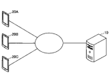
- FIG. 1 is a diagram illustrating a configuration of a communication system 1 according to an embodiment.
- the communication system 1 has a server 10, a terminal 20A, a terminal 20B, and a terminal 20C (hereinafter, when it is not necessary to distinguish them, it is simply referred to as a "terminal 20").
- the number of terminals 20 is not limited to the example of FIG.
- the server 10 and the terminal 20 are examples of "information processing devices", respectively.
- the terminal 20 and the server 10 are, for example, 5G (5th Generation, 5th generation mobile communication system), 4G, LTE (LongTermEvolution), 3G and other mobile phone networks, wireless LAN (Local Area Network), the Internet, etc. Communicates via the network N of.
- the server 10 is, for example, an information processing device such as a server.
- the terminal 20 is an information processing device such as a smartphone, a tablet, or a notebook personal computer.
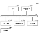
- FIG. 2 is a diagram illustrating a hardware configuration example of the server 10 and the terminal 20 according to the embodiment.
- the server 10 will be described as an example.
- the hardware configuration of the terminal 20 may be the same as that of the server 10.
- the server 10 has a drive device 1000, an auxiliary storage device 1002, a memory device 1003, a CPU 1004, an interface device 1005, and the like, which are connected to each other by a bus B, respectively.
- the information processing program that realizes the processing on the server 10 may be provided by the recording medium 1001.
- the recording medium 1001 on which the information processing program is recorded is set in the drive device 1000, the information processing program is installed in the auxiliary storage device 1002 from the recording medium 1001 via the drive device 1000.
- the information processing program does not necessarily have to be installed from the recording medium 1001, and may be downloaded from another computer via the network.
- the auxiliary storage device 1002 stores the installed information processing program and also stores necessary files, data, and the like.
- the memory device 1003 reads and stores the program from the auxiliary storage device 1002 when there is an instruction to start the program.
- the CPU 1004 executes the process according to the program stored in the memory device 1003.
- the interface device 1005 is used as an interface for connecting to a network.
- An example of the recording medium 1001 is a portable recording medium such as a CD-ROM, a DVD disc, or a USB memory. Further, as an example of the auxiliary storage device 1002, an HDD (Hard Disk Drive), a flash memory, or the like can be mentioned. Both the recording medium 1001 and the auxiliary storage device 1002 correspond to computer-readable recording media.
- the server 10 may be realized by an integrated circuit such as an ASIC (Application Specific Integrated Circuit) or an FPGA (Field-Programmable Gate Array).
- ASIC Application Specific Integrated Circuit
- FPGA Field-Programmable Gate Array
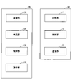
- FIG. 3 is a diagram showing an example of the configuration of the server 10 and the terminal 20 according to the embodiment.
- the server 10 has a communication unit 11, a control unit 12, and a storage unit 13. Each of these parts may be realized by the cooperation of one or more programs installed in the server 10 and hardware such as the CPU 1004 of the server 10.
- the communication unit 11 transmits / receives data to / from an external device such as a terminal 20.
- the control unit 12 provides various services to the terminal 20.
- the control unit 12 may provide, for example, a scheduler function for managing a user's schedule.
- the storage unit 13 stores various data according to the instructions of the control unit 12.
- Terminal 20 has an acquisition unit 21, a determination unit 22, a control unit 23, and a communication unit 24. Each of these parts may be realized by the cooperation of one or more programs installed in the terminal 20 and hardware such as a CPU of the terminal 20.
- the acquisition unit 21 acquires various types of information.
- the determination unit 22 makes various determinations based on the information acquired by the acquisition unit 21.
- the control unit 23 executes various processes based on the processing results of the determination unit 22.
- the communication unit 24 transmits / receives data to / from an external device such as a server 10 according to an instruction from the control unit 23.
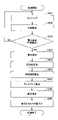
- FIGS. 4A to 7 are flowcharts illustrating an example of processing of the terminal 20 according to the embodiment.
- the communication system 1 according to the embodiment can execute the processes described with reference to FIGS. 4A to 4D in combination as appropriate.
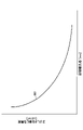
- FIG. 5 is a diagram illustrating an example of a model of luminance with respect to the diameter of the user's pupil according to the embodiment.
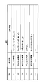
- FIG. 6A is a diagram illustrating an example of notification content according to the degree of fatigue according to the embodiment.
- the determination unit 22 detects (detects) that the display screen is transitioned (screen transition occurs) in the display device (display) of the terminal 20.
- the determination unit 22 may detect, for example, that authentication by a face, a fingerprint, a passcode, or the like for unlocking is performed. Further, the determination unit 22 may detect, for example, that an operation for displaying the setting screen (setup screen) of the terminal 20 has been accepted from the user. Further, the determination unit 22 may detect, for example, that the user has accepted an operation to start the application installed in the terminal 20. Further, in the determination unit 22, for example, when the second application is started by the first application installed in the terminal 20, the application displayed on the screen of the terminal 20 is switched from the first application to the second application. You may detect that.
- the change in brightness of the display of the terminal 20 at the time of screen transition can be used as a light stimulus for light reflex. Therefore, it is possible to reduce the burden (troublesomeness) of sensing on the user.
- the determination unit 22 detects the user's pupil (step S102) and measures the pupil diameter (pupil size) (step S103).
- the determination unit 22 acquires an image taken by the visible light camera, the near-infrared camera, or the like of the terminal 20 by the acquisition unit 21, detects the user's pupil, and determines the diameter of the pupil based on the acquired image. Measurement may be performed.
- the determination unit 22 estimates an appropriate luminance (an example of "first luminance") of the display device based on the diameter of the pupil of the user (step S104). This makes it possible to estimate an appropriate luminance (brightness) according to the diameter of the user's pupil due to ambient light or the like.
- the determination unit 22 uses, for example, the relational expression between the pupil diameter Dp [mm] and the luminance Ip [cd / m 2 ] of the following equation (1), and uses an appropriate luminance Ip according to the pupil diameter Dp of the user. May be determined.
- the determination unit 22 may calculate the luminance not far from the appropriate luminance Ip calculated by the equation (1) as the appropriate luminance.
- the determination unit 22 is based on a luminance model that feels glare with respect to the user's pupil diameter Dp (initial pupil diameter) when starting to use the display of the terminal 20, as shown by the curve 501 in FIG.
- the appropriate brightness may be determined.
- control unit 23 causes the display device or the like to emit light with an appropriate brightness estimated by the determination unit 22, and gives an appropriate light stimulus to the user (step S105).
- the control unit 23 displays the display screen after the transition with an appropriate brightness estimated by the determination unit 22.
- the control unit 23 changes the setting of the brightness value of the display screen from the default brightness to the first brightness by using, for example, an API (Application Programming Interface) provided by the OS (Operating System) of the terminal 20. You may.
- API Application Programming Interface
- the determination unit 22 estimates the user's fatigue level (stress level, non-relaxation level, emotion) (an example of the "user state") based on the change in the diameter of the user's pupil due to the light stimulus. (Step S106).
- the determination unit 22 first repeatedly executes the same processing as in steps S102 and S103, and values related to the change in the diameter of the user's pupil due to the light stimulus (for example, maximum miosis speed, average miosis speed, etc.). Miosis rate) is calculated. Then, the determination unit 22 estimates the degree of fatigue of the user based on the change in the diameter of the pupil of the user.
- the pupil is an organ that reflects the autonomic nervous activity, and it is said that the maximum miotic velocity in the light reflex is related to the parasympathetic nerve activity, and the maximum diastolic velocity is related to the sympathetic nerve activity. It has been. Therefore, it is considered that the autonomic nervous activity of the user can be estimated by utilizing this property.
- the determination unit 22 may determine, for example, that the larger the maximum miosis speed, the average miosis speed, and the miosis rate, the higher the degree of fatigue.
- the determination unit 22 may calculate a relative increase / decrease in the miosis speed or the like by comparing the change speed of the pupil diameter in the past of the user with the change speed of the diameter of the pupil this time. Then, the determination unit 22 may determine whether the parasympathetic nerve activity is relatively activated or deactivated at the present time based on this.
- the brightness of the display of the terminal 20 is set to give a light stimulus to the user, and the miosis reaction of the user is measured to cause fatigue of the user.
- the degree (fatigue state) can be measured.
- the determination unit 22 determines the notification content (message) according to the degree of fatigue of the user (step S107). Subsequently, the control unit 23 notifies the user of the notification content (step S108). Thereby, for example, it is possible to give a notification according to the degree of fatigue while reducing the mental burden on the user by measuring the degree of fatigue or the like. Further, since the push notification is performed from the terminal 20 when the screen transition in the terminal 20 occurs, it is possible to reduce the annoyance for the notification.
- a recommended action is notified by a message that encourages exercise habits such as "Let's walk for 15 minutes" according to the degree of fatigue of the user. You can also do it.
- the control unit 23 may notify the user of the notification content by voice or a display screen, for example.
- FIG. 6A shows an example of the notification content according to the degree of fatigue. In the example of FIG. 6A, an example of the notification content for resolving the lack of exercise is shown, but other notification content that encourages an action, a notification content that aims at a tired user, or the like may be used.
- control unit 23 may return the brightness of the display screen of the terminal 20 to the brightness (default brightness) before the change in the process of step S105 in the process of step S108.
- the determination unit 22 determines the content of the notification based on what can be estimated from the autonomic nervous activity information such as the stress level, the relaxation level, and the emotion. You may decide.
- Example of estimating the degree of fatigue by applying a light stimulus with brightness set to the pupil at the time of screen transition >> Next, with reference to FIG. 4B, an example in which a light stimulus whose brightness is set at the time of screen transition is applied to the pupil to estimate the degree of fatigue and the like will be described.
- step S201 the acquisition unit 21 acquires (sensing) various data from various sensors of the terminal 20 or an external sensor (for example, a wearable sensor).
- the acquisition unit 21 may acquire data measured by, for example, the GPS (Global Positioning System) of the terminal 20 and the acceleration sensor.
- GPS Global Positioning System
- the determination unit 22 estimates the user's task (behavior) based on various data acquired by the acquisition unit 21 (step S202).
- the determination unit 22 calculates, for example, the user's position information and the movement speed, and if the user's position information is on the track and the movement speed is about the same as the movement speed of the train, the task performed by the user. May be presumed to be a train movement.
- the determination unit 22 may estimate the user's behavior based on the schedule information set in the scheduler (schedule management application) of the terminal 20, for example.
- the determination unit 22 determines whether or not a screen transition occurs in the display device of the terminal 20 (step S203). If no screen transition occurs (NO in step S203), the process proceeds to step S201.
- step S203 if the screen transition does not occur (YES in step S203), the process proceeds to step S201.
- the determination unit 22 detects the user's pupil (step S204) and measures the diameter of the pupil (step S205). Subsequently, the determination unit 22 estimates an appropriate luminance of the display device based on the diameter of the pupil of the user (step S206). Subsequently, the control unit 23 causes the display device or the like to emit light with an appropriate brightness estimated by the determination unit 22, and gives an appropriate light stimulus to the user (step S207). Subsequently, the determination unit 22 estimates the degree of fatigue of the user based on the change in the diameter of the pupil of the user due to the light stimulus (step S208).
- step S203 to step S208 may be the same as each process from step S101 to step S106 in FIG. 4A.
- control unit 23 associates the user's fatigue level estimated by the determination unit 22 in step S208 with the user's task estimated by the determination unit 22 in step S202 and records it on the server 10 or the like (step S209). ).
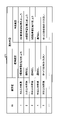
- FIG. 6B is a diagram illustrating an example of notification content according to the degree of fatigue and the type of fatigue according to the embodiment.
- step S301 the determination unit 22 detects that a screen transition occurs in the display device of the terminal 20. Subsequently, the determination unit 22 detects the user's pupil (step S302) and measures the diameter of the pupil (step S303). Subsequently, the determination unit 22 estimates an appropriate luminance of the display device based on the diameter of the pupil of the user (step S304). Subsequently, the control unit 23 causes the display device or the like to emit light with an appropriate brightness estimated by the determination unit 22, and gives an appropriate light stimulus to the user (step S305). Subsequently, the determination unit 22 estimates the degree of fatigue of the user based on the change in the diameter of the pupil of the user due to the light stimulus (step S306). The processes of steps S301 to S306 may be the same as the processes of steps S101 to S106 of FIG. 4A.
- the determination unit 22 estimates the type of fatigue of the user (step S307).
- the determination unit 22 determines whether the user's fatigue is mental fatigue or physical fatigue based on the task currently being executed by the user.
- the determination unit 22 may determine the task currently being executed by the user, for example, by the same processing as in steps S201 and S202 of FIG. 4B.
- the determination unit 22 determines the notification content according to the degree of fatigue of the user and the type of fatigue (step S308).
- the control unit 23 notifies the user of the notification content (step S309).
- the control unit 23 may notify the user of the notification content by voice or a display screen, for example.
- FIG. 6B shows an example of the notification content according to the degree of fatigue and the type of fatigue.
- FIG. 6B an example of urging the user to memorize English words as a recommended action is shown.
- recommended behavior that uses the head such as memorizing English words, it is possible to perform the recommended behavior if the person is physically tired rather than mentally tired even if the degree of fatigue is the same. It is considered to have high sex.
- FIG. 4C for example, an appropriate message can be notified to the user for each type of fatigue even if the fatigue level is the same.
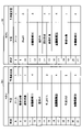
- FIG. 7 is a diagram illustrating an example of a schedule and an expected fatigue level of each user according to the embodiment.
- step S401 the acquisition unit 21 acquires the task schedule of one or more users from the scheduler.
- the acquisition unit 21 acquires information on the degree of fatigue of each task (step S402).
- the acquisition unit 21 may acquire, for example, the data recorded in the server 10 by the process of FIG. 4B, in which the user's fatigue level and the user's task are associated with each other.
- the determination unit 22 estimates the fatigue level for each user's schedule based on the task schedule of each user and the information on the fatigue level of each task (step S403).
- the determination unit 22 detects that the application (scheduling system) for setting scheduling has been started (step S404).
- the determination unit 22 detects (determines, selects) one or more candidate dates and times based on the schedule of each user set in the scheduler (step S405).
- the determination unit 22 may select one or more candidate date / time from the unscheduled date / time of each user set as a conference participant, for example.
- the determination unit 22 estimates the degree of fatigue of each user immediately before each candidate date and time (step S406). Subsequently, the determination unit 22 recommends (suggests) to the user the date and time when the fatigue level of each user is equal to or less than the threshold value among the candidate dates and times (step S407).
- FIG. 7 shows the task scheduled at each time of user A (Mr. A), the information 701 of the predicted fatigue level (predicted fatigue level), and the task scheduled at each time of user B (Mr. B).
- An example with expected fatigue information 702 is shown.
- the conference holding date and time is adjusted between the user A and the user B set as the conference participants, the time zone in which the user A and the user B have no schedule is detected as the candidate date and time.
- the first candidate date and time 11:00 to 13:00, the second candidate date and time 16:00 to 18:00, and the third candidate date and time 20:00 to 22:00 are detected.
- the fatigue level of the task immediately before the time zone of each candidate date and time is estimated (predicted).
- a second candidate date and time which is a date and time when the degree of fatigue is not high immediately before the candidate date and time of all the conference participants, is proposed.
- the user can schedule a meeting with all employees in the same department at the optimum date and time based on the expected fatigue level of each employee's schedule. Therefore, it is possible to perform scheduling that improves the productivity of a plurality of users as a whole.
- the target of scheduling is an individual rather than multiple people, it is possible to recommend a schedule that does not continue tasks with a high degree of fatigue within the individual.
- each functional unit of the terminal 20 may be realized by, for example, cloud computing provided by one or more computers.
- the determination unit 22 or the like may be provided on the server 10 or the like.
- Communication system 10 Server 11 Communication unit 12 Control unit 13 Storage unit 20 Terminal 21 Acquisition unit 22 Judgment unit 23 Control unit 24 Communication unit
Landscapes
- Health & Medical Sciences (AREA)
- Life Sciences & Earth Sciences (AREA)
- Engineering & Computer Science (AREA)
- Hospice & Palliative Care (AREA)
- Pathology (AREA)
- Developmental Disabilities (AREA)
- Psychiatry (AREA)
- Psychology (AREA)
- Social Psychology (AREA)
- Physics & Mathematics (AREA)
- Child & Adolescent Psychology (AREA)
- Biophysics (AREA)
- Educational Technology (AREA)
- Biomedical Technology (AREA)
- Heart & Thoracic Surgery (AREA)
- Medical Informatics (AREA)
- Molecular Biology (AREA)
- Surgery (AREA)
- Animal Behavior & Ethology (AREA)
- General Health & Medical Sciences (AREA)
- Public Health (AREA)
- Veterinary Medicine (AREA)
- Eye Examination Apparatus (AREA)
Abstract
情報処理装置が、表示画面が遷移されることを検知した際のユーザの瞳孔の大きさに応じた第1輝度で遷移後の表示画面を表示させる処理と、遷移後の表示画面が前記第1輝度で表示された際の前記ユーザの瞳孔の大きさの変化に基づいて、前記ユーザの状態を判定する処理と、を実行する。
Description
本開示は、情報処理方法、情報処理装置、及びプログラムに関する。
近年、自律神経活動を推定するシステムの研究開発が多く行われている。日常的に自律神経活動を推定するシステムとしては、ユーザの手間を省くため、接触センサを用いて、ユーザが意識することなく推定を行う技術の検討もされている(例えば、特許文献1、2、3を参照)。
しかしながら、従来技術では、接触センサを用いたセンシングによる負担感をユーザに感じさせる場合がある。
一側面では、センシングによるユーザの負担感を低減できる技術を提供することを目的とする。
一つの案では、情報処理装置が、表示画面が遷移されることを検知した際のユーザの瞳孔の大きさに応じた第1輝度で遷移後の表示画面を表示させる処理と、遷移後の表示画面が前記第1輝度で表示された際の前記ユーザの瞳孔の大きさの変化に基づいて、前記ユーザの状態を判定する処理と、を実行する。
一側面によれば、センシングによるユーザの負担感を低減することができる。
以下、図面を参照して、本開示の実施形態を説明する。
<全体構成>
図1は、実施形態に係る通信システム1の構成について説明する図である。図1の例では、通信システム1は、サーバ10、端末20A、端末20B、端末20C(以下で、区別する必要が無い場合は、単に「端末20」と称する。)を有する。なお、端末20の数は図1の例に限定されない。なお、サーバ10、及び端末20は、それぞれ、「情報処理装置」の一例である。
図1は、実施形態に係る通信システム1の構成について説明する図である。図1の例では、通信システム1は、サーバ10、端末20A、端末20B、端末20C(以下で、区別する必要が無い場合は、単に「端末20」と称する。)を有する。なお、端末20の数は図1の例に限定されない。なお、サーバ10、及び端末20は、それぞれ、「情報処理装置」の一例である。
端末20とサーバ10とは、例えば、5G(5th Generation、第5世代移動通信システム)、4G、LTE(Long Term Evolution)、3G等の携帯電話網、無線LAN(Local Area Network)、及びインターネット等のネットワークNを介して通信を行う。
サーバ10は、例えば、サーバ等の情報処理装置である。端末20は、例えば、スマートフォン、タブレット、ノート型パーソナルコンピュータ等の情報処理装置である。
<サーバ10及び端末20のハードウェア構成>
図2は、実施形態に係るサーバ10及び端末20のハードウェア構成例について説明する図である。以下では、サーバ10を例として説明する。端末20のハードウェア構成は、サーバ10と同様でもよい。
図2は、実施形態に係るサーバ10及び端末20のハードウェア構成例について説明する図である。以下では、サーバ10を例として説明する。端末20のハードウェア構成は、サーバ10と同様でもよい。
図2の例では、サーバ10は、それぞれバスBで相互に接続されているドライブ装置1000、補助記憶装置1002、メモリ装置1003、CPU1004、及びインタフェース装置1005等を有する。
サーバ10での処理を実現する情報処理プログラムは、記録媒体1001によって提供されてもよい。この場合、情報処理プログラムを記録した記録媒体1001がドライブ装置1000にセットされると、情報処理プログラムが記録媒体1001からドライブ装置1000を介して補助記憶装置1002にインストールされる。但し、情報処理プログラムのインストールは必ずしも記録媒体1001より行う必要はなく、ネットワークを介して他のコンピュータよりダウンロードするようにしてもよい。補助記憶装置1002は、インストールされた情報処理プログラムを格納すると共に、必要なファイルやデータ等を格納する。
メモリ装置1003は、プログラムの起動指示があった場合に、補助記憶装置1002からプログラムを読み出して格納する。CPU1004は、メモリ装置1003に格納されたプログラムに従って処理を実行する。インタフェース装置1005は、ネットワークに接続するためのインタフェースとして用いられる。
なお、記録媒体1001の一例としては、CD-ROM、DVDディスク、又はUSBメモリ等の可搬型の記録媒体が挙げられる。また、補助記憶装置1002の一例としては、HDD(Hard Disk Drive)又はフラッシュメモリ等が挙げられる。記録媒体1001及び補助記憶装置1002のいずれについても、コンピュータ読み取り可能な記録媒体に相当する。
なお、サーバ10は、例えば、ASIC(Application Specific Integrated Circuit)またはFPGA(Field-Programmable Gate Array)等の集積回路により実現されてもよい。
<サーバ10及び端末20の構成>
次に、図3を参照し、実施形態に係るサーバ10及び端末20の構成について説明する。図3は、実施形態に係るサーバ10及び端末20の構成の一例を示す図である。
次に、図3を参照し、実施形態に係るサーバ10及び端末20の構成について説明する。図3は、実施形態に係るサーバ10及び端末20の構成の一例を示す図である。
《サーバ10》
サーバ10は、通信部11、制御部12、及び記憶部13を有する。これら各部は、サーバ10にインストールされた1以上のプログラムと、サーバ10のCPU1004等のハードウェアとの協働により実現されてもよい。
サーバ10は、通信部11、制御部12、及び記憶部13を有する。これら各部は、サーバ10にインストールされた1以上のプログラムと、サーバ10のCPU1004等のハードウェアとの協働により実現されてもよい。
通信部11は、端末20等の外部装置とのデータの送受信を行う。制御部12は、端末20に各種のサービスを提供する。制御部12は、例えば、ユーザのスケジュールを管理するスケジューラ機能を提供してもよい。記憶部13は、制御部12の指示に従い各種のデータを記憶する。
《端末20》
端末20は、取得部21、判定部22、制御部23、及び通信部24を有する。これら各部は、端末20にインストールされた1以上のプログラムと、端末20のCPU等のハードウェアとの協働により実現されてもよい。
端末20は、取得部21、判定部22、制御部23、及び通信部24を有する。これら各部は、端末20にインストールされた1以上のプログラムと、端末20のCPU等のハードウェアとの協働により実現されてもよい。
取得部21は、各種の情報を取得する。判定部22は、取得部21に取得された情報に基づいて、各種の判定を行う。制御部23は、判定部22による処理結果に基づいて各種の処理を実行する。通信部24は、制御部23の指示に従い、サーバ10等の外部装置とのデータの送受信を行う。
<処理>
次に、図4Aから図7を参照し、実施形態に係る端末20の処理の一例について説明する。図4Aから図4Dは、実施形態に係る端末20の処理の一例について説明するフローチャートである。なお、実施形態に係る通信システム1は、以下の図4Aから図4Dで説明する各処理を、適宜組み合わせて実行できる。
次に、図4Aから図7を参照し、実施形態に係る端末20の処理の一例について説明する。図4Aから図4Dは、実施形態に係る端末20の処理の一例について説明するフローチャートである。なお、実施形態に係る通信システム1は、以下の図4Aから図4Dで説明する各処理を、適宜組み合わせて実行できる。
《画面遷移時に輝度設定された光刺激を瞳孔に与えて疲労度等を推定する例》
図4A、図5、図6Aを参照し、画面遷移時に輝度設定された光刺激を瞳孔に与えて疲労度等を推定する例について説明する。図5は、実施形態に係るユーザの瞳孔の径に対する輝度のモデルの一例について説明する図である。図6Aは、実施形態に係る疲労度に応じた通知内容の一例について説明する図である。
図4A、図5、図6Aを参照し、画面遷移時に輝度設定された光刺激を瞳孔に与えて疲労度等を推定する例について説明する。図5は、実施形態に係るユーザの瞳孔の径に対する輝度のモデルの一例について説明する図である。図6Aは、実施形態に係る疲労度に応じた通知内容の一例について説明する図である。
ステップS101において、判定部22は、端末20の表示デバイス(ディスプレイ)において表示画面が遷移されること(画面遷移が発生すること)を検出(検知)する。ここで、判定部22は、例えば、ロックを解除するための顔、指紋、またはパスコード等による認証が行われることを検出してもよい。また、判定部22は、例えば、端末20の設定画面(セットアップ画面)が表示される操作をユーザから受け付けたことを検出してもよい。また、判定部22は、例えば、端末20にインストールされているアプリケーションを起動する操作をユーザから受け付けたことを検出してもよい。また、判定部22は、例えば、端末20にインストールされている第1アプリケーションにより第2アプリケーションが起動されることにより、端末20の画面に表示されるアプリケーションが第1アプリケーションから第2アプリケーションに切り替えられることを検出してもよい。
これにより、例えば、画面遷移時の端末20のディスプレイの輝度変化を対光反射の光刺激として利用することができる。そのため、ユーザに対するセンシングによる負担感(煩わしさ)を低減できる。
続いて、判定部22は、ユーザの瞳孔を検出し(ステップS102)、瞳孔の径(瞳孔の大きさ)の計測を行う(ステップS103)。ここで、判定部22は、端末20の可視光カメラまたは近赤外線カメラ等により撮影された画像を取得部21により取得し、取得した画像に基づいて、ユーザの瞳孔の検出、及び瞳孔の径の計測を行ってもよい。
続いて、判定部22は、ユーザの瞳孔の径に基づいて、表示デバイスの適切な輝度(「第1輝度」の一例。)を推定する(ステップS104)。これにより、環境光等によるユーザの瞳孔の径に応じた適切な輝度(明るさ)を推定できる。
なお、縮瞳反応を計測するための光刺激としてディスプレイを明るくし過ぎると、ユーザにとって煩わしくなる。そのため、こうした煩わしさを軽減するためにユーザの瞳孔径に基づいた適切な明るさの光刺激を与える。
判定部22は、例えば、以下の式(1)の瞳孔径Dp[mm]と輝度Ip[cd/m2]との関係式を用いて、ユーザの瞳孔の径Dpに応じた適切な輝度Ipを決定してもよい。

続いて、制御部23は、判定部22により推定された適切な輝度で表示デバイス等を発光させ、ユーザに適切な光刺激を与える(ステップS105)。ここで、制御部23は、遷移後の表示画面を、判定部22により推定された適切な輝度で表示させる。この場合、制御部23は、例えば、端末20のOS(Operating System)により提供されるAPI(Application Programming Interface)を用いて、表示画面の輝度の値の設定をデフォルトの輝度から第1輝度に変更してもよい。
続いて、判定部22は、当該光刺激によるユーザの瞳孔の径の変化に基づいて、ユーザの疲労度(ストレス度、非リラックス度、情動)(「ユーザの状態」の一例。)を推定する(ステップS106)。ここで、判定部22は、まず、ステップS102及びステップS103と同様の処理を繰り返し実行し、当該光刺激によるユーザの瞳孔の径の変化に関する値(例えば、最大縮瞳速度、平均縮瞳速度、縮瞳率)を算出する。そして、判定部22は、ユーザの瞳孔の径の変化に基づいて、ユーザの疲労度を推定する。なお、瞳孔は自律神経活動を反映する器官であり、対光反射における最大縮瞳速度は副交感神経活動と関係があると言われており、最大散大速度が交感神経活動と関係があると言われている。そのため、この性質を利用してユーザの自律神経活動を推定できると考えられる。
判定部22は、例えば、最大縮瞳速度、平均縮瞳速度、及び縮瞳率が大きいほど、疲労度が高いと判定してもよい。
また、判定部22は、ユーザの過去の瞳孔の径の変化速度と、今回の瞳孔の径の変化速度とを比較することにより、相対的な縮瞳速度等の増減を算出してもよい。そして、判定部22は、これを基に現時点において相対的に副交感神経活動が活性化しているか、もしくは非活性化しているかを判定してもよい。
これにより、例えば、端末20の表示画面が遷移(変化)する際に端末20のディスプレイの輝度を設定することによってユーザに光刺激を与え、ユーザの縮瞳反応を計測することにより、ユーザの疲労度(疲労状態)を測定することができる。
続いて、判定部22は、ユーザの疲労度に応じた通知内容(メッセージ)を決定する(ステップS107)。続いて、制御部23は、当該通知内容をユーザに通知する(ステップS108)。これにより、例えば、疲労度等の測定によるユーザの心的負担を低減しながら疲労度等に応じた通知を行うことができる。また、端末20での画面遷移が発生する際に端末20からのプッシュ通知が行われるため、当該通知に対する煩わしさを軽減できる。また、例えば、運動不足のユーザに対してスマートフォン等を開いた等の際に、ユーザの疲労度に応じて「15分歩きましょう」等の運動習慣を促すようなメッセージにより推奨行動を通知することもできる。
ここで、制御部23は、例えば、音声、または表示画面により、当該通知内容をユーザに通知してもよい。図6Aには、疲労度に応じた通知内容の一例が示されている。図6Aの例では、運動不足解消のための通知内容の例が示されているが、その他の行動を促す通知内容、及び疲れているユーザをねぎらう通知内容等でもよい。
また、制御部23は、ステップS108の処理において、端末20の表示画面の輝度を、ステップS105の処理で変更する前の輝度(デフォルトの輝度)に戻してもよい。
なお、上述した例では、疲労度を用いる例について説明したが、判定部22は、ストレス度、リラックス度、情動など自律神経活動情報から推定できるものであれば、何を基にして通知内容を決定してもよい。
《画面遷移時に輝度設定された光刺激を瞳孔に与えて疲労度等を推定する例》
次に、図4Bを参照し、画面遷移時に輝度設定された光刺激を瞳孔に与えて疲労度等を推定する例について説明する。
次に、図4Bを参照し、画面遷移時に輝度設定された光刺激を瞳孔に与えて疲労度等を推定する例について説明する。
ステップS201において、取得部21は、端末20の各種センサまたは外部センサ(例えば、ウェアラブルセンサ)による各種データを取得(センシング)する。ここで、取得部21は、例えば、端末20のGPS(Global Positioning System)、及び加速度センサで測定されたデータを取得してもよい。
続いて、判定部22は、取得部21により取得された各種データに基づいて、ユーザのタスク(行動)を推定する(ステップS202)。ここで、判定部22は、例えば、ユーザの位置情報と移動速度とを算出し、ユーザの位置情報が線路上で移動速度が電車の移動速度と同程度であれば、ユーザが行っているタスクを電車移動であるといった推定を行ってもよい。
また、判定部22は、例えば、端末20のスケジューラ(スケジュール管理アプリケーション)等に設定されているスケジュール情報に基づいて、ユーザの行動を推定してもよい。
続いて、判定部22は、端末20の表示デバイスにおいて画面遷移が発生するか否かを判定する(ステップS203)。画面遷移が発生しない場合(ステップS203でNO)、ステップS201の処理に進む。
一方、画面遷移が発生しない場合(ステップS203でYES)、ステップS201の処理に進む。
続いて、判定部22は、ユーザの瞳孔を検出し(ステップS204)、瞳孔の径の計測を行う(ステップS205)。続いて、判定部22は、ユーザの瞳孔の径に基づいて、表示デバイスの適切な輝度を推定する(ステップS206)。続いて、制御部23は、判定部22により推定された適切な輝度で表示デバイス等を発光させ、ユーザに適切な光刺激を与える(ステップS207)。続いて、判定部22は、当該光刺激によるユーザの瞳孔の径の変化に基づいて、ユーザの疲労度を推定する(ステップS208)。
なお、ステップS203からステップS208の各処理は、図4AのステップS101からステップS106の各処理とそれぞれ同様でもよい。
続いて、制御部23は、ステップS208で判定部22により推定されたユーザの疲労度と、ステップS202で判定部22により推定されたユーザのタスクとを関連付けてサーバ10等に記録させる(ステップS209)。
これにより、例えば、自律神経活動の変化とともに、その変化が生じた際に実施していたタスク、すなわち自律神経活動の変化の原因となったタスクを併せて保持して学習することにより、タスクごとの疲労情報を推定することが可能となる。
《疲労度と疲労の種類を推定する例》
次に、図4C及び図6Bを参照し、疲労度と疲労の種類を推定する例について説明する。図6Bは、実施形態に係る疲労度と疲労の種類とに応じた通知内容の一例について説明する図である。
次に、図4C及び図6Bを参照し、疲労度と疲労の種類を推定する例について説明する。図6Bは、実施形態に係る疲労度と疲労の種類とに応じた通知内容の一例について説明する図である。
ステップS301において、判定部22は、端末20の表示デバイスにおいて画面遷移が発生することを検出する。続いて、判定部22は、ユーザの瞳孔を検出し(ステップS302)、瞳孔の径の計測を行う(ステップS303)。続いて、判定部22は、ユーザの瞳孔の径に基づいて、表示デバイスの適切な輝度を推定する(ステップS304)。続いて、制御部23は、判定部22により推定された適切な輝度で表示デバイス等を発光させ、ユーザに適切な光刺激を与える(ステップS305)。続いて、判定部22は、当該光刺激によるユーザの瞳孔の径の変化に基づいて、ユーザの疲労度を推定する(ステップS306)。なお、ステップS301からステップS306の各処理は、図4AのステップS101からステップS106の各処理とそれぞれ同様でもよい。
続いて、判定部22は、ユーザの疲労の種類を推定する(ステップS307)。ここで、判定部22は、ユーザが現在実行しているタスクに基づいて、ユーザの疲労が精神疲労であるか肉体疲労であるかの判定を行う。判定部22は、例えば、図4BのステップS201及びステップS202と同様の処理により、ユーザが現在実行しているタスクを判定してもよい。
続いて、判定部22は、ユーザの疲労度と、疲労の種類とに応じた通知内容を決定する(ステップS308)。続いて、制御部23は、当該通知内容をユーザに通知する(ステップS309)。ここで、制御部23は、例えば、音声、または表示画面により、当該通知内容をユーザに通知してもよい。図6Bには、疲労度と疲労の種類とに応じた通知内容の一例が示されている。図6Bの例では、ユーザに推奨行動として英単語の暗記を促す例が示されている。英単語の暗記のような頭を使う推奨行動である場合、同じ疲労度であっても精神疲労をしている場合よりも、肉体疲労をしている場合である方が、推奨行動を行える可能性が高いと考えられる。図4Cの処理によれば、例えば、同じ疲労度であっても疲労の種類ごとに適切なメッセージをユーザに通知できる。
《予想疲労度に基づいて候補日を提案する例》
次に、図4D及び図7を参照し、予想疲労度に基づいて候補日を提案する例について説明する。図7は、実施形態に係る各ユーザのスケジュールと予想疲労度の一例について説明する図である。
次に、図4D及び図7を参照し、予想疲労度に基づいて候補日を提案する例について説明する。図7は、実施形態に係る各ユーザのスケジュールと予想疲労度の一例について説明する図である。
ステップS401において、取得部21は、1以上の各ユーザのタスクのスケジュールをスケジューラから取得する。
続いて、取得部21は、各タスクの疲労度の情報を取得する(ステップS402)。ここで、取得部21は、例えば、図4Bの処理によりサーバ10に記録されている、ユーザの疲労度とユーザのタスクとが関連付けられたデータを取得してもよい。
続いて、判定部22は、各ユーザのタスクのスケジュールと、各タスクの疲労度の情報とに基づいて、各ユーザのスケジュールに対する疲労度を推定する(ステップS403)。
続いて、判定部22は、スケジューリングを設定するアプリケーション(スケジューリングシステム)が起動されたことを検出する(ステップS404)。
続いて、判定部22は、スケジューラに設定されている各ユーザのスケジュールに基づいて、1以上の候補日時を検出(決定、選択)する(ステップS405)。ここで、判定部22は、例えば、会議参加者として設定された各ユーザの予定のない日時から、1以上の候補日時を選択してもよい。
続いて、判定部22は、各候補日時の直前における各ユーザの疲労度をそれぞれ推定する(ステップS406)。続いて、判定部22は、各候補日時のうち、各ユーザの疲労度が閾値以下である日時をユーザに推薦(提案)する(ステップS407)。
図7には、ユーザA(Aさん)の各時刻に予定されているタスクと予想疲労度(予測疲労度)の情報701と、ユーザB(Bさん)の各時刻に予定されているタスクと予想疲労度の情報702との例が示されている。会議参加者として設定されたユーザAとユーザBとで会議開催日時を調整する場合、ユーザAとユーザBとで予定がない時間帯を候補日時として検出する。図7の例では、第1候補日時11:00~13:00、第2候補日時16:00~18:00、第3候補日時20:00~22:00が検出される。そして、各候補日時の時間帯の直前のタスクの疲労度が推定(予測)される。そして、全ての会議参加者の候補日時直前の疲労度が高くない日時である第2候補日時が提案される。
これにより、例えば、ユーザが同じ部署等の従業員全員での会議を各従業員のスケジュールによる予想疲労度に基づいて最適な日時にスケジューリングすることができる。そのため、複数のユーザの全体として生産性が向上するスケジューリングが可能となる。
また、スケジューリングの対象が複数人でなく個人である場合は、個人内における疲労度が高いタスクを連続させないスケジュールを推薦できる。
<変形例>
端末20の各機能部のうち少なくとも一部は、例えば1以上のコンピュータにより提供されるクラウドコンピューティング等により実現されていてもよい。この場合、例えば、判定部22等をサーバ10等に設けてもよい。
端末20の各機能部のうち少なくとも一部は、例えば1以上のコンピュータにより提供されるクラウドコンピューティング等により実現されていてもよい。この場合、例えば、判定部22等をサーバ10等に設けてもよい。
以上、本発明の実施例について詳述したが、本発明は斯かる特定の実施形態に限定されるものではなく、特許請求の範囲に記載された本発明の要旨の範囲内において、種々の変形・変更が可能である。
1 通信システム
10 サーバ
11 通信部
12 制御部
13 記憶部
20 端末
21 取得部
22 判定部
23 制御部
24 通信部
10 サーバ
11 通信部
12 制御部
13 記憶部
20 端末
21 取得部
22 判定部
23 制御部
24 通信部
Claims (7)
- 情報処理装置が、
表示画面が遷移されることを検知した際のユーザの瞳孔の大きさに応じた第1輝度で遷移後の表示画面を表示させる処理と、
遷移後の表示画面が前記第1輝度で表示された際の前記ユーザの瞳孔の大きさの変化に基づいて、前記ユーザの状態を判定する処理と、
を実行する情報処理方法。 - 前記ユーザの状態を判定する処理では、
表示画面が前記第1輝度で表示された際の前記ユーザの瞳孔の大きさの変化に基づいて前記ユーザの疲労度を推定し、推定した疲労度に応じたメッセージを通知する、
請求項1に記載の情報処理方法。 - 前記ユーザの状態を判定する処理では、
前記ユーザのタスクと、推定した前記ユーザの状態とを関連付ける、
請求項1または2に記載の情報処理方法。 - 前記ユーザの状態を判定する処理では、
表示画面が前記第1輝度で表示された際の前記ユーザの瞳孔の大きさの変化に基づいて前記ユーザの疲労度を推定し、
前記ユーザのタスクに基づいて、前記ユーザの疲労の種類を推定し、
疲労度と疲労の種類とに応じたメッセージを通知する、
請求項1から3のいずれか一項に記載の情報処理方法。 - 前記情報処理装置が、
表示画面が前記第1輝度で表示された際の前記ユーザの瞳孔の大きさの変化に基づいて推定された前記ユーザの状態と前記ユーザのタスクとが関連付けされた情報と、各ユーザのスケジュールに含まれる各時刻のタスクとに基づいて、当該各ユーザの各時刻における状態を推定する処理と、
推定した当該各ユーザの各時刻における状態に基づいて、当該各ユーザに対する所定のタスクの日時を選択する処理と、を実行する、
請求項1から4のいずれか一項に記載の情報処理方法。 - 表示画面が遷移されることを検知した際のユーザの瞳孔の大きさに応じた第1輝度で遷移後の表示画面を表示させる処理と、
遷移後の表示画面が前記第1輝度で表示された際の前記ユーザの瞳孔の大きさの変化に基づいて、前記ユーザの状態を判定する処理と、
を実行する制御部を有する情報処理装置。 - 情報処理装置に、
表示画面が遷移されることを検知した際のユーザの瞳孔の大きさに応じた第1輝度で遷移後の表示画面を表示させる処理と、
遷移後の表示画面が前記第1輝度で表示された際の前記ユーザの瞳孔の大きさの変化に基づいて、前記ユーザの状態を判定する処理と、
を実行させるプログラム。
Priority Applications (1)
| Application Number | Priority Date | Filing Date | Title |
|---|---|---|---|
| PCT/JP2020/046127 WO2022123746A1 (ja) | 2020-12-10 | 2020-12-10 | 情報処理方法、情報処理装置、及びプログラム |
Applications Claiming Priority (1)
| Application Number | Priority Date | Filing Date | Title |
|---|---|---|---|
| PCT/JP2020/046127 WO2022123746A1 (ja) | 2020-12-10 | 2020-12-10 | 情報処理方法、情報処理装置、及びプログラム |
Publications (1)
| Publication Number | Publication Date |
|---|---|
| WO2022123746A1 true WO2022123746A1 (ja) | 2022-06-16 |
Family
ID=81973457
Family Applications (1)
| Application Number | Title | Priority Date | Filing Date |
|---|---|---|---|
| PCT/JP2020/046127 Ceased WO2022123746A1 (ja) | 2020-12-10 | 2020-12-10 | 情報処理方法、情報処理装置、及びプログラム |
Country Status (1)
| Country | Link |
|---|---|
| WO (1) | WO2022123746A1 (ja) |
Cited By (1)
| Publication number | Priority date | Publication date | Assignee | Title |
|---|---|---|---|---|
| JP2025059006A (ja) * | 2023-09-28 | 2025-04-09 | ソフトバンクグループ株式会社 | システム |
Citations (4)
| Publication number | Priority date | Publication date | Assignee | Title |
|---|---|---|---|---|
| WO2015072202A1 (ja) * | 2013-11-18 | 2015-05-21 | ソニー株式会社 | 瞳孔径に基づく眼の疲労検出のための情報処理装置、方法、およびプログラム |
| JP2015170099A (ja) * | 2014-03-06 | 2015-09-28 | ソニー株式会社 | 情報処理装置、情報処理方法、アイウェア端末および認証システム |
| US20160180801A1 (en) * | 2014-12-18 | 2016-06-23 | Samsung Electronics Co., Ltd. | Method and apparatus for controlling an electronic device |
| WO2016189711A1 (ja) * | 2015-05-27 | 2016-12-01 | 糧三 齋藤 | 携帯端末用ストレス評価プログラム及び該プログラムを備えた携帯端末 |
-
2020
- 2020-12-10 WO PCT/JP2020/046127 patent/WO2022123746A1/ja not_active Ceased
Patent Citations (4)
| Publication number | Priority date | Publication date | Assignee | Title |
|---|---|---|---|---|
| WO2015072202A1 (ja) * | 2013-11-18 | 2015-05-21 | ソニー株式会社 | 瞳孔径に基づく眼の疲労検出のための情報処理装置、方法、およびプログラム |
| JP2015170099A (ja) * | 2014-03-06 | 2015-09-28 | ソニー株式会社 | 情報処理装置、情報処理方法、アイウェア端末および認証システム |
| US20160180801A1 (en) * | 2014-12-18 | 2016-06-23 | Samsung Electronics Co., Ltd. | Method and apparatus for controlling an electronic device |
| WO2016189711A1 (ja) * | 2015-05-27 | 2016-12-01 | 糧三 齋藤 | 携帯端末用ストレス評価プログラム及び該プログラムを備えた携帯端末 |
Cited By (1)
| Publication number | Priority date | Publication date | Assignee | Title |
|---|---|---|---|---|
| JP2025059006A (ja) * | 2023-09-28 | 2025-04-09 | ソフトバンクグループ株式会社 | システム |
Similar Documents
| Publication | Publication Date | Title |
|---|---|---|
| US12320977B2 (en) | Display system | |
| EP3162041B1 (en) | Leveraging user signals for initiating communications | |
| JP7247308B2 (ja) | 身体活動及びトレーニングモニタ | |
| Vaizman et al. | Extrasensory app: Data collection in-the-wild with rich user interface to self-report behavior | |
| KR102606689B1 (ko) | 전자 장치에서 생체 정보 제공 방법 및 장치 | |
| US20160063874A1 (en) | Emotionally intelligent systems | |
| US9204836B2 (en) | Sporadic collection of mobile affect data | |
| US20170293727A1 (en) | Intelligent blood pressure monitoring | |
| US10559387B2 (en) | Sleep monitoring from implicitly collected computer interactions | |
| KR102319269B1 (ko) | 집단내의 스트레스 레벨 및 스트레스 내성 레벨의 프로파일을 생성하기 위한 시스템 및 방법 | |
| JP2018515155A (ja) | ウェアラブルデバイスを用いてユーザの良好さを遠隔からモニタするためのシステム、デバイス、及び方法 | |
| WO2019132772A1 (en) | Method and system for monitoring emotions | |
| CN106796707A (zh) | 慢性疾病发现和管理系统 | |
| US11687849B2 (en) | Information processing apparatus, information processing method, and program | |
| JP2020038542A (ja) | 情報処理装置、情報処理方法及びプログラム | |
| Rana et al. | Opportunistic and context-aware affect sensing on smartphones: the concept, challenges and opportunities | |
| US20200268299A1 (en) | State display apparatus, state display system, and non-transitory computer readable medium storing program | |
| WO2016110500A1 (en) | Scheduling interaction with a subject | |
| Haim et al. | The mobile photographic stress meter (MPSM) a new way to measure stress using images | |
| JP2020166593A (ja) | ユーザ支援装置、ユーザ支援方法及びユーザ支援プログラム | |
| JP7298821B2 (ja) | 情報処理システムおよびプログラム | |
| US20230368092A1 (en) | Dynamic calendar scheduling based upon user data | |
| JP7283561B2 (ja) | ストレス分析装置、ストレス分析方法、及びプログラム | |
| JP7840808B2 (ja) | 行動支援装置及び介入施策支援方法 | |
| JP2025067557A (ja) | 情報処理システム、情報処理方法、プログラム |
Legal Events
| Date | Code | Title | Description |
|---|---|---|---|
| 121 | Ep: the epo has been informed by wipo that ep was designated in this application |
Ref document number: 20965128 Country of ref document: EP Kind code of ref document: A1 |
|
| NENP | Non-entry into the national phase |
Ref country code: DE |
|
| 122 | Ep: pct application non-entry in european phase |
Ref document number: 20965128 Country of ref document: EP Kind code of ref document: A1 |
|
| NENP | Non-entry into the national phase |
Ref country code: JP |