WO2022121990A1 - 一种节水止逆阀 - Google Patents
一种节水止逆阀 Download PDFInfo
- Publication number
- WO2022121990A1 WO2022121990A1 PCT/CN2021/136841 CN2021136841W WO2022121990A1 WO 2022121990 A1 WO2022121990 A1 WO 2022121990A1 CN 2021136841 W CN2021136841 W CN 2021136841W WO 2022121990 A1 WO2022121990 A1 WO 2022121990A1
- Authority
- WO
- WIPO (PCT)
- Prior art keywords
- water
- core
- saving
- outlet channel
- valve
- Prior art date
- Legal status (The legal status is an assumption and is not a legal conclusion. Google has not performed a legal analysis and makes no representation as to the accuracy of the status listed.)
- Ceased
Links
Images




Classifications
-
- F—MECHANICAL ENGINEERING; LIGHTING; HEATING; WEAPONS; BLASTING
- F16—ENGINEERING ELEMENTS AND UNITS; GENERAL MEASURES FOR PRODUCING AND MAINTAINING EFFECTIVE FUNCTIONING OF MACHINES OR INSTALLATIONS; THERMAL INSULATION IN GENERAL
- F16K—VALVES; TAPS; COCKS; ACTUATING-FLOATS; DEVICES FOR VENTING OR AERATING
- F16K15/00—Check valves
- F16K15/02—Check valves with guided rigid valve members
- F16K15/06—Check valves with guided rigid valve members with guided stems
- F16K15/063—Check valves with guided rigid valve members with guided stems the valve being loaded by a spring
-
- F—MECHANICAL ENGINEERING; LIGHTING; HEATING; WEAPONS; BLASTING
- F16—ENGINEERING ELEMENTS AND UNITS; GENERAL MEASURES FOR PRODUCING AND MAINTAINING EFFECTIVE FUNCTIONING OF MACHINES OR INSTALLATIONS; THERMAL INSULATION IN GENERAL
- F16K—VALVES; TAPS; COCKS; ACTUATING-FLOATS; DEVICES FOR VENTING OR AERATING
- F16K1/00—Lift valves or globe valves, i.e. cut-off apparatus with closure members having at least a component of their opening and closing motion perpendicular to the closing faces
- F16K1/32—Details
- F16K1/34—Cutting-off parts, e.g. valve members, seats
- F16K1/36—Valve members
-
- F—MECHANICAL ENGINEERING; LIGHTING; HEATING; WEAPONS; BLASTING
- F16—ENGINEERING ELEMENTS AND UNITS; GENERAL MEASURES FOR PRODUCING AND MAINTAINING EFFECTIVE FUNCTIONING OF MACHINES OR INSTALLATIONS; THERMAL INSULATION IN GENERAL
- F16K—VALVES; TAPS; COCKS; ACTUATING-FLOATS; DEVICES FOR VENTING OR AERATING
- F16K15/00—Check valves
- F16K15/02—Check valves with guided rigid valve members
-
- F—MECHANICAL ENGINEERING; LIGHTING; HEATING; WEAPONS; BLASTING
- F16—ENGINEERING ELEMENTS AND UNITS; GENERAL MEASURES FOR PRODUCING AND MAINTAINING EFFECTIVE FUNCTIONING OF MACHINES OR INSTALLATIONS; THERMAL INSULATION IN GENERAL
- F16K—VALVES; TAPS; COCKS; ACTUATING-FLOATS; DEVICES FOR VENTING OR AERATING
- F16K15/00—Check valves
- F16K15/02—Check valves with guided rigid valve members
- F16K15/06—Check valves with guided rigid valve members with guided stems
-
- F—MECHANICAL ENGINEERING; LIGHTING; HEATING; WEAPONS; BLASTING
- F16—ENGINEERING ELEMENTS AND UNITS; GENERAL MEASURES FOR PRODUCING AND MAINTAINING EFFECTIVE FUNCTIONING OF MACHINES OR INSTALLATIONS; THERMAL INSULATION IN GENERAL
- F16K—VALVES; TAPS; COCKS; ACTUATING-FLOATS; DEVICES FOR VENTING OR AERATING
- F16K15/00—Check valves
- F16K15/18—Check valves with actuating mechanism; Combined check valves and actuated valves
-
- F—MECHANICAL ENGINEERING; LIGHTING; HEATING; WEAPONS; BLASTING
- F16—ENGINEERING ELEMENTS AND UNITS; GENERAL MEASURES FOR PRODUCING AND MAINTAINING EFFECTIVE FUNCTIONING OF MACHINES OR INSTALLATIONS; THERMAL INSULATION IN GENERAL
- F16K—VALVES; TAPS; COCKS; ACTUATING-FLOATS; DEVICES FOR VENTING OR AERATING
- F16K17/00—Safety valves; Equalising valves, e.g. pressure relief valves
- F16K17/20—Excess-flow valves
- F16K17/22—Excess-flow valves actuated by the difference of pressure between two places in the flow line
- F16K17/24—Excess-flow valves actuated by the difference of pressure between two places in the flow line acting directly on the cutting-off member
- F16K17/28—Excess-flow valves actuated by the difference of pressure between two places in the flow line acting directly on the cutting-off member operating in one direction only
- F16K17/30—Excess-flow valves actuated by the difference of pressure between two places in the flow line acting directly on the cutting-off member operating in one direction only spring-loaded
-
- F—MECHANICAL ENGINEERING; LIGHTING; HEATING; WEAPONS; BLASTING
- F16—ENGINEERING ELEMENTS AND UNITS; GENERAL MEASURES FOR PRODUCING AND MAINTAINING EFFECTIVE FUNCTIONING OF MACHINES OR INSTALLATIONS; THERMAL INSULATION IN GENERAL
- F16K—VALVES; TAPS; COCKS; ACTUATING-FLOATS; DEVICES FOR VENTING OR AERATING
- F16K39/00—Devices for relieving the pressure on the sealing faces
- F16K39/02—Devices for relieving the pressure on the sealing faces for lift valves
-
- F—MECHANICAL ENGINEERING; LIGHTING; HEATING; WEAPONS; BLASTING
- F16—ENGINEERING ELEMENTS AND UNITS; GENERAL MEASURES FOR PRODUCING AND MAINTAINING EFFECTIVE FUNCTIONING OF MACHINES OR INSTALLATIONS; THERMAL INSULATION IN GENERAL
- F16K—VALVES; TAPS; COCKS; ACTUATING-FLOATS; DEVICES FOR VENTING OR AERATING
- F16K39/00—Devices for relieving the pressure on the sealing faces
- F16K39/02—Devices for relieving the pressure on the sealing faces for lift valves
- F16K39/024—Devices for relieving the pressure on the sealing faces for lift valves using an auxiliary valve on the main valve
Definitions
- the invention relates to a fitting of a water outlet device, in particular to a check valve.
- the water-saving check valve on the market now not only has the function of preventing the reverse flow of the waterway, but also has the advantages of reducing water flow and saving water resources.
- this water-saving check valve when the water pressure is small, the water flow of the water-saving check valve is small; when the water pressure increases, the water flow of the water-saving check valve increases synchronously, that is, in normal In this case, the flow of water is proportional to the water pressure. Therefore, the current water-saving check valves on the market have the disadvantage of unstable flow, and are not suitable for use in occasions where stable flow is required.
- some low water pressure environments such as the top floor of a building, due to the low water pressure in the waterway, the water flow of the water-saving check valve is small at this time, which cannot meet the needs of use at all.
- the main technical problem to be solved by the present invention is to provide a water-saving check valve to meet the requirements of low pressure and large flow.
- the present invention provides a water-saving check valve, comprising: a valve body, a valve core and a water-saving core;
- the water-saving core is fixedly arranged in the valve body, and is provided with a first water outlet channel and a second water outlet channel that are independent of each other; moving the axial direction between the first position and the second position;
- valve core When the water pressure is high, the valve core is in the first position and closes the first water outlet channel; when the water pressure is low, the valve core is in the second position and opens the first water outlet channel; so The second water outlet channel is in a normally open state.
- the water-saving core is provided with a channel in which the valve core is movably connected at the axial center; the water-saving core is provided with the first water outlet channel outside the side wall of the channel.
- valve core when the valve core moves to the first position, the side of the valve core facing the water-saving core abuts against the water inlet end of the first water outlet channel.
- the second water outlet channel is located outside the side wall of the first water outlet channel.
- it further includes a return spring, and when the valve core is in the first position, the return spring accumulates an elastic return force.
- the invention also provides a water-saving check valve, comprising: a valve body, a valve core and a water-saving core;
- the water-saving core is fixedly arranged in the valve body, and is provided with a second water outlet channel; the valve core and the water-saving core are movably matched, and are in the first position and the second position along the axial direction of the valve body under the action of the water pressure. Move between two positions; a first water outlet channel is formed between the side wall of the valve core and the water-saving core;
- valve core When the water pressure is high, the valve core is in the first position and closes the first water outlet channel; when the water pressure is low, the valve core is in the second position and opens the first water outlet channel; so The second water outlet channel is in a normally open state.
- the water-saving core is provided with a channel in which the valve core is movably connected at the axis; one end of the valve core is inserted into the channel, and the side wall of the inserted part is connected to the inner wall of the channel
- the first water outlet channel is formed therebetween.
- valve core when the valve core moves to the first position, the side of the valve core facing the water-saving core abuts against the water inlet end of the first water outlet channel.
- the second water outlet channel is located outside the side wall of the channel.
- it further includes a return spring, and when the valve core is in the first position, the return spring accumulates an elastic return force.
- the invention provides a water-saving check valve.
- the valve core and the water-saving core are not in contact, the inner and outer rings on the water-saving core are in an open state, and the bottom of the valve core is in the cavity.
- the double pressure relief channel has lower pressure, and the valve core is easier to open, so that the check valve has a larger flow and lower opening water pressure.
- increasing the water-passing area under the cavity means that the flow rate increases synchronously to meet the low pressure and large flow rate.
- the valve body and the water-saving core are in a closed state in contact with the first water outlet channel. At this time, the flow is controlled by the sealing ring and the water-saving core, which satisfies the constant flow condition and is only controlled by the second water outlet channel. high.
- the invention provides a water-saving check valve, which rationally utilizes the movement of the valve core for the check structure, realizes the opening and closing of another water passage, has no additional parts, is low in cost, and has a simple and reliable structure.
- FIG. 1 is a perspective view of a stop-return valve in preferred embodiment 1 of the present invention
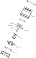
- FIG. 2 is an exploded perspective view of the non-return valve in the preferred embodiment 1 of the present invention.
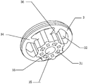
- FIG. 3 is a perspective view of the water-saving core in the preferred embodiment 1 of the present invention.
- FIG. 4 is a cross-sectional view of the valve core in the first position in the preferred embodiment 1 of the present invention.
- Fig. 5 is the sectional view of the valve core in the second position in the preferred embodiment 1 of the present invention.
- FIG. 6 is a perspective view of the valve core in the preferred embodiment 2 of the present invention.
- FIG. 7 is a perspective view of a water-saving core in preferred embodiment 2 of the present invention.
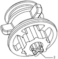
- Fig. 8 is the perspective view of the valve core and the water-saving core after the combination of the preferred embodiment 2 of the present invention.
- FIG. 9 is a cross-sectional view of a valve core and a water-saving core combined in a preferred embodiment 2 of the present invention.
- connection which can be a fixed connection, a detachable connection, or an integral connection, a mechanical connection, an electrical connection, a direct connection, or an indirect connection through an intermediate medium, or an internal connection between two components.
- connection which can be a fixed connection, a detachable connection, or an integral connection, a mechanical connection, an electrical connection, a direct connection, or an indirect connection through an intermediate medium, or an internal connection between two components.
- a water-saving check valve includes: a valve body 1, a valve core 2 and a water-saving core 3;
- the water-saving core 3 is fixedly arranged in the valve body 1, and is provided with a first water outlet channel 31 and a second water outlet channel 32 that are independent of each other; the valve core 2 and the water-saving core 3 are movably cooperated, and are subject to high and low water pressure. The action of moving between the first position and the second position along the axial direction of the valve body 1;
- valve core 2 When the water pressure is high, the valve core 2 is in the first position and closes the first water outlet channel 31; when the water pressure is low, the valve core 2 is in the second position and closes the first water outlet channel 31 31 is open; the second water outlet channel 32 is normally open.
- the valve core 2 and the water-saving core 3 are not in contact, and the first water outlet channel 31 and the second water outlet channel 32 on the water-saving core 3 are both in an open state,
- the bottom of the valve core 2 has lower pressure under the action of the double pressure relief channel of the cavity, and the valve core 2 is easier to open, so that the check valve has a larger flow rate and a lower opening water pressure.
- increasing the water-passing area under the cavity means that the flow rate increases synchronously to meet the low pressure and large flow rate.
- valve body 1 and the water-saving core 3 are in a closed state in contact with the first water outlet channel 31.
- the flow is controlled by the sealing ring 4 and the water-saving core 3, and the constant flow condition is satisfied, and only the second water outlet Channel 32 control, high stability.
- the water-saving core 3 is provided with a channel 33 movably connected to the valve core 2 at the axial center; the water-saving core 3 is provided with the first water outlet channel 31 outside the side wall of the channel 33 . .
- valve core 2 When the valve core 2 moves to the first position, the side of the valve core 2 facing the water saving core 3 abuts the water inlet end of the first water outlet channel 31 , so that the valve core 2 closes the first water outlet channel 31 .
- the second water outlet channel 32 is located outside the side wall of the first water outlet channel 31, so that the second water outlet channel 32 can be kept in a normally open state.
- the valve core 2 in order to realize that the valve core 2 can be automatically reset from the first position to the second position after the water pressure changes from high to low, the valve core 2 also includes a return spring 5.
- the return spring 5 When the valve core 2 is in the first position , the return spring 5 accumulates an elastic return force.
- the water-saving core 3 includes an outer core 34 , an inner core 35 and a plurality of spokes 36 fixedly connected to the outer core 34 and the inner core 35 ; a channel is provided at the axial center of the inner core 35 . 33 , a plurality of first water outlet channels 31 are arranged outside the side wall of the channel 33 ; a second water outlet channel 32 is formed between the outer core body 34 and the inner core body 35 .
- valve core 2 includes a core body 21 and a support body 22 , and the support body 22 has an annular sealing surface 23 .
- valve core 2 moves downward along the axial direction of the valve body 1 to the first position, and the annular sealing surface 23 of the valve core support The water outlet channel 31 is closed;
- valve core 2 moves upward along the axial direction of the valve body 1 to the second position, the annular sealing surface 23 of the valve core support body 22 leaves the water-saving core 3, and the The first water outlet channel 31 is opened;
- the second water outlet channel 32 is in a normally open state.
- Embodiment 1 the difference between this embodiment and Embodiment 1 is that in Embodiment 1, the first water outlet channel 31 is independently provided on the water-saving core 3 , and has nothing to do with the valve core 2 . In this embodiment, however, the water-saving core 3 is only provided with a second water outlet channel 32 and a channel 33 movably connected to the valve core 2 .
- One end of the valve core 2 is inserted into the channel 33 , and the first water outlet channel 31 is formed between the side wall of the inserted portion and the inner wall of the channel 33 .
- the first water outlet channel 31 is formed by the cooperation of the valve core 2 and the water saving core 3 .
- the remaining parts are the same as those in Embodiment 1, and are not repeated here.
- the core body 21 of the valve core 2 is axially provided with a convex rib 24 , and the side wall of the inserted portion and the inner wall of the channel 33 form the first water outlet channel 31 .
- the invention is a water-saving check valve, the valve core and the water-saving core are movably matched, and are moved between the first position and the second position along the axial direction of the valve body under the action of the water pressure; when the water pressure is high When the water pressure is low, the valve core is in the first position and the first water outlet channel is closed; when the water pressure is low, the valve core is in the second position and the first water outlet channel is opened; the second water outlet channel is normally open.
- the water-saving check valve of the invention can meet the requirements of low pressure and large flow, has wide application range, low production cost, simple structure and reliable use.
Landscapes
- Engineering & Computer Science (AREA)
- General Engineering & Computer Science (AREA)
- Mechanical Engineering (AREA)
- Check Valves (AREA)
Abstract
本发明提供了一种节水止逆阀,包括:阀体、阀芯和节水芯;所述节水芯固定设置在阀体内,并且设置有相互独立的第一出水通道和第二出水通道;所述阀芯和节水芯活动配合,并受水压高低的作用沿着阀体的轴向在第一位置和第二位置之间移动;当水压高时,所述阀芯位于第一位置,并将所述第一出水通道关闭;当水压低时,所述阀芯位于第二位置,并将所述第一出水通道打开;所述第二出水通道为常开状态。上述的节水止逆阀,可以满足低压大流量的需求。
Description
本发明涉及一种出水装置的配件,尤其涉及止逆阀。
现在市面上的节水止逆阀,不仅具备阻止水路逆流的功能,同时还具有减少水流量、节约水资源的优点。这种节水止逆阀在使用时,当水压较小时,节水止逆阀的水流量较小;当水压增大时,节水止逆阀的水流量同步增大,即在通常情况下,水的流量与水压成正比。因此,现在市面上的节水止逆阀存在流量不稳定的缺点,不适合在流量要求稳定的场合使用。特别是,在一些低水压的环境下,如楼房的顶层,由于水路中水压较低,此时节水止逆阀的水流量较小,根本无法满足使用需求。
发明内容
本发明所要解决的主要技术问题是提供一种节水止逆阀,满足低压大流量的需求。
为了解决上述的技术问题,本发明提供了一种节水止逆阀,包括:阀体、阀芯和节水芯;
所述节水芯固定设置在阀体内,并且设置有相互独立的第一出水通道和第二出水通道;所述阀芯和节水芯活动配合,并受水压高低的 作用沿着阀体的轴向在第一位置和第二位置之间移动;
当水压高时,所述阀芯位于第一位置,并将所述第一出水通道关闭;当水压低时,所述阀芯位于第二位置,并将所述第一出水通道打开;所述第二出水通道为常开状态。
在一较佳实施例中:所述节水芯在轴心处设置有所述阀芯活动连接的通道;所述节水芯在通道的侧壁外设置有所述第一出水通道。
在一较佳实施例中:当所述阀芯运动第一位置,所述阀芯朝向节水芯的一侧与第一出水通道的进水端抵接。
在一较佳实施例中:所述第二出水通道位于第一出水通道的侧壁外。
在一较佳实施例中:还包括复位弹簧,所述阀芯位于第一位置时,所述复位弹簧积累弹性复位力。
本发明还提供了一种节水止逆阀,包括:阀体、阀芯和节水芯;
所述节水芯固定设置在阀体内,并且设置有第二出水通道;所述阀芯和节水芯活动配合,并受水压高低的作用沿着阀体的轴向在第一位置和第二位置之间移动;所述阀芯的侧壁与节水芯之间形成第一出水通道;
当水压高时,所述阀芯位于第一位置,并将所述第一出水通道关闭;当水压低时,所述阀芯位于第二位置,并将所述第一出水通道打开;所述第二出水通道为常开状态。
在一较佳实施例中:所述节水芯在轴心处设置有所述阀芯活动连接的通道;所述阀芯的一端插入所述通道内,并且插入部分的侧壁与 通道的内壁之间形成所述第一出水通道。
在一较佳实施例中:当所述阀芯运动第一位置,所述阀芯朝向节水芯的一侧与第一出水通道的进水端抵接。
在一较佳实施例中:所述第二出水通道位于通道的侧壁外。
在一较佳实施例中:还包括复位弹簧,所述阀芯位于第一位置时,所述复位弹簧积累弹性复位力。
相较于现有技术,本发明的技术方案具备以下有益效果:
本发明提供了一种节水止逆阀,在水流处于超低压条件下时,阀芯和节水芯没有接触,节水芯上的内外圈过水通道处于敞开状态,阀芯底部在型腔双重泄压通道作用下具有更低的压力,阀芯更容易被打开,使止逆阀具有更大的流量,更低的开启水压。同时增加型腔下过水面积意味着流量的同步增加,满足低压大流量。当水流处于高压状态下时,阀体和节水芯接触第一出水通道处于闭合状态,此时流量由密封圈和节水芯控制,满足恒流条件,只由第二出水通道控制,稳定性高。
本发明提供了一种节水止逆阀,合理运用了用于止逆结构的阀芯运动,实现另一过水通道开闭合,无额外零件,成本低,结构简单,可靠。
图1为本发明优选实施例1中止逆阀的立体图;
图2为本发明优选实施例1中止逆阀的立体分解图;
图3为本发明优选实施例1中节水芯的立体图;
图4为本发明优选实施例1中阀芯在第一位置时的剖视图;
图5为本发明优选实施例1中阀芯在第二位置时的剖视图;
图6为本发明优选实施例2中阀芯的立体图;
图7为本发明优选实施例2中节水芯的立体图;
图8为本发明优选实施例2阀芯和节水芯组合后的立体图;
图9为本发明优选实施例2阀芯和节水芯组合后的剖视图。
具体连接方式
下面将结合本发明实施例中的附图,对本发明实施例中的技术方案进行清楚、完整地描述;显然,所描述的实施例仅仅是本发明一部分实施例,而不是全部的实施例,基于本发明中的实施例,本领域普通技术人员在没有做出创造性劳动前提下所获得的所有其他实施例,都属于本发明保护的范围。
在本发明的描述中,需要说明的是,术语“上”、“下”、“内”、“外”、“顶/底端”等指示的方位或位置关系为基于附图所示的方位或位置关系,仅是为了便于描述本发明和简化描述,而不是指示或暗示所指的装置或元件必须具有特定的方位、以特定的方位构造和操作,因此不能理解为对本发明的限制。此外,术语“第一”、“第二”仅用于描述目的,而不能理解为指示或暗示相对重要性。
在本发明的描述中,需要说明的是,除非另有明确的规定和限定,术语“安装”、“设置有”、“套设/接”、“连接”等,应做广义理解,例 如“连接”,可以是固定连接,也可以是可拆卸连接,或一体地连接,可以是机械连接,也可以是电连接,可以是直接相连,也可以通过中间媒介间接相连,可以是两个元件内部的连通,对于本领域的普通技术人员而言,可以具体情况理解上述术语在本发明中的具体含义。
实施例1
参考图1-图5,一种节水止逆阀,包括:阀体1、阀芯2和节水芯3;
所述节水芯3固定设置在阀体1内,并且设置有相互独立的第一出水通道31和第二出水通道32;所述阀芯2和节水芯3活动配合,并受水压高低的作用沿着阀体1的轴向在第一位置和第二位置之间移动;
当水压高时,所述阀芯2位于第一位置,并将所述第一出水通道31关闭;当水压低时,所述阀芯2位于第二位置,并将所述第一出水通道31打开;所述第二出水通道32为常开状态。
上述的节水止逆阀,在水流处于超低压条件下时,阀芯2和节水芯3没有接触,节水芯3上的第一出水通道31和第二出水通道32都处于敞开状态,阀芯2底部在型腔双重泄压通道作用下具有更低的压力,阀芯2更容易被打开,使止逆阀具有更大的流量,更低的开启水压。同时增加型腔下过水面积意味着流量的同步增加,满足低压大流量。当水流处于高压状态下时,阀体1和节水芯3接触第一出水通道31处于闭合状态,此时流量由密封圈4和节水芯3控制,满足恒流条件,只由第二出水通道32控制,稳定性高。从而实现了合理运用用于 止逆结构的阀芯2运动,实现第一过水通道的开闭合,无额外零件,成本低,结构简单,可靠。
本实施例中,所述节水芯3在轴心处设置有所述阀芯2活动连接的通道33;所述节水芯3在通道33的侧壁外设置有所述第一出水通道31。
当所述阀芯2运动第一位置,所述阀芯2朝向节水芯3的一侧与第一出水通道31的进水端抵接,从而实现阀芯2关闭第一出水通道31。
所述第二出水通道32位于第一出水通道31的侧壁外,这样第二出水通道32就可以保持常开状态。
本实施例中,为了实现阀芯2在水压由高变低后,阀芯2可以自动从第一位置复位到第二位置,还包括复位弹簧5,所述阀芯2位于第一位置时,所述复位弹簧5积累弹性复位力。
本实施例中,所述节水芯3包括一外芯体34、内芯体35和若干固接外芯体34和内芯体35的辐条36;在内芯体35轴心处设置有通道33,在通道33的侧壁外设置有若干条第一出水通道31;外芯体34和内芯体35之间形成第二出水通道32。
本实施例中,所述阀芯2包括芯体21、支撑体22,所述支撑体22具有一环形封堵面23。
使用时,当水压高时,参考图5,所述阀芯2沿着阀体1的轴向向下移动至第一位置,阀芯支撑体22的环形封堵面23将所述第一出水通道31关闭;
当水压低时,参考图4,所述阀芯2沿着阀体1的轴向向上移动至第二位置,阀芯支撑体22的环形封堵面23离开节水芯3,并将所述第一出水通道31打开;
所述第二出水通道32为常开状态。
实施例2
参考图6-图9,本实施例与实施例1的区别在于:实施例1中第一出水通道31是单独设置在节水芯3上的,与阀芯2无关。而本实施例中,节水芯3上只设置有第二出水通道32和与所述阀芯2活动连接的通道33。
所述阀芯2的一端插入所述通道33内,并且插入部分的侧壁与通道33的内壁之间形成所述第一出水通道31。这样就是依靠阀芯2和节水芯3共同配合形成了第一出水通道31。其余部分与实施例1相同,不再赘述。
本实施例中,所述阀芯2的芯体21轴向设有凸棱24,其插入部分的侧壁与通道33的内壁形成第一出水通道31。
以上所述,仅为本发明较佳的具体实施方式,但本发明的设计构思并不局限于此,任何熟悉本技术领域的技术人员在本发明揭露的技术范围内,利用此构思对本发明进行非实质性的改动,均属于侵犯本发明保护范围的行为。
本发明一种节水止逆阀,其阀芯和节水芯活动配合,并受水压高低的作用沿着阀体的轴向在第一位置和第二位置之间移动;当水压高时,阀芯位于第一位置,并将第一出水通道关闭;当水压低时,阀芯位于第二位置,并将第一出水通道打开;第二出水通道为常开状态。本发明节水止逆阀,可以满足低压大流量的需求,适用范围广,且生产成本低,结构简单,使用可靠。
Claims (12)
- 一种节水止逆阀,其特征在于包括:阀体、阀芯和节水芯;所述节水芯固定设置在阀体内,并且设置有相互独立的第一出水通道和第二出水通道;所述阀芯和节水芯活动配合,并受水压高低的作用沿着阀体的轴向在第一位置和第二位置之间移动;当水压高时,所述阀芯位于第一位置,并将所述第一出水通道关闭;当水压低时,所述阀芯位于第二位置,并将所述第一出水通道打开;所述第二出水通道为常开状态。
- 根据权利要求1所述的一种节水止逆阀,其特征在于:所述节水芯在轴心处设置有所述阀芯活动连接的通道;所述节水芯在通道的侧壁外设置有所述第一出水通道。
- 根据权利要求2所述的一种节水止逆阀,其特征在于:当所述阀芯运动第一位置,所述阀芯朝向节水芯的一侧与第一出水通道的进水端抵接。
- 根据权利要求1所述的一种节水止逆阀,其特征在于:所述第二出水通道位于第一出水通道的侧壁外。
- 根据权利要求1所述的一种节水止逆阀,其特征在于:所述阀芯包括芯体、支撑体,所述支撑体具有一环形封堵面;所述节水芯包括外芯体、内芯体和若干固接外芯体和内芯体的辐条;在内芯体轴心处设置有通道,在通道的侧壁外设置有若干条第一出水通道;外芯体和内芯体之间形成第二出水通道。
- 根据权利要求1-6中任一项所述的一种节水止逆阀,其特征在 于:还包括复位弹簧,所述阀芯位于第一位置时,所述复位弹簧积累弹性复位力。
- 一种节水止逆阀,其特征在于包括:阀体、阀芯和节水芯;所述节水芯固定设置在阀体内,并且设置有第二出水通道;所述阀芯和节水芯活动配合,并受水压高低的作用沿着阀体的轴向在第一位置和第二位置之间移动;所述阀芯的侧壁与节水芯之间形成第一出水通道;当水压高时,所述阀芯位于第一位置,并将所述第一出水通道关闭;当水压低时,所述阀芯位于第二位置,并将所述第一出水通道打开;所述第二出水通道为常开状态。
- 根据权利要求7所述的一种节水止逆阀,其特征在于:所述节水芯在轴心处设置有所述阀芯活动连接的通道;所述阀芯的一端插入所述通道内,并且插入部分的侧壁与通道的内壁之间形成所述第一出水通道。
- 根据权利要求8所述的一种节水止逆阀,其特征在于:当所述阀芯运动第一位置,所述阀芯朝向节水芯的一侧与第一出水通道的进水端抵接。
- 根据权利要求7所述的一种节水止逆阀,其特征在于:所述第二出水通道位于通道的侧壁外。
- 根据权利要求7所述的一种节水止逆阀,其特征在于:所述节水芯包括外芯体、内芯体和若干固接外芯体和内芯体的辐条,外芯体和内芯体之间形成第二出水通道;所述阀芯的芯体轴向设有凸棱。
- 根据权利要求7-11中任一项所述的一种节水止逆阀,其特征在于:还包括复位弹簧,所述阀芯位于第一位置时,所述复位弹簧积累弹性复位力。
Applications Claiming Priority (2)
| Application Number | Priority Date | Filing Date | Title |
|---|---|---|---|
| CN202011457119.3 | 2020-12-10 | ||
| CN202011457119.3A CN114623270A (zh) | 2020-12-10 | 2020-12-10 | 一种节水止逆阀 |
Publications (1)
| Publication Number | Publication Date |
|---|---|
| WO2022121990A1 true WO2022121990A1 (zh) | 2022-06-16 |
Family
ID=81896168
Family Applications (1)
| Application Number | Title | Priority Date | Filing Date |
|---|---|---|---|
| PCT/CN2021/136841 Ceased WO2022121990A1 (zh) | 2020-12-10 | 2021-12-09 | 一种节水止逆阀 |
Country Status (2)
| Country | Link |
|---|---|
| CN (1) | CN114623270A (zh) |
| WO (1) | WO2022121990A1 (zh) |
Cited By (3)
| Publication number | Priority date | Publication date | Assignee | Title |
|---|---|---|---|---|
| CN116428378A (zh) * | 2023-04-06 | 2023-07-14 | 宁波方太厨具有限公司 | 旁通阀及包含其的热水器 |
| CN116464826A (zh) * | 2023-03-29 | 2023-07-21 | 宁波方太厨具有限公司 | 旁通阀及包含其的热水器 |
| GB2620618A (en) * | 2022-07-14 | 2024-01-17 | Site And Field Services Ltd | Valve assembly |
Citations (7)
| Publication number | Priority date | Publication date | Assignee | Title |
|---|---|---|---|---|
| JPH0566378U (ja) * | 1992-02-18 | 1993-09-03 | 株式会社イナックス | 定流量弁付き逆止弁 |
| CN201475437U (zh) * | 2009-07-17 | 2010-05-19 | 泉州中宇卫浴科技实业有限公司 | 恒流单向阀 |
| CN203023553U (zh) * | 2012-11-08 | 2013-06-26 | 深圳市大能节能技术有限公司 | 止回式节水阀 |
| CN203516859U (zh) * | 2013-10-25 | 2014-04-02 | 厦门松霖科技有限公司 | 一种节水止逆阀 |
| CN205908830U (zh) * | 2016-07-05 | 2017-01-25 | 厦门松霖科技有限公司 | 止逆阀 |
| CN206175738U (zh) * | 2016-09-21 | 2017-05-17 | 厦门立霖卫浴有限公司 | 节水单向阀结构 |
| CN215487836U (zh) * | 2020-12-10 | 2022-01-11 | 厦门松霖科技股份有限公司 | 节水止逆阀 |
-
2020
- 2020-12-10 CN CN202011457119.3A patent/CN114623270A/zh not_active Withdrawn
-
2021
- 2021-12-09 WO PCT/CN2021/136841 patent/WO2022121990A1/zh not_active Ceased
Patent Citations (7)
| Publication number | Priority date | Publication date | Assignee | Title |
|---|---|---|---|---|
| JPH0566378U (ja) * | 1992-02-18 | 1993-09-03 | 株式会社イナックス | 定流量弁付き逆止弁 |
| CN201475437U (zh) * | 2009-07-17 | 2010-05-19 | 泉州中宇卫浴科技实业有限公司 | 恒流单向阀 |
| CN203023553U (zh) * | 2012-11-08 | 2013-06-26 | 深圳市大能节能技术有限公司 | 止回式节水阀 |
| CN203516859U (zh) * | 2013-10-25 | 2014-04-02 | 厦门松霖科技有限公司 | 一种节水止逆阀 |
| CN205908830U (zh) * | 2016-07-05 | 2017-01-25 | 厦门松霖科技有限公司 | 止逆阀 |
| CN206175738U (zh) * | 2016-09-21 | 2017-05-17 | 厦门立霖卫浴有限公司 | 节水单向阀结构 |
| CN215487836U (zh) * | 2020-12-10 | 2022-01-11 | 厦门松霖科技股份有限公司 | 节水止逆阀 |
Cited By (4)
| Publication number | Priority date | Publication date | Assignee | Title |
|---|---|---|---|---|
| GB2620618A (en) * | 2022-07-14 | 2024-01-17 | Site And Field Services Ltd | Valve assembly |
| GB2620618B (en) * | 2022-07-14 | 2025-05-21 | Site And Field Services Ltd | Valve assembly |
| CN116464826A (zh) * | 2023-03-29 | 2023-07-21 | 宁波方太厨具有限公司 | 旁通阀及包含其的热水器 |
| CN116428378A (zh) * | 2023-04-06 | 2023-07-14 | 宁波方太厨具有限公司 | 旁通阀及包含其的热水器 |
Also Published As
| Publication number | Publication date |
|---|---|
| CN114623270A (zh) | 2022-06-14 |
Similar Documents
| Publication | Publication Date | Title |
|---|---|---|
| WO2022121990A1 (zh) | 一种节水止逆阀 | |
| US20140332097A1 (en) | Flow-volume regulator | |
| US9599243B1 (en) | Inline relief valve with parabolic piston face | |
| US2710023A (en) | Check-unit or valve | |
| US7331359B2 (en) | Valve with bi-loading seal | |
| KR102589725B1 (ko) | 체크밸브 기능을 가지는 초저온밸브 | |
| US6925662B1 (en) | Diverter spout | |
| GB2537209A (en) | A water saving mechanism with high flow volume in low pressure | |
| CN217898938U (zh) | 防冻阀 | |
| CN103711964B (zh) | 自对准阀塞 | |
| CN116006742A (zh) | 单向稳流阀及热水器 | |
| CN209058808U (zh) | 烹饪器具 | |
| JP3373338B2 (ja) | 逆止め弁付ボールバルブ | |
| KR102376051B1 (ko) | 스로틀 장치 및 이를 구비한 열교환시스템 | |
| CN205715869U (zh) | 一种稳压阀 | |
| CN215487836U (zh) | 节水止逆阀 | |
| CN219013457U (zh) | 管件连接结构及其应用的灌溉定时阀 | |
| CN220060650U (zh) | 一种单向阀 | |
| CN212536788U (zh) | 限流单向阀 | |
| CN213332552U (zh) | 一种简易轴流式单向阀 | |
| CN210398103U (zh) | 一种防水锤组件和具有该组件的出水装置 | |
| CN109098261B (zh) | 一种侧滑磁吸式防臭排水阀芯及排水设备 | |
| CN217736305U (zh) | 进气阀 | |
| EP3690293B1 (en) | Block and fluid control device | |
| CN223985406U (zh) | 电子膨胀阀 |
Legal Events
| Date | Code | Title | Description |
|---|---|---|---|
| 121 | Ep: the epo has been informed by wipo that ep was designated in this application |
Ref document number: 21902695 Country of ref document: EP Kind code of ref document: A1 |
|
| NENP | Non-entry into the national phase |
Ref country code: DE |
|
| 122 | Ep: pct application non-entry in european phase |
Ref document number: 21902695 Country of ref document: EP Kind code of ref document: A1 |