WO2022118683A1 - 小動物の生体情報取得方法、生体情報取得プログラム、及び生体情報取得装置 - Google Patents
小動物の生体情報取得方法、生体情報取得プログラム、及び生体情報取得装置 Download PDFInfo
- Publication number
- WO2022118683A1 WO2022118683A1 PCT/JP2021/042616 JP2021042616W WO2022118683A1 WO 2022118683 A1 WO2022118683 A1 WO 2022118683A1 JP 2021042616 W JP2021042616 W JP 2021042616W WO 2022118683 A1 WO2022118683 A1 WO 2022118683A1
- Authority
- WO
- WIPO (PCT)
- Prior art keywords
- mouse
- biological information
- information
- small animal
- cage
- Prior art date
- Legal status (The legal status is an assumption and is not a legal conclusion. Google has not performed a legal analysis and makes no representation as to the accuracy of the status listed.)
- Ceased
Links
Images




Classifications
-
- A—HUMAN NECESSITIES
- A01—AGRICULTURE; FORESTRY; ANIMAL HUSBANDRY; HUNTING; TRAPPING; FISHING
- A01K—ANIMAL HUSBANDRY; AVICULTURE; APICULTURE; PISCICULTURE; FISHING; REARING OR BREEDING ANIMALS, NOT OTHERWISE PROVIDED FOR; NEW BREEDS OF ANIMALS
- A01K29/00—Other apparatus for animal husbandry
-
- A—HUMAN NECESSITIES
- A01—AGRICULTURE; FORESTRY; ANIMAL HUSBANDRY; HUNTING; TRAPPING; FISHING
- A01K—ANIMAL HUSBANDRY; AVICULTURE; APICULTURE; PISCICULTURE; FISHING; REARING OR BREEDING ANIMALS, NOT OTHERWISE PROVIDED FOR; NEW BREEDS OF ANIMALS
- A01K29/00—Other apparatus for animal husbandry
- A01K29/005—Monitoring or measuring activity
-
- G—PHYSICS
- G06—COMPUTING OR CALCULATING; COUNTING
- G06V—IMAGE OR VIDEO RECOGNITION OR UNDERSTANDING
- G06V10/00—Arrangements for image or video recognition or understanding
- G06V10/10—Image acquisition
- G06V10/12—Details of acquisition arrangements; Constructional details thereof
- G06V10/14—Optical characteristics of the device performing the acquisition or on the illumination arrangements
-
- G—PHYSICS
- G06—COMPUTING OR CALCULATING; COUNTING
- G06V—IMAGE OR VIDEO RECOGNITION OR UNDERSTANDING
- G06V40/00—Recognition of biometric, human-related or animal-related patterns in image or video data
- G06V40/10—Human or animal bodies, e.g. vehicle occupants or pedestrians; Body parts, e.g. hands
Definitions
- the present invention relates to a biological information acquisition method for acquiring biological information of a small animal such as a mouse, a biological information acquisition program, and a biological information acquisition device.
- Non-Patent Document 1 There is also a method of anesthetizing a mouse to acquire biological information of a mouse under anesthesia (for example, see Non-Patent Document 1), and a method of acquiring biological information of a mouse from the tail portion of the mouse (for example, non-patent document 1). See Patent Document 2).
- the mouse may be physically affected by the anesthetic.
- the biological information is acquired from the tail portion in a state where the mouse is placed in a bag and the behavior of the mouse is restricted (restrained). Therefore, the mouse feels stress due to the restricted behavior, and the value is different from that in the state where the behavior is not restricted. As a result, it may not be possible to acquire biological information when the mouse is not feeling stress.
- the mouse can move freely in the cage. Therefore, depending on the movement of the mouse, for example, when the mouse stands up, the exposed skin portion of the back cannot be photographed by the camera, and there is a possibility that the biological information of the mouse cannot be acquired.
- the present invention has been made to solve the above problems, and is a biological information acquisition method, a biological information acquisition program, which acquires biological information without giving stress to small animals without being affected by the movement of small animals. And to provide a biometric information acquisition device.
- the present invention includes a step of acquiring image information of a hand and / or a foot of a small animal walking on four legs, a step of extracting predetermined signal information from the acquired image information, and the extracted predetermined signal information. It has a step of acquiring biological information of the small animal by processing.
- the present invention includes a step of acquiring image information of a hand and / or a foot of a small animal walking on four legs, a step of extracting predetermined signal information from the acquired image information, and the extracted predetermined signal information.
- the computer is made to execute the step of acquiring the biological information of the small animal by processing.
- the present invention has extracted an image information acquisition unit that acquires image information of the hand and / or foot of a small animal that walks on four legs, and a signal information extraction unit that extracts predetermined signal information from the acquired image information. It includes a biological information acquisition unit that acquires biological information of the small animal by processing the predetermined signal information.
- the present invention it is possible to acquire the biological information of a small animal without being affected by the movement of the small animal and without giving stress to the small animal.
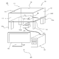
- the biological information acquisition device 1 includes a storage unit 10, an image information acquisition unit 20, a lighting unit 30, and an information processing unit 40.
- the accommodating portion 10 is for accommodating a small animal for acquiring biological information, and is composed of a cage 10.
- a small animal such as a rat or a mouse M is placed in the cage 10.
- the case of acquiring the biological information of the mouse M will be described as an example.
- the upper surface portion 11 of the cage 10 is opened to form a substantially rectangular parallelepiped shape, and the mouse M is moved in and out of the cage 10 from the opened upper surface portion 11 side. Further, in the cage 10, each of the four side surface portions 12, 13, 14, 15 and the bottom surface portion 16 is composed of a transparent glass plate. As a result, the mouse M inside the cage 10 can be visually recognized even from the outside of the side surface of the cage 10 and the outside of the bottom surface of the cage 10.
- Legs 16a, 16b, 16c, 16d for supporting the cage 10 are provided at each of the four corners of the bottom surface portion 16 of the cage 10.
- the legs 16a, 16b, 16c, 16d are formed in the shape of a rectangular parallelepiped and extend in a direction facing the bottom surface 16 (downward of the cage 10).
- the presence of the legs 16a, 16b, 16c, 16d causes the cage 10 to be positioned at a predetermined height. As a result, a predetermined distance is formed between the bottom surface portion 16 of the cage 10 and the mounting surface of the mounting table on which the cage 10 is placed, although not shown.
- the image information acquisition unit 20 acquires an image of the mouse M and is composed of an RGB camera 20.
- the RGB camera 20 is provided with a plurality of detection elements having sensitivity to the light intensity in the wavelength region corresponding to each color of R (red), G (green), and B (blue), and can acquire image information. It can be done.
- the RGB camera 20 is arranged between the bottom surface portion 16 of the cage 10 and the mounting surface on which the cage 10 is placed. That is, it is arranged on the lower side of the bottom surface portion 16 of the cage 10. Further, in order to photograph the abdominal side of the mouse M in the cage 10, the RGB camera 20 is arranged in a state where the lens portion 20a of the camera faces the bottom surface portion 16 side of the cage 10.
- the lighting unit 30 is for illuminating the mouse M in the cage 10, and is composed of an LED light.
- the LED light 30 is located between the bottom surface portion 16 of the cage 10 and the mounting surface on which the cage 10 is placed, and is arranged on the left and right sides of the RGB camera 20.
- the LED light 30 illuminates the mouse M in the cage 10 from the bottom surface 16 side of the cage 10.
- the lighting unit 30 is composed of an LED light, but the mouse M may be illuminated by an infrared lamp. Since the mouse M reacts to visible light, it is preferable to illuminate the mouse M with an infrared lamp when it is desired to avoid the influence of the visible light on the mouse M.
- the information processing unit 40 is for processing image information of the mouse M captured by the RGB camera 20, and is composed of a personal computer (hereinafter, simply referred to as a personal computer) 40.
- the personal computer 40 includes a server device 41 that processes and stores various information, and a display 42 as a display device that displays various images.
- the RGB camera 20 and the display 42 are connected to the server device 41. Then, image information is input to the server device 41 from the RGB camera 20. Further, although not shown, various devices such as a keyboard and a printer are connected to the server device 41 in addition to the RGB camera 20 and the display 42.
- the server device 41 includes a control unit 410, a storage unit 420, a communication unit 430, a power supply unit 440, and the like.
- the control unit 410 controls the overall operation of the biometric information acquisition device 1, such as the operation of the server device 41, the operation of the RGB camera 20 connected to the server device 41, and the control of the operation of the display 42.
- the control unit 410 includes a CPU (Central Processing Unit) which is a processor, a ROM (Read Only Memory) and a RAM (Random Access Memory) which are memories, and the like.
- CPU Central Processing Unit
- ROM Read Only Memory
- RAM Random Access Memory
- the storage unit 420 is composed of, for example, SSD (Solid State Drive) or HDD (Hard Disk Drive) which is a semiconductor memory, and stores information acquired by the control unit 410.
- SSD Solid State Drive
- HDD Hard Disk Drive
- the communication unit 430 communicates with an external device via a network such as another server device.
- the power supply unit 440 supplies power to each part constituting the server device 41 according to a state such as a power on state or a power off state according to an instruction from the control unit 410.
- the control unit 410, the storage unit 420, and the communication unit 430 are connected by an internal bus, although not shown.
- the server device 41 is also provided with a connection unit for connecting an external information storage medium such as a USB memory.
- the control unit 410 loads the information processing program stored in the ROM into the RAM and executes it, so that the image information reading unit 411, the image information specifying unit 412, and the signal information extracting unit are executed. It functions as a signal information smoothing unit 414, a signal information filter unit 415, a signal information peak detection unit 416, a biological information calculation unit 417, and the like.
- the image information reading unit 411 causes the RGB camera 20 connected to the server device 41 to perform shooting, and also performs a process of reading (acquiring) the image (moving image) acquired by the RGB camera 20 into the control unit 410. Is.
- the image information specifying unit 412 performs a process of specifying the image information for which the signal is extracted by the signal information extracting unit 413 among the image information read by the control unit 410.
- the image information specifying unit 412 automatically identifies a moving image taken by the RGB camera 20 in a stationary state in which the mouse M does not move for a certain period of time. Further, the image information specifying unit 412 automatically identifies the image of the foot (sole) L of the mouse from the image on the abdomen side of the mouse M.
- the image information specifying unit 412 automatically identifies the image in the stationary state or the image of the foot portion L of the mouse M, but the present invention is not limited to this.
- the image may be specified based on an operation signal from a keyboard or the like. That is, those images may be manually specified.
- the signal information extraction unit 413 performs a process of extracting a G signal, which is a predetermined signal of the present invention, from the RGB signals in the image of the foot portion L of the mouse M specified by the image information identification unit 412. .
- the G signal means a green component image signal
- an R signal means a red component image signal
- a B signal means a blue component image signal.
- the signal information smoothing unit 414 performs processing for removing unnecessary signals, so-called noise, included in the signal information.
- the signal information filter unit 415 performs a process of extracting a signal of a specific frequency.
- the signal information filter unit 415 performs signal extraction processing by using a bandpass filter program stored in the memory.
- the signal information peak detection unit 416 performs a process of detecting a peak of a signal that changes periodically.
- the biological information calculation unit 417 performs a process of calculating various biological information of the mouse M from the interval between the peaks of the signal detected by the signal information peak detection unit 416.
- the signal information smoothing unit 414, the signal information filter unit 415, the signal information peak detection unit 416, and the biometric information calculation unit 417 constitute the biometric information acquisition unit of the present invention.
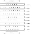
- the mouse M in the cage 10 is photographed by the RGB camera 20 (STEP 10, hereinafter simply referred to as SOO).
- the RGB camera 20 is arranged below the bottom surface portion 16 of the cage 10, and the lens portion 20a thereof faces the bottom surface portion 16 of the cage 10. Therefore, the image taken by the RGB camera 20 is taken from the lower side of the mouse M, and the abdominal side of the mouse M is taken.
- the image information of the mouse M taken by the RGB camera 20 is mainly an image (moving image) showing the abdomen of the mouse M. Further, the image showing the abdomen of the mouse M also includes an image of the foot L of the mouse M, and the image of the foot L is the sole of the foot of the mouse M in contact with the bottom surface 16 of the cage 10. (See FIG. 5).
- the frame rate (fps) of the RGB camera 20 when shooting the mouse M is, for example, about 250 fps, and the frame rate (about 60 fps) when shooting a person. Make it larger than.
- the image information is sent from the RGB camera 20 to the server device 41.
- the image information of the mouse M sent to the server device 41 is read (stored) in the memory of the control unit 410 by the reading process by the image information reading unit 411 (S20).
- the image information specifying unit 412 When the image information of the mouse M is read into the server device 41, the image information specifying unit 412 identifies a moving image in which the mouse M is in a stationary state for a certain period from the read moving image. Further, the image information specifying unit 412 specifies the sole portion of the foot, which is the foot portion L of the mouse M, from the specified moving image. Further, as shown in FIG. 5, the image information specifying unit 412 also specifies an image region R from which a signal is extracted from the identified images of the sole of the foot (S30).
- the signal information extraction unit 413 extracts the G signal from the image area (S40). Specifically, each signal component obtained from the image region R by performing a fast Fourier transform (Fast Fourier Transform) process or a wavelet transform (Wavelet Transform) process is confirmed.
- a fast Fourier transform Fast Fourier Transform
- Wavelet Transform wavelet transform
- the signal information smoothing unit 414 performs the G signal smoothing process by removing unnecessary signal information from the extracted (confirmed) G signal (S50).
- the signal information filter unit 415 performs a bandpass filter process for extracting a signal having a specific frequency from the smoothed G signal (S60). Specifically, in the process, each of the respiratory signal and the heartbeat signal of the mouse M is extracted.
- the signal information peak detection unit 416 detects the peaks of the respiratory signal and the heartbeat signal that change periodically (S70).
- the biological information calculation unit 417 calculates the respiratory rate and the heart rate of the mouse M from the number of peaks per unit time. Further, the biological information calculation unit 417 is adapted to calculate various biological information such as respiratory variability and heart rate variability of the mouse M from the interval between peaks (S80).
- Various biological information of the mouse M such as the detected respiratory rate and heart rate is stored in the memory and displayed on the display 42 or the like.
- biological information such as the respiratory rate and heart rate of the mouse M was calculated from the image of the foot L of the mouse M.
- the body of the mouse M is not incised.
- biological information such as the respiratory rate and heart rate of the mouse M can be calculated without giving a physical burden or stress to the mouse M.
- the abdominal side of mouse M was taken.
- the foot portion L of the mouse M can be photographed together with the image of the abdomen side of the mouse M.
- the image of the foot L necessary for calculating the respiratory rate, the heart rate, and the like of the mouse M can be acquired.
- the RGB camera 20 is arranged below the bottom surface 16 of the cage 10 made of a transparent glass plate, and the mouse M is photographed from below the position of the mouse M in the cage 10. ..
- the hand (palm) and foot (sole) L of the mouse M in contact with the bottom surface 16 of the cage 10 can be photographed by the RGB camera 20, and the image of the foot L can be taken.
- the respiratory rate and heart rate of the mouse M can be calculated.
- the respiratory rate, heart rate, etc. can be calculated without restricting the movement of the mouse M, such as fixing the mouse M in order to photograph the foot L, so that the natural state can be obtained without giving stress.
- the biological information of a certain mouse M can be calculated.
- the foot portion L of the mouse M is always in contact with the bottom surface portion 16. Therefore, for example, even if the mouse M stands up, the respiratory rate and the heart rate of the mouse M can be calculated from the image of the foot portion L in contact with the bottom surface portion 16. Thereby, the biological information of the mouse M can be calculated without being affected by the movement of the mouse M in the cage 10.
- the RGB camera 20 is used to photograph the foot L of the mouse M, but the present invention is not limited to this. Any image can be taken as long as it can extract a signal that can detect the pulse wave of the mouse.
- the foot portion L of the mouse M may be photographed with an infrared camera, and the respiratory rate, heart rate, etc. of the mouse M may be calculated from the infrared rays.
- the mouse M reacts to visible light, it is effective when it is desired to suppress the influence of light on the mouse M.
- the biological information of the mouse M is calculated based on the G signal extracted from the image information, but the present invention is not limited to this.
- the biological information of the mouse M may be calculated based on the R signal or the B signal, or the biological information of the mouse M may be calculated by combining the R signal, the G signal, and the B signal. May be good.
- the respiratory rate and heart rate of the mouse M are calculated from the G signal, but the present invention is not limited to this.
- various biological information of mouse M such as blood pressure, oxygen saturation in blood, and pyrylrubin value can be calculated from RGB signals and infrared rays.
- the foot portion L of the mouse M is specified from the image taken by the RGB camera 20, and the respiratory rate, heart rate, etc. of the mouse M are calculated from the image of the foot portion L.
- the hand part (palm) of the mouse M may be specified from the image, and biological information such as the respiratory rate and the heart rate of the mouse M may be calculated from the hand part, the foot part L, or both of them. That is, the image may be any part as long as it is the hand part or the foot part L of the mouse M.
- the foot portion L of the mouse M is photographed by the RGB camera 20 connected to the server device 41, and the respiratory rate and the heart rate of the mouse M are calculated from the image acquired by the photographing.
- the image information of the foot L of the mouse taken by a camera other than the biological information acquisition device 1 is taken into the server device 41 via the Internet or a USB memory, and the image information taken in is the breathing rate and heart rate of the mouse M. You may try to calculate biometric information such as.
- the abdominal side of the mouse M is photographed from the underside of the mouse M in the cage 10.
- a reflector such as a mirror is arranged under the bottom surface portion 16 of the cage 10.
- the RGB camera 20 may take an image of the abdominal side portion including the hand portion and the foot portion L of the mouse M reflected in the mirror from the upper side of the cage 10 (from above the mouse M).
- the mouse M has been described as an example of a small animal for acquiring biological information, but the present invention is not limited to this.
- it may be an animal such as a dog or a cat. That is, any skin portion such as the palm or sole of the foot may be in contact with the bottom surface portion 16 when placed in the cage 10.
- the present invention is not limited to the above-described embodiment of the present invention, but also includes modifications within the range in which the object of the present invention can be achieved.
- a modified example of the present embodiment will be described.
- the modifications described below will be described only with respect to the differences from the present embodiment already described, and the same components will be designated by the same reference numerals and the description thereof will be omitted.
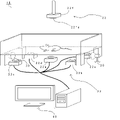
- the image information acquisition unit 21 of the biological information acquisition device 1A according to the present modification 1 is composed of a plurality of RGB cameras, and the present modification 1 has five RGB cameras 21a, 21b, as shown in FIG. It is composed of 21c, 21d, and 21e.
- the RGB cameras 21a, 21b, 21c, 21d, and 21e are arranged near the four corners and the center of the bottom surface portion 16 so that the entire bottom surface portion 16 of the cage 10 can be photographed.
- control unit 410 also functions as a mouse position specifying unit 418.
- the mouse position specifying unit 418 performs a process of specifying the position of the mouse M in the cage 10 from the images of the RGB cameras 21a, 21b, 21c, 21d, 21e.
- the location of the mouse M in the cage 10 is specified from the image information. (S21). Then, after the position of the mouse M is specified, the biological information of the mouse M is acquired (S30 to S80).
- the position of the mouse M in the cage 10 can be specified by photographing the mouse M with a plurality of RGB cameras 21a, 21b, 21c, 21d, 21e. Thereby, the behavior of the mouse M in the cage 10 can be observed. Further, since the respiratory rate, the heart rate, and the like can be calculated according to the position of the mouse M in the cage 10, it is possible to acquire the biological information according to the behavior of the mouse M.
- RGB cameras 21a, 21b, 21c, 21d, 21e are arranged on the lower side of the bottom surface portion 16 of the cage 10, but the present invention is not limited to this.
- three RGB cameras may be arranged, or eight RGB cameras may be arranged. That is, it suffices if a plurality of RGB cameras can project the entire bottom surface portion 16 in the cage 10, and the location and the number of cameras to be arranged can be freely set.
- the image information acquisition unit 22 of the biological information acquisition device 1B according to the second modification is composed of a plurality of RGB cameras.
- the five RGB cameras 22a and 22b, respectively, are located near the four corners and the center of the bottom surface 16 so that the entire bottom surface 16 of the cage 10 can be photographed in the same manner as the above-mentioned modification 1.
- 22c, 22d, 22e are arranged.
- the image information acquisition unit 22 has an RGB camera 22f arranged on the upper side of the cage 10.
- the RGB camera 22f arranged on the upper side of the cage 10 is arranged in a state where the lens portion 22fa faces the cage 10 side in order to photograph the mouse M in the cage 10.
- the mouse in the cage 10 is photographed from above with the RGB camera 22f. That is, in the second modification, the mouse M in the cage 10 is photographed from above and below.
- the respiratory rate, the heart rate, and the like are calculated from the images of the foot portion L of the mouse M taken by the RGB cameras 22a, 22b, 22c, 22d, 22e arranged under the cage 10. .
- the locus of the behavior of the mouse M in the cage 10 is specified from the image of the mouse M taken by the RGB camera 22f arranged on the upper side of the cage 10. Then, the momentum of the mouse M in the cage 10 is calculated from the locus.
- the respiratory rate and heart rate of the mouse M are calculated from the images taken by the RGB cameras 22a, 22b, 22c, 22d, 22e arranged on the lower side of the cage 10, and the upper side of the cage 10 is calculated.
- the amount of movement of the mouse M is calculated from the image taken by the arranged RGB camera 22f.
- one RGB camera 22f is arranged on the upper side of the cage 10, but the present invention is not limited to this.
- four RGB cameras may be arranged. That is, it suffices if the locus of the behavior of the mouse M in the cage 10 can be specified, and the place to be arranged and the number of cameras can be freely set.
- the bottom surface portion (bottom plate of the cage 10) 16 of the cage 10 is made of an acrylic plate. Further, as shown in FIG. 10, an LED lamp 160 is provided on one end side of a side surface portion of the bottom surface portion 16 made of the acrylic plate.
- the LED lamp 160 is provided so that its light emitting portion faces (contacts) the side surface portion of the bottom surface portion 16, and the LED lamp 160 is provided inside the bottom surface portion 16 from the side surface portion side of the bottom surface portion 16. It is designed to illuminate. As a result, the light of the LED lamp 160 enters only the inside of the acrylic plate which is the bottom surface portion 16.
- the LED lamp 160 is provided to allow light to enter only inside the acrylic plate. By allowing the light of the LED lamp 160 to enter only into the acrylic plate in this way, only the contact portion in contact with the surface portion of the bottom surface portion 16 emits light, and the other non-contact portions do not emit light.
- the mouse M is inserted into the cage 10 in a state where the light is received from the LED lamp 160 in the bottom surface portion (acrylic plate) 16. Then, on the surface portion of the bottom surface portion 16, the portion in contact with the mouse M emits light, and the other portions do not emit light.
- the foot portion L of the mouse M in the cage 10 is in contact with the surface portion of the bottom surface portion 16. Then, as for the contact portion of the foot portion L (for example, the sole portion of the foot), as shown in FIG. 11, the light of the LED lamp 160 emits light only to the portion in contact with the bottom surface portion 16 (by the LED lamp 160). It is illuminated).
- the LED lamp 160 is made to emit light, and the light of the LED lamp 160 is made to enter only into the acrylic plate constituting the bottom surface portion 16, so that when the mouse M is put into the cage 10, for example, the foot Light can be applied (lighted) to a portion in contact with the bottom surface portion 16 of the mouse M, such as the back surface. As a result, light enters the skin portion of the mouse M in contact with the bottom surface portion 16, so that it becomes easy to acquire biological information such as a pulse wave of the mouse M.
- the mouse M in the cage 10 is exposed to light only at the portion in contact with the bottom surface portion 16 and is not exposed to light at the other portions, for example, the eyes of the mouse M are not exposed to light. As a result, it is possible to suppress the influence of the light from the LED lamp 160 on the mouse M. As a result, it becomes possible to suppress the influence of light and acquire more accurate biological information of the mouse M.
- the LED lamp 160 is provided at one end of the side surface portion of the bottom surface portion 16, but the present invention is not limited to this.
- the LED lamp 160 may be provided on both ends of the side surface portion of the bottom surface portion 16 or on all the side surface portions of the bottom surface portion 16. That is, any one may be used as long as it can allow light to enter only in the acrylic plate which is the bottom surface portion 16.
- the bottom surface portion 16 is made of an acrylic plate, but the present invention is not limited to this.
- it may be composed of polycarbonate, urethane, glass, or the like. That is, if the light of the LED lamp 160 is put into the bottom surface portion 16 and the contact portion such as the foot portion L emits light when the foot portion L or the hand portion of the mouse M comes into contact with the bottom surface portion 16. It may be any of them.
- a system S for acquiring the biological information of the mouse M may be constructed by connecting a plurality of biological information acquisition devices 1 in different areas or places via the Internet.
- M small animal (mouse) 1 Biometric information acquisition device 20 Image information acquisition unit (RGB camera) 413 Signal information extraction unit 414 Biometric information acquisition unit (Signal information smoothing unit) 415 Biometric information acquisition unit (signal information filter unit) 416 Biometric information acquisition unit (signal information peak detection unit) 417 Biometric information acquisition unit (Biological information calculation unit)
Landscapes
- Life Sciences & Earth Sciences (AREA)
- Engineering & Computer Science (AREA)
- Environmental Sciences (AREA)
- Animal Husbandry (AREA)
- Biodiversity & Conservation Biology (AREA)
- Physics & Mathematics (AREA)
- General Physics & Mathematics (AREA)
- Multimedia (AREA)
- Theoretical Computer Science (AREA)
- Biophysics (AREA)
- Human Computer Interaction (AREA)
- Measurement Of The Respiration, Hearing Ability, Form, And Blood Characteristics Of Living Organisms (AREA)
Priority Applications (2)
| Application Number | Priority Date | Filing Date | Title |
|---|---|---|---|
| US17/777,895 US12190624B2 (en) | 2020-12-03 | 2021-11-19 | Method of acquiring biometric information on small animals, biometric information acquisition program, and biometric information acquisition device |
| JP2022524076A JP7313747B2 (ja) | 2020-12-03 | 2021-11-19 | 小動物の生体情報取得方法、生体情報取得プログラム、及び生体情報取得装置 |
Applications Claiming Priority (4)
| Application Number | Priority Date | Filing Date | Title |
|---|---|---|---|
| JP2020-201373 | 2020-12-03 | ||
| JP2020201373 | 2020-12-03 | ||
| JP2021-035903 | 2021-03-07 | ||
| JP2021035903 | 2021-03-07 |
Publications (1)
| Publication Number | Publication Date |
|---|---|
| WO2022118683A1 true WO2022118683A1 (ja) | 2022-06-09 |
Family
ID=81853624
Family Applications (1)
| Application Number | Title | Priority Date | Filing Date |
|---|---|---|---|
| PCT/JP2021/042616 Ceased WO2022118683A1 (ja) | 2020-12-03 | 2021-11-19 | 小動物の生体情報取得方法、生体情報取得プログラム、及び生体情報取得装置 |
Country Status (3)
| Country | Link |
|---|---|
| US (1) | US12190624B2 (https=) |
| JP (1) | JP7313747B2 (https=) |
| WO (1) | WO2022118683A1 (https=) |
Citations (3)
| Publication number | Priority date | Publication date | Assignee | Title |
|---|---|---|---|---|
| US20130096439A1 (en) * | 2011-10-14 | 2013-04-18 | Industrial Technology Research Institute | Method and system for contact-free heart rate measurement |
| JP2018064497A (ja) * | 2016-10-19 | 2018-04-26 | 三菱電機株式会社 | 肉球動物のストレス検知装置 |
| WO2019107246A1 (ja) * | 2017-11-30 | 2019-06-06 | 国立大学法人東北大学 | 生体情報計測装置、生体情報計測プログラム、及び生体情報計測方法 |
Family Cites Families (14)
| Publication number | Priority date | Publication date | Assignee | Title |
|---|---|---|---|---|
| JP3755005B1 (ja) | 2005-08-19 | 2006-03-15 | 国立大学法人室蘭工業大学 | 自律神経活動評価装置 |
| US20080047043A1 (en) * | 2006-08-23 | 2008-02-28 | Carmen Flores-Garvey | Baby crawling pants |
| US7987518B2 (en) * | 2008-12-18 | 2011-08-02 | Betty Calderwood | Child knee pad |
| US9443166B2 (en) * | 2013-09-17 | 2016-09-13 | William Brian Kinard | Animal / pet identification system and method based on biometrics |
| EP2974624A1 (en) * | 2014-07-17 | 2016-01-20 | Universite Paris Descartes | Device for assisting the crawling of an infant |
| CN107239725B (zh) * | 2016-03-29 | 2020-10-16 | 阿里巴巴集团控股有限公司 | 一种信息展示方法、装置及系统 |
| WO2017179846A1 (ko) * | 2016-04-15 | 2017-10-19 | 주식회사 올아이티탑 | 지문과 지정맥을 동시에 인증하는 다면 입체 촬영장치 |
| US20200352136A1 (en) * | 2016-04-30 | 2020-11-12 | Kevin Hanson | Methods and system for pet enrichment |
| JP2019092532A (ja) | 2017-11-17 | 2019-06-20 | 学校法人早稲田大学 | 生体埋め込み型の無線給電型発光システム |
| US11019250B2 (en) * | 2018-03-20 | 2021-05-25 | Iscilab Corporation | Method for implementing animal nose pattern biometric identification system on mobile devices |
| US11715308B2 (en) * | 2018-10-10 | 2023-08-01 | Delaval Holding Ab | Animal identification using vision techniques |
| US12374080B2 (en) * | 2019-08-16 | 2025-07-29 | Stephanie Sujin CHOI | Method for clustering and identifying animals based on the shapes, relative positions and other features of body parts |
| CN114554968B (zh) * | 2019-10-17 | 2024-08-13 | 韦拉索恩股份有限公司 | 用于超声扫描的系统及方法 |
| US11341348B2 (en) * | 2020-03-23 | 2022-05-24 | Alitheon, Inc. | Hand biometrics system and method using digital fingerprints |
-
2021
- 2021-11-19 US US17/777,895 patent/US12190624B2/en active Active
- 2021-11-19 WO PCT/JP2021/042616 patent/WO2022118683A1/ja not_active Ceased
- 2021-11-19 JP JP2022524076A patent/JP7313747B2/ja active Active
Patent Citations (3)
| Publication number | Priority date | Publication date | Assignee | Title |
|---|---|---|---|---|
| US20130096439A1 (en) * | 2011-10-14 | 2013-04-18 | Industrial Technology Research Institute | Method and system for contact-free heart rate measurement |
| JP2018064497A (ja) * | 2016-10-19 | 2018-04-26 | 三菱電機株式会社 | 肉球動物のストレス検知装置 |
| WO2019107246A1 (ja) * | 2017-11-30 | 2019-06-06 | 国立大学法人東北大学 | 生体情報計測装置、生体情報計測プログラム、及び生体情報計測方法 |
Non-Patent Citations (2)
| Title |
|---|
| NAGATA, HISASHI; TANAKA, TAKAHISA; MINAMI, MASAKI; HONDA, SHINKURO: "Pulse wave estimation technology by non-contact sensing", IEICE TECHNICAL REPORT, vol. 119, no. 391 (MICT2019-4), 18 January 2020 (2020-01-18), pages 35 - 40, XP009537205 * |
| TSUMURA, NORIMICHI: "Emotion Monitoring Based on Non-Contact Measurement of Bio-Information Using Cameras", ANNALS OF CHIBA UNIVERSITY VENTURE BUSINESS LABORATORY, no. 19, 1 January 2018 (2018-01-01), pages 7 - 10, XP009537206 * |
Also Published As
| Publication number | Publication date |
|---|---|
| JP7313747B2 (ja) | 2023-07-25 |
| US20230245488A1 (en) | 2023-08-03 |
| JPWO2022118683A1 (https=) | 2022-06-09 |
| US12190624B2 (en) | 2025-01-07 |
Similar Documents
| Publication | Publication Date | Title |
|---|---|---|
| US8698888B2 (en) | Systems and methods for comprehensive human movement analysis | |
| RU2656760C2 (ru) | Система и способ для извлечения физиологической информации из удаленно обнаруженного электромагнитного излучения | |
| RU2697291C2 (ru) | Система и способ определения информации об основных показателях состояния организма | |
| Moco et al. | Ballistocardiographic artifacts in PPG imaging | |
| EP2748743B1 (en) | Data administration system and method | |
| US10242278B2 (en) | Device and method for skin detection | |
| EP3813653B1 (en) | Mobile device applications to measure blood pressure | |
| US20160206216A1 (en) | Device, system and method for skin detection | |
| KR101927287B1 (ko) | 손등, 손톱, 발 피부진단 및 건강 측정장치 | |
| US20240398293A1 (en) | Method and Apparatus for Non-Invasive Hemoglobin Level Prediction | |
| KR20120017948A (ko) | 모션캡쳐 기반의 자세분석을 통한 재활 장치 및 이에 따른 재활 방법 | |
| AU2013260160A1 (en) | System and apparatus for automated total body imaging | |
| Pirzada et al. | Remote photoplethysmography (rPPG): A state-of-the-art review | |
| van Gastel et al. | Near-continuous non-contact cardiac pulse monitoring in a neonatal intensive care unit in near darkness | |
| Pereira et al. | Perspective review of optical imaging in welfare assessment in animal-based research | |
| US11810325B2 (en) | Method, device and system for enabling to analyze a property of a vital sign detector | |
| JP7313747B2 (ja) | 小動物の生体情報取得方法、生体情報取得プログラム、及び生体情報取得装置 | |
| JPWO2022118683A5 (https=) | ||
| Takahashi et al. | Non-contact measurement of pulse wave in rats using an RGB camera | |
| US20240341674A1 (en) | Diabetic foot examination device | |
| JP7253298B2 (ja) | 生体情報取得装置 | |
| JP7314893B2 (ja) | 電子装置、電子装置の制御プログラム及び電子装置の制御方法 | |
| JP6943319B2 (ja) | 判定システム | |
| JP2025056837A (ja) | 小動物の生体情報計測装置及び生体情報計測方法 | |
| ES2432228B1 (es) | Procedimiento e instalación para caracterizar el patrón de apoyo de un sujeto |
Legal Events
| Date | Code | Title | Description |
|---|---|---|---|
| ENP | Entry into the national phase |
Ref document number: 2022524076 Country of ref document: JP Kind code of ref document: A |
|
| 121 | Ep: the epo has been informed by wipo that ep was designated in this application |
Ref document number: 21900438 Country of ref document: EP Kind code of ref document: A1 |
|
| NENP | Non-entry into the national phase |
Ref country code: DE |
|
| 122 | Ep: pct application non-entry in european phase |
Ref document number: 21900438 Country of ref document: EP Kind code of ref document: A1 |