WO2022116016A1 - 一种角度可控且覆盖均匀的农业喷洒装置 - Google Patents
一种角度可控且覆盖均匀的农业喷洒装置 Download PDFInfo
- Publication number
- WO2022116016A1 WO2022116016A1 PCT/CN2020/133182 CN2020133182W WO2022116016A1 WO 2022116016 A1 WO2022116016 A1 WO 2022116016A1 CN 2020133182 W CN2020133182 W CN 2020133182W WO 2022116016 A1 WO2022116016 A1 WO 2022116016A1
- Authority
- WO
- WIPO (PCT)
- Prior art keywords
- fixedly connected
- spraying device
- spraying
- movable plate
- vertical rod
- Prior art date
Links
- 238000005507 spraying Methods 0.000 title claims abstract description 87
- XLYOFNOQVPJJNP-UHFFFAOYSA-N water Substances O XLYOFNOQVPJJNP-UHFFFAOYSA-N 0.000 claims abstract description 30
- 239000007921 spray Substances 0.000 claims description 16
- 230000002262 irrigation Effects 0.000 abstract description 7
- 238000003973 irrigation Methods 0.000 abstract description 7
- 238000000034 method Methods 0.000 description 4
- 230000009471 action Effects 0.000 description 3
- 230000008859 change Effects 0.000 description 3
- 238000013016 damping Methods 0.000 description 3
- 239000002689 soil Substances 0.000 description 3
- 230000009286 beneficial effect Effects 0.000 description 2
- 230000007613 environmental effect Effects 0.000 description 2
- 238000012986 modification Methods 0.000 description 2
- 230000004048 modification Effects 0.000 description 2
- 238000010521 absorption reaction Methods 0.000 description 1
- 230000007812 deficiency Effects 0.000 description 1
- 230000008569 process Effects 0.000 description 1
- 230000035939 shock Effects 0.000 description 1
- 239000007787 solid Substances 0.000 description 1
- 238000006467 substitution reaction Methods 0.000 description 1
- 230000002459 sustained effect Effects 0.000 description 1
Images



Classifications
-
- A—HUMAN NECESSITIES
- A01—AGRICULTURE; FORESTRY; ANIMAL HUSBANDRY; HUNTING; TRAPPING; FISHING
- A01G—HORTICULTURE; CULTIVATION OF VEGETABLES, FLOWERS, RICE, FRUIT, VINES, HOPS OR SEAWEED; FORESTRY; WATERING
- A01G25/00—Watering gardens, fields, sports grounds or the like
- A01G25/09—Watering arrangements making use of movable installations on wheels or the like
-
- A—HUMAN NECESSITIES
- A01—AGRICULTURE; FORESTRY; ANIMAL HUSBANDRY; HUNTING; TRAPPING; FISHING
- A01M—CATCHING, TRAPPING OR SCARING OF ANIMALS; APPARATUS FOR THE DESTRUCTION OF NOXIOUS ANIMALS OR NOXIOUS PLANTS
- A01M7/00—Special adaptations or arrangements of liquid-spraying apparatus for purposes covered by this subclass
Landscapes
- Life Sciences & Earth Sciences (AREA)
- Engineering & Computer Science (AREA)
- Environmental Sciences (AREA)
- Water Supply & Treatment (AREA)
- Insects & Arthropods (AREA)
- Pest Control & Pesticides (AREA)
- Wood Science & Technology (AREA)
- Zoology (AREA)
- Special Spraying Apparatus (AREA)
- Catching Or Destruction (AREA)
- Nozzles (AREA)
Abstract
一种角度可控且覆盖均匀的农业喷洒装置,包括喷洒装置本体(1),喷洒装置本体(1)的上部固定连接有支架(3),支架(3)的上部焊接有固定板(4),固定板(4)的上部活动连接有活动板(5),活动板(5)的中部铰接有L形摇杆(6),喷洒装置本体(1)的上部设置有第二电机(8),第二电机(8)的上部固定连接有转动轴(9),转动轴(9)的上部固定连接有圆盘(10),圆盘(10)的上部左端固定连接有第一竖杆(11),圆盘(10)的上部右端固定连接有第二竖杆(12)。该喷洒装置喷头的喷洒角度及喷洒位置可以改变,使喷洒范围变大,有利于农田农作物进行喷洒浇灌,在喷头的横向位置设置多个喷水口,使喷头能均匀的对农作物喷洒。
Description
本发明涉及农业喷洒设备技术领域,具体为一种角度可控且覆盖均匀的农业喷洒装置。
在农业领域,对于土壤水分的调节是十分重要的种植管理工作,而喷灌便是有效调节土壤水分的方法。由于地理条件、环境气候的影响,农作物生长会受到一定的限制,通过喷灌可以有效改善土壤环境,为其创造较好的生长条件。因此,农田灌溉是保证农作物正常良好生长的前提因素,是提高农作物产量和质量的根本保证,是确保国民经济持续向好发展的牢固基础。
农业灌溉方式一般可分为传统的地面灌溉、普通喷灌。目前,现有的农业喷洒设备,在对农作物进行喷洒时,喷洒的范围较小,不适合应用于大面积的喷洒;喷洒时不够均匀,为了满足农作物对水分的需求,就需要重复的进行喷洒,工作效率低下,不利于人们的使用。
发明内容
(一)解决的技术问题
针对现有技术的不足,本发明提供了一种角度可控且覆盖均匀的农业喷洒装置,具备喷洒范围大、喷洒均匀、工作效率高的优点,解决了喷洒范围较小、喷洒不均匀、工作效率低的问题。
(二)技术方案
为实现上述喷洒范围大、喷洒均匀、工作效率高的目的,本发明提供如下技术方案:一种角度可控且覆盖均匀的农业喷洒装置,包括喷洒装置本体,所述喷洒装置本体的上部设置有进水口,所述喷洒装置本体的上部固定连接有支架,所述支架的上部焊接有固定板,所述固定板的上部活动连接有活动 板,所述活动板的中部铰接有L形摇杆,所述喷洒装置本体的上部设置有第二电机,所述第二电机的上部固定连接有转动轴,所述转动轴的上部固定连接有圆盘,所述圆盘的上部左端固定连接有第一竖杆,所述圆盘的上部右端固定连接有第二竖杆,所述喷洒装置本体的上部固定连接有连接管,所述连接管的上部设置有水泵,所述水泵的上部固定连接有出水管,所述出水管远离水泵的一端设置有喷头,所述喷洒装置本体的左部设置有第一电机,所述喷洒装置本体的底部焊接有支撑柱,所述支撑柱的下部滑动连接有套筒,所述套筒的底部固定连接有滚轮,所述活动板的左右两侧设置有导轨,所述活动板的右端固定连接有固定杆,所述活动板的上表面螺纹连接有螺钉。
优选的,所述套筒的内部设置有环形弹簧,所述支撑柱与套筒的内壁滑动连接。
优选的,所述第一竖杆与第二竖杆以圆盘的圆心位置对称布置,所述L形摇杆和固定杆均位于圆盘的上方,所述L形摇杆和固定杆两者均可以触碰到第一竖杆、第二竖杆。
优选的,所述导轨的数量设置为两组,所述导轨在活动板的左右两侧对称布置,所述导轨与活动板滑动连接,所述导轨的厚度小于活动板的厚度。
优选的,所述L形摇杆与活动板的铰接处,在其表面设置有扁形凹槽,该扁形凹槽贯穿L形摇杆,所述L形摇杆与活动板通过螺钉螺纹连接铰接在一起。
优选的,所述圆盘逆时针转动。
优选的,所述滚轮的内部设置有驱动电机,且其内部的驱动电机与第一电机电连接。
(三)有益效果
与现有技术相比,本发明提供了一种角度可控且覆盖均匀的农业喷洒装置,具备以下有益效果:
1、该喷洒装置通过设置的转动轴,在第二电机的作用下,能带动圆盘转动,圆盘上的第一竖杆、第二竖杆会拨动L形摇杆、固定杆进行摆动,促使活动板的上下移动,从而使L形摇杆上的喷头上下移动,使得喷头的喷洒角度及喷洒位置的改变,保证了喷头能够均匀的进行对农作物的喷洒。
2、该喷洒装置由于喷头的喷洒角度及喷洒位置可以不断改变,使喷洒的范围变大,适用于大面积的喷洒,有利于对农田农作物进行喷洒浇灌,满足农作物生长所需的水分。
3、该喷洒装置通过设置的水泵,能够将喷洒装置本体内部的水导入喷头进行喷洒,改变了传统利用柴油发动机提供动力的方式,不会对大气造成污染,有利于环境的保护。
4、该喷洒装置通过设置的套筒、环形弹簧、支撑柱,可以使支撑柱和环形弹簧之间相互配合,实现了对滚轮进行减震的功能,避免了由于农田地形不平不便前进的问题,提高了装置减震性。
5、该喷洒装置可以在喷头的横向位置设置多个喷水口,实现对农作物进行大面积喷洒的功能,避免了常用喷洒设备只设置一个喷水口导致喷洒面积过小,喷洒浇灌效率低的问题,提高了装置的高效性。
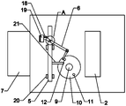
图1为本发明喷洒装置的结构示意图;
图2为本发明喷洒装置的一种工作状态俯视图;
图3为本发明喷洒装置的另一种工作状态俯视图;
图4为本发明图2中A处的放大结构示意图。
图中:1、喷洒装置本体;2、进水口;3、支架;4、固定板;5、活动板;6、L形摇杆;7、第一电机;8、第二电机;9、转动轴;10、圆盘;11、第一竖杆;12、第二竖杆;13、支撑柱;14、套筒;15、滚轮;16、连接管;17、水泵;18、出水管;19、喷头;20、导轨;21、固定杆;22、螺钉。
下面将结合本发明实施例中的附图,对本发明实施例中的技术方案进行清楚、完整地描述,显然,所描述的实施例仅仅是本发明一部分实施例,而不是全部的实施例。基于本发明中的实施例,本领域普通技术人员在没有做出创造性劳动前提下所获得的所有其他实施例,都属于本发明保护的范围。
请参阅图1-4,一种角度可控且覆盖均匀的农业喷洒装置,包括喷洒装置本体1,喷洒装置本体1的上部设置有进水口2,喷洒装置本体1的上部固定连接有支架3,支架3的上部焊接有固定板4,固定板4的上部活动连接有活动板5,活动板5的中部铰接有L形摇杆6,L形摇杆6在其转动中心位置处自由摆动,喷洒装置本体1的上部设置有第二电机8,第二电机8的上部固定连接有转动轴9,转动轴9的上部固定连接有圆盘10,圆盘10逆时针转动,圆盘10的转速恒定。圆盘10的上部左端固定连接有第一竖杆11,圆盘10的上部右端固定连接有第二竖杆12,第一竖杆11与第二竖杆12以圆盘10的圆心位置对称布置,L形摇杆6和固定杆21均位于圆盘10的上方,L形摇杆6和固定杆21两者均可以触碰到第一竖杆11、第二竖杆12,可以使圆盘10转动的过程中,第一竖杆11与第二竖杆12均能拨动到L形摇杆6和固定杆21,实现第一竖杆11与第二竖杆12的不断交替工作。喷洒装置本体1的上部固定连接有连接管16,连接管16的上部设置有水泵17,水泵17的上部固定连接有出水管18,出水管18远离水泵17的一端设置有喷头19,喷洒装置本体1的左部设置有第一电机7,喷洒装置本体1的底部焊接有支撑柱13,支撑柱13的下部滑动连接有套筒14,套筒14的内部设置有环形弹簧,支撑柱13与套筒14的内壁滑动连接,套筒14的底部固定连接有滚轮15,滚轮15的内部设置有驱动电机,且其内部的驱动电机与第一电机7电连接,通过支撑柱13和环形弹簧之间相互配合,实现了对滚轮15进行减震的功能,避免了由于农田地形不平不便前进的问题,提高了装置减震性。活动板5的左右两侧设置 有导轨20,导轨20的数量设置为两组,导轨20在活动板5的左右两侧对称布置,导轨20与活动板5滑动连接,导轨20的厚度小于活动板5的厚度,保证活动板5运动时,导轨20不会影响到L形摇杆6的上下移动。活动板5的右端固定连接有固定杆21,活动板5的上表面螺纹连接有螺钉22,L形摇杆6与活动板5的铰接处,在其表面设置有扁形凹槽,该扁形凹槽贯穿L形摇杆6,L形摇杆6与活动板5通过螺钉22螺纹连接铰接在一起。铰接可以使L形摇杆6与活动板5之间的扭矩较小,提高了使用寿命,降低能量损耗。
工作原理:启动第一电机7,滚轮15转动,使该喷洒装置前进。然后启动第二电机8,在第二电机8的作用下,转动轴9带动圆盘10逆时针转动,由于L形摇杆6和固定杆21均位于圆盘10的上方,L形摇杆6和固定杆21两者均可以触碰到第一竖杆11、第二竖杆12,圆盘10上的第一竖杆11、第二竖杆12会拨动L形摇杆6、固定杆21进行摆动,当第二竖杆12碰到L形摇杆6时,会拨动L形摇杆6偏转,喷头19向上移动;随着圆盘10的转动,当第二竖杆12碰到固定杆21后,拨动固定杆21带动活动板5向下移动,由于L形摇杆6与活动板5铰接,且L形摇杆6的回转中心位置固定,随着活动板5的向下移动,同时也会驱使L形摇杆6向下偏转,喷头19向下移动,当第二竖杆12在要远离固定杆21时,第一竖杆11会逐渐靠近L形摇杆6,实现了第一竖杆11与第二竖杆12的不断交替工作。活动板5的上下移动,从而使L形摇杆6上的喷头19上下移动,使得喷头19的喷洒角度及喷洒位置的改变,喷洒的范围变大,适用大面积的喷洒,保证了喷头19上多个喷水口能够均匀的进行对农作物的喷洒。
综上所述,该喷洒装置通过设置的转动轴9,在第二电机8的作用下,能带动圆盘10转动,圆盘10上的第一竖杆11、第二竖杆12会拨动L形摇杆6、固定杆21进行摆动,促使活动板5的上下移动,从而使L形摇杆6上的喷头19上下移动,使得喷头19的喷洒角度及喷洒位置的改变,保证了喷头19 能够均匀的进行对农作物的喷洒。在喷头19的横向位置设置多个喷水口,实现对农作物进行大面积喷洒的功能,避免了常用喷洒设备只设置一个喷水口导致喷洒面积过小,喷洒浇灌效率低的问题,提高了装置的高效性。
尽管已经示出和描述了本发明的实施例,对于本领域的普通技术人员而言,可以理解在不脱离本发明的原理和精神的情况下可以对这些实施例进行多种变化、修改、替换和变型,本发明的范围由所附权利要求及其等同物限定。
Claims (7)
- 一种角度可控且覆盖均匀的农业喷洒装置,包括喷洒装置本体(1),其特征在于:所述喷洒装置本体(1)的上部设置有进水口(2),所述喷洒装置本体(1)的上部固定连接有支架(3),所述支架(3)的上部焊接有固定板(4),所述固定板(4)的上部活动连接有活动板(5),所述活动板(5)的中部铰接有L形摇杆(6),所述喷洒装置本体(1)的上部设置有第二电机(8),所述第二电机(8)的上部固定连接有转动轴(9),所述转动轴(9)的上部固定连接有圆盘(10),所述圆盘(10)的上部左端固定连接有第一竖杆(11),所述圆盘(10)的上部右端固定连接有第二竖杆(12),所述喷洒装置本体(1)的上部固定连接有连接管(16),所述连接管(16)的上部设置有水泵(17),所述水泵(17)的上部固定连接有出水管(18),所述出水管(18)远离水泵(17)的一端设置有喷头(19),所述喷洒装置本体(1)的左部设置有第一电机(7),所述喷洒装置本体(1)的底部焊接有支撑柱(13),所述支撑柱(13)的下部滑动连接有套筒(14),所述套筒(14)的底部固定连接有滚轮(15),所述活动板(5)的左右两侧设置有导轨(20),所述活动板(5)的右端固定连接有固定杆(21),所述活动板(5)的上表面螺纹连接有螺钉(22)。
- 根据权利要求1所述的一种角度可控且覆盖均匀的农业喷洒装置,其特征在于:所述套筒(14)的内部设置有环形弹簧,所述支撑柱(13)与套筒(14)的内壁滑动连接。
- 根据权利要求1所述的一种角度可控且覆盖均匀的农业喷洒装置,其特征在于:所述第一竖杆(11)与第二竖杆(12)以圆盘(10)的圆心位置对称布置,所述L形摇杆(6)和固定杆(21)均位于圆盘(10)的上方,所述L形摇杆(6)和固定杆(21)两者均可以触碰到第一竖杆(11)、第二竖杆(12)。
- 根据权利要求1所述的一种角度可控且覆盖均匀的农业喷洒装置,其特征在于:所述导轨(20)的数量设置为两组,所述导轨(20)在活动板 (5)的左右两侧对称布置,所述导轨(20)与活动板(5)滑动连接,所述导轨(20)的厚度小于活动板(5)的厚度。
- 根据权利要求1所述的一种角度可控且覆盖均匀的农业喷洒装置,其特征在于:所述L形摇杆(6)与活动板(5)的铰接处,在其表面设置有扁形凹槽,该扁形凹槽贯穿L形摇杆(6),所述L形摇杆(6)与活动板(5)通过螺钉(22)螺纹连接铰接在一起。
- 根据权利要求1所述的一种角度可控且覆盖均匀的农业喷洒装置,其特征在于:所述圆盘(10)逆时针转动。
- 根据权利要求1所述的一种角度可控且覆盖均匀的农业喷洒装置,其特征在于:所述滚轮(15)的内部设置有驱动电机,且其内部的驱动电机与第一电机(7)电连接。
Priority Applications (1)
| Application Number | Priority Date | Filing Date | Title |
|---|---|---|---|
| PCT/CN2020/133182 WO2022116016A1 (zh) | 2020-12-01 | 2020-12-01 | 一种角度可控且覆盖均匀的农业喷洒装置 |
Applications Claiming Priority (1)
| Application Number | Priority Date | Filing Date | Title |
|---|---|---|---|
| PCT/CN2020/133182 WO2022116016A1 (zh) | 2020-12-01 | 2020-12-01 | 一种角度可控且覆盖均匀的农业喷洒装置 |
Publications (1)
| Publication Number | Publication Date |
|---|---|
| WO2022116016A1 true WO2022116016A1 (zh) | 2022-06-09 |
Family
ID=81853721
Family Applications (1)
| Application Number | Title | Priority Date | Filing Date |
|---|---|---|---|
| PCT/CN2020/133182 WO2022116016A1 (zh) | 2020-12-01 | 2020-12-01 | 一种角度可控且覆盖均匀的农业喷洒装置 |
Country Status (1)
| Country | Link |
|---|---|
| WO (1) | WO2022116016A1 (zh) |
Cited By (6)
| Publication number | Priority date | Publication date | Assignee | Title |
|---|---|---|---|---|
| CN115281061A (zh) * | 2022-09-15 | 2022-11-04 | 济南城市建设集团有限公司 | 一种绿色节能环保的园林景观用灌溉设备 |
| CN115316231A (zh) * | 2022-09-16 | 2022-11-11 | 河南水谷科技有限公司 | 一种节水灌溉设备及其操作方法 |
| CN115462356A (zh) * | 2022-08-30 | 2022-12-13 | 郭利方 | 一种具有多角度喷洒功能的农业生产用农药喷洒装置 |
| CN116941446A (zh) * | 2023-09-07 | 2023-10-27 | 浙江昱曜环境艺术有限公司 | 一种具有降低二氧化碳功能的自动灌溉道路花箱 |
| CN117310732A (zh) * | 2023-11-30 | 2023-12-29 | 柒零叁信息科技有限公司 | 工程测量系统及激光测距仪 |
| CN117534512A (zh) * | 2023-11-19 | 2024-02-09 | 黑龙江省黑土保护利用研究院 | 一种用于在秸秆堆腐水分调控的喷洒结构 |
Citations (6)
| Publication number | Priority date | Publication date | Assignee | Title |
|---|---|---|---|---|
| JPH09225353A (ja) * | 1996-02-21 | 1997-09-02 | Yuukiyan Kk | 噴霧装置 |
| CN207574202U (zh) * | 2017-12-01 | 2018-07-06 | 新疆天业智慧农业科技有限公司 | 一种灌溉均匀的农业喷灌装置 |
| CN207979419U (zh) * | 2017-07-20 | 2018-10-19 | 盐城方正医药科技有限公司 | 一种医药用摆放架 |
| CN109005842A (zh) * | 2018-09-17 | 2018-12-18 | 马骏 | 一种农业用全方位洒水施肥设备 |
| CN208972227U (zh) * | 2018-08-03 | 2019-06-14 | 北京富乐丰农机装备制造厂 | 一种基于电机驱动的摆动式农业喷灌喷洒装置 |
| CN110122013A (zh) * | 2019-06-27 | 2019-08-16 | 马鞍山聚力科技有限公司 | 一种可控施肥量的农业施肥装置 |
-
2020
- 2020-12-01 WO PCT/CN2020/133182 patent/WO2022116016A1/zh active Application Filing
Patent Citations (6)
| Publication number | Priority date | Publication date | Assignee | Title |
|---|---|---|---|---|
| JPH09225353A (ja) * | 1996-02-21 | 1997-09-02 | Yuukiyan Kk | 噴霧装置 |
| CN207979419U (zh) * | 2017-07-20 | 2018-10-19 | 盐城方正医药科技有限公司 | 一种医药用摆放架 |
| CN207574202U (zh) * | 2017-12-01 | 2018-07-06 | 新疆天业智慧农业科技有限公司 | 一种灌溉均匀的农业喷灌装置 |
| CN208972227U (zh) * | 2018-08-03 | 2019-06-14 | 北京富乐丰农机装备制造厂 | 一种基于电机驱动的摆动式农业喷灌喷洒装置 |
| CN109005842A (zh) * | 2018-09-17 | 2018-12-18 | 马骏 | 一种农业用全方位洒水施肥设备 |
| CN110122013A (zh) * | 2019-06-27 | 2019-08-16 | 马鞍山聚力科技有限公司 | 一种可控施肥量的农业施肥装置 |
Cited By (11)
| Publication number | Priority date | Publication date | Assignee | Title |
|---|---|---|---|---|
| CN115462356A (zh) * | 2022-08-30 | 2022-12-13 | 郭利方 | 一种具有多角度喷洒功能的农业生产用农药喷洒装置 |
| CN115462356B (zh) * | 2022-08-30 | 2024-01-23 | 郭利方 | 一种具有多角度喷洒功能的农业生产用农药喷洒装置 |
| CN115281061A (zh) * | 2022-09-15 | 2022-11-04 | 济南城市建设集团有限公司 | 一种绿色节能环保的园林景观用灌溉设备 |
| CN115281061B (zh) * | 2022-09-15 | 2023-06-27 | 济南城市建设集团有限公司 | 一种绿色节能环保的园林景观用灌溉设备 |
| CN115316231A (zh) * | 2022-09-16 | 2022-11-11 | 河南水谷科技有限公司 | 一种节水灌溉设备及其操作方法 |
| CN115316231B (zh) * | 2022-09-16 | 2024-01-30 | 河南水谷科技有限公司 | 一种节水灌溉设备及其操作方法 |
| CN116941446A (zh) * | 2023-09-07 | 2023-10-27 | 浙江昱曜环境艺术有限公司 | 一种具有降低二氧化碳功能的自动灌溉道路花箱 |
| CN117534512A (zh) * | 2023-11-19 | 2024-02-09 | 黑龙江省黑土保护利用研究院 | 一种用于在秸秆堆腐水分调控的喷洒结构 |
| CN117534512B (zh) * | 2023-11-19 | 2024-04-12 | 黑龙江省黑土保护利用研究院 | 一种用于在秸秆堆腐水分调控的喷洒结构 |
| CN117310732A (zh) * | 2023-11-30 | 2023-12-29 | 柒零叁信息科技有限公司 | 工程测量系统及激光测距仪 |
| CN117310732B (zh) * | 2023-11-30 | 2024-02-13 | 柒零叁信息科技有限公司 | 激光测距仪 |
Similar Documents
| Publication | Publication Date | Title |
|---|---|---|
| WO2022116016A1 (zh) | 一种角度可控且覆盖均匀的农业喷洒装置 | |
| CN206674698U (zh) | 一种农田洒水装置 | |
| CN109328999B (zh) | 一种可调节喷洒域形状的喷灌机 | |
| CN209549744U (zh) | 一种农业灌溉用可控角度摇臂喷头 | |
| CN208597048U (zh) | 一种提高太阳能转化率的光伏发电装置 | |
| CN208191685U (zh) | 一种节水灌溉装置 | |
| CN110788066A (zh) | 一种二自由度便携式洗根机 | |
| CN209314497U (zh) | 一种农业节水灌溉装置 | |
| CN205926082U (zh) | 一种灌溉喷头 | |
| CN208891367U (zh) | 一种农业灌溉装置 | |
| CN107646638A (zh) | 一种农业灌溉运输车 | |
| CN107347442A (zh) | 一种移动式食用菌浇水车 | |
| CN207118426U (zh) | 一种农业水利灌溉装置 | |
| CN206835806U (zh) | 一种农田喷灌机 | |
| CN215582807U (zh) | 一种农业园林用节水浇灌装置 | |
| CN213625411U (zh) | 一种建筑施工作业面喷淋降尘降温装置 | |
| CN214071043U (zh) | 一种农田水利喷灌装置 | |
| CN210288246U (zh) | 一种作用范围可调的建筑施工用降尘装置 | |
| CN204376808U (zh) | 太阳能移动发电车 | |
| CN208370546U (zh) | 一种新型园林专用洒水装置 | |
| CN212087397U (zh) | 一种新型环卫用电动喷雾洒水装置 | |
| CN215593605U (zh) | 一种市政用道路养护洒水装置 | |
| CN218353090U (zh) | 一种园林绿化土壤用的治理装置 | |
| CN114451268B (zh) | 一种农业自动可调节式喷灌设备 | |
| CN111280021A (zh) | 一种农田水利用喷洒装置 |
Legal Events
| Date | Code | Title | Description |
|---|---|---|---|
| 121 | Ep: the epo has been informed by wipo that ep was designated in this application |
Ref document number: 20963864 Country of ref document: EP Kind code of ref document: A1 |
|
| NENP | Non-entry into the national phase |
Ref country code: DE |
|
| 122 | Ep: pct application non-entry in european phase |
Ref document number: 20963864 Country of ref document: EP Kind code of ref document: A1 |
|
| 122 | Ep: pct application non-entry in european phase |
Ref document number: 20963864 Country of ref document: EP Kind code of ref document: A1 |