WO2022114225A1 - Rotary member and method for manufacturing same - Google Patents
Rotary member and method for manufacturing same Download PDFInfo
- Publication number
- WO2022114225A1 WO2022114225A1 PCT/JP2021/043891 JP2021043891W WO2022114225A1 WO 2022114225 A1 WO2022114225 A1 WO 2022114225A1 JP 2021043891 W JP2021043891 W JP 2021043891W WO 2022114225 A1 WO2022114225 A1 WO 2022114225A1
- Authority
- WO
- WIPO (PCT)
- Prior art keywords
- carbon fiber
- cnt
- carbon
- rotating member
- fiber
- Prior art date
Links
- 238000000034 method Methods 0.000 title claims abstract description 38
- 238000004519 manufacturing process Methods 0.000 title claims abstract description 20
- 229920000049 Carbon (fiber) Polymers 0.000 claims abstract description 377
- 239000004917 carbon fiber Substances 0.000 claims abstract description 377
- VNWKTOKETHGBQD-UHFFFAOYSA-N methane Chemical compound C VNWKTOKETHGBQD-UHFFFAOYSA-N 0.000 claims abstract description 256
- 238000004513 sizing Methods 0.000 claims abstract description 149
- 239000002041 carbon nanotube Substances 0.000 claims abstract description 112
- 239000003795 chemical substances by application Substances 0.000 claims abstract description 107
- OKTJSMMVPCPJKN-UHFFFAOYSA-N Carbon Chemical compound [C] OKTJSMMVPCPJKN-UHFFFAOYSA-N 0.000 claims abstract description 24
- 229910021393 carbon nanotube Inorganic materials 0.000 claims abstract description 18
- 238000000465 moulding Methods 0.000 claims abstract description 11
- VPKDCDLSJZCGKE-UHFFFAOYSA-N carbodiimide group Chemical group N=C=N VPKDCDLSJZCGKE-UHFFFAOYSA-N 0.000 claims abstract description 4
- 229920005989 resin Polymers 0.000 claims description 122
- 239000011347 resin Substances 0.000 claims description 122
- 239000000835 fiber Substances 0.000 claims description 108
- 239000007788 liquid Substances 0.000 claims description 92
- 239000011159 matrix material Substances 0.000 claims description 85
- 239000006185 dispersion Substances 0.000 claims description 52
- 238000011282 treatment Methods 0.000 claims description 45
- -1 carbodiimide compound Chemical class 0.000 claims description 23
- 238000004804 winding Methods 0.000 claims description 11
- 238000004132 cross linking Methods 0.000 claims description 2
- 239000002131 composite material Substances 0.000 abstract description 108
- 239000012783 reinforcing fiber Substances 0.000 abstract description 16
- 125000000524 functional group Chemical group 0.000 abstract description 9
- 150000001718 carbodiimides Chemical class 0.000 abstract description 6
- 238000006243 chemical reaction Methods 0.000 abstract description 5
- 238000012360 testing method Methods 0.000 description 120
- 238000005259 measurement Methods 0.000 description 61
- 238000010438 heat treatment Methods 0.000 description 60
- 230000000052 comparative effect Effects 0.000 description 33
- 239000000463 material Substances 0.000 description 19
- 239000010410 layer Substances 0.000 description 15
- 239000011229 interlayer Substances 0.000 description 14
- 239000000853 adhesive Substances 0.000 description 13
- 230000001070 adhesive effect Effects 0.000 description 13
- CSCPPACGZOOCGX-UHFFFAOYSA-N Acetone Chemical compound CC(C)=O CSCPPACGZOOCGX-UHFFFAOYSA-N 0.000 description 12
- 238000005452 bending Methods 0.000 description 12
- 239000002612 dispersion medium Substances 0.000 description 10
- 239000003822 epoxy resin Substances 0.000 description 10
- 229920000647 polyepoxide Polymers 0.000 description 10
- 239000000243 solution Substances 0.000 description 9
- PPBRXRYQALVLMV-UHFFFAOYSA-N Styrene Chemical compound C=CC1=CC=CC=C1 PPBRXRYQALVLMV-UHFFFAOYSA-N 0.000 description 8
- 239000002270 dispersing agent Substances 0.000 description 8
- 230000005484 gravity Effects 0.000 description 8
- 230000002093 peripheral effect Effects 0.000 description 8
- 229920001187 thermosetting polymer Polymers 0.000 description 8
- 238000002835 absorbance Methods 0.000 description 7
- 238000011156 evaluation Methods 0.000 description 7
- 239000011259 mixed solution Substances 0.000 description 7
- ZWEHNKRNPOVVGH-UHFFFAOYSA-N 2-Butanone Chemical compound CCC(C)=O ZWEHNKRNPOVVGH-UHFFFAOYSA-N 0.000 description 6
- 230000007423 decrease Effects 0.000 description 6
- 238000002474 experimental method Methods 0.000 description 6
- 238000000445 field-emission scanning electron microscopy Methods 0.000 description 6
- XLYOFNOQVPJJNP-UHFFFAOYSA-N water Substances O XLYOFNOQVPJJNP-UHFFFAOYSA-N 0.000 description 6
- 229910052799 carbon Inorganic materials 0.000 description 5
- 230000008859 change Effects 0.000 description 5
- 230000008602 contraction Effects 0.000 description 5
- 238000005520 cutting process Methods 0.000 description 5
- 238000001035 drying Methods 0.000 description 5
- 238000007654 immersion Methods 0.000 description 5
- 238000013001 point bending Methods 0.000 description 5
- 229920005992 thermoplastic resin Polymers 0.000 description 5
- 239000011800 void material Substances 0.000 description 5
- NLHHRLWOUZZQLW-UHFFFAOYSA-N Acrylonitrile Chemical compound C=CC#N NLHHRLWOUZZQLW-UHFFFAOYSA-N 0.000 description 4
- KAKZBPTYRLMSJV-UHFFFAOYSA-N Butadiene Chemical compound C=CC=C KAKZBPTYRLMSJV-UHFFFAOYSA-N 0.000 description 4
- LFQSCWFLJHTTHZ-UHFFFAOYSA-N Ethanol Chemical compound CCO LFQSCWFLJHTTHZ-UHFFFAOYSA-N 0.000 description 4
- SECXISVLQFMRJM-UHFFFAOYSA-N N-Methylpyrrolidone Chemical compound CN1CCCC1=O SECXISVLQFMRJM-UHFFFAOYSA-N 0.000 description 4
- WYURNTSHIVDZCO-UHFFFAOYSA-N Tetrahydrofuran Chemical compound C1CCOC1 WYURNTSHIVDZCO-UHFFFAOYSA-N 0.000 description 4
- 229920001807 Urea-formaldehyde Polymers 0.000 description 4
- 229920006351 engineering plastic Polymers 0.000 description 4
- 238000007656 fracture toughness test Methods 0.000 description 4
- 239000000203 mixture Substances 0.000 description 4
- VLKZOEOYAKHREP-UHFFFAOYSA-N n-Hexane Chemical compound CCCCCC VLKZOEOYAKHREP-UHFFFAOYSA-N 0.000 description 4
- 239000004745 nonwoven fabric Substances 0.000 description 4
- 239000002904 solvent Substances 0.000 description 4
- 238000003860 storage Methods 0.000 description 4
- 239000004094 surface-active agent Substances 0.000 description 4
- XEKOWRVHYACXOJ-UHFFFAOYSA-N Ethyl acetate Chemical compound CCOC(C)=O XEKOWRVHYACXOJ-UHFFFAOYSA-N 0.000 description 3
- KFZMGEQAYNKOFK-UHFFFAOYSA-N Isopropanol Chemical compound CC(C)O KFZMGEQAYNKOFK-UHFFFAOYSA-N 0.000 description 3
- OKKJLVBELUTLKV-UHFFFAOYSA-N Methanol Chemical compound OC OKKJLVBELUTLKV-UHFFFAOYSA-N 0.000 description 3
- BGPVFRJUHWVFKM-UHFFFAOYSA-N N1=C2C=CC=CC2=[N+]([O-])C1(CC1)CCC21N=C1C=CC=CC1=[N+]2[O-] Chemical compound N1=C2C=CC=CC2=[N+]([O-])C1(CC1)CCC21N=C1C=CC=CC1=[N+]2[O-] BGPVFRJUHWVFKM-UHFFFAOYSA-N 0.000 description 3
- 239000004642 Polyimide Substances 0.000 description 3
- YXFVVABEGXRONW-UHFFFAOYSA-N Toluene Chemical compound CC1=CC=CC=C1 YXFVVABEGXRONW-UHFFFAOYSA-N 0.000 description 3
- 230000015572 biosynthetic process Effects 0.000 description 3
- 239000004918 carbon fiber reinforced polymer Substances 0.000 description 3
- 239000004643 cyanate ester Substances 0.000 description 3
- 238000009730 filament winding Methods 0.000 description 3
- 230000009477 glass transition Effects 0.000 description 3
- 229930195733 hydrocarbon Natural products 0.000 description 3
- 239000004417 polycarbonate Substances 0.000 description 3
- 229920000515 polycarbonate Polymers 0.000 description 3
- 229920001721 polyimide Polymers 0.000 description 3
- 239000000126 substance Substances 0.000 description 3
- 238000010998 test method Methods 0.000 description 3
- 239000004215 Carbon black (E152) Substances 0.000 description 2
- RTZKZFJDLAIYFH-UHFFFAOYSA-N Diethyl ether Chemical compound CCOCC RTZKZFJDLAIYFH-UHFFFAOYSA-N 0.000 description 2
- 229920000106 Liquid crystal polymer Polymers 0.000 description 2
- 239000004977 Liquid-crystal polymers (LCPs) Substances 0.000 description 2
- 239000004640 Melamine resin Substances 0.000 description 2
- 229920000877 Melamine resin Polymers 0.000 description 2
- 239000004696 Poly ether ether ketone Substances 0.000 description 2
- 239000004698 Polyethylene Substances 0.000 description 2
- 239000004734 Polyphenylene sulfide Substances 0.000 description 2
- 239000004743 Polypropylene Substances 0.000 description 2
- 239000004793 Polystyrene Substances 0.000 description 2
- QAOWNCQODCNURD-UHFFFAOYSA-N Sulfuric acid Chemical compound OS(O)(=O)=O QAOWNCQODCNURD-UHFFFAOYSA-N 0.000 description 2
- 238000005411 Van der Waals force Methods 0.000 description 2
- 229920000122 acrylonitrile butadiene styrene Polymers 0.000 description 2
- 229920000180 alkyd Polymers 0.000 description 2
- 238000004458 analytical method Methods 0.000 description 2
- 238000011088 calibration curve Methods 0.000 description 2
- 125000003178 carboxy group Chemical group [H]OC(*)=O 0.000 description 2
- 150000001875 compounds Chemical class 0.000 description 2
- 239000003431 cross linking reagent Substances 0.000 description 2
- 230000006378 damage Effects 0.000 description 2
- 238000013016 damping Methods 0.000 description 2
- 230000007547 defect Effects 0.000 description 2
- 208000037265 diseases, disorders, signs and symptoms Diseases 0.000 description 2
- 230000000694 effects Effects 0.000 description 2
- 238000010304 firing Methods 0.000 description 2
- 238000013467 fragmentation Methods 0.000 description 2
- 238000006062 fragmentation reaction Methods 0.000 description 2
- 150000002430 hydrocarbons Chemical class 0.000 description 2
- 238000005470 impregnation Methods 0.000 description 2
- 230000006872 improvement Effects 0.000 description 2
- 230000007246 mechanism Effects 0.000 description 2
- 239000000113 methacrylic resin Substances 0.000 description 2
- 230000003647 oxidation Effects 0.000 description 2
- 238000007254 oxidation reaction Methods 0.000 description 2
- 239000005011 phenolic resin Substances 0.000 description 2
- 229920003229 poly(methyl methacrylate) Polymers 0.000 description 2
- 229920001230 polyarylate Polymers 0.000 description 2
- 229920002530 polyetherether ketone Polymers 0.000 description 2
- 229920001601 polyetherimide Polymers 0.000 description 2
- 229920000573 polyethylene Polymers 0.000 description 2
- 229920000139 polyethylene terephthalate Polymers 0.000 description 2
- 239000004926 polymethyl methacrylate Substances 0.000 description 2
- 229920006324 polyoxymethylene Polymers 0.000 description 2
- 229920000069 polyphenylene sulfide Polymers 0.000 description 2
- 229920001155 polypropylene Polymers 0.000 description 2
- 229920002223 polystyrene Polymers 0.000 description 2
- 239000004810 polytetrafluoroethylene Substances 0.000 description 2
- 229920001343 polytetrafluoroethylene Polymers 0.000 description 2
- 230000008569 process Effects 0.000 description 2
- 230000003014 reinforcing effect Effects 0.000 description 2
- 230000002441 reversible effect Effects 0.000 description 2
- 238000010008 shearing Methods 0.000 description 2
- 239000007787 solid Substances 0.000 description 2
- 238000009864 tensile test Methods 0.000 description 2
- YLQBMQCUIZJEEH-UHFFFAOYSA-N tetrahydrofuran Natural products C=1C=COC=1 YLQBMQCUIZJEEH-UHFFFAOYSA-N 0.000 description 2
- 229920001169 thermoplastic Polymers 0.000 description 2
- 239000004416 thermosoftening plastic Substances 0.000 description 2
- 229920000785 ultra high molecular weight polyethylene Polymers 0.000 description 2
- 229920006305 unsaturated polyester Polymers 0.000 description 2
- XQUPVDVFXZDTLT-UHFFFAOYSA-N 1-[4-[[4-(2,5-dioxopyrrol-1-yl)phenyl]methyl]phenyl]pyrrole-2,5-dione Chemical compound O=C1C=CC(=O)N1C(C=C1)=CC=C1CC1=CC=C(N2C(C=CC2=O)=O)C=C1 XQUPVDVFXZDTLT-UHFFFAOYSA-N 0.000 description 1
- 229910000975 Carbon steel Inorganic materials 0.000 description 1
- 229920000298 Cellophane Polymers 0.000 description 1
- 241000196324 Embryophyta Species 0.000 description 1
- 229920002430 Fibre-reinforced plastic Polymers 0.000 description 1
- GRYLNZFGIOXLOG-UHFFFAOYSA-N Nitric acid Chemical compound O[N+]([O-])=O GRYLNZFGIOXLOG-UHFFFAOYSA-N 0.000 description 1
- CTQNGGLPUBDAKN-UHFFFAOYSA-N O-Xylene Chemical compound CC1=CC=CC=C1C CTQNGGLPUBDAKN-UHFFFAOYSA-N 0.000 description 1
- 240000007594 Oryza sativa Species 0.000 description 1
- 235000007164 Oryza sativa Nutrition 0.000 description 1
- CBENFWSGALASAD-UHFFFAOYSA-N Ozone Chemical compound [O-][O+]=O CBENFWSGALASAD-UHFFFAOYSA-N 0.000 description 1
- 229930182556 Polyacetal Natural products 0.000 description 1
- 239000004952 Polyamide Substances 0.000 description 1
- 239000004697 Polyetherimide Substances 0.000 description 1
- XBDQKXXYIPTUBI-UHFFFAOYSA-M Propionate Chemical compound CCC([O-])=O XBDQKXXYIPTUBI-UHFFFAOYSA-M 0.000 description 1
- 229920000297 Rayon Polymers 0.000 description 1
- 239000004699 Ultra-high molecular weight polyethylene Substances 0.000 description 1
- BZHJMEDXRYGGRV-UHFFFAOYSA-N Vinyl chloride Chemical compound ClC=C BZHJMEDXRYGGRV-UHFFFAOYSA-N 0.000 description 1
- KXKVLQRXCPHEJC-UHFFFAOYSA-N acetic acid trimethyl ester Natural products COC(C)=O KXKVLQRXCPHEJC-UHFFFAOYSA-N 0.000 description 1
- 239000002253 acid Substances 0.000 description 1
- 238000004220 aggregation Methods 0.000 description 1
- 230000002776 aggregation Effects 0.000 description 1
- 150000001298 alcohols Chemical class 0.000 description 1
- 150000001338 aliphatic hydrocarbons Chemical class 0.000 description 1
- 150000004945 aromatic hydrocarbons Chemical class 0.000 description 1
- 230000005540 biological transmission Effects 0.000 description 1
- 239000010962 carbon steel Substances 0.000 description 1
- 239000003054 catalyst Substances 0.000 description 1
- 239000003245 coal Substances 0.000 description 1
- 239000011280 coal tar Substances 0.000 description 1
- 239000011248 coating agent Substances 0.000 description 1
- 238000001816 cooling Methods 0.000 description 1
- 230000001066 destructive effect Effects 0.000 description 1
- 230000006866 deterioration Effects 0.000 description 1
- 238000006073 displacement reaction Methods 0.000 description 1
- 238000009826 distribution Methods 0.000 description 1
- 230000005489 elastic deformation Effects 0.000 description 1
- 239000011151 fibre-reinforced plastic Substances 0.000 description 1
- 238000001879 gelation Methods 0.000 description 1
- 238000007429 general method Methods 0.000 description 1
- 125000002887 hydroxy group Chemical group [H]O* 0.000 description 1
- 239000012535 impurity Substances 0.000 description 1
- 230000003993 interaction Effects 0.000 description 1
- 238000002955 isolation Methods 0.000 description 1
- 150000002576 ketones Chemical class 0.000 description 1
- 230000001404 mediated effect Effects 0.000 description 1
- 229910017604 nitric acid Inorganic materials 0.000 description 1
- 150000002825 nitriles Chemical class 0.000 description 1
- 238000012856 packing Methods 0.000 description 1
- 239000003208 petroleum Substances 0.000 description 1
- 229920006287 phenoxy resin Polymers 0.000 description 1
- 239000013034 phenoxy resin Substances 0.000 description 1
- 239000011295 pitch Substances 0.000 description 1
- 229920003192 poly(bis maleimide) Polymers 0.000 description 1
- 229920001652 poly(etherketoneketone) Polymers 0.000 description 1
- 229920002647 polyamide Polymers 0.000 description 1
- 239000005020 polyethylene terephthalate Substances 0.000 description 1
- 229920000642 polymer Polymers 0.000 description 1
- 239000004800 polyvinyl chloride Substances 0.000 description 1
- 229920000915 polyvinyl chloride Polymers 0.000 description 1
- 230000036544 posture Effects 0.000 description 1
- 238000003825 pressing Methods 0.000 description 1
- 238000012545 processing Methods 0.000 description 1
- 239000010453 quartz Substances 0.000 description 1
- 239000002964 rayon Substances 0.000 description 1
- 230000004044 response Effects 0.000 description 1
- 235000009566 rice Nutrition 0.000 description 1
- 102200082816 rs34868397 Human genes 0.000 description 1
- VYPSYNLAJGMNEJ-UHFFFAOYSA-N silicon dioxide Inorganic materials O=[Si]=O VYPSYNLAJGMNEJ-UHFFFAOYSA-N 0.000 description 1
- 239000002356 single layer Substances 0.000 description 1
- 238000005507 spraying Methods 0.000 description 1
- 230000001629 suppression Effects 0.000 description 1
- 238000004154 testing of material Methods 0.000 description 1
- 230000007704 transition Effects 0.000 description 1
- 238000002834 transmittance Methods 0.000 description 1
- 229920001567 vinyl ester resin Polymers 0.000 description 1
- 239000002023 wood Substances 0.000 description 1
- 239000008096 xylene Substances 0.000 description 1
Images


Classifications
-
- H—ELECTRICITY
- H02—GENERATION; CONVERSION OR DISTRIBUTION OF ELECTRIC POWER
- H02K—DYNAMO-ELECTRIC MACHINES
- H02K1/00—Details of the magnetic circuit
- H02K1/06—Details of the magnetic circuit characterised by the shape, form or construction
- H02K1/22—Rotating parts of the magnetic circuit
- H02K1/28—Means for mounting or fastening rotating magnetic parts on to, or to, the rotor structures
-
- C—CHEMISTRY; METALLURGY
- C08—ORGANIC MACROMOLECULAR COMPOUNDS; THEIR PREPARATION OR CHEMICAL WORKING-UP; COMPOSITIONS BASED THEREON
- C08J—WORKING-UP; GENERAL PROCESSES OF COMPOUNDING; AFTER-TREATMENT NOT COVERED BY SUBCLASSES C08B, C08C, C08F, C08G or C08H
- C08J5/00—Manufacture of articles or shaped materials containing macromolecular substances
- C08J5/04—Reinforcing macromolecular compounds with loose or coherent fibrous material
- C08J5/0405—Reinforcing macromolecular compounds with loose or coherent fibrous material with inorganic fibres
- C08J5/042—Reinforcing macromolecular compounds with loose or coherent fibrous material with inorganic fibres with carbon fibres
-
- H—ELECTRICITY
- H02—GENERATION; CONVERSION OR DISTRIBUTION OF ELECTRIC POWER
- H02K—DYNAMO-ELECTRIC MACHINES
- H02K5/00—Casings; Enclosures; Supports
- H02K5/02—Casings or enclosures characterised by the material thereof
-
- C—CHEMISTRY; METALLURGY
- C08—ORGANIC MACROMOLECULAR COMPOUNDS; THEIR PREPARATION OR CHEMICAL WORKING-UP; COMPOSITIONS BASED THEREON
- C08J—WORKING-UP; GENERAL PROCESSES OF COMPOUNDING; AFTER-TREATMENT NOT COVERED BY SUBCLASSES C08B, C08C, C08F, C08G or C08H
- C08J5/00—Manufacture of articles or shaped materials containing macromolecular substances
- C08J5/005—Reinforced macromolecular compounds with nanosized materials, e.g. nanoparticles, nanofibres, nanotubes, nanowires, nanorods or nanolayered materials
-
- H—ELECTRICITY
- H02—GENERATION; CONVERSION OR DISTRIBUTION OF ELECTRIC POWER
- H02K—DYNAMO-ELECTRIC MACHINES
- H02K1/00—Details of the magnetic circuit
- H02K1/04—Details of the magnetic circuit characterised by the material used for insulating the magnetic circuit or parts thereof
-
- H—ELECTRICITY
- H02—GENERATION; CONVERSION OR DISTRIBUTION OF ELECTRIC POWER
- H02K—DYNAMO-ELECTRIC MACHINES
- H02K1/00—Details of the magnetic circuit
- H02K1/06—Details of the magnetic circuit characterised by the shape, form or construction
- H02K1/22—Rotating parts of the magnetic circuit
- H02K1/27—Rotor cores with permanent magnets
- H02K1/2706—Inner rotors
- H02K1/272—Inner rotors the magnetisation axis of the magnets being perpendicular to the rotor axis
- H02K1/274—Inner rotors the magnetisation axis of the magnets being perpendicular to the rotor axis the rotor consisting of two or more circumferentially positioned magnets
- H02K1/2753—Inner rotors the magnetisation axis of the magnets being perpendicular to the rotor axis the rotor consisting of two or more circumferentially positioned magnets the rotor consisting of magnets or groups of magnets arranged with alternating polarity
- H02K1/278—Surface mounted magnets; Inset magnets
-
- H—ELECTRICITY
- H02—GENERATION; CONVERSION OR DISTRIBUTION OF ELECTRIC POWER
- H02K—DYNAMO-ELECTRIC MACHINES
- H02K15/00—Methods or apparatus specially adapted for manufacturing, assembling, maintaining or repairing of dynamo-electric machines
- H02K15/02—Methods or apparatus specially adapted for manufacturing, assembling, maintaining or repairing of dynamo-electric machines of stator or rotor bodies
- H02K15/03—Methods or apparatus specially adapted for manufacturing, assembling, maintaining or repairing of dynamo-electric machines of stator or rotor bodies having permanent magnets
-
- H—ELECTRICITY
- H02—GENERATION; CONVERSION OR DISTRIBUTION OF ELECTRIC POWER
- H02K—DYNAMO-ELECTRIC MACHINES
- H02K15/00—Methods or apparatus specially adapted for manufacturing, assembling, maintaining or repairing of dynamo-electric machines
- H02K15/12—Impregnating, heating or drying of windings, stators, rotors or machines
-
- H—ELECTRICITY
- H02—GENERATION; CONVERSION OR DISTRIBUTION OF ELECTRIC POWER
- H02K—DYNAMO-ELECTRIC MACHINES
- H02K15/00—Methods or apparatus specially adapted for manufacturing, assembling, maintaining or repairing of dynamo-electric machines
- H02K15/14—Casings; Enclosures; Supports
-
- C—CHEMISTRY; METALLURGY
- C08—ORGANIC MACROMOLECULAR COMPOUNDS; THEIR PREPARATION OR CHEMICAL WORKING-UP; COMPOSITIONS BASED THEREON
- C08J—WORKING-UP; GENERAL PROCESSES OF COMPOUNDING; AFTER-TREATMENT NOT COVERED BY SUBCLASSES C08B, C08C, C08F, C08G or C08H
- C08J2300/00—Characterised by the use of unspecified polymers
-
- H—ELECTRICITY
- H02—GENERATION; CONVERSION OR DISTRIBUTION OF ELECTRIC POWER
- H02K—DYNAMO-ELECTRIC MACHINES
- H02K2213/00—Specific aspects, not otherwise provided for and not covered by codes H02K2201/00 - H02K2211/00
- H02K2213/03—Machines characterised by numerical values, ranges, mathematical expressions or similar information
Definitions
- the present invention relates to a rotating member and a method for manufacturing the same.
- a rotating member that rotates at high speed for example, a member that is externally fitted to a rotor of a surface magnet type motor is known (see, for example, Patent Document 1).
- the rotor of a surface magnet type motor has multiple permanent magnets built into its outer peripheral surface, and in order to prevent these permanent magnets from peeling off from the rotor and scattering due to centrifugal force, it is inside the hollow inside of the rotating member.
- the rotor is press-fitted. Since a force from a permanent magnet toward the outside in the radial direction acts on the rotating member, high tensile strength is required in the circumferential direction of the rotating member. Centrifugal force also acts on the mass of the rotating member itself.
- a rotating member a carbon fiber reinforced plastic made of carbon fiber as a reinforced fiber is also known.
- a rotating member that rotates at high speed there is also a cylindrical rotary cylinder of a centrifuge used for centrifuging.
- Rotating members made of carbon fiber reinforced plastic as described above are lightweight and have high tensile strength, but higher tensile strength is desired in response to higher speed rotation of surface magnet type motors and centrifuge. It is rare.
- An object of the present invention is to provide a rotating member having a higher tensile strength while being lightweight and a method for manufacturing the same.
- the rotating member of the present invention is composed of carbon fibers wound in the circumferential direction in the rotating member rotating along the circumferential direction, a matrix resin embedding the carbon fibers, and a plurality of curved carbon nanotubes having a bent portion. It is configured to form a network structure having contact portions in which the carbon nanotubes are in direct contact with each other, and includes a structure provided on the surface of the carbon fibers.
- carbon fibers having a bent shape having a bent portion are dispersed and carbon fibers are immersed in a dispersion liquid to which ultrasonic vibration is applied, and a plurality of the carbon nanotubes are placed in the carbon fibers.
- the carbon fiber coated with the matrix resin is wound around a mandrel, the matrix resin is cured, and then the mandrel is pulled out.
- the matrix resin embeds carbon fibers having a structure made of carbon nanotubes on the surface, it is possible to provide a rotating member which is lightweight but has higher tensile strength.
- 6 is an SEM photograph showing an adhesion state of the first sizing agent to a structure having a sizing agent mass ratio Rm of 0.8%.
- 6 is an SEM photograph showing an adhesion state of the first sizing agent to a structure having a sizing agent mass ratio Rm of 1.1%.
- 6 is an SEM photograph showing an adhesion state of the first sizing agent to a structure having a sizing agent mass ratio Rm of 1.5%.
- 6 is a graph showing the results of the NOL ring test in Example 6 and Comparative Example 6. It is a graph which enlarges and shows the region of the fiber volume content 60% or more, and the tensile strength (index value) 90 or more among the results of the NOL ring test in Example 6 and Comparative Example 6.
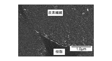
- 6 is an SEM photograph showing a cross section of an observation sample taken out from a ring test piece in Example 8.
- 6 is an SEM photograph showing a cross section of an observation sample taken out from a ring test piece in Comparative Example 8.
- 6 is an FE-SEM photograph showing a cross section of an observation sample taken out from a ring test piece in Example 8 in a further enlarged manner.
- 6 is an FE-SEM photograph showing a cross section of an observation sample taken out from a ring test piece in Comparative Example 8 in a further enlarged manner.
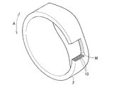
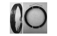
- FIG. 1 shows the rotating member 2 according to the embodiment.
- the rotating member 2 of this example is provided as a shatterproof member of the surface magnet type motor 3.
- the rotating member 2 is an annular body, in this example, a cylindrical shape.
- the rotating member 2 is externally fitted to the rotor 4. That is, the rotating member 2 is fixed by fitting the rotor 4 into its hollow interior by press fitting, and rotates integrally with the rotor 4. Therefore, the rotating member 2 rotates in the circumferential direction thereof.
- a plurality of permanent magnets 5 are embedded in the outer peripheral surface of the rotor 4 at predetermined intervals along the circumferential direction of the rotor 4.
- the rotating member 2 suppresses the permanent magnet 5 against the centrifugal force so that the permanent magnet 5 does not peel off and scatter outward in the radial direction due to the centrifugal force acting on the permanent magnet 5 when the rotor 4 rotates at high speed.
- the rotating member 2 may have a ring shape or the like having a narrow width (short length in the axial direction). Further, a plurality of ring-shaped objects having a narrow width may be used in combination.
- the rotating member 2 is a carbon fiber reinforced molded body (carbon) having a composite material 10 and a matrix resin M that embeds the carbon fiber 11 (see FIG. 3) of the composite material 10. Fiber reinforced plastic).
- the composite material 10 carbon fiber 11
- the composite material 10 is wound in the circumferential direction of the rotating member 2, that is, in the rotational direction (A direction in the drawing), and the plurality of composite materials 10 form one or more fiber layers in the radial direction of the rotating member 2. is doing.
- the fiber layer is composed of the composite material 10 closely arranged in the axial direction.
- the composite material 10 is wound in the circumferential direction of the rotating member 2.
- Winding in the circumferential direction of the rotating member 2 means that the composite material 10 has a component along the circumferential direction of the rotating member 2, that is, a predetermined oblique angle with respect to the axial direction of the rotating member 2. It means that it is wound at ( ⁇ 0 °). Therefore, as will be described later, the fiber layer is wound in a hoop (parallel winding) or around the axis so that the composite material 10 is wound around the outer peripheral surface of the mandrel so as to be substantially perpendicular to the axis (diagonal angle ⁇ 90 °).
- the oblique angle is for preventing the hoop layer from collapsing when the ring is assembled, and can be arbitrarily determined. When there are a plurality of fiber layers, the oblique angle can be determined for each fiber layer.
- each composite material 10 is drawn exaggeratedly, and the cross section of each composite material 10 is drawn in a circular shape so as to be distinguishable. It is not distinguishable.
- the composite material 10 includes a carbon fiber bundle 12 in which a plurality of continuous carbon fibers 11 are put together.
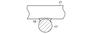
- a structure 14 is formed on the surface of each carbon fiber 11, and a first sizing agent 15 (see FIG. 4) is applied to the structure 14.
- the carbon fibers 11 constituting the carbon fiber bundle 12 are aligned in the fiber axial direction of each carbon fiber 11 without being substantially entangled with each other.
- the fiber axial direction is the axial direction (extended direction) of the carbon fiber 11.
- the carbon fiber bundle 12 is composed of 12,000 carbon fibers 11.
- the number of carbon fibers 11 constituting the carbon fiber bundle 12 is not particularly limited, but may be, for example, in the range of 10,000 or more and 100,000 or less. In FIG. 3, for convenience of illustration, only a dozen or so carbon fibers 11 are drawn.
- the composite material 10 is composed of a plurality of carbon fibers 11 having the structure 14 and the first sizing agent 15 as described above, but the composite material 10 is the structure 14 and the first sizing as described above. It may be one carbon fiber 11 having the agent 15.
- the fiber having the structure 14 formed on the surface may be referred to as a CNT composite fiber together with the structure 14.
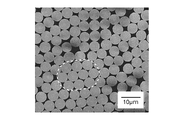
- the entanglement of the carbon fibers 11 in the carbon fiber bundle 12 can be evaluated by the degree of disturbance of the carbon fibers 11.
- the carbon fiber bundle 12 is observed at a constant magnification with a scanning electron microscope (SEM), and a predetermined number (for example, 10) is observed in the observed range (range of a predetermined length of the carbon fiber bundle 12).
- SEM scanning electron microscope
- the length of the carbon fiber 11 of the book is measured.
- the degree of disturbance of the carbon fibers 11 can be evaluated based on the variation in length, the difference between the maximum value and the minimum value, and the standard deviation of a predetermined number of carbon fibers 11 obtained from this measurement result.
- the carbon fibers 11 are not substantially entangled by measuring the entanglement degree according to, for example, the entanglement degree measuring method of JIS L1013: 2010 "Chemical fiber filament yarn test method". The smaller the measured degree of entanglement, the less the carbon fibers 11 are entangled with each other in the carbon fiber bundle 12.
- the carbon fiber bundles 12 in which the carbon fibers 11 are not substantially entangled with each other or are less entangled with each other are easy to uniformly open the carbon fibers 11.
- the matrix resin M uniformly impregnates the carbon fiber bundle 12 and contributes to the strength of each of the carbon fibers 11. be able to.
- the carbon fiber 11 is not particularly limited, and is PAN-based, pitch-based, or organic fiber derived from wood or plant fiber obtained by firing organic fibers derived from petroleum such as polyacrylic nitrile, rayon, and pitch, coal, and coal tar. It is possible to use the one obtained by firing the above, and it may be a commercially available one. Further, the diameter and length of the carbon fiber 11 are not particularly limited. As the carbon fiber 11, those having a diameter in the range of about 5 ⁇ m or more and 20 ⁇ m or less can be preferably used, and those having a diameter in the range of 5 ⁇ m or more and 10 ⁇ m or less can be more preferably used.
- a long carbon fiber 11 can be preferably used, and the length thereof is preferably 50 m or more, more preferably 100 m or more and 100,000 m or less, and further preferably 100 m or more and 10,000 m or less. It should be noted that the carbon fiber 11 may be cut short when the prepreg or the carbon fiber reinforced molded product is used.
- the structure 14 is formed on the surface of the carbon fiber 11.
- the structure 14 is formed by entwining a plurality of carbon nanotubes (hereinafter referred to as CNTs) 17.
- the CNTs 17 constituting the structure 14 are evenly dispersed and entangled on almost the entire surface of the carbon fibers 11 to form a network structure in which a plurality of CNTs 17 are connected to each other in an entangled state.
- the connection here includes a physical connection (mere contact) and a chemical connection.
- the CNTs 17 are in direct contact with each other without the presence of a dispersant such as a surfactant or an inclusion such as an adhesive between them.
- a part of the CNTs 17 constituting the structure 14 is directly attached and fixed to the surface of the carbon fibers 11. As a result, the structure 14 is directly attached to the surface of the carbon fiber 11.
- the CNT 17 directly adheres to the surface of the carbon fiber 11
- the CNT 17 directly adheres to the carbon fiber 11 without any dispersant such as a surfactant or an adhesive intervening between the CNT 17 and the surface of the carbon fiber 11.
- the adhesion (fixation) is due to the bonding by van der Waals force. Since a part of the CNTs 17 constituting the structure 14 is directly attached to the surface of the carbon fiber 11, the structure 14 is in direct contact with the surface of the carbon fiber 11 without the intervention of a dispersant, an adhesive or the like. It is in a state.
- the CNTs 17 constituting the structure 14 are fixed to the carbon fibers 11 by being entangled with other CNTs 17 without directly contacting the surface of the carbon fibers 11. Further, there are some that are directly attached to the surface of the carbon fiber 11 and are fixed to the carbon fiber 11 by being entangled with other CNTs 17.
- the fixation of the CNT 17 to the carbon fiber 11 will be collectively referred to as adhesion to the carbon fiber 11.
- the state in which the CNT 17 is entangled or entangled includes a state in which a part of the CNT 17 is pressed against another CNT 17.
- the CNTs 17 constituting the structure 14 are not directly attached to the surface of the carbon fibers 11 as described above, but are not in direct contact with the surface of the carbon fibers 11, but are entangled with other CNTs 17 to form carbon fibers. Some are fixed at 11. Therefore, the structure 14 of this example is composed of more CNTs 17 than the CNTs directly attached to the surface of the carbon fiber as in the conventional composite material structure. That is, the number of CNTs 17 attached to the carbon fibers 11 is larger than that of the conventional ones.
- the composite material 10 exhibits the performance of electric conductivity and thermal conductivity derived from CNTs. do. Further, since the CNT 17 is attached to the surface of the carbon fiber 11 without any inclusions, the CNT 17 constituting the structure 14 is difficult to peel off from the surface of the carbon fiber 11, and the rotating member 2 including the composite material 10 is pulled. Mechanical strength, including strength, is improved.
- the matrix resin M is impregnated and cured in the carbon fiber bundle 12 composed of the plurality of carbon fibers 11 in which the structure 14 is formed, that is, the plurality of CNT composite fibers. Since the structure 14 is impregnated with the matrix resin M, the structure 14 of each carbon fiber 11 is fixed to the matrix resin M together with the surface of the carbon fiber 11. As a result, each carbon fiber 11 is firmly adhered to the matrix resin M, that is, the interfacial adhesive strength between the carbon fiber 11 and the matrix resin M is high, and the tensile strength of the rotating member 2 is high.
- the CNT 17 As will be described later, by forming the CNT 17 into a curved shape, the number of CNTs 17 attached to the carbon fibers 11 is larger than when a CNT with high linearity is used, the thickness of the structure 14 is large, and the CNT 17 is formed.
- the structure 14 is configured as if the fibers were woven like fibers of a non-woven fabric.
- a region (hereinafter referred to as a composite region) 18 (hereinafter referred to as a composite region) in which the structure 14 is impregnated with the matrix resin M and cured is formed around each carbon fiber 11 of the rotating member 2.
- the interfacial adhesive strength between the carbon fiber 11 and the matrix resin M becomes higher, and the tensile strength of the rotating member 2 becomes higher. Further, by interposing the CNT 17 in the resin portion between the adjacent carbon fibers 11, the interaction between the carbon fibers becomes stronger, and the strength of the other adjacent carbon fibers 11 due to the defects existing in the carbon fibers 11 is reduced. Since it is supported, the decrease in strength due to defects is suppressed.
- the characteristics of the carbon fiber reinforced molded body (rotary member 2) that are improved by the adhesion of CNT 17 to the surface of the carbon fiber 11 and the formation of the non-woven structure 14 having a large thickness include tensile strength and other characteristics. In addition, there are elastic modulus, vibration damping characteristics (vibration damping property), durability against repeated bending, and the like.
- the structures 14 formed in the plurality of carbon fibers 11 are independent of each other, and the structure 14 of one carbon fiber 11 and the structure 14 of the other carbon fibers 11 do not share the same CNT 17. .. That is, the CNT 17 contained in the structure 14 provided in one carbon fiber 11 is not included in the structure 14 provided in the other carbon fiber 11.
- the first sizing agent 15 is applied to the CNTs 17 in a state of wrapping and covering the contact portions where the CNTs 17 are in direct contact with each other.
- the method for imparting a functional group on the surface of the CNT 17 is not particularly limited, and the functional group may be imparted as a result by various treatments performed after the CNT 17 is produced, or may be imparted by a functional group imparting treatment.
- a functional group imparting treatment for example, an anodic electrolytic oxidation method, an ozone oxidation method, or the like, which is performed in a wet manner, can be used. If there is a functional group on the surface of the CNT 17 at the time of the first sizing treatment of applying the first sizing agent 15 to the structure 14, the timing of applying the functional group to the surface of the CNT 17 is not particularly limited.
- the carbodiimide compound is a compound containing two or more structures represented by the formula (1), where n is an integer of 1 or more.
- R is, for example, a hydrocarbon.
- the hydrocarbon include aliphatic hydrocarbons, alicyclic hydrocarbons, and aromatic hydrocarbons.
- carbodiimide compound for example, as described in Japanese Patent Application Laid-Open No. 2007-238753, those used as a curing agent for an aqueous resin or the like can be used, and commercially available compounds may be used.
- commercially available carbodiimide compounds include "carbodilite V-02" (trade name, manufactured by Nisshinbo Chemical Co., Ltd.) and the like.
- the carbodiimide compound having a hydrophilic segment functions as an aqueous cross-linking agent that dissolves in water and cross-links CNTs 17 with each other.
- Direct contact is maintained between the CNTs 17 in the contact portion as shown in FIG. 5, and the CNTs 17 are crosslinked with each other by the first sizing agent 15 around the contact portion where the surfaces of the CNTs 17 are close to each other.
- the first sizing agent 15 acts as a cross-linking agent and cross-links the CNTs 17 in contact with each other constituting the structure 14 to further strengthen the state in which the CNTs 17 are adhered to each other. , The structure 14 is made more difficult to collapse.
- the first sizing agent 15 adheres to the carbon fiber 11 and the CNT 17 in a state of wrapping and covering the contact portion between the carbon fiber 11 and the CNT 17 which is in direct contact with the carbon fiber 11. Similar to the case of CNTs 17, the first sizing agent 15 has carbon fibers and CNTs 17 due to the structure derived from carbodiimide generated by the reaction of the carbodiimide groups with the functional groups on the surfaces of the carbon fibers 11 and CNT17. Crosslink. As described above, the first sizing agent 15 strengthens the state in which the CNT 17 is attached to the carbon fiber 11 by cross-linking the carbon fiber and the CNT 17, and makes it difficult for the structure 14 to be peeled off from the carbon fiber 11. is doing.
- the first sizing agent 15 suppresses the detachment of the structure 14 from the carbon fiber 11 and the CNT 17 from the structure 14 during the production of the composite material 10 or the rotating member 2, thereby increasing the interfacial adhesive strength. It is possible to prevent the deterioration of the characteristics including the tensile strength of the rotating member 2 and to obtain uniform and preferable characteristics.
- the CNTs 17 are wrapped with the first sizing agent 15 as described above. It may be covered, and as shown in FIGS. 6 and 7, the CNT 17 may not be wrapped and covered.
- the direct contact between the carbon fiber 11 and the CNT 17 is maintained and the carbon fiber 11 and the CNT 17 are crosslinked by the first sizing agent 15 around the contact portion in direct contact, it is shown in FIG.
- the first sizing agent 15 does not have to wrap around the CNT 17 so as to be used.
- the gap portion (mesh) 19 surrounded by the plurality of CNTs 17 is formed.
- the first sizing agent 15 does not block the gap portion 19.
- the sizing agent mass ratio Rm which is the ratio of the mass of the first sizing agent 15 adhering to the structure 14 to the mass of the carbon fibers 11 in order not to block the void portion 19, is 0.6% or more. It is preferably within the range of 1% or less.
- the mass per unit length of the carbon fiber 11 increases or decreases, and the mass of the suitable first sizing agent 15 attached to the structure 14 also increases or decreases.
- the change in the suitable sizing agent mass ratio Rm with respect to the change in the diameter of the carbon fiber 11 is small, and any diameter is used. Even with the carbon fiber 11 of the above, if it is within the range of the above-mentioned sizing agent mass ratio Rm, it is possible to prevent the void portion 19 from being blocked.
- the void portion 19 is not blocked when the sizing agent mass ratio Rm is 0.6% or more and 1.1% or less for the carbon fibers 11 having a diameter in the range of 4 ⁇ m or more and 8 ⁇ m or less.
- the matrix resin M is impregnated into the structure 14 and cured, the matrix resin M is less likely to be peeled off from the structure 14 and thus from the carbon fiber 11, which is advantageous for improving the mechanical strength.
- the CNT 17 attached to the carbon fiber 11 has a curved shape.
- the curved shape of the CNT 17 is due to the fact that the graphite structure of the CNT 17 has a bent portion (bent portion) due to the presence of a five-membered ring and a seven-membered ring of carbon, and the CNT 17 is curved by observation by SEM. It is a shape that can be evaluated as being bent or bent.
- the curved shape of the CNT 17 means that there is at least one bent portion per the average length of the range of use described later of the CNT 17.
- the curved CNT 17 adheres to the surface of the curved carbon fiber 11 in various postures even if it is long.
- a space (gap) is likely to be formed between the surface of the carbon fiber 11 to which the CNT 17 is attached and between the attached CNTs 17, and another CNT 17 enters the space. Therefore, by using the CNTs 17 having a curved shape, the number of CNTs 17 attached to the carbon fibers 11 (the number of CNTs 17 forming the structure 14) becomes larger than that when the CNTs having a highly linear shape are used. ..
- the length of the CNT 17 is preferably in the range of 0.1 ⁇ m or more and 10 ⁇ m or less. If the length of the CNTs 17 is 0.1 ⁇ m or more, the CNTs 17 can be entangled with each other to form a structure 14 that is in direct contact with or directly connected to each other, and the other CNTs 17 can be formed as described above. It is possible to form a space to enter more reliably. Further, when the length of the CNT 17 is 10 ⁇ m or less, the CNT 17 does not adhere across the carbon fibers 11. That is, as described above, the CNT 17 contained in the structure 14 provided in one carbon fiber 11 is not included in the structure 14 provided in the other carbon fibers 11.
- the length of the CNT 17 is more preferably in the range of 0.2 ⁇ m or more and 5 ⁇ m or less. If the length of the CNT 17 is 0.2 ⁇ m or more, the number of attached CNTs 17 can be increased to make the structure 14 thicker, and if the length is 5 ⁇ m or less, the CNTs 17 aggregate when the CNTs 17 are attached to the carbon fibers 11. It is difficult to do, and it becomes easier to disperse evenly. As a result, the CNT 17 adheres to the carbon fiber 11 more uniformly.
- the CNTs adhering to the carbon fiber 11 it is not excluded that CNTs having high linearity are mixed and CNTs outside the above-mentioned length range are mixed. Even if there is a mixture, for example, the number of CNTs attached to the carbon fibers 11 can be increased by allowing the CNTs having high linearity to enter the space formed by the CNTs 17.
- the average diameter of CNT 17 is preferably in the range of 0.5 nm or more and 30 nm or less, and more preferably in the range of 3 nm or more and 10 nm or less. If the diameter of the CNT 17 is 30 nm or less, the CNT 17 is highly flexible, easily adheres along the surface of the carbon fiber 11, is easily entangled with other CNTs 17 and fixed to the carbon fiber 11, and further, the structure 14 The formation is more reliable. Further, when it is 10 nm or less, the bond between the CNTs 17 constituting the structure 14 becomes strong.
- the diameter of the CNT 17 is a value measured using a transmission electron microscope (TEM) photograph.
- the CNT 17 may be a single layer or a multilayer, but is preferably a multilayer.
- the number of CNTs 17 attached to the carbon fibers 11 can be evaluated by the thickness of the structure 14 (the radial length of the carbon fibers 11).
- the thickness of each part of the structure 14 for example, a part of the structure 14 on the surface of the carbon fiber 11 is adhered to cellophane tape or the like and peeled off, and the cross section of the structure 14 remaining on the surface of the carbon fiber 11 is SEM or the like. It can be obtained by measuring with.
- the thickness of the structure 14 measured at 10 points in the measurement range is taken as the average of the thickness of the structure 14 so as to cover the measurement range of the predetermined length along the fiber axis direction of the carbon fiber 11 almost evenly. do.
- the length of the measurement range is, for example, five times the upper limit of the length range of the CNT 17 described above.
- the thickness (average) of the structure 14 obtained as described above is in the range of 10 nm or more and 300 nm or less, preferably in the range of 15 nm or more and 200 nm or less, and more preferably in the range of 50 nm or more and 200 nm or less.
- the thickness of the structure 14 is 200 nm or less, the impregnation property of the resin between the carbon fibers 11 is better.
- the CNT mass ratio Rc which is the mass ratio of the CNTs 17 attached to the carbon fibers 11 to the CNT composite fibers, can be used to evaluate the adhesion state of the CNTs 17 to the carbon fibers 11.
- the CNT mass ratio when the mass of only the carbon fiber 11 having a predetermined length (hereinafter referred to as CF mass) is Wa and the mass of the CNT 17 adhering to the carbon fiber 11 (hereinafter referred to as CNT mass) is Wb.
- the CNT 17 preferably adheres uniformly to the carbon fiber 11, and preferably adheres so as to cover the surface of the carbon fiber 11.
- the adhered state including the uniformity of CNT 17 to the carbon fiber 11 can be observed by SEM, and the obtained image can be visually evaluated.
- a plurality of locations for example, 10 locations
- a predetermined length range for example, a range of 1 cm, 10 cm, 1 m
- the uniformity of adhesion of CNT 17 to the carbon fiber 11 can be evaluated by using the above-mentioned CNT mass ratio Rc.
- the CNT mass ratio Rc is preferably 0.001 or more and 0.008 or less.
- the CNT mass ratio Rc is 0.001 or more, the effect of improving the characteristics by the structure 14 as described above can be surely obtained when the rotating member 2 is used.
- the CNT mass ratio Rc is 0.008 or less, the structure 14 is surely impregnated with the matrix resin M.
- it is more preferable that the CNT mass ratio Rc is 0.002 or more and 0.006 or less.
- the CNT mass ratio Rc is 0.002 or more, the structure 14 (CNT 17) functions more reliably between the almost all carbon fibers 11.
- the CNT mass ratio Rc is 0.006 or less, the resin impregnation of the matrix resin M into the structure 14 is ensured, and even when the ratio of the matrix resin M in the rotating member 2 is low, the structure 14 is It works more reliably. Further, even when the ratio of the resin M is low, the CNT17 is present in a high concentration in the intercarbon fiber resin, so that the toughness strength can be increased by the reinforcing effect thereof.
- the standard deviation s of each CNT mass ratio Rc of 10 measurement sites set within the range of 1 m in length of one carbon fiber 11 is preferably 0.0005 or less. , 0.0002 or less is more preferable.
- the ratio of the standard deviation s to the average of the CNT mass ratio Rc is preferably 40% or less, and more preferably 15% or less. It is preferable that the 10 measurement sites are set so as to cover the evaluation range almost evenly.
- the standard deviation s is an index of the number (adhesion amount) of CNTs 17 attached to the carbon fiber 11 and the variation in the thickness of the structure 14, and the smaller the variation, the smaller the value. Therefore, the smaller the standard deviation s, the more desirable.
- the variation in the number of CNTs attached and the thickness of the structure 14 appears as a difference in the characteristics derived from the CNT 17 of the composite material 10 and the rotating member 2 using the composite material 10. If the standard deviation s is 0.0005 or less, the characteristics derived from CNT17 of the composite material 10 and the carbon fiber reinforced molded product can be exhibited more reliably, and if it is 0.0002 or less, the characteristics derived from CNT17 can be sufficiently exhibited. It can be demonstrated reliably.
- the standard deviation s is obtained by the equation (2).
- the CNT mass ratio Rc is obtained by cutting out a carbon fiber bundle 12 (for example, about 12,000 CNT composite fibers) to about 1 m at the measurement site to be obtained and using it as a measurement sample as follows.
- a measurement liquid which is a dispersion medium of CNT17.
- the measuring solution for example, NMP (N-methyl-2-pyrrolidone, CAS Registry Number: 872-50-4) containing a dispersant is used.
- the dispersant is added to the measuring solution so as not to reattach the CNT 17 to the carbon fiber 11, but it may not be added.
- the amount of the measurement liquid is, for example, 100 ml with respect to 10 g of the measurement sample.
- the difference between the mass of the measurement liquid before charging the measurement sample and the mass of the measurement liquid including the measurement sample after charging is measured, and this is referred to as the mass of the measurement sample, that is, the CF mass Wa of the carbon fiber 11. It is the sum (Wa + Wb) of the CNT 17 adhering to the carbon fiber 11 with the CNT mass Wb.
- the measurement liquid containing the measurement sample is heated to completely separate the CNT 17 adhering to the carbon fiber 11 from the carbon fiber 11, and the CNT 17 is dispersed in the measurement liquid.
- CNT concentration a concentration of CNT 17 in the measurement liquid
- the CNT mass Wb of the CNT 17 in the measurement liquid is obtained from the obtained CNT concentration and the mass of the measurement liquid before charging the measurement sample.
- a spectrophotometer for example, SolidSpec-3700, manufactured by Shimadzu Corporation, etc.
- the measurement wavelength may be, for example, 500 nm.
- the absorbance of the dispersion medium containing no impurities other than the dispersant is measured as a reference, and the concentration C of the CNT 17 can be determined by using the difference between the absorbance of the measurement solution in which the CNT 17 is dispersed and the reference.
- the CNT mass ratio Rc the carbon fiber bundle 12 from which the first sizing agent 15 has been removed is used.
- the mass of the carbon fiber 11 is about 1/100 of that of the first sizing agent 15, the presence or absence of adhesion of the first sizing agent 15, that is, the mass of the first sizing agent 15 is the CNT mass ratio Rc.
- the mass of the CNT composite fiber to which the first sizing agent 15 is attached is the sum of the CF mass Wa and the CNT mass Wb (Wa + Wb). ) Can be regarded.
- 10 measurement sites are set so as to cover the evaluation range (for example, length 1 m) of the carbon fiber bundle 12 to be evaluated almost evenly. These 10 measurement sites are set at both ends of the evaluation range and 8 points between them, and the CNT mass ratio Rc is obtained for each of the measurement sites by the above procedure.
- the sizing agent mass ratio Rm for example, three CNT composite fibers are cut out from the carbon fiber bundle 12 prepared by adhering the first sizing agent 15 to the structure 14 of each carbon fiber 11, and the following is used as a measurement sample. Ask like this.
- the length of the CNT composite fiber cut out as a measurement sample is, for example, 5 m.
- the number and length of the CNT composite fibers used as the measurement sample are not limited to these.
- the measuring solution containing the measurement sample is heated to completely separate the CNT 17 adhering to the carbon fiber 11 from the carbon fiber 11, and the CNT 17 is dispersed in the measuring solution.
- the absorbance of the measuring solution in which the CNT 17 is dispersed is measured using an absorptiometer, and the absorbance is measured from the absorbance and the calibration curve prepared in advance.
- the CNT concentration of CNT 17 in the liquid is determined.
- the CNT mass Wb in the measurement liquid is obtained from the obtained CNT concentration and the mass of the measurement liquid before charging the measurement sample.
- the CF mass Wa is specified from the catalog value of the carbon fiber 11 (raw yarn) used.
- the mass of the carbon fiber 11 (raw yarn) to which the sizing agent is not attached is determined. Identify.
- the sizing agent referred to here is attached to the surface of the carbon fibers 11 (raw yarn) in order to prevent the carbon fibers 11 (raw yarn) from being entangled with each other, and is different from the first sizing agent.
- the mass of the sizing agent for preventing entanglement or the like is generally about 1/100 of the CF mass Wa of the carbon fiber 11, and in such a case, the presence or absence of the sizing agent adhered is not present.
- the mass of the carbon fiber 11 to which the sizing agent is attached may be regarded as the CF mass Wa when determining the sizing agent mass ratio Rm.
- the specification of the CF mass Wa is not limited to the specification from the catalog value.
- the mass of the carbon fiber 11 after separating the CNT 17 may be actually measured and used as the CF mass Wa.
- the CF mass Wa may be specified from the carbon fiber 11 which is the same type as the carbon fiber 11 used for the CNT composite fiber used as the measurement sample and whose mass is measured for the carbon fiber to which the CNT 17 is not attached.
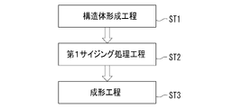
- the rotating member 2 is manufactured through a structure forming step ST1, a first sizing processing step ST2, and a molding step ST3.
- the structure forming step ST1 the CNTs 17 are attached to each of the carbon fibers 11 (raw yarns) of the carbon fiber bundle 12 to form the structure 14.
- the carbon fiber bundle 12 is immersed in the CNT isolated dispersion (hereinafter, simply referred to as the dispersion) in which the CNT 17 is isolated and dispersed, and mechanical energy is applied to the dispersion.
- Isolation and dispersion refers to a state in which CNTs 17 are physically separated one by one and dispersed in a dispersion medium without being entangled, and the proportion of aggregates in which two or more CNTs 17 are aggregated in a bundle is 10%.
- the proportion of the aggregate is 10% or more, the aggregation of the CNT 17 in the dispersion medium is promoted, and the adhesion of the CNT 17 to the carbon fiber 11 is inhibited.
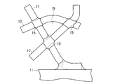
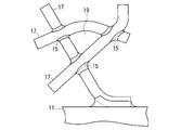
- the attachment device 21 is a traveling mechanism (not shown) for traveling the CNT attachment tank 22, the guide rollers 23 to 26, the ultrasonic generator 27, the carbon fiber bundle 12 at a constant speed, and the like. It is composed.
- the dispersion liquid 28 is housed in the CNT attachment tank 22.
- the ultrasonic generator 27 applies ultrasonic waves to the dispersion liquid 28 in the CNT adhering tank 22 from the lower side of the CNT adhering tank 22.
- a long (for example, about 100 m) carbon fiber bundle 12 in which the structure 14 is not formed is continuously supplied to the attachment device 21.
- the supplied carbon fiber bundle 12 is wound around the guide rollers 23 to 26 in order, and travels at a constant speed by the traveling mechanism.
- the bonding device 21 is supplied with a carbon fiber bundle 12 to which no sizing agent is attached to each carbon fiber 11.
- the sizing agent referred to here is for preventing the above-mentioned carbon fiber 11 from being entangled or the like.
- the carbon fiber bundle 12 is wound around the guide rollers 23 to 26 in an opened state.
- the carbon fiber bundles 12 wound around the guide rollers 23 to 26 are subjected to an appropriate tension to reduce the possibility that the carbon fibers 11 are entangled with each other.
- the winding angle of the carbon fiber bundle 12 around the guide rollers 24 to 26 is preferably smaller (90 ° or less).
- the guide rollers 23 to 26 are all flat rollers. As shown in FIG. 10, the roller length (length in the axial direction) L1 of the guide roller 23 is sufficiently larger than the width WL of the opened carbon fiber bundle 12.
- the guide rollers 24 to 26 are the same as the guide rollers 23, and their roller lengths are sufficiently larger than the width WL of the opened carbon fiber bundle 12.
- the guide rollers 23 to 26 are all the same size, the roller length L1 is 100 mm, and the roller diameter (outer diameter) is 50 mm.
- a plurality of carbon fibers 11 are lined up in the thickness direction (diameter direction of the guide roller).
- the guide rollers 24 and 25 of the guide rollers 23 to 26 are arranged in the CNT attachment tank 22. As a result, between the guide rollers 24 and 25, the carbon fiber bundle 12 runs linearly in the dispersion liquid 28 at a constant depth.
- the traveling speed of the carbon fiber bundle 12 is preferably in the range of 0.5 m / min or more and 100 m / min or less. The higher the traveling speed of the carbon fiber bundle 12, the higher the productivity, and the lower the traveling speed, the more effective the uniform adhesion of the CNTs 17, and the more effective the suppression of the entanglement of the carbon fibers 11. Further, the less the carbon fibers 11 are entangled with each other, the more uniform the adhesion of the CNT 17 to the carbon fibers 11 can be.
- the traveling speed of the carbon fiber bundle 12 is 100 m / min or less, the entanglement of the carbon fibers 11 can be suppressed more effectively and the uniformity of adhesion of the CNTs 17 can be further improved. Further, it is more preferable that the traveling speed of the carbon fiber bundle 12 is within the range of 5 m / min or more and 50 m / min or less.
- the ultrasonic generator 27 applies ultrasonic vibration as mechanical energy to the dispersion liquid 28. This creates a reversible reaction state in which the dispersed state in which the CNTs 17 are dispersed and the aggregated state in which the CNTs 17 are aggregated alternately change in the dispersion liquid 28.
- the CNT 17 adheres to each carbon fiber 11 by van der Waals force when shifting from the dispersed state to the aggregated state.
- the mass of the carbon fiber 11 with respect to the CNT 17 is as large as 100,000 times or more, and the energy for the attached CNT 17 to be desorbed is larger than the energy due to the ultrasonic vibration.
- the CNT 17 once adhered to the carbon fiber 11 is not peeled off from the carbon fiber 11 even by the ultrasonic vibration after the adhesion. Since the masses of the CNTs 17 are extremely small, they alternate between a dispersed state and an aggregated state due to ultrasonic vibration.
- the frequency of ultrasonic vibration applied to the dispersion liquid 28 is preferably 40 kHz or more and 950 kHz or less.
- the frequency is 40 kHz or more, the entanglement of the carbon fibers 11 in the carbon fiber bundle 12 is suppressed. Further, when the frequency is 950 kHz or less, the CNT 17 adheres well to the carbon fiber 11.
- the frequency of ultrasonic vibration is preferably 100 kHz or higher.
- the number of CNTs 17 attached to the carbon fibers 11 is 100,000 times or more, so that the entanglement between the carbon fibers 11 is satisfactorily suppressed and the structure 14 is formed.
- the inventors have found that the uniformity of the thickness of the fiber can be ensured.
- the maximum value of the number of adhered liquids varies depending on the CNT concentration of the dispersion liquid 28, and increases as the CNT concentration of the dispersion liquid 28 increases. However, if the CNT concentration of the dispersion liquid 28 becomes so high that the CNT 17 cannot take a dispersed state when ultrasonic vibration is applied, the CNT 17 cannot be attached to the carbon fiber 11.
- the length of the period during which the carbon fiber bundle 12 is traveling in the dispersion liquid 28, that is, the time during which the carbon fiber bundle 12 is traveling between the guide rollers 24 and 25 (hereinafter referred to as the immersion time) is applied to the dispersion liquid 28.
- the traveling speed of the carbon fiber bundle 12, the distance traveled by the carbon fiber bundle 12 in the dispersion liquid 28 (interval between the guide rollers 24 and 25), and the dispersion so as to be 100,000 times or more the period of the ultrasonic vibration. It is preferable to determine the frequency of the ultrasonic vibration applied to the liquid 28.
- the frequency of ultrasonic vibration is fs (Hz) and the immersion time is Ts (seconds).
- the traveling speed of the carbon fiber bundle 12 may be set to 6 m / min or less.
- the number of adhered CNTs 17 can be substantially maximized if the total immersion time is 100,000 times or more of the cycle of ultrasonic vibration. ..
- a standing wave having a fixed sound pressure (amplitude) distribution is generated in the dispersion liquid 28 in the CNT attachment tank 22 by the ultrasonic vibration applied from the ultrasonic generator 27. ..
- the guide rollers 24 and 25 travel in the depth direction of the guide rollers 24 and 25 so that the carbon fiber bundle 12 travels in the dispersion liquid 28 at a depth where the standing wave node of the ultrasonic vibration, that is, the sound pressure is minimized.
- the position of is adjusted. Therefore, the depth from the liquid surface of the dispersion liquid 28 in which the carbon fiber bundle 12 travels in the dispersion liquid 28 is D, and the wavelength of the standing wave of the ultrasonic vibration generated in the dispersion liquid 28 is ⁇ .
- the wavelength ⁇ of the standing wave can be obtained based on the speed of sound in the dispersion liquid 28 and the frequency of the ultrasonic vibration applied from the ultrasonic generator 27.
- the depth at which the carbon fiber bundle 12 travels in the dispersion liquid 28 may deviate slightly from the node of the standing wave, in which case n ⁇ ⁇ / 2- ⁇ / 8 or more n ⁇ ⁇ / 2 + ⁇ /. It is preferably within the range of 8 or less (n ⁇ ⁇ / 2- ⁇ / 8 ⁇ D ⁇ n ⁇ ⁇ / 2 + ⁇ / 8).
- the thread disorder due to the thread slack of the carbon fiber 11 can be set within an allowable range.
- a long CNT (hereinafter referred to as a material CNT) is added to the dispersion medium, and the material CNT is cut by a homogenizer, a shearing force, an ultrasonic disperser, or the like to obtain a CNT 17 having a desired length. At the same time, it is prepared by making the dispersion of CNT 17 uniform.
- the dispersion medium examples include alcohols such as water, ethanol, methanol and isopropyl alcohol, and organic substances such as toluene, acetone, tetrahydrofuran (THF), methyl ethyl ketone (MEK), hexane, normal hexane, ethyl ether, xylene, methyl acetate and ethyl acetate.
- alcohols such as water, ethanol, methanol and isopropyl alcohol
- organic substances such as toluene, acetone, tetrahydrofuran (THF), methyl ethyl ketone (MEK), hexane, normal hexane, ethyl ether, xylene, methyl acetate and ethyl acetate.
- THF tetrahydrofuran
- MEK methyl ethyl ketone
- hexane normal hexane
- the material CNT that is the source of the curved CNT 17 is a curved CNT.
- material CNTs those having the same diameter of individual material CNTs are preferable.
- the material CNTs are preferably those capable of isolating and dispersing CNTs even if the length of each CNT produced by cutting is large. As a result, a dispersion liquid 28 in which CNT 17 satisfying the above-mentioned length conditions is isolated and dispersed can be easily obtained.
- the composite material 10 of this example as described above, a bent shape is attached as the CNT 17, so that the CNT 17 and the surface of the carbon fiber 11 to which the CNT 17 is attached are attached, or between the attached CNTs 17. Another CNT 17 enters the formed space. As a result, more CNTs 17 adhere to the carbon fibers 11. Further, since the CNT 17 is firmly adhered to the carbon fiber 11 to form the structure 14, the CNT 17 is more difficult to peel off from the carbon fiber 11.
- the rotating member 2 manufactured by using such a composite material 10 is derived from CNT and has higher characteristics.
- the concentration of CNT 17 in the dispersion liquid 28 is preferably in the range of 0.003 wt% or more and 3 wt% or less.
- the concentration of CNT 17 in the dispersion liquid 28 is more preferably 0.005 wt% or more and 0.5 wt% or less.
- the carbon fiber bundle 12 is drawn out from the dispersion liquid 28 and then dried.
- the first sizing agent 15 is applied to the structure 14.
- the first sizing process ST2 performs the first sizing process.
- the first sizing treatment includes a step of applying (contacting) the first sizing treatment liquid to the dried carbon fiber bundle 12, and a step of drying the dried carbon fiber bundle 12.
- the first sizing treatment liquid can be prepared by dissolving the above-mentioned carbodiimide compound in a solvent.
- the solvent for dissolving the carbodiimide compound water, alcohol, ketones, a mixture thereof and the like can be used.
- the first sizing treatment liquid is applied to the carbon fiber bundle 12, the method of immersing the carbon fiber bundle 12 in the liquid tank containing the first sizing treatment liquid, the method of spraying the first sizing treatment liquid onto the carbon fiber bundle 12, and the carbon fiber bundle 12. Any method may be used, such as a method of applying the first sizing treatment liquid.
- the first sizing treatment liquid is in a state of being applied to the surface of the CNT 17 while maintaining the direct contact between the CNTs 17, and the lower the viscosity, the closer to the contact portion between the CNTs 17 and the vicinity of the contact portion between the carbon fibers 11 and the CNT 17. Easy to aggregate.
- the desired amount of the sizing agent mass ratio Rm is obtained by adjusting the amount of the first sizing treatment liquid applied to the carbon fiber bundle 12, the concentration of the carbodiimide compound in the first sizing treatment liquid, and the like. can.
- Drying after the application of the first sizing treatment liquid evaporates the solvent (water in this example) of the first sizing treatment liquid.
- Known drying methods include a method of leaving and drying the carbon fiber bundle 12 to which the first sizing treatment liquid is applied, a method of sending a gas such as air to the carbon fiber bundle 12, and a method of heating the carbon fiber bundle 12. Techniques can be used, and heating may be combined with either leaving drying or sending gas.
- the rotating member 2 is molded by the filament winding method using the composite material 10 that has undergone the first sizing treatment step ST2.
- a plurality of composite materials 10 are fed from a creel (thread feeder) 31 while being adjusted to a predetermined tension, and the fed composite material 10 is fed through a filament applying device 32.
- the yarn is supplied to the winder 33.
- the resin applying device 32 the uncured liquid matrix resin M is applied to the surface of the CNT composite fiber.
- the resin applying device 32 impregnates the structure 14 formed on the surface of the carbon fiber 11 with the matrix resin M.
- a mandrel 34 is rotatably set in the filament winder 33.
- the composite material 10 to which the matrix resin M is applied is wound around the mandrel 34 while applying a predetermined tension to the composite material 10.
- the winding position of the composite material 10 around the mandrel 34 is determined by a head (not shown) provided in the resin applying device 32.
- the resin applying device 32 By reciprocating the resin applying device 32 in the axial direction of the mandrel 34 in synchronization with the rotation of the mandrel 34, the winding position of the composite material 10 with respect to the mandrel 34 is shifted while being wound in the axial direction of the mandrel 34.
- the CNT composite fiber to which the matrix resin M is applied is hooped to the mandrel 34. It is wound tightly around the outer peripheral surface of the mandrel 34 in a direction substantially perpendicular to its axis. Further, by adjusting the winding angle of the composite material 10 with respect to the axial direction of the mandrel 34 to an angle smaller than 90 °, for example, 45 °, the CNT composite fiber to which the matrix resin M is applied is helically wound around the mandrel 34. That is, it is precisely wound around the outer peripheral surface of the mandrel 34 at an angle of 45 ° with respect to its axis.
- the mandrel 34 is removed from the filament winder 33 together with the molded body.
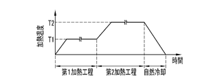
- the molded body is heated together with, for example, the removed mandrel 34, and the matrix resin M applied to the CNT composite fiber is cured.
- the molded body obtained by curing the matrix resin M is removed from the mandrel 34 and cut to a desired width (length in the axial direction) as necessary to form a rotating member 2.
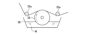
- a touch roll type is used as the resin applying device 32.
- the lower portion of the touch roll 35 is immersed in the uncured liquid matrix resin M stored in the storage tank 36, and the composite material 10 is a pair of guide rollers on the upper outer peripheral surface of the touch roll 35. It is pressed at 35a.
- the touch roll 35 rotates, the stored liquid matrix resin M is applied to the CNT composite fiber via the outer peripheral surface of the touch roll 35.
- the matrix resin M is formed on the carbon fiber 11 on which the composite material 10, that is, the structure 14 is formed. The application amount is adjusted, and the matrix resin M applied to the structure 14 is sufficiently impregnated.
- the matrix resin M is not particularly limited, and various thermosetting resins and thermoplastic resins can be used.
- the thermosetting resin includes epoxy resin, phenol resin, melamine resin, urea resin (urea resin), unsaturated polyester, alkyd resin, thermosetting polyimide, cyanate ester resin, bismaleimide resin, vinyl ester resin and the like. It may be a mixture of these resins.
- the thermoplastic resin is a general-purpose resin such as polyethylene, polypropylene, polyvinyl chloride, polystyrene, acrylonitrile / styrene (AS) resin, acrylonitrile / butadiene / styrene (ABS) resin, methacrylic resin (PMMA, etc.), and thermoplastic epoxy resin.
- Engineering plastics such as resins, polyamides, polyacetals, polyethylene terephthalates, ultrahigh molecular weight polyethylenes, polycarbonates, phenoxy resins, polyphenylene sulfides, polyether ether ketones, polyether ketone ketones, liquid crystal polymers, polytetrafluoroethylene, polyetherimides, polyarylates.
- Super engineering plastics such as polyimide.
- the tensile strength of the rotating member 2 and the fiber volume content (Vf) of the carbon fiber 11 have a positive correlation, and the fiber volume content of the carbon fiber 11 is increased from the viewpoint of increasing the tensile strength.
- the ratio (Vf) is preferably higher, and the fiber volume content of the carbon fiber 11 may be, for example, 75% or more or less than 75%.
- the fiber volume content is preferably less than 75%.
- the fiber volume content of the carbon fiber 11 is 50% or more.
- the fiber volume content of the rotating member 2 is 50% or more and less than 75%.
- the fiber volume content of the carbon fibers 11 in the rotating member 2 is determined by, for example, adjusting the amount of the matrix resin M applied to the composite material 10 by the resin applying device 32 and the tension of the composite material 10 when wound around the mandrel 34. Can be changed.
- the fiber volume content of the carbon fiber 11 of the rotating member 2 can be obtained, for example, by using the formula (3) as follows.
- the value ⁇ is the specific gravity of the rotating member 2
- the value ⁇ f is the specific gravity of the carbon fiber 11
- the value ⁇ m is the specific gravity of the matrix resin M.
- a measuring instrument for example, a high-precision electronic hydrometer SD-200L (manufactured by Alpha Mirage Co., Ltd.)
- ⁇ f of the carbon fiber 11 a value measured by a measuring instrument may be used as in the case of the rotating member 2, or a catalog value (nominal value of the manufacturer of the carbon fiber 11) may be used. Since the specific densities of the CNTs 17 and the first sizing agent 15 adhering to the carbon fibers 11 are very small values with respect to the specific gravities of the carbon fibers 11, the specific gravities of the carbon fibers 11 alone are regarded as the specific ⁇ f . You may consider it.
- the temperature is changed in two steps in the curing step of curing the matrix resin M of the molded product, and the temperature is raised from room temperature to the first heating temperature T1 and the temperature is set to the first heating temperature T1. After that, the temperature is raised to the second heating temperature T2, which is higher than the first heating temperature T1, and the second heating temperature T2 is maintained for a predetermined time. After the second heating temperature T2 is maintained for a predetermined time, the molded body is naturally cooled, and then the molded body is removed from the mandrel 34 to form the rotating member 2.
- the molding is performed in a state where the thermal expansion or contraction of the mandrel 34 due to heating is suppressed in order to reduce the error in the inner diameter dimension of the rotating member 2 to be manufactured.
- This is a step of advancing gelation of the matrix resin M and curing it, with the main purpose of curing the body to a stable shape with little size fluctuation. Therefore, the first heating temperature T1 is set to a temperature that suppresses the thermal expansion of the mandrel 34 to a small value. Further, heating at the first heating temperature T1 is performed until a stable shape of the molded product is obtained, that is, until it can be said that the molded product is cured even if the final strength is not obtained.
- the time for maintaining the first heating temperature T1 is determined as, for example, the time until the storage elastic modulus of the matrix resin M becomes substantially constant. It is preferable to suppress the thermal expansion or contraction of the molded product in the first heating step in order to further reduce the error in the inner diameter dimension of the rotating member 2.
- the first heating temperature T1 is a temperature that suppresses the thermal expansion or contraction of the mandrel 34 to be small, and at the end of the first heating step in order to suppress the thermal expansion or contraction of the molded body.
- the temperature is set to a temperature below the glass transition point of the matrix resin M (a constant temperature below the glass transition point of the matrix resin M that increases during the first heating step). This is also the case in this example.
- the time for maintaining the first heating temperature T1 may be the time until the rate of change (increase rate) of the storage elastic modulus of the matrix resin M starts to decrease, the time until the loss elastic modulus reaches its peak, or the time until it peaks out. .. It should be noted that, for example, using a rheometer, changes in the storage elastic modulus and loss elastic modulus of the matrix resin M with respect to the heating time for each heating temperature can be known, and the time for maintaining the first heating temperature T1 can be determined in advance. can. In addition, the glass transition point of the matrix resin M can be known in advance.
- the molded product is heated at the second heating temperature T2 higher than the first heating temperature T1 to cure the matrix resin M through the first heating step.
- the matrix resin M is a cyanate ester resin
- the first heating temperature T1 is in the range of 100 ° C. or higher and 200 ° C. or lower
- the second heating temperature T2 is in the range of 200 ° C. or higher and 300 ° C. or lower. Is preferable.
- the molded product is heated at the first heating temperature T1 in the first heating step, so that the matrix resin M is cured and a stable shape of the molded product is formed.
- the matrix resin M of the molded product is cured, and the molded product has final strength, elastic modulus, and heat resistance.
- the inner diameter of the rotating member 2 thus produced is almost determined when the stable shape of the molded body is formed in the first heating step, and in the first heating step, heating is performed at the first heating temperature T1. Therefore, the thermal expansion of the mandrel 34 and the thermal expansion or thermal contraction of the matrix resin M are small. As a result, a molded body, that is, a rotating member 2 having a small error in the inner diameter dimension can be obtained.
- the molded body is heated at the second heating temperature T2, so that the mandrel 34 thermally expands more than in the first heating step, and the thermal expansion deforms the molded body having a stable shape.
- the deformation is elastic deformation, it returns to its original state after cooling. Therefore, in the second heating step, the influence of the inner diameter dimension of the molded product is very small.
- the inner diameter dimension when 50 rotating members 2 are actually manufactured by changing the heating temperature stepwise as described above and actually using the carbon steel material S45C for machine structure as the material of the mandrel 34 is 40 mm ⁇ 0. It was .003 mm.
- the inner diameter dimension when 50 rotating members 2 are manufactured by raising the temperature of the molded body from room temperature to the second heating temperature T2 together with the mandrel 34 made of the same material and curing the molded body is 40 mm ⁇ 0.01 mm. That was all. In the former case, the temperature was raised from room temperature to maintain the first heating temperature T1 for 90 minutes, and then the temperature was raised from the first heating temperature T1 to maintain the second heating temperature T2 for 120 minutes.
- the temperature was raised from room temperature to the second heating temperature T2, and the second heating temperature T2 was maintained for 210 minutes.
- the first heating temperature T1 in the former was 145 ° C
- the second heating temperature T2 in the former and the latter was 200 ° C. Therefore, by curing the matrix resin M of the molded product by gradually changing the heating temperature as described above, it becomes easy to control the inner diameter dimension of the rotary member 2 to be manufactured, and the desired inner diameter dimension can be obtained. It can be seen that the rotating member 2 with suppressed error can be manufactured. It should be noted that such a method can be used when the rotating member is manufactured by the filament winding method regardless of the presence or absence of the structure 14, the first sizing agent 15, and the like.
- the heating temperature in the first heating step may be changed stepwise in two or more steps, and each heating temperature may be heated for a predetermined time.
- the carbon fibers 11 are cross-linked with each other by the cross-linked portion CL in which a part of the composite region 18 between the carbon fibers 11 is fixed to each other. It has a cross-linked structure.
- the composite region 18 is a region composed of the structure 14 and the matrix resin M impregnated and cured in the structure 14.
- the composite region 18 has a higher hardness than the cured matrix resin alone, and has high elasticity, that is, a large elastic limit. Further, the composite region 18 has higher wear resistance than the matrix resin.
- the thickness of the structure 14 is preferably at most 300 nm or less from the viewpoint of ensuring quality stability by a uniform thickness and preventing the carbon fiber 11 from falling off.
- the thickness of the structure 14 is preferably in the range of 50 nm or more and 200 nm or less.
- the matrix resin M applied to the carbon fibers 11 is held in the structure 14 in a state of being impregnated. Therefore, in the carbon fiber reinforced molded body such as the rotating member 2, the matrix resin M is hardly biased on the surface of the carbon fiber 11 regardless of the molding method, and the distance between the carbon fibers becomes uniform. Therefore, the load is uniformly transmitted between the carbon fibers mediated by the shearing force of the matrix resin M, and the tensile strength of the rotating member 2 is effectively increased.
- FIG. 16 shows an image of the internal structure of a columnar rod manufactured as a carbon fiber reinforced molded body using a composite material 10 by X-ray CT, which is a pultrusion molding method. It can be confirmed that in the rod produced by using the composite material 10, there is no large bias and voids in the matrix resin M, and the distance between the carbon fibers is almost uniform in the entire rod. On the other hand, as shown in FIG. 17, the internal structure of the rod similarly produced using the carbon fiber (raw yarn) to which the CNT is not attached has a large bias and voids in the matrix resin M. Was confirmed.
- the composite material may be provided with a second sizing agent as a coating agent for covering the surface of the CNT of the structure, in addition to the first sizing agent having a structure derived from carbodiimide.
- the second sizing agent 37 is attached to the CNT 17 so as to cover the surface of the CNT 17 of the structure 14.
- the second sizing agent 37 is made of a cured or uncured product of a reaction-curable resin, a thermosetting resin, or a thermoplastic resin.
- the second sizing agent 37 is applied to the composite material 10 by a second sizing treatment after the first sizing treatment for applying the first sizing agent 15.
- the second sizing treatment can be carried out by a general method, and the opened carbon after the first sizing treatment is added to the second sizing treatment liquid in which the resin (polymer) to be the second sizing agent 37 is dissolved in the dispersion medium.
- the dispersion medium is evaporated and the second sizing agent 37 is cured or semi-cured.
- An emulsion-type second sizing treatment liquid containing a droplet-shaped resin as a second sizing agent can also be used.
- the resin to be the second sizing agent 37 is not particularly limited, and various reaction-curable resins, thermosetting resins, thermoplastic resins and the like can be used.
- the thermosetting resin include epoxy resin, phenol resin, melamine resin, urea resin (urea resin), unsaturated polyester, alkyd resin, thermosetting polyimide, cyanate ester resin, and resin having a reactive group. Be done.
- the thermoplastic resin includes general-purpose resins such as polyethylene, polypropylene, polystyrene, acrylonitrile / styrene (AS) resin, acrylonitrile / butadiene / styrene (ABS) resin, methacrylic resin (PMMA, etc.), vinyl chloride, and thermoplastic epoxy resin. , Polyamitone, Polyacetal, Polyethylene terephthalate, Ultrahigh molecular weight polyethylene, Engineering plastics such as polycarbonate, Polyphenylene sulfide, Polyether ether ketone, Liquid crystal polymer, Polytetrafluoroethylene, Polyetherimide, Polyarylate, Polycarbonate and other super engineering plastics. be able to.
- general-purpose resins such as polyethylene, polypropylene, polystyrene, acrylonitrile / styrene (AS) resin, acrylonitrile / butadiene / styrene (ABS) resin, me
- the second sizing agent 37 covers the surface of the CNT 17 containing the first sizing agent 15. Of such a second sizing agent 37, the portion of the first sizing agent 15 crosslinks with the first sizing agent 15, but the portion without the first sizing agent 15 does not crosslink and thus has viscosity. ing.
- the second sizing agent 37 improves the focusing property of the fiber bundle composed of the plurality of carbon fibers 11 on which the structure 14 is formed. It is preferable that the second sizing agent 37 does not block the void portion 19 of the structure 14, as in the case of the first sizing agent 15.
- the rotating member used in the surface magnet type motor is not limited to this.
- it may be a member fitted to the rotor of a generator having the same structure as the surface magnet type motor, or a rotating member such as a rotary cylinder used in a centrifuge.
- the structure may be such that other members are integrally formed or assembled on the inner circumference or the outer circumference of the rotating member such as a cylinder or a ring. Therefore, a carbon fiber reinforcing layer to be a rotating member may be formed as a part of the member including other members.
- Example 1 the composite material 10 was prepared by the above procedure, a peeling experiment of CNT 17 was conducted, and the effect of the first sizing agent 15 was confirmed.
- the dispersion liquid 28 used in the production of the composite material 10 was prepared using the material CNT having a curved shape as described above.
- FIG. 19 shows an SEM photograph of the material CNT used for preparing the dispersion liquid 28. This material CNT had multiple layers and had a diameter in the range of 3 nm or more and 10 nm or less.
- the material CNT was washed with a 3: 1 mixed acid of sulfuric acid and nitric acid to remove the catalyst residue, and then filtered and dried.
- the material CNT was added to acetone as a dispersion medium of the dispersion liquid 28, and the material CNT was cut using an ultrasonic homogenizer to obtain CNT 17.
- the length of the CNT 17 in the dispersion 28 was 0.2 ⁇ m or more and 5 ⁇ m or less. Further, the CNT 17 in the dispersion liquid 28 could be evaluated as having a bent shape.
- the carbon fiber bundle 12 contains 12,000 carbon fibers 11.
- the diameter of the carbon fiber 11 is about 7 ⁇ m, and the length is about 500 m.
- the carbon fiber bundle 12 Prior to the adhesion of the CNT 17, the carbon fiber bundle 12 had a sizing agent removed from the surface of the carbon fiber 11 to prevent the carbon fiber 11 from being entangled.
- the carbon fiber bundle 12 was wound around the guide rollers 23 to 26 in a state of being opened, and was run in the dispersion liquid 28 in the CNT adhesion tank 22.
- the traveling speed of the carbon fiber bundle 12 was set to 1 m / min, and the dispersion liquid 28 was subjected to ultrasonic vibration having a frequency of 200 kHz by the ultrasonic generator 27.
- the immersion time running between the guide rollers 24 and 25 was 6.25 seconds. This immersion time is 1250000 cycles of ultrasonic vibration applied to the dispersion liquid 28.
- the first sizing treatment was carried out to impart the first sizing agent 15 to the CNTs 17 constituting the structure 14.
- a first sizing treatment liquid in which "carbodilite V-02" (trade name, manufactured by Nisshinbo Chemical Co., Ltd.) was dissolved in water was used as the carbodiimide compound.
- the concentration of the carbodiimide compound in the first sizing treatment liquid was adjusted so that the sizing agent mass ratio Rm was 1.0%.
- the carbon fiber bundle 12 subjected to the first sizing treatment was dried to obtain a composite material 10.
- a plurality of CNTs 17 are uniformly dispersed and adhered to a plurality of carbon fibers 11 (hereinafter referred to as sample fibers) obtained by cutting out a part of the carbon fiber bundle 12 subjected to the first sizing treatment as described above. That was observed by SEM. As a result, it was confirmed that the CNTs 17 were uniformly adhered to the carbon fiber 11 even in a narrow range (locally) in the fiber axis direction and in a wide range to form the structure 14. Further, the structure 14 is formed in a non-woven fabric shape having a three-dimensional mesh structure composed of a large number of CNTs 17, that is, a gap portion 19, and most of the gap portion 19 is not blocked by the first sizing agent 15. confirmed.
- the sample fiber was immersed in a mixed solution of water and a surfactant, and the mixed solution was subjected to ultrasonic vibration from an ultrasonic generator for 10 minutes.
- the length of the carbon fiber 11 immersed in the mixed solution was 1 m
- the concentration of the surfactant in the mixed solution was 0.2% by mass
- the frequency of the ultrasonic vibration applied to the mixed solution was 100 kHz.
- Comparative Example 1 a CNT peeling experiment was conducted on the carbon fibers obtained by performing the first sizing treatment using a sizing treatment liquid in which an epoxy resin was dissolved in acetone instead of the carbodiimide compound.
- the same conditions as above were used except that the sizing treatment liquid was different.
- the concentration of the epoxy resin in the sizing treatment liquid was adjusted so that the sizing agent mass ratio Rm was 1.0%.
- the mixed solution became black and turbid, and when confirmed after the peeling experiment, it was confirmed that 90% or more of the CNTs had fallen off from the carbon fibers.
- the mixed solution was slightly turbid and that the CNT 17 was hardly dropped from the carbon fiber 11. That is, the first sizing agent 15 having a structure derived from carbodiimide strengthens the contact between the CNTs 17 and the CNTs 17 and the carbon fibers 11, and the disintegration of the structure 14 and the peeling of the structure 14 from the carbon fibers 11 are effective. It was found that it was suppressed.
- Example 2 the composite material 10 prepared under the same conditions as in Example 1 was used to prepare a test piece A21 which is a carbon fiber reinforced molded body, and a mode I interlayer fracture toughness test was performed.
- the test piece A21 had a length of 160 mm, a width of 23 mm, and a thickness of 3 mm.
- a prepreg was prepared using the composite material 10 subjected to the first sizing treatment, a plurality of prepregs cut into rectangles (160 mm ⁇ 23 mm) were laminated, and the matrix resin was cured by heating while pressurizing.
- the test piece A21 was produced by allowing the test piece A21 to be produced. Each prepreg was cut so that the longitudinal direction coincided with the fiber axial direction of the carbon fiber 11, and the test piece A21 matched the fiber axial directions of all the carbon fibers 11 with the longitudinal direction thereof.
- the mode I interlayer fracture toughness test was performed on the test piece A21 using an autograph precision universal testing machine AG5-5kNX (manufactured by Shimadzu Corporation) in accordance with JIS K7086.
- a double cantilever interlayer fracture toughness test method DCB method
- the crosshead speed of the testing machine was changed according to the amount of crack growth. Specifically, the crosshead speed up to a crack growth amount of 20 mm was set to 0.5 mm / min. When the crack growth amount exceeded 20 mm, the crosshead speed was set to 1 mm / min.
- the crack growth length is measured from both sides of the test piece A21 using a microscope, and the load and crack opening displacement are measured. GIC) was requested.
- Comparative Example 2 a carbon fiber reinforced molded product using a composite material obtained by performing the first sizing treatment using a sizing treatment liquid in which an epoxy resin is dissolved in acetone instead of the carbodiimide compound is used, and the composite material is used as a reinforcing fiber.
- Test piece B21 and test piece B22 which is a carbon fiber reinforced molded body using carbon fiber (raw yarn) to which CNT is not attached, were prepared, respectively, and a mode I interlayer fracture toughness test was performed. The test piece B22 is not sized. In Comparative Example 2, the conditions were the same as those of the test piece A21 except for the above conditions.
- the mode I interlayer fracture toughness strength GIR of the mode I interlayer fracture toughness value (GIC) at a crack growth amount of 20 mm was 0.425 kJ / m 2 for the test piece A21 of Example 2 and 0 for the test piece B21 of Comparative Example 2. It was 323 kJ / m 2 and the test piece B22 was 0.231 kJ / m 2 . From this result, the test piece (carbon fiber reinforced molded body) A21 of Example 2 had a mode I interlayer fracture toughness strength GIR of about 1.32 times that of the test piece B21 of Comparative Example 2 and that of the test piece B22. It can be seen that the improvement is about 1.84 times.
- Example 3 Solid rods A31 and A32, which are carbon fiber reinforced molded bodies using the composite material 10 produced in the same manner as in Example 1 as reinforced fibers, are produced, and a three-point bending test is performed on these rods A31 and A32. gone.
- a cylindrical molded body having a diameter of about 2.6 mm is directly produced from the composite material 10 and the matrix resin by a pultrusion molding method, and the molded body is centerless polished to have a cross section closer to a perfect circle.
- Rods A31 and A32 having a diameter of about 2.2 mm were produced. Therefore, the rods A31 and A32 have the same axial center direction and the fiber axial direction of the carbon fiber 11.
- a plurality of test pieces having a length of 120 mm are prepared by cutting the rods A31 and A32, respectively, and the test pieces are subjected to 3 according to JIS K7074: 1988 "Bending test method for carbon fiber reinforced plastic".
- a point bending test was performed. The distance between the fulcrums was 80 mm.
- an indenter with a relatively low descent speed hereinafter referred to as a low-speed bending test
- a high-speed one hereinafter referred to as a high-speed bending test
- the descent speed of the indenter was set to 5 mm / sec
- the descent speed of the indenter was set to 1 m / sec and 5 m / sec.
- N breaking load
- Vf fiber volume content
- solid rods B31 and B32 which are carbon fiber reinforced molded bodies using carbon fibers (raw yarn) to which CNTs are not attached, are produced, and these rods B31 and B32 are bent at three points.
- a test was conducted.
- the carbon fibers of the rod B31 are the same as those of the rod A31, and the carbon fibers of the rod B32 are the same as those of the rod A32.
- the rods B31 and B32 were manufactured under the same conditions as the rods A31 and A32 except that carbon fiber was used as the raw yarn. Further, the three-point bending test for the rods B31 and B32 was performed under the same conditions as the rods A31 and A32, and the fracture load (N) was determined.
- the rod A31 had 11% higher fracture strength than the rod B31, and the rod A32 had a 23% higher fracture strength than the rod B32. Further, in the high-speed bending test, the rod A31 had 14% higher fracture strength than the rod B31, and the rod A32 had 11% higher fracture strength than the rod B32.
- Example 4 ring-shaped test pieces A41 and A42, which are carbon fiber reinforced molded bodies using the composite material 10 produced in the same manner as in Example 1, were produced as rotating members, and a NOL ring test (based on ASTM D2290) was performed. rice field. That is, the tensile strength in the circumferential direction was determined using the ring-shaped test pieces A41 and A42 in which the composite material 10 as the fiber base material was wound in parallel in one direction. The ring-shaped test pieces A41 and A42 were produced by using the filament winding method as described above.
- the cylindrical mandrel 34 attached to the filament winder 33 was impregnated with the matrix resin M in the composite material 10 (CNT composite fiber) after the first sizing treatment, and then wound to form a molded body.
- the molded product was heated together with the mandrel 34 to cure the matrix resin M.
- the matrix resin M was cured, the molded product from which the mandrel 34 was removed was cut into a predetermined width to obtain ring-shaped test pieces A41 and A42.
- the matrix resin M was applied to the composite material 10 after the first sizing treatment using a roll coater.
- Trading card T1100 manufactured by Toray Industries, Inc.
- Other production conditions of the composite material 10 were the same as in Example 1.
- the ring-shaped test pieces A41 and A42 had an inner diameter of 35 mm, an outer diameter of 40 mm, and a width of 3 mm.
- the NOL ring test was carried out at a tensile speed of 2 mm / min using a 5582 type universal material testing machine (manufactured by Instron).
- the test results are shown in FIG. In FIG. 21, the horizontal axis is the fiber volume content (Vf), and the vertical axis is an index value showing the relative tensile strength when the theoretical strength when the fiber volume content is 100% is 100. be. Further, the graph of FIG. 21 also shows the theoretical value of the tensile strength for the same fiber volume content as the ring-shaped test pieces A41 and A42.
- ring-shaped test pieces B41 to B44 which are carbon fiber reinforced molded bodies using carbon fiber (raw yarn) to which CNT was not attached, were prepared and subjected to a NOL ring test.
- the carbon fibers of the ring-shaped test pieces B41 to B44 were the same as those of the ring-shaped test pieces A41 and A42, and were produced under the same conditions as the ring-shaped test pieces A41 and A42 except that the carbon fibers were used as the raw yarn. did.
- the test results of the ring-shaped test pieces B41 to B44 of Comparative Example 4 are shown in FIG.
- the ring-shaped test pieces A41 and A42 having the carbon fiber 11 to which the CNT 17 is attached as the reinforcing fiber have higher tensile strength than the ring-shaped test pieces B41 to B44 having the carbon fiber (raw yarn) as the reinforcing fiber. Is improved, and it can be seen that the tensile strength is close to the theoretical value.
- Example 5 the interfacial adhesive strength between the carbon fiber 11 and the matrix resin was evaluated by the fragmentation method. At the same time, the interfacial adhesive strength between the carbon fiber 11 and the matrix resin was evaluated depending on the difference in the sizing agent mass ratio Rm.
- the concentration of the carbodiimide compound in the first sizing treatment liquid is adjusted so that the sizing agent mass ratio Rm is 0.6%, 0.8%, 1.0%, 1.1%, and 1.5%. 10 were prepared respectively.
- the produced composite materials 10 one CNT composite fiber was taken out from the carbon fiber bundle 12, and the test pieces A51 to A55 in which the CNT composite fiber was embedded in the soft epoxy resin were prepared.
- Three test pieces A51 to A55 were prepared for each of a plurality of production lots of the composite material 10.
- As the carbon fiber 11 a trading card T700SC (manufactured by Toray Industries, Inc. was used.
- the production conditions of the other composite material 10 are the same as in Example 1.
- test pieces A51 to A55 For each of the test pieces A51 to A55, a tensile load is applied until the carbon fiber 11 is not cut, and then the length of each cut piece of the carbon fiber 11 at a constant length is measured for each test piece, and the test pieces A51 to A51 to For each of A55, the average length of the cut pieces (cut fiber length) was calculated for each production lot. The measurement result is shown in the graph of FIG.
- a test piece B51 in which one carbon fiber (raw yarn) to which CNT was not attached was embedded in a soft epoxy resin was produced. Similar to the test pieces A51 to A55, a tensile load was applied to the test piece B51, and the average length of the cut pieces (cut fiber length) was obtained for each production lot. The measurement result is shown in the graph of FIG. The conditions for producing the test piece B51 were the same as those of the test pieces A51 to A55 except that the CNTs did not adhere to the carbon fibers.
- the cut fiber length of the test pieces A51 to A55 is shorter than the cut fiber length of the test piece B51 of Comparative Example 5, and the interfacial adhesion strength between the CNT composite fiber and the matrix resin is carbon to which CNT is not adhered. It can be seen that it is higher than that of fiber (raw yarn). Further, it can be seen that the interfacial adhesive strength of the test pieces A51 to A54 in the range of 0.6% or more and 1.1% or less of the sizing agent mass ratio Rm with respect to the test piece B51 is remarkably high.
- the first sizing agent 15 on the surface of the structure 14 is a field emission type.
- the state observed by the scanning electron microscope (FE-SEM) is shown in FIGS. 23 to 25.
- the structure 14 having a sizing agent mass ratio Rm of 0.8% and 1.1% the void portion 19 formed by the CNT 17 was not blocked by the first sizing agent 15, but the sizing agent mass ratio Rm was 1. It was confirmed that in the 5% structure 14, many voids 19 were blocked by the first sizing agent 15.
- Example 6 In Example 6, using the composite material 10 as a reinforcing fiber, a plurality of ring-shaped test pieces A6 as rotating members 2 having different fiber volume contents (Vf) of carbon fibers were produced, and the tensile strength of each was tested by NOL ring test. Measured according to (ASTM D2290 compliant). Further, as Comparative Example 6, a plurality of ring-shaped test pieces B6 having different fiber volume contents (Vf) of the carbon fibers were prepared using the raw yarn (carbon fiber) as the reinforcing fiber, and the tensile strength of each was measured in the same manner. ..
- Example 6 The NOL ring test of Example 6 and Comparative Example 6 was carried out using the above-mentioned 5582 type universal material tester at a tensile speed of 2 mm / min.
- the ring-shaped test pieces A6 and B6 were produced in the same manner as in Example 4.
- Trading Card T1100SC-12000 manufactured by Toray Industries, Inc. was used as the carbon fiber 11 for both the ring-shaped test pieces A6 and B6.
- ⁇ is a plot of each measurement result of Example 6, and ⁇ is a plot of each measurement result of Comparative Example 6.
- the horizontal axis is the fiber volume content (Vf) of the carbon fiber in the ring-shaped test piece, and the vertical axis is the tensile strength (index value).
- the solid line is an approximate straight line showing the relationship between the fiber volume content and the tensile strength (index value) obtained by the minimum self-squared method based on the measured value of Example 6, and the broken line is the measured value of Comparative Example 6. Based on this, it is an approximate straight line showing the relationship between the fiber volume content and the tensile strength (index value) obtained in the same manner as in Example 6.
- the tensile strength (index value) is the tensile strength when the fiber volume content of the reinforcing fiber obtained from the relationship (approximate straight line) between the fiber volume content in Comparative Example 6 and the tensile strength (index value) is 70%. It is a value indicating the relative tensile strength when it is set to "100". Further, FIG. 27 shows an enlarged region of FIG. 26 having a fiber volume content of 60% or more and a tensile strength (index value) of 90 or more.
- each ring-shaped test piece A6 is 70% or more (less than 75%) in which the fiber volume content is relatively low in the range of 60% or more and less than 70%, and the fiber volume content is high in the range of 70% or more (less than 70%). Also in the range of, it is plotted above the approximate straight line showing the relationship between the fiber volume content and the tensile strength (index value) of Comparative Example 6.
- each ring-shaped test piece A6 having a CNT composite fiber as a reinforcing fiber has a higher tensile strength than a ring-shaped test piece having a raw yarn of carbon fiber having the same fiber volume content as a reinforcing fiber.
- the tensile strength of the ring-shaped test piece using the composite material 10 as the reinforcing fiber as in Example 6 is such that the raw yarn is used as the reinforcing fiber as in Comparative Example 6.
- the value is about 10% higher than the tensile strength of the ring-shaped test piece.
- the fiber volume content for obtaining the same tensile strength is about 10% smaller when the composite material 10 is made of reinforced fiber than when the raw yarn is made of reinforced fiber. From the approximate straight line, the tensile strength when the fiber volume content of the ring-shaped test piece using the composite material 10 as the reinforcing fiber is 74% is when the fiber volume content of the ring-shaped test piece using the raw yarn as the reinforcing fiber is 81%. Corresponds to the value of tensile strength of.
- the carbon fiber reinforced molded body becomes brittle due to the decrease in the amount of matrix resin, so that there is a limit to the increase in the fiber volume content for improving the tensile strength.
- the composite material 10 as the reinforcing fiber of the rotating member 2
- higher tensile strength can be obtained even with a relatively small fiber volume content as compared with the one using the raw yarn as the reinforcing fiber, so that high tensile strength can be obtained. Both strength and high brittle resistance can be achieved.
- Example 7 As Example 7, the fracture state was evaluated for a plurality of ring-shaped test pieces having different fiber volume contents (Vf).
- the plurality of ring-shaped test pieces evaluated include each ring-shaped test piece A6 for which the tensile strength was measured in Example 6 described above.
- the evaluation of the destructive state was performed as follows. First, a plurality of ring-shaped test pieces A6 to be evaluated were divided into a first group having a fiber volume content of 60% or more and less than 70% and a second group having a fiber volume content of 70% or more. Then, it was pulled at a tensile speed of 2 mm / min using a 5582 type universal material tester, and the fracture state of each fractured ring test piece was examined.
- the rupture state of the ring test piece can be roughly classified into two types, the fault rupture mode and the interlayer rupture mode.
- Each group was classified into a fault rupture mode and an interlayer rupture mode.
- the percentage of the number of pieces classified into each destruction mode in each group was calculated.
- the calculated ratios are shown in Table 1 as evaluation results.
- Comparative Example 7 a plurality of ring-shaped test pieces in which the raw yarn was used as a reinforcing fiber and the fiber volume content (Vf) of the carbon fiber was different were evaluated in the same manner as in Example 7.
- the plurality of ring-shaped test pieces evaluated include each ring-shaped test piece B6 for which the tensile strength was measured in Comparative Example 6 described above. The evaluation results are shown in Table 2.
- the fault rupture mode is a rupture mode in which each of a plurality of carbon fibers constituting the ring-shaped test piece is cut.
- this tomographic rupture mode as a result of analysis of the X-ray CT image, cracks occur diagonally across each fiber layer, leading to rupture, and peeling does not occur in all or most of each fiber layer after rupture. confirmed.
- the interlayer fracture mode is a fracture mode in which cracks are formed in the circumferential direction to form a collapsed shape.
- the X-ray CT image in the interlayer fracture mode it was confirmed by the X-ray CT image that the ring-shaped test piece was separated between the fiber layers and the fracture occurred. It was confirmed that the peeling between the layers of each fiber after the fracture occurred in almost all layers.
- Example 7 the second group (70% ⁇ Vf) having a relatively high tensile strength is all in the fault rupture mode, and the first group (60% ⁇ Vf ⁇ 70%) having a relatively small tensile strength. Then, all are in the interlayer destruction mode.
- the second group was all in the fault rupture mode as in Comparative Example 7, but in the first group, 21% was in the interlayer rupture mode and 79% was in the fault rupture mode. .. This is because, in Example 7, even when the fiber volume content is 60% or more and less than 70%, the interfacial adhesive strength between the matrix resin M and the carbon fiber 11 is substantially improved by the formation of the composite region 18, and the layers are layered. It is probable that the peeling of the fibers is less likely to occur, and the number of interfacial fracture modes is reduced as compared with Comparative Example 7.
- Example 8 a part of the ring-shaped test piece A6 broken in the tensile test of Example 6 was cut out and used as an observation sample for observing the cut surface. The cut surface of this observation sample was polished and observed with a scanning electron microscope (SEM, Scanning Electron Microscope) and a field-emission scanning electron microscope (FE-SEM, Field-Emission Scanning Electron Microscope). Further, in Comparative Example 8, a part of the ring-shaped test piece B6 broken in the tensile test of Comparative Example 6 was cut out to prepare an observation sample, and the observation was carried out in the same manner as in Example 8. 30 is an SEM photograph of Example 8, FIG. 31 is an SEM photograph of Comparative Example 8, FIG.
- FIG. 32 is an FE-SEM photograph of Example 8
- FIG. 33 is an FE-SEM photograph of Comparative Example 8.
- the ring-shaped test piece A6 obtained by cutting out the observation sample has a fiber volume content of 72.2%
- the ring-shaped test piece B6 has a fiber volume content of 72.5%.
- the ring-shaped test piece A6 has a uniform film thickness so that the composite region 18 having a thickness of about 0.1 ⁇ m covers the surface of the carbon fiber 11 at the interface between the carbon fiber 11 and the matrix resin M.
- the matrix resin M enters the voids in the three-dimensional mesh-like structure 14 in which a plurality of CNTs 17 are entwined with each other like a non-woven fabric, and the matrix resin M becomes a three-dimensional network and becomes mutual. It entered as a network structure, and it was observed that CNT17 and the matrix resin M formed a mutual network structure at the nano level.
- the composite region 18 was compressed and the thickness was 0.01 ⁇ m or less in the region where the adjacent carbon fibers 11 were close to each other in the close-packed portion. It can be seen that the composite regions 18 on the adjacent carbon fibers 11 are fixed and integrated with each other, and the above-mentioned carbon fibers 11 form a crosslinked structure.
Abstract
Description
図3において、複合素材10は、複数の連続した炭素繊維11をまとめた炭素繊維束12を含む。各炭素繊維11の表面には、それぞれ構造体14が形成されており、構造体14には、第1サイジング剤15(図4参照)が付与されている。 [Composite material]
In FIG. 3, the


CNT質量比Rcは、それを求めようとする測定部位について1m程度に炭素繊維束12(例えば12000本程度のCNT複合繊維)を切り出して測定試料として、下記のようにして求める。
(1)CNT17の分散媒となる液(以下、測定液という)に測定試料を投入する。測定液としては、例えばNMP(N-メチル-2-ピロリドン、CAS登録番号:872-50-4)に分散剤を入れたものを用いる。分散剤は、CNT17を炭素繊維11に再付着させないために測定液に添加しているが、添加しなくてもよい。測定液の量は、例えば測定試料10gに対して100mlである。
(2)測定試料を投入する前の測定液の質量と、投入後の測定試料を含む測定液の質量との差分を計測し、これを測定試料の質量、すなわち炭素繊維11のCF質量Waとその炭素繊維11に付着しているCNT17のCNT質量Wbとの和(Wa+Wb)とする。
(3)測定試料を含む測定液を加熱して、炭素繊維11からそれに付着しているCNT17を完全に分離し、CNT17を測定液中に分散する。
(4)吸光光度計を用いて,CNT17が分散している測定液の吸光度(透過率)を測定する。吸光光度計による測定結果と、予め作成しておいた検量線とから測定液中のCNT17の濃度(以下、CNT濃度という)を求める。CNT濃度は、その値をC、測定液の質量をW1、この測定液に含まれるCNT17の質量をW2としたときに、「C=W2/(W1+W2)」で与えられる質量パーセント濃度である。
(5)得られるCNT濃度と測定試料を投入する前の測定液の質量とから測定液中のCNT17のCNT質量Wbを求める。
(6)(2)で求められるCF質量WaとCNT質量Wbとの和(Wa+Wb)と、CNT17のCNT質量(Wb)とから、CNT質量比Rc(=Wb/(Wa+Wb))を算出する。 [Measurement of CNT mass ratio]
The CNT mass ratio Rc is obtained by cutting out a carbon fiber bundle 12 (for example, about 12,000 CNT composite fibers) to about 1 m at the measurement site to be obtained and using it as a measurement sample as follows.
(1) The measurement sample is put into a liquid (hereinafter referred to as a measurement liquid) which is a dispersion medium of CNT17. As the measuring solution, for example, NMP (N-methyl-2-pyrrolidone, CAS Registry Number: 872-50-4) containing a dispersant is used. The dispersant is added to the measuring solution so as not to reattach the
(2) The difference between the mass of the measurement liquid before charging the measurement sample and the mass of the measurement liquid including the measurement sample after charging is measured, and this is referred to as the mass of the measurement sample, that is, the CF mass Wa of the
(3) The measurement liquid containing the measurement sample is heated to completely separate the
(4) Using an absorptiometer, measure the absorbance (transmittance) of the measuring solution in which
(5) The CNT mass Wb of the
(6) The CNT mass ratio Rc (= Wb / (Wa + Wb)) is calculated from the sum (Wa + Wb) of the CF mass Wa and the CNT mass Wb obtained in (2) and the CNT mass (Wb) of the
サイジング剤質量比率Rmの測定では、各炭素繊維11の構造体14に第1サイジング剤15を付着させて作成した炭素繊維束12から、例えば3本のCNT複合繊維を切り出して測定試料として、下記のようにして求める。測定試料として切り出すCNT複合繊維の長さは例えば5mとする。なお、測定試料とするCNT複合繊維の本数、長さは、これらに限定されない。 [Measurement of sizing agent mass ratio]
In the measurement of the sizing agent mass ratio Rm, for example, three CNT composite fibers are cut out from the
(2)測定試料を投入する前の測定液の質量と、投入後の測定試料を含む測定液の質量との差分を計測し、これを測定試料の質量、すなわち炭素繊維11のCF質量Wa、炭素繊維11に付着しているCNT17のCNT質量Wb及びCNT17に付着している第1サイジング剤15のサイズ剤質量Wcとの和(Wa+Wb+Wc)とする。
(3)測定試料を含む測定液加熱して、炭素繊維11からそれに付着しているCNT17を完全に分離し、CNT17を測定液中に分散する。
(4)CNT質量比Rcを測定する場合と同様に、吸光光度計を用いてCNT17が分散している測定液の吸光度を測定し、その吸光度と、予め作成しておいた検量線とから測定液中のCNT17のCNT濃度を求める。得られるCNT濃度と測定試料を投入する前の測定液の質量とから測定液中のCNT質量Wbを求める。
(5)使用している炭素繊維11(原糸)のカタログ値からCF質量Waを特定する。
(6)測定試料の質量(Wa+Wb+Wc)から、(5)で得られるCF質量Wa及び(4)得られるCNT質量Wbを減算した差を求め、これを測定試料に付与されていた第1サイズ剤のサイズ剤質量Wcとする。
(7)(5)で得られるCF質量Waと、(6)で得られるサイズ剤質量Wcとからサイジング剤質量比率Rm(=(Wc/Wa)×100%)を算出する。 (1) Add the measurement sample to the measurement liquid of CNT17. The conditions of the measuring liquid and the dispersion medium are the same as those for measuring the CNT mass ratio Rc described above.
(2) The difference between the mass of the measurement liquid before charging the measurement sample and the mass of the measurement liquid including the measurement sample after charging is measured, and this is measured as the mass of the measurement sample, that is, the CF mass Wa of the
(3) The measuring solution containing the measurement sample is heated to completely separate the
(4) Similar to the case of measuring the CNT mass ratio Rc, the absorbance of the measuring solution in which the
(5) The CF mass Wa is specified from the catalog value of the carbon fiber 11 (raw yarn) used.
(6) The difference obtained by subtracting the CF mass Wa obtained in (5) and the CNT mass Wb obtained in (4) from the mass (Wa + Wb + Wc) of the measurement sample was obtained, and this was applied to the measurement sample as the first size agent. The mass of the sizing agent is Wc.
(7) The sizing agent mass ratio Rm (= (Wc / Wa) × 100%) is calculated from the CF mass Wa obtained in (5) and the sizing agent mass Wc obtained in (6).

実施例1では、上記手順により複合素材10を作製し、CNT17の剥離実験を行い、第1サイジング剤15の効果を確認した。複合素材10の作製の際に用いた分散液28は、上述のように曲がった形状を有する材料CNTを用いて調製した。図19に分散液28の調製に用いた材料CNTのSEM写真を示す。この材料CNTは、多層であり、直径が3nm以上10nm以下の範囲であった。材料CNTは、硫酸と硝酸の3:1混酸を用いて洗浄して触媒残渣を除去した後、濾過乾燥した。分散液28の分散媒としてのアセトンに材料CNTを加え、超音波ホモジナイザーを用いて材料CNTを切断し、CNT17とした。分散液28中のCNT17の長さは、0.2μm以上5μm以下であった。また、分散液28中のCNT17は、曲がった形状と評価できるものであった。分散液28のCNT17の濃度は、0.12wt%(=1200wt ppm)とした。分散液28には、分散剤や接着剤を添加しなかった。 <Example 1>
In Example 1, the
実施例2では、実施例1と同じ条件で作製した複合素材10を用いて、炭素繊維強化成形体である試験片A21を作製し、モードI層間破壊靱性試験を行った。試験片A21は、長さ160mmとし、幅23mm、厚さ3mmとなるように作製した。実施例2では、第1サイジング処理を施した複合素材10を用いてプリプレグを作製し、長方形(160mm×23mm)に切断した複数枚のプリプレグを積層し、加圧しながら加熱してマトリックス樹脂を硬化させることで試験片A21を作製した。各プリプレグは、長手方向が炭素繊維11の繊維軸方向と一致するように切断し、試験片A21は、その長手方向に全ての炭素繊維11の繊維軸方向を一致させた。 <Example 2>
In Example 2, the
実施例3では、実施例1と同様に作製した複合素材10を強化繊維とした炭素繊維強化成形体である中実のロッドA31、A32を作製し、これらロッドA31、A32について3点曲げ試験を行った。実施例3では、引抜成形法によって複合素材10とマトリックス樹脂とから直接に直径約2.6mmの円柱状の成形体を作製し、この成形体にセンタレス研磨を行って断面がより真円に近い直径約2.2mmのロッドA31、A32を作製した。したがって、ロッドA31、A32は、その軸心方向と炭素繊維11の繊維軸方向が一致する。なお、ロッドA31の炭素繊維11(原糸)としては、トレカT700SC(東レ株式会社製)を、ロッドA32の炭素繊維11(原糸)としては、トレカT800SC(東レ株式会社製)をそれぞれ用いた。ロッドA31、A32の、他の作製条件は、実施例1と同じにした。 <Example 3>
In Example 3, solid rods A31 and A32, which are carbon fiber reinforced molded bodies using the
実施例4では、実施例1と同様に作製した複合素材10を用いた炭素繊維強化成形体であるリング状試験片A41、A42を回転部材として作製し、NOLリング試験(ASTM D2290準拠)を行った。すなわち、繊維基材としての複合素材10を一方向に平行巻きしたリング状試験片A41、A42を用いて円周方向の引張強度を求めた。リング状試験片A41、A42は、上述のように、フィラメントワインディング法を用いて作製した。すなわち、フィラメントワインダ33に装着した円筒状のマンドレル34に、第1サイジング処理後の複合素材10(CNT複合繊維)にマトリックス樹脂Mを含浸させてから巻き付けて成形体を形成した。成形体は、マンドレル34とともに加熱してマトリックス樹脂Mを硬化させた。マトリックス樹脂Mの硬化後、マンドレル34を抜いた成形体を所定の幅に切断してリング状試験片A41、A42とした。マトリックス樹脂Mは、ロールコータを用いて第1サイジング処理後の複合素材10に塗布した。炭素繊維11(原糸)としては、トレカT1100(東レ株式会社製)を用いた。複合素材10の他の作製条件は、実施例1と同じにした。 <Example 4>
In Example 4, ring-shaped test pieces A41 and A42, which are carbon fiber reinforced molded bodies using the
実施例5では、フラグメンテーション法により炭素繊維11とマトリックス樹脂との界面接着強度を評価した。あわせて、サイジング剤質量比率Rmの違いによる炭素繊維11とマトリックス樹脂との界面接着強度を評価した。 [Example 5]
In Example 5, the interfacial adhesive strength between the
実施例6では、複合素材10を強化繊維として、炭素繊維の繊維体積含有率(Vf)が異なる回転部材2としての複数のリング状試験片A6を作製し、それぞれの引張強度を、NOLリング試験(ASTM D2290準拠)により測定した。また、比較例6として、原糸(炭素繊維)を強化繊維として、炭素繊維の繊維体積含有率(Vf)が異なる複数のリング状試験片B6を作製し、それぞれの引張強度を同様に測定した。実施例6、比較例6のNOLリング試験は、いずれも前述の5582型万能材料試験機を用い、引張速度2mm/minとして行った。なお、リング状試験片A6、B6は、実施例4と同様に作製した。ただし、リング状試験片A6、B6のいずれにも、炭素繊維11としてトレカT1100SC-12000(東レ株式会社製)を用いた。 [Example 6]
In Example 6, using the
実施例7として、繊維体積含有率(Vf)が異なる複数のリング状試験片について、破壊状態を評価した。評価した複数のリング状試験片は、上述の実施例6で引張強度の測定を実施した各リング状試験片A6を含んでいる。破壊状態の評価は、以下のように行った。まず、評価対象の複数のリング状試験片A6を、繊維体積含有率60%以上70%未満の第1グループと、70%以上の第2グループとにグループ分けした。そして、5582型万能材料試験機を用いて2mm/minの引張速度で引っ張り、破壊した各リング試験片の破壊状態を調べた。リング試験片の破壊状態は、断層破壊モードと層間破壊モードとの2種類に概ね分類できることがわかった。グループ毎に断層破壊モードと層間破壊モードとに分類した。各グループにおいて各破壊モードに分類された個数の割合を百分率で求めた。求めた割合は、評価結果として表1に示す。また、比較例7として、原糸を強化繊維とし、炭素繊維の繊維体積含有率(Vf)が異なる複数のリング状試験片について、実施例7と同様に破壊状態を評価した。評価した複数のリング状試験片は、上述の比較例6で引張強度の測定を実施した各リング状試験片B6を含んでいる。この評価結果を表2に示す。 [Example 7]
As Example 7, the fracture state was evaluated for a plurality of ring-shaped test pieces having different fiber volume contents (Vf). The plurality of ring-shaped test pieces evaluated include each ring-shaped test piece A6 for which the tensile strength was measured in Example 6 described above. The evaluation of the destructive state was performed as follows. First, a plurality of ring-shaped test pieces A6 to be evaluated were divided into a first group having a fiber volume content of 60% or more and less than 70% and a second group having a fiber volume content of 70% or more. Then, it was pulled at a tensile speed of 2 mm / min using a 5582 type universal material tester, and the fracture state of each fractured ring test piece was examined. It was found that the rupture state of the ring test piece can be roughly classified into two types, the fault rupture mode and the interlayer rupture mode. Each group was classified into a fault rupture mode and an interlayer rupture mode. The percentage of the number of pieces classified into each destruction mode in each group was calculated. The calculated ratios are shown in Table 1 as evaluation results. Further, as Comparative Example 7, a plurality of ring-shaped test pieces in which the raw yarn was used as a reinforcing fiber and the fiber volume content (Vf) of the carbon fiber was different were evaluated in the same manner as in Example 7. The plurality of ring-shaped test pieces evaluated include each ring-shaped test piece B6 for which the tensile strength was measured in Comparative Example 6 described above. The evaluation results are shown in Table 2.


実施例8では、実施例6の引張試験にて破断したリング状試験片A6の一部を切り出して切断面を観察するための観察サンプルとした。この観察サンプルの切断面を研磨し、走査電子顕微鏡(SEM、Scanning Electron Microscope)と、電界放出型走査電子顕微鏡(FE-SEM、Field-Emission Scanning Electron Microscope)とのそれぞれで観察した。また、比較例8では、比較例6の引張試験にて破断したリング状試験片B6の一部を切り出して観察サンプルをつくり、実施例8と同様に観察した。図30は実施例8のSEM写真、図31は比較例8のSEM写真、図32は実施例8のFE-SEM写真、図33は比較例8のFE-SEM写真である。なお、観察サンプルを切り出したリング状試験片A6は72.2%の繊維体積含有率、リング状試験片B6は72.5%の繊維体積含有率のものである。 [Example 8]
In Example 8, a part of the ring-shaped test piece A6 broken in the tensile test of Example 6 was cut out and used as an observation sample for observing the cut surface. The cut surface of this observation sample was polished and observed with a scanning electron microscope (SEM, Scanning Electron Microscope) and a field-emission scanning electron microscope (FE-SEM, Field-Emission Scanning Electron Microscope). Further, in Comparative Example 8, a part of the ring-shaped test piece B6 broken in the tensile test of Comparative Example 6 was cut out to prepare an observation sample, and the observation was carried out in the same manner as in Example 8. 30 is an SEM photograph of Example 8, FIG. 31 is an SEM photograph of Comparative Example 8, FIG. 32 is an FE-SEM photograph of Example 8, and FIG. 33 is an FE-SEM photograph of Comparative Example 8. The ring-shaped test piece A6 obtained by cutting out the observation sample has a fiber volume content of 72.2%, and the ring-shaped test piece B6 has a fiber volume content of 72.5%.
3 表面磁石型電動機
4 ロータ
10 複合素材
11 炭素繊維
14 構造体
15 第1サイジング剤
17 カーボンナノチューブ
37 第2サイジング剤
M マトリックス樹脂
2 Rotating
Claims (8)
- 周方向に沿って回転する回転部材において、
周方向に巻いた炭素繊維と、
前記炭素繊維を包埋するマトリックス樹脂と、
屈曲部を有する曲がった形状の複数のカーボンナノチューブで構成され、前記カーボンナノチューブ同士が直接接触した接触部を有するネットワーク構造を形成し、前記炭素繊維の表面に設けられた構造体と
を備えることを特徴とする回転部材。 In a rotating member that rotates along the circumferential direction,
Carbon fiber wound in the circumferential direction and
The matrix resin that embeds the carbon fiber and
It is composed of a plurality of curved carbon nanotubes having a bent portion, forms a network structure having contact portions in which the carbon nanotubes are in direct contact with each other, and is provided with a structure provided on the surface of the carbon fibers. Characterized rotating member. - 前記構造体は、厚さが50nm以上200nm以下の範囲内であることを特徴とする請求項1に記載の回転部材。 The rotating member according to claim 1, wherein the structure has a thickness in the range of 50 nm or more and 200 nm or less.
- 前記炭素繊維の繊維体積含有率が75%未満であることを特徴とする請求項1または2に記載の回転部材。 The rotating member according to claim 1 or 2, wherein the carbon fiber has a fiber volume content of less than 75%.
- 屈曲部を有する曲がった形状のカーボンナノチューブが分散されるとともに超音波振動を印加した分散液に炭素繊維を浸漬し、前記炭素繊維に複数の前記カーボンナノチューブを付着させて、前記カーボンナノチューブ同士が直接接触した接触部を有するネットワーク構造を備える構造体を前記炭素繊維の表面に形成する構造体形成工程と、
前記構造体が形成された前記炭素繊維にマトリックス樹脂を塗布し、前記マトリックス樹脂を塗布した前記炭素繊維をマンドレルに巻回し、前記マトリックス樹脂を硬化させた後に前記マンドレルを引き抜く成形工程と
を有することを特徴とする回転部材の製造方法。 The curved carbon nanotubes having a bent portion are dispersed, and the carbon fibers are immersed in a dispersion liquid to which ultrasonic vibration is applied, and the plurality of the carbon nanotubes are attached to the carbon fibers so that the carbon nanotubes are directly connected to each other. A structure forming step of forming a structure having a network structure having contacted contact portions on the surface of the carbon fiber, and
It has a molding step of applying a matrix resin to the carbon fibers on which the structure is formed, winding the carbon fibers coated with the matrix resin around a mandrel, curing the matrix resin, and then pulling out the mandrel. A method for manufacturing a rotating member. - 前記構造体形成工程後に、カルボジイミド基を有するカルボジイミド化合物を溶解した第1サイジング処理液に前記炭素繊維を接触させ、直接接触した前記カーボンナノチューブ同士を架橋する第1サイジング剤を付与する第1サイジング処理工程を有することを特徴とする請求項4に記載の回転部材の製造方法。 After the structure forming step, the carbon fibers are brought into contact with the first sizing treatment liquid in which the carbodiimide compound having a carbodiimide group is dissolved, and the first sizing treatment for imparting a first sizing agent for cross-linking the directly contacted carbon nanotubes with each other. The method for manufacturing a rotating member according to claim 4, wherein the rotary member has a step.
- 前記第1サイジング処理工程は、前記第1サイジング剤の質量を前記炭素繊維の質量に対して0.6%以上1.1%以下の範囲内で付与することを特徴とする請求項5に記載の回転部材の製造方法。 The fifth aspect of claim 5, wherein the first sizing treatment step imparts the mass of the first sizing agent within the range of 0.6% or more and 1.1% or less with respect to the mass of the carbon fibers. Manufacturing method of rotating members.
- 前記構造体形成工程は、厚さが50nm以上200nm以下の範囲内の前記構造体を形成することを特徴とする請求項5または6に記載の回転部材の製造方法。 The method for manufacturing a rotating member according to claim 5 or 6, wherein the structure forming step forms the structure having a thickness within a range of 50 nm or more and 200 nm or less.
- 前記成形工程は、回転部材における炭素繊維の繊維体積含有率が75%未満となるように前記マトリックス樹脂を塗布した前記炭素繊維をマンドレルに巻回することを特徴とする請求項4ないし7のいずれか1項に記載の回転部材の製造方法。
The molding step is any of claims 4 to 7, wherein the carbon fiber coated with the matrix resin is wound around a mandrel so that the fiber volume content of the carbon fiber in the rotating member is less than 75%. The method for manufacturing a rotating member according to item 1.
Priority Applications (5)
| Application Number | Priority Date | Filing Date | Title |
|---|---|---|---|
| JP2022565511A JP7337289B2 (en) | 2020-11-30 | 2021-11-30 | Rotating member and manufacturing method thereof |
| EP21898196.7A EP4254748A1 (en) | 2020-11-30 | 2021-11-30 | Rotary member and method for manufacturing same |
| US18/039,357 US11958948B2 (en) | 2020-11-30 | 2021-11-30 | Rotary member and method for manufacturing same |
| CN202180079985.XA CN116670983A (en) | 2020-11-30 | 2021-11-30 | Rotary member and method for manufacturing same |
| KR1020237021661A KR20230110794A (en) | 2020-11-30 | 2021-11-30 | Rotating member and manufacturing method thereof |
Applications Claiming Priority (2)
| Application Number | Priority Date | Filing Date | Title |
|---|---|---|---|
| JP2020-199243 | 2020-11-30 | ||
| JP2020199243 | 2020-11-30 |
Publications (1)
| Publication Number | Publication Date |
|---|---|
| WO2022114225A1 true WO2022114225A1 (en) | 2022-06-02 |
Family
ID=81755652
Family Applications (1)
| Application Number | Title | Priority Date | Filing Date |
|---|---|---|---|
| PCT/JP2021/043891 WO2022114225A1 (en) | 2020-11-30 | 2021-11-30 | Rotary member and method for manufacturing same |
Country Status (7)
| Country | Link |
|---|---|
| US (1) | US11958948B2 (en) |
| EP (1) | EP4254748A1 (en) |
| JP (1) | JP7337289B2 (en) |
| KR (1) | KR20230110794A (en) |
| CN (1) | CN116670983A (en) |
| TW (1) | TW202236777A (en) |
| WO (1) | WO2022114225A1 (en) |
Cited By (2)
| Publication number | Priority date | Publication date | Assignee | Title |
|---|---|---|---|---|
| JP7382460B1 (en) | 2022-07-14 | 2023-11-16 | ニッタ株式会社 | Injection molded product and method for manufacturing the same, method for manufacturing composite fiber, CNT-adhered carbon fiber and method for manufacturing the same, and method for manufacturing carbon fiber composite material |
| WO2024042312A1 (en) * | 2022-08-22 | 2024-02-29 | Victrex Manufacturing Limited | Motor with polymeric material rotor and/or stator sleeve |
Citations (5)
| Publication number | Priority date | Publication date | Assignee | Title |
|---|---|---|---|---|
| JP2007238753A (en) | 2006-03-08 | 2007-09-20 | Atomix Co Ltd | Curing agent for aqueous resin and coating material using the same |
| WO2018043046A1 (en) * | 2016-08-31 | 2018-03-08 | コニカミノルタ株式会社 | Substrate with functional fine line and method for forming functional fine line |
| JP2018043521A (en) * | 2017-11-21 | 2018-03-22 | グンゼ株式会社 | Coating member of rotor of magnet type motor |
| WO2018151009A1 (en) * | 2017-02-14 | 2018-08-23 | ニッタ株式会社 | Shaft and frame used for badminton racket, tennis racket, golf club, snowboard, or bicycle |
| WO2020188006A1 (en) * | 2019-03-20 | 2020-09-24 | Safran Electrical & Power | Improved method for manufacturing a rotor |
Family Cites Families (3)
| Publication number | Priority date | Publication date | Assignee | Title |
|---|---|---|---|---|
| JP3813532B2 (en) | 2002-04-19 | 2006-08-23 | 株式会社ジェイテクト | Surface magnet affixing type motor and its assembling method |
| JP5026208B2 (en) | 2007-09-27 | 2012-09-12 | 富士フイルム株式会社 | Carbon nanotube layer-containing structure and manufacturing method thereof |
| KR102337052B1 (en) * | 2013-04-24 | 2021-12-07 | 니타 가부시키가이샤 | Composite material and molded article |
-
2021
- 2021-11-30 CN CN202180079985.XA patent/CN116670983A/en active Pending
- 2021-11-30 US US18/039,357 patent/US11958948B2/en active Active
- 2021-11-30 KR KR1020237021661A patent/KR20230110794A/en unknown
- 2021-11-30 JP JP2022565511A patent/JP7337289B2/en active Active
- 2021-11-30 WO PCT/JP2021/043891 patent/WO2022114225A1/en active Application Filing
- 2021-11-30 TW TW110144709A patent/TW202236777A/en unknown
- 2021-11-30 EP EP21898196.7A patent/EP4254748A1/en active Pending
Patent Citations (5)
| Publication number | Priority date | Publication date | Assignee | Title |
|---|---|---|---|---|
| JP2007238753A (en) | 2006-03-08 | 2007-09-20 | Atomix Co Ltd | Curing agent for aqueous resin and coating material using the same |
| WO2018043046A1 (en) * | 2016-08-31 | 2018-03-08 | コニカミノルタ株式会社 | Substrate with functional fine line and method for forming functional fine line |
| WO2018151009A1 (en) * | 2017-02-14 | 2018-08-23 | ニッタ株式会社 | Shaft and frame used for badminton racket, tennis racket, golf club, snowboard, or bicycle |
| JP2018043521A (en) * | 2017-11-21 | 2018-03-22 | グンゼ株式会社 | Coating member of rotor of magnet type motor |
| WO2020188006A1 (en) * | 2019-03-20 | 2020-09-24 | Safran Electrical & Power | Improved method for manufacturing a rotor |
Cited By (3)
| Publication number | Priority date | Publication date | Assignee | Title |
|---|---|---|---|---|
| JP7382460B1 (en) | 2022-07-14 | 2023-11-16 | ニッタ株式会社 | Injection molded product and method for manufacturing the same, method for manufacturing composite fiber, CNT-adhered carbon fiber and method for manufacturing the same, and method for manufacturing carbon fiber composite material |
| WO2024014101A1 (en) * | 2022-07-14 | 2024-01-18 | ニッタ株式会社 | Injection molded body and method for producing same, method for producing composite fiber, cnt-attached carbon fiber and method for producing same, and method for producing carbon fiber composite |
| WO2024042312A1 (en) * | 2022-08-22 | 2024-02-29 | Victrex Manufacturing Limited | Motor with polymeric material rotor and/or stator sleeve |
Also Published As
| Publication number | Publication date |
|---|---|
| US11958948B2 (en) | 2024-04-16 |
| JP7337289B2 (en) | 2023-09-01 |
| TW202236777A (en) | 2022-09-16 |
| KR20230110794A (en) | 2023-07-25 |
| US20230416474A1 (en) | 2023-12-28 |
| JPWO2022114225A1 (en) | 2022-06-02 |
| EP4254748A1 (en) | 2023-10-04 |
| CN116670983A (en) | 2023-08-29 |
Similar Documents
| Publication | Publication Date | Title |
|---|---|---|
| WO2022114225A1 (en) | Rotary member and method for manufacturing same | |
| WO2017110902A1 (en) | High pressure container and method for manufacturing high pressure container | |
| US8470946B1 (en) | Enhanced strength carbon nanotube yarns and sheets using infused and bonded nano-resins | |
| US20120282453A1 (en) | Carbon nanotube composites and methods and apparatus for fabricating same | |
| Kim et al. | Modifying carbon nanotube fibers: A study relating apparent interfacial shear strength and failure mode | |
| Kim et al. | A study on the microstructural changes and mechanical behaviors of carbon fibers induced by optimized electrochemical etching | |
| KR20210019059A (en) | Composite material, prepreg, carbon fiber reinforced molded body and method of manufacturing composite material | |
| Amuthakkannan et al. | Free vibration and dynamic mechanical properties of basalt fiber reinforced polymer composites | |
| JP4533518B2 (en) | Fiber reinforced composite material using high strength and high elongation carbon fiber | |
| WO2022114217A1 (en) | Composite material, method for producing same, and method for producing reinforcing fiber base material | |
| Mamolo et al. | Interfacial reinforcement of carbon fiber composites through a chlorinated aramid nanofiber interphase | |
| JP7382460B1 (en) | Injection molded product and method for manufacturing the same, method for manufacturing composite fiber, CNT-adhered carbon fiber and method for manufacturing the same, and method for manufacturing carbon fiber composite material | |
| Weisenberger et al. | Carbon nanotube polymer composites: recent developments in mechanical properties | |
| Zhu et al. | Effect of waterborne epoxy resin sizing on the surface and properties of high‐strength‐high‐modulus polyimide fibers | |
| Liu et al. | High performance thermoplastic polymer for the compressive behaviour of carbon fibre reinforced composites | |
| JP7406959B2 (en) | Composite material, carbon fiber reinforced molded body, and method for producing composite material | |
| JP7360786B2 (en) | Composite material manufacturing method | |
| Nasser et al. | Adsorbed Aramid Nanofiber Interphase for Enhanced Aramid Fiber Reinforced Composites | |
| Jinasena | Electrospun nano-mat strengthened aramid fibre hybrid composites: improved mechanical properties by continuous nanofibres | |
| Dessureault | Mechanical Behavior and Carbon Nanotube/Matrix Interactions of Continuous Carbon Nanotube Yarns for Composite Applications | |
| Kiasat et al. | Carbon nanofiber hybrid laminates fabrication and characterization | |
| Farah | Interlaminar fracture toughness and fatigue delamination of carbon nanofibers modified polyester/glass fiber laminates | |
| Singh et al. | Mechanical and tribological properties of CNTs coated aramid fiber-reinforced epoxy composites | |
| Gorur | Surface Treatment of Softwood Lignin Based Carbon Fibers for Enhanced Interfacial Adhesion: Effects of Plasma Treatment Parameters on the Creation of Surface Groups | |
| Sancaktar et al. | Natural frequencies of composite cylindrical helical springs manufactured using filament winding |
Legal Events
| Date | Code | Title | Description |
|---|---|---|---|
| 121 | Ep: the epo has been informed by wipo that ep was designated in this application |
Ref document number: 21898196 Country of ref document: EP Kind code of ref document: A1 |
|
| ENP | Entry into the national phase |
Ref document number: 2022565511 Country of ref document: JP Kind code of ref document: A |
|
| WWE | Wipo information: entry into national phase |
Ref document number: 202180079985.X Country of ref document: CN |
|
| ENP | Entry into the national phase |
Ref document number: 20237021661 Country of ref document: KR Kind code of ref document: A |
|
| NENP | Non-entry into the national phase |
Ref country code: DE |
|
| ENP | Entry into the national phase |
Ref document number: 2021898196 Country of ref document: EP Effective date: 20230630 |
|
| WWE | Wipo information: entry into national phase |
Ref document number: 18039357 Country of ref document: US |