WO2022114131A1 - Dispositif d'imagerie diagnostique, procédé d'imagerie diagnostique, programme et procédé de création de données d'entraînement pour apprentissage automatique - Google Patents
Dispositif d'imagerie diagnostique, procédé d'imagerie diagnostique, programme et procédé de création de données d'entraînement pour apprentissage automatique Download PDFInfo
- Publication number
- WO2022114131A1 WO2022114131A1 PCT/JP2021/043404 JP2021043404W WO2022114131A1 WO 2022114131 A1 WO2022114131 A1 WO 2022114131A1 JP 2021043404 W JP2021043404 W JP 2021043404W WO 2022114131 A1 WO2022114131 A1 WO 2022114131A1
- Authority
- WO
- WIPO (PCT)
- Prior art keywords
- image
- images
- diagnostic imaging
- imaging apparatus
- blurring
- Prior art date
Links
- 238000002059 diagnostic imaging Methods 0.000 title claims abstract description 92
- 238000000034 method Methods 0.000 title claims description 63
- 238000012549 training Methods 0.000 title claims description 15
- 238000010801 machine learning Methods 0.000 title claims description 10
- 238000003384 imaging method Methods 0.000 claims abstract description 53
- 238000001514 detection method Methods 0.000 claims abstract description 12
- 238000004364 calculation method Methods 0.000 claims abstract description 6
- 230000033001 locomotion Effects 0.000 claims description 42
- 230000008569 process Effects 0.000 claims description 35
- 238000012937 correction Methods 0.000 claims description 27
- 230000006870 function Effects 0.000 claims description 24
- 239000000284 extract Substances 0.000 claims description 10
- 238000006243 chemical reaction Methods 0.000 claims description 8
- 238000003708 edge detection Methods 0.000 claims description 2
- 230000000694 effects Effects 0.000 claims description 2
- 230000009466 transformation Effects 0.000 claims description 2
- 238000000605 extraction Methods 0.000 claims 1
- 238000002604 ultrasonography Methods 0.000 abstract 1
- 238000012545 processing Methods 0.000 description 51
- 210000000481 breast Anatomy 0.000 description 46
- 230000005540 biological transmission Effects 0.000 description 14
- 238000010586 diagram Methods 0.000 description 13
- 238000003745 diagnosis Methods 0.000 description 12
- 238000004891 communication Methods 0.000 description 10
- 238000005316 response function Methods 0.000 description 8
- 230000011218 segmentation Effects 0.000 description 6
- XLYOFNOQVPJJNP-UHFFFAOYSA-N water Substances O XLYOFNOQVPJJNP-UHFFFAOYSA-N 0.000 description 5
- 210000002808 connective tissue Anatomy 0.000 description 4
- 238000012706 support-vector machine Methods 0.000 description 4
- 230000015572 biosynthetic process Effects 0.000 description 3
- 238000004422 calculation algorithm Methods 0.000 description 3
- 230000010365 information processing Effects 0.000 description 3
- 210000003041 ligament Anatomy 0.000 description 3
- 238000003786 synthesis reaction Methods 0.000 description 3
- 238000013528 artificial neural network Methods 0.000 description 2
- 230000017531 blood circulation Effects 0.000 description 2
- 230000008859 change Effects 0.000 description 2
- 238000002591 computed tomography Methods 0.000 description 2
- 230000001186 cumulative effect Effects 0.000 description 2
- 238000009795 derivation Methods 0.000 description 2
- 238000011156 evaluation Methods 0.000 description 2
- 238000005259 measurement Methods 0.000 description 2
- 230000003287 optical effect Effects 0.000 description 2
- 239000004065 semiconductor Substances 0.000 description 2
- 238000013145 classification model Methods 0.000 description 1
- 238000012790 confirmation Methods 0.000 description 1
- 239000002872 contrast media Substances 0.000 description 1
- 238000003066 decision tree Methods 0.000 description 1
- 239000006185 dispersion Substances 0.000 description 1
- 230000012447 hatching Effects 0.000 description 1
- 238000003702 image correction Methods 0.000 description 1
- 239000004973 liquid crystal related substance Substances 0.000 description 1
- 239000011159 matrix material Substances 0.000 description 1
- 238000012986 modification Methods 0.000 description 1
- 230000004048 modification Effects 0.000 description 1
- 230000001902 propagating effect Effects 0.000 description 1
- 238000007637 random forest analysis Methods 0.000 description 1
- 230000029058 respiratory gaseous exchange Effects 0.000 description 1
- 230000003068 static effect Effects 0.000 description 1
- 238000001308 synthesis method Methods 0.000 description 1
- 238000000844 transformation Methods 0.000 description 1
- 238000012795 verification Methods 0.000 description 1
Images


Classifications
-
- A—HUMAN NECESSITIES
- A61—MEDICAL OR VETERINARY SCIENCE; HYGIENE
- A61B—DIAGNOSIS; SURGERY; IDENTIFICATION
- A61B8/00—Diagnosis using ultrasonic, sonic or infrasonic waves
- A61B8/13—Tomography
- A61B8/14—Echo-tomography
Definitions
- the present invention relates to a diagnostic imaging device, a diagnostic imaging method, a program, and a method of generating training data for machine learning.
- Patent Document 1 a device for imaging an X-ray tomographic image of a breast, which is a breast tomographic imaging device that detects a movement of the breast at the time of image imaging and corrects an X-ray tomographic image based on the detected movement. It has been disclosed.
- Patent Document 1 detects the movement of the breast using a physical sensor, and has not yet detected blurring due to body movement or the like from the image itself to correct the image.
- One aspect is to provide an image diagnostic device or the like that can suitably support ultrasonic image diagnosis.
- the diagnostic imaging apparatus includes an acquisition unit that acquires a plurality of first images obtained by imaging a living body part of a subject based on an ultrasonic signal, and a second image obtained by reconstructing the plurality of first images.
- the first image or the generated image acquired in the generation unit to be generated and the model trained to detect the blurring of the first image or the second image when the first image or the second image is input.
- It includes a detection unit that inputs the second image and detects the blur, and a calculation unit that calculates an alignment function for aligning the plurality of first images when the blur is detected.
- the generation unit generates the second image based on the plurality of first images and the alignment function.
- ultrasonic diagnostic imaging can be suitably supported.
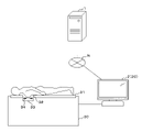
- FIG. 1 is an explanatory diagram showing a configuration example of an diagnostic imaging system.
- the diagnostic imaging system includes a server 1 and a diagnostic imaging device 2.
- the server 1 and the diagnostic imaging apparatus 2 are communicated and connected via the network N.
- the breast is mentioned as an example of the biological part to be image-diagnosed, but it may be another biological part.
- Server 1 is a server computer capable of various information processing and transmission / reception of information.
- the device corresponding to the server 1 is not limited to the server computer, and may be, for example, a personal computer or the like.
- the server 1 performs machine learning to learn predetermined training data, and when an ultrasonic image (for example, a tomographic image) captured by the diagnostic imaging apparatus 2 is input, the body movement of the subject, etc. It functions as a generator for generating a first model 51 (see FIG. 8) that detects blurring of an image due to the above.
- the data of the first model 51 generated by the server 1 is installed in the diagnostic imaging apparatus 2, and the diagnostic imaging apparatus 2 detects blurring from the captured image using the first model 51 and corrects the blur.
- the image diagnosis device 2 is an image diagnosis device for ultrasonic echo examination, and includes an image processing device 20 and an image pickup device 30.
- the image processing device 20 is a computer that functions as a console of the diagnostic imaging device 2, and in addition to generating (reconstructing) an ultrasonic tomographic image of the breast and displaying it, a plurality of tomographic images captured at a plurality of positions of the breast are displayed. Originally, a 3D image is generated and displayed.
- the image processing device 20 is not limited to the computer (console) for ultrasonic image diagnosis, and may be a general-purpose computer such as a personal computer.
- the image pickup device 30 is an image pickup device that transmits and receives ultrasonic signals. As shown in FIG. 1, the image pickup apparatus 30 is configured to be able to take an image of a breast while the subject is lying face down. Specifically, the image pickup apparatus 30 has a bed-like shape, and the top plate 31 is provided with a hole 32 for inserting a breast. A water tank 33 is provided below the hole 32, and the subject inserts the breast into the water tank 33 through the hole 32.
- the water tank 33 is provided with a ring array 34.
- the ring array 34 is a ring-shaped oscillator array including a plurality of ultrasonic elements 341 (transducers) (see FIG. 4).
- a plurality of ultrasonic elements 341 are arranged at equal intervals in the ring array 34, and each ultrasonic element 341 transmits an ultrasonic signal and receives a reflected wave.
- the image processing device 20 reconstructs the reflected wave data in a plurality of directions obtained from each ultrasonic element 341 to generate an ultrasonic tomographic image.
- the ring array 34 is configured to be movable in the vertical direction, and the diagnostic imaging apparatus 2 moves the ring array 34 up and down to take an image of a tomographic image at each position (height) of the drooping breast, and captures a tomographic image at a plurality of positions.
- a three-dimensional image is generated by reconstructing the tomographic image of.
- the ultrasonic diagnostic system described in International Publication No. 2017/051903 can be adopted.
- the diagnostic imaging apparatus 2 is not limited to the above configuration.
- an image diagnosis device using a handy scanner may be used instead of the bed-type image pickup device 30, an image diagnosis device using a handy scanner.
- the diagnostic imaging apparatus 2 captures an ultrasonic tomographic image of the breast.
- the diagnostic imaging apparatus 2 uses the above-mentioned first model 51 to detect blurring caused by body movement or the like from an ultrasonic tomographic image.
- the diagnostic imaging apparatus 2 corrects the tomographic image and generates a three-dimensional image using the corrected tomographic image.
- the server 1 generates (learns) the first model 51, but the local diagnostic imaging apparatus 2 may generate the first model 51. Further, in the present embodiment, the diagnostic imaging apparatus 2 detects blurring based on the first model 51, but the server 1 on the cloud may detect blurring using the first model 51. .. That is, the distinction between the two is convenient, and a single computer may perform a series of processes.
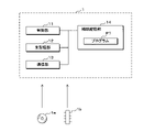
- FIG. 2 is a block diagram showing a configuration example of the server 1.
- the server 1 includes a control unit 11, a main storage unit 12, a communication unit 13, and an auxiliary storage unit 14.
- the control unit 11 has one or a plurality of processors such as a CPU (Central Processing Unit), an MPU (Micro-Processing Unit), and a GPU (Graphics Processing Unit), and reads out the program P1 stored in the auxiliary storage unit 14. By executing it, various information processing is performed.
- the main storage unit 12 is a temporary storage area for SRAM (Static Random Access Memory), DRAM (Dynamic Random Access Memory), flash memory, etc., and temporarily stores data necessary for the control unit 11 to execute arithmetic processing.
- SRAM Static Random Access Memory
- DRAM Dynamic Random Access Memory
- flash memory etc.
- the communication unit 13 is a communication module for performing processing related to communication, and transmits / receives information to / from the outside.
- the auxiliary storage unit 14 is a non-volatile storage area such as a large-capacity memory or a hard disk, and stores the program P1 and other data necessary for the control unit 11 to execute processing.
- the auxiliary storage unit 14 may be an external storage device connected to the server 1. Further, the server 1 may be a multi-computer composed of a plurality of computers, or may be a virtual machine virtually constructed by software.
- the server 1 is not limited to the above configuration, and may include, for example, an input unit that accepts operation input, a display unit that displays an image, and the like. Further, the server 1 includes a reading unit for reading a portable storage medium 1a such as a CD (CompactDisk) -ROM, a DVD (DigitalVersatileDisc) -ROM, and reads and executes a program P1 from the portable storage medium 1a. You can do it. Alternatively, the server 1 may read the program P1 from the semiconductor memory 1b.
- a portable storage medium 1a such as a CD (CompactDisk) -ROM, a DVD (DigitalVersatileDisc) -ROM
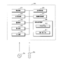
- FIG. 3 is a block diagram showing a configuration example of the image processing device 20.
- the image processing device 20 includes a control unit 21, a main storage unit 22, a communication unit 23, a display unit 24, an input unit 25, a transmission / reception unit 26, an image processing unit 27, and an auxiliary storage unit 28.
- the control unit 21 has one or a plurality of processors such as CPUs, and performs various information processing by reading and executing the program P2 stored in the auxiliary storage unit 28.
- the main storage unit 22 is a temporary storage area such as a RAM, and temporarily stores data necessary for the control unit 21 to execute arithmetic processing.
- the communication unit 23 is a communication module for performing processing related to communication, and transmits / receives information to / from the outside.
- the display unit 24 is a display screen such as a liquid crystal display and displays an image.
- the input unit 25 is an operation interface for a keyboard, a mouse, and the like, and receives operation input from the user.
- the transmission / reception unit 26 controls the ultrasonic element 341 of the ring array 34 to transmit / receive ultrasonic signals.
- the image processing unit 27 is a module that performs image processing (reconstruction), and preferably includes a processor having a high calculation processing capacity such as a GPU.
- the auxiliary storage unit 28 is a non-volatile storage area such as a hard disk and a large-capacity memory, and stores the program P2 and other data necessary for the control unit 21 to execute processing. Further, the auxiliary storage unit 28 stores the first model 51.
- the first model 51 is a machine learning model in which predetermined training data has been trained, and is a model for detecting blurring of an image when an ultrasonic tomographic image is input.
- the first model 51 is expected to be used as a program module constituting a part of artificial intelligence software.
- the image processing device 20 may include a reading unit that reads a portable storage medium 2a such as a CD-ROM, and may read the program P2 from the portable storage medium 2a and execute the program P2. Alternatively, the image processing device 20 may read the program P2 from the semiconductor memory 2b.
- a reading unit that reads a portable storage medium 2a such as a CD-ROM, and may read the program P2 from the portable storage medium 2a and execute the program P2.
- the image processing device 20 may read the program P2 from the semiconductor memory 2b.
- FIG. 4 is an explanatory diagram relating to the imaging process of the ultrasonic tomographic image.
- FIG. 4 conceptually illustrates how the diagnostic imaging apparatus 2 transmits and receives ultrasonic signals via the ring array 34 to generate (image) an ultrasonic tomographic image (second image) of the breast. The outline of the diagnostic imaging apparatus 2 will be described below.
- the image pickup apparatus 30 of the diagnostic imaging apparatus 2 has a ring array 34 in which a plurality of (for example, 150) ultrasonic elements 341 are provided at equal intervals, and an ultrasonic signal is transmitted through each ultrasonic element 341. Send and receive. Specifically, as illustrated by hatching in FIG. 1, the diagnostic imaging apparatus 2 transmits an ultrasonic signal with a fan-shaped region within a certain distance from the ultrasonic element 341 as an imaging region.
- the ultrasonic element 341 receives the reflected wave from the above-mentioned imaging region.
- the element that transmits the ultrasonic signal and the element that receives the reflected wave may be different.
- the diagnostic imaging apparatus 2 acquires the reflected wave data obtained by receiving the reflected wave by the ultrasonic element 341 as the original image data (first image) for generating (reconstructing) the ultrasonic tomographic image.
- an image reconstructed based on the reflected wave data obtained by receiving the reflected wave by the ultrasonic element 341 is referred to as a “fan image”.
- the image refers to a matrix of two-dimensional integers or real numbers.
- the diagnostic imaging apparatus 2 obtains by transmitting ultrasonic signals transmitted to a biological part from each of a plurality of directions by sequentially transmitting ultrasonic signals from each ultrasonic element 341 arranged along the circumference of the ring array 34. Get multiple fan images. Then, the image processing unit 27 of the image diagnostic apparatus 2 (image processing apparatus 20) reconstructs the plurality of fan images by the aperture synthesis method to generate a two-dimensional ultrasonic tomographic image.
- the diagnostic imaging apparatus 2 starts at an arbitrary ultrasonic element 341 and extends to the ultrasonic element 341 at the end point located next to the ultrasonic element 341.
- the ultrasonic element 341 that transmits an ultrasonic signal in a clockwise direction is sequentially changed to acquire an omnidirectional fan image (for example, 150 fan images).
- each fan image covers a fan-shaped space, and the fan images acquired by the adjacent ultrasonic elements 341 overlap each other in the imaging region.
- the diagnostic imaging apparatus 2 superimposes fan images in each direction to generate one tomographic image.
- the fan image used for aperture synthesis is reconstructed under the same sound velocity estimation value based on the received signal acquired under the same transmission condition regardless of the position of the transmission aperture.
- the diagnostic imaging apparatus 2 can also simultaneously transmit ultrasonic signals from a plurality of different transmission openings (ultrasonic element 341). For example, when acquiring 150 fan images per tomographic image, transmission may be performed 150 times starting from a certain direction as described above, but the directions (angles) are different by 120 degrees at three locations. By transmitting from the ultrasonic element 341 at the same time and sequentially changing the three ultrasonic elements 341 along the ring array 34, the image pickup of the fan image may be completed in 50 transmissions. Further, in the present embodiment, the ultrasonic element 341 is described as being arranged in an annular shape around the breast, but the arrangement shape is not limited to the annular shape and may be arranged in another shape. ..
- the diagnostic imaging apparatus 2 can acquire a plurality of fan images by sequentially transmitting ultrasonic signals in a plurality of times from a plurality of ultrasonic elements 341 arranged so as to surround the periphery of the breast (living body part).
- the number of transmissions of the ultrasonic signal and the arrangement shape of the ultrasonic element 341 are not particularly limited.
- each of the plurality of fan images includes at least a part of the tomographic image imaging region on substantially the same plane, and is a set of images in which at least one of different fan images and a part of the imaging region overlap.
- FIG. 5 is an explanatory diagram showing the relationship between the measurement time and body movement in ultrasonic imaging.
- the rate-determining time for imaging is the speed of sound propagating in the living body and in the water. It depends on the structure and temperature, but it is about 1500 m / s.
- the side length is 15 cm.
- the round-trip propagation time is 0.2 ms.
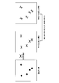
- FIG. 6 is an explanatory diagram showing the relationship between the position of the transmission opening and the point response function.
- the ultrasonic scattered image based on the reflected wave data obtained by ultrasonic imaging is represented by a point response function indicating the basic performance of imaging and a convolution integral of the scattering body distribution in the imaging target.
- the point response function PSF is the angle between the distance from the aperture and the line segment connecting the center of the ring array 34 and the center of the transmission aperture with the reference line under ideal conditions that do not consider the inhomogeneity of the speed of sound. It becomes a function of. That is, strictly speaking, the point response function does not have a shape that is rotationally symmetric with respect to the point at which the output value of the point response function takes the maximum value.
- the scattered image is a method of adding signals obtained by a plurality of receiving elements and outputting an image, but a method other than necessarily adding when outputting one pixel signal from a signal of the number of receiving elements.
- this embodiment can also be applied to a method of extracting dynamic information such as blood flow and contrast medium from changes in scattered signals over time and visualizing information on the spatial distribution of blood flow. Is.
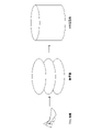
- FIG. 7 is an explanatory diagram regarding the generation process of the three-dimensional image.
- FIG. 7 conceptually illustrates how a tomographic image (center of FIG. 7) is generated from a plurality of fan images (left of FIG. 7) and a three-dimensional image (right of FIG. 7) is further generated from a plurality of tomographic images. There is.
- the diagnostic imaging apparatus 2 reconstructs a plurality of fan images obtained by imaging the breast from each direction and generates a two-dimensional ultrasonic tomographic image.
- the diagnostic imaging apparatus 2 moves the ring array 34 up and down to generate tomographic images of breasts at different positions (heights) along one direction (up and down direction).
- the image processing unit 27 of the diagnostic imaging apparatus 2 reconstructs a plurality of tomographic images (frames) arranged along one direction to generate a three-dimensional image of the breast.
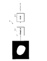
- FIG. 8 is an explanatory diagram regarding blur detection processing.
- FIG. 8 conceptually illustrates a state in which an ultrasonic tomographic image of a breast is input to the first model 51 and blurring of the image due to body movement or the like is detected.
- the diagnostic imaging apparatus 2 generates an ultrasonic tomographic image from a plurality of fan images.
- the tomographic image may be blurred.
- Examples of the cause of this blurring include those caused by the body movement of the subject (so-called motion artifact), the misalignment of the device (ring array 34), and the like.
- the image diagnostic apparatus 2 estimates the sound wave velocity of the ultrasonic wave to generate an image, the position estimation of the subject may be deviated due to the error in the sound velocity estimation, which may cause blurring.
- These blurs are caused by multiple acquisition data that are actually acquired at different timings in time in a plane or stereoscopic imaging region that is supposed to be acquired simultaneously in time in the process of aperture synthesis.
- Blurring occurs due to compositing.
- the present embodiment by detecting the positional deviation between the fan images, it is possible to reduce the blurring caused by the positional deviation between the fan images or between the fan image and the imaging space coordinates that occurs during aperture synthesis. be.
- the diagnostic imaging apparatus 2 detects the blurring of the tomographic image using the first model 51.
- the first model 51 is a machine learning model in which predetermined training data has been trained, and is a model for detecting blurring of a tomographic image when an ultrasonic tomographic image is input.
- a BRISQUE Blind / Referenceless Image Spatial Quality Evaluator
- SVM Small Vector Machine
- the BRISQUE is an algorithm that evaluates the quality of an image without the need for a reference image.
- the first model 51 includes a feature amount extractor 511 and a detector 512.
- the feature amount extractor 511 is an extractor that extracts the feature amount of the input image.
- the feature amount is the average luminance, the dispersion of the luminance, the skewness of the luminance, the kurtosis of the luminance, the entropy, and the like, but the parameters thereof are not particularly limited.
- the feature amount extractor 511 generates a feature amount vector from the input tomographic image and inputs it to the detector 512.
- the detector 512 is an SVM that detects blurring based on the feature amount of the tomographic image.
- the detector 512 has learned the determination boundary for discriminating between the spatial area determined to have blurring and the spatial area determined to have no blurring. It is a model and detects blurring based on the feature amount input from the feature amount extractor 511.
- the detector 512 according to the present embodiment is configured as a regression model for calculating a score indicating the degree of blurring, calculates the score based on the feature amount of the tomographic image, and determines the presence or absence of blurring based on the calculated score. judge.
- the detector 512 is described as a regression model that calculates a score indicating the degree of blurring, but it may be a classification model that performs binary classification as to whether or not there is blurring.
- the BRISQUE model is given as an example of the first model 51, but the first model 51 may be a model based on other learning algorithms such as a neural network, a decision tree, and a random forest.
- the server 1 learns the ultrasonic tomographic image of the subject imaged in the past as training data, generates the first model 51, and installs it in the diagnostic imaging apparatus 2.
- the server 1 may use the tomographic image in which blurring is actually observed as training data, but in the present embodiment, the tomographic image without blurring is artificially blurred and used as training data.
- the server 1 performs predetermined coordinate transformations (fine movements in the X and Y directions, fine rotations, etc.) simulating body movements on a plurality of fan images constituting a tomographic image without blurring.
- the server 1 may perform coordinate conversion on all the fan images constituting one tomographic image, or may perform coordinate conversion on only a part of the fan images.
- the server 1 generates an artificially blurred tomographic image by reconstructing a plurality of fan images after coordinate conversion.
- the server 1 uses the tomographic image before blurring and the tomographic image after blurring as training data to generate the first model 51.
- Server 1 first performs segmentation for each tomographic image for training and extracts the image area corresponding to the breast.
- the image area corresponding to the breast is shown in white, and the image area other than the breast is shown in black.
- the segmentation may be performed by detecting the contour of the breast by pattern matching, or may be performed by using a machine learning model such as CNN (Convolution Neural Network). Further, the original tomographic image may be used as it is without performing segmentation.
- CNN Convolution Neural Network
- the server 1 inputs the image areas extracted from the original tomographic image without blurring and the tomographic image with blurring into the feature amount extractor 511, and extracts the feature amount of the image area. Then, the server 1 generates the detector 512 based on the feature amount of each tomographic image (image area) with a class label indicating the presence or absence of blurring. That is, when the tomographic image is mapped to the feature amount space according to the feature amount, the server 1 discriminates between a spatial area for determining that the tomographic image has blur and a spatial area for determining that the tomographic image has no blur. Derivation of the decision boundary to be made. From the above, the server 1 generates the first model 51.
- the diagnostic imaging apparatus 2 detects blurring from the tomographic image of the subject's breast using the above-mentioned first model 51. That is, the diagnostic imaging apparatus 2 performs segmentation of the tomographic image to extract an image region corresponding to the breast, and inputs the image region to the feature amount extractor 511 to extract the feature amount. Then, the diagnostic imaging apparatus 2 inputs the extracted feature amount to the detector 512, calculates a score indicating the degree of blurring, and determines the presence or absence of blurring. For example, the diagnostic imaging apparatus 2 determines whether or not the calculated score is equal to or higher than a predetermined threshold value.
- the diagnostic imaging apparatus 2 may accept a setting input for setting (changing) a threshold value to be compared with the score from the user (medical worker). As a result, the user can arbitrarily determine the degree of blurring to be corrected.
- the diagnostic imaging apparatus 2 corrects the tomographic image where the blurring is detected. Specifically, the diagnostic imaging apparatus 2 aligns a plurality of fan images constituting a tomographic image with each other.
- the breast as a subject of the present invention is a non-rigid body. Therefore, the rigid body registration method cannot be used. In addition, it is necessary to specify a landmark for non-rigid registration. However, in diagnosis, it is a time-consuming task for a person (doctor) to select landmarks for each image and specify their positions. Therefore, in the present invention, the structure in the breast automatically extracted by the program by the edge image extracted from the part (edge) where the brightness of the image changes discontinuously is used as a landmark.
- the diagnostic imaging apparatus 2 first detects the edge of each fan image and generates a plurality of edge images obtained by extracting the edge from each fan image.
- an example of using connective tissue and Cooper's ligament as breast landmarks will be described. Since the connective tissue and the Cooper's ligament have a linear structure, the connective tissue and the Cooper's ligament can be taken out by applying an edge detection filter.
- a Gabor filter As a method of generating an edge image, for example, a Gabor filter is used.
- the control unit 21 applies a breast region mask to the fan image. For example, a fan image with zero brightness in the extramammary region is generated.
- the control unit 21 further applies a Gabor filter to each of the obtained fan images to generate a magnitude image.
- the control unit 21 calculates the average brightness of the brightness of the obtained magnitude image and generates an edge image.
- the parameters of the Gabor filter are, for example, an angle ⁇ of 0, 45, 90, ..., 315.
- a Sobel Filter can be used as another example of the method of generating an edge image.
- the control unit 21 applies a breast region mask to the fan image to generate a fan image in which the brightness of the extramammary region is zero.
- the control unit 21 applies a 2D Sobel filter to each of the obtained fan images to generate an edge image.
- the method for generating an edge image is not limited to the methods described above, and any filter that can selectively extract a linear structure may be used. By performing the alignment using the edge image obtained in this way, it is possible to perform the alignment so that the positions of the connective tissues match in the two images.
- the diagnostic imaging apparatus 2 calculates an edge motion vector (vector value indicating the amount of edge movement and the direction of movement) between two adjacent edge images, and based on the calculated motion vector, positions the fan images with each other. Calculate the alignment function for alignment.
- the "two adjacent edge images” refer to two edge images corresponding to the two fan images acquired by the two adjacent ultrasonic elements 341 in the ring array 34.
- the diagnostic imaging apparatus 2 uses, for example, a TV-L1 optical flow or the like to calculate an alignment function of two fan images so that the evaluation value representing the degree of coincidence between the two edge images is maximized.
- the diagnostic imaging apparatus 2 sequentially evaluates the degree of coincidence between adjacent edge images for all edge images, and calculates a fan image alignment function.
- the diagnostic imaging apparatus 2 reconstructs a plurality of fan images while performing alignment of each fan image based on the calculated alignment function, and regenerates a tomographic image.
- Aligning fan images means aligning each fan image before generating (reconstructing) the tomographic image, and shifting the relative coordinates of each fan image in the process of generating the tomographic image. By superimposing the images while superimposing them, it is possible to include the case of alignment during the generation of the tomographic image.
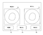
- FIG. 9 is an explanatory diagram showing an example of a display screen of the diagnostic imaging apparatus 2.
- FIG. 9 shows an example of a screen displayed on the display unit 24 by the diagnostic imaging apparatus 2 (image processing apparatus 20), which is a tomographic image before applying the alignment function (before correction) and after applying the alignment function.
- An example of a screen displaying a tomographic image (after correction) is shown.
- the diagnostic imaging apparatus 2 performs the above correction and displays the tomographic image before and after the correction.
- the screen includes a pre-correction image 71, a post-correction image 72, a re-imaging button 73, a pre-correction image selection button 74, and a post-correction image selection button 75.
- the uncorrected image 71 is a tomographic image before correction (a tomographic image in which blurring is detected), and the corrected image 72 is a tomographic image after correction.
- the image diagnostic apparatus 2 displays the pre-correction image 71 and the post-correction image 72, and presents the user with the state before and after the correction.
- the re-imaging button 73 is a button for selecting whether or not re-imaging is necessary. For example, when the tomographic image is so blurry that it cannot be used for diagnosis even if it is corrected, the user operates the re-imaging button 73 to perform re-imaging. When the operation input to the re-imaging button 73 is received, the diagnostic imaging apparatus 2 performs re-imaging, acquires a fan image, and generates a tomographic image.
- the reimaging may be performed on the breast cross section at all positions (height), or may be performed only on the breast cross section at the position (height) where blurring is detected.
- the diagnostic imaging apparatus 2 may automatically determine the necessity of reimaging. For example, the diagnostic imaging apparatus 2 determines whether or not the score is extremely high by comparing the score obtained by inputting the tomographic image into the first model 51 with a predetermined threshold value. As a result, the diagnostic imaging apparatus 2 determines whether or not reimaging is necessary due to severe blurring. When it is determined that reimaging is necessary, the diagnostic imaging apparatus 2 displays, for example, on the screen of FIG. 9 that reimaging is necessary, and prompts the user to reimage. Alternatively, the diagnostic imaging apparatus 2 may automatically start reimaging when it is determined that reimaging is necessary.
- the diagnostic imaging apparatus 2 may detect an artifact other than blurring from the tomographic image, and if an artifact other than blurring is detected, it may be determined that reimaging is necessary.
- an artifact for example, a state in which the subject moves greatly and the subject (breast) is not shown can be considered.
- the above artifact is an example, and other artifacts may be detected.
- the diagnostic imaging apparatus 2 may train the first model 51 to learn a tomographic image having an artifact other than blurring, or an artifact other than blurring by a detection algorithm other than the first model 51 (image pattern matching, etc.). May be detectable. In this way, the diagnostic imaging apparatus 2 may detect an artifact other than the blur from the tomographic image and determine whether or not reimaging is necessary.
- the pre-correction image selection button 74 and the post-correction image selection button 75 are buttons for selecting a tomographic image to be used for generating a three-dimensional image (third image) from the tomographic images before and after the correction.
- the diagnostic imaging apparatus 2 accepts the selection input of the tomographic image used for generating the three-dimensional image by accepting the operation input to any of the buttons.
- the diagnostic imaging apparatus 2 reconstructs a tomographic image selected by the user and another tomographic image in which blurring is not detected, and generates a three-dimensional image.
- the diagnostic imaging apparatus 2 displays the generated three-dimensional image.
- the present embodiment blurring due to body movement or the like is detected from the tomographic image, and when blurring is detected, the tomographic image is obtained by aligning the plurality of fan images constituting the tomographic image. Regenerate. Thereby, the influence of body movement and the like can be removed or reduced, and the ultrasonic image diagnosis can be suitably supported.
- a BRISQUE model is adopted as the first model 51 for detecting blurring, and alignment based on a motion vector such as an optical flow is adopted as an image correction means.
- the control unit 21 which is a general-purpose processor
- the image processing unit 27 GPU or the like
- the time required for image processing can be suppressed.
- the present embodiment in order to generate a tomographic image of one plane, it is possible to detect the relative positional deviation between the subject and the ultrasonic element 341 that may occur while acquiring a plurality of fan images. ..
- ultrasonic signals are sequentially transmitted in one direction from ultrasonic elements 341 arranged in an annular shape to acquire a plurality of fan images
- continuous body movements are also accumulated and a sudden body is generated. Since the probability of motion also increases, the effect of body motion increases as the time points for capturing each fan image are separated in time. Therefore, the degree of disagreement between images separated in time tends to increase. This point becomes remarkable between the fan image at the start point position of the ring array 34, that is, the fan image at the first time, and the fan image at the end point position, that is, the fan image at the final round.
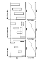
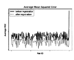
- FIG. 10 is an example of comparing the degree of disagreement between 150 fan images adjacent to each other in space.
- the graph of FIG. 10 shows the calculation result of calculating the degree of disagreement (average value of MSE (Mean squared error) of luminance) between adjacent fan images among the fan images captured from 150 directions.
- the horizontal axis represents the data points representing the pair of the i-th fan image and the i + 1-th fan image
- the vertical axis represents the degree of disagreement between the fan images.
- the last data point is a comparison between the 149th fan image and the 0th fan image, that is, the final and first fan images.
- the two fan images are spatially adjacent to each other, and the imaging regions overlap each other.
- the time points of imaging of the two fan images are separated from each other in time, body movement is likely to occur between them, and when the degree of disagreement between the fan images is confirmed, the degree of disagreement of this pair is often the largest. Therefore, the image quality is greatly improved by aligning the two fan images with each other.
- FIG. 11 is a flowchart showing the procedure of the generation process of the first model 51. Based on FIG. 11, the processing contents when the first model 51 is generated by machine learning will be described.
- the control unit 11 of the server 1 acquires a plurality of tomographic images of the breast (living body site) of the subject imaged (generated) in the past without blurring in the image (step S11). ..
- the control unit 11 generates a tomographic image for training with blurring added to each tomographic image (step S12). Specifically, the control unit 11 performs predetermined coordinate conversion simulating body movement on a plurality of fan images constituting each of the tomographic images without blurring.
- the control unit 11 reconstructs a plurality of fan images after coordinate conversion to generate an artificially blurred tomographic image.
- the control unit 11 performs segmentation on the non-blurred tomographic image acquired in step S11 and the tomographic image with blurring in step S12, and extracts an image region corresponding to the breast from each tomographic image (step). S13). Then, the control unit 11 generates the first model 51 based on the image area of each extracted tomographic image (step S14). Specifically, as described above, the control unit 11 generates a BRISQUE model including the feature amount extractor 511 and the detector 512 (SVM) as the first model 51. The control unit 11 inputs the image area extracted from each tomographic image for training into the feature amount extractor 511 and extracts the feature amount.
- SVM detector 512
- the control unit 11 generates the detector 512 based on the feature amount of each tomographic image (image area) with a class label indicating the presence or absence of blurring. That is, the control unit 11 determines that when each tomographic image is mapped to the feature amount space according to the feature amount, the spatial area determined to have blurring and the spatial area determined to have no blurring are discriminated. Derivation of boundaries. The control unit 11 ends a series of processes.
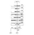
- FIG. 12 is a flowchart showing the procedure of the image imaging process.
- the processing contents executed by the diagnostic imaging apparatus 2 will be described with reference to FIG.
- the control unit 21 of the diagnostic imaging apparatus 2 (image processing apparatus 20) transmits an ultrasonic signal from each ultrasonic element 341 of the ring array 34, and receives a reflected wave of the ultrasonic signal transmitted from each ultrasonic element 341.
- the plurality of fan images (reflected wave data, first image) obtained in the above are acquired (step S31).
- the control unit 21 transmits and receives ultrasonic signals while moving the ring array 34 in the vertical direction, and acquires a fan image of the breast from each direction at different positions (heights) of the breast.
- the image processing unit 27 generates an ultrasonic tomographic image (second image) obtained by reconstructing a plurality of acquired fan images (step S32). Specifically, the image processing unit 27 generates a plurality of tomographic images at different positions (heights) of the breasts along one direction (vertical direction).
- the control unit 21 performs segmentation on each tomographic image and extracts an image region corresponding to the breast (step S33). Then, the control unit 21 inputs the image region extracted from each tomographic image into the first model 51, and detects the blurring of each tomographic image (step S34). Specifically, the control unit 21 inputs the image area of each tomographic image to the feature amount extractor 511 to extract the feature amount, and inputs the extracted feature amount to the detector 512 to indicate the degree of blurring. Is calculated, and the presence or absence of blurring is determined according to the calculated score.
- the control unit 21 determines whether or not blurring is detected in each tomographic image as a result of the processing in step S34 (step S35). When it is determined that blurring is not detected (S35: NO), the control unit 21 shifts the process to step S42.
- the control unit 21 When it is determined that blurring is detected (S35: YES), the control unit 21 generates an edge image obtained by extracting the edge of the fan image for each of the plurality of fan images constituting the tomographic image in which blurring is detected (step). S36). The control unit 21 calculates the motion vector of the edge between the adjacent edge images, and calculates the alignment function for aligning the fan images based on the calculated motion vector (step S37). The image processing unit 27 generates a tomographic image while aligning the fan images with each other based on the calculated alignment function (step S38).
- the control unit 21 displays the tomographic image before and after the correction on the display unit 24 (step S39). That is, the control unit 21 displays the tomographic image generated in step S32 and the tomographic image generated in step 38.
- the control unit 21 receives from the user a selection input for selecting the necessity of reimaging, and determines whether or not to perform reimaging (step S40). As described above, the control unit 21 may automatically determine the necessity of reimaging by detecting high or low scores indicating the degree of blurring calculated above, or artifacts other than blurring. .. When it is determined to perform reimaging (S40: YES), the control unit 21 returns the process to step S31.
- the control unit 21 selects a tomographic image to be used for generating a three-dimensional image (third image) from the tomographic images before and after the correction displayed in step S39. Accepts selection input (step S41).
- the image processing unit 27 generates a three-dimensional image of the breast based on the selected tomographic image and other tomographic images in which blurring is not detected and displays it on the display unit 24 (step S42).
- the control unit 21 ends a series of processes.
- blurring is detected from the ultrasonic tomographic image (second image) obtained by reconstructing the fan image, but the present embodiment is not limited to this, and the fan that is the source of the tomographic image is not limited to this. Blurring may be detected from the image (first image).
- the blurring of the image is suitably detected by using the first model 51, and the image is corrected to remove or reduce the blurring, thereby suitably supporting the ultrasonic image diagnosis. can do.
- FIG. 16 is a flowchart showing another example of the procedure of the image imaging process. The process shown in FIG. 16 is obtained by adding steps S341 to S344 in place of step S34 in the process shown in FIG. The same steps as in FIG. 12 will be omitted. In addition, in FIG. 16, the illustration of steps S36 to S42 in FIG. 12 is omitted.
- the control unit 21 of the diagnostic imaging apparatus 2 executes the following process after executing the process of step S33. Specifically, the control unit 21 inputs the image area of each tomographic image to the feature amount extractor 511 to extract the feature amount, and inputs the extracted feature amount to the detector 512 to indicate the degree of blurring. Is calculated (step S341). Next, the control unit 21 acquires a tomographic image adjacent to each tomographic image for each tomographic image (step S342). For example, the control unit 21 has one adjacent tomographic image whose imaging position (height) is adjacent to one in the upward or downward direction with respect to one tomographic image (the tomographic image of interest), or two adjacent tomographic images in both directions.
- the control unit 21 calculates the degree of disagreement between each tomographic image and the adjacent tomographic image of each tomographic image (step S343). For example, the control unit 21 calculates the cumulative value of the difference between the pixel values of the corresponding pixels in each tomographic image and the adjacent tomographic image thereof, and sets the calculated cumulative value as the degree of mismatch.
- the control unit 21 determines the degree of disagreement between each tomographic image and the adjacent tomographic image directly above each tomographic image, or the degree of disagreement with the adjacent tomographic image immediately below. Is calculated.
- the control unit 21 determines the degree of disagreement between each tomographic image and the adjacent tomographic image directly above each tomographic image, and the degree of disagreement with the adjacent tomographic image immediately below. calculate.
- control unit 21 detects the presence or absence of blurring of each tomographic image based on the score indicating the degree of blurring calculated in step S341 and the degree of disagreement with the adjacent tomographic image calculated in step S343 (S344). .. For example, the control unit 21 determines whether or not the calculated score is equal to or higher than a predetermined threshold value, and also determines whether or not the calculated degree of mismatch is equal to or higher than a predetermined threshold value, and the score is equal to or higher than the predetermined threshold value. If it is determined that the degree of inconsistency is equal to or higher than a predetermined threshold value, it is determined that the tomographic image is blurred.
- the control unit 21 may determine that the tomographic image is blurred when it is determined that the score is equal to or higher than a predetermined threshold value or when it is determined that the degree of disagreement is equal to or higher than a predetermined threshold value.
- the diagnostic imaging apparatus 2 may be configured to accept a setting input (setting change) from a user (medical worker) for a threshold value to be compared with the degree of disagreement. As a result, the user can arbitrarily determine the degree of inconsistency to be corrected.
- Embodiment 2 In the first embodiment, a mode in which blurring is detected and corrected when the fan image is reconstructed into a tomographic image has been described. In this embodiment, a mode in which blurring is detected and corrected when a tomographic image (first image) is reconstructed into a three-dimensional image (second image) will be described. The contents overlapping with the first embodiment are designated by the same reference numerals and the description thereof will be omitted.
- FIG. 13 is a block diagram showing a configuration example of the image processing device 20 according to the second embodiment.
- the auxiliary storage unit 28 of the image processing device 20 according to the present embodiment stores the second model 52.
- the second model 52 is a machine learning model in which predetermined training data has been trained, and is a model for detecting blurring of a three-dimensional image when a three-dimensional image of a breast is input.
- the second model 52 is expected to be used as a program module constituting a part of artificial intelligence software.
- the second model 52 has the same configuration as the first model 51.
- the first model 51 that detects blurring from a tomographic image and the second model 52 that detects blurring from a three-dimensional image are described as separate models, but they are the same. It may be a model.
- the diagnostic imaging apparatus 2 detects blurring from a three-dimensional image in which a plurality of tomographic images are reconstructed, and aligns the tomographic images constituting the three-dimensional image.
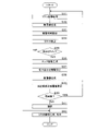
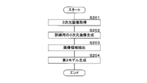
- FIG. 14 is a flowchart showing the procedure of the generation process of the second model 52. Based on FIG. 14, the processing content when the second model 52 is generated by machine learning will be described.
- the control unit 11 of the server 1 acquires a plurality of three-dimensional images of the breast of the subject that have been generated (imaged) in the past without blurring in the images (step S201).
- the control unit 11 generates a training 3D image in which blur is added to each 3D image (step S202).
- the control unit 11 performs predetermined coordinate conversion simulating body movement on a plurality of tomographic images constituting a three-dimensional image without blurring, and reconstructs the plurality of tomographic images after the coordinate conversion. To generate a three-dimensional image with blurring.
- the control unit 11 extracts an image region corresponding to the breast from each of the non-blurred 3D image and the blurred 3D image (step S203).
- the control unit 11 generates a second model 52 that detects blurring of the 3D image when a 3D image is input based on the extracted image area (step S204).
- the control unit 11 ends a series of processes.
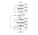
- FIG. 15 is a flowchart showing the procedure of the image imaging process according to the second embodiment.
- the diagnostic imaging apparatus 2 executes the following process.
- the image processing unit 27 of the image diagnostic apparatus 2 (image processing apparatus 20) generates a three-dimensional image in which a plurality of tomographic images (first images) captured at different positions of the breast are reconstructed (step S221).
- the control unit 21 extracts an image region corresponding to the breast from the generated three-dimensional image (step S222).
- the control unit 21 inputs the extracted image area to the second model 52 and detects blurring of the three-dimensional image (step S223).
- the control unit 21 determines whether or not blurring is detected as a result of the processing in step S223 (step S224). When it is determined that blurring is not detected (S224: NO), the control unit 21 shifts the process to step S228.
- the control unit 21 When it is determined that blurring is detected (S224: YES), the control unit 21 generates an edge image obtained by extracting the edge of the tomographic image for each of the plurality of tomographic images constituting the three-dimensional image (step S225).
- the control unit 21 calculates an edge motion vector between adjacent edge images, and calculates an alignment function between a plurality of tomographic images based on the calculated motion vector (step S226).
- the control unit 21 generates a three-dimensional image while aligning the tomographic images with each other based on the calculated alignment function (step S227).
- the control unit 21 displays the three-dimensional image generated in step S221 or S227 on the display unit 24 (step S228), and ends a series of processes.
- the diagnostic imaging apparatus 2 may display three-dimensional images before and after the correction, and may be able to select whether or not reimaging is necessary and whether or not the correction is necessary.
- the diagnostic imaging apparatus 2 detects blurring from the tomographic image (first image) before reconstruction instead of the three-dimensional image (second image) after reconstruction, and aligns the tomographic image. May be good.
- blurring can be detected and corrected even when a three-dimensional image is generated.
Abstract
L'invention concerne un dispositif d'imagerie diagnostique et similaire susceptible d'aider de manière appropriée lors d'une imagerie diagnostique ultrasonore. Un dispositif d'imagerie diagnostique (2) comprend : une unité d'acquisition qui acquiert une pluralité de premières images obtenues par imagerie d'un site de corps vivant d'un sujet sur la base d'un signal ultrasonore ; une unité de génération qui génère une seconde image en reconstituant la pluralité de premières images ; une unité de détection qui entre les premières images acquises ou la seconde image générée dans un modèle appris pour détecter un flou, le modèle appris ayant été entraîné pour détecter un flou dans les premières images ou la seconde image lorsque les premières images ou la seconde image sont entrées ; et une unité de calcul qui, lorsque le flou est détecté, calcule une fonction de correspondance de position pour mettre en correspondance des positions de la pluralité de premières images. L'unité de génération génère la seconde image sur la base de la pluralité de premières images et de la fonction de correspondance de position.
Priority Applications (1)
| Application Number | Priority Date | Filing Date | Title |
|---|---|---|---|
| JP2022533229A JP7233792B2 (ja) | 2020-11-30 | 2021-11-26 | 画像診断装置、画像診断方法、プログラム及び機械学習用訓練データの生成方法 |
Applications Claiming Priority (2)
| Application Number | Priority Date | Filing Date | Title |
|---|---|---|---|
| JP2020-198664 | 2020-11-30 | ||
| JP2020198664 | 2020-11-30 |
Publications (1)
| Publication Number | Publication Date |
|---|---|
| WO2022114131A1 true WO2022114131A1 (fr) | 2022-06-02 |
Family
ID=81755642
Family Applications (1)
| Application Number | Title | Priority Date | Filing Date |
|---|---|---|---|
| PCT/JP2021/043404 WO2022114131A1 (fr) | 2020-11-30 | 2021-11-26 | Dispositif d'imagerie diagnostique, procédé d'imagerie diagnostique, programme et procédé de création de données d'entraînement pour apprentissage automatique |
Country Status (2)
| Country | Link |
|---|---|
| JP (1) | JP7233792B2 (fr) |
| WO (1) | WO2022114131A1 (fr) |
Citations (3)
| Publication number | Priority date | Publication date | Assignee | Title |
|---|---|---|---|---|
| WO2019082892A1 (fr) * | 2017-10-24 | 2019-05-02 | 株式会社Lily MedTech | Système et procédé de diagnostic par ultrasons |
| US20190350534A1 (en) * | 2018-05-16 | 2019-11-21 | Siemens Healthcare Gmbh | System and method for determining an imaging modality and the parameters therefor |
| JP2020531074A (ja) * | 2017-08-17 | 2020-11-05 | コーニンクレッカ フィリップス エヌ ヴェKoninklijke Philips N.V. | 画像アーチファクト特定及び除去のための深層学習ネットワークを有する超音波システム |
Family Cites Families (3)
| Publication number | Priority date | Publication date | Assignee | Title |
|---|---|---|---|---|
| US20130090560A1 (en) * | 2010-07-14 | 2013-04-11 | Go Kotaki | Ultrasound image reconstruction method, device therefor, and ultrasound diagnostic device |
| WO2014038703A1 (fr) * | 2012-09-10 | 2014-03-13 | 株式会社東芝 | Appareil échographique diagnostique, dispositif de traitement d'image médicale et programme de traitement d'image |
| US11064891B2 (en) * | 2014-09-05 | 2021-07-20 | Canon Kabushiki Kaisha | Object information acquiring apparatus |
-
2021
- 2021-11-26 JP JP2022533229A patent/JP7233792B2/ja active Active
- 2021-11-26 WO PCT/JP2021/043404 patent/WO2022114131A1/fr active Application Filing
Patent Citations (3)
| Publication number | Priority date | Publication date | Assignee | Title |
|---|---|---|---|---|
| JP2020531074A (ja) * | 2017-08-17 | 2020-11-05 | コーニンクレッカ フィリップス エヌ ヴェKoninklijke Philips N.V. | 画像アーチファクト特定及び除去のための深層学習ネットワークを有する超音波システム |
| WO2019082892A1 (fr) * | 2017-10-24 | 2019-05-02 | 株式会社Lily MedTech | Système et procédé de diagnostic par ultrasons |
| US20190350534A1 (en) * | 2018-05-16 | 2019-11-21 | Siemens Healthcare Gmbh | System and method for determining an imaging modality and the parameters therefor |
Also Published As
| Publication number | Publication date |
|---|---|
| JPWO2022114131A1 (fr) | 2022-06-02 |
| JP7233792B2 (ja) | 2023-03-07 |
Similar Documents
| Publication | Publication Date | Title |
|---|---|---|
| JP6280676B2 (ja) | 脊柱配列推定装置、脊柱配列推定方法及び脊柱配列推定プログラム | |
| JP4299189B2 (ja) | 超音波診断装置及び画像処理方法 | |
| JP6930283B2 (ja) | 画像処理装置、画像処理装置の作動方法、及び画像処理プログラム | |
| US10743844B2 (en) | Ultrasound imaging apparatus | |
| CN102727258B (zh) | 图像处理装置、超声波摄影系统及图像处理方法 | |
| US20170164923A1 (en) | Image Processor, Ultrasound Diagnostic Device Including Same, And Image Processing Method | |
| CN112367915A (zh) | 医学图像处理装置、医学图像处理方法和程序 | |
| CN109124662B (zh) | 肋骨中心线检测装置及方法 | |
| CN113557714A (zh) | 医学图像处理装置、医学图像处理方法和程序 | |
| JP7183590B2 (ja) | 眼科画像処理装置、oct装置、および眼科画像処理プログラム | |
| JP7071240B2 (ja) | 検査支援装置、方法およびプログラム | |
| CN113712594A (zh) | 医用图像处理装置以及医用摄像装置 | |
| WO2022071264A1 (fr) | Programme, procédé de génération de modèle, dispositif de traitement d'informations et procédé de traitement d'informations | |
| JP5177606B1 (ja) | 3次元超音波画像作成方法およびプログラム | |
| EP4129197A1 (fr) | Programme informatique, procédé de traitement d'informations, dispositif de traitement d'informations et procédé de génération de modèle | |
| WO2022114131A1 (fr) | Dispositif d'imagerie diagnostique, procédé d'imagerie diagnostique, programme et procédé de création de données d'entraînement pour apprentissage automatique | |
| CN112767403A (zh) | 医学影像分割模型训练方法、医学影像分割方法及装置 | |
| US20230281837A1 (en) | Method and system for registering images acquired with different modalities for generating fusion images from registered images acquired with different modalities | |
| KR20090110348A (ko) | 물체 형상 생성 방법, 물체 형상 생성 장치 및 프로그램 | |
| KR20230050253A (ko) | 흉막 삼출의 검출 방법 및 이를 위한 장치 | |
| JP7294996B2 (ja) | 超音波診断装置及び表示方法 | |
| Zeng et al. | Automatic segmentation of vertebral features on ultrasound spine images using Stacked Hourglass Network | |
| CN112515705A (zh) | 用于投影轮廓启用的计算机辅助检测(cad)的方法和系统 | |
| WO2023053755A1 (fr) | Dispositif d'aide au diagnostic d'image, procédé d'aide au diagnostic d'image et programme d'assistance au diagnostic d'image | |
| WO2023032954A1 (fr) | Procédé de traitement d'informations, programme et dispositif de diagnostic d'image |
Legal Events
| Date | Code | Title | Description |
|---|---|---|---|
| ENP | Entry into the national phase |
Ref document number: 2022533229 Country of ref document: JP Kind code of ref document: A |
|
| 121 | Ep: the epo has been informed by wipo that ep was designated in this application |
Ref document number: 21898103 Country of ref document: EP Kind code of ref document: A1 |
|
| NENP | Non-entry into the national phase |
Ref country code: DE |
|
| 122 | Ep: pct application non-entry in european phase |
Ref document number: 21898103 Country of ref document: EP Kind code of ref document: A1 |