WO2022107322A1 - Button switch, operating panel, and method for removing button switch - Google Patents
Button switch, operating panel, and method for removing button switch Download PDFInfo
- Publication number
- WO2022107322A1 WO2022107322A1 PCT/JP2020/043443 JP2020043443W WO2022107322A1 WO 2022107322 A1 WO2022107322 A1 WO 2022107322A1 JP 2020043443 W JP2020043443 W JP 2020043443W WO 2022107322 A1 WO2022107322 A1 WO 2022107322A1
- Authority
- WO
- WIPO (PCT)
- Prior art keywords
- opening
- button
- button base
- support member
- button switch
- Prior art date
Links
- 238000000034 method Methods 0.000 title claims description 8
- 210000000078 claw Anatomy 0.000 claims description 43
- 239000002184 metal Substances 0.000 claims description 22
- 229910052751 metal Inorganic materials 0.000 claims description 22
- 238000003780 insertion Methods 0.000 abstract description 13
- 230000037431 insertion Effects 0.000 abstract description 13
- 239000000758 substrate Substances 0.000 description 6
- XEEYBQQBJWHFJM-UHFFFAOYSA-N Iron Chemical compound [Fe] XEEYBQQBJWHFJM-UHFFFAOYSA-N 0.000 description 2
- 238000013461 design Methods 0.000 description 2
- 238000009434 installation Methods 0.000 description 2
- 238000005452 bending Methods 0.000 description 1
- 238000004891 communication Methods 0.000 description 1
- 230000008878 coupling Effects 0.000 description 1
- 238000010168 coupling process Methods 0.000 description 1
- 238000005859 coupling reaction Methods 0.000 description 1
- 238000010586 diagram Methods 0.000 description 1
- 238000009429 electrical wiring Methods 0.000 description 1
- 238000005516 engineering process Methods 0.000 description 1
- 229910052742 iron Inorganic materials 0.000 description 1
- 238000012986 modification Methods 0.000 description 1
- 230000004048 modification Effects 0.000 description 1
- 238000004804 winding Methods 0.000 description 1
Images


Classifications
-
- H—ELECTRICITY
- H01—ELECTRIC ELEMENTS
- H01H—ELECTRIC SWITCHES; RELAYS; SELECTORS; EMERGENCY PROTECTIVE DEVICES
- H01H13/00—Switches having rectilinearly-movable operating part or parts adapted for pushing or pulling in one direction only, e.g. push-button switch
- H01H13/02—Details
- H01H13/12—Movable parts; Contacts mounted thereon
- H01H13/14—Operating parts, e.g. push-button
-
- H—ELECTRICITY
- H01—ELECTRIC ELEMENTS
- H01H—ELECTRIC SWITCHES; RELAYS; SELECTORS; EMERGENCY PROTECTIVE DEVICES
- H01H3/00—Mechanisms for operating contacts
- H01H3/02—Operating parts, i.e. for operating driving mechanism by a mechanical force external to the switch
- H01H3/12—Push-buttons
Definitions
- This disclosure relates to a button switch that can be replaced from the operation side of the operation panel.
- Patent Document 1 describes a case in which a button base that slidably sandwiches an operator and a case in which the button base can be fitted and locked by inserting the button base, while the fitting and locking can be released from the operation surface side.
- the provided operation button unit is disclosed.
- this button unit when repairing the board part or button top provided in the operator, it is possible to replace the board part or button top from the operation side by releasing the fitting lock of the button base by the case. is doing.
- the case provided in the above operation button unit is equipped with a mounting means for being fixed to the operation panel, and is attached to the back side of the face plate of the operation panel. Therefore, if the case itself is damaged, there is a problem that it is necessary to release the fixing of the case from the back side of the operation panel.
- the present disclosure has been made in view of the above problems, and provides a button switch capable of removing the support member from the operation side when the support member that supports the button base on the housing is replaced.
- the purpose is.
- the button switch according to this disclosure includes an operation member operated by a user from the operation side that operates an operation panel provided with an opening, a button base that is formed so as to be insertable from the opening and holds the operation member, and an opening.
- a support member that is composed of smaller parts and supports the button base so that the button base can be removed by operation from the operation side, and a fixing that is provided at a position that can be operated from the opening and fixes the support member to the housing of the operation panel. It is equipped with a member.
- the operation panel includes an operation panel having an operation surface having a front surface and a back surface and provided with an opening, and a housing provided with a metal plate provided so as to face the back surface of the operation panel.
- An operating member that is exposed from the opening and operated by the user from the operation surface side, a button base that is formed so that it can be inserted into the housing from the opening and holds the operating member, and a component smaller than the opening, which is composed of the opening and operation.
- a support member that supports the button base so that the button base can be removed by a jig inserted from the gap between the members, and a support member that is provided at a position that can be operated from the operation surface side and fixes the support member to the metal plate of the housing. It is equipped with a button switch and a fixing member.
- the method of removing the button switch includes an operation member having a button top, a button base for holding the operation member, and a support member that supports the button base and is fixed to the housing of the operation panel by the fixing member. It is a method of removing the button switch provided with the above from the housing, and the step of inserting a jig into the gap between the button top and the edge of the opening of the operation panel to release the support by the operation member and the support member of the button base, and the button.
- the support member when the support member that supports the button base on the housing is replaced, the support member can be removed from the operation side.
- FIG. It is an end view which shows the operation panel in Embodiment 1.
- FIG. It is an end view around the connector of the button switch in Embodiment 1.
- FIG. It is a figure which shows the shape of the connector terminal of the button switch in Embodiment 1.
- FIG. It is sectional drawing which shows the contact between the connector terminal of the button switch and the mounting connector terminal in Embodiment 1.
- FIG. It is an end view which shows the operation which releases the support of a button base in Embodiment 1.
- FIG. It is an end view which shows the operation of releasing the fixing of a support component in Embodiment 1.
- FIG. It is a front view which looked at the operation panel in Embodiment 1 from the front. It is an end view which shows the operation panel in Embodiment 2.
- FIG. It is an end view around the lever of the button switch in Embodiment 2.
- FIG. It is an end view which shows the operation which releases the support of a button base in Embodiment 2.
- FIG. It is an end view which shows the operation panel in Embodiment 3.
- FIG. It is an end view which shows the operation which releases the support of a button base in Embodiment 3.
- FIG. It is an end view which shows the operation panel in Embodiment 4.
- FIG. It is an end view which shows the operation panel in Embodiment 5.
- It is an end view which shows the operation of releasing the fixing of a support component in Embodiment 5.
- It is a front view which looked at the operation panel in Embodiment 5 from the front.
- Embodiment 1 The button switch 100 and the operation panel 1000 according to the first embodiment will be described in detail below with reference to the drawings.
- the same reference numerals in the drawings represent the same or equivalent configurations.
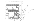
- FIG. 1 is an end view of the operation panel 1000 according to the first embodiment.
- This end view is a view of the end face horizontal to the ground from directly above. Therefore, the front of the paper is the actual upward direction, and the back is the actual downward direction.
- the upper side is the operation side operated by the user, and the lower side is the back side thereof.
- the upper side of the paper surface is referred to as the operation side
- the lower side is referred to as the back side
- the lateral direction of the paper surface is referred to as the right side and the left side as it is.
- the axis extending in the vertical direction of the paper surface is called the central axis
- the one closer to the central axis is called the inner side
- the one farther from the central axis is called the outer side.
- the operation panel 1000 includes a housing 1, a button switch 100, and a cable 7, and outputs that the user presses the button switch 100 to an external device through the cable 7.
- the housing 1 includes a housing body 13 and a metal plate 12.
- the housing body 13 has a rectangular parallelepiped structure with a hollow inside, and has an operation panel 11 facing the operation side.
- the operation panel 11 has a front surface which is an operation surface facing the operation side, and has a back surface on the back side thereof. Further, an opening 16 is provided in which the operation member 2 of the button switch 100 is exposed from the operation side, which will be described later.
- the opening on the back side of the housing body 13 is covered with a plate (not shown). Further, the plate is provided with a hole through which the cable 7 described later passes.
- the metal plate 12 is made of a hard metal (for example, iron) that is not easily deformed or damaged.
- the metal plate 12 has a bent surface 12b whose both ends are bent at right angles toward the back side, and the bent surface 12b is in contact with the inner wall of the side surface of the housing body 13.
- the mounting surface 12a which is the central portion of the metal plate 12 excluding the bent surface 12b, is provided so as to face the back surface of the operation panel 11, and the lateral length is the right side of the inner wall of the side surface of the housing body 13. Matches the length from to the left side.
- the metal plate 12 is fixed to the housing body 13 by fixing the bent surface 12b to the inner wall of the side surface of the housing body 13 with bolts 14 and nuts 15.
- the metal plate 12 is provided with a recess 17 on the operation side of the mounting surface 12a, which is in contact with the convex portion which is the guide portion 42 of the support parts 4a and 4b described later.
- the button switch 100 includes an operation member 2, a button base 3, a support member 40, a screw 5 which is a fixing member, and a substrate member 6.
- the operation member 2 includes a button top 21, an adapter 22, and a movable body 23 in order from the operation side, and moves from the operation side to the back side by a pushing operation of the user.
- the button top 21 is a portion exposed to the operation side from the opening 16 of the housing 1 and touches the user's hand. Further, the button top 21 is a design surface of the button switch 100, and various characters and numbers are written on it.
- the button top 21 has a claw-shaped shape that faces inward on the circumference of the back side, and is coupled to the adapter described below by this claw-shaped shape.
- the adapter 22 connects the button top 21 and the movable body 23.
- the adapter 22 has a recess on the circumference of the operation side for connecting to the claw-shaped shape of the button top 21, and the circumference of the back side has a claw-shaped shape for connecting to the movable body 23 on the outside. It is formed facing.
- the button top 21 manufactured according to different standards can be coupled to other members of the button switch 100.
- the movable body 23 is a member that supports the button top 21 via the adapter 22 and is held by the button base 3 described below so that it can be moved by a pushing operation from the operation side.
- the circumference on the operation side has a claw-shaped shape that is coupled to the claw-shaped shape of the adapter 22 inward.
- a collar is provided on the circumference of the back side toward the outside, and the collar provided on the button base 3 described below suppresses the movement toward the operation side.
- the movable body 23 has a pressing portion, which is a convex portion for pressing the switch 62, which will be described later, in the center thereof.
- the button base 3 holds the operating member 2 so that it can be moved by a pushing operation of the user.
- the length in the lateral direction is smaller than that of the opening 16, and it is formed so that it can be taken out from the opening 16.
- the button base 3 has a collar facing inward on the circumference of the operation side, and suppresses the movement of the operation member 2 including the movable body 23 to the operation side.
- the button base 3 has a plate portion 32 that supports the substrate 61 of the substrate member 6, which will be described later, inside the outer frame having a flange.
- the plate portion 32 has a hole in the center thereof through which the connector 63 of the substrate member 6 penetrates.
- the button base 3 has one claw portion 31 on the left and right sides supported by the support member 40 described later on the back side.
- the claw portion 31 faces the outside of the button base 3, and the hook portion 41 of the support member 40 suppresses the movement to the operation side. Further, the claw portion 31 is inside the outer edge of the operating member 2.
- the support member 40 is composed of support parts 4a and 4b, which are parts smaller than the opening 16.
- the support parts 4a and 4b have the same shape, and in the following description, when it is not necessary to distinguish between the two, they are simply referred to as the support parts 4.
- One support component 4 is provided on the right side and one on the left side.
- the support component 4 has a hook portion 41 that prevents the claw portion 31 of the button base 3 from moving to the operation side.
- the hook portion 41 has a flexible inclined portion 41a inside, and the distance from the operation panel 11 increases toward the inside, and the inclined portion 41a hooks the claw portion 31 of the button base 3.
- the inclined portion 41a is provided at a position facing the gap 81 between the edge of the opening 16 and the outer edge of the operating member 2. Therefore, in the left and right support parts 4, the length between the hook portions 41 provided with the inclined portions 41a inside is longer than the length between the right edge and the left edge of the opening 16.
- the support component 4 has a base portion 43 in contact with the mounting surface 12a, which is the central portion of the metal plate 12.
- the base portion 43 includes a guide portion 42 which is a convex portion that fits into the concave portion 17 provided on the mounting surface 12a of the metal plate 12.
- the screw 5 which is a fixing member passes through the female screw provided on the base portion 43 of the support component 4 and the mounting surface 12a of the metal plate 12, and fixes the support component 4 constituting the support member 40 to the metal plate 12 of the housing 1. It is a thing.
- the head of the screw 5 is provided at a position facing the opening 16. Therefore, by inserting the driver into the opening 16 from the operation side, the fixing and releasing operations can be performed by the screw 5.
- the board member 6 includes a board 61, a switch 62 incorporated in the board 61, a connector 63, and a light source 64.
- the switch 62 is pressed according to the movement of the operation member 2 by the pushing operation of the user, and the fact that the switch 62 is pressed is output from the connector 63 to the external device, and at the same time, the light source 64 is turned on. Further, the light source 64 is turned off according to the signal input from the external device via the connector 63.
- the board 61 is located in the center of the button switch 100 and is supported by the plate portion 32 of the button base 3.
- the switch 62 is incorporated in the center of the operation side, and the light source 64 is incorporated in the right side and the left side of the operation side.
- a connector 63 is provided in the center of the back side.
- the operation side of the switch 62 is in contact with the pressing portion of the movable body 23, and the operation member 2 is pressed by the pushing operation of the user to turn on the switch 62. Further, when the pushing operation of the user is released, the switch 62 pushes the pressing portion back to the operation side by the restoring force, and returns the operation member 2 to the original position.
- the connector 63 is coupled to the mounting connector 71 of the cable 7 described below, and performs input / output of signals and reception of electric power. Further, the light source 64 is an LED (Light Emitting Diode) that emits light by electric power supplied from the outside via the connector 63.
- LED Light Emitting Diode
- the cable 7 mediates the input / output of signals between the button switch 100 and the external device, and supplies electric power to the button switch 100 from the external device.
- the cable 7 includes a mounting connector 71, an electric wire 72, a relay connector 73, and an external connector 74.
- the mounting connector 71 is connected by inserting the connector 63 of the board member 6 from the operation side into the inside.
- the mounting connector 71 has a wide operation side and has a shape that makes it easy to insert the connector 63. Further, the mounting connector 71 is supported by a groove provided inside the support component 4.
- FIG. 2 is a partially enlarged view when the connector 63 is pulled out from the mounting connector 71.
- the connector 63 has a plurality of connector terminals 63a
- the mounting connector 71 has a mounting connector terminal 71a having a one-to-one correspondence with the connector terminal 63a.
- the button switch 100 becomes conductive.
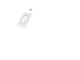
- FIG. 3 is a perspective view of the connector terminal 63a
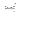
- FIG. 4 is a diagram showing the contacted connector terminal 63a and the mounting connector terminal 71a.
- the connector terminal 63a has a shape that protrudes to the back side and is curved, so that it can be reliably in contact with the mounting connector terminal 71a.
- the electric line 72 is provided with a power line and a signal line.
- the relay connector 73 is provided on the side opposite to the mounting connector 71 of the electric wire 72, and is coupled to the external connector 74.
- the connection between the relay connector 73 and the external connector 74 is removable.
- the relay connector 73 and the external connector 74 are connected by a screw, and can be removed and attached by turning the connecting portion.
- the electric wire 72 connected to the external device from the external connector 74 has a sufficient length, and by pulling the mounting connector 71 from the operation side, the joint portion between the relay connector 73 and the external connector 74 is operated from the opening 16. Can be pulled out to the side.
- the connection between the relay connector 73 and the external connector 74 may be other than a screw. For example, it may be an electrical wiring connector that conducts by fitting.
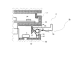
- FIG. 5 is an end view of the operation panel 1000 when the jig 8 is inserted into the gap 81.
- the jig 8 is used for exchanging the button switch 100, and includes a handle 82 and two insertion portions 83 at both ends of the handle 82 facing in the same direction.
- the length of the handle 82 is slightly longer than the width of the button top 21, and the insertion portion 83 intersects the handle 82 at a right angle. Therefore, in the jig 8, if the handle 82 is held horizontally with the button top 21 and the tip of the insertion portion 83 is inserted into the gap 81, two insertion portions 83 can be inserted into the gap 81 at the same time.
- the joint portion between the relay connector 73 of the cable 7 and the external connector 74 can be taken out from the opening 16. Further, at this time, if it is necessary to replace the mounting connector 71, it can be replaced by disengaging the coupling portion of the relay connector 73 and the external connector 74.
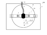
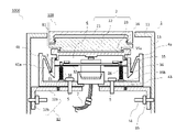
- FIG. 7 is a view of the operation panel 1000 as viewed from the operation side after the button base 3 is removed and the joint portion between the relay connector 73 of the cable 7 and the external connector 74 is taken out from the opening 16.
- the portion shown by the dotted line of the support component 4 represents a portion hidden behind the operation panel 11 and not visible. Further, the filled portion in the center of the metal plate 12 represents a hole through which the cable 7 passes.
- the fixing of the support member 40 by the screw 5 is released.
- This fixing can be released for each of the support parts 4 provided on the left and right.
- the support parts 4 that have been released from the fixing can be removed one by one from the mounting surface 12a of the metal plate 12. That is, the plurality of support parts 4a and 4b constituting the support member 40 are detachably attached to the metal plate 12, and each of the support parts 4 is smaller than the opening 16, so that the support parts 4a and 4b are taken out from the opening 16. Can be done.
- the button switch 100 can be removed from the operation side. Next, a method of attaching the button switch 100 will be described. Installation is performed in the reverse order of removal.
- one support component 4 is inserted through the opening 16 and installed on the mounting surface 12a. At this time, by installing the guide portion 42 so as to come into contact with the recess 17 of the mounting surface 12a, it can be installed at the correct position. Next, the support component 4 is fixed to the mounting surface 12a with a screw 5 using a screwdriver. This is done for both the left and right support parts 4.
- the button switch 100 can be attached by inserting the operation member 2, the button base 3, and the board member 6 through the opening 16.
- the support member 40 that supports the button base 3 on the housing 1 when the support member 40 that supports the button base 3 on the housing 1 is replaced, the support member 40 can be taken out from the operation side. Therefore, the work of opening the housing body 13 itself in order to replace the support member 40 becomes unnecessary. This is particularly useful when work is difficult because the operation panel 1000 is embedded in the wall of a building.
- the button switch 100 in the present embodiment can open and close the operation panel 11 such as the call button installed in the elevator landing and the operation panel 1000 of the destination button installed in the elevator car. It is especially useful for things that are difficult for design reasons and require a lot of effort when working from the back side.
- the support component 4 is guided to a specific installation position even when working from the opening 16 where the work space is limited, so that it is easy to install.
- the support member 40 is divided into a plurality of support parts 4. As a result, although the hooks can be taken out from the opening 16, the lengths of the hooks 41 provided on the left and right are longer than those of the opening 16, and the inclined portions 41a are installed at positions facing the gap 81.
- the tool 8 makes it easy to release the support of the button base 3.
- Embodiment 2 is a button switch 100 provided with a lever 9 for releasing the support of the button base 3 by rotating by pressing the jig 8 instead of the hook portion 41 of the support member 40.
- FIGS. 8, 9, and 10 The same reference numerals as those in FIG. 5 in each drawing represent the same or corresponding parts.
- FIG. 8 is an end view of the operation panel 1000 according to the present embodiment.
- a lever 9 is provided in place of the hook portion 41 in the left and right support parts 4.
- the lever 9 has a jig receiver 96 on the outside of the shaft 91, and the jig receiver 96 is located at a position facing the gap 81.
- FIG. 9 shows in detail the lever 9 of the support component 4 on the right side and its surroundings.
- the lever 9 on the right side will be described.
- the lever 9 has a shaft 91, a lever claw 92, a stopper 93, a torsion coil spring 94, a spring stopper 95, and a jig receiver 96.
- the shaft 91 is fixed to the support component 4, and is provided with a lever claw 92 and a jig receiver 96 at both ends thereof, and a stopper 93 is provided in the back side direction. Further, a torsion coil spring 94 is wound around the shaft 91.
- the lever claw 92 is provided inside the shaft 91, and the back side of the lever claw 92 moves to the operation side of the claw portion 31 of the button base 3 in the same manner as the inner one end of the inclined portion 41a of the first embodiment. It suppresses. That is, the lever claw 92 supports the button base 3 so that the button base 3 does not come off when it comes into contact with the claw portion 31. Further, the operation side of the lever claw 92 pushes the button base 3 toward the operation side by coming into contact with the back side of the button base 3 when the lever 9 rotates clockwise.
- the jig receiver 96 is located at a position facing the gap 81 outside the shaft 91, and moves in the back side direction when pressed by the jig 8.
- the torsion coil spring 94 is wound around the shaft 91, and one end thereof is fixed to the base portion 43 of the support component 4. The other end is hooked from the back side by a spring stopper 95 which is a convex portion provided on the jig receiver 96.
- the torsion coil spring 94 applies a force for counterclockwise rotation about the shaft 91 to the lever 9.
- the lever claw 92 presses the claw portion 31 in the back side direction by the force of counterclockwise rotation by the torsion coil spring 94.
- the stopper 93 is a convex portion provided on the back side of the shaft 91.
- the stopper 93 prevents the lever 9 from rotating counterclockwise beyond a certain angle when the button base 3 is taken out. More specifically, when the button base 3 is taken out, the claw portion 31 of the button base 3 does not suppress the movement of the lever claw 92 in the back side direction. Then, since the lever 9 tends to rotate counterclockwise due to the force of the torsion coil spring 94, the lever 9 is brought into contact with the stopper receiver 44, which is a convex portion provided on the support component 4, to suppress this counterclockwise rotation.
- FIG. 10 is an end view showing the same region as in FIG. 9 when the jig receiver 96 is pressed by the insertion portion 83 of the jig 8.
- the dotted line in the figure represents the position of the lever and the button base 3 before pressing.
- the button base 3 can also be taken out from the opening 16.
- the lever claw 92 tries to continue the counterclockwise rotation by the force of the counterclockwise rotation by the torsion coil spring 94, but the counterclockwise rotation is suppressed by the contact between the stopper 93 and the stopper receiver 44.
- the lever 9 stops rotating at a position that is almost the same as when the button base 3 is supported. That is, when the button switch 100 is attached, if the button base 3 is inserted, the claw portion 31 of the flexible button base 3 is deformed by coming into contact with the operation side of the lever claw 92, and the button base 3 is attached. Can be done.
- the button switch 100 which is hard to break even if the support component 4 is pressed by the jig 8. Further, since the operation side of the lever claw 92 moves the button base 3 to the operation side, the button base 3 can be easily taken out from the opening 16.
- Embodiment 3 is a button switch 100 in which an extension member 34, which is a drive member, is attached to a button base 3.
- an extension member 34 which is a drive member
- FIGS. 11 and 12 the same reference numerals as those in FIG. 5 represent the same or corresponding parts.
- FIG. 11 is an end view of the entire operation panel 1000 according to the present embodiment.
- the button base 3 has an extension member 34 on the plate portion 32.
- the extension member 34 includes a support column 35 and a spring 36, and is in a compressed state when the claw portion 31 of the button base 3 is supported by the inclined portion 41a of the support component 4, and is in an extended state when the support is released. It is something that changes.
- the strut 35 has a rod-shaped structure that passes through a hole provided in the plate portion 32, and has a strut stopper 35a at one end on the operation side and a foot portion 35b at one end on the back side.
- the strut stopper 35a is a member larger than the hole provided in the plate portion 32, and prevents the strut 35 from falling out of the hole.
- the foot portion 35b is a portion in contact with the base portion 43 of the support component 4. Further, the length of the support column 35 is longer than the length from the plate portion 32 to the base portion 43.
- the spring 36 is wound around the support column 35 and applies pressure to the back side of the plate portion 32 and the operation side of the foot portion 35b.
- the winding of the spring 36 is larger than the hole provided in the plate portion 32. Therefore, the spring 36 does not pass through the hole.
- FIG. 12 is an end view of the entire operation panel 1000 according to the present embodiment when the support of the button base 3 is released by the support component 4.
- the length of the support column 35 is longer than the length from the plate portion 32 to the base portion 43, so that a part of the operation side of the support column 35 is provided on the plate portion 32. It exists on the operation side of the plate portion 32 through the formed hole. At this time, since the spring 36 does not pass through the hole, it is pressed by the back side of the plate portion 32 and the operation side of the foot portion 35b. That is, the spring 36 applies a force to the button base 3 to move toward the operation side, which is the direction of the opening 16.
- the operation member 2 protrudes toward the operation side from the opening 16 and the button base 3 can be easily pulled out.
- Embodiment 4 is a button switch 100 provided with a magnet which is a driving member.
- FIG. 13 the same reference numerals as those in FIG. 1 represent the same or corresponding parts. First, the configuration of the present embodiment will be described.
- the portion of the back side of the plate portion 32 that is outside the position facing the screw 5 is thicker than that of the first embodiment.
- a button base magnet 33 is provided on the back side of the thick portion.
- a support component magnet 45 is provided at a position of the base portion 43 facing the button base magnet 33.
- the directions of the magnetic fields of the button base magnet 33 and the support component magnet 45 are such that they repel each other. For example, when the back side of the button base magnet 33 is the S pole, the operation side of the support component magnet 45 is also the S pole.
- the connector magnet 63b is also provided on the back side of the connector 63, and the mounting connector magnet 71b is also provided at a position facing the connector magnet 63b of the mounting connector 71.
- the direction of these magnetic fields is that the connector magnet 63b is the same as the button base magnet 33 and the mounting connector magnet 71b is the same as the support component magnet 45. Therefore, the connector magnet 63b and the mounting connector magnet 71b are oriented so as to repel each other.
- the button base 3 moves to the operation side due to the repulsive force between the magnets. Therefore, the operation member 2 protrudes toward the operation side from the opening 16, and the button base 3 can be easily pulled out.
- Embodiment 5 is a button switch 100 provided with a leaf spring member 52 instead of the hook portion 41 of the support member 40.
- FIGS. 14, 15 and 16 The same reference numerals as those in FIG. 5 in each drawing represent the same or corresponding parts.
- FIG. 14 is an end view of the operation panel 1000 according to the present embodiment.
- a leaf spring member 52 is provided instead of the hook portion 41. That is, in the present embodiment, the left and right support parts 4 include a leaf spring member 52 and a base portion 43.
- the support component 4b on the left side will be described.
- the leaf spring member 52 has a leaf spring claw 52a, a jig receiver 52b, a pillar portion 52c, a deforming portion 52d, a base pressing portion 52e, and a jig guide 52f, which are inclined portions, and the deforming portion 52d is a screw 51. It is fixed to the base portion 43 of the support component 4 by the support component 4. Further, the base portion 43 of the support component 4 in the present embodiment has a pressing support portion 46.
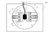
- FIG. 15 is a view of the operation panel 1000 as viewed from the operation side after the button base 3 is removed.
- the portion shown by the dotted line of the support component 4 represents a portion hidden behind the operation panel 11 and not visible.
- the leaf spring member 52 has one deformed portion 52d in the vertical direction of the paper surface so as to sandwich the pressing support portion 46 of the base portion 43 to be described later. Further, one end inside each of the deformed portions 52d is fixed to a portion other than the pressing support portion 46 of the base portion 43 by a screw 51. Further, the outer end of the two deformed portions 52d is integrated via the back end of the pillar portion 52c, which will be described later.
- the vertical direction of the paper surface is the vertical direction when the operation panel 1000 is actually viewed from the operation side.
- the pressing support portion 46 of the base portion 43 is provided at the center of the base portion 43 in the vertical direction of the paper surface, and protrudes to the outside of the base portion 43 between the deformed portions 52d provided one by one in the vertical direction of the paper surface. It is a portion and is located on the back side of the base pressing portion 52e as shown in FIG.
- the configuration of the leaf spring member 52 will be described in detail.
- the pillar portion 52c is a pillar extending in the moving direction of the operating member 2.
- One end of the back side of the pillar portion 52c is sandwiched between two deformed portions 52d, and has a base pressing portion 52e inside.
- the operation side of the pillar portion 52c has a leaf spring claw 52a, a jig receiver 52b, and a jig guide 52f.
- the base pressing portion 52e has a structure that is sandwiched between two deforming portions 52d and extends inward from one end on the back side of the pillar portion 52c, and the inner end is between the button base 3 and the pressing support portion 46. It forms a convex part that is bent to the side.
- the jig receiver 52b has a structure extending inward from one end of the pillar portion 52c on the operation side, and is provided at a position facing the gap 81.
- the jig guide 52f is two pillars provided at both inner and outer ends of the jig receiver 52b, and is a pillar extending in the moving direction of the operating member 2 like the pillar portion 52c.
- the leaf spring claw 52a is a claw provided at one end of the inner jig guide 52f on the operation side. The inner end of the leaf spring claw 52a suppresses the movement of the claw portion 31 of the button base 3 toward the operation side, similarly to the inner end of the inclined portion 41a of the first embodiment.
- FIG. 16 is an end view showing the same region as in FIG. 14 when the jig receiver 52b is pressed by the insertion portion 83 of the jig 8.
- the portion of the left leaf spring member 52 other than the deformed portion 52d rotates counterclockwise around the outer end of the pressing support portion 46.
- the deforming portion 52d is deformed by the pressure pressed by the insertion portion 83.
- the contact between the leaf spring claw 52a and the claw portion 31 is released, and the base pressing portion 52e moves the button base 3 to the operation side.
- the button base 3 can also be taken out from the opening 16. Further, when the pressing by the inserting portion 83 is stopped, the deformation of the deformed portion 52d is released and the original shape is restored.
- the fixing of the leaf spring member 52 to the base portion 43 is released. Since the leaf spring member 52 is smaller than the opening 16, the leaf spring member 52 whose fixing has been released can be taken out one by one from the opening 16.
- the base portion 43 can also be taken out by the same operation as in the first embodiment.
- the button switch 100 can be taken out from the opening 16 as in the other embodiments.
- the leaf spring member 52 can also be taken out from the opening 16.
- the leaf spring member 52 can be manufactured at a lower cost than the lever 9 of the second embodiment.
- the jig guide 52f is provided, the jig 8 can easily press the jig receiver 52b.
- the leaf spring member 52 may be manufactured by deforming one metal plate.
- the operation member 2 and the button base 3 are composed of different parts, but the operation member 2 and the button base 3 may be composed of one integrated component. Further, the operating member 2 is moved from the operating side to the back side by a pushing operation from the user, but in order to solve the problem, the operating member 2 may be operated by the user from the operating side. Anything will do.
- the operating member 2 may be a touch panel
- the button switch 100 may be a touch-type button
- the operating member 2 may be a non-contact sensor
- the button switch 100 may be a non-contact button.
- the support member 40 is composed of a support component 4 smaller than the opening 16.
- the term smaller than the opening 16 here means that the size is such that it can pass through the opening 16 when it is taken out.
- the support component 4 may be provided with a bending mechanism so that it can be deformed inside the housing 1 to a size that can be taken out from the opening 16.
- the support member 40 is composed of two support parts 4, but the structure of the parts is not limited to this, and may be composed of a plurality of three or more parts. Further, in the first embodiment, the support member 40 is composed of a plurality of support parts 4 in order to make the inclined portion 41a face the gap 81, but in order to solve the problem, the support member 40 is used. It may be one member smaller than the opening 16.
- the fixing member is a screw 5, but the fixing member may be any as long as it can release the fixing of the support member 40 by an operation from the operation side, for example, a pin or the like. Further, the fixing member may be a support member 40, a claw provided on the metal plate 12, or the like.
- the spring 36 and the torsion coil spring 94 in the embodiment another elastic body such as rubber may be used as long as it has the same function.
- the guide portion 42 is a convex portion, but the guide portion 42 may be made a concave portion and a convex portion may be provided on the base portion 43.
- the directions of the magnetic fields of the magnets which are the driving devices, repel each other, but the directions are attracted to each other, and as a guide for installing the button base 3 in the correct position when inserting the button base 3. May be good. That is, a force that causes the button base 3 to move from the opening 16 toward the inside of the housing 1 may be applied to the button base 3. Further, by electrically controlling the direction of the magnetic field of the magnet and inverting the magnetic field, the magnetic field is set in the direction in which the magnets repel each other when the button base 3 is taken out, and when the button base 3 is attached, the magnets move with each other. The magnetic field may be set in the direction of attraction.
- the button switch 100 is supplied with electric power via the cable 7, but in order to solve the problem, the button switch 100 is powered by using wireless power feeding technology instead of the cable 7. May be supplied. That is, the button switch 100 may include a receiver for a wireless power supply system. Further, instead of the cable 7, a wireless communication device may be provided to input / output signals to / from an external device.
- the support member 40 is deformed by being pressed by the jig 8 from the operation side, and the support of the button base 3 is released.
- the support of the button base 3 may be released by another method.
- the button switch 100 may be provided with a receiving device for receiving a release command by remote control from the outside of the housing 1. That is, when the receiving device receives the release command for releasing the support of the button base 3 by the support member 40, the support member 40 deforms the inclined portion 41a and the lever 9 supporting the button base 3 to deform the button base. The support of 3 may be released. Similarly, the support member 40 may be released from being fixed by the fixing member by remote control.
- the support component magnet 45 of the fourth embodiment is attached to the support components 4a and 4b provided with the lever 9 of the second embodiment. May be good.
Landscapes
- Push-Button Switches (AREA)
Abstract
Description
以下に実施の形態1にかかるボタンスイッチ100及び操作盤1000を図面に基づいて詳細に説明する。なお、各図面における同一の符号は同一又は相当の構成を表している。
The
本実施の形態は、支持部材40の鉤部41の代わりに、治具8の押圧により回転することで、ボタンベース3の支持を解除するレバー9を設けたボタンスイッチ100である。以下、図8、図9、及び図10を用いて、実施の形態1との相違点を中心に説明する。各図面における図5と同一の符号は、同一又は相当の部分を表している。
The present embodiment is a
本実施の形態は、ボタンベース3に駆動部材である伸長部材34を取り付けたボタンスイッチ100である。以下、図11及び図12を用いて実施の形態1との相違点を中心に説明する。図11及び図12において、図5と同一の符号は同一又は相当の部分を表している。初めに本実施の形態の構成について、図11を用いて説明する。図11は本実施の形態に係る操作盤1000全体の端面図である。
The present embodiment is a
本実施の形態は、駆動部材である磁石を備えたボタンスイッチ100である。以下、図13を用いて実施の形態1との相違点を中心に説明する。図13において、図1と同一の符号は同一又は相当の部分を表している。初めに、本実施の形態の構成について説明する。 Embodiment 4.
The present embodiment is a
本実施の形態は、支持部材40の鉤部41の代わりに板バネ部材52を設けたボタンスイッチ100である。以下、図14、図15及び図16を用いて、実施の形態1との相違点を中心に説明する。各図面における図5と同一の符号は、同一又は、相当の部分を表している。
The present embodiment is a
Claims (12)
- 開口が設けられた操作盤の操作を行う操作側から利用者により操作される操作部材と、
前記開口から挿入可能に形成され、前記操作部材を保持するボタンベースと、
前記開口よりも小さい部品で構成され、前記操作側からの操作により前記ボタンベースを外せるように前記ボタンベースを支持する支持部材と、
前記開口から操作可能な位置に設けられ、前記支持部材を前記操作盤の筺体に固定する固定部材と、
を備えたボタンスイッチ。 An operation member operated by the user from the operation side that operates the operation panel provided with the opening, and
A button base that is formed so that it can be inserted through the opening and holds the operating member,
A support member that is composed of parts smaller than the opening and supports the button base so that the button base can be removed by an operation from the operation side.
A fixing member provided at a position operable from the opening and fixing the support member to the housing of the operation panel, and a fixing member.
Button switch with. - 前記固定部材は、ねじであり、前記ねじの頭部が前記開口と対向する位置にあることを特徴とする請求項1に記載のボタンスイッチ。 The button switch according to claim 1, wherein the fixing member is a screw, and the head of the screw is at a position facing the opening.
- 前記支持部材は、前記開口を介して前記筺体内から別々に取り出し可能な複数の前記部品により構成されていることを特徴とする請求項1又は2に記載のボタンスイッチ。 The button switch according to claim 1 or 2, wherein the support member is composed of a plurality of the parts that can be separately taken out from the housing through the opening.
- 前記支持部材は傾斜部を有し、この傾斜部で前記ボタンベースを引っ掛け、
前記支持部材は、前記筺体に固定された状態において、前記開口と前記操作部材との隙間と対向する位置に設けられ、可撓性を有することを特徴とする請求項1から3のいずれか一つに記載のボタンスイッチ。 The support member has an inclined portion, and the button base is hooked on the inclined portion.
One of claims 1 to 3, wherein the support member is provided at a position facing the gap between the opening and the operation member in a state of being fixed to the housing, and has flexibility. The button switch described in one. - 前記ボタンベースは爪部を備え、
前記支持部材は、一端と他端の間に設けられた軸を中心に回転するレバーを備え、前記レバーは、前記一端が前記爪部と接触することにより前記ボタンベースが抜けないように前記ボタンベースを支え、前記他端が押され前記軸を中心に回転することで前記爪部との接触が解除される
ことを特徴とする請求項1から3のいずれか一つに記載のボタンスイッチ。 The button base has a claw and
The support member includes a lever that rotates about a shaft provided between one end and the other end, and the lever is such that the button base does not come off when the one end comes into contact with the claw portion. The button switch according to any one of claims 1 to 3, wherein the other end of the base is supported and the other end is pushed and rotated about the shaft to release the contact with the claw portion. - 前記支持部材は前記筺体における取付面に設けられた凹部又は凸部と接触することにより、前記取付面における特定の位置に前記支持部材を誘導するガイド部を備えたことを特徴とする請求項1から5のいずれか一つに記載のボタンスイッチ。 Claim 1 is characterized in that the support member is provided with a guide portion for guiding the support member to a specific position on the mounting surface by coming into contact with a concave portion or a convex portion provided on the mounting surface of the housing. The button switch according to any one of 5 to 5.
- 前記ボタンベースが前記筺体の内部から前記開口の方向に移動する力を前記ボタンベースに加える駆動部材を備えたことを特徴とする請求項1から6のいずれか一つに記載のボタンスイッチ。 The button switch according to any one of claims 1 to 6, wherein the button base includes a driving member that applies a force for moving the button base from the inside of the housing toward the opening to the button base.
- 前記ボタンベースが前記開口から前記筺体の内部の方向に移動する力を前記ボタンベースに加える駆動部材を備えたことを特徴とする請求項1から7のいずれか一つに記載のボタンスイッチ。 The button switch according to any one of claims 1 to 7, wherein the button base includes a driving member that applies a force for moving the button base from the opening toward the inside of the housing to the button base.
- 前記支持部材による前記ボタンベースの支持を解除する解除命令を受信する受信装置をさらに備え、
前記支持部材は前記受信装置が前記解除命令を受信した場合に、前記ボタンベースの支持を解除することを特徴とする請求項1から8のいずれか一つに記載のボタンスイッチ。 Further comprising a receiving device for receiving a release command to release the support of the button base by the support member.
The button switch according to any one of claims 1 to 8, wherein the support member releases the support of the button base when the receiving device receives the release command. - 無線給電システムのレシーバーを備えたことを特徴とする請求項1から9のいずれか一つに記載のボタンスイッチ。 The button switch according to any one of claims 1 to 9, wherein the receiver is provided with a wireless power supply system.
- 操作面である表面と裏面とを有し開口が設けられた操作パネル、及びこの操作パネルの裏面に対向するように設けられた金属板を備えた筺体と、
前記開口から露出し、前記操作面側から利用者により操作される操作部材、
前記開口から前記筺体内に挿入可能に形成され、前記操作部材を保持するボタンベース、
前記開口よりも小さい部品で構成され、前記開口と前記操作部材との間の隙間から挿入された治具により前記ボタンベースを外せるように前記ボタンベースを支持する支持部材、及び
前記操作面側から操作可能な位置に設けられ、前記支持部材を前記筺体の前記金属板に固定する固定部材、
を備えたボタンスイッチと、
を備えた操作盤。 An operation panel having an opening having a front surface and a back surface, which are operation surfaces, and a housing provided with a metal plate provided so as to face the back surface of the operation panel.
An operating member exposed from the opening and operated by the user from the operating surface side.
A button base, which is formed so as to be inserted into the housing through the opening and holds the operating member.
From the support member that is composed of parts smaller than the opening and supports the button base so that the button base can be removed by a jig inserted from the gap between the opening and the operation member, and from the operation surface side. A fixing member provided at an operable position and fixing the support member to the metal plate of the housing.
With a button switch and
Operation panel equipped with. - ボタントップを有する操作部材と、前記操作部材を保持するボタンベースと、前記ボタンベースを支持し、固定部材により操作盤の筺体に固定された支持部材とを備えたボタンスイッチを前記筺体から取り外す方法であって、
前記ボタントップと前記操作盤の開口の縁との隙間に治具を挿入し、前記ボタンベースの前記支持部材による支持を解除するステップと、
前記操作部材及び前記ボタンベースを前記操作盤の前記開口から取り出すステップと、
前記支持部材を前記操作盤の前記筺体に固定している前記固定部材を前記開口から操作し、前記固定部材による前記支持部材の固定を解除するステップと、
前記支持部材を前記開口から取り出すステップと、
を備えたボタンスイッチの取外し方法。 A method of removing a button switch having an operation member having a button top, a button base for holding the operation member, and a support member that supports the button base and is fixed to the housing of the operation panel by a fixing member from the housing. And,
A step of inserting a jig into the gap between the button top and the edge of the opening of the operation panel to release the support of the button base by the support member.
A step of taking out the operation member and the button base from the opening of the operation panel,
A step of operating the fixing member for fixing the support member to the housing of the operation panel from the opening and releasing the fixing of the support member by the fixing member.
The step of taking out the support member from the opening and
How to remove the button switch equipped with.
Priority Applications (3)
| Application Number | Priority Date | Filing Date | Title |
|---|---|---|---|
| JP2022563532A JP7338802B2 (en) | 2020-11-20 | 2020-11-20 | How to remove the button switch, operation panel, and button switch |
| CN202080107150.6A CN116490947A (en) | 2020-11-20 | 2020-11-20 | Push button switch, operation panel, and method for removing push button switch |
| PCT/JP2020/043443 WO2022107322A1 (en) | 2020-11-20 | 2020-11-20 | Button switch, operating panel, and method for removing button switch |
Applications Claiming Priority (1)
| Application Number | Priority Date | Filing Date | Title |
|---|---|---|---|
| PCT/JP2020/043443 WO2022107322A1 (en) | 2020-11-20 | 2020-11-20 | Button switch, operating panel, and method for removing button switch |
Publications (1)
| Publication Number | Publication Date |
|---|---|
| WO2022107322A1 true WO2022107322A1 (en) | 2022-05-27 |
Family
ID=81708685
Family Applications (1)
| Application Number | Title | Priority Date | Filing Date |
|---|---|---|---|
| PCT/JP2020/043443 WO2022107322A1 (en) | 2020-11-20 | 2020-11-20 | Button switch, operating panel, and method for removing button switch |
Country Status (3)
| Country | Link |
|---|---|
| JP (1) | JP7338802B2 (en) |
| CN (1) | CN116490947A (en) |
| WO (1) | WO2022107322A1 (en) |
Cited By (1)
| Publication number | Priority date | Publication date | Assignee | Title |
|---|---|---|---|---|
| WO2024084946A1 (en) * | 2022-10-21 | 2024-04-25 | 株式会社ソニー・インタラクティブエンタテインメント | Input device and operating button |
Citations (4)
| Publication number | Priority date | Publication date | Assignee | Title |
|---|---|---|---|---|
| JPS61129237U (en) * | 1985-01-31 | 1986-08-13 | ||
| JP2002056741A (en) * | 2000-08-09 | 2002-02-22 | Ricoh Co Ltd | Operation button support structure of electronic equipment or the like |
| JP2006318848A (en) * | 2005-05-16 | 2006-11-24 | Sony Corp | Attachable and detachable type mounting component and electronic apparatus |
| JP2018181509A (en) * | 2017-04-07 | 2018-11-15 | 株式会社イガラシコーカ | Operation button unit, control board for lift, and maintenance method |
-
2020
- 2020-11-20 WO PCT/JP2020/043443 patent/WO2022107322A1/en active Application Filing
- 2020-11-20 JP JP2022563532A patent/JP7338802B2/en active Active
- 2020-11-20 CN CN202080107150.6A patent/CN116490947A/en active Pending
Patent Citations (4)
| Publication number | Priority date | Publication date | Assignee | Title |
|---|---|---|---|---|
| JPS61129237U (en) * | 1985-01-31 | 1986-08-13 | ||
| JP2002056741A (en) * | 2000-08-09 | 2002-02-22 | Ricoh Co Ltd | Operation button support structure of electronic equipment or the like |
| JP2006318848A (en) * | 2005-05-16 | 2006-11-24 | Sony Corp | Attachable and detachable type mounting component and electronic apparatus |
| JP2018181509A (en) * | 2017-04-07 | 2018-11-15 | 株式会社イガラシコーカ | Operation button unit, control board for lift, and maintenance method |
Cited By (1)
| Publication number | Priority date | Publication date | Assignee | Title |
|---|---|---|---|---|
| WO2024084946A1 (en) * | 2022-10-21 | 2024-04-25 | 株式会社ソニー・インタラクティブエンタテインメント | Input device and operating button |
Also Published As
| Publication number | Publication date |
|---|---|
| JP7338802B2 (en) | 2023-09-05 |
| JPWO2022107322A1 (en) | 2022-05-27 |
| CN116490947A (en) | 2023-07-25 |
Similar Documents
| Publication | Publication Date | Title |
|---|---|---|
| US7790984B2 (en) | Apparatus for controlling cable of robot | |
| JP5496718B2 (en) | Coil positioning and holding device for non-contact power feeding device | |
| WO2022107322A1 (en) | Button switch, operating panel, and method for removing button switch | |
| JP2014227758A (en) | Handle device for vehicle | |
| CN110362161B (en) | Plug-in device, case adopting plug-in device and electronic device | |
| KR20020080766A (en) | Apparatus for connecting power used magnetic | |
| US11639003B2 (en) | Teaching device and robot system | |
| WO2002016199A1 (en) | Installation device | |
| CN111988929B (en) | Mounting/dismounting structure, connector and electrical equipment | |
| US20230360834A1 (en) | Vehicle-mounted apparatus | |
| CN111050054A (en) | Shielding mechanism, intelligent electronic product and camera shielding control method | |
| US20210138664A1 (en) | Tool adapter for manipulating commercial tools with a robot hand | |
| JPS624510B2 (en) | ||
| CN115206183B (en) | Electronic equipment | |
| KR200482627Y1 (en) | Device for proventing damage of car door | |
| US11899504B2 (en) | Electronic device | |
| CN103887092A (en) | Electrical switch arrangement and device for controlling an apparatus comprising such an arrangement | |
| JP4685121B2 (en) | Noise current absorber | |
| JP4113719B2 (en) | Noise current absorber | |
| CN211250089U (en) | Mechanical arm, tail end driving structure thereof and robot | |
| JP2021070081A (en) | Striatum support device, robot and robot system | |
| CN210563855U (en) | Lock and vehicle with same | |
| JP2002234675A (en) | Elevator maintenance device | |
| KR102479169B1 (en) | Control Unit of Load Handling Device | |
| CN214589344U (en) | Electric connector and scooter |
Legal Events
| Date | Code | Title | Description |
|---|---|---|---|
| 121 | Ep: the epo has been informed by wipo that ep was designated in this application |
Ref document number: 20962484 Country of ref document: EP Kind code of ref document: A1 |
|
| ENP | Entry into the national phase |
Ref document number: 2022563532 Country of ref document: JP Kind code of ref document: A |
|
| WWE | Wipo information: entry into national phase |
Ref document number: 202080107150.6 Country of ref document: CN |
|
| NENP | Non-entry into the national phase |
Ref country code: DE |
|
| 122 | Ep: pct application non-entry in european phase |
Ref document number: 20962484 Country of ref document: EP Kind code of ref document: A1 |