WO2022102598A1 - Glass substrate - Google Patents

Glass substrate Download PDF

Info

Publication number
WO2022102598A1
WO2022102598A1 PCT/JP2021/041107 JP2021041107W WO2022102598A1 WO 2022102598 A1 WO2022102598 A1 WO 2022102598A1 JP 2021041107 W JP2021041107 W JP 2021041107W WO 2022102598 A1 WO2022102598 A1 WO 2022102598A1
Authority
WO
WIPO (PCT)
Prior art keywords
glass substrate
less
glass
hole
etching
Prior art date
Application number
PCT/JP2021/041107
Other languages
French (fr)
Japanese (ja)
Inventor
雅貴 牧田
Original Assignee
日本電気硝子株式会社
Priority date (The priority date is an assumption and is not a legal conclusion. Google has not performed a legal analysis and makes no representation as to the accuracy of the date listed.)
Filing date
Publication date
Application filed by 日本電気硝子株式会社 filed Critical 日本電気硝子株式会社
Priority to JP2022561926A priority Critical patent/JPWO2022102598A1/ja
Priority to KR1020237018190A priority patent/KR20230098828A/en
Priority to US18/033,475 priority patent/US20230399253A1/en
Priority to CN202180071873.XA priority patent/CN116490476A/en
Publication of WO2022102598A1 publication Critical patent/WO2022102598A1/en

Links

Images

Classifications

    • CCHEMISTRY; METALLURGY
    • C03GLASS; MINERAL OR SLAG WOOL
    • C03CCHEMICAL COMPOSITION OF GLASSES, GLAZES OR VITREOUS ENAMELS; SURFACE TREATMENT OF GLASS; SURFACE TREATMENT OF FIBRES OR FILAMENTS MADE FROM GLASS, MINERALS OR SLAGS; JOINING GLASS TO GLASS OR OTHER MATERIALS
    • C03C3/00Glass compositions
    • C03C3/04Glass compositions containing silica
    • C03C3/076Glass compositions containing silica with 40% to 90% silica, by weight
    • C03C3/083Glass compositions containing silica with 40% to 90% silica, by weight containing aluminium oxide or an iron compound
    • CCHEMISTRY; METALLURGY
    • C03GLASS; MINERAL OR SLAG WOOL
    • C03CCHEMICAL COMPOSITION OF GLASSES, GLAZES OR VITREOUS ENAMELS; SURFACE TREATMENT OF GLASS; SURFACE TREATMENT OF FIBRES OR FILAMENTS MADE FROM GLASS, MINERALS OR SLAGS; JOINING GLASS TO GLASS OR OTHER MATERIALS
    • C03C15/00Surface treatment of glass, not in the form of fibres or filaments, by etching
    • CCHEMISTRY; METALLURGY
    • C03GLASS; MINERAL OR SLAG WOOL
    • C03CCHEMICAL COMPOSITION OF GLASSES, GLAZES OR VITREOUS ENAMELS; SURFACE TREATMENT OF GLASS; SURFACE TREATMENT OF FIBRES OR FILAMENTS MADE FROM GLASS, MINERALS OR SLAGS; JOINING GLASS TO GLASS OR OTHER MATERIALS
    • C03C3/00Glass compositions
    • C03C3/04Glass compositions containing silica
    • C03C3/076Glass compositions containing silica with 40% to 90% silica, by weight
    • C03C3/11Glass compositions containing silica with 40% to 90% silica, by weight containing halogen or nitrogen
    • C03C3/112Glass compositions containing silica with 40% to 90% silica, by weight containing halogen or nitrogen containing fluorine
    • C03C3/115Glass compositions containing silica with 40% to 90% silica, by weight containing halogen or nitrogen containing fluorine containing boron
    • C03C3/118Glass compositions containing silica with 40% to 90% silica, by weight containing halogen or nitrogen containing fluorine containing boron containing aluminium
    • CCHEMISTRY; METALLURGY
    • C03GLASS; MINERAL OR SLAG WOOL
    • C03CCHEMICAL COMPOSITION OF GLASSES, GLAZES OR VITREOUS ENAMELS; SURFACE TREATMENT OF GLASS; SURFACE TREATMENT OF FIBRES OR FILAMENTS MADE FROM GLASS, MINERALS OR SLAGS; JOINING GLASS TO GLASS OR OTHER MATERIALS
    • C03C3/00Glass compositions
    • C03C3/04Glass compositions containing silica
    • C03C3/076Glass compositions containing silica with 40% to 90% silica, by weight
    • C03C3/083Glass compositions containing silica with 40% to 90% silica, by weight containing aluminium oxide or an iron compound
    • C03C3/085Glass compositions containing silica with 40% to 90% silica, by weight containing aluminium oxide or an iron compound containing an oxide of a divalent metal
    • C03C3/087Glass compositions containing silica with 40% to 90% silica, by weight containing aluminium oxide or an iron compound containing an oxide of a divalent metal containing calcium oxide, e.g. common sheet or container glass
    • CCHEMISTRY; METALLURGY
    • C03GLASS; MINERAL OR SLAG WOOL
    • C03CCHEMICAL COMPOSITION OF GLASSES, GLAZES OR VITREOUS ENAMELS; SURFACE TREATMENT OF GLASS; SURFACE TREATMENT OF FIBRES OR FILAMENTS MADE FROM GLASS, MINERALS OR SLAGS; JOINING GLASS TO GLASS OR OTHER MATERIALS
    • C03C3/00Glass compositions
    • C03C3/04Glass compositions containing silica
    • C03C3/076Glass compositions containing silica with 40% to 90% silica, by weight
    • C03C3/089Glass compositions containing silica with 40% to 90% silica, by weight containing boron
    • C03C3/091Glass compositions containing silica with 40% to 90% silica, by weight containing boron containing aluminium
    • GPHYSICS
    • G09EDUCATION; CRYPTOGRAPHY; DISPLAY; ADVERTISING; SEALS
    • G09FDISPLAYING; ADVERTISING; SIGNS; LABELS OR NAME-PLATES; SEALS
    • G09F9/00Indicating arrangements for variable information in which the information is built-up on a support by selection or combination of individual elements
    • G09F9/30Indicating arrangements for variable information in which the information is built-up on a support by selection or combination of individual elements in which the desired character or characters are formed by combining individual elements
    • HELECTRICITY
    • H01ELECTRIC ELEMENTS
    • H01LSEMICONDUCTOR DEVICES NOT COVERED BY CLASS H10
    • H01L21/00Processes or apparatus adapted for the manufacture or treatment of semiconductor or solid state devices or of parts thereof
    • H01L21/02Manufacture or treatment of semiconductor devices or of parts thereof
    • H01L21/04Manufacture or treatment of semiconductor devices or of parts thereof the devices having at least one potential-jump barrier or surface barrier, e.g. PN junction, depletion layer or carrier concentration layer
    • H01L21/48Manufacture or treatment of parts, e.g. containers, prior to assembly of the devices, using processes not provided for in a single one of the subgroups H01L21/06 - H01L21/326
    • H01L21/4814Conductive parts
    • H01L21/4846Leads on or in insulating or insulated substrates, e.g. metallisation
    • H01L21/486Via connections through the substrate with or without pins
    • HELECTRICITY
    • H01ELECTRIC ELEMENTS
    • H01LSEMICONDUCTOR DEVICES NOT COVERED BY CLASS H10
    • H01L23/00Details of semiconductor or other solid state devices
    • H01L23/12Mountings, e.g. non-detachable insulating substrates
    • H01L23/14Mountings, e.g. non-detachable insulating substrates characterised by the material or its electrical properties
    • H01L23/15Ceramic or glass substrates
    • HELECTRICITY
    • H01ELECTRIC ELEMENTS
    • H01LSEMICONDUCTOR DEVICES NOT COVERED BY CLASS H10
    • H01L23/00Details of semiconductor or other solid state devices
    • H01L23/48Arrangements for conducting electric current to or from the solid state body in operation, e.g. leads, terminal arrangements ; Selection of materials therefor
    • H01L23/488Arrangements for conducting electric current to or from the solid state body in operation, e.g. leads, terminal arrangements ; Selection of materials therefor consisting of soldered or bonded constructions
    • H01L23/498Leads, i.e. metallisations or lead-frames on insulating substrates, e.g. chip carriers
    • H01L23/49827Via connections through the substrates, e.g. pins going through the substrate, coaxial cables

Definitions

  • the wiring density increases at the same time, and it is important to reduce the taper angle of the through hole.
  • the taper angle of the through hole is determined by the ratio of the expansion speed of the hole in the plate thickness direction at the time of etching and the expansion speed of the hole diameter. Then, by slowing down the expansion speed of the hole diameter, the taper angle can be reduced.
  • the expansion speed of the pore diameter is synonymous with the HF etching rate of the mother glass. Therefore, it is important to reduce the HF etching rate in order to produce a through hole having a small taper angle. Then, in order to lower the HF etching rate, the content of SiO 2 in the glass composition may be increased.
  • the amount of residue generated during etching is reduced, the residue is less likely to be clogged in the etching apparatus, the load when processing the residue is reduced, and it is necessary for the treatment of the residue. Cost is reduced.
  • the content of SiO 2 is 69.7% or more, the above-mentioned effect is increased, the HF etching rate is lowered, and the taper angle of the through hole can be reduced.
  • the content of SiO 2 is too high, the high-temperature viscosity becomes high, the amount of heat required for melting increases, the melting cost rises, and the raw material introduced into SiO 2 remains undissolved, resulting in a decrease in yield.
  • the upper limit of B 2 O 3 is 15.0%, more preferably 10.0%, more preferably 7.5%, more preferably 7.4%, more preferably 7.3%, and more. It is preferably 7.0%, more preferably 6.5%, more preferably 6.0%, more preferably 5.5%, and particularly preferably 5.0%.
  • Fe 2 O 3 is a component that is inevitably mixed from the glass raw material and is a component that colors the glass. If the content of Fe 2 O 3 is too small, the raw material cost tends to rise. On the other hand, if the content of Fe 2 O 3 is too large, the glass substrate is colored and it becomes difficult to use it for display applications.
  • the content of Fe 2 O 3 is preferably 0 to 300 mass ppm, more preferably 80 to 250 mass ppm, and particularly preferably 100 to 200 mass ppm.
  • the glass substrate of the present invention preferably has the following characteristics.
  • the Young's modulus is preferably 65 GPa or more, more preferably 70 GPa or more, more preferably 75 GPa or more, more preferably 77 GPa or more, and particularly preferably 78 GPa or more. If Young's modulus is too low, problems due to bending of the glass substrate are likely to occur.
  • the liquid phase temperature is preferably 1350 ° C. or lower, more preferably less than 1350 ° C., more preferably 1300 ° C. or lower, and particularly preferably 1000 to 1280 ° C. By doing so, it becomes easy to prevent a situation in which devitrified crystals are generated during molding and productivity is lowered. Further, since it is easy to mold by the overflow down draw method, it is easy to improve the surface quality of the glass substrate and it is possible to reduce the manufacturing cost of the glass substrate.
  • the liquidus temperature is an index of devitrification resistance, and the lower the liquidus temperature, the better the devitrification resistance.
  • phase separation was evaluated as " ⁇ " when no white turbidity was visually confirmed on the glass substrate and " ⁇ " when white turbidity was confirmed.
  • the temperature at the high temperature viscosity of 10 4.0 dPa ⁇ s, 10 3.0 dPa ⁇ s, and 10 2.5 dPa ⁇ s is a value measured by the platinum ball pulling method.
  • sample No. for 1, 4 to 5, 8 to 10, 24 to 43 fine holes were prepared by the following method, and the taper angle of the holes was confirmed.
  • a mixed acid of 2.5 mL / L HF and 1.0 mol / L HCl solution was used as the etching solution, and the temperature of the etching solution was set to 30 ° C. Further, in order to prevent the temperature from rising during the application of ultrasonic waves, the water in the ultrasonic device was circulated using a chiller to keep the water temperature at 30 ° C. An ultrasonic cleaner (VS-100III: manufactured by AS ONE) was used to apply the ultrasonic vibration. As a result, 28 kHz ultrasonic waves were applied to the etching solution.
  • VS-100III manufactured by AS ONE

Abstract

A glass substrate of the present invention comprises, as a glass composition in mol%: SiO2 65.0 to 80.0%; Al2O3 2.0 to 15.0%; B2O3 0 to 15.0%; Li2O + Na2O + K2O 0.001 to less than 0.1%; MgO 0 to 15.0%; CaO 0 to 15.0%; SrO 0 to 15.0%; BaO 0 to 15.0%; SnO2 0.01 to 1.0%; As2O3 0 to less than 0.050%; and Sb2O3 0 to less than 0.050%.

Description

ガラス基板Glass substrate
 本発明はガラス基板に関し、特にマイクロLEDディスプレイに好適なガラス基板に関する。 The present invention relates to a glass substrate, and particularly to a glass substrate suitable for a micro LED display.
 タイリング方式のマイクロLEDディスプレイが開発されている(特許文献1参照)。このディスプレイでは、発光素子としてマイクロLEDを用いた表示パネルを複数枚並べることで一枚のディスプレイを構成している。 A tiling type micro LED display has been developed (see Patent Document 1). In this display, one display is formed by arranging a plurality of display panels using micro LEDs as light emitting elements.
 タイリング方式のマイクロLEDディスプレイでは、タイル同士の境目を視認し難くする必要がある。そのため、従来のディスプレイのように、ガラス基板の周辺部に駆動部を配置することができない。よって、各タイル上の発光素子はガラス裏面側から駆動させる必要があり、この場合、ガラス基板の板厚方向に貫通孔を作製して、ガラス基板の表裏面の導通を取る必要がある。 In the tiling type micro LED display, it is necessary to make it difficult to see the boundary between tiles. Therefore, unlike the conventional display, the drive unit cannot be arranged in the peripheral portion of the glass substrate. Therefore, it is necessary to drive the light emitting element on each tile from the back surface side of the glass, and in this case, it is necessary to create a through hole in the plate thickness direction of the glass substrate to make the front and back surfaces of the glass substrate conductive.
 ガラス基板の板厚方向に貫通孔を作製する方法として、例えばレーザー光の照射によりガラス基板の内部に改質部を作製した後、HFエッチングにより改質部を除去することにより、貫通孔を形成する方法が知られている(特許文献2参照)。この方法で作製された貫通孔は断面視でテーパー形状になる。 As a method of forming a through hole in the plate thickness direction of a glass substrate, for example, a through hole is formed by forming a modified portion inside the glass substrate by irradiation with laser light and then removing the modified portion by HF etching. The method of etching is known (see Patent Document 2). The through hole produced by this method has a tapered shape in a cross-sectional view.
特開2018-205525号公報Japanese Unexamined Patent Publication No. 2018-205525 特許第6333282号公報Japanese Patent No. 6333282
 ところで、ディスプレイの高精細化により画素密度が高くなると、配線密度も同時に高くなり、これに伴い、貫通孔のテーパー角を小さくすることが重要になる。 By the way, as the pixel density increases due to the higher definition of the display, the wiring density also increases at the same time, and it is important to reduce the taper angle of the through hole.
 貫通孔のテーパー角は、エッチング時の板厚方向への孔の伸展速度と、孔径の拡大速度の比により決まると考えられる。そして、孔径の拡大速度を遅くすると、テーパー角を小さくすることができる。ここで、孔径の拡大速度は、母ガラスのHFエッチングレートと同義である。このため、テーパー角の小さい貫通孔を作製するために、HFエッチングレートが低下させることが重要になる。そして、HFエッチングレートを低くするためには、ガラス組成中のSiOの含有量を増加させればよい。 It is considered that the taper angle of the through hole is determined by the ratio of the expansion speed of the hole in the plate thickness direction at the time of etching and the expansion speed of the hole diameter. Then, by slowing down the expansion speed of the hole diameter, the taper angle can be reduced. Here, the expansion speed of the pore diameter is synonymous with the HF etching rate of the mother glass. Therefore, it is important to reduce the HF etching rate in order to produce a through hole having a small taper angle. Then, in order to lower the HF etching rate, the content of SiO 2 in the glass composition may be increased.
 また、ディスプレイ用途のガラス基板は、低廉化が進んでいる。ガラス基板を低廉化するには、生産性(溶融性、成形性、耐失透性)を高めると共に、オーバーフローダウンドロー法で成形して表面品位を高めることが重要になる。しかし、上記のようにSiOの含有量を増加させると、溶融性が低下して、溶融コストが高騰する。更に成形温度が高くなり、オーバーフローダウンドロー法で用いる成形体の寿命が短くなり易い。結果として、ガラス基板の原板コストが高騰してしまう。 In addition, glass substrates for displays are becoming cheaper. In order to reduce the cost of the glass substrate, it is important to improve the productivity (meltability, formability, devitrification resistance) and to improve the surface quality by molding by the overflow downdraw method. However, if the content of SiO 2 is increased as described above, the meltability is lowered and the melting cost is increased. Further, the molding temperature becomes high, and the life of the molded product used in the overflow downdraw method tends to be shortened. As a result, the cost of the original plate of the glass substrate rises.
 更にSiO以外のガラス成分を調整してガラス基板の生産性を高めようとすると、ガラスが分相し易くなる。ガラスが分相すると、透過率が低下することに加え、HFエッチング時にガラス表面が白濁し易くなり、またガラス表面に凹凸が生じ易くなる。結果として、ディスプレイ用途に使用できなくなる。 Further, if the glass components other than SiO 2 are adjusted to increase the productivity of the glass substrate, the glass becomes easy to separate. When the glass is phase-separated, the transmittance is lowered, the glass surface is liable to become cloudy during HF etching, and the glass surface is liable to have irregularities. As a result, it cannot be used for display applications.
 そこで、本発明は、上記事情に鑑み創案されたものであり、その技術的課題は、HFエッチングレートが低く、分相が生じ難いと共に、生産性に優れたガラス基板を提供することである。 Therefore, the present invention was invented in view of the above circumstances, and its technical problem is to provide a glass substrate having a low HF etching rate, less likely to cause phase separation, and excellent productivity.
 本発明者は、種々の実験を繰り返した結果、ガラス基板のガラス組成を厳密に規制することにより、上記技術的課題を解決できることを見出し、本発明として、提案するものである。すなわち、本発明のガラス基板は、ガラス組成として、モル%で、SiO 65.0~80.0%、Al 2.0~15.0%、B 0~15.0%、LiO+NaO+KO 0.001~0.1%未満、MgO 0~15.0%、CaO 0~15.0%、SrO 0~15.0%、BaO 0~15.0%、SnO 0~1.0%、As 0~0.050%未満、Sb 0~0.050%未満を含有する。なお、「LiO+NaO+KO」は、LiO、NaO及びKOの合量である。 As a result of repeating various experiments, the present inventor has found that the above technical problem can be solved by strictly regulating the glass composition of the glass substrate, and proposes it as the present invention. That is, the glass substrate of the present invention has a glass composition of mol%, SiO 2 65.0 to 80.0%, Al 2 O 3 2.0 to 15.0%, and B 2 O 30 to 15.0. %, Li 2 O + Na 2 O + K 2 O 0.001 to less than 0.1%, MgO 0 to 15.0%, CaO 0 to 15.0%, SrO 0 to 15.0%, BaO 0 to 15.0% , SnO 20 to 1.0%, As 2 O 30 to less than 0.050%, Sb 2 O 30 to less than 0.050%. In addition, "Li 2 O + Na 2 O + K 2 O" is the total amount of Li 2 O, Na 2 O and K 2 O.
 また、本発明のガラス基板は、ガラス組成として、モル%で、SiO 69.6~80.0%、Al 7.1~13.0%、B 2.0~7.5%、LiO+NaO+KO 0.001~0.1%未満、MgO 3.4~10.0%、CaO 0.1~5.5%、SrO 0.1~15.0%、BaO 0.3~3.0%、SnO 0.01~1.0%、As 0~0.050%未満、Sb 0~0.050%未満を含有することが好ましい。 Further, the glass substrate of the present invention has a glass composition of mol%, SiO 2 69.6 to 80.0%, Al 2 O 3 7.1 to 13.0%, and B 2 O 3 2.0 to 7. .5%, Li 2 O + Na 2 O + K 2 O 0.001 to less than 0.1%, MgO 3.4 to 10.0%, CaO 0.1 to 5.5%, SrO 0.1 to 15.0% , BaO 0.3-3.0%, SnO 2 0.01-1.0%, As 2 O 30 -less than 0.050%, Sb 2 O 30 -less than 0.050% preferable.
 また、本発明のガラス基板は、ガラス組成として、モル%で、SiO 69.6~80.0%、Al 7.1~12.5%、B 2.7~7.5%、LiO+NaO+KO 0.001~0.1%未満、MgO 3.4~10.0%、CaO 0.1~5.5%、SrO 0.5~3.8%、BaO 0.3~3.0%、SnO 0.01~1.0%、As 0~0.050%未満、Sb 0~0.050%未満を含有することが好ましい。 Further, the glass substrate of the present invention has a glass composition of mol%, SiO 2 69.6 to 80.0%, Al 2 O 3 7.1 to 12.5%, B 2 O 3 2.7 to 7. .5%, Li 2 O + Na 2 O + K 2 O 0.001 to less than 0.1%, MgO 3.4 to 10.0%, CaO 0.1 to 5.5%, SrO 0.5 to 3.8% , BaO 0.3-3.0%, SnO 2 0.01-1.0%, As 2 O 30 -less than 0.050%, Sb 2 O 30 -less than 0.050% preferable.
 また、本発明のガラス基板は、ガラス組成として、モル%で、SiO 69.7~80.0%、Al 2.0~15.0%、B 2.5~15.0%、LiO+NaO+KO 0.001~0.1%未満、MgO 0~15.0%、CaO 0~8.2%、SrO 0~15.0%、BaO 1.1~15.0%、SnO 0.01~1.0%、TiO 0.0005~0.1%、As 0~0.050%未満、Sb 0~0.050%未満を含有することが好ましい。 Further, the glass substrate of the present invention has a glass composition of mol%, SiO 2 69.7 to 80.0%, Al 2 O 3 2.0 to 15.0%, and B 2 O 3 2.5 to 15. .0%, Li 2 O + Na 2 O + K 2 O 0.001 to less than 0.1%, MgO 0 to 15.0%, CaO 0 to 8.2%, SrO 0 to 15.0%, BaO 1.1 to 15.0%, SnO 2 0.01 to 1.0%, TiO 2 0.0005 to 0.1%, As 2 O 30 to less than 0.050%, Sb 2 O 30 to less than 0.050% Is preferably contained.
 また、本発明のガラス基板は、HFエッチングレートが3.00μm/分以下であることが好ましい。ここで、「HFエッチングレート」は、以下の方法により測定した値を指す。まず試料の両面を光学研磨した後、アニールし、一部をマスキングした。2.5mоl/LのHF溶液300mLについて、ウォーターバススターラーを用いて30℃に設定し、約600rpmで撹拌した。このHF溶液中にガラス基板を20分間浸漬した。その後、マスクを除去し、試料を洗浄し、マスク部分と浸食部分の段差をサーフコーダ(ET4000A:小坂研究所社製)で測定した。その値を浸漬時間で除することでエッチングレートを算出した。 Further, the glass substrate of the present invention preferably has an HF etching rate of 3.00 μm / min or less. Here, the "HF etching rate" refers to a value measured by the following method. First, both sides of the sample were optically polished, then annealed and partially masked. 300 mL of the 2.5 mL / L HF solution was set at 30 ° C. using a water bath stirrer and stirred at about 600 rpm. The glass substrate was immersed in this HF solution for 20 minutes. Then, the mask was removed, the sample was washed, and the step between the mask portion and the eroded portion was measured with a surf coder (ET4000A: manufactured by Kosaka Research Institute). The etching rate was calculated by dividing the value by the immersion time.
 また、本発明のガラス基板は、高温粘度102.5dPa・sにおける温度が1760℃以下であることが好ましい。なお、「高温粘度102.5dPa・sにおける温度」は、例えば、白金球引き上げ法等で測定可能である。 Further, the glass substrate of the present invention preferably has a temperature of 1760 ° C. or lower at a high temperature viscosity of 10 2.5 dPa · s. The "temperature at a high temperature viscosity of 10 2.5 dPa · s" can be measured by, for example, a platinum ball pulling method or the like.
 また、本発明のガラス基板は、貫通孔を有することが好ましい。 Further, it is preferable that the glass substrate of the present invention has a through hole.
 また、本発明のガラス基板は、マイクロLEDディスプレイに用いることが好ましい。 Further, the glass substrate of the present invention is preferably used for a micro LED display.
 本発明によれば、HFエッチングレートが低く、分相が生じ難いと共に、生産性に優れたガラス基板を提供することができる。 According to the present invention, it is possible to provide a glass substrate having a low HF etching rate, which is less likely to cause phase separation, and has excellent productivity.
板厚方向に改質部が形成されたガラス基板の模式的断面図である。It is a schematic cross-sectional view of the glass substrate in which the modified part was formed in the plate thickness direction. エッチング工程途中のガラス基板の模式的断面図である。It is a schematic cross-sectional view of the glass substrate in the middle of an etching process. 貫通孔を有するガラス基板の模式的断面図である。It is a schematic cross-sectional view of the glass substrate which has a through hole. 貫通孔内部の狭窄部が板厚方向の中央部にない場合のガラス基板の模式的断面図である。It is a schematic cross-sectional view of the glass substrate in the case where the narrowing portion inside the through hole is not in the central portion in the plate thickness direction. 貫通孔内部に狭窄部を有しない場合のガラス基板の模式的断面図である。It is a schematic cross-sectional view of the glass substrate in the case which does not have a constriction part inside a through hole.
 本発明のガラス基板は、ガラス組成として、モル%で、SiO 65.0~80.0%、Al 2.0~15.0%、B 0~15.0%、LiO+NaO+KO 0.001~0.1%未満、MgO 0~15.0%、CaO 0~15.0%、SrO 0~15.0%、BaO 0~15.0%、SnO 0~1.0%、As 0~0.050%未満、Sb 0~0.050%未満を含有することを特徴とする。上記のように各成分の含有量を限定した理由を以下に示す。なお、各成分の含有量の説明において、%表示は、特に断りがある場合を除き、モル%を表す。 The glass substrate of the present invention has a glass composition of mol%, SiO 2 65.0 to 80.0%, Al 2 O 3 2.0 to 15.0%, B 2 O 30 to 15.0%, Li 2 O + Na 2 O + K 2 O 0.001 to less than 0.1%, MgO 0 to 15.0%, CaO 0 to 15.0%, SrO 0 to 15.0%, BaO 0 to 15.0%, SnO It is characterized by containing 20 to 1.0%, As 2 O 30 to less than 0.050%, and Sb 2 O 30 to less than 0.050%. The reasons for limiting the content of each component as described above are shown below. In the description of the content of each component, the% indication indicates mol% unless otherwise specified.
 SiOは、ガラスの骨格を形成する成分である。SiOの含有量が少な過ぎると、耐薬品性が低下する。特にHFエッチングレートが増加するため、貫通孔を形成する際の孔径の拡大速度が増加し、貫通孔のテーパー角が大きくなる。よって、SiOの下限量は65.0%であり、より好ましくは68.0%、より好ましくは68.6%、より好ましくは68.8%、より好ましくは68.9%、より好ましくは69.1%、より好ましくは69.6%、より好ましくは69.7%、特に好ましくは69.9%である。また、ガラス基板をHF溶液によりエッチングした際に、SiOは溶液中に溶解し、残渣を生じない成分である。従ってガラス中にSiOを多く含有させることで、エッチング時に生じる残渣量が減少して、エッチング装置において残渣詰まりが生じ難くなって、残渣を処理する際の負荷が小さくなり、残渣の処理に必要なコストが小さくなる。特にSiOの含有量が69.7%以上の時、前述の効果を大きくなり、且つHFエッチングレートが低くなり、貫通孔のテーパー角を小さくすることができる。一方、SiOの含有量が多過ぎると、高温粘度が高くなり、溶融時に必要な熱量が多くなり、溶融コストが高騰すると共に、SiOの導入原料の溶け残りが発生して、歩留まり低下の原因になる虞がある。よって、SiOの上限量は80.0%であり、より好ましくは78.0%、より好ましくは76.0%、より好ましくは75.8%、より好ましくは75.5%、より好ましくは75.3%、特に好ましくは75.1%である。 SiO 2 is a component that forms the skeleton of glass. If the content of SiO 2 is too small, the chemical resistance is lowered. In particular, since the HF etching rate increases, the expansion speed of the hole diameter when forming the through hole increases, and the taper angle of the through hole increases. Therefore, the lower limit of SiO 2 is 65.0%, more preferably 68.0%, more preferably 68.6%, more preferably 68.8%, more preferably 68.9%, and more preferably. It is 69.1%, more preferably 69.6%, more preferably 69.7%, and particularly preferably 69.9%. Further, when the glass substrate is etched with the HF solution, SiO 2 is a component that dissolves in the solution and does not generate a residue. Therefore, by containing a large amount of SiO 2 in the glass, the amount of residue generated during etching is reduced, the residue is less likely to be clogged in the etching apparatus, the load when processing the residue is reduced, and it is necessary for the treatment of the residue. Cost is reduced. In particular, when the content of SiO 2 is 69.7% or more, the above-mentioned effect is increased, the HF etching rate is lowered, and the taper angle of the through hole can be reduced. On the other hand, if the content of SiO 2 is too high, the high-temperature viscosity becomes high, the amount of heat required for melting increases, the melting cost rises, and the raw material introduced into SiO 2 remains undissolved, resulting in a decrease in yield. It may be the cause. Therefore, the upper limit of SiO 2 is 80.0%, more preferably 78.0%, more preferably 76.0%, more preferably 75.8%, more preferably 75.5%, and more preferably. It is 75.3%, particularly preferably 75.1%.
 Alは、ガラスの骨格を形成する成分であり、耐薬品性を高める成分である。Alの含有量が少な過ぎると、耐薬品性が低下し、特にHFエッチングレートが増加し易くなる。よって、Alの下限量は2.0%であり、より好ましくは5.2%、より好ましくは7.1%、より好ましくは7.3%、より好ましくは7.5%、より好ましくは7.7%、より好ましくは8.0%、より好ましくは8.6%、より好ましくは8.7%、より好ましくは8.8%、より好ましくは8.9%、より好ましくは9.0%、特に好ましくは9.1%である。一方、Alの含有量が多過ぎると、HFエッチング時の板厚の減少量に対して生じる残渣量が多くなり、エッチング装置への残渣詰まり等が生じ易くなる。よって、Alの上限量は15.0%であり、より好ましくは13.0%、より好ましくは12.9%、より好ましくは12.5%、より好ましくは12.3%、より好ましくは12.0%、より好ましくは11.8%、より好ましくは11.5%、より好ましくは11.0%、より好ましくは10.9%、特に好ましくは10.5%である。 Al 2 O 3 is a component that forms the skeleton of glass and is a component that enhances chemical resistance. If the content of Al 2 O 3 is too small, the chemical resistance is lowered, and the HF etching rate is particularly liable to increase. Therefore, the lower limit of Al 2 O 3 is 2.0%, more preferably 5.2%, more preferably 7.1%, more preferably 7.3%, more preferably 7.5%, and more. It is preferably 7.7%, more preferably 8.0%, more preferably 8.6%, more preferably 8.7%, more preferably 8.8%, more preferably 8.9%, more preferably. It is 9.0%, particularly preferably 9.1%. On the other hand, if the content of Al 2 O 3 is too large, the amount of residue generated with respect to the amount of decrease in plate thickness during HF etching becomes large, and the residue is likely to be clogged in the etching apparatus. Therefore, the upper limit of Al 2 O 3 is 15.0%, more preferably 13.0%, more preferably 12.9%, more preferably 12.5%, more preferably 12.3%, and more. It is preferably 12.0%, more preferably 11.8%, more preferably 11.5%, more preferably 11.0%, more preferably 10.9%, and particularly preferably 10.5%.
 Bは、溶融性や耐失透性を高める成分である。Bの含有量が少な過ぎると、溶融性や耐失透性が低下し易くなる。よって、Bの下限量は0%であり、好ましくは0.1%、より好ましくは0.5%、より好ましくは0.6%、より好ましくは1.0%、より好ましくは1.5%、より好ましくは2.0%、より好ましくは2.1%、より好ましくは2.5%、より好ましくは2.7%、より好ましくは2.8%、より好ましくは3.1%、より好ましくは3.4%、より好ましくは3.5%、特に好ましくは4.0%である。また、ガラス基板をHF溶液によりエッチングした際に、Bは溶液中に溶解し、残渣を生じない成分である。従ってガラス中にBを含有させることで、エッチング時に生じる残渣量が減少し、エッチング装置において残渣詰まりが生じ難くなり、残渣を処理する際の負荷が小さくなり、残渣の処理に必要なコストが小さくなる。特にBの含有量が2.5%以上の時、前述の効果を享受し易くなる。一方、Bの含有量が多過ぎると、ガラスが分相し易くなる。ガラスが分相すると、ガラス基板が白濁し、ガラス基板の透過率が低下する。また白濁が確認されない場合であっても、分相の影響によりHFエッチング時にガラス表面が白濁し易くなり、またガラス表面に凹凸が生じ易くなる。更にSiOが少ない分相領域が生じて、HFエッチングレートが速くなってしまう。よって、Bの上限量は15.0%であり、より好ましくは10.0%、より好ましくは7.5%、より好ましくは7.4%、より好ましくは7.3%、より好ましくは7.0%、より好ましくは6.5%、より好ましくは6.0%、より好ましくは5.5%、特に好ましくは5.0%である。 B 2 O 3 is a component that enhances meltability and devitrification resistance. If the content of B 2 O 3 is too small, the meltability and devitrification resistance tend to decrease. Therefore, the lower limit of B 2 O 3 is 0%, preferably 0.1%, more preferably 0.5%, more preferably 0.6%, more preferably 1.0%, and more preferably 1. 5.5%, more preferably 2.0%, more preferably 2.1%, more preferably 2.5%, more preferably 2.7%, more preferably 2.8%, more preferably 3.1. %, More preferably 3.4%, more preferably 3.5%, and particularly preferably 4.0%. Further, when the glass substrate is etched with the HF solution, B 2 O 3 is a component that dissolves in the solution and does not generate a residue. Therefore, by containing B 2 O 3 in the glass, the amount of residue generated during etching is reduced, the residue is less likely to be clogged in the etching apparatus, the load when processing the residue is reduced, and it is necessary to process the residue. The cost is smaller. In particular, when the content of B 2 O 3 is 2.5% or more, the above-mentioned effect can be easily enjoyed. On the other hand, if the content of B 2 O 3 is too large, the glass tends to be phase-separated. When the glass is phase-separated, the glass substrate becomes cloudy and the transmittance of the glass substrate decreases. Even when cloudiness is not confirmed, the glass surface tends to become cloudy during HF etching due to the influence of phase separation, and unevenness tends to occur on the glass surface. Further, a phase-dividing region having a small amount of SiO 2 is generated, and the HF etching rate becomes high. Therefore, the upper limit of B 2 O 3 is 15.0%, more preferably 10.0%, more preferably 7.5%, more preferably 7.4%, more preferably 7.3%, and more. It is preferably 7.0%, more preferably 6.5%, more preferably 6.0%, more preferably 5.5%, and particularly preferably 5.0%.
 LiO、NaO及びKOは、ガラス原料から不可避的に混入する成分であり、その合量又は個別含有量は0.001~0.1%未満であり、好ましくは0.005~0.09%、より好ましくは0.01~0.05%である。LiO、NaO及びKO合量又は個別含有量が多過ぎると、熱処理工程で成膜された半導体物質中にアルカリイオンが拡散する事態を招く虞がある。 Li 2 O, Na 2 O and K 2 O are components that are inevitably mixed from the glass raw material, and the total amount or individual content thereof is 0.001 to less than 0.1%, preferably 0.005. It is ~ 0.09%, more preferably 0.01 ~ 0.05%. If the total amount or individual content of Li 2 O, Na 2 O and K 2 O is too large, there is a risk that alkaline ions will diffuse into the semiconductor material formed in the heat treatment step.
 MgOは、耐HF性を高める成分であり、また高温粘性を下げて、溶融性を高める成分である。MgOの含有量が少な過ぎると、HFエッチングレートが増加して、貫通孔のテーパー角が大きくなり易い。また溶融性が低下し易くなる。また、ヤング率が低下して、ガラス基板が撓み易くなり、結果としてガラス基板が破損し易くなる。よって、MgOの下限量は0%であり、より好ましくは1.0%、より好ましくは1.1%、より好ましくは1.1%、より好ましくは3.0%、より好ましくは3.4%、より好ましくは3.5%、特に好ましくは4.0%である。特にMgOの含有量が3.4%以上である場合、テーパー角が小さい貫通孔を形成し易くなる。一方、MgOの含有量が多過ぎると、ガラスが分相し易くなる。またムライト等の失透結晶が生じ易くなり、液相粘度が低下し易くなる。よって、MgOの上限量は15.0%であり、より好ましくは13.8%、より好ましくは13.7%、より好ましくは13.8%、より好ましくは13.0%、より好ましくは11.9%、より好ましくは11.0%、より好ましくは10.0%、より好ましくは9.9%、より好ましくは9.5%、特に好ましくは9.0%である。 MgO is a component that enhances HF resistance and is a component that lowers high-temperature viscosity and enhances meltability. If the content of MgO is too small, the HF etching rate increases and the taper angle of the through hole tends to increase. In addition, the meltability tends to decrease. In addition, Young's modulus decreases, the glass substrate tends to bend, and as a result, the glass substrate tends to break. Therefore, the lower limit of MgO is 0%, more preferably 1.0%, more preferably 1.1%, more preferably 1.1%, more preferably 3.0%, and more preferably 3.4. %, More preferably 3.5%, and particularly preferably 4.0%. In particular, when the MgO content is 3.4% or more, it becomes easy to form a through hole having a small taper angle. On the other hand, if the content of MgO is too large, the glass tends to be phase-separated. In addition, devitrified crystals such as mullite are likely to occur, and the liquidus viscosity is likely to decrease. Therefore, the upper limit of MgO is 15.0%, more preferably 13.8%, more preferably 13.7%, more preferably 13.8%, more preferably 13.0%, and more preferably 11. It is 9.9%, more preferably 11.0%, more preferably 10.0%, more preferably 9.9%, more preferably 9.5%, and particularly preferably 9.0%.
 CaOは、高温粘性を下げて、溶融性を高める成分である。CaOの含有量が少な過ぎると、上記効果を享受し難くなる。よって、CaOの下限量は0%であり、より好ましくは0.1%、より好ましくは0.2%、より好ましくは0.5%、特に好ましくは1.0%である。一方、CaOの含有量が多過ぎると、ガラスが分相し易くなる。またエッチング時に生じる残渣量が増加し、一部の孔の内部に残渣が溜まり易くなる。結果として、その孔の深さ方向へのエッチングレートが低下して、孔形状がばらつき易くなる。加えてエッチング装置において残渣詰まりが生じ易くなり、残渣を処理する際の負荷が大きくなる。この際生じる残渣の質量は、アルカリ土類、Al、Fから構成される塩の式量に比例するため、アルカリ土類の原子量が大きい程、この課題が顕在化し易くなる。特にエッチングにより貫通孔を形成する際は、ガラス基板の板厚の減少量に加えて貫通孔の体積分の残渣が生じる。貫通孔を多数設ける場合、貫通孔の個数に比例して残渣が生じるため、従来のスリミング工程で問題が生じなかったガラス基板であっても、上記課題が顕在化して、製造コストが高騰してしまう。よって、CaOの上限量は15.0%であり、より好ましくは10.0%、より好ましくは8.5%、より好ましくは8.2%、より好ましくは8.0%、より好ましくは5.5%、より好ましくは5.4%、より好ましくは5.3%、より好ましくは5.0%、より好ましくは4.5%、特に好ましくは4.0%である。特に、CaOが5.5%以下である場合、上記の残渣に由来する課題を解決し易くなる。 CaO is a component that lowers high-temperature viscosity and enhances meltability. If the CaO content is too low, it becomes difficult to enjoy the above effects. Therefore, the lower limit of CaO is 0%, more preferably 0.1%, more preferably 0.2%, more preferably 0.5%, and particularly preferably 1.0%. On the other hand, if the CaO content is too high, the glass tends to be phase-separated. In addition, the amount of residue generated during etching increases, and the residue tends to accumulate inside some of the holes. As a result, the etching rate in the depth direction of the hole decreases, and the hole shape tends to vary. In addition, clogging of the residue is likely to occur in the etching apparatus, and the load when processing the residue is increased. Since the mass of the residue generated at this time is proportional to the formula amount of the salt composed of alkaline earth, Al, and F, the larger the atomic weight of the alkaline earth, the more easily this problem becomes apparent. In particular, when a through hole is formed by etching, a residue corresponding to the volume of the through hole is generated in addition to the amount of decrease in the plate thickness of the glass substrate. When a large number of through holes are provided, a residue is generated in proportion to the number of through holes. Therefore, even if the glass substrate does not have a problem in the conventional slimming process, the above-mentioned problems become apparent and the manufacturing cost rises. It ends up. Therefore, the upper limit of CaO is 15.0%, more preferably 10.0%, more preferably 8.5%, more preferably 8.2%, more preferably 8.0%, and more preferably 5. It is 5.5%, more preferably 5.4%, more preferably 5.3%, more preferably 5.0%, more preferably 4.5%, and particularly preferably 4.0%. In particular, when CaO is 5.5% or less, it becomes easy to solve the problem derived from the above residue.
 SrOは、高温粘性を下げて、溶融性を高める成分である。SrOの含有量が少な過ぎると、上記効果を享受し難くなる。よって、SrOの下限量は0%であり、より好ましくは0.1%、より好ましくは0.2%、より好ましくは0.5%、より好ましくは0.6%、より好ましくは0.7%、より好ましくは0.8%、より好ましくは0.9%、より好ましくは1.0%。より好ましくは1.5%、より好ましくは2.0%、特に好ましくは2.2%である。一方、SrOの含有量が多過ぎると、ガラスが分相し易くなる。また残渣量が増加し、上記の残渣に由来する課題が生じて、孔形状がばらつき易くなり、また製造コストが高騰する。よって、SrOの上限量は15.0%であり、より好ましくは12.0%、より好ましくは10.0%、より好ましくは5.0%、より好ましくは4.0%、より好ましくは3.9%、より好ましくは3.8%、より好ましくは3.5%、より好ましくは3.1%、特に好ましくは3.0%である。特に、SrOが3.8%以下である場合、上記の残渣に由来する課題を解決し易くなる。 SrO is a component that lowers high-temperature viscosity and enhances meltability. If the content of SrO is too small, it becomes difficult to enjoy the above effect. Therefore, the lower limit of SrO is 0%, more preferably 0.1%, more preferably 0.2%, more preferably 0.5%, more preferably 0.6%, and more preferably 0.7. %, More preferably 0.8%, more preferably 0.9%, more preferably 1.0%. It is more preferably 1.5%, more preferably 2.0%, and particularly preferably 2.2%. On the other hand, if the content of SrO is too large, the glass tends to be phase-separated. In addition, the amount of the residue increases, problems derived from the above residue occur, the hole shape tends to vary, and the manufacturing cost rises. Therefore, the upper limit of SrO is 15.0%, more preferably 12.0%, more preferably 10.0%, more preferably 5.0%, more preferably 4.0%, and even more preferably 3. It is 9.9%, more preferably 3.8%, more preferably 3.5%, more preferably 3.1%, and particularly preferably 3.0%. In particular, when SrO is 3.8% or less, it becomes easy to solve the problem derived from the above residue.
 BaOは、耐失透性を高める成分であり、またガラスを分相し難くする成分である。BaOの含有量が少な過ぎると、上記効果を享受し難くなる。よって、BaOの下限量は0%であり、より好ましくは0.1%、より好ましくは0.3%、より好ましくは0.4%、より好ましくは0.5%、より好ましくは0.8%、より好ましくは0.9%、より好ましくは1.0%、より好ましくは1.1%、より好ましくは1.4%、より好ましくは1.5%、より好ましくは2.0%、特に好ましくは2.1%である。一方、BaOの含有量が多過ぎると、HFエッチングレートが増加し易くなる。また残渣の質量が大きくなり、前述した残渣に由来する課題が生じて、孔形状がばらつき易くなり、また製造コストが高騰する。よって、BaOの上限量は15.0%であり、より好ましくは10.0%、より好ましくは5.0%、より好ましくは3.0%、より好ましくは2.9%、より好ましくは2.8%、特に好ましくは2.5%である。特に、BaOが3.0%以下である場合、上記の残渣に由来する課題を解決し易くなる。 BaO is a component that enhances devitrification resistance and makes it difficult to separate the phase of glass. If the BaO content is too low, it becomes difficult to enjoy the above effects. Therefore, the lower limit of BaO is 0%, more preferably 0.1%, more preferably 0.3%, more preferably 0.4%, more preferably 0.5%, and more preferably 0.8. %, More preferably 0.9%, more preferably 1.0%, more preferably 1.1%, more preferably 1.4%, more preferably 1.5%, more preferably 2.0%, Particularly preferably, it is 2.1%. On the other hand, if the BaO content is too high, the HF etching rate tends to increase. In addition, the mass of the residue becomes large, problems derived from the above-mentioned residue occur, the hole shape tends to vary, and the manufacturing cost rises. Therefore, the upper limit of BaO is 15.0%, more preferably 10.0%, more preferably 5.0%, more preferably 3.0%, more preferably 2.9%, and more preferably 2. It is 8.8%, particularly preferably 2.5%. In particular, when BaO is 3.0% or less, it becomes easy to solve the problem derived from the above residue.
 SnOは、高温域で良好な清澄作用を有する成分であると共に、高温粘性を低下させ、溶融性を高める成分である。そのためガラス基板を歩留まり良く生産するためにはSnOを含有することが必須であり、その含有量は好ましくは0~1.0%、より好ましくは0.01~0.8%、より好ましくは0.01~0.5%、特に好ましくは0.05~0.5%である。SnOの含有量が0.01%より少ないと、上記効果を享受し難くなる。一方、SnOの含有量が多過ぎると、SnOの失透結晶が析出し易くなり、歩留まり低下の原因になる虞がある。 SnO 2 is a component having a good clarifying action in a high temperature range, and is a component that lowers the high temperature viscosity and enhances the meltability. Therefore, in order to produce a glass substrate with good yield, it is essential to contain SnO 2 , and the content thereof is preferably 0 to 1.0%, more preferably 0.01 to 0.8%, and more preferably. It is 0.01 to 0.5%, particularly preferably 0.05 to 0.5%. If the content of SnO 2 is less than 0.01%, it becomes difficult to enjoy the above effect. On the other hand, if the content of SnO 2 is too large, devitrified crystals of SnO 2 are likely to precipitate, which may cause a decrease in yield.
 TiOは、高温粘性を下げて、溶融性を高める成分であり、また紫外域の吸光度を高める成分である。紫外域の吸光度、特に深紫外域の吸光度が高くなると、フェムト秒又はピコ秒レーザーを照射した際に多光子吸収が生じ易くなり、ガラスへの改質部の作製が容易となる。従って、ガラス基板にレーザー改質部を作製し、その後のエッチングによって改質部を除去して、ガラス基板に貫通孔を形成する場合、TiOの導入が有利である。よって、TiOの下限量は、好ましくは0%、より好ましくは0.0005%、より好ましくは0.001%、特に好ましくは0.005%である。一方、TiOを多量に含有させると、ガラス基板が着色して、ガラス基板の透過率が低下し易くなる。よって、ガラス基板をディスプレイ用途に用いる場合、TiOの上限値は、好ましくは0.1%、より好ましくは0.1%未満、より好ましくは0.08%、特に好ましくは0.05%である。 TiO 2 is a component that lowers high-temperature viscosity and enhances meltability, and is a component that enhances the absorbance in the ultraviolet region. When the absorbance in the ultraviolet region, particularly the absorbance in the deep ultraviolet region, is high, multiphoton absorption is likely to occur when irradiated with a femtosecond or picosecond laser, and it becomes easy to prepare a modified portion on glass. Therefore, when a laser modified portion is formed on a glass substrate and the modified portion is removed by subsequent etching to form a through hole in the glass substrate, introduction of TiO 2 is advantageous. Therefore, the lower limit of TiO 2 is preferably 0%, more preferably 0.0005%, more preferably 0.001%, and particularly preferably 0.005%. On the other hand, when a large amount of TiO 2 is contained, the glass substrate is colored and the transmittance of the glass substrate tends to decrease. Therefore, when the glass substrate is used for display applications, the upper limit of TiO 2 is preferably 0.1%, more preferably less than 0.1%, more preferably 0.08%, and particularly preferably 0.05%. be.
 ZnOは、溶融性を高める成分である。しかし、ZnOを多量に含有させると、ガラス基板が着色して、ガラス基板の透過率が低下し易くなる。よって、ガラス基板をディスプレイ用途に用いる場合、ZnOの含有量は少ない方が望ましく、その含有量は、好ましくは0~0.4%未満、より好ましくは0~0.3%、より好ましくは0~0.2%、特に好ましくは0~0.1%である。 ZnO is a component that enhances meltability. However, when a large amount of ZnO is contained, the glass substrate is colored and the transmittance of the glass substrate tends to decrease. Therefore, when the glass substrate is used for display applications, it is desirable that the ZnO content is low, and the content is preferably 0 to less than 0.4%, more preferably 0 to 0.3%, and more preferably 0. It is ~ 0.2%, particularly preferably 0 ~ 0.1%.
 上記成分以外にも、例えば、任意成分として、以下の成分を添加してもよい。なお、上記成分以外の他の成分の含有量は、本発明の効果を的確に享受する観点から、合量で5%以下、特に1%以下が好ましい。 In addition to the above components, for example, the following components may be added as optional components. The content of the components other than the above components is preferably 5% or less, particularly preferably 1% or less, from the viewpoint of accurately enjoying the effects of the present invention.
 Pは、耐HF性を高める成分である。しかし、Pを多量に含有させると、ガラスが分相し易くなる。よって、Pの含有量は、好ましくは0~2.5%、より好ましくは0.0005~1.5%、更に好ましくは0.001~0.5%、特に好ましくは0.005~0.3%である。 P 2 O 5 is a component that enhances HF resistance. However, when a large amount of P 2 O 5 is contained, the glass becomes easy to separate. Therefore, the content of P 2 O 5 is preferably 0 to 2.5%, more preferably 0.0005 to 1.5%, still more preferably 0.001 to 0.5%, and particularly preferably 0.005. It is ~ 0.3%.
 CuOは、ガラスを着色させる成分である。よって、ガラス基板をディスプレイ用途に用いる場合、CuOの含有量は少ない方が望ましく、その含有量は、好ましくは0~0.1%、より好ましくは0~0.1%未満、特に好ましくは0~0.05%である。 CuO is a component that colors glass. Therefore, when the glass substrate is used for display applications, it is desirable that the content of CuO is small, and the content thereof is preferably 0 to 0.1%, more preferably 0 to less than 0.1%, and particularly preferably 0. It is ~ 0.05%.
 Y、Nb、Laには、ヤング率等の力学的特性を高める成分であるが、これらの成分の合量及び個別含有量が多過ぎると、原料コストが増加し易くなる。よって、Y、Nb、Laの合量及び個別含有量は、好ましくは0~5%、より好ましくは0~1%、更に好ましくは0~0.5%、特に好ましくは0~0.5%未満である。 Y 2 O 3 , Nb 2 O 5 , and La 2 O 3 are components that enhance mechanical properties such as Young's modulus, but if the total amount and individual content of these components are too large, the raw material cost will increase. It becomes easier to do. Therefore, the total amount and individual content of Y 2 O 3 , Nb 2 O 5 , and La 2 O 3 are preferably 0 to 5%, more preferably 0 to 1%, still more preferably 0 to 0.5%. Particularly preferably, it is 0 to less than 0.5%.
 上記のように、SnOは、清澄剤として好適であるが、ガラス特性が損なわれない限り、清澄剤として、SnOに代えて、或いはSnOと共に、F、SO、C、或いはAl、Si等の金属粉末を各々1%まで(好ましくは0.8%まで、特に0.5%まで)添加することができる。また、清澄剤として、CeOも添加することができるが、CeOの含有量が多過ぎると、ガラスが着色するため、その含有量の上限は、好ましくは0.1%、より好ましくは0.05%、特に好ましくは0.01%である。 As described above, SnO 2 is suitable as a clarifying agent, but as a clarifying agent, F, SO 3 , C, or Al, instead of or together with SnO 2 , as a clarifying agent, as long as the glass properties are not impaired. Metal powders such as Si can be added up to 1% each (preferably up to 0.8%, especially up to 0.5%). In addition, CeO 2 can also be added as a clarifying agent, but if the content of CeO 2 is too large, the glass will be colored, so the upper limit of the content is preferably 0.1%, more preferably 0. It is 0.05%, particularly preferably 0.01%.
 清澄剤として、As、Sbも有効である。しかし、As、Sbは、環境負荷を増大させる成分である。よって、本発明のガラス基板は、これらの成分を実質的に含有しないことが好ましく、その範囲は0~0.050%未満である。 As a clarifying agent, As 2 O 3 and Sb 2 O 3 are also effective. However, As 2 O 3 and Sb 2 O 3 are components that increase the environmental load. Therefore, it is preferable that the glass substrate of the present invention does not substantially contain these components, and the range thereof is 0 to less than 0.050%.
 Clは、ガラスバッチの初期溶融を促進させる成分である。また、Clを添加すれば、清澄剤の作用を促進することができる。これらの結果として、溶融コストを低廉化しつつ、ガラス製造窯の長寿命化を図ることができる。しかし、Clの含有量が多過ぎると、歪点が低下し易くなり、ディスプレイ用途に用いる場合、トータルピッチずれ等の問題を招来させる虞がある。よって、Clの含有量は、好ましくは0~3%、より好ましくは0.0005~1%、特に好ましくは0.001~0.5%である。なお、Clの導入原料として、塩化ストロンチウム等のアルカリ土類金属酸化物の塩化物、或いは塩化アルミニウム等の原料を使用することができる。 Cl is a component that promotes the initial melting of the glass batch. Moreover, if Cl is added, the action of the clarifying agent can be promoted. As a result, it is possible to extend the life of the glass manufacturing kiln while reducing the melting cost. However, if the Cl content is too large, the strain point tends to decrease, and when used for display applications, there is a risk of causing problems such as total pitch deviation. Therefore, the Cl content is preferably 0 to 3%, more preferably 0.0005 to 1%, and particularly preferably 0.001 to 0.5%. As the raw material for introducing Cl, a chloride of an alkaline earth metal oxide such as strontium chloride or a raw material such as aluminum chloride can be used.
 Feは、ガラス原料から不可避的に混入する成分であり、またガラスを着色させる成分である。Feの含有量が少な過ぎると、原料コストが高騰し易くなる。一方、Feの含有量が多過ぎると、ガラス基板が着色して、ディスプレイ用途に使用し難くなる。Feの含有量は、好ましくは0~300質量ppm、より好ましくは80~250質量ppm、特に好ましくは100~200質量ppmである。 Fe 2 O 3 is a component that is inevitably mixed from the glass raw material and is a component that colors the glass. If the content of Fe 2 O 3 is too small, the raw material cost tends to rise. On the other hand, if the content of Fe 2 O 3 is too large, the glass substrate is colored and it becomes difficult to use it for display applications. The content of Fe 2 O 3 is preferably 0 to 300 mass ppm, more preferably 80 to 250 mass ppm, and particularly preferably 100 to 200 mass ppm.
 ZrOは、ガラス製造窯に用いられる耐火物から不可逆的に混入する成分である。ZrOの含有量が多過ぎると、失透結晶が析出し易くなる。一方、ZrOの含有量を少なくしようとすると、溶融温度を下げなければならず、その場合、ガラスの溶融が困難になる。よって、ZrOの含有量は、好ましくは0~0.5%、より好ましくは0.0001~0.5%、より好ましくは0.001~0.4%、特に好ましくは0.005~0.3%である。 ZrO 2 is a component that is irreversibly mixed from a refractory material used in a glass manufacturing kiln. If the content of ZrO 2 is too large, devitrified crystals are likely to precipitate. On the other hand, if the content of ZrO 2 is to be reduced, the melting temperature must be lowered, which makes it difficult to melt the glass. Therefore, the content of ZrO 2 is preferably 0 to 0.5%, more preferably 0.0001 to 0.5%, more preferably 0.001 to 0.4%, and particularly preferably 0.005 to 0. It is 3.3%.
 本発明のガラス基板は、以下の特性を有することが好ましい。 The glass substrate of the present invention preferably has the following characteristics.
 HFエッチングレートは、好ましくは3.00μm/分以下、2.00μm/分以下、1.00μm/分以下、0.75μm/分以下、0.70μm/分以下、0.65μm/分以下、特に好ましくは0.60μm/分以下である。このようなエッチングレートであれば、貫通孔を作製する際に孔径が拡大し難いため、テーパー角を小さくすることができる。結果として、ガラス基板に高密度に貫通孔を作製することができる。 The HF etching rate is preferably 3.00 μm / min or less, 2.00 μm / min or less, 1.00 μm / min or less, 0.75 μm / min or less, 0.70 μm / min or less, 0.65 μm / min or less, particularly. It is preferably 0.60 μm / min or less. With such an etching rate, the hole diameter is unlikely to increase when the through hole is formed, so that the taper angle can be reduced. As a result, through holes can be formed in the glass substrate at high density.
 30~380℃の温度範囲における平均熱膨張係数は、好ましくは30×10-7~50×10-7/℃、より好ましくは32×10-7~48×10-7/℃、より好ましくは33×10-7~45×10-7/℃、より好ましくは34×10-7~44×10-7/℃、特に好ましくは35×10-7~43×10-7/℃である。このようにすれば、TFTに使用されるSiの熱膨張係数に整合し易くなる。 The average coefficient of thermal expansion in the temperature range of 30 to 380 ° C. is preferably 30 × 10 -7 to 50 × 10 -7 / ° C, more preferably 32 × 10 -7 to 48 × 10 -7 / ° C, and more preferably. It is 33 × 10 -7 to 45 × 10 -7 / ° C, more preferably 34 × 10 -7 to 44 × 10 -7 / ° C, and particularly preferably 35 × 10 -7 to 43 × 10 -7 / ° C. By doing so, it becomes easy to match with the coefficient of thermal expansion of Si used for the TFT.
 ヤング率は、好ましくは65GPa以上、より好ましくは70GPa以上、より好ましくは75GPa以上、より好ましくは77GPa以上、特に好ましくは78GPa以上である。ヤング率が低過ぎると、ガラス基板の撓みに起因した不具合が発生し易くなる。 The Young's modulus is preferably 65 GPa or more, more preferably 70 GPa or more, more preferably 75 GPa or more, more preferably 77 GPa or more, and particularly preferably 78 GPa or more. If Young's modulus is too low, problems due to bending of the glass substrate are likely to occur.
 歪点は、好ましくは650℃以上、より好ましくは680℃以上、より好ましくは686℃超、特に好ましくは690℃以上である。このようにすれば、TFT製造プロセスにおいて、ガラス基板の熱収縮を抑制することができる。 The strain point is preferably 650 ° C. or higher, more preferably 680 ° C. or higher, more preferably 686 ° C. or higher, and particularly preferably 690 ° C. or higher. By doing so, it is possible to suppress the heat shrinkage of the glass substrate in the TFT manufacturing process.
 液相温度は、好ましくは1350℃以下、より好ましくは1350℃未満、より好ましくは1300℃以下、特に好ましくは1000~1280℃である。このようにすれば、成形時に失透結晶が発生して、生産性が低下する事態を防止し易くなる。更にオーバーフローダウンドロー法で成形し易くなるため、ガラス基板の表面品位を高め易くなると共に、ガラス基板の製造コストを低廉化することができる。なお、液相温度は、耐失透性の指標であり、液相温度が低い程、耐失透性に優れる。 The liquid phase temperature is preferably 1350 ° C. or lower, more preferably less than 1350 ° C., more preferably 1300 ° C. or lower, and particularly preferably 1000 to 1280 ° C. By doing so, it becomes easy to prevent a situation in which devitrified crystals are generated during molding and productivity is lowered. Further, since it is easy to mold by the overflow down draw method, it is easy to improve the surface quality of the glass substrate and it is possible to reduce the manufacturing cost of the glass substrate. The liquidus temperature is an index of devitrification resistance, and the lower the liquidus temperature, the better the devitrification resistance.
 液相粘度は、好ましくは104.0dPa・s以上、より好ましくは104.1dPa・s以上、より好ましくは104.2dPa・s以上、特に好ましくは104.3dPa・s以上である。このようにすれば、成形時に失透が生じ難くなるため、オーバーフローダウンドロー法で成形し易くなり、結果として、ガラス基板の表面品位を高めることが可能になり、またガラス基板の製造コストを低廉化することができる。なお、液相粘度は、耐失透性と成形性の指標であり、液相粘度が高い程、耐失透性と成形性が向上する。 The liquidus viscosity is preferably 10 4.0 dPa · s or more, more preferably 10 4.1 dPa · s or more, more preferably 10 4.2 dPa · s or more, and particularly preferably 10 4.3 dPa · s. That is all. By doing so, devitrification is less likely to occur during molding, so that it becomes easier to mold by the overflow downdraw method, and as a result, it becomes possible to improve the surface quality of the glass substrate and reduce the manufacturing cost of the glass substrate. Can be transformed into. The liquidus viscosity is an index of devitrification resistance and moldability, and the higher the liquidus viscosity, the better the devitrification resistance and moldability.
 高温粘度102.5dPa・sにおける温度は、好ましくは1760℃以下、より好ましくは1700℃以下、より好ましくは1690℃以下、より好ましくは1680℃以下、特に好ましくは1400~1670℃である。高温粘度102.5dPa・sにおける温度が高過ぎると、ガラスバッチを溶解し難くなって、ガラス基板の製造コストが高騰する。なお、高温粘度102.5dPa・sにおける温度は、溶融温度に相当し、この温度が低い程、溶融性が向上する。 The temperature at a high temperature viscosity of 10 2.5 dPa · s is preferably 1760 ° C. or lower, more preferably 1700 ° C. or lower, more preferably 1690 ° C. or lower, more preferably 1680 ° C. or lower, and particularly preferably 1400 to 1670 ° C. If the temperature at a high temperature viscosity of 10 2.5 dPa · s is too high, it becomes difficult to melt the glass batch and the manufacturing cost of the glass substrate rises. The temperature at a high temperature viscosity of 10 2.5 dPa · s corresponds to the melting temperature, and the lower the temperature, the better the melting property.
 β-OH値は、ガラス中の水分量を示す指標であり、β-OH値を低下させると、歪点を高めることができる。また、ガラス組成が同じ場合でも、β―OH値が小さい方が、歪点以下温度での熱収縮率が小さくなる。β-OH値は、好ましくは0.35/mm以下、より好ましくは0.30/mm以下、より好ましくは0.28/mm以下、より好ましくは0.25/mm以下、特に好ましくは0.20/mm以下である。なお、β-OH値が小さ過ぎると、溶融性が低下し易くなる。よって、β-OH値は、好ましくは0.01/mm以上、特に好ましくは0.03/mm以上である。 The β-OH value is an index indicating the amount of water in the glass, and when the β-OH value is lowered, the strain point can be increased. Even if the glass composition is the same, the smaller the β-OH value, the smaller the heat shrinkage at the temperature below the strain point. The β-OH value is preferably 0.35 / mm or less, more preferably 0.30 / mm or less, more preferably 0.28 / mm or less, more preferably 0.25 / mm or less, and particularly preferably 0. It is 20 / mm or less. If the β-OH value is too small, the meltability tends to decrease. Therefore, the β-OH value is preferably 0.01 / mm or more, and particularly preferably 0.03 / mm or more.
 β-OH値を低下させる方法として、以下の方法が挙げられる。(1)含水量の低い原料を選択する。(2)ガラス中にβ-OH値を低下させる成分(Cl、SO等)を添加する。(3)炉内雰囲気中の水分量を低下させる。(4)溶融ガラス中でNバブリングを行う。(5)小型溶融炉を採用する。(6)溶融ガラスの流量を多くする。(7)電気溶融法を採用する。 Examples of the method for lowering the β-OH value include the following methods. (1) Select a raw material with a low water content. (2) Add a component (Cl, SO 3 , etc.) that lowers the β-OH value to the glass. (3) Reduce the amount of water in the atmosphere inside the furnace. (4) N 2 bubbling is performed in the molten glass. (5) Use a small melting furnace. (6) Increase the flow rate of the molten glass. (7) The electric melting method is adopted.
 ここで、「β-OH値」は、FT-IRを用いてガラスの透過率を測定し、下記の数式1を用いて求めた値を指す。 Here, the "β-OH value" refers to a value obtained by measuring the transmittance of glass using FT-IR and using the following formula 1.
〔数1〕
β-OH値=(1/X)log(T/T
X:板厚(mm)
:参照波長3846cm-1における透過率(%)
:水酸基吸収波長3600cm-1付近における最小透過率(%)
[Number 1]
β-OH value = (1 / X) log (T 1 / T 2 )
X: Plate thickness (mm)
T 1 : Transmittance (%) at a reference wavelength of 3846 cm -1
T 2 : Minimum transmittance (%) near hydroxyl group absorption wavelength 3600 cm -1
 本発明のガラス基板は、オーバーフローダウンドロー法で成形されてなることが好ましい。オーバーフローダウンドロー法は、耐熱性の樋状構造物の両側から溶融ガラスを溢れさせて、溢れた溶融ガラスを樋状構造物の下端で合流させながら、下方に延伸成形してガラス基板を製造する方法である。オーバーフローダウンドロー法では、ガラス基板の表面となるべき面は樋状耐火物に接触せず、自由表面の状態で成形される。このため、未研磨で表面品位が良好なガラス基板を安価に製造することができ、薄型化も容易である。 The glass substrate of the present invention is preferably formed by an overflow downdraw method. In the overflow down draw method, molten glass is overflowed from both sides of a heat-resistant giraffe-shaped structure, and the overflowed molten glass is merged at the lower end of the giraffe-shaped structure and stretched downward to manufacture a glass substrate. The method. In the overflow down draw method, the surface of the glass substrate, which should be the surface, does not come into contact with the gutter-shaped refractory and is formed in a free surface state. Therefore, it is possible to inexpensively manufacture a glass substrate that is unpolished and has good surface quality, and it is easy to reduce the thickness.
 オーバーフローダウンドロー法以外にも、例えば、ダウンドロー法(スロットダウン法等)、フロート法等でガラス基板を成形することも可能である。 In addition to the overflow downdraw method, it is also possible to form a glass substrate by, for example, a downdraw method (slot down method, etc.), a float method, or the like.
 本発明のガラス基板において、板厚は、特に限定されるものではないが、0.7mm未満、0.6mm以下、0.6mm未満、特に0.05~0.5mmが好ましい。板厚が薄くなる程、貫通孔の孔径を小さくすることができる。結果として、貫通孔を高密度に作製することができる。なお、板厚は、成形時の流量や板引き速度等で調整可能である。 In the glass substrate of the present invention, the plate thickness is not particularly limited, but is preferably less than 0.7 mm, 0.6 mm or less, less than 0.6 mm, and particularly preferably 0.05 to 0.5 mm. The thinner the plate, the smaller the diameter of the through hole. As a result, through holes can be produced at high density. The plate thickness can be adjusted by the flow rate at the time of molding, the plate pulling speed, and the like.
 本発明のガラス基板は、マイクロLEDディスプレイ、特にタイリング方式のマイクロLEDディスプレイの基板に用いることが好ましい。タイリング方式のマイクロLEDディスプレイでは、貫通孔を介して、ガラス基板の表裏面の導通をとることで、ガラス表面の発光素子をガラス裏面から駆動することができる。本発明のガラス基板は、貫通孔を高密度に作製し得るため、タイリング方式のマイクロLEDディスプレイを高精細化することができる。 The glass substrate of the present invention is preferably used as a substrate for a micro LED display, particularly a tiling type micro LED display. In the tiling type micro LED display, the light emitting element on the glass surface can be driven from the back surface of the glass by making the front and back surfaces of the glass substrate conductive through the through holes. Since the glass substrate of the present invention can produce through holes at a high density, it is possible to improve the definition of a tiling type micro LED display.
 本発明のガラス基板は、貫通孔を有することが好ましく、貫通孔は複数であることが好ましい。このようにすれば、マイクロLEDディスプレイ、特にタイリング方式のマイクロLEDディスプレイの基板に使用し易くなる。 The glass substrate of the present invention preferably has through holes, and preferably has a plurality of through holes. In this way, it becomes easy to use it as a substrate of a micro LED display, particularly a tiling type micro LED display.
 貫通孔の作製方法について、図を示しながら説明する。図1は、板厚方向に改質部が形成されたガラス基板の模式的断面図である。ガラス基板100は、主表面として、第一の表面101と第二の表面102を有しており、改質部120は、第一の表面101と第二の表面102を板厚方向に貫通するように形成されている。そして、改質部120は、ガラス基板100にフェムト秒又はピコ秒パルスレーザーを照射することにより形成することができる。 The method of making the through hole will be explained while showing a figure. FIG. 1 is a schematic cross-sectional view of a glass substrate having a modified portion formed in the plate thickness direction. The glass substrate 100 has a first surface 101 and a second surface 102 as a main surface, and the modified portion 120 penetrates the first surface 101 and the second surface 102 in the plate thickness direction. It is formed like this. The modified portion 120 can be formed by irradiating the glass substrate 100 with a femtosecond or picosecond pulse laser.
 なお、レーザーのビーム形状としては、ガウシアンビーム形状又はベッセルビーム形状を用いることが好ましく、特にベッセルビーム形状を用いることが好ましい。ベッセルビーム形状であれば、ワンショットで板厚方向に貫くように改質部120を形成し得るため、改質部の形成時間を短縮することができる。ベッセルビーム形状は、例えばアルコキシレンズを用いることで形成することができる。 As the laser beam shape, it is preferable to use a Gaussian beam shape or a Bessel beam shape, and it is particularly preferable to use a Bessel beam shape. If the Bessel beam shape is used, the modified portion 120 can be formed so as to penetrate in the plate thickness direction in one shot, so that the formation time of the modified portion can be shortened. The Bessel beam shape can be formed by using, for example, an alkoxy lens.
 図2は、エッチング工程途中のガラス基板の模式的断面図である。図3は、貫通孔を有するガラス基板の模式的断面図である。なお、説明の便宜上、図1~3では、改質部120、貫通孔20を1つ示しているが、実際は多数の改質部120、貫通孔20を備えている。 FIG. 2 is a schematic cross-sectional view of a glass substrate in the middle of the etching process. FIG. 3 is a schematic cross-sectional view of a glass substrate having a through hole. For convenience of explanation, FIGS. 1 to 3 show one reforming portion 120 and one through hole 20, but in reality, a large number of reforming portions 120 and through holes 20 are provided.
 改質部120を有する厚みtBのガラス基板100について、第一の表面101と第一の表面102の双方からエッチングが行われる。エッチング時には、図3に示すように第一の表面101と第一の表面102から伸展した非貫通孔21の間には、まだ除去されていない改質部120が存在している。更にエッチングを進めると、図4に示すように第一の表面101と第二の表面102からそれぞれ進展した孔が繋がり、貫通孔20が形成される。 Etching is performed from both the first surface 101 and the first surface 102 of the glass substrate 100 having a thickness tB having the modified portion 120. At the time of etching, as shown in FIG. 3, there is a modified portion 120 which has not been removed yet between the non-through hole 21 extending from the first surface 101 and the first surface 102. Further etching proceeds, as shown in FIG. 4, the holes extending from the first surface 101 and the second surface 102 are connected to each other, and a through hole 20 is formed.
 エッチングにより、ガラス基板の板厚はtBからtAまで減少し、改質部120は除去され、貫通孔20が形成される。貫通孔20は、断面視でテーパー形状を有し、そのテーパー角θは、第一の表面101と第二の表面102における孔直径Φ1、狭窄部における孔直径Φ2、板厚tAを用いて、以下の式1から計算できる。 By etching, the plate thickness of the glass substrate is reduced from tB to tA, the modified portion 120 is removed, and the through hole 20 is formed. The through hole 20 has a tapered shape in a cross-sectional view, and the taper angle θ is such that the hole diameter Φ1 in the first surface 101 and the second surface 102, the hole diameter Φ2 in the narrowed portion, and the plate thickness tA are used. It can be calculated from the following equation 1.
 θ=arctan((Φ1―Φ2)/tA)  式1 Θ = arctan ((Φ1-Φ2) / tA) Equation 1
 エッチング後の板厚tA、第一の表面101と第二の表面102における孔径Φ1は、例えば三次元形状測定機(例えばCNC三次元測定機:ミツトヨ社製)、サーフコーダ(ET4000A:小坂研究所社製)により測定することができる。また、透過型光学顕微鏡(例えばECLIPSE LV100ND:NIKON社製)によりガラス基板の第一面、第二面及び断面を観察し、画像処理を行うことで前述した板厚及び孔径を測定してもよい。狭窄部における孔直径Φ2は次のように求める。前記評価方法における断面観察時に焦点をガラス内部に移動し、貫通孔20に焦点を合わせる。この画像から狭窄部の長さを測長し、その値を孔直径Φ2とする。 The plate thickness tA after etching and the hole diameter Φ1 on the first surface 101 and the second surface 102 are, for example, a three-dimensional shape measuring machine (for example, CNC coordinate measuring machine: manufactured by Mitutoyo Co., Ltd.), a surf coder (ET4000A: Kosaka Research Institute). It can be measured by (manufactured by the company). Further, the above-mentioned plate thickness and pore diameter may be measured by observing the first surface, the second surface and the cross section of the glass substrate with a transmission optical microscope (for example, ECLIPSE LV100ND: manufactured by NIKON) and performing image processing. .. The hole diameter Φ2 in the narrowed part is obtained as follows. When observing the cross section in the evaluation method, the focus is moved to the inside of the glass to focus on the through hole 20. The length of the stenosis is measured from this image, and the value is defined as the hole diameter Φ2.
 ディスプレイ用途に用いる場合、テーパー角は、好ましくは13°以下であり、より好ましくは11°以下であり、より好ましくは10°以下であり、より好ましくは9°以下であり、より好ましくは8°以下であり、特に好ましくは7°以下である。テーパー角が大き過ぎると、貫通孔を高密度に形成し難くなる。結果として、ガラス基板上に半導体を高密度に実装し難くなる。また、テーパー角は、好ましくは0°以上であり、より好ましくは1°以上であり、より好ましくは2°以上であり、より好ましくは3°以上であり、より好ましくは4°以上であり、特に好ましくは5°以上である。テーパー角が小さ過ぎると、貫通孔内壁に導電部を形成するためのメッキ工程において、スパッタによるシード層を作製する時に貫通孔の深い位置まで成膜することが難しくなる。 When used for display applications, the taper angle is preferably 13 ° or less, more preferably 11 ° or less, more preferably 10 ° or less, more preferably 9 ° or less, and even more preferably 8 °. It is less than or equal to, and particularly preferably 7 ° or less. If the taper angle is too large, it becomes difficult to form through holes at high density. As a result, it becomes difficult to mount semiconductors on a glass substrate at high density. The taper angle is preferably 0 ° or more, more preferably 1 ° or more, more preferably 2 ° or more, more preferably 3 ° or more, and even more preferably 4 ° or more. Particularly preferably, it is 5 ° or more. If the taper angle is too small, in the plating step for forming the conductive portion on the inner wall of the through hole, it becomes difficult to form a film deep in the through hole when forming the seed layer by sputtering.
 貫通孔同士の中心間距離は、好ましくは200μm以下であり、より好ましくは160μm以下であり、特に好ましくは100μm以下である。貫通孔同士の中心間距離が大き過ぎると、貫通孔を高密度に形成し難くなる。結果として、ガラス基板上に半導体を高密度に実装し難くなる。また、貫通孔同士の中心間距離は、好ましくは孔径の1.5倍以上であり、より好ましくは1.7倍以上であり、特に好ましくは2.0倍以上である。貫通孔同士の中心間距離が小さ過ぎると、貫通孔同士の孔端部の距離が短くなり、孔端部からガラス基板が破損し易くなる。 The distance between the centers of the through holes is preferably 200 μm or less, more preferably 160 μm or less, and particularly preferably 100 μm or less. If the distance between the centers of the through holes is too large, it becomes difficult to form the through holes at high density. As a result, it becomes difficult to mount semiconductors on a glass substrate at high density. The distance between the centers of the through holes is preferably 1.5 times or more, more preferably 1.7 times or more, and particularly preferably 2.0 times or more the hole diameter. If the distance between the centers of the through holes is too small, the distance between the hole ends of the through holes becomes short, and the glass substrate is easily damaged from the hole ends.
 エッチングに用いるエッチング液の種類は、ガラス基板100よりも改質部120のエッチングレートが速いエッチング液であれば特に限定されず、例えばHFやKOHが好ましい。エッチング液としては、エッチングレートが速いため、HFが特に好ましい。また、HF溶液に対して、HCl、HSO、HNO等の酸から一種又は二種以上添加して、混合溶液としてもよい。このような混合溶液とすることで、ガラス表面及び孔内壁への残渣の付着を低減し易くなる。 The type of etching solution used for etching is not particularly limited as long as it is an etching solution having a faster etching rate in the reforming section 120 than the glass substrate 100, and for example, HF or KOH is preferable. As the etching solution, HF is particularly preferable because the etching rate is high. Further, one or more kinds of acids such as HCl, H 2 SO 4 , HNO 3 and the like may be added to the HF solution to prepare a mixed solution. By using such a mixed solution, it becomes easy to reduce the adhesion of the residue to the glass surface and the inner wall of the hole.
 エッチング液の温度は特に限定されないが、温度を高くすることが有効である。HFを含むエッチング液の場合、その温度範囲は好ましくは0~50℃であり、より好ましくは20~40℃である。エッチング液の温度を高くすると、改質部のエッチング速度が相対的に速くなり易い。結果として、貫通孔の形成時間を短縮し得ると共に、板厚の減少量を小さくすることができる。一方、エッチング液の温度が高過ぎると、エッチング液中でHFが揮発して、HFの濃度ムラが生じ、孔形状のばらつきが大きくなる。 The temperature of the etching solution is not particularly limited, but it is effective to raise the temperature. In the case of an etching solution containing HF, the temperature range is preferably 0 to 50 ° C, more preferably 20 to 40 ° C. When the temperature of the etching solution is increased, the etching rate of the reformed portion tends to be relatively high. As a result, the time for forming the through hole can be shortened, and the amount of reduction in the plate thickness can be reduced. On the other hand, if the temperature of the etching solution is too high, HF volatilizes in the etching solution, causing uneven concentration of HF and increasing variation in pore shape.
 エッチング時にエッチング液の撹拌又は超音波をエッチング液に印加することが好ましい。特に超音波を印加すると、孔内壁への残渣の固着及び再付着を抑制することができる。超音波の周波数は、好ましくは100kHz以下であり、より好ましくは45kHz以下である。これにより、超音波によるキャビテーションの効果を高めることができる。 It is preferable to stir the etching solution or apply ultrasonic waves to the etching solution during etching. In particular, when ultrasonic waves are applied, it is possible to suppress the adhesion and reattachment of the residue to the inner wall of the hole. The frequency of the ultrasonic wave is preferably 100 kHz or less, more preferably 45 kHz or less. This makes it possible to enhance the effect of cavitation by ultrasonic waves.
 図4は、貫通孔内部の狭窄部が板厚方向の中央部にない場合のガラス基板の模式的断面図である。図4に示すような貫通孔は、例えばエッチングをガラス基板100の第一の表面101から行った後、対向する第二の表面102から行うことで作製することができる。この時のテーパー角θ1とθ2は、以下の式2及び式3から計算することができる。
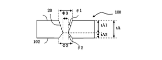
 θ1=arctan((Φ1―Φ3)/(2*tA1))  式2
 θ2=arctan((Φ2―Φ3)/(2*tA2))  式3
FIG. 4 is a schematic cross-sectional view of a glass substrate when the narrowed portion inside the through hole is not located in the central portion in the plate thickness direction. The through hole as shown in FIG. 4 can be formed, for example, by etching from the first surface 101 of the glass substrate 100 and then from the opposite second surface 102. The taper angles θ1 and θ2 at this time can be calculated from the following equations 2 and 3.
θ1 = arctan ((Φ1-Φ3) / (2 * tA1)) Equation 2
θ2 = arctan ((Φ2-Φ3) / (2 * tA2)) Equation 3
 図5は、貫通孔内部に狭窄部を有しない場合のガラス基板の模式的断面図である。図5に示すような貫通孔は、例えばエッチングをガラス基板100の第一の表面101のみから行うことで作製することができる。この時のテーパー角は、第一の表面101における孔径Φ1、第二の表面102における孔径Φ2及び板厚tAを用いて、式4から計算することができる。
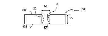
 θ=arctan((Φ1―Φ2)/(2*tA))  式4
FIG. 5 is a schematic cross-sectional view of a glass substrate when there is no constriction inside the through hole. The through hole as shown in FIG. 5 can be formed, for example, by performing etching only from the first surface 101 of the glass substrate 100. The taper angle at this time can be calculated from Equation 4 using the hole diameter Φ1 on the first surface 101, the hole diameter Φ2 on the second surface 102, and the plate thickness tA.
θ = arctan ((Φ1-Φ2) / (2 * tA)) Equation 4
 以下、本発明を実施例に基づいて説明する。なお、以下の実施例は単なる例示である。本発明は、以下の実施例に何ら限定されない。 Hereinafter, the present invention will be described based on examples. The following examples are merely examples. The present invention is not limited to the following examples.
 表1は、本発明の実施例(試料No.1~12)を表している。 Table 1 shows examples (samples Nos. 1 to 12) of the present invention.
Figure JPOXMLDOC01-appb-T000001
 
Figure JPOXMLDOC01-appb-T000001
 
 まず表中のガラス組成になるように、ガラス原料を調合したガラスバッチを白金坩堝に入れ、1600~1650℃で24時間溶融した。ガラスバッチの溶解に際しては、白金スターラーを用いて攪拌し、均質化を行った。次いで、溶融ガラスをカーボン板上に流し出し、板状に成形した後、徐冷点付近の温度で30分間徐冷した。得られた各試料について、分相性、密度、30~380℃の温度範囲における平均熱膨張係数CTE、ヤング率、歪点Ps、徐冷点Ta、軟化点Ts、高温粘度104.0dPa・sにおける温度、高温粘度103.0dPa・sにおける温度、高温粘度102.5dPa・sにおける温度、液相温度TL、初相、液相温度TLにおける粘度log10ηTL、HFエッチングレート及びβ-OH値を評価した。 First, a glass batch containing a glass raw material was placed in a platinum crucible so as to have the glass composition shown in the table, and melted at 1600 to 1650 ° C. for 24 hours. When melting the glass batch, it was stirred using a platinum stirrer to homogenize it. Next, the molten glass was poured onto a carbon plate, formed into a plate shape, and then slowly cooled at a temperature near the slow cooling point for 30 minutes. For each obtained sample, phase separation, density, average coefficient of thermal expansion CTE in the temperature range of 30 to 380 ° C., Young rate, strain point Ps, slow cooling point Ta, softening point Ts, high temperature viscosity 10 4.0 dPa. Temperature at s, high temperature viscosity 10 3.0 dPa · s temperature, high temperature viscosity 10 2.5 dPa · s temperature, liquid phase temperature TL, initial phase, liquid phase temperature TL viscosity log 10 ηTL, HF etching rate and The β-OH value was evaluated.
 分相性は、目視でガラス基板に白濁が確認されなかったものを「○」、白濁が確認されたものを「×」として、評価したものである。 The phase separation was evaluated as "○" when no white turbidity was visually confirmed on the glass substrate and "×" when white turbidity was confirmed.
 密度は、周知のアルキメデス法によって測定した値である。 Density is a value measured by the well-known Archimedes method.
 30~380℃の温度範囲における平均熱膨張係数CTEは、ディラトメーターで測定した値である。 The average coefficient of thermal expansion CTE in the temperature range of 30 to 380 ° C. is a value measured by a dilatometer.
 ヤング率は、周知の共振法で測定した値を指す。 Young's modulus refers to the value measured by the well-known resonance method.
 歪点Ps、徐冷点Ta、軟化点Tsは、ASTM C336及びC338の方法に基づいて測定した値である。 The strain point Ps, the slow cooling point Ta, and the softening point Ts are values measured based on the methods of ASTM C336 and C338.
 高温粘度104.0dPa・s、103.0dPa・s、102.5dPa・sにおける温度は、白金球引き上げ法で測定した値である。 The temperature at the high temperature viscosity of 10 4.0 dPa · s, 10 3.0 dPa · s, and 10 2.5 dPa · s is a value measured by the platinum ball pulling method.
 液相温度TLは、標準篩30メッシュ(500μm)を通過し、50メッシュ(300μm)に残るガラス粉末を白金ボートに入れて、温度勾配炉中に24時間保持した後、結晶が析出する温度である。そして、その結晶を初相として、評価した。なお、表中で「Cri」は、クリストバライトを指している。 The liquidus temperature TL is such that the glass powder that has passed through a standard sieve of 30 mesh (500 μm) and remains in 50 mesh (300 μm) is placed in a platinum boat and held in a temperature gradient furnace for 24 hours, and then crystals are precipitated. be. Then, the crystal was evaluated as the first phase. In the table, "Cri" refers to cristobalite.
 液相粘度log10ηTLは、液相温度TLにおけるガラスの粘度を白金球引き上げ法で測定した値である。 The liquid phase viscosity log 10 ηTL is a value obtained by measuring the viscosity of glass at the liquid phase temperature TL by the platinum ball pulling method.
 HFエッチングレートは、上記の方法により測定した値である。 The HF etching rate is a value measured by the above method.
 表1から明らかなように、試料No.1~12は、ガラス組成が所定範囲内に規制されているため、HFエッチングレートが3.00μm/分以下であり、高温粘度102.5dPa・sにおける温度が1700℃以下である。よって、試料No.1~12は、HFエッチングレートが低く、生産性に優れているため、マイクロLEDディスプレイ、特にタイリング方式のマイクロLEDディスプレイの基板に好適である。なお、試料No.1~9は、ガラスに分相が生じていないため、マイクロLEDディスプレイ、特にタイリング方式のマイクロLEDディスプレイの基板に好適である。 As is clear from Table 1, the sample No. In Nos. 1 to 12, since the glass composition is regulated within a predetermined range, the HF etching rate is 3.00 μm / min or less, and the temperature at a high temperature viscosity of 10 2.5 dPa · s is 1700 ° C. or less. Therefore, the sample No. 1 to 12 have a low HF etching rate and are excellent in productivity, and are therefore suitable for a substrate of a micro LED display, particularly a tiling type micro LED display. In addition, sample No. Nos. 1 to 9 are suitable for a substrate of a micro LED display, particularly a tiling type micro LED display, because no phase separation occurs in the glass.
 表2~5は、本発明の実施例(試料No.13~61)を表している。 Tables 2 to 5 show examples (Sample Nos. 13 to 61) of the present invention.
Figure JPOXMLDOC01-appb-T000002
 
Figure JPOXMLDOC01-appb-T000002
 
Figure JPOXMLDOC01-appb-T000003
 
Figure JPOXMLDOC01-appb-T000003
 
Figure JPOXMLDOC01-appb-T000004
 
Figure JPOXMLDOC01-appb-T000004
 
Figure JPOXMLDOC01-appb-T000005
 
Figure JPOXMLDOC01-appb-T000005
 
 まず表中のガラス組成になるように、ガラス原料を調合したガラスバッチを白金坩堝に入れ、1650~1680℃で24時間溶融した。ガラスバッチの溶解に際しては、白金スターラーを用いて攪拌し、均質化を行った。次いで、溶融ガラスをカーボン板上に流し出し、板状に成形した後、徐冷点付近の温度で30分間徐冷した。得られた各試料について、分相性、密度、30~380℃の温度範囲における平均熱膨張係数CTE、ヤング率、歪点Ps、徐冷点Ta、軟化点Ts、高温粘度104.0dPa・sにおける温度、高温粘度103.0dPa・sにおける温度、高温粘度102.5dPa・sにおける温度、液相温度TL、初相、液相温度TLにおける粘度log10ηTL、HFエッチングレート及びβ-OH値を前述の方法により評価した。なお、表中で「Mul」はムライトを指しており、「Ano」はアノーサイトを指している。 First, a glass batch containing a glass raw material was placed in a platinum crucible so as to have the glass composition shown in the table, and melted at 1650 to 1680 ° C. for 24 hours. When melting the glass batch, it was stirred using a platinum stirrer to homogenize it. Next, the molten glass was poured onto a carbon plate, formed into a plate shape, and then slowly cooled at a temperature near the slow cooling point for 30 minutes. For each obtained sample, phase separation, density, average coefficient of thermal expansion CTE in the temperature range of 30 to 380 ° C., Young rate, strain point Ps, slow cooling point Ta, softening point Ts, high temperature viscosity 10 4.0 dPa. Temperature at s, high temperature viscosity 10 3.0 dPa · s temperature, high temperature viscosity 10 2.5 dPa · s temperature, liquid phase temperature TL, initial phase, liquid phase temperature TL viscosity log 10 ηTL, HF etching rate and The β-OH value was evaluated by the method described above. In the table, "Mul" refers to mullite and "Ano" refers to anorthite.
 試料No.13~61は、ガラス組成が所定範囲内に規制されているため、HFエッチングレートが3.00μm/分以下であり、ガラスに分相が生じていなかった。よって、試料No.13~61は、マイクロLEDディスプレイ、特にタイリング方式のマイクロLEDディスプレイの基板に好適である。 Sample No. In Nos. 13 to 61, the glass composition was regulated within a predetermined range, so that the HF etching rate was 3.00 μm / min or less, and no phase separation occurred in the glass. Therefore, the sample No. 13 to 61 are suitable for a substrate of a micro LED display, particularly a tiling type micro LED display.
 更に、試料No.1、4~5、8~10、24~43に対して、下記方法により微細孔の作製を行い、孔のテーパー角を確認した。 Furthermore, sample No. For 1, 4 to 5, 8 to 10, 24 to 43, fine holes were prepared by the following method, and the taper angle of the holes was confirmed.
 まず35mm×20mmの矩形状である表面を有し、厚さが500μmである各ガラス基板を準備した。このガラス基板にベッセルビーム形状に成形したフェムト秒パルスレーザーをピッチ間隔が160μmとなるように照射し、ガラス基板の中央部12.8mm×9.6mmの領域に約5000個の改質部を形成した。 First, each glass substrate having a rectangular surface of 35 mm × 20 mm and a thickness of 500 μm was prepared. This glass substrate is irradiated with a femtosecond pulse laser formed into a Bessel beam shape so that the pitch interval is 160 μm, and about 5000 modified portions are formed in a region of 12.8 mm × 9.6 mm in the center of the glass substrate. bottom.
 次に、このガラス基板について、エッチングを所定の時間行った。具体的には、エッチング液を入れたPP製試験管にガラス基板を入れ、超音波をエッチング液に印加してエッチングを行い、ガラス基板に孔を形成した。この際、テフロン(登録商標)製治具を用いて、ガラス基板を試験管底部から40mm離した状態で固定した。作製された貫通孔の形状及びガラス基板の形状は図4に示すような形状となり、その形状パラメーターを透過型光学顕微鏡(ECLIPSE LV100ND:NIKON社製)を用いて前述の方法により測定した。 Next, the glass substrate was etched for a predetermined time. Specifically, a glass substrate was placed in a PP test tube containing an etching solution, and ultrasonic waves were applied to the etching solution to perform etching to form holes in the glass substrate. At this time, a glass substrate was fixed at a distance of 40 mm from the bottom of the test tube using a Teflon (registered trademark) jig. The shape of the produced through hole and the shape of the glass substrate were as shown in FIG. 4, and the shape parameters were measured by the above-mentioned method using a transmission optical microscope (ECLIPSE LV100ND: manufactured by NIKON).
 なお、エッチング液には2.5mоl/LのHF、1.0mоl/LのHCl溶液の混酸を使用し、エッチング液の温度を30℃とした。また、超音波印加中の温度上昇を防ぐため、チラーを用いて超音波装置内の水を循環させ、水温を30℃に保った。超音波振動の印加には、超音波洗浄機(VS―100III:アズワン社製)を用いた。これにより28kHzの超音波をエッチング液に印加した。 A mixed acid of 2.5 mL / L HF and 1.0 mol / L HCl solution was used as the etching solution, and the temperature of the etching solution was set to 30 ° C. Further, in order to prevent the temperature from rising during the application of ultrasonic waves, the water in the ultrasonic device was circulated using a chiller to keep the water temperature at 30 ° C. An ultrasonic cleaner (VS-100III: manufactured by AS ONE) was used to apply the ultrasonic vibration. As a result, 28 kHz ultrasonic waves were applied to the etching solution.
 準備したガラス基板の板厚、エッチング後のガラス基板の形状及びエッチングにより作製された孔の形状を表6~14に示す。なお、表中の「HFエッチングレート」は、表1~5に記載の値であり、2.5mоl/LのHF溶液について測定されたものである。一方、孔を形成する際のエッチングではエッチング液である2.5mоl/LのHF、1.0mоl/LのHCl溶液の混酸を使用し、また超音波を印加しているため、孔を形成した際のエッチングレートは表中の「HFエッチングレート」とは異なる値となる。 Tables 6 to 14 show the thickness of the prepared glass substrate, the shape of the glass substrate after etching, and the shape of the holes produced by etching. The "HF etching rate" in the table is the value shown in Tables 1 to 5, and was measured for a 2.5 mol / L HF solution. On the other hand, in the etching when forming the pores, a mixed acid of 2.5 mol / L HF and 1.0 mol / L HCl solution, which are etching solutions, was used, and ultrasonic waves were applied, so that the pores were formed. The etching rate at this time is different from the "HF etching rate" in the table.
Figure JPOXMLDOC01-appb-T000006
 
Figure JPOXMLDOC01-appb-T000006
 
Figure JPOXMLDOC01-appb-T000007
 
Figure JPOXMLDOC01-appb-T000007
 
Figure JPOXMLDOC01-appb-T000008
 
Figure JPOXMLDOC01-appb-T000008
 
Figure JPOXMLDOC01-appb-T000009
 
Figure JPOXMLDOC01-appb-T000009
 
Figure JPOXMLDOC01-appb-T000010
 
Figure JPOXMLDOC01-appb-T000010
 
Figure JPOXMLDOC01-appb-T000011
 
Figure JPOXMLDOC01-appb-T000011
 
Figure JPOXMLDOC01-appb-T000012
 
Figure JPOXMLDOC01-appb-T000012
 
Figure JPOXMLDOC01-appb-T000013
 
Figure JPOXMLDOC01-appb-T000013
 
Figure JPOXMLDOC01-appb-T000014
 
Figure JPOXMLDOC01-appb-T000014
 
 これらの結果から、HFエッチングレートが小さい程、微細孔を作製した際のテーパー角が小さくなることが分かる。また、HFエッチングレートが小さい程、孔深さを増加させるためにエッチング時間を増加させても、テーパー角が大きくなり難いことが分かる。 From these results, it can be seen that the smaller the HF etching rate, the smaller the taper angle when micropores are formed. Further, it can be seen that the smaller the HF etching rate, the more difficult it is for the taper angle to increase even if the etching time is increased in order to increase the hole depth.
 100 ガラス基板
 101 第一の表面
 100 第二の表面
 120 改質部
 20 貫通孔
 21 非貫通孔
100 Glass substrate 101 First surface 100 Second surface 120 Modified part 20 Through hole 21 Non-through hole

Claims (8)

  1.  ガラス組成として、モル%で、SiO 65.0~80.0%、Al 2.0~15.0%、B 0~15.0%、LiO+NaO+KO 0.001~0.1%未満、MgO 0~15.0%、CaO 0~15.0%、SrO 0~15.0%、BaO 0~15.0%、SnO 0~1.0%、As 0~0.050%未満、Sb 0~0.050%未満を含有する、ガラス基板。 As the glass composition, in mol%, SiO 2 65.0 to 80.0%, Al 2 O 3 2.0 to 15.0%, B 2 O 30 to 15.0%, Li 2 O + Na 2 O + K 2 O 0.001 to less than 0.1%, MgO 0 to 15.0%, CaO 0 to 15.0%, SrO 0 to 15.0%, BaO 0 to 15.0%, SnO 20 to 1.0% , As 2 O 30 to less than 0.050%, Sb 2 O 30 to less than 0.050%, a glass substrate.
  2.  ガラス組成として、モル%で、SiO 69.6~80.0%、Al 7.1~13.0%、B 2.0~7.5%、LiO+NaO+KO 0.001~0.1%未満、MgO 3.4~10.0%、CaO 0.1~5.5%、SrO 0.1~15.0%、BaO 0.3~3.0%、SnO 0.01~1.0%、As 0~0.050%未満、Sb 0~0.050%未満を含有する、請求項1に記載のガラス基板。 As the glass composition, in mol%, SiO 2 69.6 to 80.0%, Al 2 O 3 7.1 to 13.0%, B 2 O 3 2.0 to 7.5%, Li 2 O + Na 2 O + K. 2O 0.001 to less than 0.1%, MgO 3.4 to 10.0%, CaO 0.1 to 5.5%, SrO 0.1 to 15.0%, BaO 0.3 to 3.0 The glass substrate according to claim 1, which contains%, SnO 2 0.01 to 1.0%, As 2 O 30 to less than 0.050%, and Sb 2 O 30 to less than 0.050%.
  3.  ガラス組成として、モル%で、SiO 69.6~80.0%、Al 7.1~12.5%、B 2.7~7.5%、LiO+NaO+KO 0.001~0.1%未満、MgO 3.4~10.0%、CaO 0.1~5.5%、SrO 0.5~3.8%、BaO 0.3~3.0%、SnO 0.01~1.0%、As 0~0.050%未満、Sb 0~0.050%未満を含有する、請求項1又は2に記載のガラス基板。 As the glass composition, in mol%, SiO 2 69.6 to 80.0%, Al 2 O 3 7.1 to 12.5%, B 2 O 3 2.7 to 7.5%, Li 2 O + Na 2 O + K. 2O 0.001 to less than 0.1%, MgO 3.4 to 10.0%, CaO 0.1 to 5.5%, SrO 0.5 to 3.8%, BaO 0.3 to 3.0 The glass substrate according to claim 1 or 2, which contains%, SnO 2 0.01 to 1.0%, As 2 O 30 to less than 0.050%, and Sb 2 O 30 to less than 0.050%. ..
  4.  ガラス組成として、モル%で、SiO 69.7~80.0%、Al 2.0~15.0%、B 2.5~15.0%、LiO+NaO+KO 0.001~0.1%未満、MgO 0~15.0%、CaO 0~8.2%、SrO 0~15.0%、BaO 1.1~15.0%、SnO 0.01~1.0%、TiO 0.0005~0.1%、As 0~0.050%未満、Sb 0~0.050%未満を含有する、請求項1~3の何れかに記載のガラス基板。 As the glass composition, in mol%, SiO 2 69.7 to 80.0%, Al 2 O 3 2.0 to 15.0%, B 2 O 3 2.5 to 15.0%, Li 2 O + Na 2 O + K. 2O 0.001 to less than 0.1%, MgO 0 to 15.0%, CaO 0 to 8.2%, SrO 0 to 15.0%, BaO 1.1 to 15.0%, SnO 20 . Claims 1 to 3 containing 01 to 1.0%, TiO 2 0.0005 to 0.1%, As 2 O 30 to less than 0.050%, and Sb 2 O 30 to less than 0.050%. The glass substrate described in any of.
  5.  HFエッチングレートが3.00μm/分以下である、請求項1~4の何れかに記載のガラス基板。 The glass substrate according to any one of claims 1 to 4, wherein the HF etching rate is 3.00 μm / min or less.
  6.  高温粘度102.5dPa・sにおける温度が1760℃以下である、請求項1~5の何れかに記載のガラス基板。 The glass substrate according to any one of claims 1 to 5, wherein the temperature at a high temperature viscosity of 10 2.5 dPa · s is 1760 ° C. or lower.
  7.  貫通孔を有する、請求項1~6の何れかに記載のガラス基板。 The glass substrate according to any one of claims 1 to 6, which has a through hole.
  8.  マイクロLEDディスプレイに用いる、請求項1~7の何れかに記載のガラス基板。 The glass substrate according to any one of claims 1 to 7, which is used for a micro LED display.
PCT/JP2021/041107 2020-11-16 2021-11-09 Glass substrate WO2022102598A1 (en)

Priority Applications (4)

Application Number Priority Date Filing Date Title
JP2022561926A JPWO2022102598A1 (en) 2020-11-16 2021-11-09
KR1020237018190A KR20230098828A (en) 2020-11-16 2021-11-09 glass substrate
US18/033,475 US20230399253A1 (en) 2020-11-16 2021-11-09 Glass substrate
CN202180071873.XA CN116490476A (en) 2020-11-16 2021-11-09 Glass substrate

Applications Claiming Priority (2)

Application Number Priority Date Filing Date Title
JP2020190229 2020-11-16
JP2020-190229 2020-11-16

Publications (1)

Publication Number Publication Date
WO2022102598A1 true WO2022102598A1 (en) 2022-05-19

Family

ID=81601315

Family Applications (1)

Application Number Title Priority Date Filing Date
PCT/JP2021/041107 WO2022102598A1 (en) 2020-11-16 2021-11-09 Glass substrate

Country Status (6)

Country Link
US (1) US20230399253A1 (en)
JP (1) JPWO2022102598A1 (en)
KR (1) KR20230098828A (en)
CN (1) CN116490476A (en)
TW (1) TW202229192A (en)
WO (1) WO2022102598A1 (en)

Citations (8)

* Cited by examiner, † Cited by third party
Publication number Priority date Publication date Assignee Title
JP2000044278A (en) * 1998-05-20 2000-02-15 Nippon Electric Glass Co Ltd Glass substrate for display
WO2017038075A1 (en) * 2015-08-31 2017-03-09 日本板硝子株式会社 Method for producing glass with fine structure
JP2017533171A (en) * 2014-10-31 2017-11-09 コーニング インコーポレイテッド Dimensionally stable, rapidly etched glass
WO2018025883A1 (en) * 2016-08-05 2018-02-08 旭硝子株式会社 Glass substrate, semiconductor device, and display device
JP2019066613A (en) * 2017-09-29 2019-04-25 大日本印刷株式会社 Display panel and tiling display unit
WO2019084077A1 (en) * 2017-10-27 2019-05-02 Corning Incorporated Through glass via fabrication using a protective material
WO2020149040A1 (en) * 2019-01-17 2020-07-23 日本板硝子株式会社 Microstructured glass substrate and method for manufacturing microstructured glass substrate
WO2020184175A1 (en) * 2019-03-08 2020-09-17 日本電気硝子株式会社 Glass sheet

Family Cites Families (2)

* Cited by examiner, † Cited by third party
Publication number Priority date Publication date Assignee Title
JPS6333282U (en) 1986-08-20 1988-03-03
JP2018205525A (en) 2017-06-05 2018-12-27 ソニー株式会社 Display device and electronic equipment

Patent Citations (8)

* Cited by examiner, † Cited by third party
Publication number Priority date Publication date Assignee Title
JP2000044278A (en) * 1998-05-20 2000-02-15 Nippon Electric Glass Co Ltd Glass substrate for display
JP2017533171A (en) * 2014-10-31 2017-11-09 コーニング インコーポレイテッド Dimensionally stable, rapidly etched glass
WO2017038075A1 (en) * 2015-08-31 2017-03-09 日本板硝子株式会社 Method for producing glass with fine structure
WO2018025883A1 (en) * 2016-08-05 2018-02-08 旭硝子株式会社 Glass substrate, semiconductor device, and display device
JP2019066613A (en) * 2017-09-29 2019-04-25 大日本印刷株式会社 Display panel and tiling display unit
WO2019084077A1 (en) * 2017-10-27 2019-05-02 Corning Incorporated Through glass via fabrication using a protective material
WO2020149040A1 (en) * 2019-01-17 2020-07-23 日本板硝子株式会社 Microstructured glass substrate and method for manufacturing microstructured glass substrate
WO2020184175A1 (en) * 2019-03-08 2020-09-17 日本電気硝子株式会社 Glass sheet

Also Published As

Publication number Publication date
KR20230098828A (en) 2023-07-04
TW202229192A (en) 2022-08-01
JPWO2022102598A1 (en) 2022-05-19
US20230399253A1 (en) 2023-12-14
CN116490476A (en) 2023-07-25

Similar Documents

Publication Publication Date Title
JP5269870B2 (en) Glass plate and method for producing glass plate
JP5819392B2 (en) Cover glass manufacturing method and cover glass
JP5867953B2 (en) Tempered glass and tempered glass
TW201702201A (en) Glass for laser processing, and method for producing glass with hole using said glass for laser processing
TW201702199A (en) Glass for laser processing, and method for producing glass with hole using said glass for laser processing
KR20160030067A (en) Glass
JP2002308643A (en) Alkali-free glass and glass substrate for display
KR102291291B1 (en) Method for manufacturing alkali-free glass
JP2022009846A (en) Alkali-free glass
WO2022196510A1 (en) Glass substrate, glass base-plate for through-hole formation, and glass substrate manufacturing method
JPWO2018123675A1 (en) Glass
WO2018116953A1 (en) Glass
KR102479156B1 (en) Alkali-free glass and its manufacturing method
WO2022102598A1 (en) Glass substrate
JP2006347796A (en) Glass member, product using the same, and method for production of the product
WO2022075068A1 (en) Glass substrate having through hole
CN111164056A (en) Glass

Legal Events

Date Code Title Description
121 Ep: the epo has been informed by wipo that ep was designated in this application

Ref document number: 21891844

Country of ref document: EP

Kind code of ref document: A1

ENP Entry into the national phase

Ref document number: 2022561926

Country of ref document: JP

Kind code of ref document: A

WWE Wipo information: entry into national phase

Ref document number: 202180071873.X

Country of ref document: CN

ENP Entry into the national phase

Ref document number: 20237018190

Country of ref document: KR

Kind code of ref document: A

NENP Non-entry into the national phase

Ref country code: DE

122 Ep: pct application non-entry in european phase

Ref document number: 21891844

Country of ref document: EP

Kind code of ref document: A1