WO2022102207A1 - ロボット制御システム、ロボット制御方法及びプログラム - Google Patents
ロボット制御システム、ロボット制御方法及びプログラム Download PDFInfo
- Publication number
- WO2022102207A1 WO2022102207A1 PCT/JP2021/031322 JP2021031322W WO2022102207A1 WO 2022102207 A1 WO2022102207 A1 WO 2022102207A1 JP 2021031322 W JP2021031322 W JP 2021031322W WO 2022102207 A1 WO2022102207 A1 WO 2022102207A1
- Authority
- WO
- WIPO (PCT)
- Prior art keywords
- robot
- robot device
- environment sensor
- learning
- output
- Prior art date
- Legal status (The legal status is an assumption and is not a legal conclusion. Google has not performed a legal analysis and makes no representation as to the accuracy of the status listed.)
- Ceased
Links
Images

Classifications
-
- B—PERFORMING OPERATIONS; TRANSPORTING
- B25—HAND TOOLS; PORTABLE POWER-DRIVEN TOOLS; MANIPULATORS
- B25J—MANIPULATORS; CHAMBERS PROVIDED WITH MANIPULATION DEVICES
- B25J9/00—Programme-controlled manipulators
- B25J9/16—Programme controls
- B25J9/1694—Programme controls characterised by use of sensors other than normal servo-feedback from position, speed or acceleration sensors, perception control, multi-sensor controlled systems, sensor fusion
- B25J9/1697—Vision controlled systems
-
- B—PERFORMING OPERATIONS; TRANSPORTING
- B25—HAND TOOLS; PORTABLE POWER-DRIVEN TOOLS; MANIPULATORS
- B25J—MANIPULATORS; CHAMBERS PROVIDED WITH MANIPULATION DEVICES
- B25J13/00—Controls for manipulators
-
- B—PERFORMING OPERATIONS; TRANSPORTING
- B25—HAND TOOLS; PORTABLE POWER-DRIVEN TOOLS; MANIPULATORS
- B25J—MANIPULATORS; CHAMBERS PROVIDED WITH MANIPULATION DEVICES
- B25J9/00—Programme-controlled manipulators
- B25J9/16—Programme controls
- B25J9/1628—Programme controls characterised by the control loop
- B25J9/163—Programme controls characterised by the control loop learning, adaptive, model based, rule based expert control
-
- B—PERFORMING OPERATIONS; TRANSPORTING
- B25—HAND TOOLS; PORTABLE POWER-DRIVEN TOOLS; MANIPULATORS
- B25J—MANIPULATORS; CHAMBERS PROVIDED WITH MANIPULATION DEVICES
- B25J9/00—Programme-controlled manipulators
- B25J9/16—Programme controls
- B25J9/1656—Programme controls characterised by programming, planning systems for manipulators
- B25J9/1664—Programme controls characterised by programming, planning systems for manipulators characterised by motion, path, trajectory planning
-
- G—PHYSICS
- G05—CONTROLLING; REGULATING
- G05B—CONTROL OR REGULATING SYSTEMS IN GENERAL; FUNCTIONAL ELEMENTS OF SUCH SYSTEMS; MONITORING OR TESTING ARRANGEMENTS FOR SUCH SYSTEMS OR ELEMENTS
- G05B2219/00—Program-control systems
- G05B2219/30—Nc systems
- G05B2219/37—Measurements
- G05B2219/37555—Camera detects orientation, position workpiece, points of workpiece
-
- G—PHYSICS
- G05—CONTROLLING; REGULATING
- G05B—CONTROL OR REGULATING SYSTEMS IN GENERAL; FUNCTIONAL ELEMENTS OF SUCH SYSTEMS; MONITORING OR TESTING ARRANGEMENTS FOR SUCH SYSTEMS OR ELEMENTS
- G05B2219/00—Program-control systems
- G05B2219/30—Nc systems
- G05B2219/40—Robotics, robotics mapping to robotics vision
- G05B2219/40053—Pick 3-D object from pile of objects
Definitions
- the present invention relates to a robot control system, a robot control method and a program.
- a robot device represented by an industrial robot repeatedly performs an operation only for a stored position of a work object. Therefore, in order for the robot device to execute a work, programming for designating a position according to the work content is required. is necessary. However, the robot device may not be able to respond to the displacement of the work object or the change of the work content. Therefore, there is known a technique of controlling a robot device to perform a predetermined work by using a machine learning technique including a neural network.
- a learner (learned model) that has been machine-learned to generate an operation command of a robot device from information of an environment sensor such as a camera in a plurality of work situations where the positions of work objects are different is used. Then, by controlling the robot device by inputting the output of the environment sensor to the machine-learned learner and using the operation command generated, the robot device can execute the work even in different work situations.
- Patent Document 1 discloses a system in which a system is made to perform a predetermined task by using a learning module including a trained model or a model equivalent thereto.
- a predictor composed of a trained model outputs a gripping success rate and a constraint satisfaction degree based on a plurality of motion candidates, an image taken by a camera, and a posture of a robot, and operates.
- the evaluation value is calculated based on the gripping success rate and the constraint satisfaction degree, and the next operation is determined from the operation candidates based on the evaluation value.
- the gripping success rate is the probability of success when each motion candidate is performed.
- the constraint satisfaction degree indicates whether or not the constraint condition specified by the user is satisfied.
- the movement of the robot can be determined based on the image taken by the camera, and the movement can be adjusted according to the input of constraints such as the user, so that the robot can work in some work situations. Can be executed.
- the machine-learned learner (learned model) is basically an approximate inferencer based on statistics, and if the learner is input in a situation close to the machine-learned situation, it can be inferred accurately, but learning. If the input is made in a situation different from that when the device is machine-learned, the inference accuracy of the learner will decrease.
- the robot device cannot be operated properly under environmental conditions that affect the image taken by the camera, such as the brightness around the work object being different from the brightness at the time of learning by the learning device. There is.
- the operation according to the input of the constraint condition of the user it is necessary for the user to correctly recognize the change in the environment and correctly convert the recognized content into the constraint condition.
- the user may not be able to specify constraints with high accuracy, and the robot device may not operate properly.
- the present invention has been made in view of the above situation, and when it is detected that the current environmental conditions of the robot device using the learning device are different from the environmental conditions at the time when the learning device is machine-learned.
- the purpose is to enable the robot device to perform the work properly.
- the robot control system of one aspect of the present invention issues an operation command of the robot device, an environment sensor for acquiring the environmental conditions of the robot device, and a robot device corresponding to the output of the environment sensor.
- the current output of the environment sensor is input to the trained model that has undergone machine learning to generate, and the operation command of the robot device corresponding to the current output of the environment sensor output from the trained model is generated to generate the robot.
- the robot device when it is detected that the current environmental conditions of the robot device using the learner are different from the environmental conditions at the time when the learner is machine-learned, the current environmental conditions. And / or adjust the setting of the environment sensor based on the degree of agreement with the environmental conditions at the time of learning. Therefore, the robot device can appropriately perform the work according to the operation command of the robot device with such adjustment and / or the setting of the environment sensor. Issues, configurations and effects other than those described above will be clarified by the following description of the embodiments.
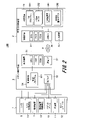
- FIG. 1 is a schematic diagram showing an example of the overall configuration of the robot control system according to the first embodiment.
- the robot control device 5 connected to each part of the robot device 1 is communicably connected to the learning type control device 2 via a network 3 such as the Internet or a LAN.
- the robot device 1 is a control target of the robot control system 100, and the robot control system 100 may be configured not to include the robot device 1.
- the robot device 1 executes the work instructed for the work object 4.
- the robot device 1 includes a work robot 6 (robot body), a lighting device 7, a lighting device moving mechanism 13 that changes the position of the lighting device 7, a camera 8, and a camera moving mechanism 14 that changes the positions of the camera 8. And have. These elements constituting the robot device 1 are housed in the transparent cover body 16.
- the cover body 16 is not essential.
- the lighting device 7, the lighting device moving mechanism 13, the camera 8, and the camera moving mechanism 14 are peripheral devices of the working robot 6.
- the camera 8 has a function of obtaining an image signal of an optical image including a work object 4 handled by the robot device 1.
- the camera 8 is also an environment sensor that measures the working environment (environmental conditions) of the robot device 1.
- the working robot 6 and the peripheral device are not distinguished, or when they are generically referred to, the term "robot device" is used.
- the working robot 6 is composed of a robot arm 10 and an end effector 12 attached to the tip of the robot arm 10.
- the robot arm 10 has a plurality of joints and can be freely operated by being driven by an actuator such as a motor (not shown) provided in each joint.
- An angle meter 11 is attached to each joint of the robot arm 10.
- the working robot 6 is configured so that the position of the end effector 12 can be calculated by calculating the posture of the robot arm 10.
- an example of a vertical articulated robot is shown, but it may be a Cartesian coordinate robot, a horizontal articulated robot, a parallel link robot, or the like.
- the working robot 6, the lighting device 7, the lighting device moving mechanism 13, the camera 8, and the camera moving mechanism 14 of the robot device 1 are connected to the robot control device 5.
- the working robot 6 and each peripheral device operate in response to a control command (motor current of the working robot 6, applied voltage of the lighting device 7, control signal of the camera 8, etc.) from the robot control device 5, and the robot device.
- Information indicating the state of 1 is transmitted to the robot control device 5.
- the information indicating the state of the robot device 1 is, for example, the joint angle of the working robot 6, the brightness of the illumination light of the illumination device 7, the position of the illumination device 7 by the illumination device moving mechanism 13, and the image taken by the camera 8 (camera). Image), and the position of the camera 8 by the camera moving mechanism 14.
- the brightness of the illumination light of the illumination device 7 is expressed by using, for example, a luminous flux (lumens). By changing the luminous flux of the illumination light of the lighting device 7, the illuminance inside the robot device 1 or around the robot device 1 changes, and the change appears in the brightness and saturation of the camera image.
- the joint angle of the working robot 6 is an angle formed by elements (base, arm, hand, etc.) connected by joints.
- the information representing the state of the robot device 1 may be abbreviated as "the state of the robot device 1".
- the robot control device 5 is connected to the learning type control device 2 via the network 3.
- the robot control device 5 transmits information representing the state of the robot device 1 obtained from the robot device 1 to the learning type control device 2 via the network 3.
- the robot control device 5 includes an operation command output by the learning type control device 2 (target joint angle of the working robot 6, target light beam of the lighting device 7, etc.) and the state of the robot device 1 input from the robot device 1.
- the control command for the robot device 1 is calculated based on the above.
- the learning type control device 2 outputs the target joint angle of each joint of the working robot 6 to the robot control device 5 as an operation command so that the end effector 12 moves to a desired position.
- the robot control device 5 makes the angle of each joint match the target joint angle with respect to the target joint angle received from the learning type control device 2 based on the angle information of the angle meter 11 received from the working robot 6.
- the motor current of the working robot 6 is output as a control command.
- the operation command output by the learning type control device 2 is not limited to the target angle of each joint, and is, for example, the X, Y, Z positions of the end effector 12 and the positions represented by the yaw, pitch, and roll angles. / It may be posture information.
- the robot control device 5 may be configured to internally calculate the solution of the inverse kinematics of the working robot 6 and output the motor current of the working robot 6 as a control command.
- FIG. 2 is a schematic diagram showing an example of a hardware configuration for executing software of the robot control system 100.
- the interface is described as "I / F”.
- the robot control device 5 is a computer in which the control device 51, the communication interface 52, the control interface 53, and the storage device 54 are electrically connected to each other via a system bus.
- the control device 51 includes a CPU (Central Processing Unit), a RAM (Random Access Memory), a ROM (Read Only Memory), and the like, and performs information processing based on a program and various data that realize the functions according to the present embodiment. Configured to run.
- another processing device such as an MPU (Micro Processing Unit) may be used.
- the communication interface 52 is an interface for connecting to the learning type control device 2 and transmitting / receiving operation commands to the robot device 1 and data related to the state of the robot device 1.
- the communication interface 52 communicates with the communication interface 22 of the learning type control device 2 via the network 3.
- the control interface 53 is an interface for connecting to the robot device 1 to send and receive a control command to the robot device 1 and data related to the state of the robot device 1, and is appropriately configured according to the devices constituting the robot device 1. To. Since the configuration of the robot device 1 connected to the control interface 53 has already been described with reference to FIG. 1, the description thereof is omitted here.
- the storage device 54 is an auxiliary storage device such as a hard disk drive or a semiconductor memory, and stores a control program 521 or the like executed by the control device 51.
- the ROM and the storage device 54 permanently record programs, data, and the like necessary for the CPU of the control device 51 to operate, and are non-transient computer-readable stores that store the programs executed by the CPU. It is used as an example of a recording medium.
- the control program 521 stored in the storage device 54 is expanded and executed in the RAM of the control device 51.
- the control program 521 is based on the operation command generated by the learning type control device 2 input from the communication interface 52 and / or the setting of the camera 8 and the information indicating the state of the robot device 1 input from the control interface 53. Then, a control command for the robot device 1 is generated. Then, the control program 521 outputs a control command from the control interface 53 to the robot device 1. Further, the control program 521 outputs the information indicating the state of the robot device 1 input from the control interface 53 from the communication interface 52 to the learning type control device 2.
- the learning type control device 2 is a computer in which the control device 21, the communication interface 22, the input device 23, and the storage device 24 are electrically connected to each other via a system bus.
- the control device 21 includes a CPU, RAM, ROM, and the like, and is configured to execute information processing based on a program and various data that realize the functions according to the present embodiment.
- the communication interface 22 is an interface for connecting to the robot control device 5 to send and receive an operation command of the robot device 1 to the robot control device 5 and a state of the robot device 1.
- the communication interface 22 communicates with the communication interface 52 of the robot control device 5 via the network 3.
- the input device 23 is a device that captures input from a user such as a mouse or keyboard, and controls execution of a program of the learning type control device 2.
- the storage device 24 is an auxiliary storage device such as a hard disk drive or a semiconductor memory, and stores a learning program 251 executed by the control device 21, a learning device calculation program 261, learning data 252, learning device weight data 262, and the like.
- the ROM and the storage device 24 permanently record programs, data, and the like necessary for the CPU of the control device 21 to operate, and are non-transient computer-readable stores that store the programs executed by the CPU. It is used as an example of a recording medium.
- the learning type control device 2 is started by turning on the power or the like, the learning program 251 and the learning device calculation program 261 stored in the storage device 24 are expanded in the RAM of the control device 21.
- the learning program 251 When the user instructs the user to execute learning via the input device 23, the learning program 251 generates learning data 252 using information such as the state and environment of the robot device 1 input from the communication interface 22. And record in the storage device 24. Then, the learning program 251 uses the learning data 252 to cause a learning device 256 (see FIG. 4) described later to perform machine learning, and generates learning device weight data 262 as learned parameters.
- the learner 256 is a so-called supervised learning model.
- the learner weight data 262 is a neural network weight.
- the learner calculation program 261 reads the learner weight data 262 when the user instructs the user to execute the control of the robot device 1 via the input device 23. Then, the learner calculation program 261 uses the state of the robot device 1 obtained from the communication interface 22 and the learned learner 264 (see FIG. 7) described later to give an operation command of the robot device 1 and set the camera 8. Is calculated.
- the learner 264 is a trained model (inference program) that reflects the result of learning (learned parameters) by the learner 256.
- the learner calculation program 261 outputs the generated operation command of the robot device 1 and the setting of the camera 8 from the communication interface 22 to the robot control device 5.
- the robot control device 5 outputs a control command to the robot device 1 and controls the operation based on the operation command of the robot device 1 and / or the setting of the camera 8 input from the learning type control device 2.
- the robot control device 5 and the learning type control device 2 are not limited to the configuration in which they are connected via the network 3.
- the robot control device 5 and the learning type control device 2 may have a configuration in which the communication interface 52 and the communication interface 22 are directly connected by a dedicated line or the like. Further, the control interface 53 and the communication interface 52 may be the same, and the robot control device 5 may be configured to output a control command to the robot device 1 via the network 3.
- the learning program 251 and the learning device calculation program 261 may not be stored in the same learning type control device 2, and may be stored in different learning type control devices.
- the learning data 252 and the learning device weight data 262 may be configured to be communicated between different learning type control devices via the network 3.
- the learning type control device 2 and the robot control device 5 may be configured with the same hardware. That is, the control program 521, the learning program 251 and the learner arithmetic program 261 may be configured to be executed on the same hardware.
- the robot device 1 is based on a comparison between the environmental conditions when the learning type control device 2 learns the operation command of the robot device 1 and the current output (environmental conditions) of the environment sensor.
- a method of adjusting the operation command of FIG. 3 to FIG. 8 will be described with reference to FIGS. 3 to 8.
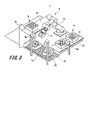
- FIG. 3 is an external view showing an example of the work executed by the robot device 1. A working example of the robot device 1 will be described with reference to FIG.
- the working robot 6 is particularly useful for a process of repeatedly executing a predetermined work.
- FIG. 3 shows a process in which the working robot 6 repeats the work of transferring the work object 4 bulked in the carry-in tray 32 to the carry-out tray 35.
- the work robot 6 grabs the work objects 4 bulked in bulk in the carry-in tray 32 carried in from the carry-in line 31 one by one by the end effector 12, and arranges them in the carry-out tray 35 carried in from the carry-out tray line 33. Deploy. Then, the working robot 6 grips the carry-out tray 35 on which the work object 4 is arranged and moves to the carry-out line 34. The working robot 6 repeatedly executes these tasks.
- the work object 4 that can be gripped is selected from a plurality of work objects 4 in which the work robot 6 is randomly arranged. It is necessary to control the working robot 6 so that only one is selected and only the selected work object 4 is gripped. It is difficult to deal with such an operation only by designating a predetermined position of the end effector 12. Therefore, the operation of gripping the work objects 4 stacked separately is machine-learned in a plurality of work scenes in which the positions and orientations (attitudes) of the work objects 4 are changed, and the machine-learned learning type control device 2 is generated. The working robot 6 is controlled by using the operation command of the working robot 6. As a result, even if the arrangement (position, posture) of the work object 4 is random, it is expected that the work robot 6 can surely grip the work object 4 with the end effector 12.
- the carry-out tray 35 of the carry-out tray line 33 may be carried in with the position or orientation of the carry-out tray 35 deviated. Therefore, when arranging the work object 4 on the carry-out tray 35, it is necessary to arrange the work object 4 according to the position and orientation of the carry-out tray 35. It is difficult to deal with such an operation only by designating a predetermined position of the end effector 12. Therefore, in the robot control system 100, the operation of arranging the work object 4 on the carry-out tray 35 is machine-learned in a plurality of work scenes in which the positions and orientations of the carry-out tray 35 are changed, and the work inferred by the machine-learned learner. The working robot 6 is controlled by using the operation command of the working robot 6. As a result, it can be expected that the work object 4 can be appropriately arranged and arranged on the carry-out tray 35 even when the carry-out tray 35 is carried in with the position or orientation deviated from each other.
- the positions and orientations of the camera 8a for grasping the state of the work objects 4 bulked in the carry-in tray 32 and the carry-out tray 35 are determined.
- a camera 8b for grasping may be installed.
- lighting devices 7a and 7b for adjusting the brightness of the acquired images of the cameras 8a and 8b may be installed.
- the states of the acquired images (for example, brightness, saturation, etc.) of the cameras 8a, 8b at a certain point in time are machine-learned by the learner. It may not be the same as the state of the acquired image.
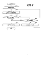
- FIG. 4 is a schematic diagram showing an example of the software configuration of the learning program 251 executed by the learning type control device 2 in the robot control system 100.
- FIG. 5 is a flowchart showing an example of a procedure in which the learning program 251 collects the learning data 252.
- FIG. 6 is a flowchart showing an example of a procedure in which the learning program 251 causes the learner 256 to perform machine learning.
- All the processing steps in FIG. 5 are executed at predetermined sampling timings in the learning type control device 2. Further, in the RAM of the control device 21, the number of times the learner 256 is updated in step S15 (see FIG. 6) described later is stored, and the number of updates is called from the RAM when the number of updates is determined in step S14. Further, the learning program 251 is configured to include a data collecting unit 253 and a learning processing unit 255 as software modules when they are expanded in the RAM of the control device 21 and executed by the CPU.
- the data collecting unit 253 of the learning program 251 collects learning data 252 of a plurality of work situations for making the learning device 256 perform machine learning will be described.
- the data collection unit 253 includes a collection period determination unit 254 that determines the collection period of the learning data 252 based on the user's instruction via the input device 23. The user instructs the input device 23 to start and end the acquisition of the learning data 252.
- the data collection unit 253 sets the communication interface 22 to the camera image of the camera 8 in the collection period determined by the collection period determination unit 254, the joint angle of the work robot 6, and the target joint angle which is an operation command of the work robot 6. It is acquired through the device and stored in the storage device 24 as learning data 252 in one work scene.
- a plurality of joint angles of the working robot 6 are specified in advance in the control program 521 of the robot control device 5, and the joint angles are programmed so as to be the specified joint angles at a predetermined time. Then, the data collection unit 253 acquires the data for each sampling timing when the work is being executed by the control program 521 from the robot device 1, and stores the time-series data as one learning data 252 in the storage device 24. do. The data collection unit 253 collects learning data 252 in the number of work situations specified by the input device 23.
- the work robot 6 learns the work of grasping the work object 4 piled up in bulk on the carry-in tray 32 many times, so that a plurality of learning data 252 having different positions and postures of the work object 4 can be learned. Can be collected.
- the collection period determination unit 254 of the data collection unit 253 determines whether or not a data collection instruction has been input from the user via the input device 23 (S1). Then, if there is a data collection instruction (YES in S1), the collection period determination unit 254 proceeds to step S2, and if there is no data collection instruction (NO in S1), the collection period determination unit performs the determination process in step S1. Execute again to monitor the input of data collection instructions.
- step S1 when the data collection unit 253 determines that the data collection instruction has been input (YES in S1), the data collection unit 253 issues one sampling of camera image, the joint angle of the work robot 6, and the operation command of the work robot 6. It is recorded in the learning data 252 in the work scene (S2), and the process proceeds to step S3.
- the data collection unit 253 determines whether or not the data of the collection period specified by the user has been recorded via the input device 23 (S3). Then, if the data for the designated collection period has not been recorded (NO in S3), the data collection unit 253 returns the process to step S2 and continues recording the data. On the other hand, when the data of the designated collection period is recorded (YES in S3), the data collection unit 253 proceeds to the process in step S4, assuming that the learning data 252 in one work scene has been acquired.
- the data collection unit 253 determines whether or not the learning data 252 in the number or more of the work scenes instructed via the input device 23 has been collected (S4). Then, if the collection of the learning data 252 in the instructed number or more of the work scenes is not completed (NO in S4), the data collection unit 253 returns the process to before step S1 and learns in different work scenes. The process is continued so as to collect the data 252. On the other hand, when the collection of the learning data 252 in the designated number of work scenes is completed (YES in S4), the data collection unit 253 ends a series of processes.
- the determination of the start of data collection in step S1 and the determination of the end of the collection period in step S3 may be different methods.
- the data recording may be started from the moment when the end effector 12 of the working robot 6 reaches a predetermined position, and the data may be recorded up to the time point specified by the user via the input device 23. ..
- the content of the learning data 252 to be collected may be different from the camera image, the joint angle of the working robot 6, and the operation command of the working robot 6, and the camera image and the operation command of the working robot 6 may be different. It may be composed of only.
- the operation command of the robot device 1 is not limited to the target joint angle of the working robot 6, but is the X, Y, Z positions of the end effector 12 and the position information and the posture information represented by the yaw, pitch, and roll angle. You may.
- the learning processing unit 255 includes a learning device 256 and a weight update amount calculation unit 257.
- the learning device 256 inputs the camera image of the learning data 252 and the robot joint angle
- the learning device 256 reproduces the camera image at the time of learning (performs processing such as noise removal) and uses the estimated joint image of the working robot 6 as the target joint angle. Outputs a certain estimated operation command.
- the estimated image is an example of a reproduction signal generated based on the output of the environment sensor.
- a neural network composed of a plurality of layers can be applied to the learner 256. Weights and biases are set for each neuron that constitutes a neural network. One layer is formed by a plurality of neurons, and an intermediate layer is set between the input layer and the output layer.
- the weight update amount calculation unit 257 includes a camera image of the learning data 252 and an estimated image output from the learning device 256 for each work scene, and an operation command of the learning data 252 and an estimated operation command output from the learning device 256. Are compared respectively. Then, the weight update amount calculation unit 257 determines the weight of the learning device 256 (the degree of coupling between each neuron of the neural network and the firing (activity) of each neuron so that the content of the learning data 252 and the output of the learning device 256 match. ) Calculate the update amount of weights such as threshold values.
- the configuration is such that the update amount of the weight is calculated, but the configuration may be such that the update amount of the bias is calculated in addition to the update amount of the weight.
- the learning processing unit 255 continues to update the weight of the learning device 256 according to the update amount calculated by the weight update amount calculation unit 257 until the predetermined condition is reached, and when the predetermined condition is reached, then.
- the weight of the learner 256 is stored as the learner weight data 262.
- the learning processing unit 255 initializes the weight of the learning device 256 (S11). Subsequently, the learning processing unit 255 calculates the error between the output of the learning device 256 and the teacher data by the weight update amount calculation unit 257 (S12). Specifically, the weight update amount calculation unit 257 has an error between the estimated image output by the learning device 256 and the camera image of the learning data, and an operation command of the estimated operation command and the learning data output by the learning device 256. The error with and is calculated, and the process proceeds to step S13.
- the learning processing unit 255 determines whether or not the error calculated by the weight update amount calculation unit 257 in step S12 is equal to or less than a predetermined value (S13). Then, when the error is equal to or less than the predetermined value (YES in S13), the learning processing unit 255 proceeds to the process in step S16 assuming that the estimation result of the learner 256 is sufficiently correct, and when the error exceeds the predetermined value (S13). NO), the process proceeds to step S14.
- an error function including an image error and an operation command error is defined, and the weight of the neural network is determined so that the error function becomes zero or the minimum.
- the learning of the camera image and the learning of the motion command may be performed separately, and various methods can be considered as the learning (error calculation, weight determination) method.
- the learning processing unit 255 determines whether or not the weight update of the learning device 256 in step S15, which will be described later, has been executed a predetermined number of times (S14). Then, when the weight of the learning device 256 is updated a predetermined number of times (YES in S14), the learning processing unit 255 proceeds to the process in step S16 assuming that the update of the weight of the learning device 256 has converged. If the learning processing unit 255 has not updated the weight of the learning device 256 a predetermined number of times (NO in S14), the learning processing unit 255 advances the processing to step S15.
- the learning processing unit 255 calculates the weight update amount of the learning device 256 based on the magnitude of the error calculated by the weight update amount calculation unit 257 in step S12. Then, the learning processing unit 255 updates the weight of the learning device 256 according to the weight updating amount of the learning device 256 calculated by the weight update amount calculation unit 256 (S15), and increases the number of updates recorded in the RAM by one. After the process of step S15, the learning process unit 255 returns the process to step S12 and repeats the update process to optimize the learner 256.
- the learning processing unit 255 stores the weight of the learner 256 (neural network) as the learner weight data 262 in the storage device 24 ( S16), the series of processes is completed.
- the neural network is shown in FIG. 4 as a simple multi-layer perceptron (MLP), different networks may be used, for example, a convolutional network (CNN) or a recurrent network (RNN). : Recurrent Neural Network) or the like may be used, or a combination of these networks may be used.
- the learning method of the learning device 256 is not limited to machine learning by deep learning using a neural network, and may be another learning method.
- the learning device 256 learns the operation command of the working robot 6 when the camera image showing the state of the working object 4 and the robot joint angle which is the state of the working robot 6 are input. , Output as an estimated operation command.
- the learner 256 to which the neural network is applied the information of the camera image and the information of the robot joint angle are connected by connecting each neuron, and as a result, the movement of the working robot 6 with respect to the state of the work object 4 is linked. Learn with it. Therefore, when the learning device calculation program 261 described later is executed, the operation of the working robot 6 cannot be executed correctly in a situation where the camera image is different from the camera image when the learning data 252 is acquired.
- the learning device 256 learns to output an estimated image that reproduces the camera image at the same time as the estimation operation command, but as described above, the learning device 256 and the camera image input to the learning device 256 by the connection of each neuron.
- the movements of the working robot 6 are linked and learned. That is, the learner 256 learns so that the estimated operation command and the estimated image are also associated with each other. Therefore, when the estimated image matches the camera image, it can be determined that the estimated operation command also matches the operation command of the learning data 252.
- the learner 256 learns to output the estimated image in which the noise of the camera image is smoothed in order to learn so that the camera image of the plurality of learning data 252 and the estimated image match for a certain work scene. Therefore, the estimated image learned by the learner 256 is an image that reflects only the state of the work object 4 from which the momentary disturbance is removed.
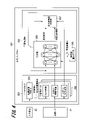
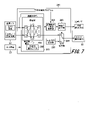
- FIG. 7 is a schematic diagram showing an example of the software configuration of the learning device calculation program 261 executed by the learning type control device 2 in the robot control system 100.
- the CPU of the control device 21 expands and executes the learner calculation program 261 stored in the storage device 24 in the RAM.
- the calculation processing unit 263, the environmental condition matching degree calculation unit 265, the control amount adjustment unit 266, the stop command output unit 267, and the stop command output unit 267 is configured to be provided as a software module.
- the arithmetic processing unit 263 When the camera image and the robot joint angle are input via the communication interface 22, the arithmetic processing unit 263 outputs an estimated image that reproduces the camera image and an estimated motion command that estimates the target joint angle of the working robot 6.
- a learning device 264 for outputting is provided.
- a neural network can be applied to the learner 264 in the same manner as the learner 256.
- the arithmetic processing unit 263 applies the weight value of the learner weight data 262 generated by the learning program 251 of FIG. 4 to the learner 264. do.
- the learner 264 performs arithmetic processing (inference) based on the camera image and the robot joint angle, and generates an estimated motion command.
- the arithmetic processing unit 263 outputs the estimation operation command inferred by the learning device 264 to the output switching unit 268 as a control signal of the working robot 6, and outputs the estimated image to the environmental condition matching degree calculation unit 265.
- the environmental condition matching degree calculation unit 265 describes the environmental condition of the robot device 1 when the learner 256 machine-learns the operation command of the robot device 1 based on the camera image of the camera 8, and the current environmental condition of the robot device 1. The degree of coincidence with is calculated, and the calculation result is output to the control amount adjusting unit 266.
- the control amount adjusting unit 266 (an example of the adjusting unit) adjusts the content of the operation command of the robot device 1 and / or the setting of the camera 8 according to the calculation result of the environmental condition matching degree calculation unit 265, and adjusts the adjustment result. It is output to the robot control device 5 via the communication interface 22. Further, the control amount adjusting unit 266 outputs a switching signal to the output switching unit 268 based on the difference between the estimated image that reproduces the camera image of the camera 8 output by the learner 256 and the current camera image of the camera 8. do.
- the output switching unit 268 robotically operates either the operation command (estimated operation command) estimated by the learner 264 or the stop command output by the stop command output unit 267 based on the switching signal of the control amount adjusting unit 266. As a command, it is output to the robot control device 5 via the communication interface 22.
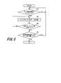
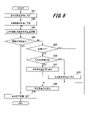
- FIG. 8 is a flowchart showing a procedure example of a method (calculation step, adjustment step) in which the learner calculation program 261 calculates the degree of agreement of the environmental conditions of the robot device 1 to adjust the control amount in the robot control system 100.
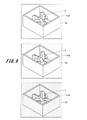
- FIG. 9 is a schematic diagram showing a method in which the environmental condition matching degree calculation unit 265 calculates the matching degree of the environmental condition of the robot device 1 in the robot control system 100.
- FIG. 9 shows an image of the work object 4 piled up in bulk in the carry-in tray 32.
- All the processing steps of FIG. 8 are executed at predetermined sampling timings in the learning type control device 2. Further, the RAM of the control device 21 stores the luminous flux correction amount of the illumination light of the illumination device 7 set in each of steps S22 and S27 and S28. The control device 21 calls the luminous flux correction amount of the illumination light stored in the RAM when adjusting the brightness (illuminance) around the working position of the robot device 1 as an environmental condition of the robot device 1 described later.
- the control amount adjusting unit 266 of the learner calculation program 261 outputs a switching instruction to the output switching unit 268 so that the operation command to the working robot 6 becomes the output of the stop command output unit 267.
- the working robot 6 is stopped (S21). Until the brightness adjustment of the lighting device 7 to be changed in steps S22 to S29, which will be described later, is completed, the working robot 6 operates improperly because the estimated operation command of the learner 264 is inappropriate. In order to prevent this, the learning device calculation program 261 outputs a stop command to the communication interface 22 to stop the working robot 6.
- the control amount adjusting unit 266 positively sets the luminous flux change amount so as to brighten the luminous flux of the illumination light of the illumination device 7 by a predetermined amount from the present (S22). For example, by setting the voltage applied to the lighting device 7 to a value larger by a predetermined amount based on the positive luminous flux change amount, the illumination light of the lighting device 7 becomes brighter.
- the relationship between the luminous flux of the illumination light of the illumination device 7 and the applied voltage is stored in advance in the ROM or the storage device 24 in the form of a correlation formula or a reference table.
- the environmental condition matching degree calculation unit 265 calculates an error between the camera image acquired from the camera 8 and the estimated image output by the learner 264 (S23).
- the environmental condition of the camera image acquired by the camera 8 when the learner weight data 262 applied to the learner 264 is machine-learned is an environmental condition like the image Im1 shown in the upper part of FIG. 9 (condition where the surroundings are bright).
- the estimated image output by the learner 264 is a bright image as in the image Im1 in the upper part of FIG.
- the periphery of the work object 4 when the learner 256 is machine-learned is dark, the camera image acquired by the camera 8 becomes a slightly dark image as shown in the image Im2 in the middle of FIG.
- the neural network estimates to reproduce the machine-learned camera image even under such environmental conditions, the estimated image output by the learner 264 is the image Im1 in the upper part of FIG. The image will be bright as well.
- the difference image Imd as shown in the lower part of FIG. 9 is obtained. .. If there is no difference, the whole image (all pixels) is black. However, if the current environmental conditions are different from the environmental conditions at the time of machine learning by the learner 256, the difference in the environmental conditions appears as an image as shown in the lower part of FIG.
- the environmental condition matching degree calculation unit 265 calculates and outputs the total of the output values (error amount) of each pixel in the difference image Imd as shown in the lower part of FIG. 9 as an error between the camera image and the estimated image. The smaller the total of the output values of each pixel in the difference image Imd, the higher the degree of matching between the camera image and the estimated image.
- control amount adjusting unit 266 determines whether or not the error calculated by the environmental condition agreement degree calculation unit 265 in step S23 is equal to or less than a predetermined value (S24). Then, when the error is equal to or less than a predetermined value (YES in S24), the control amount adjusting unit 266 machine-learns the learner weight data 262 to which the environmental condition at the time of generating the estimated operation command is applied to the learner 264. It is determined that the processing is almost the same as that at the time of the above, and the process proceeds to step S30.
- control amount adjusting unit 266 determines that the environmental conditions are not the same when the learner 256 performs machine learning and when the learner 264 infers. The process proceeds to step S25.
- the control amount adjusting unit 266 determines whether or not the error calculated in step S23 is larger than the error calculated before that (for example, the previous sampling timing) (S25). .. Then, when the error is expanded (YES in S25), the control amount adjusting unit 266 applies the luminous flux change amount set in step S22 to the lighting device 7 (makes the lighting device 7 brighter or darker). , It is determined that the current environmental condition deviates from the environmental condition at the time of machine learning the learner weight data 262, and the process proceeds to step S26. On the other hand, if the error does not increase with the luminous flux change amount set in step S22 (NO in S25), the control amount adjustment unit 266 advances the process to step S29.
- the control amount adjusting unit 266 determines whether or not the light flux change amount is correct, that is, whether or not the illumination light is corrected in the direction of brightening or darkening (S26).
- the control amount adjusting unit 266 makes the luminous flux change amount negative, that is, dims the illumination light of the illuminating device 7 by a predetermined luminous flux change amount. (S27).
- the control amount adjusting unit 266 makes the luminous flux change amount positive, that is, brightens the illumination light of the illuminating device 7 by a predetermined luminous flux change amount. (S28). After the processing of step S27 or S28, the control amount adjusting unit 266 advances the processing to step S29.
- control amount adjusting unit 266 informs the robot control device 5 via the communication interface 22 so that the brightness of the illumination light of the illumination device 7 changes by the amount of the luminous flux change set in steps S22, S27 or S28.
- the luminous flux change command is output (S29).
- the control amount adjusting unit 266 returns the processing to step S23, and continues adjusting the brightness of the lighting device 7 so that the current environmental conditions and the environmental conditions at the time of machine learning by the learner 256 match. do.
- the control amount adjusting unit 266 outputs a switching signal so that the estimated operation command of the learner 264 is output as an operation command to the robot device 1.
- the setting is made, a switching instruction is output to the output switching unit 268, and a series of processing is completed (S30).
- the learning type control device 2 outputs the adjusted operation command of the robot device 1 to the robot control device 5 via the communication interface 22.
- the robot control device 5 generates a control command of the robot device 1 based on the adjusted operation command of the robot device 1 received from the learning type control device 2, and outputs the control command to the robot device 1 via the control interface 53.
- the robot device 1 operates according to a control command generated based on the adjusted operation command received from the robot control device 5 (operation step).
- the camera image, the robot joint angle, the estimated image, and the estimated motion command are linked to each other by the connection of each neuron of the neural network constituting the learner 264. Therefore, when the estimated image output by the learning device 264 matches the camera image (the error is equal to or less than a predetermined value), the content of the estimated operation command output by the learning device 264 is the operation command of the learning data 252. It can be judged that it is the same as. On the other hand, when the estimated image of the learning device 264 does not match the camera image, it can be determined that the content of the estimated operation command of the learning device 264 is not the same as the operation command of the learning data 252. In this case, the learning type control device 2 changes the brightness of the illumination light of the lighting device 7 so that the learning environmental condition of the learning device 256 and the current environmental condition match, so that the working robot 6 can perform the work robot 6. It will work properly.
- the estimated image output by the learner 264 is an image that reflects only the state of the work object 4 from which the momentary disturbance is removed, so that it is not affected by the momentary disturbance. Therefore, when the current camera image (environmental condition) matches the estimated image (environmental condition) at the time of learning of the learning device 256, the environmental condition matching degree calculation unit 265 is more accurate and the content of the estimated operation command is for learning. It can be determined that it is the same as the operation command of the data 252.
- the learning device 256 outputs an estimated image based on the camera image of the camera 8 at the time of learning. It is not limited to the estimated image to be output.
- the information representing the environment at the time of learning the camera image obtained by the camera 8 at the time of learning or the distance measurement data of the distance measuring device described later may be used. That is, the environment condition matching degree calculation unit 265 outputs the output of the environment sensor (camera 8, distance measuring device) when the learner 264 (learned model) learns the operation command of the robot device 1, and the current environment sensor.
- the output may be compared to calculate the degree of agreement between the environmental condition of the robot device 1 at the time of learning and the current environmental condition of the robot device 1. For example, when a camera image is used as information representing an environment at the time of learning, a camera image closest to the average of a plurality of camera images from a plurality of camera images based on the information of each pixel of a plurality of camera images, or a camera image closest to the average of a plurality of camera images. Camera images corresponding to the median values of multiple camera images can be used.
- the learning type control device 2 can adjust the content of the operation command and / or the setting of the environment sensor so that the current environmental condition matches the environmental condition at the time of learning. ..
- the inference accuracy of the motion command of the trained model machine-learned to generate the motion command of the robot device 1 according to the output of the environment sensor is improved, and the learning type control device 2 is an appropriate motion command for the robot device. Can be output.
- the magnitude of the luminous flux change amount set in steps S22, S27 or S28 of FIG. 8 is not a fixed value, and the magnitude of the luminous flux change amount is set in proportion to the magnitude of the error between the camera image and the estimated image, for example. It may be configured as follows. Further, the control amount adjusting unit 266 adjusts the brightness (brightness) and color (saturation) of the acquired image of the camera 8 by outputting a command for physically changing the brightness of the illumination light by the lighting device 7. However, other methods may be used. For example, the control amount adjusting unit 266 may be configured to change the set value of the camera 8 by software and adjust the image quality (brightness and color) of the acquired image of the camera 8.
- the command output by the control amount adjusting unit 266 is not only a command (change amount) for changing the brightness of the illumination light of the lighting device 7, but also a moving amount of the lighting device moving mechanism 13 for changing the position of the lighting device 7. It may be the amount of movement of the camera moving mechanism 14 that changes the position of the camera 8.
- the control amount adjusting unit 266 may be configured to command the moving direction and the moving amount of the lighting device moving mechanism 13 or the camera moving mechanism 14 by using the gradient of the magnitude of the error between the estimated image and the camera image. ..
- control amount adjusting unit 266 is not limited to the configuration in which the distance from the work object 4 to the camera 8 is physically changed by issuing a command to the camera moving mechanism 14.
- the control amount adjustment unit 266 adjusts the size of the work object 4 captured in the camera image by setting the zoom function (zoom in or zoom out) of the camera 8, that is, by changing the focal length of the optical system. You may do so.
- the movement amount of the camera 8 may be changed by the camera movement mechanism 14 and the setting of the zoom function of the camera 8 may be changed at the same time.
- control amount is not only adjusted by the method shown in FIG. 8, but a learner for learning and calculating the change amount may be prepared separately from the learner 264.
- the control amount adjusting unit 266 includes a learning device (not shown) inside, causes the learning device to learn the relationship between the learning data 252 and the change amount, and uses the learning result of the learning device to correct the light beam and illuminate. It may be configured to adjust the movement amount of the camera 8 by the device movement mechanism 13 or the camera set value. Further, the learning device inside the control amount adjusting unit 266 may be configured to adjust the moving amount of the camera 8 by the camera moving mechanism 14 and the perspective setting (enlargement / reduction) of the camera 8.
- the determination of the magnitude of the error between the camera image and the estimated image shown in steps S23 and S24 of FIG. 8 is not limited to the configuration executed before the operation of the working robot 6.
- the processing of steps S23 to S29 is configured to be performed periodically, and the environmental conditions are changed even during the operation of the working robot 6. It may be configured as follows.
- the environment sensor for measuring the environmental conditions of the robot device 1 is not limited to the camera 8, and a distance measuring device using optics or radio waves may be used.
- a distance measuring device using optics or radio waves may be used.
- LIDAR Light Detection and Ranging, Laser Imaging Detection and Ranging
- the environmental conditions are measured by measuring the shape (reflection signal) of the work object 4 and its surrounding objects. It may be configured.
- the shape of the object around the work object 4 is, for example, the shape of a tray for accommodating the work object 4, a transport line, or the like.
- the learner 256, 264 When a distance measuring device is used for the environment sensor, the learner 256, 264 performs a predetermined disturbance removal process (noise removal, etc.) on the reflected signal (distance measuring data) received by the distance measuring device by projecting light on an object.
- the estimated distance measurement data is output as a reproduction signal.
- the ranging data is point cloud data in which the reflected signal obtained from the object and the position where the reflected signal is obtained are associated with each other.
- the working robot 6 is taken as an example of the robot main body, but the robot main body may be a movable self-supporting robot that provides a service.
- the self-supporting robot is equipped with an environment sensor. Further, in the self-supporting robot, peripheral devices are attached to the self-supporting robot itself.
- the environment sensor may be installed in an environment (building) where the self-supporting robot moves.
- the robot control system (robot control system 100) according to the first embodiment includes a robot device (robot device 1) and an environmental sensor (camera 8, distance measuring device) that acquires the environmental conditions of the robot device.
- the current output of the environment sensor is input to the trained model (learner 264) that has undergone machine learning to generate the operation command of the robot device corresponding to the output of the environment sensor, and is output from the trained model.
- the above control device calculates the degree of agreement between the environmental condition of the robot device when the trained model machine-learns the operation command of the robot device and the current environmental condition of the robot device. Adjustment to adjust the content of the operation command of the robot device and / or the setting of the environment sensor based on the calculation results of the environmental condition matching degree calculation unit (environmental condition matching degree calculation unit 265) and the environmental condition matching degree calculation unit. A unit (control amount adjusting unit 266) is provided.
- the environmental conditions when the trained model that generates the operation command of the robot device is machine-learned by the adjusting unit of the control device, and the current environment. Compare with the conditions and calculate the degree of agreement (difference) between the two environmental conditions. Then, the adjusting unit of the control device determines the content of the operation command of the robot device and / or the environment so that the error between the current environmental condition and the environmental condition at the time of learning becomes a predetermined value or less based on the calculation result of the degree of matching. Adjust the sensor settings.
- the robot device can appropriately perform the work.
- the above configuration eliminates the need for machine learning of a learning model (learner 256) in work situations where the environmental conditions are different for the same work content (for example, work for gripping work objects 4 separately stacked on a certain tray). Therefore, it becomes possible to control the robot device by machine learning with few work situations. Therefore, the time and effort required for machine learning of the learning model can be reduced.
- the trained model (learner 264) is added to the operation command of the robot device corresponding to the output of the environment sensor (camera 8, distance measuring device).
- This is a trained model that has been machine-learned to generate a reproduction signal (estimated image, estimated distance measurement data) of the output of the environment sensor, and when the current output of the environment sensor is input, the environment sensor It is configured to generate an operation command of the robot device (robot device 1) corresponding to the current output and a reproduction signal of the output of the environment sensor at the time of learning.
- the environmental condition matching degree calculation unit determines the difference between the reproduction signal of the output of the environment sensor at the time of training output by the trained model and the current output of the environment sensor as the environment condition. Calculated as the degree of matching of. Further, in the adjustment unit (control amount adjustment unit 266), the difference between the reproduction signal of the output of the environment sensor at the time of training output by the trained model and the current output of the environment sensor becomes a predetermined value or less. As such, the content of the operation command of the robot device and / or the setting of the environment sensor is adjusted.
- the trained model is trained to generate a reproduction signal of the output of the environment sensor in addition to the operation command of the robot device corresponding to the output of the environment sensor. Since the reproduction signal is a signal from which momentary disturbances have been removed, the trained model outputs information that reflects only the state of the work object from which momentary disturbances have been removed, based on the output of the environment sensor. do. Therefore, the environmental condition matching degree calculation unit can more accurately calculate the degree of matching between the environmental condition of the robot device at the time of learning and the current environmental condition of the robot device.
- the robot device includes a robot main body (working robot 6) and peripheral devices arranged in or around the robot main body.
- the peripheral device is a device (lighting device 7) that changes the illuminance inside or around the robot device
- the environment sensor is an optical image including a work object handled by the robot device.
- the environment condition matching degree calculation unit estimates that the trained model (learner 264) estimates from a plurality of image signals at the time of learning as a reproduction signal of the output of the environment sensor at the time of learning. Compares the image with the captured image (camera image) as the current output of the environment sensor, and calculates the difference in brightness, saturation, or size of the work object in the captured image between the estimated image and the captured image. .. Further, the adjusting unit (control amount adjusting unit 266) has an adjustment unit (control amount adjustment unit 266) for peripheral devices so that the difference in brightness and saturation between the estimated image and the captured image or the size of the work object reflected in the captured image is equal to or less than a predetermined value. Adjust the content of the operation command and / or the setting of the environment sensor.
- the brightness, saturation, or work object reflected in the estimated image at the time of training generated by the trained model and the currently captured image of the environment sensor is adjusted so that the difference in the magnitudes of the above is equal to or less than the predetermined value. Therefore, the brightness and saturation of the captured image of the environment sensor during work, or the size of the work object reflected in the captured image is changed in a direction that matches the content at the time of learning. Therefore, the inference accuracy of the operation command of the trained model is improved, and the control device (learning type control device 2) can output an appropriate operation command to the peripheral device and / or set the environment sensor appropriately. can.
- the robot device includes a robot main body (working robot 6) and peripheral devices arranged in or around the robot main body.
- the peripheral device is a first moving mechanism (lighting device moving mechanism 13) or an environmental sensor (lighting device moving mechanism 13) that changes the position of the device (lighting device 7) that changes the illuminance inside or around the robot device.
- It is a second moving mechanism (camera moving mechanism 14) that changes the position of the camera 8), and the environment sensor (camera 8) has a function of obtaining an image signal of an optical image including a work object handled by the robot device. It is composed of.
- the environment condition matching degree calculation unit (environment condition matching degree calculation unit 265) is used as a reproduction signal of the output of the environment sensor at the time of learning, and a plurality of image signals (learning data) at the time of learning by the trained model (learner 264).
- the estimated image estimated from 252) is compared with the captured image (camera image) based on the image signal as the current output of the environment sensor, and the difference in brightness or saturation between the estimated image and the captured image, or the work object. Calculate the difference in the positional relationship with the robot device.
- control amount adjustment unit 266 has peripherals so that the difference in brightness or saturation between the estimated image and the captured image, or the difference in the positional relationship between the work object and the robot device is equal to or less than a predetermined value. Adjust the content of the operation command for the device.
- the difference in brightness or saturation between the estimated image at the time of training generated by the trained model and the currently captured image of the environment sensor, or the position of the work object and the robot device is adjusted so that the difference in the relationship is less than or equal to the predetermined value. Therefore, the brightness or saturation of the captured image of the environment sensor during work, or the positional relationship between the work object and the robot device is changed in a direction that matches the content at the time of learning. Therefore, the inference accuracy of the operation command of the trained model is improved, and the control device (learning type control device 2) can output an appropriate operation command to the peripheral device.
- the arrangement of the transfer line may be changed due to the restrictions on the site.
- the arrangements of the carry-in line 31 and the carry-out tray line 33 are interchanged with those in FIG. 3 (when the carry-in line 31 is in front of the work robot 6 and the carry-out tray line 33 is on the left side of the work robot 6). ..
- the working robot 6 grips the work object 4 bulked in the carry-in tray 32 on the carry-in line 31 in front of the work robot 6.
- the work robot 6 arranges and arranges the work object 4 on the carry-out tray 35 carried out to the left side of the work robot 6, and arranges the work object 4 on the carry-out tray 35 from the left side of the work robot 6 to the work robot 6. It is transported to the carry-out line 34 on the right side of.
- the learning data 252 is separately acquired, and the weight of the learning device 256 is machine-learned by each.
- the reason for machine learning in this way is that when one learner 256 is machine-learned for tasks with significantly different movements, the neural network configuration becomes higher (the number of neurons and the number of layers in the middle layer are large). .. The higher the configuration of the neural network, the less robust it becomes, and there is a possibility that the learner 256 will not be able to output appropriate operation commands.
- Neural networks are said to be easy to overfit (fit only teacher data) when the configuration becomes higher. Further, when the operation of the work is significantly different, there is a concern that an average operation command is output for all the operations. Therefore, it is desirable that the learner 256 is machine-learned for each operation, and the obtained plurality of learner weight data 262 can be appropriately switched according to the current environmental conditions.
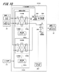
- FIG. 10 is a schematic diagram showing an example of the software configuration of the learning device calculation program executed by the learning type control device 2.
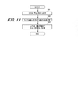
- FIG. 11 is a flowchart showing a procedure example of a method in which a learner arithmetic program selects one learner from a plurality of machine-learned learners.
- the learner calculation program 261A shown in FIG. 10 is different from the learner calculation program 261 of FIG. 7 in that it includes a calculation processing unit 263A in which a plurality of learners are prepared.
- FIG. 10 shows a plurality of different learners. In the following, the two learners are described by changing the sign for each learner weight data applied to each.
- the arithmetic processing unit 263A applies the learner weight data 262a to the learner 264a and applies the learner weight data 262b to the learner 264b.
- the learning devices 264a and 264b output an estimated image that reproduces the plurality of camera images and an estimated operation command of the working robot 6. It is configured as follows.
- the learners 264a and 264b can be configured by using a neural network in the same manner as the learner 264.
- the control amount adjusting unit 266 outputs a switching instruction to the output switching unit 268 so that the operation command to the working robot 6 becomes the output of the stop command output unit 267 (S41).
- the environmental condition matching degree calculation unit 265 calculates the error between the estimated image and the camera image output by the learning devices 264a and 264b, respectively (S42). For example, as described above, a learning device to which the learning result of the operation of gripping the work object 4 stacked separately on the left side of the working robot 6 is applied is stacked separately in front of the learning device 264a and the working robot 6.
- the learning device 264b is a learning device to which the learning result of the operation of gripping the work object 4 is applied.
- the control amount adjusting unit 266 sets and outputs the operation command to the working robot 6 so that the error between the camera image and the estimated image in each of the learning devices 264a and 264b calculated in step S42 is the smallest.
- a switching instruction is output to the switching unit 268 to end a series of processes (S43).
- the control amount adjusting unit 266 switches the output switching unit 268 so that the output of the output switching unit 268 becomes the output of the learner 264a.
- the control amount adjusting unit 266 controls the output switching unit 268 so that the output of the output switching unit 268 becomes the output of the learner 264b. Toggle the switch.
- the collection of the learning data 252 and the machine learning of the learning device weight data 262 applied to the learning device 264 are configured to be separately performed based on environmental conditions other than the difference in the position and posture of the work object 4. You may. For example, the brightness of the illumination light of the lighting device 7 is adjusted, training data 252 is collected in both a bright environment and a dark environment, and two learning device weight data 262 obtained by machine learning are used. You may. Further, learning data 252 is collected for each type (color, shape, etc.) of the work object 4, and the learning device weight data 262 obtained by machine learning according to the type of the work object 4 is used. It may be configured in.
- the adjustment content of the control amount adjusting unit 266 is not limited to the switching of the learning devices 264a and 264b.
- the brightness of the illumination light of the illumination device 7 may be changed as shown in FIG. 7. In this way, the learning device that best matches the environmental conditions may be selected while adjusting the operation commands to the peripheral devices of the working robot 6.
- the robot control system 100 has a plurality of learning devices that have been machine-learned under a plurality of environmental conditions, and each learning device compares the environmental conditions at the time of machine learning with the current environmental conditions, and a plurality of learning devices. Controls to select the learning device that best matches the environmental conditions from the devices. As a result, the operation command of the robot device 1 most suitable for the current environment and / or the setting of the environment sensor can be output, and the robot device 1 can be made to execute an appropriate operation.
- the control device outputs the environment sensor (camera 8, distance measuring device) for each different environmental condition. It is configured to include a plurality of trained models (learners 264a to 264b) that have been machine-learned to generate an operation command of the robot device (robot device 1) corresponding to the above. Then, the environmental condition matching degree calculation unit (environmental condition matching degree calculation unit 265) compares the output of the plurality of trained models based on the output of the environment sensor at the time of learning with the current output of the environment sensor, and a plurality of.
- the adjusting unit calculates the degree of agreement between the environmental conditions of the robot device when the trained model performs machine learning and the current environmental conditions of the robot device. Further, the adjusting unit (control amount adjusting unit 266) outputs from the trained model having the highest degree of matching of the environmental conditions among a plurality of trained models based on the calculation result of the environmental condition matching degree calculation unit. Control so that the operation command is transmitted to the robot device.
- the robot uses an operation command generated by the trained model closest to the current environmental conditions from among the plurality of trained models.
- the operation of the device can be controlled. Therefore, the robot control system can cause the robot device to appropriately perform an operation by using the trained model closest to the current environmental conditions. Therefore, the work accuracy of the robot device is improved.
- ⁇ Third embodiment> As a third embodiment of the present invention, a method of automatically classifying the environmental conditions of newly acquired learning data for a plurality of learning devices that have been machine-learned in the past will be described with reference to FIG.
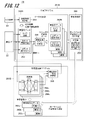
- FIG. 12 is a schematic diagram showing an example of the software configuration of the learning program and the learning device calculation program executed by the learning type control device in the robot control system according to the third embodiment.
- the learning type control device 2B shown in FIG. 12 includes a learning program 251B to which the environmental condition label addition unit 258 is added, and a learning device calculation program 261B.
- the other configurations of the learning type control device 2B the same configurations as those of the learning type control device 2 can be adopted.
- unique information is added in advance to each of the learner weight data 262a to 262c applied to the learners 264a to 264c.
- the unique information is metadata or the like in which information representing the unique number of the robot device 1 or environmental conditions is recorded.
- the unique information is shown as “environment (1)” to “environment (3)”.
- the learner weight data 262a to 262c and the learner 264a to 264c are not distinguished from each other, they are described as the learner weight data 262 and the learner 264.
- the detailed description of the control amount adjusting unit 266, the stop command output unit 267, and the output switching unit 268 of the learner calculation program 261B will be omitted.
- the learning device calculation program 261B calculates each of the learning devices 264a to 264c to which the learning device weight data 262a to 262c to which the unique information is added is applied, and a plurality of estimated images reproduced by the learning devices 264a to 264c are generated. It is output to the environment condition matching degree calculation unit 265.
- the environmental condition matching degree calculation unit 265 calculates the degree of matching between the environmental conditions when the learning devices 264a to 264c perform machine learning and the environmental conditions of the learning data 252 collected by the data collecting unit 253B, and the most. Identify the learner weight data 262 that match the environmental conditions. Then, the environmental condition matching degree calculation unit 265 outputs the unique information of the specified learner weight data 262 to the environmental condition label addition unit 258 of the data collection unit 253. For example, as shown in FIG. 12, the environmental condition matching degree calculation unit 265 estimates each of the three learner weight data 262a to 262c to which the unique information of "environment (1)" to "environment (3)” is added. Compare the image with the current camera image.
- the environmental condition matching degree calculation unit 265 determines that the learning device weight data 262a corresponding to the estimated image with the most matching environmental conditions is the learning device weight data 262a, the learning device weight data 262a is unique.
- the information "environment (1)" is output.
- the environmental condition label addition unit 258 of the learning program 251B records the unique information (label) output by the environmental condition matching degree calculation unit 265 when the collected learning data 252 is recorded in the storage device 24, as the learning data 252. To add to.
- the learning processing unit 255 uses a plurality of learning data 252B having the same unique information from the newly recorded learning data 252 to learn the learning device 256 (FIG. 4) again, and the learning device 256 (FIG. 4) is unique.
- the learner weight data 262 corresponding to the information is updated. For example, as shown in FIG. 12, the learning device 256 is machine-learned again using the plurality of learning data 252B to which the unique information of the "environment (1)" is added, and the weight of the obtained learning device 256 is obtained. Is applied to the learner weight data 262a to which the unique information of "environment (1)" is added.
- the inference accuracy of the learning device 264 can be improved and the robot device 1 can be operated appropriately.
- the learning data 252 and the learning device weight data 262 thus obtained may be configured to be shared with the learning type control device at another site via the network 3.
- the unique information of the robot device 1 when the user performs machine learning by the learning device 256 by the input device 23 is associated with the learning device weight data 262 and recorded in the storage device 24.
- the unique information of the robot device 1 is registered in advance in the learning type control device 2B, and the learning device weight data 262 created when the learning processing unit 255 performs machine learning by the learning device 256 is associated with the unique information and stored in the storage device. It may be recorded in 24.
- the learning device weight data 262 of a certain amount is created, the learning device weight data 262 can be efficiently updated by automating the classification of the learning data by the method using the unique information of the present embodiment.
- each of the above-described embodiments describes the configuration of the robot control system in detail and concretely in order to explain the present invention in an easy-to-understand manner, and is not necessarily limited to the one including all the components described above.
- each of the above configurations, functions, processing units, etc. may be realized by hardware, for example, by designing a part or all of them by an integrated circuit.
- FPGA Field Programmable Gate Array
- ASIC Application Specific Integrated Circuit
Landscapes
- Engineering & Computer Science (AREA)
- Robotics (AREA)
- Mechanical Engineering (AREA)
- Manipulator (AREA)
Priority Applications (1)
| Application Number | Priority Date | Filing Date | Title |
|---|---|---|---|
| US18/033,814 US20230390935A1 (en) | 2020-11-10 | 2021-08-26 | Robot control system, robot control method, and program |
Applications Claiming Priority (2)
| Application Number | Priority Date | Filing Date | Title |
|---|---|---|---|
| JP2020186988A JP7492440B2 (ja) | 2020-11-10 | 2020-11-10 | ロボット制御システム、ロボット制御方法及びプログラム |
| JP2020-186988 | 2020-11-10 |
Publications (1)
| Publication Number | Publication Date |
|---|---|
| WO2022102207A1 true WO2022102207A1 (ja) | 2022-05-19 |
Family
ID=81601054
Family Applications (1)
| Application Number | Title | Priority Date | Filing Date |
|---|---|---|---|
| PCT/JP2021/031322 Ceased WO2022102207A1 (ja) | 2020-11-10 | 2021-08-26 | ロボット制御システム、ロボット制御方法及びプログラム |
Country Status (3)
| Country | Link |
|---|---|
| US (1) | US20230390935A1 (enExample) |
| JP (1) | JP7492440B2 (enExample) |
| WO (1) | WO2022102207A1 (enExample) |
Cited By (1)
| Publication number | Priority date | Publication date | Assignee | Title |
|---|---|---|---|---|
| WO2025169341A1 (ja) * | 2024-02-07 | 2025-08-14 | 株式会社Nttドコモ | ネットワーク構成要素及び無線通信方法 |
Families Citing this family (5)
| Publication number | Priority date | Publication date | Assignee | Title |
|---|---|---|---|---|
| DE112021007813T5 (de) * | 2021-08-20 | 2024-03-28 | Fanuc Corporation | Vorrichtung zum lehren von position und haltung für einen roboter zum greifen eines werkstücks, robotersystem und verfahren |
| CN117957095A (zh) * | 2021-09-16 | 2024-04-30 | X开发有限责任公司 | 从演示中学习确定机器人感知运动 |
| KR102709710B1 (ko) * | 2022-07-25 | 2024-09-26 | 주식회사 아임토리 | 스마트 팩토리의 행동개선 솔루션을 제공하는 장치 및 방법 |
| JPWO2024111303A1 (enExample) * | 2022-11-22 | 2024-05-30 | ||
| US20250249592A1 (en) * | 2024-02-02 | 2025-08-07 | Intrinsic Innovation Llc | Pose correction for robotics |
Citations (4)
| Publication number | Priority date | Publication date | Assignee | Title |
|---|---|---|---|---|
| JP2006320997A (ja) * | 2005-05-18 | 2006-11-30 | Nippon Telegr & Teleph Corp <Ntt> | ロボット行動選択装置及びロボット行動選択方法 |
| JP2018136211A (ja) * | 2017-02-22 | 2018-08-30 | オムロン株式会社 | 環境認識システム及び学習装置 |
| JP2019136807A (ja) * | 2018-02-08 | 2019-08-22 | ファナック株式会社 | 制御装置及び機械学習装置 |
| JP2020110894A (ja) * | 2019-01-16 | 2020-07-27 | 株式会社エクサウィザーズ | 学習済モデル生成装置、ロボット制御装置、及び、プログラム |
Family Cites Families (60)
| Publication number | Priority date | Publication date | Assignee | Title |
|---|---|---|---|---|
| US8559699B2 (en) * | 2008-10-10 | 2013-10-15 | Roboticvisiontech Llc | Methods and apparatus to facilitate operations in image based systems |
| US8504204B2 (en) * | 2010-07-22 | 2013-08-06 | Cognisense Labs, Inc. | Automated positioning of an organic polarized object |
| US9579799B2 (en) * | 2014-04-30 | 2017-02-28 | Coleman P. Parker | Robotic control system using virtual reality input |
| US9272417B2 (en) * | 2014-07-16 | 2016-03-01 | Google Inc. | Real-time determination of object metrics for trajectory planning |
| US10518409B2 (en) * | 2014-09-02 | 2019-12-31 | Mark Oleynik | Robotic manipulation methods and systems for executing a domain-specific application in an instrumented environment with electronic minimanipulation libraries |
| US9492923B2 (en) * | 2014-12-16 | 2016-11-15 | Amazon Technologies, Inc. | Generating robotic grasping instructions for inventory items |
| DE102016015936B8 (de) * | 2015-07-31 | 2024-10-24 | Fanuc Corporation | Vorrichtung für maschinelles Lernen, Robotersystem und maschinelles Lernsystem zum Lernen eines Werkstückaufnahmevorgangs |
| CA3004711C (en) * | 2015-11-13 | 2022-01-11 | Berkshire Grey, Inc. | Sortation systems and methods for providing sortation of a variety of objects |
| ES2924496T3 (es) * | 2016-02-08 | 2022-10-07 | Berkshire Grey Operating Company Inc | Sistemas y métodos para proporcionar el procesamiento de una variedad de objetos empleando planificación de movimiento |
| CN108885715B (zh) * | 2016-03-03 | 2020-06-26 | 谷歌有限责任公司 | 用于机器人抓取的深度机器学习方法和装置 |
| US10322506B2 (en) * | 2016-05-06 | 2019-06-18 | Kindred Systems Inc. | Systems, devices, articles, and methods for using trained robots |
| WO2017199261A1 (en) * | 2016-05-19 | 2017-11-23 | Deep Learning Robotics Ltd. | Robot assisted object learning vision system |
| EP3485370A4 (en) * | 2016-07-18 | 2020-03-25 | Lael Odhner | ASSESSMENT OF ROBOTIC GRIPPING |
| WO2018087546A1 (en) * | 2016-11-08 | 2018-05-17 | Dogtooth Technologies Limited | A robotic fruit picking system |
| US11097417B2 (en) * | 2016-12-20 | 2021-08-24 | Kindred Systems Inc. | Systems, devices, articles and methods for the partition of items |
| JP6951659B2 (ja) * | 2017-05-09 | 2021-10-20 | オムロン株式会社 | タスク実行システム、タスク実行方法、並びにその学習装置及び学習方法 |
| AU2018306475A1 (en) * | 2017-07-25 | 2020-03-05 | Mbl Limited | Systems and methods for operations a robotic system and executing robotic interactions |
| JP2020532440A (ja) * | 2017-09-01 | 2020-11-12 | カリフォルニア大学The Regents of the University of California | オブジェクトをロバストに把持し、ターゲティングするためのロボットシステムおよび方法 |
| US10773382B2 (en) * | 2017-09-15 | 2020-09-15 | X Development Llc | Machine learning methods and apparatus for robotic manipulation and that utilize multi-task domain adaptation |
| JP6695843B2 (ja) * | 2017-09-25 | 2020-05-20 | ファナック株式会社 | 装置、及びロボットシステム |
| US10958895B1 (en) * | 2017-10-04 | 2021-03-23 | Amazon Technologies, Inc. | High speed automated capture of 3D models of packaged items |
| US10792810B1 (en) * | 2017-12-14 | 2020-10-06 | Amazon Technologies, Inc. | Artificial intelligence system for learning robotic control policies |
| US10754318B2 (en) * | 2017-12-21 | 2020-08-25 | X Development Llc | Robot interaction with objects based on semantic information associated with embedding spaces |
| US10919151B1 (en) * | 2018-03-23 | 2021-02-16 | Amazon Technologies, Inc. | Robotic device control optimization using spring lattice deformation model |
| US10766149B2 (en) * | 2018-03-23 | 2020-09-08 | Amazon Technologies, Inc. | Optimization-based spring lattice deformation model for soft materials |
| US11940456B2 (en) * | 2018-09-11 | 2024-03-26 | Becton Dickinson And Company | Robotic sample preparation system for diagnostic testing with automated position learning |
| WO2020056279A1 (en) * | 2018-09-13 | 2020-03-19 | The Charles Stark Draper Laboratory, Inc. | Manipulating fracturable and deformable materials using articulated manipulators |
| US12486061B2 (en) * | 2018-09-26 | 2025-12-02 | Dexterity, Inc. | Robotic kitting system |
| US11007642B2 (en) * | 2018-10-23 | 2021-05-18 | X Development Llc | Machine learning methods and apparatus for automated robotic placement of secured object in appropriate location |
| JP7205752B2 (ja) * | 2018-11-09 | 2023-01-17 | オムロン株式会社 | ロボット制御装置、ロボット制御方法、及びロボット制御プログラム |
| US11839983B2 (en) * | 2018-11-27 | 2023-12-12 | Ocado Innovation Limited | Systems and methods for robotic grasp verification |
| US11148289B1 (en) * | 2019-01-08 | 2021-10-19 | Amazon Technologies, Inc. | Entanglement end effector for autonomous object retrieval |
| US10549928B1 (en) * | 2019-02-22 | 2020-02-04 | Dexterity, Inc. | Robotic multi-item type palletizing and depalletizing |
| US11806880B2 (en) * | 2019-02-22 | 2023-11-07 | Dexterity, Inc. | Robotic handling of soft products in non-rigid packaging |
| CN113840694A (zh) * | 2019-03-11 | 2021-12-24 | 右手机器人股份有限公司 | 拾取操作的物品扰动 |
| US11701771B2 (en) * | 2019-05-15 | 2023-07-18 | Nvidia Corporation | Grasp generation using a variational autoencoder |
| US11345030B2 (en) * | 2019-05-28 | 2022-05-31 | Intel Corporation | Methods and apparatus for complex assembly via autonomous robots using reinforcement learning action primitives |
| US11688030B2 (en) * | 2019-06-12 | 2023-06-27 | Frito-Lay North America, Inc. | Shading topography imaging for robotic unloading |
| US11400592B2 (en) * | 2019-08-19 | 2022-08-02 | Wipro Limited | Method and system for task execution in dynamic heterogeneous robotic environment |
| US11345029B2 (en) * | 2019-08-21 | 2022-05-31 | Mujin, Inc. | Robotic multi-gripper assemblies and methods for gripping and holding objects |
| CN112405570A (zh) * | 2019-08-21 | 2021-02-26 | 牧今科技 | 用于夹持和保持物体的机器人多夹持器组件和方法 |
| EP4025394A1 (en) * | 2019-09-07 | 2022-07-13 | Embodied Intelligence, Inc. | Systems and methods for robotic picking and perturbation |
| CN114641378B (zh) * | 2019-09-07 | 2024-09-27 | 具现智能有限公司 | 用于机器人拣选的系统和方法 |
| EP4025395A1 (en) * | 2019-09-07 | 2022-07-13 | Embodied Intelligence, Inc. | Training artificial networks for robotic picking |
| WO2021046530A1 (en) * | 2019-09-07 | 2021-03-11 | Embodied Intelligence, Inc. | Three-dimensional computer vision system for robotic devices |
| US12236340B2 (en) * | 2019-09-13 | 2025-02-25 | Osaro | Computer-automated robot grasp depth estimation |
| US12493792B2 (en) * | 2019-10-24 | 2025-12-09 | Nvidia Corporation | Reinforcement learning of tactile grasp policies |
| US11839986B2 (en) * | 2019-10-25 | 2023-12-12 | Ocado Innovation Limited | Systems and methods for active perception and coordination between robotic vision systems and manipulators |
| US11701776B2 (en) * | 2019-10-25 | 2023-07-18 | Dexterity, Inc. | Robotic kitting machine |
| US11772262B2 (en) * | 2019-10-25 | 2023-10-03 | Dexterity, Inc. | Detecting slippage from robotic grasp |
| US10906188B1 (en) * | 2019-10-25 | 2021-02-02 | Dexterity, Inc. | Singulation of arbitrary mixed items |
| US11724401B2 (en) * | 2019-11-13 | 2023-08-15 | Nvidia Corporation | Grasp determination for an object in clutter |
| US12109701B2 (en) * | 2019-11-20 | 2024-10-08 | Nvidia Corporation | Guided uncertainty-aware policy optimization: combining model-free and model-based strategies for sample-efficient learning |
| US11440196B1 (en) * | 2019-12-17 | 2022-09-13 | X Development Llc | Object association using machine learning models |
| US11587302B2 (en) * | 2019-12-17 | 2023-02-21 | X Development Llc | Shared dense network with robot task-specific heads |
| US11318499B2 (en) * | 2019-12-19 | 2022-05-03 | Nimble Robotics, Inc. | Robotic system having shuttle |
| JP2021146452A (ja) * | 2020-03-19 | 2021-09-27 | 株式会社東芝 | ハンドリング装置、制御装置、および制御プログラム |
| US11731271B2 (en) * | 2020-06-30 | 2023-08-22 | Microsoft Technology Licensing, Llc | Verbal-based focus-of-attention task model encoder |
| US11654564B2 (en) * | 2020-09-10 | 2023-05-23 | Fanuc Corporation | Efficient data generation for grasp learning with general grippers |
| US12070860B2 (en) * | 2020-09-14 | 2024-08-27 | Intelligrated Headquarters, Llc | Machine learning based decision making for robotic item handling |
-
2020
- 2020-11-10 JP JP2020186988A patent/JP7492440B2/ja active Active
-
2021
- 2021-08-26 WO PCT/JP2021/031322 patent/WO2022102207A1/ja not_active Ceased
- 2021-08-26 US US18/033,814 patent/US20230390935A1/en active Pending
Patent Citations (4)
| Publication number | Priority date | Publication date | Assignee | Title |
|---|---|---|---|---|
| JP2006320997A (ja) * | 2005-05-18 | 2006-11-30 | Nippon Telegr & Teleph Corp <Ntt> | ロボット行動選択装置及びロボット行動選択方法 |
| JP2018136211A (ja) * | 2017-02-22 | 2018-08-30 | オムロン株式会社 | 環境認識システム及び学習装置 |
| JP2019136807A (ja) * | 2018-02-08 | 2019-08-22 | ファナック株式会社 | 制御装置及び機械学習装置 |
| JP2020110894A (ja) * | 2019-01-16 | 2020-07-27 | 株式会社エクサウィザーズ | 学習済モデル生成装置、ロボット制御装置、及び、プログラム |
Cited By (1)
| Publication number | Priority date | Publication date | Assignee | Title |
|---|---|---|---|---|
| WO2025169341A1 (ja) * | 2024-02-07 | 2025-08-14 | 株式会社Nttドコモ | ネットワーク構成要素及び無線通信方法 |
Also Published As
| Publication number | Publication date |
|---|---|
| JP2022076572A (ja) | 2022-05-20 |
| US20230390935A1 (en) | 2023-12-07 |
| JP7492440B2 (ja) | 2024-05-29 |
Similar Documents
| Publication | Publication Date | Title |
|---|---|---|
| JP7492440B2 (ja) | ロボット制御システム、ロボット制御方法及びプログラム | |
| CN114080583B (zh) | 视觉教导和重复移动操纵系统 | |
| US11407111B2 (en) | Method and system to generate a 3D model for a robot scene | |
| JP5200772B2 (ja) | ロボット装置の制御方法及びロボット装置 | |
| JP5806301B2 (ja) | ロボットシステムにおける物理的な物体の選択のための方法 | |
| KR102432370B1 (ko) | 피킹 로봇을 위한 비젼 분석 장치 | |
| CN111319039B (zh) | 机器人 | |
| CN113172629B (zh) | 一种基于时序触觉数据处理的物体抓取方法 | |
| JP7117237B2 (ja) | ロボット制御装置、ロボットシステム及びロボット制御方法 | |
| US20210170579A1 (en) | Robot controller that controls robot, learned model, method of controlling robot, and storage medium | |
| JP2022076572A5 (enExample) | ||
| WO2020241037A1 (ja) | 学習装置、学習方法、学習プログラム、自動制御装置、自動制御方法および自動制御プログラム | |
| US20240308082A1 (en) | Apparatus and method for controlling robotic manipulators | |
| US11559888B2 (en) | Annotation device | |
| KR20210092875A (ko) | 로봇과 카메라 간 좌표값 보정 장치 및 보정 방법 | |
| JP2020025992A (ja) | 制御装置、制御方法、およびプログラム | |
| US20230321826A1 (en) | Method for Controlling a Robotic Device | |
| NL2035240B1 (en) | Method and systems for compensating for a deviation in a plurality of workingposes of a manipulator of an autonomous charging device | |
| WO2023286138A1 (ja) | ロボット制御システム、ロボットシステム、ロボット制御方法、およびロボット制御プログラム | |
| JPH06106490A (ja) | 制御装置 | |
| JP4193098B2 (ja) | トラッキング装置、トラッキング装置のトラッキング方法及びロボット装置 | |
| JP7737865B2 (ja) | 動作指令生成装置および動作指令生成方法 | |
| Chen et al. | Robotic grasp control policy with target pre-detection based on deep Q-learning | |
| Marturi et al. | A real-time tracking and optimised gaze control for a redundant humanoid robot head | |
| JP7628914B2 (ja) | 制御システム及び制御方法 |
Legal Events
| Date | Code | Title | Description |
|---|---|---|---|
| 121 | Ep: the epo has been informed by wipo that ep was designated in this application |
Ref document number: 21891455 Country of ref document: EP Kind code of ref document: A1 |
|
| NENP | Non-entry into the national phase |
Ref country code: DE |
|
| 122 | Ep: pct application non-entry in european phase |
Ref document number: 21891455 Country of ref document: EP Kind code of ref document: A1 |