WO2022097752A1 - Method for producing eyeglass lens - Google Patents
Method for producing eyeglass lens Download PDFInfo
- Publication number
- WO2022097752A1 WO2022097752A1 PCT/JP2021/041074 JP2021041074W WO2022097752A1 WO 2022097752 A1 WO2022097752 A1 WO 2022097752A1 JP 2021041074 W JP2021041074 W JP 2021041074W WO 2022097752 A1 WO2022097752 A1 WO 2022097752A1
- Authority
- WO
- WIPO (PCT)
- Prior art keywords
- metal
- layer
- particles
- spectacle lens
- film
- Prior art date
Links
- 238000004519 manufacturing process Methods 0.000 title claims abstract description 38
- 229910052751 metal Inorganic materials 0.000 claims abstract description 147
- 239000002184 metal Substances 0.000 claims abstract description 147
- 238000000034 method Methods 0.000 claims abstract description 57
- 238000010894 electron beam technology Methods 0.000 claims abstract description 33
- 239000002923 metal particle Substances 0.000 claims abstract description 26
- 238000007740 vapor deposition Methods 0.000 claims description 76
- 239000002245 particle Substances 0.000 claims description 54
- BASFCYQUMIYNBI-UHFFFAOYSA-N platinum Chemical compound [Pt] BASFCYQUMIYNBI-UHFFFAOYSA-N 0.000 claims description 33
- BQCADISMDOOEFD-UHFFFAOYSA-N Silver Chemical compound [Ag] BQCADISMDOOEFD-UHFFFAOYSA-N 0.000 claims description 26
- 229910052709 silver Inorganic materials 0.000 claims description 26
- 239000004332 silver Substances 0.000 claims description 26
- 229910052697 platinum Inorganic materials 0.000 claims description 16
- 238000011282 treatment Methods 0.000 claims description 15
- KDLHZDBZIXYQEI-UHFFFAOYSA-N Palladium Chemical compound [Pd] KDLHZDBZIXYQEI-UHFFFAOYSA-N 0.000 claims description 11
- PXHVJJICTQNCMI-UHFFFAOYSA-N Nickel Chemical compound [Ni] PXHVJJICTQNCMI-UHFFFAOYSA-N 0.000 claims description 9
- 230000001678 irradiating effect Effects 0.000 claims description 7
- 239000010931 gold Substances 0.000 claims description 6
- 239000010949 copper Substances 0.000 claims description 5
- PCHJSUWPFVWCPO-UHFFFAOYSA-N gold Chemical compound [Au] PCHJSUWPFVWCPO-UHFFFAOYSA-N 0.000 claims description 5
- 229910052737 gold Inorganic materials 0.000 claims description 5
- 229910052763 palladium Inorganic materials 0.000 claims description 5
- 239000010936 titanium Substances 0.000 claims description 5
- RYGMFSIKBFXOCR-UHFFFAOYSA-N Copper Chemical compound [Cu] RYGMFSIKBFXOCR-UHFFFAOYSA-N 0.000 claims description 4
- RTAQQCXQSZGOHL-UHFFFAOYSA-N Titanium Chemical compound [Ti] RTAQQCXQSZGOHL-UHFFFAOYSA-N 0.000 claims description 4
- 229910052793 cadmium Inorganic materials 0.000 claims description 4
- BDOSMKKIYDKNTQ-UHFFFAOYSA-N cadmium atom Chemical compound [Cd] BDOSMKKIYDKNTQ-UHFFFAOYSA-N 0.000 claims description 4
- 239000010941 cobalt Substances 0.000 claims description 4
- 229910017052 cobalt Inorganic materials 0.000 claims description 4
- GUTLYIVDDKVIGB-UHFFFAOYSA-N cobalt atom Chemical compound [Co] GUTLYIVDDKVIGB-UHFFFAOYSA-N 0.000 claims description 4
- 229910052802 copper Inorganic materials 0.000 claims description 4
- 238000001035 drying Methods 0.000 claims description 4
- QSHDDOUJBYECFT-UHFFFAOYSA-N mercury Chemical compound [Hg] QSHDDOUJBYECFT-UHFFFAOYSA-N 0.000 claims description 4
- 229910052753 mercury Inorganic materials 0.000 claims description 4
- 229910052759 nickel Inorganic materials 0.000 claims description 4
- 229910052719 titanium Inorganic materials 0.000 claims description 4
- HCHKCACWOHOZIP-UHFFFAOYSA-N Zinc Chemical compound [Zn] HCHKCACWOHOZIP-UHFFFAOYSA-N 0.000 claims description 3
- 229910052725 zinc Inorganic materials 0.000 claims description 3
- 239000011701 zinc Substances 0.000 claims description 3
- 230000015572 biosynthetic process Effects 0.000 abstract description 10
- 238000005566 electron beam evaporation Methods 0.000 abstract 1
- 230000008020 evaporation Effects 0.000 abstract 1
- 238000001704 evaporation Methods 0.000 abstract 1
- 239000010410 layer Substances 0.000 description 215
- 239000010408 film Substances 0.000 description 90
- 239000000463 material Substances 0.000 description 74
- 239000000243 solution Substances 0.000 description 46
- 239000000126 substance Substances 0.000 description 23
- 239000005871 repellent Substances 0.000 description 21
- 230000000844 anti-bacterial effect Effects 0.000 description 19
- 229910052731 fluorine Inorganic materials 0.000 description 17
- YCKRFDGAMUMZLT-UHFFFAOYSA-N Fluorine atom Chemical compound [F] YCKRFDGAMUMZLT-UHFFFAOYSA-N 0.000 description 16
- 239000011737 fluorine Substances 0.000 description 16
- 238000010438 heat treatment Methods 0.000 description 16
- XLYOFNOQVPJJNP-UHFFFAOYSA-N water Substances O XLYOFNOQVPJJNP-UHFFFAOYSA-N 0.000 description 16
- 238000011156 evaluation Methods 0.000 description 12
- 150000002739 metals Chemical class 0.000 description 12
- 238000012360 testing method Methods 0.000 description 10
- -1 for example Substances 0.000 description 9
- 230000000052 comparative effect Effects 0.000 description 8
- 239000002346 layers by function Substances 0.000 description 8
- IVSZLXZYQVIEFR-UHFFFAOYSA-N m-xylene Chemical group CC1=CC=CC(C)=C1 IVSZLXZYQVIEFR-UHFFFAOYSA-N 0.000 description 8
- 230000003287 optical effect Effects 0.000 description 8
- 239000004033 plastic Substances 0.000 description 8
- 229920003023 plastic Polymers 0.000 description 8
- 239000011347 resin Substances 0.000 description 8
- 229920005989 resin Polymers 0.000 description 8
- 210000005252 bulbus oculi Anatomy 0.000 description 7
- 239000006185 dispersion Substances 0.000 description 7
- 239000007788 liquid Substances 0.000 description 7
- 239000000758 substrate Substances 0.000 description 7
- 238000000427 thin-film deposition Methods 0.000 description 7
- 229910004298 SiO 2 Inorganic materials 0.000 description 6
- 239000000203 mixture Substances 0.000 description 6
- 230000005540 biological transmission Effects 0.000 description 5
- 238000013461 design Methods 0.000 description 5
- 239000012044 organic layer Substances 0.000 description 5
- 238000002360 preparation method Methods 0.000 description 5
- 230000002940 repellent Effects 0.000 description 5
- 239000010409 thin film Substances 0.000 description 5
- 125000001931 aliphatic group Chemical group 0.000 description 4
- 239000000956 alloy Substances 0.000 description 4
- 229910045601 alloy Inorganic materials 0.000 description 4
- 238000000313 electron-beam-induced deposition Methods 0.000 description 4
- 125000004435 hydrogen atom Chemical group [H]* 0.000 description 4
- 238000002347 injection Methods 0.000 description 4
- 239000007924 injection Substances 0.000 description 4
- 239000000843 powder Substances 0.000 description 4
- 229910000077 silane Inorganic materials 0.000 description 4
- 230000003595 spectral effect Effects 0.000 description 4
- 125000004432 carbon atom Chemical group C* 0.000 description 3
- MTHSVFCYNBDYFN-UHFFFAOYSA-N diethylene glycol Chemical compound OCCOCCO MTHSVFCYNBDYFN-UHFFFAOYSA-N 0.000 description 3
- 239000011521 glass Substances 0.000 description 3
- 125000000962 organic group Chemical group 0.000 description 3
- 230000003647 oxidation Effects 0.000 description 3
- 238000007254 oxidation reaction Methods 0.000 description 3
- 238000001228 spectrum Methods 0.000 description 3
- 241000894006 Bacteria Species 0.000 description 2
- VYPSYNLAJGMNEJ-UHFFFAOYSA-N Silicium dioxide Chemical compound O=[Si]=O VYPSYNLAJGMNEJ-UHFFFAOYSA-N 0.000 description 2
- PPBRXRYQALVLMV-UHFFFAOYSA-N Styrene Chemical compound C=CC1=CC=CC=C1 PPBRXRYQALVLMV-UHFFFAOYSA-N 0.000 description 2
- 125000000217 alkyl group Chemical group 0.000 description 2
- 239000007864 aqueous solution Substances 0.000 description 2
- 239000000919 ceramic Substances 0.000 description 2
- 239000003795 chemical substances by application Substances 0.000 description 2
- 150000001875 compounds Chemical class 0.000 description 2
- 238000010586 diagram Methods 0.000 description 2
- 230000000694 effects Effects 0.000 description 2
- 238000005516 engineering process Methods 0.000 description 2
- 229910052736 halogen Inorganic materials 0.000 description 2
- 150000002367 halogens Chemical group 0.000 description 2
- 239000012535 impurity Substances 0.000 description 2
- 150000002484 inorganic compounds Chemical class 0.000 description 2
- 229910010272 inorganic material Inorganic materials 0.000 description 2
- 239000012948 isocyanate Substances 0.000 description 2
- 238000005259 measurement Methods 0.000 description 2
- RVTZCBVAJQQJTK-UHFFFAOYSA-N oxygen(2-);zirconium(4+) Chemical compound [O-2].[O-2].[Zr+4] RVTZCBVAJQQJTK-UHFFFAOYSA-N 0.000 description 2
- 238000005240 physical vapour deposition Methods 0.000 description 2
- 229910052814 silicon oxide Inorganic materials 0.000 description 2
- 238000005245 sintering Methods 0.000 description 2
- 238000010998 test method Methods 0.000 description 2
- 238000001771 vacuum deposition Methods 0.000 description 2
- 230000008016 vaporization Effects 0.000 description 2
- 230000000007 visual effect Effects 0.000 description 2
- 229910001928 zirconium oxide Inorganic materials 0.000 description 2
- 125000003903 2-propenyl group Chemical group [H]C([*])([H])C([H])=C([H])[H] 0.000 description 1
- ZCYVEMRRCGMTRW-UHFFFAOYSA-N 7553-56-2 Chemical group [I] ZCYVEMRRCGMTRW-UHFFFAOYSA-N 0.000 description 1
- 229920000178 Acrylic resin Polymers 0.000 description 1
- 239000004925 Acrylic resin Substances 0.000 description 1
- 229910018072 Al 2 O 3 Inorganic materials 0.000 description 1
- 229910016036 BaF 2 Inorganic materials 0.000 description 1
- 239000004593 Epoxy Substances 0.000 description 1
- 241000588724 Escherichia coli Species 0.000 description 1
- KRHYYFGTRYWZRS-UHFFFAOYSA-M Fluoride anion Chemical compound [F-] KRHYYFGTRYWZRS-UHFFFAOYSA-M 0.000 description 1
- 240000007594 Oryza sativa Species 0.000 description 1
- 235000007164 Oryza sativa Nutrition 0.000 description 1
- 239000004698 Polyethylene Substances 0.000 description 1
- 239000004721 Polyphenylene oxide Substances 0.000 description 1
- 241000191967 Staphylococcus aureus Species 0.000 description 1
- 229910010413 TiO 2 Inorganic materials 0.000 description 1
- GWEVSGVZZGPLCZ-UHFFFAOYSA-N Titan oxide Chemical compound O=[Ti]=O GWEVSGVZZGPLCZ-UHFFFAOYSA-N 0.000 description 1
- 239000000654 additive Substances 0.000 description 1
- 230000000996 additive effect Effects 0.000 description 1
- 125000002029 aromatic hydrocarbon group Chemical group 0.000 description 1
- QVGXLLKOCUKJST-UHFFFAOYSA-N atomic oxygen Chemical compound [O] QVGXLLKOCUKJST-UHFFFAOYSA-N 0.000 description 1
- 230000001580 bacterial effect Effects 0.000 description 1
- OYLGJCQECKOTOL-UHFFFAOYSA-L barium fluoride Chemical compound [F-].[F-].[Ba+2] OYLGJCQECKOTOL-UHFFFAOYSA-L 0.000 description 1
- 229910001632 barium fluoride Inorganic materials 0.000 description 1
- JKJWYKGYGWOAHT-UHFFFAOYSA-N bis(prop-2-enyl) carbonate Chemical compound C=CCOC(=O)OCC=C JKJWYKGYGWOAHT-UHFFFAOYSA-N 0.000 description 1
- SYFOAKAXGNMQAX-UHFFFAOYSA-N bis(prop-2-enyl) carbonate;2-(2-hydroxyethoxy)ethanol Chemical compound OCCOCCO.C=CCOC(=O)OCC=C SYFOAKAXGNMQAX-UHFFFAOYSA-N 0.000 description 1
- 238000009835 boiling Methods 0.000 description 1
- 238000005229 chemical vapour deposition Methods 0.000 description 1
- 229910052801 chlorine Inorganic materials 0.000 description 1
- 125000001309 chloro group Chemical group Cl* 0.000 description 1
- 239000011248 coating agent Substances 0.000 description 1
- 238000000576 coating method Methods 0.000 description 1
- 230000002950 deficient Effects 0.000 description 1
- 238000002845 discoloration Methods 0.000 description 1
- 230000001747 exhibiting effect Effects 0.000 description 1
- 150000002222 fluorine compounds Chemical class 0.000 description 1
- 125000001153 fluoro group Chemical group F* 0.000 description 1
- 238000007306 functionalization reaction Methods 0.000 description 1
- 229910000449 hafnium oxide Inorganic materials 0.000 description 1
- WIHZLLGSGQNAGK-UHFFFAOYSA-N hafnium(4+);oxygen(2-) Chemical compound [O-2].[O-2].[Hf+4] WIHZLLGSGQNAGK-UHFFFAOYSA-N 0.000 description 1
- 125000005843 halogen group Chemical group 0.000 description 1
- 150000002430 hydrocarbons Chemical group 0.000 description 1
- 150000002440 hydroxy compounds Chemical class 0.000 description 1
- 229910052809 inorganic oxide Inorganic materials 0.000 description 1
- 229910052740 iodine Inorganic materials 0.000 description 1
- ORUIBWPALBXDOA-UHFFFAOYSA-L magnesium fluoride Chemical compound [F-].[F-].[Mg+2] ORUIBWPALBXDOA-UHFFFAOYSA-L 0.000 description 1
- 229910001635 magnesium fluoride Inorganic materials 0.000 description 1
- 229910021645 metal ion Inorganic materials 0.000 description 1
- 239000011259 mixed solution Substances 0.000 description 1
- 238000012986 modification Methods 0.000 description 1
- 230000004048 modification Effects 0.000 description 1
- 239000000178 monomer Substances 0.000 description 1
- 229910000484 niobium oxide Inorganic materials 0.000 description 1
- URLJKFSTXLNXLG-UHFFFAOYSA-N niobium(5+);oxygen(2-) Chemical compound [O-2].[O-2].[O-2].[O-2].[O-2].[Nb+5].[Nb+5] URLJKFSTXLNXLG-UHFFFAOYSA-N 0.000 description 1
- 150000002894 organic compounds Chemical class 0.000 description 1
- TWNQGVIAIRXVLR-UHFFFAOYSA-N oxo(oxoalumanyloxy)alumane Chemical compound O=[Al]O[Al]=O TWNQGVIAIRXVLR-UHFFFAOYSA-N 0.000 description 1
- SIWVEOZUMHYXCS-UHFFFAOYSA-N oxo(oxoyttriooxy)yttrium Chemical compound O=[Y]O[Y]=O SIWVEOZUMHYXCS-UHFFFAOYSA-N 0.000 description 1
- 229910052760 oxygen Inorganic materials 0.000 description 1
- 239000001301 oxygen Substances 0.000 description 1
- BPUBBGLMJRNUCC-UHFFFAOYSA-N oxygen(2-);tantalum(5+) Chemical compound [O-2].[O-2].[O-2].[O-2].[O-2].[Ta+5].[Ta+5] BPUBBGLMJRNUCC-UHFFFAOYSA-N 0.000 description 1
- 125000005010 perfluoroalkyl group Chemical group 0.000 description 1
- 229920005668 polycarbonate resin Polymers 0.000 description 1
- 239000004431 polycarbonate resin Substances 0.000 description 1
- 229920001225 polyester resin Polymers 0.000 description 1
- 239000004645 polyester resin Substances 0.000 description 1
- 229920000570 polyether Polymers 0.000 description 1
- 229920000573 polyethylene Polymers 0.000 description 1
- 229920006295 polythiol Polymers 0.000 description 1
- 230000000750 progressive effect Effects 0.000 description 1
- 235000009566 rice Nutrition 0.000 description 1
- 150000003377 silicon compounds Chemical class 0.000 description 1
- 238000004088 simulation Methods 0.000 description 1
- 238000004528 spin coating Methods 0.000 description 1
- 238000005507 spraying Methods 0.000 description 1
- 238000004544 sputter deposition Methods 0.000 description 1
- 125000000446 sulfanediyl group Chemical group *S* 0.000 description 1
- 229920003002 synthetic resin Polymers 0.000 description 1
- 239000000057 synthetic resin Substances 0.000 description 1
- 229910001936 tantalum oxide Inorganic materials 0.000 description 1
- JBQYATWDVHIOAR-UHFFFAOYSA-N tellanylidenegermanium Chemical compound [Te]=[Ge] JBQYATWDVHIOAR-UHFFFAOYSA-N 0.000 description 1
- 229920002803 thermoplastic polyurethane Polymers 0.000 description 1
- 238000007736 thin film deposition technique Methods 0.000 description 1
- OGIDPMRJRNCKJF-UHFFFAOYSA-N titanium oxide Inorganic materials [Ti]=O OGIDPMRJRNCKJF-UHFFFAOYSA-N 0.000 description 1
- 238000000411 transmission spectrum Methods 0.000 description 1
- 238000002834 transmittance Methods 0.000 description 1
- 125000002023 trifluoromethyl group Chemical group FC(F)(F)* 0.000 description 1
- 125000000391 vinyl group Chemical group [H]C([*])=C([H])[H] 0.000 description 1
- 229920002554 vinyl polymer Polymers 0.000 description 1
Images

Classifications
-
- C—CHEMISTRY; METALLURGY
- C23—COATING METALLIC MATERIAL; COATING MATERIAL WITH METALLIC MATERIAL; CHEMICAL SURFACE TREATMENT; DIFFUSION TREATMENT OF METALLIC MATERIAL; COATING BY VACUUM EVAPORATION, BY SPUTTERING, BY ION IMPLANTATION OR BY CHEMICAL VAPOUR DEPOSITION, IN GENERAL; INHIBITING CORROSION OF METALLIC MATERIAL OR INCRUSTATION IN GENERAL
- C23C—COATING METALLIC MATERIAL; COATING MATERIAL WITH METALLIC MATERIAL; SURFACE TREATMENT OF METALLIC MATERIAL BY DIFFUSION INTO THE SURFACE, BY CHEMICAL CONVERSION OR SUBSTITUTION; COATING BY VACUUM EVAPORATION, BY SPUTTERING, BY ION IMPLANTATION OR BY CHEMICAL VAPOUR DEPOSITION, IN GENERAL
- C23C14/00—Coating by vacuum evaporation, by sputtering or by ion implantation of the coating forming material
- C23C14/06—Coating by vacuum evaporation, by sputtering or by ion implantation of the coating forming material characterised by the coating material
- C23C14/14—Metallic material, boron or silicon
- C23C14/20—Metallic material, boron or silicon on organic substrates
-
- G—PHYSICS
- G02—OPTICS
- G02C—SPECTACLES; SUNGLASSES OR GOGGLES INSOFAR AS THEY HAVE THE SAME FEATURES AS SPECTACLES; CONTACT LENSES
- G02C7/00—Optical parts
- G02C7/10—Filters, e.g. for facilitating adaptation of the eyes to the dark; Sunglasses
- G02C7/108—Colouring materials
-
- C—CHEMISTRY; METALLURGY
- C23—COATING METALLIC MATERIAL; COATING MATERIAL WITH METALLIC MATERIAL; CHEMICAL SURFACE TREATMENT; DIFFUSION TREATMENT OF METALLIC MATERIAL; COATING BY VACUUM EVAPORATION, BY SPUTTERING, BY ION IMPLANTATION OR BY CHEMICAL VAPOUR DEPOSITION, IN GENERAL; INHIBITING CORROSION OF METALLIC MATERIAL OR INCRUSTATION IN GENERAL
- C23C—COATING METALLIC MATERIAL; COATING MATERIAL WITH METALLIC MATERIAL; SURFACE TREATMENT OF METALLIC MATERIAL BY DIFFUSION INTO THE SURFACE, BY CHEMICAL CONVERSION OR SUBSTITUTION; COATING BY VACUUM EVAPORATION, BY SPUTTERING, BY ION IMPLANTATION OR BY CHEMICAL VAPOUR DEPOSITION, IN GENERAL
- C23C14/00—Coating by vacuum evaporation, by sputtering or by ion implantation of the coating forming material
- C23C14/06—Coating by vacuum evaporation, by sputtering or by ion implantation of the coating forming material characterised by the coating material
- C23C14/08—Oxides
- C23C14/083—Oxides of refractory metals or yttrium
-
- C—CHEMISTRY; METALLURGY
- C23—COATING METALLIC MATERIAL; COATING MATERIAL WITH METALLIC MATERIAL; CHEMICAL SURFACE TREATMENT; DIFFUSION TREATMENT OF METALLIC MATERIAL; COATING BY VACUUM EVAPORATION, BY SPUTTERING, BY ION IMPLANTATION OR BY CHEMICAL VAPOUR DEPOSITION, IN GENERAL; INHIBITING CORROSION OF METALLIC MATERIAL OR INCRUSTATION IN GENERAL
- C23C—COATING METALLIC MATERIAL; COATING MATERIAL WITH METALLIC MATERIAL; SURFACE TREATMENT OF METALLIC MATERIAL BY DIFFUSION INTO THE SURFACE, BY CHEMICAL CONVERSION OR SUBSTITUTION; COATING BY VACUUM EVAPORATION, BY SPUTTERING, BY ION IMPLANTATION OR BY CHEMICAL VAPOUR DEPOSITION, IN GENERAL
- C23C14/00—Coating by vacuum evaporation, by sputtering or by ion implantation of the coating forming material
- C23C14/06—Coating by vacuum evaporation, by sputtering or by ion implantation of the coating forming material characterised by the coating material
- C23C14/10—Glass or silica
-
- C—CHEMISTRY; METALLURGY
- C23—COATING METALLIC MATERIAL; COATING MATERIAL WITH METALLIC MATERIAL; CHEMICAL SURFACE TREATMENT; DIFFUSION TREATMENT OF METALLIC MATERIAL; COATING BY VACUUM EVAPORATION, BY SPUTTERING, BY ION IMPLANTATION OR BY CHEMICAL VAPOUR DEPOSITION, IN GENERAL; INHIBITING CORROSION OF METALLIC MATERIAL OR INCRUSTATION IN GENERAL
- C23C—COATING METALLIC MATERIAL; COATING MATERIAL WITH METALLIC MATERIAL; SURFACE TREATMENT OF METALLIC MATERIAL BY DIFFUSION INTO THE SURFACE, BY CHEMICAL CONVERSION OR SUBSTITUTION; COATING BY VACUUM EVAPORATION, BY SPUTTERING, BY ION IMPLANTATION OR BY CHEMICAL VAPOUR DEPOSITION, IN GENERAL
- C23C14/00—Coating by vacuum evaporation, by sputtering or by ion implantation of the coating forming material
- C23C14/06—Coating by vacuum evaporation, by sputtering or by ion implantation of the coating forming material characterised by the coating material
- C23C14/12—Organic material
-
- C—CHEMISTRY; METALLURGY
- C23—COATING METALLIC MATERIAL; COATING MATERIAL WITH METALLIC MATERIAL; CHEMICAL SURFACE TREATMENT; DIFFUSION TREATMENT OF METALLIC MATERIAL; COATING BY VACUUM EVAPORATION, BY SPUTTERING, BY ION IMPLANTATION OR BY CHEMICAL VAPOUR DEPOSITION, IN GENERAL; INHIBITING CORROSION OF METALLIC MATERIAL OR INCRUSTATION IN GENERAL
- C23C—COATING METALLIC MATERIAL; COATING MATERIAL WITH METALLIC MATERIAL; SURFACE TREATMENT OF METALLIC MATERIAL BY DIFFUSION INTO THE SURFACE, BY CHEMICAL CONVERSION OR SUBSTITUTION; COATING BY VACUUM EVAPORATION, BY SPUTTERING, BY ION IMPLANTATION OR BY CHEMICAL VAPOUR DEPOSITION, IN GENERAL
- C23C14/00—Coating by vacuum evaporation, by sputtering or by ion implantation of the coating forming material
- C23C14/22—Coating by vacuum evaporation, by sputtering or by ion implantation of the coating forming material characterised by the process of coating
- C23C14/24—Vacuum evaporation
- C23C14/28—Vacuum evaporation by wave energy or particle radiation
- C23C14/30—Vacuum evaporation by wave energy or particle radiation by electron bombardment
-
- G—PHYSICS
- G02—OPTICS
- G02B—OPTICAL ELEMENTS, SYSTEMS OR APPARATUS
- G02B1/00—Optical elements characterised by the material of which they are made; Optical coatings for optical elements
- G02B1/10—Optical coatings produced by application to, or surface treatment of, optical elements
- G02B1/18—Coatings for keeping optical surfaces clean, e.g. hydrophobic or photo-catalytic films
Definitions
- the present invention relates to a method for manufacturing a spectacle lens.
- a spectacle lens generally has a structure in which one or more functional layers are formed on the surface of a lens base material (see, for example, Patent Document 1).
- Patent Document 1 discloses that a surface-hardened film formed by curing an antibacterial coating agent is formed on a synthetic resin molded body as a functional layer. Providing the functional layer in this way can contribute to increasing the added value of the spectacle lens.
- Patent Document 1 Japanese Patent Application Laid-Open No. 9-327622
- the thickness of the surface-hardened film is preferably 0.5 ⁇ m or more (see paragraph 0019 of the same publication). Since such a thick film layer can greatly affect the reflection property and / or the transmission property of the spectacle lens, when such a layer is provided on the spectacle lens for functionalization, the optical design of the existing product is usually used. It seems that there is no choice but to make major changes. Therefore, it is desirable to be able to manufacture a spectacle lens having a functional layer without changing the optical design of an existing product or making major changes.
- one aspect of the present invention is to provide a new method for manufacturing a spectacle lens having a functional layer.
- One aspect of the present invention is It is a manufacturing method of spectacle lenses.
- the spectacle lens has a metal-containing layer and has a metal-containing layer.
- a method for manufacturing an spectacle lens hereinafter, simply “ It is also described as “manufacturing method", Regarding.
- the metal-containing layer can be formed into a thin film by forming the metal-containing layer by electron beam vapor deposition including irradiating a vapor deposition source on which metal particles are supported with an electron beam.
- a spectacle lens having a metal-containing layer is manufactured.
- the functions that the metal-containing layer can exert can be controlled by the type and / or combination of the metals contained in the metal-containing layer.
- the metal contained in the metal-containing layer is in one form.
- the metals contained in the metal-containing layer include silver, platinum (Pt), gold (Au), palladium (Pd), mercury (Hg), cadmium (Cd), and cobalt (Co).
- the metal-containing layer may contain silver as the first metal and one or more metals other than silver as the second metal.
- the second metal is one or more of the metals selected from the group consisting of platinum, gold, palladium, mercury, cadmium, cobalt, nickel, copper, zinc and titanium, and is selected from the group consisting of platinum, palladium and gold. It is preferably one or more of metals, more preferably platinum.
- the metal-containing layer may contain only one kind of metal selected from the above group as the second metal in one form, and may contain two or more kinds in the other form.
- the existing form of the metal in the metal-containing layer examples include the form of a simple substance or an alloy of the metal, the form of an inorganic compound or an organic compound, the form of a metal ion, and the like.
- silver may exist in a plurality of existing forms. This point is the same for other metals.
- the present inventor considers that at least a part of silver can be ionized by oxidation to exhibit antibacterial properties, which contributes to the ability of the metal-containing layer containing silver to function as an antibacterial layer. ing.
- the present inventor has selected the metal having the effect of controlling the progress of silver oxidation as the second metal in the metal-containing layer containing one or more of the second metals selected from the above group together with silver. We believe that doing so will contribute to increasing the sustainability of antibacterial properties.
- the present invention is not limited to the inferences described herein.
- the metal-containing layer can be, in one form, a metal-containing inorganic layer.
- the "inorganic layer” is a layer containing an inorganic substance, preferably a layer containing an inorganic substance as a main component.
- the principal component is a component that occupies the most in the layer, and usually occupies about 50% by mass to 100% by mass, and further 90% by mass to 100% by mass with respect to the mass of the layer. ..
- the metal-containing inorganic layer can contain the metal in the form of an inorganic substance such as a simple substance of a metal, an alloy, or an inorganic compound.
- Inorganic substances are preferable as components constituting a layer provided in a spectacle lens, which is often subjected to a treatment involving heating in a manufacturing process, because they are highly stable against heat and tend to be difficult to be thermally decomposed.
- the metal-containing layer is formed by electron beam vapor deposition including irradiating a vapor deposition source on which metal particles are supported on a carrier with an electron beam.
- a metal-containing layer of a thin film can be easily formed.
- the thin film layer can be formed with good film thickness uniformity from the viewpoint of improving the function exhibited by the layer or sustaining the function. From this point as well, it is preferable to form the metal-containing layer by adopting the film forming method.
- an electron beam is irradiated from an electron gun to a vapor deposition source in a vacuum, and the vapor deposition material contained in the vapor deposition source is heated and vaporized to be deposited on a film to be deposited to form a vapor deposition film.
- This is a film forming method.
- a method of heating and vaporizing a vapor-deposited material by heating the internal atmosphere of the device by a heating means (heater or the like) arranged in the thin-film deposition device hereinafter referred to as "heat vapor deposition method"). .
- the film to be deposited placed in the vapor deposition apparatus is also heated.
- a plastic lens base material is preferable as described later, but the plastic lens base material can be deformed when exposed to a high temperature. Therefore, when a film is formed on a plastic lens base material by adopting a heat-deposited method, it is preferable to set the heating temperature in consideration of suppressing deformation of the plastic lens base material.
- the heating temperature set in this way may not always be a heating temperature suitable for the vapor-deposited material, it may not be easy to form a thin-film vapor-deposited film having excellent film thickness uniformity.
- the vapor deposition material is heated by irradiating the vapor deposition source with an electron beam, so that the vapor deposition film is formed without exposing the film to be deposited to a high temperature as in the above-mentioned heat vapor deposition method. be able to.
- a vapor deposition source in which metal particles are supported on a carrier is used.
- the metal contained in the metal-containing layer is a combination of the first metal (that is, silver) described above and one or more of the second metals
- the vapor deposition source may be, for example, by the following method.
- a solution containing silver particles (silver particles), which is the first metal, (hereinafter, also referred to as “first metal solution”) is prepared.
- first metal solution can be, for example, an aqueous solution or an aqueous dispersion of silver particles.
- concentration of silver particles in the solution of the first metal can be, for example, in the range of 1000-10000 ppm.
- ppm is based on mass.
- a solution containing one or more of the second metal particles (hereinafter, also referred to as “second metal solution”) is prepared.
- Such a solution can be, for example, an aqueous solution, and can be an aqueous dispersion of second metal particles.
- the second metal solution only one solution containing one or more of the second metal particles can be used, or two solutions containing one or more of the second metal particles can be used. It can also be used over seeds.
- the concentration of the particles of the second metal in the solution of the second metal can be in the range of, for example, 1000 to 10000 ppm.
- the above concentration means the concentration of the total of the particles of the two or more kinds of metals.
- a commercially available product as an aqueous dispersion of metal particles can be used as it is, or a commercially available product can be diluted and used.
- the carrier is impregnated with the above solution.
- the above-mentioned plurality of kinds of solutions may be impregnated separately in the above-mentioned carrier, may be impregnated at the same time, or the above-mentioned carrier may be impregnated with a mixed solution of a plurality of kinds of solutions.
- the liquid volume of the first metal solution impregnated in the carrier can be, for example, in the range of 0.1 to 5.0 ml.
- the liquid volume of the second metal solution impregnated in the carrier can be, for example, in the range of 0.1 to 5.0 ml. Further, the liquid volume of the second metal solution can be in the range of 0.1 to 5 times the liquid volume of the first metal solution.
- the above liquid amount means the liquid amount for the total of the two or more kinds of solutions.
- Examples of the method of impregnating the carrier with the solution include a method of injecting or spraying the solution into the carrier, a method of immersing the carrier in the solution, and the like.
- the carrier can be, for example, a porous body, and can be made of, for example, a metal, an alloy, or a ceramic.
- a sintered filter can be mentioned as a specific example of the porous body.
- the sintering filter can be a sintered body obtained by sintering a powder material such as a metal powder, an alloy powder, or a ceramic powder.
- the particle size of each of the above metal particles is preferably 1 nm or more and 10 nm or less, and more preferably 1 nm or more and 5 nm or less, from the viewpoint of being easily vaporized by electron beam irradiation.
- the electron beam deposition can be performed in a vacuum vapor deposition apparatus equipped with an electron gun.
- a schematic diagram of an example of such a vacuum vapor deposition apparatus is shown in FIG.
- the film-deposited object 11 and the electron gun 3 are arranged so as to face each other with the vapor deposition source 2 interposed therebetween.
- the surface of the film to be filmed 11 on the vapor deposition source side is the surface of the portion on which the metal-containing layer 14 is formed.
- Such a surface is the surface of the lens base material when the metal-containing layer is directly provided on the surface of the lens base material, and the layer when the metal-containing layer is laminated on the layer provided on the lens base material. Is the surface of.
- the electron beam can be generated by passing a heating current through the filament provided in the electron gun 3.
- the heating current can be set according to the configuration of the electron gun to be used, the type of vapor-deposited material, and the like.
- the irradiation conditions such as the electron beam irradiation time can be set according to the desired film thickness and the like.
- the vapor deposition material contained in the vapor deposition source is heated and vaporized, and is deposited on the surface of the film to be deposited 11 to form the metal-containing layer 14. Be filmed.
- the particles of the first metal and the second metal particles which are the vapor deposition materials are used as the vapor deposition source.
- the metal-containing layer 14 can be formed on the object to be deposited 11 as a vapor-deposited film containing the metals.
- the inside of the vacuum chamber is, for example, an atmospheric atmosphere, and the internal pressure may be a pressure at which vacuum deposition is generally performed, and may be, for example, 2 ⁇ 10 ⁇ 2 Pa or less.
- the electron beam deposition process is performed once or more, and may be performed twice or more using the same type or different types of vapor deposition sources.
- a thicker metal-containing layer can be formed by performing the electron beam vapor deposition treatment two or more times using the same type or different types of vapor deposition sources.
- the metal-containing layer may contain only one kind of metal.
- the above description can also be referred to for the formation of such a metal-containing layer.
- the existence of the functional layer is present from the viewpoint of making it possible to manufacture a spectacle lens having the functional layer without changing or significantly changing the optical design of the existing product. It is preferable that the influence on the reflection characteristic and / or the transmission characteristic of the spectacle lens is small. From this point, it is preferable that the film thickness of the metal-containing layer is thin, the film thickness of the metal-containing layer is preferably 5 nm or less, more preferably 4 nm or less, and 3 nm or less (for example, 1 nm or more and 3 nm). The following) is more preferable. In the present invention and the present specification, the film thickness of the metal-containing layer is the physical film thickness. This point is the same for various thicknesses in the present invention and the present specification.
- the film thickness of the metal-containing layer for a spectacle lens in which two or more layers of the same or different types of metal-containing layers are laminated by two or more film formation treatments, the total thickness of the two or more layers is referred to. And. As described above, forming the metal-containing layer by the electron beam vapor deposition method is preferable in order to form a thin film having a film thickness in the above range and having excellent film thickness uniformity.
- the thickness of various layers included in the spectacle lens such as the metal-containing layer and the thickness of the lens base material can be determined by, for example, cross-sectional observation with a scanning electron microscope (SEM) or the like.
- the metal-containing layer described above can be provided directly on the surface of the lens base material of the spectacle lens in one form, and indirectly on the surface of the lens base material via one or more other layers in the other form. Can be provided.
- the lens base material and various layers that can be contained in the spectacle lens manufactured by the above manufacturing method will be described below.
- the lens base material of the spectacle lens can be a plastic lens base material or a glass lens base material.
- the glass lens base material can be, for example, a lens base material made of inorganic glass.
- a plastic lens base material is preferable from the viewpoint of being lightweight, hard to break, and easy to handle.
- the plastic lens base material include styrene resins such as (meth) acrylic resins, polycarbonate resins, allyl resins, allyl carbonate resins such as diethylene glycol bisallyl carbonate resin (CR-39), vinyl resins, polyester resins, and polyether resins.
- Urethane resin obtained by reacting isocyanate compound with hydroxy compound such as diethylene glycol thiourethane resin obtained by reacting isocyanate compound with polythiol compound, (thio) epoxy compound having one or more disulfide bonds in the molecule.
- hydroxy compound such as diethylene glycol
- thiourethane resin obtained by reacting isocyanate compound with polythiol compound thio epoxy compound having one or more disulfide bonds in the molecule.
- examples thereof include a cured product (generally referred to as a transparent resin) obtained by curing the curable composition contained therein.
- a cured product generally referred to as a transparent resin
- the lens base material an undyed lens (colorless lens) may be used, or a dyed lens (dyed lens) may be used.
- the refractive index of the lens substrate can be, for example, about 1.60 to 1.75.
- the refractive index of the lens substrate is not limited to the above range, and may be within the above range or may be vertically separated from the above range.
- the refractive index means the refractive index for light having a wavelength of 500 nm.
- the lens base material may be a lens having a refractive power (so-called prescription lens) or a lens without refractive power (so-called prescription lens).
- the spectacle lens can be various lenses such as a single focus lens, a multifocal lens, and a progressive power lens.
- the type of lens is determined by the surface shapes of both sides of the lens base material.
- the surface of the lens substrate may be a convex surface, a concave surface, or a flat surface.
- the surface on the object side is a convex surface and the surface on the eyeball side is a concave surface.
- the present invention is not limited to this.
- the spectacle lens can have an inorganic layer on the lens base material.
- the "inorganic layer” is a layer containing an inorganic substance, preferably a layer containing an inorganic substance as a main component, as described above.
- the main components are as described above.
- the inorganic layer may be a layer directly laminated on the surface of the lens substrate, or may be a layer indirectly laminated on the surface of the lens substrate via one or more other layers. can.
- Examples of the other layer include one or more known layers such as a cured layer of a curable composition generally called a hard coat layer and a primer layer provided for improving adhesion.
- the type and film thickness of these layers are not particularly limited and can be determined according to the function and optical characteristics desired for the spectacle lens.
- the inorganic layer can be a multilayer film of two or more inorganic layers.
- the metal-containing layer can be provided on the inorganic layer on the uppermost layer of the multilayer film (that is, the inorganic layer at the position farthest from the lens substrate).
- Examples of such a multilayer film include a multilayer film containing one or more high-refractive index layers and one or more low-refractive index layers.
- Such a multilayer film is an antireflection film having a property of preventing light of a specific wavelength or a light of a specific wavelength range, or a reflective film having a property of reflecting light of a specific wavelength or a light of a specific wavelength range. Can be.
- the high refractive index layer means a layer having a higher refractive index than the low refractive index layer contained in the same multilayer film.
- the low refractive index layer means a layer having a lower refractive index than the high refractive index layer contained in the same multilayer film.
- the refractive index of the high refractive index material constituting the high refractive index layer is, for example, 1.60 or more (for example, in the range of 1.60 to 2.40), and the refractive index of the low refractive index material constituting the low refractive index layer.
- examples of the high refractive index material for forming the high refractive index layer include zirconium oxide (for example, ZrO 2 ), tantalum oxide (for example, Ta 2 O 5 ), titanium oxide (for example, TiO 2 ), and aluminum oxide (for example, TIO 2).
- zirconium oxide for example, ZrO 2
- tantalum oxide for example, Ta 2 O 5
- titanium oxide for example, TiO 2
- aluminum oxide for example, TIO 2.
- Y 2 O 3 yttrium oxide
- hafnium oxide eg HfO 2
- niobium oxide eg Nb 2 O 5
- the low refractive index material for forming the low refractive index layer oxidation selected from the group consisting of silicon oxide (for example, SiO 2 ), magnesium fluoride (for example, MgF 2 ) and barium fluoride (for example, BaF 2 ).
- silicon oxide for example, SiO 2
- magnesium fluoride for example, MgF 2
- barium fluoride for example, BaF 2
- oxides and fluorides are represented by stoichiometric composition for convenience, but those in which oxygen or fluorine is deficient or excessive from the stoichiometric composition are also high-refractive-index materials or low-refractive-index materials. Can be used as.
- the high refractive index layer is a film containing a high refractive index material as a main component
- the low refractive index layer is a film containing a low refractive index material as a main component.
- a film for example, a vapor-deposited film
- the film-forming material for example, a vapor-deposited material
- the film and film-forming material may contain impurities that are inevitably mixed in, and also play a role in assisting other components such as other inorganic substances and film-forming within a range that does not impair the function of the main component.
- the film formation can be performed by a known film formation method, and from the viewpoint of ease of film formation, it is preferably performed by vapor deposition, and more preferably by vacuum deposition.
- the antireflection film can be, for example, a multilayer film in which a total of 3 to 10 layers of high refractive index layers and low refractive index layers are alternately laminated.
- the film thickness of the high refractive index layer and the film thickness of the low refractive index layer can be determined according to the layer structure.
- the combination of layers contained in the multilayer film and the film thickness of each layer are determined by the refractive index of the film-forming material for forming the high refractive index layer and the low refractive index layer, and by providing the multilayer film in the spectacle lens. It can be determined by optical design simulation by a known method based on the desired reflection and transmission characteristics to be achieved.
- the multilayer film is formed of a layer containing a conductive oxide as a main component (conductive oxide layer), preferably a conductive oxide formed by vapor deposition using a vapor deposition material containing a conductive oxide as a main component.
- One or more layers of the vapor-deposited film may be included at arbitrary positions.
- the spectacle lens manufactured by the manufacturing method can have the metal-containing layer on the surface of the inorganic layer.
- the metal-containing layer can be a layer directly laminated on the surface of the inorganic layer, or indirectly laminated on the surface of the inorganic layer via one or more other layers.
- the other layers the above description can be referred to.
- the spectacle lens manufactured by the above manufacturing method can have a water-repellent layer.
- the "water-repellent layer” contributes to the water repellency of the spectacle lens surface, or exhibits better water repellency than the case without this layer. It refers to the layer that contributes to the above.
- the spectacle lens manufactured by the manufacturing method can have a water-repellent layer on the surface of the metal-containing layer.
- the water repellent layer can be a layer directly laminated on the surface of the metal-containing layer, or indirectly laminated on the surface of the metal-containing layer via one or more other layers. Can be a layered layer. For the other layers, the above description can be referred to.
- the water-repellent layer can be laminated on the metal-containing layer by performing a film-forming treatment using a film-forming material that can function as a water-repellent agent.
- a film forming method include a film forming method selected from the group consisting of a dry film forming method and a wet film forming method.
- the dry film forming method include physical vapor deposition and chemical vapor deposition, and examples of the wet film forming method include a coating method.
- Examples of the physical vapor deposition method include a vapor deposition method and a sputtering method, and the vapor deposition method is preferable.
- the water-repellent layer can be a fluorine-based organic layer in one form.
- system is used to mean “include”.
- the "organic layer” is a layer containing an organic substance, preferably a layer containing an organic substance as a main component. The main components are as described above.
- the fluorine-based organic layer can be laminated on the metal-containing layer by performing a film-forming treatment using a fluorine-based organic substance as a film-forming material.
- a film forming method for forming the fluorine-based organic layer a dry film forming method can be mentioned, and a vapor deposition method is more preferable. Since the fluorine-based organic substance tends to have a lower boiling point than the vapor deposition material that can be used for forming the metal-containing layer described above, it is also preferable to use the heat vapor deposition method.
- a vapor deposition source in which the fluorine-based organic substance is supported on the carrier can be produced.
- the above-mentioned description regarding the formation of the metal-containing layer can also be referred to as appropriate.
- metaxylene hexafluoride C 6 H 4 (CF 3 ) 2
- the like can be mentioned.
- fluorine-based organic substance for example, a fluorine-based organic silane compound represented by the following general formula (1) can be mentioned.
- Rf is a linear or branched perfluoroalkyl group having 1 to 16 carbon atoms, preferably CF 3- , C 2 F 5- , and C 3 F 7- .
- R 3 is an aliphatic hydrocarbon group or an aromatic hydrocarbon group
- R 4 is a hydrogen atom or an aliphatic hydrocarbon group (for example, a lower aliphatic hydrocarbon group)
- R 5 has 3 to 3 carbon atoms. It is a divalent aliphatic hydrocarbon group of 6.
- R 2 is a hydrogen atom or a monovalent organic group.
- the monovalent organic group is preferably an inert group.
- the monovalent organic group is more preferably a monovalent hydrocarbon group having 1 to 4 carbon atoms.
- X is an iodine atom or a hydrogen atom
- Y is a hydrogen atom or an alkyl group (for example, a lower alkyl group).
- Z is a fluorine atom or a trifluoromethyl group.
- a, b, c, and d are independently integers in the range of 0 to 200, preferably integers in the range of 1 to 50.
- e is 0 or 1.
- m and n are independently integers in the range of 0 to 2, and are preferably 0.
- p is an integer of 1 or more, preferably an integer in the range of 1 to 10.
- the molecular weight (weight average molecular weight Mw) of the fluorine-based organic silane compound represented by the general formula (1) is not particularly limited, and is, for example, in the range of 5 ⁇ 10 2 to 1 ⁇ 10 5 or 5 ⁇ 10 2 to 1. It can be in the range of ⁇ 10 4 .
- fluorine-based organic silane compound represented by the above general formula (1) can be, in one form, a fluorine-based organic silane compound represented by the following general formula (2).
- R1 , Y, and m in the general formula (2) have the same meaning as the general formula (1).
- q is an integer in the range of 1 to 50, and r is an integer in the range of 1 to 10.
- the film thickness of the water-repellent layer can be, for example, 30 nm or less, 25 nm or less, 20 nm or less, or 15 nm or less.
- the film thickness of the water-repellent layer can be, for example, 5 nm or more or 10 nm or more.
- the contact angle with water can be, for example, 100 ° or more and 120 ° or less.
- one or more layers can be formed at any position on either the object side or the eyeball side of the spectacle lens.
- a spectacle lens having the above-mentioned metal-containing layer between the above-mentioned inorganic layer and the above-mentioned water-repellent layer can be manufactured.
- the laminate containing at least the inorganic layer, the metal-containing layer, and the water-repellent layer can be formed on at least one surface of the lens substrate, or can be formed on both surfaces.
- the laminate can be located on the object side of the spectacle lens, the laminate can be located on the eyeball side of the spectacle lens, and the laminate can be located on the object side and the eyeball side of the spectacle lens. You can also.
- the laminated body is located on both sides of the spectacle lens, the laminated body on the object side and the laminated body on the eyeball side can be the same laminated body or different laminated bodies.
- the metal-containing layer can function as an antibacterial layer, whereby antibacterial properties can be exhibited. Further, when the spectacle lens has a water-repellent layer, the spectacle lens can also exhibit water repellency, whereby, for example, water discoloration of the lens can be prevented.
- the inorganic layer can provide the spectacle lens with antireflection performance for light having a specific wavelength or light in a specific wavelength range.
- the SiO 2 layer is a thin-film deposition film formed of silicon oxide as a thin-film deposition material
- the ZrO 2 layer is a thin-film deposition film formed of zirconium oxide as a thin-film deposition material.
- Each vapor deposition material is a vapor deposition material consisting only of the oxides described, except for impurities that are inevitably mixed.
- Example 1 ⁇ Manufacturing of lens base material with hard coat layer> A hard coat liquid containing inorganic oxide particles and a silicon compound is applied by spin coating to the entire surface of the object side surface (convex surface) of a plastic lens base material manufactured by a monomer for spectacle lenses (MR8 manufactured by Mitsui Kagaku Co., Ltd.), and the furnace is used. A single hard coat layer having a thickness of 3 ⁇ m was formed by heating and curing for 60 minutes in a heating furnace having an internal temperature of 100 ° C.
- ⁇ Preparation of metal-containing layer> (Preparation of vapor deposition source)
- a solution of the first metal an aqueous dispersion containing silver particles having a particle size of 2 to 5 nm at a concentration of 5000 ppm was prepared.
- a second metal solution an aqueous dispersion containing platinum particles having a particle size of 2 to 5 nm at a concentration of 5000 ppm was prepared.
- a disk-shaped sintered filter material: SUS) having a diameter of 18 mm is used as a carrier, and this sintered filter is injected into an atmospheric oven having an internal temperature of 65 to 75 ° C. after injecting 0.5 ml of the first metal solution. It was dried for 1 hour.
- the spectacle lens on which the multilayer antireflection film was formed and the vapor deposition source were arranged in the vacuum chamber of the vacuum vapor deposition apparatus.
- the pressure in the vacuum chamber shall be 2 ⁇ 10 -2 Pa or less
- the electron beam irradiation conditions shall be 38 mA for the electron beam output (heating current)
- the electron beam irradiation time shall be 150 seconds.
- irradiated By irradiating the electron beam in this way, the silver particles and the platinum particles can be heated and vaporized, and a thin-film deposition film in which the silver particles and the platinum particles are deposited can be formed on the surface of the multilayer antireflection film.
- a metal-containing layer metal-containing inorganic layer, contained metal: silver and platinum, content of inorganic substances: 90% by mass or more
- a solution containing metaxylene hexafluoride was prepared as a fluorine-based organic substance.
- a disk-shaped sintered filter material: SUS
- SUS material having a diameter of 18 mm is used as a carrier, and this sintered filter is dried in an air oven at an internal temperature of 50 ° C. for 1 hour after injecting 0.25 ml of the above solution. provided.
- a vapor deposition source in which metaxylene hexafluoride (deposited material) was supported on the sintered filter was prepared.
- the spectacle lens on which the metal-containing layer was formed and the vapor deposition source were arranged in the vacuum chamber of the vacuum vapor deposition apparatus.
- the electron gun in FIG. 1 is replaced with a halogen heater, the internal atmospheric temperature in the vacuum chamber is controlled to 650 ° C by the halogen heater, the pressure in the vacuum chamber is set to 2 ⁇ 10 ⁇ 2 Pa or less, and water is repelled by the heat vapor deposition method.
- a layer was formed.
- the metalxylene hexafluoride By heating the inside of the chamber in this way, the metalxylene hexafluoride can be heated and vaporized, and a vapor-deposited film in which the metalxylene hexafluoride is deposited can be formed on the surface of the metal-containing layer.
- a water-repellent layer water-repellent agent: metaxylene hexafluoride
- metaxylene hexafluoride water-repellent agent: metaxylene hexafluoride
- the layer of "lens base material / hard coat layer / multilayer antireflection film (inorganic layer) / metal-containing layer / water-repellent layer (fluorine-based organic layer, organic substance content: 90% by mass or more)" A spectacle lens of Example 1 having a configuration was produced.
- Comparative Example 1 Comparative Example having a layer structure of "lens base material / hard coat layer / multilayer antireflection film (inorganic layer) / water repellent layer" in the same manner as in Example 1 except that the metal-containing layer was not produced. 1 spectacle lens was manufactured.
- Example 2 The "lens base material / hard coat layer / multilayer antireflection film (inorganic layer) / metal-containing layer / water-repellent layer" was prepared in the same manner as in Example 1 except that the metal-containing layer was produced by the following method.
- the spectacle lens of Example 2 having a layer structure was produced.
- ⁇ Preparation of metal-containing layer> (Preparation of vapor deposition source)
- a solution of the first metal an aqueous dispersion containing silver particles having a particle size of 2 to 5 nm at a concentration of 5000 ppm was prepared.
- a second metal solution an aqueous dispersion containing platinum particles having a particle size of 2 to 5 nm at a concentration of 5000 ppm was prepared.
- a disk-shaped sintered filter material: SUS) having a diameter of 18 mm is used as a carrier, and this sintered filter is injected into an atmospheric oven having an internal temperature of 65 to 75 ° C. after injecting 0.5 ml of the first metal solution. It was dried for 1 hour.
- the remaining one of the above two vapor deposition sources was placed in a vacuum chamber, and the second electron beam deposition treatment was carried out under the same conditions as the first electron beam vapor deposition treatment.
- the silver particles and the platinum particles can be heated and vaporized, and a thin-film deposition film in which the silver particles and the platinum particles are deposited can be formed on the surface of the multilayer antireflection film.
- the metal-containing layer metal-containing inorganic layer, contained metal: silver and platinum, content of inorganic substance: 90 mass
- the film thickness of the metal-containing layer was 3 nm or less (specifically, 1 nm or more and 3 nm or less). From the above cross-sectional observation, it was also confirmed that the metal-containing layer having excellent film thickness uniformity was formed as a continuous layer not including the undeposited portion.
- the antibacterial test was performed on each of the spectacle lenses of Examples 1 and 2 and Comparative Example 1 according to JIS Z 2801: 2012. Specifically, three sample pieces are cut out from each spectacle lens for initial evaluation of antibacterial property, water resistance evaluation, and light resistance evaluation. The size of the sample piece is 50 mm ⁇ 50 mm. The initial evaluation is carried out by the following method. The test piece cut out from each spectacle lens is placed in a sterilized petri dish with the surface on the side where the above-mentioned various layers are laminated face upward.
- the light resistance evaluation is carried out by the following method. After performing the light resistance test of Category 1 described in the water resistance test chapter of the sustainability test method (2018 version) of SIAA (Antibacterial Product Technology Council) on the test piece cut out from each spectacle lens. Perform the same treatment as above and measure the viable cell count.
- SIAA Antibacterial Product Technology Council
- Table 2 shows the viable cell counts measured in the above various evaluations of Comparative Example 1.
- Example 1 the antibacterial activity value was determined by the following formula from the viable cell counts measured in the above various evaluations.
- Example 2 the antibacterial activity value was determined by the following formula from the viable cell counts measured in the above various evaluations.
- Antibacterial activity value Ut-At Ut: Log of viable cell count in the sample piece of Comparative Example 1 At: Logistic value of viable cell count in the sample piece of Example 1 or Example 2.
- SIAA stipulates that an antibacterial activity value of 2.0 or higher has an antibacterial effect.
- Example 1 The evaluation results of Example 1 are shown in Table 3, and the evaluation results of Example 2 are shown in Table 4.
- a method for manufacturing a spectacle lens wherein the spectacle lens has a metal-containing layer and includes irradiating an electron beam on a vapor deposition source in which the metal-containing layer carries metal particles on a carrier.
- a method for manufacturing an spectacle lens including forming by beam vapor deposition is provided.
- the metal particles can include silver particles.
- the metal particles are one or more of metal particles selected from the group consisting of platinum particles, gold particles, palladium particles, mercury particles, cadmium particles, cobalt particles, nickel particles, copper particles, zinc particles and titanium particles. Can be further included.
- the production method can further include supporting the metal particles on the carrier by impregnating the carrier with a solution containing the metal particles and then performing a drying treatment.
- the carrier can be a porous body.
- the porous body can be a sintered filter.
- the metal-containing layer can be a metal-containing inorganic layer.
- the film thickness of the metal-containing layer can be 5 nm or less.
- One aspect of the present invention is useful in the field of manufacturing spectacle lenses and spectacles.
Abstract
Description
眼鏡レンズの製造方法であって、
上記眼鏡レンズは、金属含有層を有し、
上記金属含有層を、金属粒子を担体に担持した蒸着源に電子ビームを照射することを含む電子ビーム(EB;Electron Beam)蒸着によって形成することを含む、眼鏡レンズの製造方法(以下、単に「製造方法」とも記載する。)、
に関する。 One aspect of the present invention is
It is a manufacturing method of spectacle lenses.
The spectacle lens has a metal-containing layer and has a metal-containing layer.
A method for manufacturing an spectacle lens (hereinafter, simply " It is also described as "manufacturing method"),
Regarding.
上記製造方法では、金属含有層を有する眼鏡レンズが製造される。上記金属含有層に含まれる金属の種類および/または組み合わせによって、上記金属含有層が発揮し得る機能を制御することができる。例えば、菌の繁殖を抑制できる機能(即ち抗菌性)を眼鏡レンズに付与することに寄与する抗菌層として機能し得る金属含有層を形成する場合、上記金属含有層に含まれる金属として、一形態では、銀を挙げることができる。また、一形態では、上記金属含有層に含まれる金属としては、銀と、白金(Pt)、金(Au)、パラジウム(Pd)、水銀(Hg)、カドミウム(Cd)、コバルト(Co)、ニッケル(Ni)、銅(Cu)、亜鉛(Zn)およびチタン(Ti)からなる群から選ばれる金属の1種以上と、を挙げることができる。即ち、一形態では、上記金属含有層は、第1の金属として銀を含み、第2の金属として銀以外の金属の1種以上を含むことができる。第2の金属は、白金、金、パラジウム、水銀、カドミウム、コバルト、ニッケル、銅、亜鉛およびチタンからなる群から選ばれる金属の1種以上であり、白金、パラジウムおよび金からなる群から選ばれる金属の1種以上であることが好ましく、白金であることがより好ましい。上記金属含有層は、第2の金属として上記の群から選ばれる金属を、一形態では1種のみ含むことができ、他の一形態では2種以上含むことができる。 <Metal-containing layer>
In the above manufacturing method, a spectacle lens having a metal-containing layer is manufactured. The functions that the metal-containing layer can exert can be controlled by the type and / or combination of the metals contained in the metal-containing layer. For example, in the case of forming a metal-containing layer that can function as an antibacterial layer that contributes to imparting a function (that is, antibacterial property) capable of suppressing the growth of bacteria to a spectacle lens, the metal contained in the metal-containing layer is in one form. Now, I can mention silver. In one form, the metals contained in the metal-containing layer include silver, platinum (Pt), gold (Au), palladium (Pd), mercury (Hg), cadmium (Cd), and cobalt (Co). One or more of the metals selected from the group consisting of nickel (Ni), copper (Cu), zinc (Zn) and titanium (Ti) can be mentioned. That is, in one form, the metal-containing layer may contain silver as the first metal and one or more metals other than silver as the second metal. The second metal is one or more of the metals selected from the group consisting of platinum, gold, palladium, mercury, cadmium, cobalt, nickel, copper, zinc and titanium, and is selected from the group consisting of platinum, palladium and gold. It is preferably one or more of metals, more preferably platinum. The metal-containing layer may contain only one kind of metal selected from the above group as the second metal in one form, and may contain two or more kinds in the other form.
上記製造方法では、上記金属含有層を、金属粒子を担体に担持した蒸着源に電子ビームを照射することを含む電子ビーム蒸着によって形成する。かかる成膜方法を採用することによって、薄膜の金属含有層を容易に形成可能となる。また、薄膜の層を膜厚の均一性よく成膜できることは、その層が発揮する機能の向上または機能の持続性の観点から好ましい。この点からも、上記成膜方法を採用して上記金属含有層を形成することは好ましい。 <Electron beam deposition>
In the above manufacturing method, the metal-containing layer is formed by electron beam vapor deposition including irradiating a vapor deposition source on which metal particles are supported on a carrier with an electron beam. By adopting such a film forming method, a metal-containing layer of a thin film can be easily formed. Further, it is preferable that the thin film layer can be formed with good film thickness uniformity from the viewpoint of improving the function exhibited by the layer or sustaining the function. From this point as well, it is preferable to form the metal-containing layer by adopting the film forming method.
第1の金属である銀の粒子(銀粒子)を含む溶液(以下、「第1の金属の溶液」とも呼ぶ。)を準備する。かかる溶液は、例えば水溶液であることができ、銀粒子の水分散液であることができる。第1の金属の溶液における銀粒子の濃度は、例えば1000~10000ppmの範囲であることができる。本発明および本明細書において、ppmは、質量基準である。
上記溶液とは別に、第2の金属の粒子の1種以上を含む溶液(以下、「第2の金属の溶液」とも呼ぶ。)を準備する。かかる溶液は、例えば水溶液であることができ、第2の金属の粒子の水分散液であることができる。また、第2の金属の溶液として、第2の金属の粒子の1種以上を含む溶液を1種のみ使用することもでき、または、第2の金属の粒子の1種以上を含む溶液を2種以上使用することもできる。いずれの場合においても、第2の金属の溶液における第2の金属の粒子の濃度は、例えば1000~10000ppmの範囲であることができる。ここで、第2の金属の溶液が第2の金属の粒子を2種以上含む場合、上記の濃度は、それら2種以上の金属の粒子の合計についての濃度をいうものとする。
上記の各溶液としては、例えば、金属粒子の水分散液として市販されている市販品をそのまま使用することができ、または市販品を希釈して使用することもできる。
こうして上記溶液を準備した後、上記溶液を担体に含浸させる。上記の複数種の溶液は、上記担体に別々に含浸させてもよく、同時に含浸させてもよく、または複数種の溶液を混合した混合液を上記担体に含浸させてもよい。担体に含浸させる第1の金属の溶液の液量は、例えば、0.1~5.0mlの範囲とすることができる。担体に含浸させる第2の金属の溶液の液量は、例えば、0.1~5.0mlの範囲とすることができる。また、第1の金属の溶液の液量に対して、第2の金属の溶液の液量は、0.1~5倍の範囲とすることができる。ここで、第2の金属の溶液として2種以上の溶液を使用する場合、上記の液量は、それら2種以上の溶液の合計についての液量をいうものとする。
溶液を担体に含浸させる方法としては、例えば、溶液を担体に注入または噴霧する方法、担体を溶液に浸漬させる方法等を挙げることができる。
また、上記担体は、例えば多孔質体であることができ、例えば、金属、合金、セラミック製であることができる。多孔質体の具体例としては焼結フィルタを挙げることができる。焼結フィルタは、金属粉末、合金粉末、セラミック粉末等の粉末材料を焼結させた焼結体であることができる。
上記溶液を担体に含浸させた後に公知の方法で乾燥処理を行うことによって、第1の金属の粒子および第2の金属の粒子を担体に担持させることができる。 As the vapor deposition source, a vapor deposition source in which metal particles are supported on a carrier is used. For example, when the metal contained in the metal-containing layer is a combination of the first metal (that is, silver) described above and one or more of the second metals, the vapor deposition source may be, for example, by the following method. Can be prepared.
A solution containing silver particles (silver particles), which is the first metal, (hereinafter, also referred to as “first metal solution”) is prepared. Such a solution can be, for example, an aqueous solution or an aqueous dispersion of silver particles. The concentration of silver particles in the solution of the first metal can be, for example, in the range of 1000-10000 ppm. In the present invention and the present specification, ppm is based on mass.
Separately from the above solution, a solution containing one or more of the second metal particles (hereinafter, also referred to as “second metal solution”) is prepared. Such a solution can be, for example, an aqueous solution, and can be an aqueous dispersion of second metal particles. Further, as the second metal solution, only one solution containing one or more of the second metal particles can be used, or two solutions containing one or more of the second metal particles can be used. It can also be used over seeds. In any case, the concentration of the particles of the second metal in the solution of the second metal can be in the range of, for example, 1000 to 10000 ppm. Here, when the solution of the second metal contains two or more kinds of particles of the second metal, the above concentration means the concentration of the total of the particles of the two or more kinds of metals.
As each of the above solutions, for example, a commercially available product as an aqueous dispersion of metal particles can be used as it is, or a commercially available product can be diluted and used.
After preparing the above solution in this way, the carrier is impregnated with the above solution. The above-mentioned plurality of kinds of solutions may be impregnated separately in the above-mentioned carrier, may be impregnated at the same time, or the above-mentioned carrier may be impregnated with a mixed solution of a plurality of kinds of solutions. The liquid volume of the first metal solution impregnated in the carrier can be, for example, in the range of 0.1 to 5.0 ml. The liquid volume of the second metal solution impregnated in the carrier can be, for example, in the range of 0.1 to 5.0 ml. Further, the liquid volume of the second metal solution can be in the range of 0.1 to 5 times the liquid volume of the first metal solution. Here, when two or more kinds of solutions are used as the second metal solution, the above liquid amount means the liquid amount for the total of the two or more kinds of solutions.
Examples of the method of impregnating the carrier with the solution include a method of injecting or spraying the solution into the carrier, a method of immersing the carrier in the solution, and the like.
Further, the carrier can be, for example, a porous body, and can be made of, for example, a metal, an alloy, or a ceramic. A sintered filter can be mentioned as a specific example of the porous body. The sintering filter can be a sintered body obtained by sintering a powder material such as a metal powder, an alloy powder, or a ceramic powder.
By impregnating the carrier with the above solution and then performing a drying treatment by a known method, the first metal particles and the second metal particles can be supported on the carrier.
図1に示す真空蒸着装置1の内部(一般に「真空チャンバー」と呼ばれる。)には、被成膜物11と電子銃3とが、蒸着源2を挟んで対向配置されている。被成膜物11の蒸着源側の表面は、その上に金属含有層14が成膜される部分の表面である。かかる表面は、レンズ基材表面上に金属含有層を直接設ける場合には、レンズ基材表面であり、レンズ基材上に設けられた層に上記金属含有層を積層する場合には、その層の表面である。電子ビームは、電子銃3に備えられたフィラメントに加熱電流を流すことによって発生させることができる。上記加熱電流は、使用する電子銃の構成、蒸着材料の種類等に応じて設定することができる。また、電子ビーム照射時間等の照射条件は、所望の膜厚等に応じて設定することができる。電子銃から発生した電子ビームEBが蒸着源2に照射されることにより、蒸着源に含まれる蒸着材料が加熱されて気化し、被成膜物11の表面に堆積して金属含有層14が成膜される。蒸着源として、先に記載したように第1の金属の粒子および第2の金属の粒子を担体に担持させた蒸着源を使用する場合、蒸着材料である第1の金属の粒子および第2の金属の粒子を電子ビーム照射によって加熱して気化させることにより、それら金属を含む蒸着膜として、金属含有層14を被成膜物11上に成膜することができる。真空チャンバー内は、例えば大気雰囲気であり、内部の圧力は一般に真空蒸着が行われる圧力とすればよく、例えば2×10-2Pa以下とすることができる。電子ビーム蒸着処理を行う回数は1回以上であり、同種または異なる種類の蒸着源を使用して2回以上行うこともできる。例えば、同種または異なる種類の蒸着源を使用して2回以上の電子ビーム蒸着処理を行うことによって、より膜厚が厚い金属含有層を成膜することができる。 The electron beam deposition can be performed in a vacuum vapor deposition apparatus equipped with an electron gun. A schematic diagram of an example of such a vacuum vapor deposition apparatus is shown in FIG.
Inside the vacuum
眼鏡レンズのレンズ基材は、プラスチックレンズ基材またはガラスレンズ基材であることができる。ガラスレンズ基材は、例えば無機ガラス製のレンズ基材であることができる。レンズ基材としては、軽量で割れ難く取扱いが容易であるという観点から、プラスチックレンズ基材が好ましい。プラスチックレンズ基材としては、(メタ)アクリル樹脂をはじめとするスチレン樹脂、ポリカーボネート樹脂、アリル樹脂、ジエチレングリコールビスアリルカーボネート樹脂(CR-39)等のアリルカーボネート樹脂、ビニル樹脂、ポリエステル樹脂、ポリエーテル樹脂、イソシアネート化合物とジエチレングリコールなどのヒドロキシ化合物との反応で得られたウレタン樹脂、イソシアネート化合物とポリチオール化合物とを反応させたチオウレタン樹脂、分子内に1つ以上のジスルフィド結合を有する(チオ)エポキシ化合物を含有する硬化性組成物を硬化した硬化物(一般に透明樹脂と呼ばれる。)を挙げることができる。レンズ基材としては、染色されていないもの(無色レンズ)を用いてもよく、染色されているもの(染色レンズ)を用いてもよい。レンズ基材の屈折率は、例えば、1.60~1.75程度であることができる。ただしレンズ基材の屈折率は、上記範囲に限定されるものではなく、上記の範囲内でも、上記の範囲から上下に離れていてもよい。本発明および本明細書において、屈折率とは、波長500nmの光に対する屈折率をいうものとする。また、レンズ基材は、屈折力を有するレンズ(いわゆる度付レンズ)であってもよく、屈折力なしのレンズ(いわゆる度なしレンズ)であってもよい。 <Lens base material>
The lens base material of the spectacle lens can be a plastic lens base material or a glass lens base material. The glass lens base material can be, for example, a lens base material made of inorganic glass. As the lens base material, a plastic lens base material is preferable from the viewpoint of being lightweight, hard to break, and easy to handle. Examples of the plastic lens base material include styrene resins such as (meth) acrylic resins, polycarbonate resins, allyl resins, allyl carbonate resins such as diethylene glycol bisallyl carbonate resin (CR-39), vinyl resins, polyester resins, and polyether resins. , Urethane resin obtained by reacting isocyanate compound with hydroxy compound such as diethylene glycol, thiourethane resin obtained by reacting isocyanate compound with polythiol compound, (thio) epoxy compound having one or more disulfide bonds in the molecule. Examples thereof include a cured product (generally referred to as a transparent resin) obtained by curing the curable composition contained therein. As the lens base material, an undyed lens (colorless lens) may be used, or a dyed lens (dyed lens) may be used. The refractive index of the lens substrate can be, for example, about 1.60 to 1.75. However, the refractive index of the lens substrate is not limited to the above range, and may be within the above range or may be vertically separated from the above range. In the present invention and the present specification, the refractive index means the refractive index for light having a wavelength of 500 nm. Further, the lens base material may be a lens having a refractive power (so-called prescription lens) or a lens without refractive power (so-called prescription lens).
(無機層)
上記眼鏡レンズは、レンズ基材上に無機層を有することができる。本発明および本明細書において、「無機層」とは、先に記載したように、無機物質を含む層であり、好ましくは無機物質を主成分として含む層である。主成分については、先に記載した通りである。上記無機層は、レンズ基材表面上に直接積層された層であることができ、またはレンズ基材表面上に1層以上の他の層を介して間接的に積層された層であることができる。上記の他の層としては、一般にハードコート層と呼ばれる硬化性組成物の硬化層、密着性向上のために設けられるプライマー層等の公知の層の1層以上を挙げることができる。これらの層の種類および膜厚は、特に限定されず、眼鏡レンズに望まれる機能および光学特性に応じて決定することができる。 <Layer that can be included in the spectacle lens>
(Inorganic layer)
The spectacle lens can have an inorganic layer on the lens base material. In the present invention and the present specification, the "inorganic layer" is a layer containing an inorganic substance, preferably a layer containing an inorganic substance as a main component, as described above. The main components are as described above. The inorganic layer may be a layer directly laminated on the surface of the lens substrate, or may be a layer indirectly laminated on the surface of the lens substrate via one or more other layers. can. Examples of the other layer include one or more known layers such as a cured layer of a curable composition generally called a hard coat layer and a primer layer provided for improving adhesion. The type and film thickness of these layers are not particularly limited and can be determined according to the function and optical characteristics desired for the spectacle lens.
上記製造方法によって製造される眼鏡レンズは、撥水層を有することができる。本発明および本明細書において、「撥水層」とは、眼鏡レンズ表面が撥水性を発揮することに寄与するか、またはこの層を有さない場合と比べてより良好な撥水性を発揮することに寄与する層をいうものとする。一形態では、上記製造方法によって製造される眼鏡レンズは、上記金属含有層の表面上に撥水層を有することができる。例えば、上記撥水層は、上記金属含有層の表面上に直接積層された層であることができ、または上記金属含有層の表面上に1層以上の他の層を介して間接的に積層された層であることができる。他の層については、先の記載を参照できる。 (Water repellent layer)
The spectacle lens manufactured by the above manufacturing method can have a water-repellent layer. In the present invention and the present specification, the "water-repellent layer" contributes to the water repellency of the spectacle lens surface, or exhibits better water repellency than the case without this layer. It refers to the layer that contributes to the above. In one embodiment, the spectacle lens manufactured by the manufacturing method can have a water-repellent layer on the surface of the metal-containing layer. For example, the water repellent layer can be a layer directly laminated on the surface of the metal-containing layer, or indirectly laminated on the surface of the metal-containing layer via one or more other layers. Can be a layered layer. For the other layers, the above description can be referred to.


<ハードコート層付きレンズ基材の作製>
眼鏡レンズ用モノマー(三井化学社製MR8)により製造したプラスチックレンズ基材の物体側表面(凸面)の全面に、無機酸化物粒子とケイ素化合物とを含むハードコート液をスピンコーティングによって塗布し、炉内温度100℃の加熱炉において60分間加熱硬化させることにより、膜厚3μmの単層のハードコート層を形成した。 [Example 1]
<Manufacturing of lens base material with hard coat layer>
A hard coat liquid containing inorganic oxide particles and a silicon compound is applied by spin coating to the entire surface of the object side surface (convex surface) of a plastic lens base material manufactured by a monomer for spectacle lenses (MR8 manufactured by Mitsui Kagaku Co., Ltd.), and the furnace is used. A single hard coat layer having a thickness of 3 μm was formed by heating and curing for 60 minutes in a heating furnace having an internal temperature of 100 ° C.
次に、上記ハードコート層を形成したレンズ基材を真空蒸着装置に入れ、上記ハードコート層表面の全面に、真空蒸着法により、「SiO2層/ZrO2層/SiO2層/ZrO2層/SiO2層/ZrO2層/SiO2層」の合計7層(総厚:約400~600nm)が積層された多層反射防止膜を形成した。「/」の表記は、「/」の左に記載の部分と右に記載の部分が直接積層されていることを示す。この点は、以下の記載においても同様である。
こうして、「レンズ基材/ハードコート層/多層反射防止膜(無機層、無機物質の含有率:90質量%以上)」の層構成を有する眼鏡レンズを作製した。 <Manufacturing of multilayer antireflection film>
Next, the lens base material on which the hard coat layer was formed was placed in a vacuum vapor deposition apparatus, and "SiO 2 layer / ZrO 2 layer / SiO 2 layer / ZrO 2 layer" was applied to the entire surface of the hard coat layer surface by a vacuum vapor deposition method. A total of 7 layers (total thickness: about 400 to 600 nm) of "/ SiO 2 layer / ZrO 2 layer / SiO 2 layer" were laminated to form a multilayer antireflection film. The notation of "/" indicates that the portion described on the left side of "/" and the portion described on the right side are directly laminated. This point is the same in the following description.
In this way, a spectacle lens having a layer structure of "lens base material / hard coat layer / multilayer antireflection film (inorganic layer, content of inorganic substances: 90% by mass or more)" was produced.
(蒸着源の調製)
第1の金属の溶液として、粒径2~5nmの銀粒子を5000ppmの濃度で含む水分散液を準備した。
第2の金属の溶液として、粒径2~5nmの白金粒子を5000ppmの濃度で含む水分散液を準備した。
担体として、直径18mmの円盤状の焼結フィルタ(材質:SUS)を使用し、この焼結フィルタを、第1の金属溶液0.5mlを注入した後に内部温度65~75℃の大気オーブンにて1時間乾燥処理を施した。これを2回繰り返した後(第1の金属溶液の担体への合計注入量:1.0ml)、第2の金属溶液0.5mlを注入し内部温度65~75℃の大気オーブンにて1時間乾燥処理を施した。これを2回繰り返し(第2の金属溶液の担体への合計注入量:1.0ml)、銀粒子および白金粒子(蒸着材料)が焼結フィルタに担持された蒸着源を調製した。 <Preparation of metal-containing layer>
(Preparation of vapor deposition source)
As a solution of the first metal, an aqueous dispersion containing silver particles having a particle size of 2 to 5 nm at a concentration of 5000 ppm was prepared.
As a second metal solution, an aqueous dispersion containing platinum particles having a particle size of 2 to 5 nm at a concentration of 5000 ppm was prepared.
A disk-shaped sintered filter (material: SUS) having a diameter of 18 mm is used as a carrier, and this sintered filter is injected into an atmospheric oven having an internal temperature of 65 to 75 ° C. after injecting 0.5 ml of the first metal solution. It was dried for 1 hour. After repeating this twice (total injection amount of the first metal solution into the carrier: 1.0 ml), 0.5 ml of the second metal solution is injected and the temperature is 65 to 75 ° C. for 1 hour. It was dried. This was repeated twice (total injection amount of the second metal solution into the carrier: 1.0 ml) to prepare a vapor deposition source in which silver particles and platinum particles (deposited material) were supported on a sintered filter.
図1に示すように、真空蒸着装置の真空チャンバー内に、上記多層反射防止膜が形成された眼鏡レンズおよび上記蒸着源を配置した。真空チャンバー内の圧力は2×10⁻²Pa以下とし、電子ビーム照射条件を、電子ビーム出力(加熱電流)を38mA、電子ビーム照射時間を150秒として、電子銃から蒸着源に向かって電子ビームを照射した。こうして電子ビームを照射することによって銀粒子および白金粒子を加熱して気化させることができ、上記多層反射防止膜の表面上に銀粒子および白金粒子が堆積した蒸着膜を形成することができる。こうして、上記多層反射防止膜の表面上に金属含有層(金属含有無機層、含有金属:銀および白金、無機物質の含有率:90質量%以上)を成膜した。 (Formation of metal-containing layer by electron beam vapor deposition method)
As shown in FIG. 1, the spectacle lens on which the multilayer antireflection film was formed and the vapor deposition source were arranged in the vacuum chamber of the vacuum vapor deposition apparatus. The pressure in the vacuum chamber shall be 2 × 10 -2 Pa or less, the electron beam irradiation conditions shall be 38 mA for the electron beam output (heating current), and the electron beam irradiation time shall be 150 seconds. Was irradiated. By irradiating the electron beam in this way, the silver particles and the platinum particles can be heated and vaporized, and a thin-film deposition film in which the silver particles and the platinum particles are deposited can be formed on the surface of the multilayer antireflection film. In this way, a metal-containing layer (metal-containing inorganic layer, contained metal: silver and platinum, content of inorganic substances: 90% by mass or more) was formed on the surface of the multilayer antireflection film.
(蒸着源の調製)
フッ素系有機物質としてメタキシレンヘキサフルオライドを含有する溶液を準備した。
担体として、直径18mmの円盤状の焼結フィルタ(材質:SUS)を使用し、この焼結フィルタを、上記溶液0.25mlを注入した後に内部温度50℃の大気オーブンにて1時間乾燥処理を施した。
こうして、メタキシレンヘキサフルオライド(蒸着材料)が焼結フィルタに担持された蒸着源を調製した。 <Making a water repellent layer>
(Preparation of vapor deposition source)
A solution containing metaxylene hexafluoride was prepared as a fluorine-based organic substance.
A disk-shaped sintered filter (material: SUS) having a diameter of 18 mm is used as a carrier, and this sintered filter is dried in an air oven at an internal temperature of 50 ° C. for 1 hour after injecting 0.25 ml of the above solution. provided.
In this way, a vapor deposition source in which metaxylene hexafluoride (deposited material) was supported on the sintered filter was prepared.
図1に示すように、真空蒸着装置の真空チャンバー内に、上記金属含有層が形成された眼鏡レンズおよび上記蒸着源を配置した。
図1中の電子銃をハロゲンヒーターに代え、ハロゲンヒーターによって真空チャンバー内の内部雰囲気温度を650℃に制御し、真空チャンバー内の圧力は2×10⁻²Pa以下として、加熱蒸着法によって撥水層を成膜した。こうしてチャンバー内を加熱することによってメタキシレンヘキサフルオライドを加熱して気化させることができ、上記金属含有層の表面上にメタキシレンヘキサフルオライドが堆積した蒸着膜を形成することができる。こうして、上記金属含有層の表面上に膜厚10~20nmの撥水層(撥水剤:メタキシレンヘキサフルオライド)を成膜した。 (Film formation of water repellent layer by heat vapor deposition method)
As shown in FIG. 1, the spectacle lens on which the metal-containing layer was formed and the vapor deposition source were arranged in the vacuum chamber of the vacuum vapor deposition apparatus.
The electron gun in FIG. 1 is replaced with a halogen heater, the internal atmospheric temperature in the vacuum chamber is controlled to 650 ° C by the halogen heater, the pressure in the vacuum chamber is set to 2 × 10 −2 Pa or less, and water is repelled by the heat vapor deposition method. A layer was formed. By heating the inside of the chamber in this way, the metalxylene hexafluoride can be heated and vaporized, and a vapor-deposited film in which the metalxylene hexafluoride is deposited can be formed on the surface of the metal-containing layer. In this way, a water-repellent layer (water-repellent agent: metaxylene hexafluoride) having a film thickness of 10 to 20 nm was formed on the surface of the metal-containing layer.
金属含有層の作製を実施しなかった点以外、実施例1と同様にして、「レンズ基材/ハードコート層/多層反射防止膜(無機層)/撥水層」の層構成を有する比較例1の眼鏡レンズを作製した。 [Comparative Example 1]
Comparative Example having a layer structure of "lens base material / hard coat layer / multilayer antireflection film (inorganic layer) / water repellent layer" in the same manner as in Example 1 except that the metal-containing layer was not produced. 1 spectacle lens was manufactured.
金属含有層の作製を以下の方法によって実施した点以外、実施例1と同様にして、「レンズ基材/ハードコート層/多層反射防止膜(無機層)/金属含有層/撥水層」の層構成を有する実施例2の眼鏡レンズを作製した。 [Example 2]
The "lens base material / hard coat layer / multilayer antireflection film (inorganic layer) / metal-containing layer / water-repellent layer" was prepared in the same manner as in Example 1 except that the metal-containing layer was produced by the following method. The spectacle lens of Example 2 having a layer structure was produced.
(蒸着源の調製)
第1の金属の溶液として、粒径2~5nmの銀粒子を5000ppmの濃度で含む水分散液を準備した。
第2の金属の溶液として、粒径2~5nmの白金粒子を5000ppmの濃度で含む水分散液を準備した。
担体として、直径18mmの円盤状の焼結フィルタ(材質:SUS)を使用し、この焼結フィルタを、第1の金属溶液0.5mlを注入した後に内部温度65~75℃の大気オーブンにて1時間乾燥処理を施した。これを2回繰り返した後(第1の金属溶液の担体への合計注入量:1.0ml)、第2の金属溶液0.5mlを注入し内部温度65~75℃の大気オーブンにて1時間乾燥処理を施した。これを2回繰り返し(第2の金属溶液の担体への合計注入量:1.0ml)、銀粒子および白金粒子(蒸着材料)が焼結フィルタに担持された蒸着源を調製した。
こうして、蒸着源を2つ準備した。 <Preparation of metal-containing layer>
(Preparation of vapor deposition source)
As a solution of the first metal, an aqueous dispersion containing silver particles having a particle size of 2 to 5 nm at a concentration of 5000 ppm was prepared.
As a second metal solution, an aqueous dispersion containing platinum particles having a particle size of 2 to 5 nm at a concentration of 5000 ppm was prepared.
A disk-shaped sintered filter (material: SUS) having a diameter of 18 mm is used as a carrier, and this sintered filter is injected into an atmospheric oven having an internal temperature of 65 to 75 ° C. after injecting 0.5 ml of the first metal solution. It was dried for 1 hour. After repeating this twice (total injection amount of the first metal solution into the carrier: 1.0 ml), 0.5 ml of the second metal solution is injected and the temperature is 65 to 75 ° C. for 1 hour. It was dried. This was repeated twice (total injection amount of the second metal solution into the carrier: 1.0 ml) to prepare a vapor deposition source in which silver particles and platinum particles (deposited material) were supported on a sintered filter.
In this way, two vapor deposition sources were prepared.
図1に示すように、真空蒸着装置の真空チャンバー内に、上記多層反射防止膜が形成された眼鏡レンズおよび上記2つの蒸着源のうちの1つを配置した。真空チャンバー内の圧力は2×10⁻²Pa以下とし、電子ビーム照射条件を、電子ビーム出力(加熱電流)を38mA、電子ビーム照射時間を150秒として、電子銃から蒸着源に向かって電子ビームを照射した。こうして1回目の電子ビーム蒸着処理を実施した。
上記2つの蒸着源のうちの残りの1つを真空チャンバー内に配置し、1回目の電子ビーム蒸着処理と同条件で2回目の電子ビーム蒸着処理を実施した。
こうして電子ビームを照射することによって銀粒子および白金粒子を加熱して気化させることができ、上記多層反射防止膜の表面上に銀粒子および白金粒子が堆積した蒸着膜を形成することができる。
上記のように2回の電子ビーム蒸着処理を実施することにより、上記多層反射防止膜の表面上に金属含有層(金属含有無機層、含有金属:銀および白金、無機物質の含有率:90質量%以上)を成膜した。 (Formation of metal-containing layer by electron beam vapor deposition method)
As shown in FIG. 1, a spectacle lens on which the multilayer antireflection film was formed and one of the two vapor deposition sources were arranged in the vacuum chamber of the vacuum vapor deposition apparatus. The pressure in the vacuum chamber shall be 2 × 10 -2 Pa or less, the electron beam irradiation conditions shall be 38 mA for the electron beam output (heating current), and the electron beam irradiation time shall be 150 seconds. Was irradiated. In this way, the first electron beam vapor deposition treatment was carried out.
The remaining one of the above two vapor deposition sources was placed in a vacuum chamber, and the second electron beam deposition treatment was carried out under the same conditions as the first electron beam vapor deposition treatment.
By irradiating the electron beam in this way, the silver particles and the platinum particles can be heated and vaporized, and a thin-film deposition film in which the silver particles and the platinum particles are deposited can be formed on the surface of the multilayer antireflection film.
By performing the electron beam vapor deposition treatment twice as described above, the metal-containing layer (metal-containing inorganic layer, contained metal: silver and platinum, content of inorganic substance: 90 mass) is placed on the surface of the multilayer antireflection film. % Or more) was formed.
実施例1、2、比較例1の各眼鏡レンズの物体側から、物体側表面(凸面側)の光学中心における直入射反射分光特性を測定した。
また、実施例1、2、比較例1の各眼鏡レンズの眼球側から、眼球側表面(凹面側)の光学中心における直入射反射分光特性を測定した。
測定結果から得られた波長380~780nmにおける実施例1、2の透過スペクトル、凸面側の反射スペクトル、凹面側の反射スペクトルのスペクトル形状は、比較例1の各スペクトルのスペクトル形状とほぼ一致していた。
測定結果から、視感反射率をJIS T 7334:2011にしたがい求め、視感透過率をJIS T 7333:2005にしたがい求めた。結果を表1に示す。 [Evaluation of reflection characteristics and transmission characteristics]
From the object side of each of the spectacle lenses of Examples 1, 2 and Comparative Example 1, the direct incident reflection spectral characteristics at the optical center of the object side surface (convex surface side) were measured.
In addition, the direct incident reflection spectral characteristics at the optical center of the eyeball side surface (concave surface side) were measured from the eyeball side of each of the spectacle lenses of Examples 1, 2 and Comparative Example 1.
The spectral shapes of the transmission spectra of Examples 1 and 2, the reflection spectrum on the convex side, and the reflection spectrum on the concave side at wavelengths of 380 to 780 nm obtained from the measurement results are almost the same as the spectral shapes of the respective spectra of Comparative Example 1. rice field.
From the measurement results, the visual reflectance was determined according to JIS T 7334: 2011, and the visual transmittance was determined according to JIS T 7333: 2005. The results are shown in Table 1.
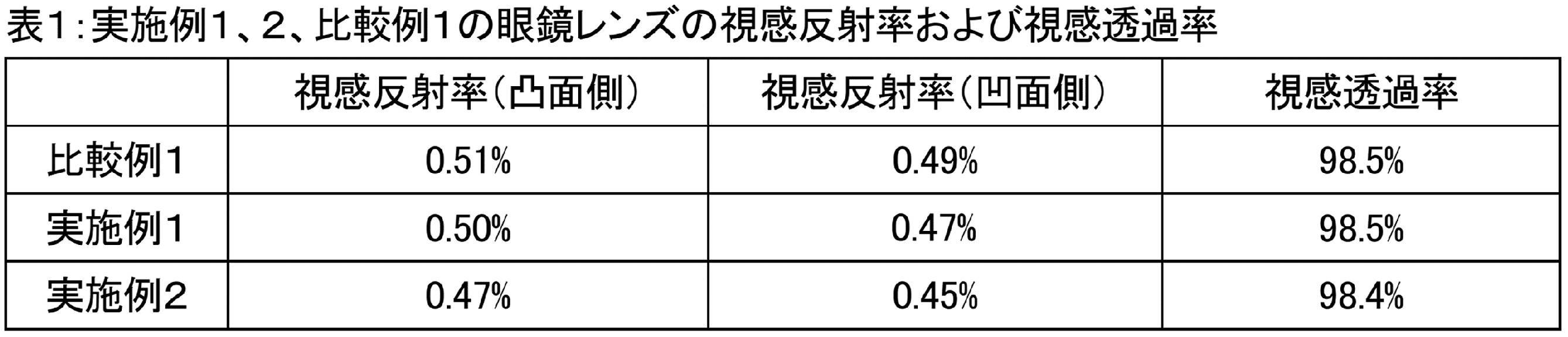
実施例1、2、比較例1の各眼鏡レンズについて、JIS Z 2801:2012にしたがって抗菌性試験を行った。
具体的には、各眼鏡レンズから、抗菌性の初期評価、耐水性評価および耐光性評価のために、試料片を3つ切り出す。試料片のサイズは50mm×50mmとする。
初期評価は、以下の方法によって実施する。
各眼鏡レンズから切り出した試験片を、上記の各種の層を積層した側の表面を上方に向けて滅菌済みシャーレに入れる。その後、1.0×10⁵個~4.0×10⁵個の試験菌(黄色ブドウ球菌または大腸菌)を含む菌液0.4mlを試料の上記表面の中央部に滴下し、40mm×40mmのサイズに切断したポリエチレンフィルムで被覆する。このシャーレを相対湿度90%以上の環境に24時間置いた後の1cm2あたりの生菌数を測定する。
耐水性評価は、以下の方法によって実施する。
各眼鏡レンズから切り出した試験片に対して、SIAA(抗菌製品技術協議会)の持続性試験法(2018年度版)の耐水性試験の章に記載の区分1の耐水性試験を実施した後、上記と同様の処理を行い、生菌数を測定する。
耐光性評価は、以下の方法によって実施する。
各眼鏡レンズから切り出した試験片に対して、SIAA(抗菌製品技術協議会)の持続性試験法(2018年度版)の耐水性試験の章に記載の区分1の耐光性試験を実施した後、上記と同様の処理を行い、生菌数を測定する。 [Antibacterial test]
The antibacterial test was performed on each of the spectacle lenses of Examples 1 and 2 and Comparative Example 1 according to JIS Z 2801: 2012.
Specifically, three sample pieces are cut out from each spectacle lens for initial evaluation of antibacterial property, water resistance evaluation, and light resistance evaluation. The size of the sample piece is 50 mm × 50 mm.
The initial evaluation is carried out by the following method.
The test piece cut out from each spectacle lens is placed in a sterilized petri dish with the surface on the side where the above-mentioned various layers are laminated face upward. Then, 0.4 ml of a bacterial solution containing 1.0 × 10 5 to 4.0 × 10 5 test bacteria (Staphylococcus aureus or Escherichia coli) was dropped onto the center of the surface of the sample to obtain a size of 40 mm × 40 mm. Cover with polyethylene film cut to size. The viable cell count per 1 cm 2 after placing this petri dish in an environment with a relative humidity of 90% or more for 24 hours is measured.
The water resistance evaluation is carried out by the following method.
After performing the water resistance test of
The light resistance evaluation is carried out by the following method.
After performing the light resistance test of
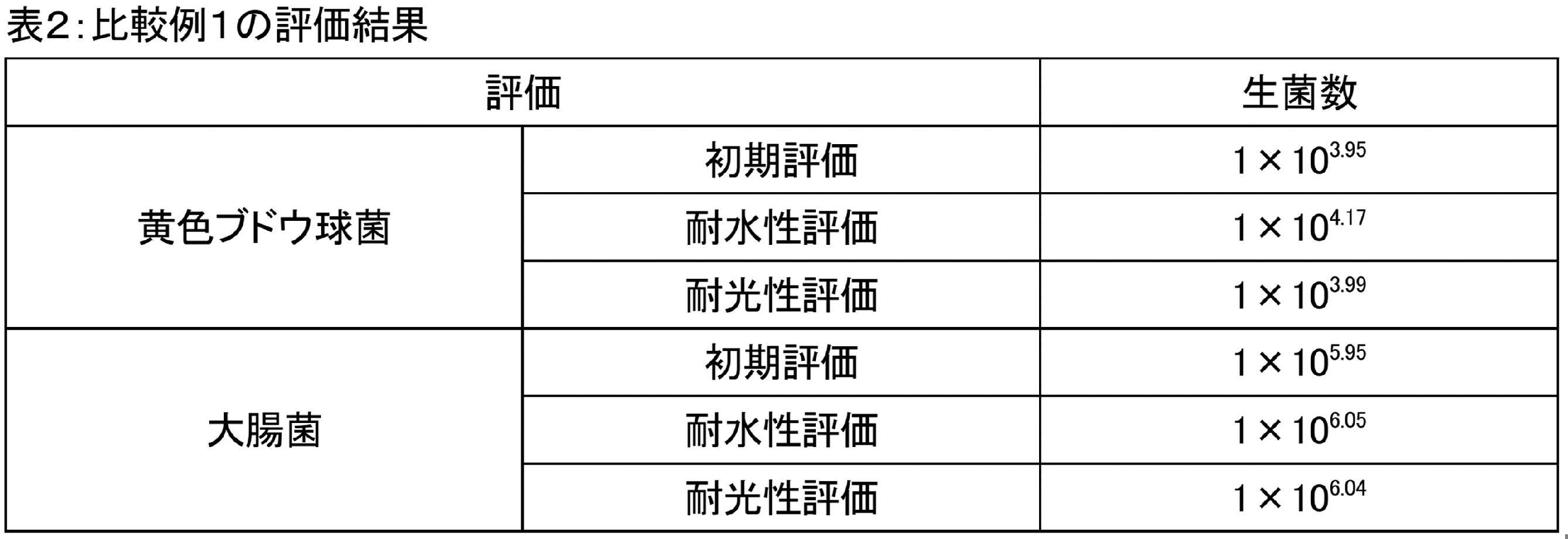
実施例2について、上記の各種評価で測定された生菌数から以下の式によって抗菌活性値を求めた。 For Example 1, the antibacterial activity value was determined by the following formula from the viable cell counts measured in the above various evaluations.
For Example 2, the antibacterial activity value was determined by the following formula from the viable cell counts measured in the above various evaluations.
Ut:比較例1の試料片での生菌数の対数値
At:実施例1または実施例2の試料片での生菌数の対数値 Antibacterial activity value = Ut-At
Ut: Log of viable cell count in the sample piece of Comparative Example 1 At: Logistic value of viable cell count in the sample piece of Example 1 or Example 2.


Claims (8)
- 眼鏡レンズの製造方法であって、
前記眼鏡レンズは、金属含有層を有し、
前記金属含有層を、金属粒子を担体に担持した蒸着源に電子ビームを照射することを含む電子ビーム蒸着によって形成することを含む、眼鏡レンズの製造方法。 It is a manufacturing method of spectacle lenses.
The spectacle lens has a metal-containing layer and has a metal-containing layer.
A method for manufacturing a spectacle lens, comprising forming the metal-containing layer by electron beam vapor deposition, which comprises irradiating a vapor deposition source on which metal particles are supported on a carrier with an electron beam. - 前記金属粒子は、銀粒子を含む、請求項1に記載の眼鏡レンズの製造方法。 The method for manufacturing a spectacle lens according to claim 1, wherein the metal particles include silver particles.
- 前記金属粒子は、白金粒子、金粒子、パラジウム粒子、水銀粒子、カドミウム粒子、コバルト粒子、ニッケル粒子、銅粒子、亜鉛粒子およびチタン粒子からなる群から選ばれる金属粒子の1種以上を更に含む、請求項2に記載の眼鏡レンズの製造方法。 The metal particles further include one or more of metal particles selected from the group consisting of platinum particles, gold particles, palladium particles, mercury particles, cadmium particles, cobalt particles, nickel particles, copper particles, zinc particles and titanium particles. The method for manufacturing a spectacle lens according to claim 2.
- 前記金属粒子を含む溶液を前記担体に含浸させた後に乾燥処理を行うことによって、前記担体に前記金属粒子を担持させることを更に含む、請求項1~3のいずれか1項に記載の眼鏡レンズの製造方法。 The spectacle lens according to any one of claims 1 to 3, further comprising supporting the metal particles on the carrier by impregnating the carrier with a solution containing the metal particles and then performing a drying treatment. Manufacturing method.
- 前記担体は多孔質体である、請求項1~4のいずれか1項に記載の眼鏡レンズの製造方法。 The method for manufacturing a spectacle lens according to any one of claims 1 to 4, wherein the carrier is a porous body.
- 前記多孔質体は焼結フィルタである、請求項5に記載の眼鏡レンズの製造方法。 The method for manufacturing a spectacle lens according to claim 5, wherein the porous body is a sintered filter.
- 前記金属含有層は、金属含有無機層である、請求項1~6のいずれか1項に記載の眼鏡レンズの製造方法。 The method for manufacturing a spectacle lens according to any one of claims 1 to 6, wherein the metal-containing layer is a metal-containing inorganic layer.
- 前記金属含有層の膜厚は、5nm以下である、請求項1~7のいずれか1項に記載の眼鏡レンズの製造方法。 The method for manufacturing a spectacle lens according to any one of claims 1 to 7, wherein the thickness of the metal-containing layer is 5 nm or less.
Priority Applications (3)
| Application Number | Priority Date | Filing Date | Title |
|---|---|---|---|
| EP21889303.0A EP4242733A1 (en) | 2020-11-09 | 2021-11-09 | Method for producing eyeglass lens |
| US18/035,383 US20230407456A1 (en) | 2020-11-09 | 2021-11-09 | Method for producing eyeglass lens |
| CN202180075414.9A CN116438482A (en) | 2020-11-09 | 2021-11-09 | Method for manufacturing spectacle lens |
Applications Claiming Priority (4)
| Application Number | Priority Date | Filing Date | Title |
|---|---|---|---|
| JP2020-186826 | 2020-11-09 | ||
| JP2020186826 | 2020-11-09 | ||
| JP2021084592A JP7203147B2 (en) | 2020-11-09 | 2021-05-19 | Spectacle lens manufacturing method |
| JP2021-084592 | 2021-05-19 |
Publications (1)
| Publication Number | Publication Date |
|---|---|
| WO2022097752A1 true WO2022097752A1 (en) | 2022-05-12 |
Family
ID=81458303
Family Applications (1)
| Application Number | Title | Priority Date | Filing Date |
|---|---|---|---|
| PCT/JP2021/041074 WO2022097752A1 (en) | 2020-11-09 | 2021-11-09 | Method for producing eyeglass lens |
Country Status (5)
| Country | Link |
|---|---|
| US (1) | US20230407456A1 (en) |
| EP (1) | EP4242733A1 (en) |
| JP (1) | JP2023009170A (en) |
| CN (1) | CN116438482A (en) |
| WO (1) | WO2022097752A1 (en) |
Cited By (1)
| Publication number | Priority date | Publication date | Assignee | Title |
|---|---|---|---|---|
| WO2023189159A1 (en) * | 2022-03-31 | 2023-10-05 | ホヤ レンズ タイランド リミテッド | Method for producing spectacle lens |
Citations (8)
| Publication number | Priority date | Publication date | Assignee | Title |
|---|---|---|---|---|
| JPS59132940A (en) * | 1982-12-30 | 1984-07-31 | ジヨフリ−・アレン・オ−ジン | Production of metal-zeolite catalyst |
| JPH03126865A (en) * | 1989-10-13 | 1991-05-30 | Toshiba Corp | Electron beam evaporating device |
| JPH09327622A (en) | 1996-06-12 | 1997-12-22 | Sumitomo Chem Co Ltd | Anti-bacterial surface coating agent and synthetic resin molded body |
| JP2001207260A (en) * | 2000-01-27 | 2001-07-31 | Canon Inc | Film deposition method and film deposition system |
| JP2008107836A (en) * | 2002-03-18 | 2008-05-08 | Hoya Corp | Process for producing optical member and thin film |
| JP2018012877A (en) * | 2016-07-22 | 2018-01-25 | 稀産金属株式会社 | Antibacterial material, antibacterial thin film and method for producing antibacterial thin film |
| JP2020106751A (en) * | 2018-12-28 | 2020-07-09 | ホヤ レンズ タイランド リミテッドHOYA Lens Thailand Ltd | Spectacle lens |
| JP2020142494A (en) * | 2019-03-07 | 2020-09-10 | 伊藤光学工業株式会社 | Antibacterial transparent laminate and producing method thereof |
-
2021
- 2021-11-09 EP EP21889303.0A patent/EP4242733A1/en active Pending
- 2021-11-09 WO PCT/JP2021/041074 patent/WO2022097752A1/en active Application Filing
- 2021-11-09 CN CN202180075414.9A patent/CN116438482A/en active Pending
- 2021-11-09 US US18/035,383 patent/US20230407456A1/en active Pending
-
2022
- 2022-11-11 JP JP2022180667A patent/JP2023009170A/en active Pending
Patent Citations (8)
| Publication number | Priority date | Publication date | Assignee | Title |
|---|---|---|---|---|
| JPS59132940A (en) * | 1982-12-30 | 1984-07-31 | ジヨフリ−・アレン・オ−ジン | Production of metal-zeolite catalyst |
| JPH03126865A (en) * | 1989-10-13 | 1991-05-30 | Toshiba Corp | Electron beam evaporating device |
| JPH09327622A (en) | 1996-06-12 | 1997-12-22 | Sumitomo Chem Co Ltd | Anti-bacterial surface coating agent and synthetic resin molded body |
| JP2001207260A (en) * | 2000-01-27 | 2001-07-31 | Canon Inc | Film deposition method and film deposition system |
| JP2008107836A (en) * | 2002-03-18 | 2008-05-08 | Hoya Corp | Process for producing optical member and thin film |
| JP2018012877A (en) * | 2016-07-22 | 2018-01-25 | 稀産金属株式会社 | Antibacterial material, antibacterial thin film and method for producing antibacterial thin film |
| JP2020106751A (en) * | 2018-12-28 | 2020-07-09 | ホヤ レンズ タイランド リミテッドHOYA Lens Thailand Ltd | Spectacle lens |
| JP2020142494A (en) * | 2019-03-07 | 2020-09-10 | 伊藤光学工業株式会社 | Antibacterial transparent laminate and producing method thereof |
Cited By (1)
| Publication number | Priority date | Publication date | Assignee | Title |
|---|---|---|---|---|
| WO2023189159A1 (en) * | 2022-03-31 | 2023-10-05 | ホヤ レンズ タイランド リミテッド | Method for producing spectacle lens |
Also Published As
| Publication number | Publication date |
|---|---|
| CN116438482A (en) | 2023-07-14 |
| US20230407456A1 (en) | 2023-12-21 |
| JP2023009170A (en) | 2023-01-19 |
| EP4242733A1 (en) | 2023-09-13 |
Similar Documents
| Publication | Publication Date | Title |
|---|---|---|
| EP2286985B1 (en) | Method of producing a plastic lens having an antistatic coating | |
| WO2014069250A1 (en) | Optical component, method for producing optical component, and method for quantitatively determining ghost light | |
| JP2010102157A (en) | Optical article and method for manufacturing the same | |
| WO2014208412A1 (en) | Optical component | |
| US20220214562A1 (en) | Spectacle lens and method for manufacturing spectacle lens | |
| WO2022097752A1 (en) | Method for producing eyeglass lens | |
| WO2022097751A1 (en) | Spectacle lens and eyeglasses | |
| JP2010231174A (en) | Optical article and method for producing the same | |
| WO2022209094A1 (en) | Eyeglass lens, manufacturing method for eyeglass lens, and eyeglasses | |
| JP7203147B2 (en) | Spectacle lens manufacturing method | |
| JP7242753B2 (en) | spectacle lenses and spectacles | |
| WO2023189159A1 (en) | Method for producing spectacle lens | |
| WO2022209093A1 (en) | Method for producing spectacle lens | |
| JP2010072636A (en) | Optical article and method for manufacturing the same | |
| JP6461313B2 (en) | GLASSES LENS, MANUFACTURING METHOD THEREOF, AND GLASSES | |
| JP2011017949A (en) | Method for producing optical article, and optical article produced by the method | |
| JP2010072635A (en) | Optical article and method for manufacturing the same | |
| WO2022210114A1 (en) | Eyeglass plastic lens | |
| CN117120913A (en) | Spectacle lens and spectacles |
Legal Events
| Date | Code | Title | Description |
|---|---|---|---|
| 121 | Ep: the epo has been informed by wipo that ep was designated in this application |
Ref document number: 21889303 Country of ref document: EP Kind code of ref document: A1 |
|
| WWE | Wipo information: entry into national phase |
Ref document number: 18035383 Country of ref document: US |
|
| WWE | Wipo information: entry into national phase |
Ref document number: 2021889303 Country of ref document: EP |
|
| NENP | Non-entry into the national phase |
Ref country code: DE |
|
| ENP | Entry into the national phase |
Ref document number: 2021889303 Country of ref document: EP Effective date: 20230609 |