WO2022097648A1 - 操作装置 - Google Patents
操作装置 Download PDFInfo
- Publication number
- WO2022097648A1 WO2022097648A1 PCT/JP2021/040420 JP2021040420W WO2022097648A1 WO 2022097648 A1 WO2022097648 A1 WO 2022097648A1 JP 2021040420 W JP2021040420 W JP 2021040420W WO 2022097648 A1 WO2022097648 A1 WO 2022097648A1
- Authority
- WO
- WIPO (PCT)
- Prior art keywords
- lever
- operating device
- actuator
- metal plate
- frame
- Prior art date
- Legal status (The legal status is an assumption and is not a legal conclusion. Google has not performed a legal analysis and makes no representation as to the accuracy of the status listed.)
- Ceased
Links
Images



Classifications
-
- G—PHYSICS
- G05—CONTROLLING; REGULATING
- G05G—CONTROL DEVICES OR SYSTEMS INSOFAR AS CHARACTERISED BY MECHANICAL FEATURES ONLY
- G05G9/00—Manually-actuated control mechanisms provided with one single controlling member co-operating with two or more controlled members, e.g. selectively, simultaneously
- G05G9/02—Manually-actuated control mechanisms provided with one single controlling member co-operating with two or more controlled members, e.g. selectively, simultaneously the controlling member being movable in different independent ways, movement in each individual way actuating one controlled member only
- G05G9/04—Manually-actuated control mechanisms provided with one single controlling member co-operating with two or more controlled members, e.g. selectively, simultaneously the controlling member being movable in different independent ways, movement in each individual way actuating one controlled member only in which movement in two or more ways can occur simultaneously
- G05G9/047—Manually-actuated control mechanisms provided with one single controlling member co-operating with two or more controlled members, e.g. selectively, simultaneously the controlling member being movable in different independent ways, movement in each individual way actuating one controlled member only in which movement in two or more ways can occur simultaneously the controlling member being movable by hand about orthogonal axes, e.g. joysticks
-
- G—PHYSICS
- G05—CONTROLLING; REGULATING
- G05G—CONTROL DEVICES OR SYSTEMS INSOFAR AS CHARACTERISED BY MECHANICAL FEATURES ONLY
- G05G9/00—Manually-actuated control mechanisms provided with one single controlling member co-operating with two or more controlled members, e.g. selectively, simultaneously
- G05G9/02—Manually-actuated control mechanisms provided with one single controlling member co-operating with two or more controlled members, e.g. selectively, simultaneously the controlling member being movable in different independent ways, movement in each individual way actuating one controlled member only
- G05G9/04—Manually-actuated control mechanisms provided with one single controlling member co-operating with two or more controlled members, e.g. selectively, simultaneously the controlling member being movable in different independent ways, movement in each individual way actuating one controlled member only in which movement in two or more ways can occur simultaneously
- G05G9/047—Manually-actuated control mechanisms provided with one single controlling member co-operating with two or more controlled members, e.g. selectively, simultaneously the controlling member being movable in different independent ways, movement in each individual way actuating one controlled member only in which movement in two or more ways can occur simultaneously the controlling member being movable by hand about orthogonal axes, e.g. joysticks
- G05G2009/04703—Mounting of controlling member
- G05G2009/04714—Mounting of controlling member with orthogonal axes
- G05G2009/04718—Mounting of controlling member with orthogonal axes with cardan or gimbal type joint
-
- G—PHYSICS
- G05—CONTROLLING; REGULATING
- G05G—CONTROL DEVICES OR SYSTEMS INSOFAR AS CHARACTERISED BY MECHANICAL FEATURES ONLY
- G05G9/00—Manually-actuated control mechanisms provided with one single controlling member co-operating with two or more controlled members, e.g. selectively, simultaneously
- G05G9/02—Manually-actuated control mechanisms provided with one single controlling member co-operating with two or more controlled members, e.g. selectively, simultaneously the controlling member being movable in different independent ways, movement in each individual way actuating one controlled member only
- G05G9/04—Manually-actuated control mechanisms provided with one single controlling member co-operating with two or more controlled members, e.g. selectively, simultaneously the controlling member being movable in different independent ways, movement in each individual way actuating one controlled member only in which movement in two or more ways can occur simultaneously
- G05G9/047—Manually-actuated control mechanisms provided with one single controlling member co-operating with two or more controlled members, e.g. selectively, simultaneously the controlling member being movable in different independent ways, movement in each individual way actuating one controlled member only in which movement in two or more ways can occur simultaneously the controlling member being movable by hand about orthogonal axes, e.g. joysticks
- G05G2009/04766—Manually-actuated control mechanisms provided with one single controlling member co-operating with two or more controlled members, e.g. selectively, simultaneously the controlling member being movable in different independent ways, movement in each individual way actuating one controlled member only in which movement in two or more ways can occur simultaneously the controlling member being movable by hand about orthogonal axes, e.g. joysticks providing feel, e.g. indexing means, means to create counterforce
-
- G—PHYSICS
- G05—CONTROLLING; REGULATING
- G05G—CONTROL DEVICES OR SYSTEMS INSOFAR AS CHARACTERISED BY MECHANICAL FEATURES ONLY
- G05G9/00—Manually-actuated control mechanisms provided with one single controlling member co-operating with two or more controlled members, e.g. selectively, simultaneously
- G05G9/02—Manually-actuated control mechanisms provided with one single controlling member co-operating with two or more controlled members, e.g. selectively, simultaneously the controlling member being movable in different independent ways, movement in each individual way actuating one controlled member only
- G05G9/04—Manually-actuated control mechanisms provided with one single controlling member co-operating with two or more controlled members, e.g. selectively, simultaneously the controlling member being movable in different independent ways, movement in each individual way actuating one controlled member only in which movement in two or more ways can occur simultaneously
- G05G9/047—Manually-actuated control mechanisms provided with one single controlling member co-operating with two or more controlled members, e.g. selectively, simultaneously the controlling member being movable in different independent ways, movement in each individual way actuating one controlled member only in which movement in two or more ways can occur simultaneously the controlling member being movable by hand about orthogonal axes, e.g. joysticks
- G05G2009/04777—Manually-actuated control mechanisms provided with one single controlling member co-operating with two or more controlled members, e.g. selectively, simultaneously the controlling member being movable in different independent ways, movement in each individual way actuating one controlled member only in which movement in two or more ways can occur simultaneously the controlling member being movable by hand about orthogonal axes, e.g. joysticks with additional push or pull action on the handle
Definitions
- the present invention relates to an operating device.
- Patent Document 1 discloses a technique of providing an annular groove portion for preventing the outflow of a lubricant on the upper surface of a cover member on which a drive portion of an operating body slides in a multi-directional input device. Further, in Patent Document 1 below, it is shown that a convex portion is provided on the back surface of the cover member. Such a convex portion has effects such as increasing the rigidity of the cover member and stably fixing the back surface of the cover member to the installation target surface.
- the operating device is provided with a lever that can be tilted and connected to the lower portion of the lever, a drive body that gives a returning force to the lever when the lever is tilted, and a lower end of the drive body. It is provided facing the contact portion and has a metal plate having an upper surface that slides while the contact portion is in contact with the lever when the lever is tilted. The metal plate has a contact portion that slides on the upper surface.
- a groove-shaped restraining portion for suppressing the outflow of grease is provided on the outer side of the region to be formed, and a convex portion formed by forming the restraining portion is provided on the back surface opposite to the upper surface.
- a convex portion on the back surface of the metal plate can be easily formed.
- External perspective view of the operating device External perspective view of the operating device (with the case removed) according to the embodiment.
- Sectional drawing of the operation apparatus which concerns on one Embodiment External perspective view showing the configuration of the upper surface side of the frame according to one embodiment.
- External perspective view showing the configuration of the back surface side of the frame according to one embodiment.
- Cross-sectional view of the frame according to an embodiment in a YZ plane Partially enlarged cross-sectional view of the operating device according to the embodiment
- FIG. 1 is an external perspective view of the operating device 100 according to the embodiment.
- the Z-axis direction in the figure is the vertical direction
- the X-axis direction in the figure is the front-back direction
- the Y-axis direction in the figure is the left-right direction.
- the operation device 100 shown in FIG. 1 is used for a controller or the like of a game machine or the like.
- the operating device 100 has a columnar, tiltable lever 120 extending upward from the opening 102A of the case 102.
- the operating device 100 can be tilted not only in the front-rear direction (arrows D1 and D2 in the figure) and left-right direction (arrows D3 and D4 in the figure) by the lever 120, but also in all directions between these directions. be.
- the operation device 100 can output an operation signal corresponding to the tilt operation (tilt direction and tilt angle) of the lever 120 to the outside via the FPC (Flexible Printed Circuits) 112.
- FPC Flexible Printed Circuits
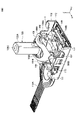
- FIG. 2 is an external perspective view of the operating device 100 (state in which the case 102 is removed) according to the embodiment.
- FIG. 3 is an exploded perspective view of the operating device 100 according to the embodiment.
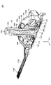
- FIG. 4 is a cross-sectional view of the operating device 100 according to the embodiment.
- the operating device 100 includes a case 102, a lever 120, an actuator 104, a holder 105, an actuator 106, an actuator 103, a spring 108, a holder 107, a pressing member 109, a frame 110, an FPC 112, and a metal.
- a sheet 113 is provided.
- the case 102 has an upwardly convex dome shape.
- each component (lever 120, actuator 103, 104, 106, and holder 105, 107) is incorporated in the internal space.
- an opening 102A having a circular shape in a plan view from above is formed at the top of a portion having a dome shape.
- the lever 120 is a member that is tilted by the operator.
- the lever 120 has a lever portion 120A and a base portion 120B.
- the lever portion 120A is a substantially columnar portion extending upward from the opening 102A of the case 102, and is a portion that is tilted by the operator.
- the base portion 120B is a substantially columnar portion that supports the lower end portion of the lever 120 inside the case 102 and rotates with the tilting operation of the lever portion 120A.
- the actuator 104 has a dome shape that is convexly curved upward, and has an elongated hole-shaped opening 104A that extends in the left-right direction (Y-axis direction in the figure) along the curved shape.
- the actuator 104 has a rotation shaft 104B protruding outward at each of both ends in the left-right direction, and the rotation shaft 104B is supported by the case 102 so that the rotation shaft 104B is the center of rotation. , Is rotatably provided in the front-back direction (X-axis direction in the figure).
- the actuator 106 is provided so as to be overlapped on the upper side of the actuator 104.
- the actuator 106 has an upwardly curved shape, and has an elongated hole-shaped opening 106A extending in the front-rear direction (X-axis direction in the drawing) along the curved shape.
- the actuator 106 has a rotation shaft 106B protruding outward at each of both ends in the front-rear direction, and the rotation shaft 106B is supported by the case 102 so that the rotation shaft 106B is the center of rotation. , Is rotatably provided in the left-right direction (Y-axis direction in the figure).
- the holder 105 holds the slider 105A on the lower side.
- the holder 105 has a longitudinal shape extending in the sliding direction (X-axis direction) of the slider 105A.
- the holder 105 is slidably provided in the sliding direction (X-axis direction) of the slider 105A.
- a protrusion 105B is provided at the center of the side surface of the holder 105.
- the holder 107 holds the slider 107A on the lower side.
- the holder 107 has a longitudinal shape extending in the sliding direction (Y-axis direction) of the slider 107A.
- the holder 107 is slidably provided in the sliding direction (Y-axis direction) of the slider 107A.
- a protrusion 107B is provided at the center of the side surface of the holder 107.
- the actuator 104 and the actuator 106 overlap each other so that the opening 104A and the opening 106A intersect each other.
- the actuator 104 and the actuator 106 pass through the lever portion 120A of the lever 120 from the opening 104A and the opening 106A in a state of being overlapped with each other, engage the actuator 104 with the base portion 120B of the lever 120, and are incorporated in the case 102. Is done.
- the actuator 104 has an engaging portion 104C protruding downward from the rotating shaft 104B on the positive side of the Y axis.
- the engaging portion 104C engages with a protrusion 105B provided at the center of the side surface of the holder 105 slidably provided on the FPC 112 in the front-rear direction (X-axis direction).
- the actuator 104 rotates in the front-rear direction together with the base 120B of the lever 120 when the lever 120 tilts in the front-rear direction (X-axis direction), and slides the holder 105 in the front-rear direction.
- the actuator 106 has an engaging portion 106C protruding downward from the rotating shaft 106B on the positive side of the X axis.
- the engaging portion 106C engages with a protrusion 107B provided at the center of the side surface of the holder 107 slidably provided on the FPC 112 in the left-right direction (Y-axis direction).
- the actuator 106 rotates in the left-right direction together with the base 120B of the lever 120 when the lever 120 tilts in the left-right direction (Y-axis direction), and slides the holder 107 in the left-right direction.
- the actuator 103 is an example of a "driving body". It has a shaft portion 103A and a bottom plate portion 103B.
- the shaft portion 103A is a round bar-shaped portion inserted and arranged in the through hole 120C of the lever 120.
- the bottom plate portion 103B is a disk-shaped portion integrally provided at the lower end portion of the shaft portion 103A.
- the actuator 103 is provided connected to the lower part of the lever 120, and when the lever 120 is tilted, the urging force from the spring 108 is used to give a returning force to the lever 120.
- the spring 108 is incorporated into the opening (see FIG. 4) on the bottom surface side (Z-axis negative side) of the lever 120 together with the actuator 103 in a state where the shaft portion 103A of the actuator 103 is inserted.
- the spring 108 urges the lever 120 upward and urges the bottom plate portion 103B of the actuator 103 downward.
- the spring 108 presses the bottom plate portion 103B of the actuator 103 against the upper surface and the central portion of the frame 110 to bring the bottom plate portion 103B into a horizontal state. This returns the lever 120 to the neutral state.
- the frame 110 is an example of a "metal plate", and is a metal and flat plate-shaped member that closes an opening on the bottom surface side of the case 102.
- the frame 110 is formed by performing various processing methods (for example, punching processing, bending processing, etc.) on a metal plate.
- the frame 110 is provided with a pair of claw portions 111 on each of the front side (X-axis positive side) edge portion and the rear side (X-axis negative side) edge portion. That is, the claw portion 111 is provided at each of the substantially four corner portions of the frame 110 having a rectangular shape by bending or the like.
- the frame 110 is fixed to the case 102 by engaging each claw portion 111 with the edge portion (generally each of the four corner portions) of the case 102. As a result, the frame 110 functions as a fixed frame for fixing the operating device 100.
- FPC112 is an example of a "board" and is a flexible film-shaped wiring member.
- the FPC 112 has an extending portion 112A extending from the upper surface of the frame 110 to the side of the frame 110 (in the negative direction of the Y axis in the drawing), and the connecting portion 112B provided at the tip of the extending portion 112A. Is connected to the outside.
- the FPC 112 transmits an operation signal corresponding to the operation of the lever 120 (tilting operation and pressing operation) to the outside.
- the FPC 112 covers both surfaces of a strip-shaped conductor wiring (for example, copper foil, etc.) with a film-like material having flexibility and insulation (for example, polyimide resin, polyethylene terephthalate (PET), etc.). Consists of.
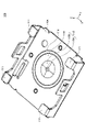
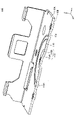
- FIG. 5 is an external perspective view showing the configuration of the frame 110 according to the embodiment on the upper surface 110A side.
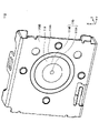
- FIG. 6 is an external perspective view showing a configuration on the back surface 110B side of the frame 110 according to the embodiment.
- FIG. 7 is a cross-sectional view of the frame 110 according to the embodiment in a YZ plane.
- FIG. 8 is a partially enlarged cross-sectional view of the operating device 100 according to the embodiment.
- a convex portion 115 is provided substantially in the center of the frame 110.
- the convex portion 115 is a substantially truncated cone-shaped portion protruding upward from the upper surface 110A of the frame 110.
- the convex portion 115 is formed by applying pressure to the frame 110 from the back surface 110B side by press working and deforming the frame 110.
- the convex portion 115 has a top portion 115A provided at the center thereof and an inclined surface 115B inclined so that the altitude gradually increases toward the top portion 115A.
- the convex portion 115 is formed on the lower side of the bottom plate portion 103B of the actuator 103 and on the central axis AX of the actuator 103 in the frame 110.
- a hollow portion 103C having an upwardly recessed shape is formed on the bottom surface of the bottom plate portion 103B of the actuator 103.
- the cavity 103C has a circular shape centered on the central axis AX in a plan view. As shown in FIG. 8, the cavity 103C contacts the contact portion 103Ba of the actuator 103 with the upper surface 110A of the frame 110 while avoiding contact of the convex portion 115 of the frame 110 with the bottom surface of the bottom plate portion 103B of the actuator 103. It is provided to enable it.
- annular contact portion 103Ba surrounding the cavity 103C is formed. As shown in FIG. 8, when the actuator 103 is in the neutral state, the contact portion 103Ba abuts on the annular flat surface portion 116 on the upper surface 110A of the frame 110 over the entire annular shape. Then, the contact portion 103Ba is pressed against the annular flat surface portion 116 by the urging force from the spring 108 to stabilize the neutral state of the actuator 103.
- a deterrent portion 114 having a downwardly recessed shape (that is, a groove shape) is formed on the upper surface 110A of the frame 110.
- the restraining portion 114 has an annular shape centered on the convex portion 115 in a plan view. Since the restraint portion 114 is formed on the upper surface 110A of the frame 110, an annular flat surface portion 116 is formed between the restraint portion 114 and the convex portion 115.
- the convex portion 115 and the annular flat surface portion 116 are regions in which the contact portion 103Ba of the actuator 103 slides when the actuator 103 is tilted.
- the restraining portion 114 has an annular shape surrounding the convex portion 115 and the annular flat surface portion 116.
- the diameter of the restraint portion 114 is larger than the diameter of the bottom plate portion 103B of the actuator 103, so that the region (that is, the convex portion 115 and the convex portion 115) on which the contact portion 103Ba of the actuator 103 slides. It surrounds the annular flat surface portion 116).
- the surfaces of the convex portion 115 and the annular flat surface portion 116 are coated with grease for lubricating the sliding of the contact portion 103Ba.
- the restraining portion 114 can store the grease scraped out by the contact portion 103Ba in the direction opposite to the tilting direction of the actuator 103.
- the restraining unit 114 can prevent the grease scraped out in the direction opposite to the tilting direction of the actuator 103 from flowing out of the restraining unit 114.
- the contact portion 103Ba of the actuator moves in the negative direction of the X-axis.
- the restraining unit 114 is formed by applying pressure to the frame 110 from the upper surface 110A side by press working and deforming the frame 110.
- the restraining portion 114 is convex downward and at the same position as the restraining portion 114 in a plan view.
- a convex portion 114A having the same shape (that is, an annular shape) is formed.
- the operation device 100 By having the convex portion 114A on the back surface 110B of the frame 110, the operation device 100 according to the embodiment can increase the rigidity of the frame 110 while making the frame 110 thinner. As a result, the operating device 100 according to the embodiment can suppress the deformation of the frame 110 even when the pressing operation is performed by the lever 120, for example.
- the frame 110 since the frame 110 has the convex portion 114A, for example, the back surface 110B of the frame 110 is placed on the installation target surface (for example, the wall surface inside the housing of the game controller).
- the installation target surface for example, the wall surface inside the housing of the game controller.
- the operating device 100 can form the convex portion 114A on the back surface 110B of the frame 110 by forming the restraining portion 114 on the upper surface 110A of the frame 110. Therefore, according to the operating device 100 according to the embodiment, in the operating device having a restraining portion for suppressing the outflow of grease on the upper surface of the metal plate, the convex portion on the back surface of the metal plate can be easily formed.
- the restraining portion 114 and the convex portion 114A have an annular shape in a plan view, grease is applied regardless of the tilting direction of the actuator 103 in any direction of 360 degrees. Can be prevented from flowing out of the restraining portion 114, and the back surface 110B of the frame 110 can be more stably fixed to the installation target surface.
- an FPC 112 (an example of a "flexible substrate") is provided on the upper surface 110A of the frame 110.
- the FPC 112 has an opening edge portion 112C outside the region where the contact portion 103Ba of the actuator 103 slides (that is, the convex portion 115 and the annular flat portion 116).
- the operating device 100 according to the embodiment slips the grease scraped out in the direction opposite to the tilting direction of the actuator 103 from the opening edge 112C of the FPC 112 between the FPC 112 and the upper surface 110A of the frame 110. Can be made. Therefore, the operating device 100 according to the embodiment can prevent the grease scraped out in the direction opposite to the tilting direction of the actuator 103 from flowing out to the upper surface of the FPC 112.
- the FPC 112 is fixed to the frame 110 by any fixing means outside the region where the contact portion 103Ba of the actuator 103 slides (that is, the convex portion 115 and the annular flat portion 116).
- the operating device 100 can partially raise the opening edge 112C of the FPC 112 upward, so that the grease scraped out in the direction opposite to the tilting direction of the actuator 103 can be removed. , It is possible to easily slip between the FPC 112 and the upper surface 110A of the frame 110.
- the frame 110 is formed on the outer peripheral edge portion of the frame 110 by bending, and a plurality of claw portions 111 that engage with the edge portion of the case 102 of the operation device 100 are provided.
- the restraining portion 114 is formed between two adjacent claw portions 111 in a plan view (see FIG. 5). That is, in FIG. 5, a pair of claw portions 111 that are bent so as to face each other in the X-axis direction are tentatively extended in the X-axis direction so as to be connected to each other at each of the Y-axis positive side end portion and the Y-axis negative side end portion.
- the operating device 100 is formed at a position where the restraining portion 114 and the convex portion 114A are separated from the region susceptible to the bending process when the plurality of claw portions 111 are formed by the bending process. Therefore, it is possible to suppress the occurrence of strain due to the bending process, that is, the restraining portion 114 and the convex portion 114A can be formed with high accuracy.
- the shapes of the restraining portion 114 and the convex portion 114A are not limited to the annular shape.
- the shape of the restraining portion 114 and the convex portion 114A may be a polygonal (for example, quadrangular) frame shape.
- the shape of the restraining portion 114 and the convex portion 114A may be a shape in which a part of the annular shape is interrupted, a shape in which a part of the polygonal frame shape is interrupted, or the like.
- it is preferable that the restraining portion 114 and the convex portion 114A are provided at least in a direction opposite to the tilting direction of the actuator 103. For example, when the actuator 103 can be tilted only in the X-axis direction, the restraining portion 114 and the convex portion 114A may be provided only in the X-axis direction and not in the Y-axis direction.
Landscapes
- Physics & Mathematics (AREA)
- General Physics & Mathematics (AREA)
- Engineering & Computer Science (AREA)
- Automation & Control Theory (AREA)
- Switches With Compound Operations (AREA)
- Position Input By Displaying (AREA)
Abstract
Description
図1は、一実施形態に係る操作装置100の外観斜視図である。なお、以降の説明では、便宜上、図中Z軸方向を、上下方向とし、図中X軸方向を、前後方向とし、図中Y軸方向を、左右方向とする。
図2は、一実施形態に係る操作装置100(ケース102が取り外された状態)の外観斜視図である。図3は、一実施形態に係る操作装置100の分解斜視図である。図4は、一実施形態に係る操作装置100の断面図である。
図5は、一実施形態に係るフレーム110の上面110A側の構成を示す外観斜視図である。図6は、一実施形態に係るフレーム110の裏面110B側の構成を示す外観斜視図である。図7は、一実施形態に係るフレーム110のYZ平面による断面図である。図8は、一実施形態に係る操作装置100の一部拡大断面図である。
102 ケース
103 アクチュエータ(駆動体)
104 アクチュエータ
105 ホルダ
106 アクチュエータ
107 ホルダ
108 スプリング
109 押圧部材
110 フレーム(金属板)
111 爪部
112 FPC(フレキシブル基板)
112C 開口縁部
113 メタルシート
114 抑止部
114A 凸状部
115 凸部
116 環状平面部
120 レバー
Claims (7)
- 傾倒操作可能なレバーと、
前記レバーの下部に連結して設けられ、前記レバーが傾倒したときに、前記レバーに復帰力を与える駆動体と、
前記駆動体の下端に設けられた当接部と対向して設けられ、前記レバーが傾倒したときに、前記当接部が弾接しつつ摺動する上面を有する金属板と
を備え、
前記金属板は、
前記上面において、前記当接部が摺動する領域よりも外側に、グリスの流出を抑止する溝状の抑止部を有し、
前記上面とは反対側の裏面に、前記抑止部を形成することによって形成される凸状部を有する
ことを特徴とする操作装置。 - 前記抑止部および前記凸状部は、円環状を有する
ことを特徴とする請求項1に記載の操作装置。 - 前記レバーは、
さらに押圧操作が可能である
ことを特徴とする請求項1または2に記載の操作装置。 - 前記金属板の前記上面に重ねて設けられたフレキシブル基板をさらに備え、
前記フレキシブル基板は、
前記当接部が摺動する領域よりも外側に、開口縁部を有する
ことを特徴とする請求項1から3のいずれか一項に記載の操作装置。 - 前記フレキシブル基板は、
前記当接部が摺動する領域よりも外側で、前記金属板に固定される
ことを特徴とする請求項4に記載の操作装置。 - 前記金属板は、前記操作装置を固定する固定枠としての機能を有する
ことを特徴とする請求項1から5のいずれか一項に記載の操作装置。 - 前記金属板は、
当該金属板の外周縁部に、折り曲げ加工によって形成され、前記操作装置のケースに係合する複数の爪部を有し、
前記抑止部は、
平面視において、任意の隣り合う2つの前記爪部の間に形成されている
ことを特徴とする請求項1から6のいずれか一項に記載の操作装置。
Priority Applications (3)
| Application Number | Priority Date | Filing Date | Title |
|---|---|---|---|
| CN202180073632.9A CN116583811A (zh) | 2020-11-05 | 2021-11-02 | 操作装置 |
| JP2022560790A JPWO2022097648A1 (ja) | 2020-11-05 | 2021-11-02 | |
| US18/308,099 US20230266787A1 (en) | 2020-11-05 | 2023-04-27 | Operation device |
Applications Claiming Priority (2)
| Application Number | Priority Date | Filing Date | Title |
|---|---|---|---|
| JP2020-184845 | 2020-11-05 | ||
| JP2020184845 | 2020-11-05 |
Related Child Applications (1)
| Application Number | Title | Priority Date | Filing Date |
|---|---|---|---|
| US18/308,099 Continuation US20230266787A1 (en) | 2020-11-05 | 2023-04-27 | Operation device |
Publications (1)
| Publication Number | Publication Date |
|---|---|
| WO2022097648A1 true WO2022097648A1 (ja) | 2022-05-12 |
Family
ID=81457269
Family Applications (1)
| Application Number | Title | Priority Date | Filing Date |
|---|---|---|---|
| PCT/JP2021/040420 Ceased WO2022097648A1 (ja) | 2020-11-05 | 2021-11-02 | 操作装置 |
Country Status (4)
| Country | Link |
|---|---|
| US (1) | US20230266787A1 (ja) |
| JP (1) | JPWO2022097648A1 (ja) |
| CN (1) | CN116583811A (ja) |
| WO (1) | WO2022097648A1 (ja) |
Citations (2)
| Publication number | Priority date | Publication date | Assignee | Title |
|---|---|---|---|---|
| JPH11353109A (ja) * | 1998-04-10 | 1999-12-24 | Fujitsu Takamisawa Component Ltd | 入力装置 |
| WO2020105437A1 (ja) * | 2018-11-20 | 2020-05-28 | アルプスアルパイン株式会社 | 操作装置 |
Family Cites Families (6)
| Publication number | Priority date | Publication date | Assignee | Title |
|---|---|---|---|---|
| JP3725389B2 (ja) * | 2000-02-10 | 2005-12-07 | ホシデン株式会社 | 多方向入力装置 |
| JP2008192417A (ja) * | 2007-02-02 | 2008-08-21 | Alps Electric Co Ltd | ターンシグナルスイッチ装置 |
| US20140083833A1 (en) * | 2012-09-26 | 2014-03-27 | ION Audio, LLC | Miniaturized joystick assembly |
| CN105161345A (zh) * | 2015-09-18 | 2015-12-16 | 东莞福哥电子有限公司 | 一种3d旋转摇杆控制装置 |
| EP3550397B1 (en) * | 2016-11-29 | 2021-05-19 | Alps Alpine Co., Ltd. | Operation device and vehicular shifting apparatus using operation device |
| JP6857778B2 (ja) * | 2018-03-26 | 2021-04-14 | アルプスアルパイン株式会社 | スイッチ装置 |
-
2021
- 2021-11-02 CN CN202180073632.9A patent/CN116583811A/zh active Pending
- 2021-11-02 WO PCT/JP2021/040420 patent/WO2022097648A1/ja not_active Ceased
- 2021-11-02 JP JP2022560790A patent/JPWO2022097648A1/ja active Pending
-
2023
- 2023-04-27 US US18/308,099 patent/US20230266787A1/en not_active Abandoned
Patent Citations (2)
| Publication number | Priority date | Publication date | Assignee | Title |
|---|---|---|---|---|
| JPH11353109A (ja) * | 1998-04-10 | 1999-12-24 | Fujitsu Takamisawa Component Ltd | 入力装置 |
| WO2020105437A1 (ja) * | 2018-11-20 | 2020-05-28 | アルプスアルパイン株式会社 | 操作装置 |
Also Published As
| Publication number | Publication date |
|---|---|
| JPWO2022097648A1 (ja) | 2022-05-12 |
| CN116583811A (zh) | 2023-08-11 |
| US20230266787A1 (en) | 2023-08-24 |
Similar Documents
| Publication | Publication Date | Title |
|---|---|---|
| US9292051B2 (en) | Touch pad input device | |
| JP6857778B2 (ja) | スイッチ装置 | |
| US12174654B2 (en) | Operation device for inproving accuracy of value of output signal indicating a neutral position | |
| JP7042333B2 (ja) | 多方向入力装置 | |
| US20180158627A1 (en) | Operating device | |
| US6393165B1 (en) | Touch pad module for controlling a cursor | |
| JP2019160457A (ja) | スイッチ及びこれを備えた多方向入力装置 | |
| CN113196200A (zh) | 操作装置 | |
| JP7097992B2 (ja) | 入力装置 | |
| US20230266787A1 (en) | Operation device | |
| US6268576B1 (en) | Switch apparatus for steering wheel | |
| TWM620265U (zh) | 按鍵模組 | |
| US10751757B2 (en) | Vibration generation device and electronic apparatus | |
| JP7442637B2 (ja) | 操作装置 | |
| JP2024107900A (ja) | 入力装置 | |
| JP7349556B2 (ja) | 操作装置 | |
| JP2777763B2 (ja) | コントロールキー装置 | |
| US20250046546A1 (en) | Control apparatus | |
| US20240267048A1 (en) | Input Device | |
| US20250355509A1 (en) | Controller | |
| JP4299614B2 (ja) | スイッチ | |
| US20240087825A1 (en) | Pressing operation body and switch device | |
| US6377756B1 (en) | Operation button used for portable apparatus | |
| JP2023048185A (ja) | 車載照明装置 | |
| JP2005071800A (ja) | スイッチ |
Legal Events
| Date | Code | Title | Description |
|---|---|---|---|
| 121 | Ep: the epo has been informed by wipo that ep was designated in this application |
Ref document number: 21889201 Country of ref document: EP Kind code of ref document: A1 |
|
| ENP | Entry into the national phase |
Ref document number: 2022560790 Country of ref document: JP Kind code of ref document: A |
|
| WWE | Wipo information: entry into national phase |
Ref document number: 202180073632.9 Country of ref document: CN |
|
| NENP | Non-entry into the national phase |
Ref country code: DE |
|
| 122 | Ep: pct application non-entry in european phase |
Ref document number: 21889201 Country of ref document: EP Kind code of ref document: A1 |