WO2022097629A1 - 血圧計 - Google Patents
血圧計 Download PDFInfo
- Publication number
- WO2022097629A1 WO2022097629A1 PCT/JP2021/040363 JP2021040363W WO2022097629A1 WO 2022097629 A1 WO2022097629 A1 WO 2022097629A1 JP 2021040363 W JP2021040363 W JP 2021040363W WO 2022097629 A1 WO2022097629 A1 WO 2022097629A1
- Authority
- WO
- WIPO (PCT)
- Prior art keywords
- cuff
- sphygmomanometer
- light
- blood pressure
- flexible substrate
- Prior art date
- Legal status (The legal status is an assumption and is not a legal conclusion. Google has not performed a legal analysis and makes no representation as to the accuracy of the status listed.)
- Ceased
Links
Images




Classifications
-
- A—HUMAN NECESSITIES
- A61—MEDICAL OR VETERINARY SCIENCE; HYGIENE
- A61B—DIAGNOSIS; SURGERY; IDENTIFICATION
- A61B5/00—Measuring for diagnostic purposes; Identification of persons
- A61B5/02—Detecting, measuring or recording for evaluating the cardiovascular system, e.g. pulse, heart rate, blood pressure or blood flow
- A61B5/021—Measuring pressure in heart or blood vessels
- A61B5/022—Measuring pressure in heart or blood vessels by applying pressure to close blood vessels, e.g. against the skin; Ophthalmodynamometers
-
- A—HUMAN NECESSITIES
- A61—MEDICAL OR VETERINARY SCIENCE; HYGIENE
- A61B—DIAGNOSIS; SURGERY; IDENTIFICATION
- A61B5/00—Measuring for diagnostic purposes; Identification of persons
- A61B5/02—Detecting, measuring or recording for evaluating the cardiovascular system, e.g. pulse, heart rate, blood pressure or blood flow
- A61B5/021—Measuring pressure in heart or blood vessels
- A61B5/022—Measuring pressure in heart or blood vessels by applying pressure to close blood vessels, e.g. against the skin; Ophthalmodynamometers
- A61B5/02233—Occluders specially adapted therefor
-
- A—HUMAN NECESSITIES
- A61—MEDICAL OR VETERINARY SCIENCE; HYGIENE
- A61B—DIAGNOSIS; SURGERY; IDENTIFICATION
- A61B5/00—Measuring for diagnostic purposes; Identification of persons
- A61B5/02—Detecting, measuring or recording for evaluating the cardiovascular system, e.g. pulse, heart rate, blood pressure or blood flow
- A61B5/021—Measuring pressure in heart or blood vessels
- A61B5/02141—Details of apparatus construction, e.g. pump units or housings therefor, cuff pressurising systems, arrangements of fluid conduits or circuits
-
- A—HUMAN NECESSITIES
- A61—MEDICAL OR VETERINARY SCIENCE; HYGIENE
- A61B—DIAGNOSIS; SURGERY; IDENTIFICATION
- A61B5/00—Measuring for diagnostic purposes; Identification of persons
- A61B5/48—Other medical applications
- A61B5/4887—Locating particular structures in or on the body
- A61B5/489—Blood vessels
-
- A—HUMAN NECESSITIES
- A61—MEDICAL OR VETERINARY SCIENCE; HYGIENE
- A61B—DIAGNOSIS; SURGERY; IDENTIFICATION
- A61B5/00—Measuring for diagnostic purposes; Identification of persons
- A61B5/68—Arrangements of detecting, measuring or recording means, e.g. sensors, in relation to patient
- A61B5/6801—Arrangements of detecting, measuring or recording means, e.g. sensors, in relation to patient specially adapted to be attached to or worn on the body surface
- A61B5/6802—Sensor mounted on worn items
- A61B5/681—Wristwatch-type devices
-
- A—HUMAN NECESSITIES
- A61—MEDICAL OR VETERINARY SCIENCE; HYGIENE
- A61B—DIAGNOSIS; SURGERY; IDENTIFICATION
- A61B5/00—Measuring for diagnostic purposes; Identification of persons
- A61B5/68—Arrangements of detecting, measuring or recording means, e.g. sensors, in relation to patient
- A61B5/6801—Arrangements of detecting, measuring or recording means, e.g. sensors, in relation to patient specially adapted to be attached to or worn on the body surface
- A61B5/6813—Specially adapted to be attached to a specific body part
- A61B5/6824—Arm or wrist
-
- A—HUMAN NECESSITIES
- A61—MEDICAL OR VETERINARY SCIENCE; HYGIENE
- A61B—DIAGNOSIS; SURGERY; IDENTIFICATION
- A61B5/00—Measuring for diagnostic purposes; Identification of persons
- A61B5/02—Detecting, measuring or recording for evaluating the cardiovascular system, e.g. pulse, heart rate, blood pressure or blood flow
- A61B5/026—Measuring blood flow
- A61B5/0261—Measuring blood flow using optical means, e.g. infrared light
-
- A—HUMAN NECESSITIES
- A61—MEDICAL OR VETERINARY SCIENCE; HYGIENE
- A61B—DIAGNOSIS; SURGERY; IDENTIFICATION
- A61B5/00—Measuring for diagnostic purposes; Identification of persons
- A61B5/117—Identification of persons
- A61B5/1171—Identification of persons based on the shapes or appearances of their bodies or parts thereof
Definitions
- the present invention relates to a sphygmomanometer, and more particularly to a sphygmomanometer having a vein authentication function.
- Patent Document 1 Patent No. 60277166
- a wristwatch-shaped one having a housing portion integrally formed with a belt portion is known.
- a light projection opening and a light receiving opening are formed on a contact surface that comes into contact with the user's skin.
- a light projecting unit that projects light toward the skin through the light projecting opening
- a light receiving unit that receives the reflected light of the light projected through the light receiving opening, and a light receiving amount of the reflected light.
- the current vein pattern is generated from, and the vein pattern is compared with the pre-registered reference vein pattern (original vein pattern) to perform vein authentication. It is equipped with a relative blood pressure fluctuation measuring unit that calculates the propagation time and calculates the relative blood pressure fluctuation (change amount of blood pressure) using the pulse wave propagation time.
- the blood pressure measuring function can only calculate the relative blood pressure fluctuation using the pulse wave propagation time.
- an object of the present invention is to provide a sphygmomanometer capable of performing vein authentication and accurately measuring blood pressure.
- the sphygmomanometer of this disclosure is A sphygmomanometer that has the function of performing vein authentication for a subject.
- a blood pressure measurement cuff that extends in the longitudinal direction in a band shape, surrounds the subject's rod-shaped measurement site in the circumferential direction, and covers the target area where veins exist in the measurement site. In the plane where the cuff spreads, it is arranged along the edges of one side or both sides of the cuff in the width direction perpendicular to the longitudinal direction, and emits light to the periphery of the target region of the measured portion.
- Hikaribe and A light receiving unit provided in a sheet shape along a specific portion of the inner surface of the cuff facing the target region and receiving light scattered or reflected by the target region to obtain an image including a vein pattern of the target region.
- the vein pattern included in the image is compared with a pre-registered reference vein pattern, and the subject is provided with an authentication unit for performing vein recognition.
- the "measured site” refers to a site through which an artery to be measured for blood pressure passes, including the upper limbs such as the upper arm and wrist of the subject, or the lower limbs such as ankle.
- the “target area” refers to the area of the measured site from which the vein pattern should be acquired.
- the "blood pressure measurement cuff" typically includes a fluid bag for compressing the area to be measured.
- the "longitudinal direction” means the direction in which the cuff extends in a band shape, and corresponds to the circumferential direction surrounding the measured portion in the worn state.
- the "width direction” means a direction perpendicular to the longitudinal direction in the plane where the cuff spreads, and corresponds to a direction in which the measured portion extends in a rod shape in the mounted state.
- the "thickness direction” described later means a direction perpendicular to both the longitudinal direction and the width direction (that is, the surface on which the cuff spreads), and in the mounted state, with respect to the outer peripheral surface of the measured portion. Corresponds to the vertical direction.
- the “inner surface” of the cuff refers to the surface on the inner peripheral side in a state of surrounding the measured portion in the circumferential direction.
- the “outer surface” described later of the cuff refers to a surface on the outer peripheral side in a state of surrounding the measured portion in the circumferential direction.
- the "light projecting unit” typically includes a row of light emitting diodes (LEDs; Light Emitting Diodes).
- the floodlight is arranged "along the edges of one or both sides of the cuff in the width direction" of the cuff means, for example, in a mounting member mounted along the cuff. It may be arranged along the edge of the cuff, or it may be arranged along the edge of the cuff in a main body integrally attached to the outer surface side of the cuff opposite to the measured portion. It means that it may be.
- Vein authentication is one of biometric authentication using pattern recognition technology for images of vein patterns under the skin of the human body, and the subject currently being measured uses a pre-registered reference vein pattern. It means to identify whether or not the user is the same person as the user.
- the blood pressure measuring cuff is attached in such a manner that the rod-shaped measured portion of the subject is surrounded in a band shape in the circumferential direction and covers the target area where the vein is present in the measured portion (this).
- the state is called the "mounted state”).
- the floodlights are arranged along the edges of one or both sides of the cuff in the width direction perpendicular to the longitudinal direction within the plane in which the cuff spreads.
- the light projecting unit irradiates the periphery of the target region of the measured portion (that is, the periphery of one side or both sides of the target region in the width direction).
- the light receiving portion is provided in a sheet shape along a specific portion of the inner surface of the cuff facing the target region, receives light scattered or reflected by the target region, and includes an image including a vein pattern of the target region.
- the authentication unit compares the vein pattern included in the image with the reference vein pattern registered in advance, and performs vein recognition for the subject. Thereby, it is possible to identify whether or not the subject currently being measured is the same person as the user having the pre-registered reference vein pattern. Thus, according to this sphygmomanometer, vein authentication can be performed.
- the measured site is compressed and ischemia is blocked (pressurization process).
- Blood pressure is measured by, for example, an oscillometric method in this pressurization process or in a depressurization process in which air is discharged from the blood pressure measuring cuff to reduce the pressure of the cuff.
- the light projecting portion is arranged not along the central region of the cuff (the region between the edges on both sides) but along the edges on one or both sides in the width direction.
- the floodlight portion includes a row of light emitting diodes (LEDs) having a thickness of about 1 mm to 2 mm
- the presence of the floodlight portion does not impair the compression performance of the cuff.
- the light receiving portion is provided in a sheet shape along a specific portion of the inner surface of the cuff facing the target region. Therefore, the presence of the light receiving portion does not impair the compression performance of the cuff. Therefore, according to this sphygmomanometer, blood pressure can be measured accurately.
- the light receiving part is A sheet-shaped image sensor arranged along the specific portion of the inner surface of the cuff, and A sheet-shaped image pickup device arranged along a surface of the image pickup device on the side facing the target region is included.
- the imaging element transmits light in one direction perpendicular to the plane on which the imaging element extends, while blocking light in a direction other than the one direction.
- the image pickup device is characterized in that it receives light transmitted through the image pickup device and outputs an electric signal representing an image including the vein pattern in the target region.
- the sheet-shaped imaging element included in the light receiving portion receives the light scattered or reflected by the target region, and the imaging element extends with respect to the surface on which the imaging element extends. Passes light in one direction perpendicular to the cuff (that is, corresponds to the direction perpendicular to the outer peripheral surface of the measured portion), while blocking light in a direction other than the one direction. ..
- the light transmitted through the image pickup device represents the vein pattern of the target region and is incident on the sheet-shaped image pickup device.
- the image pickup device receives the light transmitted through the image pickup device and outputs an electric signal representing an image including the vein pattern of the target region. As a result, an image including the vein pattern of the target region is obtained.
- the edge regions on both sides of the mounting member in the width direction project outward from the edges of the cuff on both sides in the width direction.
- the light projecting portion is mounted on the end edge region of the mounting member so as to be arranged along the edge portion of the cuff.
- the "end edge region" of the mounting member means a region in a certain range connected to the true edge in the width direction.
- the light projecting portion can be arranged along the edge portion of the cuff with a simple configuration.
- the mounting member is a rectangular frame-shaped flexible substrate that surrounds the central opening.
- the edge region of the flexible substrate has an engaging region that partially protrudes from the side facing the central opening toward the central opening in a direction along the longitudinal direction.
- the engaging region is bent and arranged along the inner surface of the cuff, and is characterized in that the flexible substrate and the cuff are engaged with each other.
- Flexible substrate means a flexible substrate.
- the light projecting portion can be arranged along the edge portion of the cuff with a simple configuration. Moreover, in the process of assembling the sphygmomanometer, the flexible substrate and the cuff can be engaged with each other by the engaging region of the flexible substrate. As a result, the flexible substrate can be easily positioned with respect to the blood pressure measuring cuff. Therefore, it is easy to assemble.
- the sphygmomanometer It is equipped with a rectangular flexible substrate arranged along the inner surface of the cuff.
- the edge regions on both sides of the flexible substrate in the width direction project outward from the edges of the cuff on both sides in the width direction.
- the light projecting portion is arranged along the edge portion of the cuff by being mounted on the edge region of the flexible substrate.
- the light receiving portion is mounted in an internal region sandwiched between the end edge regions of the flexible substrate, so that the light receiving portion is arranged along the specific portion facing the target region.
- the light emitting part and the light receiving part are mounted on one (common) flexible substrate, so that the light emitting part has a simple configuration and the light emitting part is the edge portion of the cuff.
- the light receiving portion may be arranged along the specific portion facing the target region. Moreover, if the flexible substrate is attached to the blood pressure measuring cuff in the assembling process of the sphygmomanometer, the light emitting portion and the light receiving portion can be attached at the same time. Therefore, it is easy to assemble.
- the flexible substrate has a pair of slits for passing the cuff at a portion corresponding to both sides of a mounting area where the light emitting portion and the light receiving portion are mounted in a direction along the longitudinal direction of the cuff.
- the specific portion overlaps with the back surface side of the mounting area of the flexible substrate, and extends from the back surface side to the side facing the measured portion through the pair of slits, respectively. It is characterized in that it surrounds the measurement site in the circumferential direction.
- the dimension of the "slit" is set to be slightly larger than the dimension of the cuff in the width direction with respect to the direction of the cuff along the width direction.
- the "back side” of the flexible substrate means the side opposite to the side facing the measured portion.
- the flexible substrate is formed on the cuffs at locations corresponding to both sides of the mounting area on which the light emitting portion and the light receiving portion are mounted in the direction along the longitudinal direction of the cuff. It has a pair of slits for passing through.
- the cuff is on the side where the specific portion overlaps the back side of the mounting area of the flexible substrate and faces the measured portion from the back side through the pair of slits. It will be in a state of being extended to. As a result, the flexible substrate and the cuff are engaged with each other. As a result, the flexible substrate can be easily positioned with respect to the blood pressure measuring cuff. Therefore, it is easy to assemble.
- the above body is with the above certification department
- a pressure control unit that supplies fluid to the cuff and pressurizes it, or discharges the fluid from the cuff to reduce the pressure.
- the pressure detector that detects the pressure of the cuff and It is characterized by being equipped with a blood pressure calculation unit that calculates blood pressure based on the output of the pressure detection unit.
- the pressure control unit mounted on the main body controls to supply fluid to the cuff to pressurize it, or to discharge the fluid from the cuff to reduce the pressure. conduct.
- the pressure detecting unit detects the pressure of the cuff.
- the blood pressure calculation unit calculates the blood pressure based on the output of the pressure detection unit. As a result, blood pressure can be calculated accurately.
- the main body is integrally attached to the side of the cuff opposite to the measured portion.
- this sphygmomanometer is, for example, a tabletop sphygmomanometer (the main body is provided apart from the blood pressure measuring cuff, and is connected to the fluid bag of the cuff so that fluid can flow through a flexible tube. Compared to the type of blood pressure monitor), it is more compact. Further, in this sphygmomanometer, the length of the wiring connecting the light emitting unit and the light receiving unit and the main body is relatively short, and the reliability of the wiring is improved.
- vein authentication can be performed and blood pressure can be measured accurately.
- FIG. 5A is a diagram showing a flow of vein authentication processing.
- FIG. 5B is a diagram schematically illustrating the vein pattern obtained for the subject.
- 5C is a diagram schematically illustrating a pre-registered reference vein pattern. It is a figure which shows the part including the main body of the sphygmomanometer of the modification 1 which deformed the sphygmomanometer of FIG. 1 as seen from the back side (the side which contacts a part to be measured). It is a figure which shows the plane layout of the flexible substrate provided in the sphygmomanometer of the said modification 1. It is a figure which shows the VIIB-VIIB line arrow cross section (end face) in FIG. 7A. It is a figure which shows the part including the main body of the sphygmomanometer of the modification 2 which deformed the sphygmomanometer of FIG.
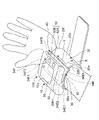
- FIG. 1 shows the appearance of the sphygmomanometer 100 according to the embodiment of the present invention.
- the sphygmomanometer 100 is roughly divided into a blood pressure measuring cuff 20 worn around the rod-shaped measured portion 90 (in this example, the left wrist) of the subject, and the outer surface 20a side (particularly, the palm side) of the cuff 20.
- a main body 10 that is integrally attached to the palm side surface 90a) and has an element for measuring blood pressure, and a mounting member 40 that is inserted and arranged between the cuff 20 and the main body 10. There is.
- the cuff 20 has an elongated strip shape (in this example, a rounded rectangle) in the longitudinal direction X in appearance.
- the cuff 20 is a general one, and is composed of an elongated strip-shaped outer cloth (forming the outer surface 20a) and an inner cloth having a shape corresponding to the outer cloth (forming the inner surface 20b). 23 (see FIG. 2) is sandwiched between them, and the peripheral portions of the outer cloth and the inner cloth (including the edge portions 20e and 20f on both sides in the width direction Y) are sewn or welded.
- the “inner surface 20b” of the cuff 20 refers to a surface on the inner peripheral side in a state of surrounding the measured portion 90 in the circumferential direction.
- the “outer surface 20a” described later of the cuff 20 refers to a surface on the outer peripheral side in a state of surrounding the measured portion 90 in the circumferential direction.
- the “longitudinal direction X” means the direction in which the cuff 20 extends in a band shape, and corresponds to the circumferential direction surrounding the measured portion 90 in the mounted state.
- the "width direction Y” means a direction perpendicular to the longitudinal direction X in the XY plane where the cuff 20 spreads, and corresponds to a direction in which the measured portion 90 extends in a rod shape in the mounted state.
- the "thickness direction Z" shown in FIG. 3 described later means a direction perpendicular to both the longitudinal direction X and the width direction Y (that is, the XY surface on which the cuff 20 spreads), and is in the mounted state. It corresponds to the direction perpendicular to the outer peripheral surface of the measured portion 90.
- the XYZ Cartesian coordinate system is also shown in FIG. 3 (the same applies to FIGS. 6 to 10 described later).
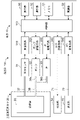
- the main body 10 includes a control unit 110, a display 50, an operation unit 52, a memory 51 as a storage unit, a power supply unit 53, a pressure sensor 31, an oscillation circuit 310, and a pump. 32, a pump drive circuit 320, a valve 33, a valve drive circuit 330, an LED (Light Emitting Diode) drive circuit 340, and an AD (analog to digital) conversion circuit 350 are mounted. ..
- the pressure sensor 31 is connected to the fluid bag 23 contained in the cuff 20 so that the fluid can flow through one air pipe 37.
- the air pipe 38 is a general term including these air pipes 38a and 38b.
- the display 50 and the operation unit 52 are arranged on the top surface (the surface far from the cuff 20) 10a of the main body 10.
- the display 50 is composed of an LCD (Liquid Crystal Display) and displays predetermined information according to a control signal from the control unit 110.
- the display 50 is a systolic blood pressure SBP (Systolic Blood Pressure, unit; mmHg), a diastolic blood pressure DBP (Diastolic Blood Pressure, unit; mmHg), a pulse rate (unit; beat / min), and a subject.
- SBP Synstolic Blood Pressure
- DBP Diastolic Blood Pressure
- the result of vein authentication for is displayed.
- the display 50 may be an organic EL (ElectroLuminescence) display or may include an LED.
- the operation unit 52 includes a measurement switch 52A for receiving an instruction to start / stop blood pressure measurement and a record call switch 52B, and inputs an operation signal according to the user's instruction to the control unit 110.
- a measurement switch 52A for receiving an instruction to start / stop blood pressure measurement
- a record call switch 52B for inputs an operation signal according to the user's instruction to the control unit 110.
- the measurement switch 52A is pressed, an operation signal indicating that the blood pressure measurement should be started is input to the control unit 110, and the control unit 110 starts the blood pressure measurement described later (when the blood pressure measurement is completed, the blood pressure measurement is completed. It will stop automatically.).
- the control unit 110 urgently stops the blood pressure measurement.
- the record call switch 52B is pressed, the past blood pressure measurement result recorded in the memory 51 is called and displayed on the display 50.
- the memory 51 shown in FIG. 2 stores program data for controlling the sphygmomanometer 100, setting data for setting various functions of the sphygmomanometer 100, data of blood pressure value measurement results, and the like. Further, the memory 51 is used as a work memory or the like when a program is executed.
- the control unit 110 includes a CPU (Central Processing Unit) as a processor and controls the operation of the entire blood pressure monitor 100. Specifically, the control unit 110 works as a pressure control unit according to a program for controlling the sphygmomanometer 100 stored in the memory 51, and the pump 32 as a pressure device in response to an operation signal from the operation unit 52. And control to drive the valve 33. Further, the control unit 110 functions as a blood pressure calculation unit, calculates a blood pressure value based on the output of the pressure sensor 31, and controls the display 50 and the memory 51. The specific method of measuring blood pressure will be described later.
- a CPU Central Processing Unit
- the pressure sensor 31 is a piezo resistance type pressure sensor in this example, and the pressure of the fluid bag 23 contained in the cuff 20 (this is referred to as “cuff pressure Pc”) through the air pipe 37 is electrified by the piezo resistance effect. Output as a resistor.
- the oscillation circuit 310 oscillates at an oscillation frequency corresponding to the electric resistance from the pressure sensor 31.
- the control unit 110 obtains the cuff pressure Pc according to the oscillation frequency.
- the pump 32 is driven by the pump drive circuit 320 based on the control signal given from the control unit 110, and supplies air to the fluid bag 23 contained in the cuff 20 through the air pipe 38. As a result, the pressure (cuff pressure Pc) of the fluid bag 23 is pressurized.
- the valve 33 is composed of a normally open type solenoid valve, is driven by a valve drive circuit 330 based on a control signal given from the control unit 110, and discharges or seals the air in the fluid bag 23 through the air pipe 38. It opens and closes to control the cuff pressure.
- the LED drive circuit 340 drives the floodlight unit 34 via the wiring 71 based on the control signal given from the control unit 110. Further, the AD conversion circuit 350 AD-converts an electric signal representing an image including a vein pattern from the light receiving unit 35 and inputs it to the control unit 110. The configuration of the light projecting unit 34 and the light receiving unit 35 will be described later.
- the power supply unit 53 supplies electric power to the control unit 110, the display 50, the memory 51, the pressure sensor 31, the pump 32, the valve 33, and other parts in the main body 10.
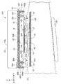
- FIG. 3 is a schematic view showing a cross section along the width direction of the cuff 20 (the direction in which the measured portion 90 extends) with the sphygmomanometer 100 attached to the measured portion 90.
- the cross section inside the main body 10 and the cuff 20 is not shown.
- the mounting member 40 includes a plate portion 41 arranged along the outer surface 20a of the cuff 20.
- the plate portion 41 is attached to the outer surface 20a of the cuff 20 with an adhesive (not shown).
- the end edge regions 40e and 40f on both sides of the mounting member 40 project outward in the width direction Y from the edge portions 20e and 20f on both sides of the cuff 20.
- the end edge region 40e on one side is provided with an outer wall surface 40e1 projecting toward the measurement site 90 and an inner side wall 40e2 projecting parallel to the outer wall surface 40e1.
- a row of LEDs 34E forming a light projecting unit 34 is mounted in an area between the outer wall 40e1 and the inner side wall 40e2 in the edge region 40e. As a result, the row of LEDs 34E is arranged along one side edge 20e of the cuff 20 while being protected by the outer wall 40e1 and the inner side wall 40e2.
- the other end edge region 40f is provided with an outer wall surface 40f1 projecting toward the measured portion 90 and an inner side wall 40f2 projecting parallel to the outer wall surface 40f1.
- a row of LEDs 34F forming a light projecting unit 34 is mounted in a region of the end side region 40f between the outer wall 40f1 and the inner side wall 40f2.
- the LED row 34F is arranged along the other side edge 20f of the cuff 20 in a state of being protected by the outer wall 40f1 and the inner side wall 40f2.
- Flexible boards including wiring 71 (not shown) extending to the main body 10 are connected to the LED rows 34E and 34F, respectively.
- the plate portion 41 and the outer wall 40e1, the inner side wall 40e2, the outer wall surface 40f1, and the inner side wall 40f2 are made of an integrally molded synthetic resin (for example, ABS (acrylonitrile butadiene styrene)). Therefore, in the example using this mounting member 40, the light projecting unit 34 (LED rows 34E, 34F) can be arranged along the edge portions 20e, 20f of the cuff 20 with a simple configuration.
- ABS acrylonitrile butadiene styrene
- the tips of the outer side wall 40e1, the inner side wall 40e2, the outer wall 40f1, and the inner side wall 40f2 are the measured part 90 (in this example, the bottom surface 10b of the main body 10). It is curved in the circumferential direction along the palm side surface 90a). In FIG. 3, the tips of the outer wall 40e1, the inner side wall 40e2, the outer wall 40f1, and the inner side wall 40f2 of the mounting member 40 are drawn apart from the measured portion 90 (in this example, the palm side surface 90a) for convenience. However, in the actual wearing state, it is in close contact with the palm side surface 90a.
- the air pipes 37 and 38 connect the main body 10 and the cuff 20 through a through hole (not shown) provided in the plate portion 41.
- the light projecting unit 34 is composed of rows of LEDs 34E and 34F arranged along the edges 20e and 20f on both sides of the cuff 20 in the width direction Y, respectively. ..
- the row 34E of LEDs on one side contains five LEDs 34E1, 34E2, ..., 34E5.
- the row 34F of the LEDs on the other side also includes five LEDs 34F1, 34F2, ..., 34F5.
- the light projecting portion 34 is not arranged in the central region of the cuff 20 (the region between the edge portions 20e and 20f on both sides) in the width direction Y.
- the light projecting unit 34 (LED rows 34E, 34F) can irradiate the peripheral 92e, 92f of the target region 92 of the measured portion 90 shown in FIG. 3 with the light Le, Lf.
- the light Le and Lf to be irradiated near infrared light (about 700 nm to about 2500 nm), particularly light having a wavelength of 850 nm is used.
- the light receiving portion 35 is provided in a sheet shape along the specific portion 20b1 of the inner surface 20b of the cuff 20 facing the target region 92.
- the target region 92 refers to a region of the measurement site 90 where the vein pattern should be acquired.
- the light receiving unit 35 includes a sheet-shaped image pickup element 35B arranged along the specific portion 20b1 of the inner surface 20b of the cuff 20, and a target region 92 of the image pickup element 35B. It includes a sheet-shaped image sensor 35A arranged along a surface facing the surface of the image sensor 35A.
- the image pickup device 35B is attached to the specific portion 20b1 of the cuff 20 by an adhesive (not shown).
- the image pickup element 35A is attached to the image pickup element 35B and the specific portion 20b1 of the cuff 20 around the image pickup element 35B by an adhesive (not shown).
- the image forming element 35A transmits light in one direction Z (corresponding to the thickness direction Z of the cuff 20) perpendicular to the surface on which the image forming element 35A extends, while in a direction other than the one direction Z. Block the light of.
- an imaging element 35A for example, an all-round privacy filter manufactured by Asdec Co., Ltd. can be used.
- the image pickup device 35B receives the light transmitted through the image pickup element 35A and outputs an electric signal representing the received light.
- an image sensor 35B As such an image sensor 35B, a thin image sensor manufactured by Japan Display Co., Ltd. can be used. In this example, the image sensor 35B outputs an electrical signal representing an image including the vein pattern of the target region 92.
- a flexible substrate (including wiring 72) (not shown) extending to the main body 10 is connected to the image sensor 35B.
- the cuff 20 is attached in such a manner that the longitudinal direction X of the cuff 20 surrounds the outer peripheral surface of the measured site (left wrist in this example) 90 and covers the target region 92 where the vein 93 exists. Will be done.
- the cuff 20 is fixed so as not to loosen by a hook-and-loop fastener (not shown).
- the measured site 90 refers to a site through which the artery 91 to be measured for blood pressure passes.
- the target region 92 refers to the region of the measured site 90 where the vein pattern should be acquired.
- the image sensor 35A, the image sensor 35B, the cuff 20 containing the fluid bag 23, and the main body 10 are present in the thickness direction Z with respect to the palm side surface 90a of the measurement site 90. Line up in order.
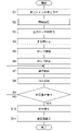
- FIG. 4 shows an operation flow when a subject performs blood pressure measurement including vein authentication with a sphygmomanometer 100. It is assumed that the vein pattern obtained in advance for the user's left wrist is registered (stored) in the memory 51 as the reference vein pattern Pr (schematically shown in FIG. 5C).
- control unit 110 When the user instructs the measurement start by the measurement switch 52A provided on the main body 10 while the cuff 20 is attached to the measurement site 90 (step S1 in FIG. 4), the control unit 110 first receives the current subject. (Step S2 in FIG. 4).
- the control unit 110 drives the light projecting unit 34 (LED rows 34E, 34F) by the LED drive circuit 340, and is shown in FIG.
- Light Le and Lf are irradiated to the periphery 92e and 92f of the target region 92 of the measurement site 90.
- the light receiving unit 35 image sensor 35A, image sensor 35B
- An image including (schematically shown in FIG. 5B) is obtained.
- the control unit 110 acts as an authentication unit to compare the vein pattern Px contained in the image with the pre-registered reference vein pattern Pr for the subject. Perform vein recognition. This identifies whether or not the subject currently being measured is the same person as the user having the pre-registered reference vein pattern Pr. Since the vein authentication itself using the pattern recognition technique is a known technique, detailed description thereof will be omitted.
- the control unit 110 measures the blood pressure in FIG. Returning to the flow, the blood pressure measurement process proceeds as follows.
- control unit 110 first initializes (step S3 in FIG. 4). Specifically, the control unit 110 initializes the processing memory area, stops the pump 32, and adjusts the pressure sensor 31 to 0 mmHg with the valve 33 open (the atmospheric pressure is set to 0 mmHg). I do.
- control unit 110 acts as a pressure control unit, closes the valve 33 (step S4), drives the pump 32, and starts pressurizing the cuff 20 (step S5). That is, the control unit 110 supplies air from the pump 32 to the cuff 20 (the fluid bag 23 contained therein) through the air pipe 38.
- the pressure sensor 31 acts as a pressure detection unit to detect the pressure of the fluid bag 23 through the air pipe 37.
- the control unit 110 controls the pressurizing speed by the pump 32 based on the output of the pressure sensor 31. This pressurization compresses the artery 91 passing through the measurement site 90 to prevent ischemia.
- the pressure (cuff pressure Pc) of the cuff 20 (fluid bag 23) is a predetermined value (a value sufficiently higher than the assumed blood pressure value of the subject) based on the output of the pressure sensor 31.
- the pump 32 is stopped when the previously measured blood pressure value of the subject plus 40 mmHg) is reached (step S6).
- control unit 110 gradually opens the valve 33 (step S7 in FIG. 4).
- the cuff pressure Pc is reduced at a substantially constant speed.
- a pulse wave signal fluctuation component as pulse wave information due to the pulse wave is superimposed on the cuff pressure Pc detected through the air pipe 37 by the pressure sensor 31.
- the control unit 110 functions as a blood pressure calculation unit to extract a pulse wave signal (variable component) superimposed on the cuff pressure Pc, and based on the pulse wave signal acquired at this time, for example.
- An attempt is made to calculate the blood pressure value (systolic blood pressure SBP (Systolic Blood Pressure) and diastolic blood pressure DBP (Diastolic Blood Pressure)) by a known oscillometric method (step S8 in FIG. 4). Further, in this example, the control unit 110 calculates the pulse rate (beat / min) based on the pulse wave signal.
- control unit 110 repeats the processes of steps S7 to S9 until it can be calculated.
- control unit 110 acts as a pressure control unit, opens the valve 33, and rapidly expels the air in the cuff 20 (fluid bag 23). Control to exhaust (step S10).
- control unit 110 displays the calculated blood pressure value and pulse rate on the display 50 (step S11), and controls the storage of the blood pressure value and the pulse rate in the memory 51.
- the blood pressure value and the pulse rate were calculated in the process of depressurizing the cuff 20 (fluid bag 23), but the present invention is not limited to this, and the blood pressure value is calculated in the process of pressurizing the cuff 20 (fluid bag 23). And the pulse rate may be calculated.
- the light projecting portions 34 (LED rows 34E, 34F) are arranged only along the edges 20e, 20f on one side or both sides of the cuff 20 in the width direction Y. That is, the light projecting portion 34 is not arranged in the central region of the cuff 20 (the region between the edge portions 20e and 20f on both sides) in the width direction Y. Therefore, for example, even when the light emitting unit 34 includes a row of light emitting diodes (LEDs) having a thickness of about 1 mm to 2 mm, the presence of the light emitting unit 34 (rows of LEDs 34E, 34F) presses the cuff 20. It does not impair performance.
- LEDs light emitting diodes
- the light receiving unit 35 (image sensor 35A, image sensor 35B) is provided in a sheet shape along a specific portion 20b1 of the inner surface 20b of the cuff 20 facing the target region 92. Therefore, the presence of the light receiving portion 35 does not impair the compression performance of the cuff 20. Therefore, according to this sphygmomanometer 100, the blood pressure can be measured accurately.
- vein authentication can be performed and blood pressure can be measured accurately.
- the main body 10 is integrally attached to the side of the cuff 20 opposite to the measured portion 90. Therefore, the sphygmomanometer 100 is, for example, a tabletop sphygmomanometer (the main body is provided apart from the blood pressure measuring cuff, and is connected to the fluid bag of the cuff so that fluid can flow through a flexible tube. Compared to the type of blood pressure monitor), it is more compact. Further, in the sphygmomanometer 100, the lengths of the wirings 71 and 72 connecting the light emitting unit 34, the light receiving unit 35 and the main body 10 are relatively short, and the reliability of the wirings 71 and 72 is improved.
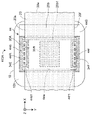
- FIG. 6 shows a portion including the main body 10 of the sphygmomanometer (indicated by reference numeral 100A) of the modified example 1 in which the sphygmomanometer 100 is modified, as viewed from the back side (the side in contact with the measured portion 90).
- the sphygmomanometer 100A is different in that the flexible substrate 44 having a rectangular frame shape is provided as the mounting member instead of the mounting member 40 described above.
- the main body 10 and the cuff 20 are the same as those in the blood pressure monitor 100.
- FIG. 6 and FIGS. 7A and 7B described below the same components as those in the sphygmomanometer 100 are designated by the same reference numerals, and duplicate description will be omitted.
- FIG. 7A shows the planar layout of the flexible substrate 44 along the XY plane on which the cuff 20 spreads.
- FIG. 7B schematically shows a cross section (end face) of the VIIB-VIIB line arrow in FIG. 7A.
- the flexible substrate 44 includes a polyimide resin layer 44B provided with wiring 71 (not shown in FIGS. 7A and 7B) and a light-shielding elastomer layer 44A laminated on the polyimide resin layer 44B. And include.
- the thickness of each layer in FIG. 7B is exaggerated for easy understanding.
- a substantially rectangular central opening 44w is formed in a region where the polyimide resin layer 44B and the elastomer layer 44A overlap.
- the flexible substrate 44 has a rectangular frame-like shape that surrounds the central opening 44w as a whole.
- the edge regions 44e and 44f of the flexible substrate 44 partially project from the side facing the central opening 44w toward the central opening 44w with respect to the direction along the longitudinal direction X. It has the engaged regions 44e1 and 44f1.
- the engagement regions 44e1 and 44f1 are flexed and arranged along the inner surface 20b of the cuff 20.
- the flexible substrate 44 and the cuff 20 are engaged with each other, and the flexible substrate 44 can be easily positioned with respect to the cuff 20.
- the image pickup element 35B and the image pickup element 35A forming the light receiving portion 35 are attached to the specific portion 20b1 of the inner surface 20b of the cuff 20 in this order.
- the main body 10 is integrally attached to the outer surface 20a of the cuff 20. This facilitates assembly.
- the image pickup element 35B and the image pickup element 35A forming the light receiving portion 35 may be attached in advance to the specific portion 20b1 of the inner surface 20b of the cuff 20. ..
- the edge regions 44e and 44f on both sides with respect to the width direction Y of the flexible substrate 44 are the same as in the mounting member 40, with respect to the width direction Y from the edge portions 20e and 20f on both sides of the cuff 20. It protrudes outward.
- the LED rows 34E and 34F forming the light projecting unit 34 are mounted on the edge regions 44e and 44f, respectively. That is, as in the sphygmomanometer 100, the LED rows 34E and 34F are arranged only along the edges 20e and 20f on one or both sides of the cuff 20 in the width direction Y. As a result, even with this sphygmomanometer 100A, the light projecting unit 34 (LED rows 34E, 34F) can be arranged along the edges 20e, 20f of the cuff 20 with a simple configuration.
- the cuff 20 is attached in such a manner that the cuff 20 surrounds the measured portion 90 of the subject in the circumferential direction and covers the target region 92.
- the end side regions 44e and 44f are pressed against the palm side surface 90a, and the bending of the engaging regions 44e1 and 44f1 is substantially eliminated. Therefore, the light projecting unit 34 (LED rows 34E, 34F) can irradiate the peripheral 92e, 92f of the target region 92 of the measured portion 90 with the light Le, Lf, similarly to the sphygmomanometer 100.
- the light receiving unit 35 (image sensor 35A, image sensor 35B) can obtain an image including the vein pattern Px of the target region 92. Further, the presence of the light projecting unit 34 and the light receiving unit 35 does not impair the compression performance of the cuff 20. Therefore, according to this sphygmomanometer 100A, vein authentication can be performed and blood pressure can be measured with high accuracy, as in the case of the sphygmomanometer 100.
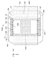
- FIG. 8 shows a portion including the main body 10 of the sphygmomanometer (indicated by reference numeral 100B) of the modified example 2 in which the sphygmomanometer 100 is modified, as viewed from the back side (the side in contact with the measured portion 90).
- the sphygmomanometer 100B is provided with a rectangular plate-shaped flexible substrate 44'in place of the above-mentioned mounting member 40 as the mounting member.
- the main body 10 and the cuff 20 are the same as those in the blood pressure monitor 100.
- FIG. 8 and FIGS. 9A and 9B described below the same components as those in the sphygmomanometer 100 are designated by the same reference numerals, and duplicate description will be omitted.
- FIG. 9A shows the planar layout of the flexible substrate 44'along the XY plane on which the cuff 20 spreads.
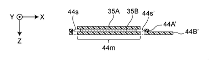
- 9B shows the IXB-IXB line arrow cross section (end face) in FIG. 9A.
- the flexible substrate 44' is a polyimide resin layer 44B' provided with wiring 71 (not shown in FIGS. 9A and 9B) and a light-shielding layer 44B'attached on top of the polyimide resin layer 44B'. It contains an elastomer layer 44A'.
- the polyimide resin layer 44B' is formed in a shape that occupies substantially the entire area of the rectangle (excluding the slits 44s and 44s' described later).
- the elastomer layer 44A' is formed in a rectangular frame shape.
- the image pickup element 35B and the image pickup element 35A forming the light receiving portion 35 in the mounting area 44 m are stacked and attached in this order.
- the thickness of each layer in FIG. 9B is exaggerated for easy understanding.
- the flexible substrate 44' the light emitting portion 34 (LED rows 34E, 34F) and the light receiving portion 35 (imaging element 35A) in the direction along the longitudinal direction X of the cuff 20.
- the pair of slits 44s, 44s'for passing the cuff 20 are formed in the portions corresponding to both sides of the mounting area 44m on which the image sensor 35B) is mounted.
- the dimensions of the slits 44s and 44s' are set to be slightly larger than the dimensions of the cuff 20 in the width direction Y with respect to the direction along the width direction Y of the cuff 20.
- the specific portion 20b1 of the cuff 20 is on the back side (the side opposite to the side facing the measured portion 90) of the mounting area 44m of the flexible substrate 44'. ), And the pair of slits 44s and 44s' are passed through the pair of slits 44s and 44s' from the back surface side so as to extend to the side facing the measured portion 90.
- the flexible substrate 44'and the cuff 20 are engaged with each other, and the flexible substrate 44'is easily positioned with respect to the cuff 20.
- the light projecting unit 34 LED rows 34E, 34F
- the light receiving unit 35 imaging element 35A, image pickup element 35B
- the main body 10 is integrally attached to the outer surface 20a of the cuff 20.
- the edge regions 44e ′ and 44f ′ on both sides with respect to the width direction Y of the flexible substrate 44 ′ have widths from the edges 20e and 20f on both sides of the cuff 20 as in the mounting member 40, respectively. It protrudes outward with respect to the direction Y.
- the LED rows 34E and 34F forming the light projecting unit 34 are mounted on the edge regions 44e'and 44f', respectively. That is, as in the sphygmomanometer 100, the LED rows 34E and 34F are arranged only along the edges 20e and 20f on one or both sides of the cuff 20 in the width direction Y.
- the light projecting unit 34 (LED rows 34E, 34F) can be arranged along the edges 20e, 20f of the cuff 20 with a simple configuration. Further, the light receiving unit 35 (image sensor 35A, image sensor 35B) can be arranged along the specific portion 20b1 facing the target region 92.
- the cuff 20 is attached in such a manner that the cuff 20 surrounds the measured portion 90 of the subject in the circumferential direction and covers the target region 92.
- the light projecting unit 34 LED rows 34E, 34F
- the light receiving unit 35 image sensor 35A, image sensor 35B
- the vein pattern Px of the target region 92 can be obtained by the light receiving unit 35.
- vein authentication can be performed and blood pressure can be measured with high accuracy, as in the case of the sphygmomanometer 100.
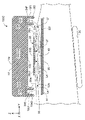
- FIG. 10 shows the sphygmomanometer 100C of the modification 3 which is a modification of the sphygmomanometer 100, corresponding to FIG.
- this sphygmomanometer 100C of the bottom surface 10b of the main body (indicated by reference numeral 10'), the edge regions 10e and 10f protruding outward in the width direction Y from the edges 20e and 20f on both sides of the cuff 20, respectively.
- Rows 34E and 34F of LEDs forming the light projecting unit 34 are arranged.
- the one end edge region 10e is provided with an outer wall surface 10e1 projecting toward the measured portion 90 and an inner side wall 10e2 projecting parallel to the outer wall surface 10e1.
- a row of LEDs 34E forming a light projecting unit 34 is mounted in an area between the outer wall surface 10e1 and the inner side wall 10e2 in the edge region 10e. Thereby, the LED row 34E is arranged along the one-sided edge 20e of the cuff 20 in a state of being protected by the outer wall 10e1 and the inner side wall 10e2.
- the other end edge region 10f is provided with an outer wall surface 10f1 projecting toward the measured portion 90 and an inner side wall 10f2 projecting parallel to the outer wall surface 10f1.
- a row of LEDs 34F forming a light projecting unit 34 is mounted in a region of the edge region 10f between the outer wall 10f1 and the inner side wall 10f2. As a result, the row of LEDs 34F is arranged along the other side edge 20f of the cuff 20 in a state of being protected by the outer wall 10f1 and the inner side wall 10f2. Flexible boards (including wiring 71) (not shown) extending to the main body 10 are connected to the LED rows 34E and 34F, respectively.
- the tips of the outer side wall 10e1, the inner side wall 10e2, the outer wall 10f1, and the inner side wall 10f2 are the measured part 90 (in this example, the palm side surface 90a) like the bottom surface 10b of the main body 10. It is curved in the circumferential direction along.
- vein authentication can be performed and blood pressure can be measured with high accuracy.
- the configuration can be simplified.
- the present inventor has a commercially available wrist-type blood pressure monitor (manufactured by Omron Healthcare Co., Ltd., product number HEM-6220), a blood pressure monitor 100A of the present invention (particularly, the above-mentioned modification 1), and a comparative example blood pressure monitor (this). Was represented by the symbol 100X), and a verification experiment was conducted to compare the blood pressure measurement accuracy.
- the main body and cuff of the wrist type sphygmomanometer (product number HEM-6220) were diverted as the main body 10 and cuff 20. Further, a flexible substrate 44 was prepared, and the sphygmomanometer 100A was configured as shown in FIG.
- the main body and cuff of the wrist type sphygmomanometer (product number HEM-6220) were diverted as the main body 10 and the cuff 20 (for convenience, the same components as those in the blood pressure monitor 100A are the same. It will be described using a reference numeral.)
- a flexible substrate for the sphygmomanometer 100X (which is represented by reference numeral 44X)
- in the flexible substrate 44 in FIG. I prepared the equivalent of arranging along the side).
- the flexible substrate 44X was arranged along the specific portion 20b1 of the inner surface 20b of the cuff 20 facing the target region 92 to form the sphygmomanometer 100X of the comparative example.
- the row of LEDs forming the light projecting unit 34 is not only the edge regions 44e and 44f but also the central region of the cuff 20 (edges 20e and 20f on both sides) in the width direction Y. It is also located in the area between).
- the measured value of the sphygmomanometer 100X in the comparative example is about 10 mmHg higher than the measured value of the commercially available wrist type sphygmomanometer.
- the row of LEDs forming the light projecting unit 34 is not only the edge regions 44e and 44f but also the central region of the cuff 20 (edges 20e on both sides, 20e on both sides) in the width direction Y. It is considered that this is because the compression performance of the cuff 20 is impaired because it is also arranged in the region between 20f).
- the sphygmomanometer 100A of the present invention substantially the same measured value is obtained as compared with the measured value of the commercially available wrist type sphygmomanometer. It is considered that the reason for this is that the edges 20e and 20f on both sides of the cuff 20 contribute less to the compression performance than the central region in the width direction Y in the first place. Therefore, it is considered that even if the rows 34E and 34F of the LEDs forming the light projecting portion 34 are arranged along the edge portions 20e and 20f on both sides of the cuff 20, there is almost no influence on the measured value.
- the light projecting portions 34 are arranged along the edge portions 20e and 20f on both sides of the cuff 20, but the present invention is not limited to this. If an image containing the vein pattern Px of the target region 92 is clearly obtained, it may be arranged only along one edge 20e or 20f.
- the measurement site 90 is assumed to be the left wrist, but the present invention is not limited to this.
- the measurement site 90 may be a right wrist, an upper limb such as an upper arm, or a lower limb such as an ankle.
- the main bodies 10 and 10' are integrally attached to the cuff 20 (the side opposite to the measured portion 90), but the present invention is not limited to this.
- the sphygmomanometer of the present invention is a desktop sphygmomanometer, that is, a type in which the main body is provided apart from the cuff and is connected to the fluid bag of the cuff via a flexible tube so that fluid can flow. Even so, it can be configured.
Landscapes
- Health & Medical Sciences (AREA)
- Life Sciences & Earth Sciences (AREA)
- Cardiology (AREA)
- Engineering & Computer Science (AREA)
- General Health & Medical Sciences (AREA)
- Physics & Mathematics (AREA)
- Biomedical Technology (AREA)
- Heart & Thoracic Surgery (AREA)
- Medical Informatics (AREA)
- Molecular Biology (AREA)
- Surgery (AREA)
- Animal Behavior & Ethology (AREA)
- Pathology (AREA)
- Public Health (AREA)
- Veterinary Medicine (AREA)
- Biophysics (AREA)
- Vascular Medicine (AREA)
- Physiology (AREA)
- Ophthalmology & Optometry (AREA)
- Dentistry (AREA)
- Measuring Pulse, Heart Rate, Blood Pressure Or Blood Flow (AREA)
- Measurement Of The Respiration, Hearing Ability, Form, And Blood Characteristics Of Living Organisms (AREA)
Abstract
Description
被験者について静脈認証を行う機能を有する血圧計であって、
帯状に長手方向に延在し、被験者の棒状の被測定部位を周方向に取り巻いて、上記被測定部位のうち静脈が存するターゲット領域を覆う態様で装着される血圧測定用カフと、
上記カフが広がる面内で上記長手方向に対して垂直な幅方向に関して、上記カフの片側または両側の縁部に沿って配置され、上記被測定部位の上記ターゲット領域の周辺へ光を照射する投光部と、
上記カフの内面のうち上記ターゲット領域に対向する特定部分に沿ってシート状に設けられ、上記ターゲット領域によって散乱または反射された光を受けて、上記ターゲット領域の静脈パターンを含む像を得る受光部と、
上記像に含まれた上記静脈パターンを、予め登録されている基準静脈パターンと比較して、上記被験者について静脈認証を行う認証部と
を備えたことを特徴とする。
上記受光部は、
上記カフの上記内面のうち上記特定部分に沿って配置されたシート状の撮像素子と、
上記撮像素子の上記ターゲット領域に対向する側の面に沿って配置されたシート状の結像素子とを含み、
上記結像素子は、この結像素子が延在する面に対して垂直な一方向の光を透過させる一方、上記一方向以外の方向の光を遮断し、
上記撮像素子は、上記結像素子を透過した光を受けて、上記ターゲット領域の上記静脈パターンを含む像を表す電気信号を出力する
ことを特徴とする。
上記カフの外面に沿って配置された取付部材を備え、
上記取付部材の上記幅方向に関して両側の端辺領域は、上記カフの上記両側の縁部からそれぞれ上記幅方向に関して外向きに突出し、
上記投光部は、上記取付部材の上記端辺領域に搭載されることによって、上記カフの上記縁部に沿って配置されている
ことを特徴とする。
上記取付部材は、中央開口を取り囲む矩形枠状のフレキシブル基板であり、
上記フレキシブル基板の上記端辺領域は、上記中央開口に対向する辺から、上記長手方向に沿った方向に関して部分的に上記中央開口へ向かって突出した係合領域を有し、
上記係合領域は、撓んで上記カフの内面に沿って配置され、上記フレキシブル基板と上記カフとを係合している
ことを特徴とする。
上記カフの内面に沿って配置された矩形状のフレキシブル基板を備え、
上記フレキシブル基板の上記幅方向に関して両側の端辺領域は、上記カフの上記両側の縁部からそれぞれ上記幅方向に関して外向きに突出し、
上記投光部は、上記フレキシブル基板の上記端辺領域に搭載されることによって、上記カフの上記縁部に沿って配置され、
上記受光部は、上記フレキシブル基板の上記端辺領域に挟まれた内部領域に搭載されることによって、上記ターゲット領域に対向する上記特定部分に沿って配置されている
ことを特徴とする。
上記フレキシブル基板は、上記カフの上記長手方向に沿った方向に関して上記投光部と上記受光部とを搭載した搭載領域の両側に相当する部位に、上記カフを通すための一対のスリットを有し、
上記カフは、上記特定部分が上記フレキシブル基板の上記搭載領域の背面側に重なり、上記背面側から上記一対のスリットをそれぞれ通して上記被測定部位に対向する側へ延在する態様で、上記被測定部位を周方向に取り巻くようになっている
ことを特徴とする。
上記カフの外面側に一体に取り付けられた本体を備え、
上記本体は、
上記認証部と、
上記カフに流体を供給して加圧し、または、上記カフから流体を排出して減圧する制御を行う圧力制御部と、
上記カフの圧力を検出する圧力検出部と、
上記圧力検出部の出力に基づいて血圧を算出する血圧算出部と
を搭載していることを特徴とする。
図1は、この発明の一実施形態の血圧計100の外観を示している。この血圧計100は、大別して、被験者の棒状の被測定部位90(この例では、左手首)を取り巻いて装着される血圧測定用カフ20と、このカフ20の外面20a側(特に、手のひら側の掌側面90aに対応する部分)に一体に取り付けられ、血圧測定のための要素を搭載した本体10と、カフ20と本体10との間に介挿して配置された取付部材40とを備えている。
図1によって分かるように、上記カフ20は、外観上、長手方向Xに細長い帯状(この例では、丸角の長方形)の形状を有している。この例では、カフ20は、一般的なものであり、細長い帯状の外布(外面20aをなす)と、この外布に対応する形状をもつ内布(内面20bをなす)とを、流体袋23(図2参照)を挟んで対向させ、それらの外布、内布の周縁部(幅方向Yに関して両側の縁部20e,20fを含む)を縫製または溶着して構成されている。
図2に示すように、本体10は、制御部110と、表示器50と、操作部52と、記憶部としてのメモリ51と、電源部53と、圧力センサ31と、発振回路310と、ポンプ32と、ポンプ駆動回路320と、弁33と、弁駆動回路330と、LED(Light Emitting Diode;発光ダイオード)駆動回路340と、AD(アナログ・ツゥ・デジタル)変換回路350とを搭載している。この例では、圧力センサ31が、1本のエア配管37を介して、カフ20に内包された流体袋23に流体流通可能に接続されている。また、ポンプ32に接続されたエア配管38aと、弁33に接続されたエア配管38bとが合流して、1本のエア配管38になって、流体袋23に流体流通可能に接続されている。エア配管38は、これらのエア配管38a,38bを含む総称である。
図3は、血圧計100が被測定部位90に装着された状態で、カフ20の幅方向(被測定部位90が延在する方向)に沿った断面を示す模式図である。なお、図3において、本体10やカフ20の内部の断面は図示が省略されている。図3中に示すように、取付部材40は、カフ20の外面20aに沿って配置された板部41を備えている。この例では、板部41は、カフ20の外面20aに対して接着剤(図示せず)によって貼り付けられている。取付部材40(板部41)の幅方向Yに関して両側の端辺領域40e,40fは、カフ20の両側の縁部20e,20fからそれぞれ幅方向Yに関して外向きに突出している。片側の端辺領域40eには、被測定部位90へ向かって突出した外側壁40e1と、その外側壁40e1と平行に突出した内側壁40e2とが設けられている。端辺領域40eのうち、外側壁40e1と内側壁40e2との間の領域に、投光部34をなすLEDの列34Eが搭載されている。これにより、LEDの列34Eは、外側壁40e1と内側壁40e2とによって保護された状態で、カフ20の片側の縁部20eに沿って配置されている。同様に、他側の端辺領域40fには、被測定部位90へ向かって突出した外側壁40f1と、その外側壁40f1と平行に突出した内側壁40f2とが設けられている。端辺領域40fのうち、外側壁40f1と内側壁40f2との間の領域に、投光部34をなすLEDの列34Fが搭載されている。これにより、LEDの列34Fは、外側壁40f1と内側壁40f2とによって保護された状態で、カフ20の他側の縁部20fに沿って配置されている。LEDの列34E,34Fには、それぞれ本体10へ延びる図示しないフレキシブル基板(配線71を含む)が接続されている。
この例では、投光部34は、図1中に示すように、幅方向Yに関して、カフ20の両側の縁部20e,20fに沿ってそれぞれ配置されたLEDの列34E,34Fからなっている。片側のLEDの列34Eは、5個のLED34E1,34E2,…,34E5を含んでいる。同様に、他側のLEDの列34Fも、5個のLED34F1,34F2,…,34F5を含んでいる。図1によって分かるように、投光部34は、幅方向Yに関して、カフ20の中央領域(両側の縁部20e,20fの間の領域)には配置されていない。この配置に応じて、投光部34(LEDの列34E,34F)は、図3中に示す被測定部位90のターゲット領域92の周辺92e,92fへ光Le,Lfを照射することができる。この例では、照射する光Le,Lfとしては、近赤外光(約700nm~約2500nm)で、特に波長850nmの光を用いるものとする。
上記カフ20は、図3に示すように、カフ20の長手方向Xが被測定部位(この例では、左手首)90の外周面を取り巻いて、静脈93が存するターゲット領域92を覆う態様で装着される。装着のとき、図示しない面ファスナによって、カフ20が緩まないように固定される。ここで、被測定部位90とは、血圧測定の対象となる動脈91が通っている部位を指す。また、既述のように、ターゲット領域92とは、被測定部位90のうち静脈パターンが取得されるべき領域を指している。この装着状態では、被測定部位90の掌側面90aに対して、厚さ方向Zに、結像素子35Aと、撮像素子35Bと、流体袋23を内包したカフ20と、本体10とが、この順に並ぶ。
図4は、被験者が血圧計100によって、静脈認証を含む血圧測定を行う際の動作フローを示している。なお、ユーザの左手首について予め得られた静脈パターンが、基準静脈パターンPr(図5(C)に模式的に示す)としてメモリ51に登録(記憶)されているものとする。
図6は、上記血圧計100を変形した変形例1の血圧計(符号100Aで示す)の本体10を含む部分を、裏側(被測定部位90に接する側)から見たところを示している。この血圧計100Aでは、取付部材として、既述の取付部材40に代えて、矩形枠状のフレキシブル基板44を備えた点が異なっている。本体10、カフ20については、上記血圧計100におけるのと同じである。図6および次に述べる図7A,図7Bにおいて、上記血圧計100におけるのと同じ構成要素には同じ符号を付して、重複する説明を省略する。
図8は、上記血圧計100を変形した変形例2の血圧計(符号100Bで示す)の本体10を含む部分を、裏側(被測定部位90に接する側)から見たところを示している。この血圧計100Bでは、取付部材として、既述の取付部材40に代えて、矩形板状のフレキシブル基板44′を備えた点が異なっている。本体10、カフ20については、上記血圧計100におけるのと同じである。図8および次に述べる図9A,図9Bにおいて、上記血圧計100におけるのと同じ構成要素には同じ符号を付して、重複する説明を省略する。
上述の各例では、本体10とは別に構成された取付部材(取付部材40、フレキシブル基板44または44′)を備えたが、これに限られるものではない。図10は、上記血圧計100を変形した変形例3の血圧計100Cを、図3に対応して示している。この血圧計100Cでは、本体(符号10′で示す)の底面10bのうち、カフ20の両側の縁部20e,20fからそれぞれ幅方向Yに関して外向きに突出した端辺領域10e,10fに、それぞれ投光部34をなすLEDの列34E,34Fが配置されている。
本発明者は、市販の手首式血圧計(オムロンヘルスケア株式会社製、品番HEM-6220)と、本発明(特に、上述の変形例1)の血圧計100Aと、比較例の血圧計(これを符号100Xで表す)とについて、血圧測定精度を比較する検証実験を行った。
(表1)

20 血圧測定用カフ
23 流体袋
31 圧力センサ
32 ポンプ
33 弁
34 投光部
34E,34F LEDの列
35 受光部
35A 結像素子
35B 撮像素子
40 取付部材
44,44′ フレキシブル基板
100,100A,100B,100C 血圧計
Claims (7)
- 被験者について静脈認証を行う機能を有する血圧計であって、
帯状に長手方向に延在し、被験者の棒状の被測定部位を周方向に取り巻いて、上記被測定部位のうち静脈が存するターゲット領域を覆う態様で装着される血圧測定用カフと、
上記カフが広がる面内で上記長手方向に対して垂直な幅方向に関して、上記カフの片側または両側の縁部に沿って配置され、上記被測定部位の上記ターゲット領域の周辺へ光を照射する投光部と、
上記カフの内面のうち上記ターゲット領域に対向する特定部分に沿ってシート状に設けられ、上記ターゲット領域によって散乱または反射された光を受けて、上記ターゲット領域の静脈パターンを含む像を得る受光部と、
上記像に含まれた上記静脈パターンを、予め登録されている基準静脈パターンと比較して、上記被験者について静脈認証を行う認証部と
を備えたことを特徴とする血圧計。 - 請求項1に記載の血圧計において、
上記受光部は、
上記カフの上記内面のうち上記特定部分に沿って配置されたシート状の撮像素子と、
上記撮像素子の上記ターゲット領域に対向する側の面に沿って配置されたシート状の結像素子とを含み、
上記結像素子は、この結像素子が延在する面に対して垂直な一方向の光を透過させる一方、上記一方向以外の方向の光を遮断し、
上記撮像素子は、上記結像素子を透過した光を受けて、上記ターゲット領域の上記静脈パターンを含む像を表す電気信号を出力する
ことを特徴とする血圧計。 - 請求項1または2に記載の血圧計において、
上記カフの外面に沿って配置された取付部材を備え、
上記取付部材の上記幅方向に関して両側の端辺領域は、上記カフの上記両側の縁部からそれぞれ上記幅方向に関して外向きに突出し、
上記投光部は、上記取付部材の上記端辺領域に搭載されることによって、上記カフの上記縁部に沿って配置されている
ことを特徴とする血圧計。 - 請求項3に記載の血圧計において、
上記取付部材は、中央開口を取り囲む矩形枠状のフレキシブル基板であり、
上記フレキシブル基板の上記端辺領域は、上記中央開口に対向する辺から、上記長手方向に沿った方向に関して部分的に上記中央開口へ向かって突出した係合領域を有し、
上記係合領域は、撓んで上記カフの内面に沿って配置され、上記フレキシブル基板と上記カフとを係合している
ことを特徴とする血圧計。 - 請求項1または2に記載の血圧計において、
上記カフの内面に沿って配置された矩形状のフレキシブル基板を備え、
上記フレキシブル基板の上記幅方向に関して両側の端辺領域は、上記カフの上記両側の縁部からそれぞれ上記幅方向に関して外向きに突出し、
上記投光部は、上記フレキシブル基板の上記端辺領域に搭載されることによって、上記カフの上記縁部に沿って配置され、
上記受光部は、上記フレキシブル基板の上記端辺領域に挟まれた内部領域に搭載されることによって、上記ターゲット領域に対向する上記特定部分に沿って配置されている
ことを特徴とする血圧計。 - 請求項5に記載の血圧計において、
上記フレキシブル基板は、上記カフの上記長手方向に沿った方向に関して上記投光部と上記受光部とを搭載した搭載領域の両側に相当する部位に、上記カフを通すための一対のスリットを有し、
上記カフは、上記特定部分が上記フレキシブル基板の上記搭載領域の背面側に重なり、上記背面側から上記一対のスリットをそれぞれ通して上記被測定部位に対向する側へ延在する態様で、上記被測定部位を周方向に取り巻くようになっている
ことを特徴とする血圧計。 - 請求項1から6までのいずれか一つに記載の血圧計において、
上記カフの外面側に一体に取り付けられた本体を備え、
上記本体は、
上記認証部と、
上記カフに流体を供給して加圧し、または、上記カフから流体を排出して減圧する制御を行う圧力制御部と、
上記カフの圧力を検出する圧力検出部と、
上記圧力検出部の出力に基づいて血圧を算出する血圧算出部と
を搭載していることを特徴とする血圧計。
Priority Applications (3)
| Application Number | Priority Date | Filing Date | Title |
|---|---|---|---|
| CN202180054624.XA CN116157066B (zh) | 2020-11-06 | 2021-11-02 | 血压计 |
| DE112021005836.3T DE112021005836T5 (de) | 2020-11-06 | 2021-11-02 | Blutdruckmessgerät |
| US18/117,693 US12490911B2 (en) | 2020-11-06 | 2023-03-06 | Sphygmomanometer |
Applications Claiming Priority (2)
| Application Number | Priority Date | Filing Date | Title |
|---|---|---|---|
| JP2020186052A JP7669667B2 (ja) | 2020-11-06 | 2020-11-06 | 血圧計 |
| JP2020-186052 | 2020-11-06 |
Related Child Applications (1)
| Application Number | Title | Priority Date | Filing Date |
|---|---|---|---|
| US18/117,693 Continuation US12490911B2 (en) | 2020-11-06 | 2023-03-06 | Sphygmomanometer |
Publications (1)
| Publication Number | Publication Date |
|---|---|
| WO2022097629A1 true WO2022097629A1 (ja) | 2022-05-12 |
Family
ID=81457274
Family Applications (1)
| Application Number | Title | Priority Date | Filing Date |
|---|---|---|---|
| PCT/JP2021/040363 Ceased WO2022097629A1 (ja) | 2020-11-06 | 2021-11-02 | 血圧計 |
Country Status (5)
| Country | Link |
|---|---|
| US (1) | US12490911B2 (ja) |
| JP (1) | JP7669667B2 (ja) |
| CN (1) | CN116157066B (ja) |
| DE (1) | DE112021005836T5 (ja) |
| WO (1) | WO2022097629A1 (ja) |
Citations (8)
| Publication number | Priority date | Publication date | Assignee | Title |
|---|---|---|---|---|
| JP2006217930A (ja) * | 2005-02-08 | 2006-08-24 | Nippon Telegr & Teleph Corp <Ntt> | 血圧測定装置 |
| CN202723841U (zh) * | 2012-06-20 | 2013-02-13 | 黑龙江大学 | 手指动脉血压连续检测用传感装置 |
| US20150356339A1 (en) * | 2014-06-09 | 2015-12-10 | Lawrence Livermore National Security, Llc | Multimodal Imaging System And Method For Non-Contact Identification of Multiple Biometric Traits |
| US20160321951A1 (en) * | 2015-04-28 | 2016-11-03 | Samsung Electronics Co., Ltd. | Electronic apparatus, server, and controlling method thereof |
| JP2017510411A (ja) * | 2014-04-04 | 2017-04-13 | アップ−メド ゲーエムベーハー | 血管内の血圧を求める方法、並びに、該方法を実行する装置 |
| JP2018099177A (ja) * | 2016-12-19 | 2018-06-28 | オムロンヘルスケア株式会社 | 生体情報測定装置、生体情報の管理方法、及び、生体情報の管理プログラム |
| JP2018102818A (ja) * | 2016-12-28 | 2018-07-05 | オムロン株式会社 | 血圧計および血圧測定方法並びに機器 |
| JP2020142070A (ja) * | 2019-02-28 | 2020-09-10 | 株式会社アドバンス | 位相差法による連続血圧測定システム |
Family Cites Families (26)
| Publication number | Priority date | Publication date | Assignee | Title |
|---|---|---|---|---|
| JP2001309895A (ja) * | 2000-05-01 | 2001-11-06 | Omron Corp | 血圧計 |
| JP2006011711A (ja) * | 2004-06-24 | 2006-01-12 | Sony Ericsson Mobilecommunications Japan Inc | 認証装置及び携帯端末 |
| KR101031712B1 (ko) * | 2005-06-13 | 2011-04-29 | 가부시키가이샤 히타치세이사쿠쇼 | 정맥 인증 장치 |
| JP2007190272A (ja) * | 2006-01-20 | 2007-08-02 | Fujifilm Corp | 測定装置及びシステム |
| JP2007325842A (ja) * | 2006-06-09 | 2007-12-20 | Nec Corp | 健康管理機能を備えた携帯端末 |
| JP5169643B2 (ja) * | 2008-09-02 | 2013-03-27 | オムロンヘルスケア株式会社 | 電子血圧計および血圧測定制御方法 |
| JP2012200266A (ja) * | 2011-03-23 | 2012-10-22 | Omron Healthcare Co Ltd | 制御装置および認証方法 |
| JP2012210374A (ja) * | 2011-03-31 | 2012-11-01 | Omron Healthcare Co Ltd | 血圧情報測定装置用カフおよびこれを備えた血圧情報測定装置 |
| JP6027716B2 (ja) | 2012-04-03 | 2016-11-16 | 旭光電機株式会社 | 装着型使用者状態情報取得装置 |
| CN106073742A (zh) * | 2013-05-13 | 2016-11-09 | 天津点康科技有限公司 | 一种血压测量系统及方法 |
| US8888714B1 (en) * | 2013-09-20 | 2014-11-18 | Richard Soto | Automatic blood draw system and method |
| JP6075277B2 (ja) * | 2013-12-04 | 2017-02-08 | オムロンヘルスケア株式会社 | ユーザ認証システム |
| JP6225705B2 (ja) * | 2013-12-27 | 2017-11-08 | オムロンヘルスケア株式会社 | 血圧測定用カフおよびそれを備えた血圧計 |
| EP3226780A1 (en) * | 2014-12-04 | 2017-10-11 | Carebay Europe Ltd. | Smart tourniquet |
| JP2017000415A (ja) * | 2015-06-10 | 2017-01-05 | セイコーエプソン株式会社 | 情報取得装置および情報取得方法 |
| KR101796352B1 (ko) * | 2015-06-30 | 2017-12-01 | 김훈 | 정맥 인식 장치 및 이를 이용한 개인 인식 시스템 |
| JP6495153B2 (ja) * | 2015-11-25 | 2019-04-03 | 日本電信電話株式会社 | 同一性判定システム及び同一性判定方法 |
| FR3049090B1 (fr) * | 2016-03-21 | 2021-06-25 | Sebastien Jean Serge Dupont | Dispositif d'authentification biometrique adaptatif par echographie, photographies en lumiere visible de contraste et infrarouge, sans divulgation, a travers un reseau informatique decentralise |
| JP6751666B2 (ja) * | 2016-12-28 | 2020-09-09 | オムロン株式会社 | 血圧計および血圧測定方法並びに機器 |
| KR102700049B1 (ko) * | 2017-02-03 | 2024-08-29 | 삼성전자주식회사 | 생체 정보 인증을 위한 전자 장치 및 시스템 |
| JP2018149091A (ja) * | 2017-03-13 | 2018-09-27 | オムロン株式会社 | 通信装置および血圧測定装置 |
| JP2019000548A (ja) * | 2017-06-19 | 2019-01-10 | オムロンヘルスケア株式会社 | 情報処理装置、生体情報測定装置、情報処理方法及び情報処理プログラム |
| CN208492052U (zh) * | 2017-09-05 | 2019-02-15 | 辽宁领慧科技有限公司 | 一种腕带 |
| WO2019195120A1 (en) | 2018-04-03 | 2019-10-10 | Trustees Of Tufts College | Tactile blood pressure imager |
| WO2020195300A1 (ja) * | 2019-03-26 | 2020-10-01 | 日本電気株式会社 | 生体情報認証システム、生体情報認証方法、認証機器、認証方法、測定機器、測定方法、およびプログラムを記録したコンピュータ読み取り可能な記録媒体 |
| JP3223156U (ja) * | 2019-07-10 | 2019-09-19 | 有限会社アネストシステム | 血圧測定管理システム |
-
2020
- 2020-11-06 JP JP2020186052A patent/JP7669667B2/ja active Active
-
2021
- 2021-11-02 CN CN202180054624.XA patent/CN116157066B/zh active Active
- 2021-11-02 DE DE112021005836.3T patent/DE112021005836T5/de active Pending
- 2021-11-02 WO PCT/JP2021/040363 patent/WO2022097629A1/ja not_active Ceased
-
2023
- 2023-03-06 US US18/117,693 patent/US12490911B2/en active Active
Patent Citations (8)
| Publication number | Priority date | Publication date | Assignee | Title |
|---|---|---|---|---|
| JP2006217930A (ja) * | 2005-02-08 | 2006-08-24 | Nippon Telegr & Teleph Corp <Ntt> | 血圧測定装置 |
| CN202723841U (zh) * | 2012-06-20 | 2013-02-13 | 黑龙江大学 | 手指动脉血压连续检测用传感装置 |
| JP2017510411A (ja) * | 2014-04-04 | 2017-04-13 | アップ−メド ゲーエムベーハー | 血管内の血圧を求める方法、並びに、該方法を実行する装置 |
| US20150356339A1 (en) * | 2014-06-09 | 2015-12-10 | Lawrence Livermore National Security, Llc | Multimodal Imaging System And Method For Non-Contact Identification of Multiple Biometric Traits |
| US20160321951A1 (en) * | 2015-04-28 | 2016-11-03 | Samsung Electronics Co., Ltd. | Electronic apparatus, server, and controlling method thereof |
| JP2018099177A (ja) * | 2016-12-19 | 2018-06-28 | オムロンヘルスケア株式会社 | 生体情報測定装置、生体情報の管理方法、及び、生体情報の管理プログラム |
| JP2018102818A (ja) * | 2016-12-28 | 2018-07-05 | オムロン株式会社 | 血圧計および血圧測定方法並びに機器 |
| JP2020142070A (ja) * | 2019-02-28 | 2020-09-10 | 株式会社アドバンス | 位相差法による連続血圧測定システム |
Also Published As
| Publication number | Publication date |
|---|---|
| DE112021005836T5 (de) | 2023-08-24 |
| JP2022075331A (ja) | 2022-05-18 |
| US20230200669A1 (en) | 2023-06-29 |
| US12490911B2 (en) | 2025-12-09 |
| CN116157066B (zh) | 2025-11-25 |
| JP7669667B2 (ja) | 2025-04-30 |
| CN116157066A (zh) | 2023-05-23 |
Similar Documents
| Publication | Publication Date | Title |
|---|---|---|
| JP6597410B2 (ja) | 生体情報測定装置および生体情報測定方法 | |
| US20100036265A1 (en) | Apparatus and method for measuring blood pressure | |
| KR20160086710A (ko) | 체표압력 및 혈액용적의 동시 측정장치 및 방법 | |
| JP2017153875A (ja) | 生体情報測定装置および生体情報測定方法 | |
| JP6910290B2 (ja) | 振動波形センサ及び波形解析装置 | |
| JP6293927B2 (ja) | センサ | |
| US20140213865A1 (en) | Biological signal measuring system and biological signal measuring apparatus | |
| CN104185442A (zh) | 血压计 | |
| CN113271844A (zh) | 测量动脉系统的功能的装置 | |
| US20220015673A1 (en) | Integrated optical biosensors including molded beam shaping elements | |
| US20220096015A1 (en) | Mobile device, method of controlling the same, and computer program stored in recording medium | |
| JP2022075331A (ja) | 血圧計 | |
| JP5625426B2 (ja) | センサー装置及び生体情報測定装置 | |
| US12446784B2 (en) | Apparatus and method for estimating blood pressure, and sensor for estimating the same | |
| JP2007319343A (ja) | 圧力検出装置 | |
| KR20190088334A (ko) | 생체 신호 측정 장치 | |
| JP6837881B2 (ja) | 生体情報測定装置、方法及びプログラム | |
| US20260041327A1 (en) | Biological information measurement device | |
| CN222091673U (zh) | 检测装置及电子设备 | |
| CN110769747A (zh) | 生物体测定用天线装置、脉搏波测定装置、血压测定装置、设备、生物体信息测定方法、脉搏波测定方法、以及血压测定方法 | |
| JP2019201978A (ja) | センサモジュール、センサモジュールの製造方法、及び血圧測定装置 | |
| JP2020096648A (ja) | 生体関連情報測定装置 | |
| Tuukka et al. | Continuous Blood Pressure Monitoring Using Nonpulsatile Photoplethysmographic Components for Low-Frequency Vascular Unloading | |
| CN120189087A (zh) | 一种佩戴检测的方法、调节机构以及可穿戴设备 | |
| JP2000051163A (ja) | 犬や猫等の動物の非観血型血圧計及び測定法 |
Legal Events
| Date | Code | Title | Description |
|---|---|---|---|
| 121 | Ep: the epo has been informed by wipo that ep was designated in this application |
Ref document number: 21889182 Country of ref document: EP Kind code of ref document: A1 |
|
| WWE | Wipo information: entry into national phase |
Ref document number: 202317014793 Country of ref document: IN |
|
| REG | Reference to national code |
Ref country code: BR Ref legal event code: B01A Ref document number: 112023004307 Country of ref document: BR |
|
| ENP | Entry into the national phase |
Ref document number: 112023004307 Country of ref document: BR Kind code of ref document: A2 Effective date: 20230308 |
|
| 122 | Ep: pct application non-entry in european phase |
Ref document number: 21889182 Country of ref document: EP Kind code of ref document: A1 |
|
| WWG | Wipo information: grant in national office |
Ref document number: 202317014793 Country of ref document: IN |