WO2022097543A1 - 運動支援装置及び運動支援方法 - Google Patents
運動支援装置及び運動支援方法 Download PDFInfo
- Publication number
- WO2022097543A1 WO2022097543A1 PCT/JP2021/039613 JP2021039613W WO2022097543A1 WO 2022097543 A1 WO2022097543 A1 WO 2022097543A1 JP 2021039613 W JP2021039613 W JP 2021039613W WO 2022097543 A1 WO2022097543 A1 WO 2022097543A1
- Authority
- WO
- WIPO (PCT)
- Prior art keywords
- user
- time
- speed
- support device
- exercise
- Prior art date
- Legal status (The legal status is an assumption and is not a legal conclusion. Google has not performed a legal analysis and makes no representation as to the accuracy of the status listed.)
- Ceased
Links
Images




Classifications
-
- A—HUMAN NECESSITIES
- A61—MEDICAL OR VETERINARY SCIENCE; HYGIENE
- A61H—PHYSICAL THERAPY APPARATUS, e.g. DEVICES FOR LOCATING OR STIMULATING REFLEX POINTS IN THE BODY; ARTIFICIAL RESPIRATION; MASSAGE; BATHING DEVICES FOR SPECIAL THERAPEUTIC OR HYGIENIC PURPOSES OR SPECIFIC PARTS OF THE BODY
- A61H1/00—Apparatus for passive exercising; Vibrating apparatus; Chiropractic devices, e.g. body impacting devices, external devices for briefly extending or aligning unbroken bones
- A61H1/02—Stretching or bending or torsioning apparatus for exercising
-
- A—HUMAN NECESSITIES
- A63—SPORTS; GAMES; AMUSEMENTS
- A63B—APPARATUS FOR PHYSICAL TRAINING, GYMNASTICS, SWIMMING, CLIMBING, OR FENCING; BALL GAMES; TRAINING EQUIPMENT
- A63B22/00—Exercising apparatus specially adapted for conditioning the cardio-vascular system, for training agility or co-ordination of movements
- A63B22/02—Exercising apparatus specially adapted for conditioning the cardio-vascular system, for training agility or co-ordination of movements with movable endless bands, e.g. treadmills
-
- A—HUMAN NECESSITIES
- A63—SPORTS; GAMES; AMUSEMENTS
- A63B—APPARATUS FOR PHYSICAL TRAINING, GYMNASTICS, SWIMMING, CLIMBING, OR FENCING; BALL GAMES; TRAINING EQUIPMENT
- A63B24/00—Electric or electronic controls for exercising apparatus of preceding groups; Controlling or monitoring of exercises, sportive games, training or athletic performances
Definitions
- the present invention relates to a technique for supporting the movement of a user.
- Patent Document 1 discloses a walking training device 1 using a treadmill provided with a belt-shaped walking road surface that moves at a set speed. It should be noted that Non-Patent Document 1 discloses that when the floor is moved in synchronization with the movement of the user in a stationary standing state, the movement changes.
- the walking training device 1 described in Patent Document 1 detects the displacement, speed, acceleration, and tension of the sidewalk means 2, and drives the sidewalk means 2 by a feedback control rule based on the detection result and the load characteristic of the sidewalk means 2. Therefore, there is a problem that complicated control is required.
- the present invention has been made to solve such a problem, and provides an exercise support device and an exercise support method that change the load on the body during exercise such as walking or running of a user by simpler control.
- the purpose is.
- the present invention is an exercise support device that supports the user's movement by moving the surface on which the user touches the ground at a set speed, and detects the user's touchdown time and takeoff time to detect the user.
- an exercise support device including a detection means for acquiring the motion pattern of the above and a control means for controlling the speed of the surface in synchronization with the motion pattern.
- the present invention is an exercise support device that supports the user's movement by moving the surface on which the user touches the ground at a set speed, and speed control for controlling the speed of the surface. It is provided with a storage means for storing a pattern, a control means for controlling the speed of the surface by a speed control pattern stored in the storage means, and a notification means for notifying the user of a time point when the user should touch down according to the speed control pattern.
- a storage means for storing a pattern
- a control means for controlling the speed of the surface by a speed control pattern stored in the storage means
- a notification means for notifying the user of a time point when the user should touch down according to the speed control pattern.
- the present invention is an exercise support method for supporting the user's movement by moving the surface to be touched by the user at a set speed, and detects the time when the user touches the ground and the time when the user takes off.
- an exercise support method having a first step of acquiring a user's motion pattern and a second step of controlling the speed of the surface in synchronization with the motion pattern.
- the present invention is an exercise support method for supporting the user's exercise by moving the surface on which the user touches the ground at a set speed, and the above-mentioned surface is subjected to a speed control pattern stored in advance.
- an exercise support method having a first step of controlling a speed and a second step of notifying a user of a time point when the user should touch down according to the speed control pattern.
- an exercise support device and an exercise support method that change the load on the body during exercise such as walking or running of a user by simpler control.
- FIG. 2 It is a block diagram which shows the structure of the exercise support device 1 which concerns on Embodiment 1 of this invention. It is a flowchart which shows the operation of the exercise support apparatus 1 shown in FIG. 2 is a diagram for explaining a first specific example in speed control of a ground plane in step S2 shown in FIG. 2, FIG. 3A is a diagram showing a user's gait, and FIG. 3B is a diagram. It is a waveform diagram which shows the velocity of the contact patch at each step shown in 3 (a). 2 is a diagram for explaining a second specific example in speed control of the ground plane in step S2 shown in FIG. 2, FIG. 4A is a diagram showing a user's gait, and FIG. 4B is a diagram.
- FIG. 5A is a diagram showing a user's gait
- FIG. 5B is a diagram.
- 2 is a diagram for explaining a fourth specific example in speed control of the ground plane in step S2 shown in FIG. 2
- FIG. 6A is a diagram showing a user's gait
- FIG. 6B is a diagram.
- FIG. 1 is a block diagram showing the configuration of the exercise support device 1 according to the first embodiment of the present invention.
- the exercise support device 1 includes an input / output unit T, a bus B connected to the input / output unit T, a detection unit 2 connected to the bus B, a control unit 3, a storage unit 4, and so on. It includes an operation unit 5 and a drive unit 6.
- the drive unit 6 is configured by a treadmill that moves a surface on which the left and right feet of the user touch the ground at a set speed by using two independent annular belts. Will be done.
- the detection unit 2 is installed under, for example, the annular belt or the exercise support device 1, and is composed of a floor reaction force meter that measures the contact force between the user and the ground contact surface.
- a floor reaction force meter that measures the contact force between the user and the ground contact surface.
- the detection unit 2 may be configured by an optical motion capture system that captures a user with a marker attached to the foot.
- an optical motion capture system that captures a user with a marker attached to the foot.
- the detection unit 2 may be configured by a belt tension meter that measures the tension of the annular belt.
- a belt tension meter that measures the tension of the annular belt.
- the control unit 3 is configured by a central processing unit (CPU) and controls the speed of the annular belt according to the movement pattern of the user acquired by the detection unit 2, and the control method will be described in detail later.
- the storage unit 4 is composed of a memory and stores the motion pattern acquired by the detection unit 2.
- the operation unit 5 is configured by a user interface and receives an instruction for executing an operation desired by the user.
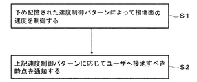
- FIG. 2 is a flowchart showing the operation of the exercise support device 1 shown in FIG. As shown in FIG. 2, in step S1, the detection unit 2 detects the user's touchdown time and takeoff time and acquires the user's movement pattern. The acquired exercise pattern is stored in the storage unit 4.
- step S2 the control unit 3 controls the speed of the ground plane in synchronization with the above motion pattern.
- the ground contact surface is set to a speed smaller than the set speed at the time of touchdown by the user, and from the touchdown time to the takeoff time according to the motion pattern acquired in step S1 and stored in the storage unit 4.
- the average speed of the ground contact surface during the period is defined as the above set speed.
- control unit 3 a specific example of this control by the control unit 3 will be described using a speed control pattern on the ground plane.
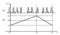
- FIG. 3A and 3B are diagrams for explaining a first specific example in speed control of a ground plane in step S2 shown in FIG. 2, respectively, FIG. 3A is a diagram showing a user's gait, and FIG. 3B is a diagram showing the user's gait.
- the horizontal axis of the waveform diagram shown in FIG. 3 (b) indicates the time t at each gait time shown in FIG. 3 (a), and the vertical axis represents the speed v of the user's ground plane at the time t. (T) is shown.
- time 0 on the horizontal axis indicates the timing at which the heel of the foot indicated by the diagonal line of the user touches the ground contact surface as shown in FIG. 3A, and at time T1, the toe of the foot touches the ground contact surface.
- the timing away from the user, time T2 indicates the timing at which the user's heel touches the ground contact surface again.
- the speed V0 on the vertical axis indicates the above-mentioned set speed
- the speed v1 indicates a speed smaller than the speed v0
- the speed v2 indicates a speed larger than the speed v0.
- FIGS. 3 (a) and 3 (b) Since the relationship between FIGS. 3 (a) and 3 (b) as described above is the same in FIGS. 4 to 6 below, duplicate description will be omitted for FIGS. 4 to 6.
- the ground plane is accelerated from speed V1 to speed V2 at a constant acceleration between time 0 and time T1. Further, from the time T1 to the time T2 thereafter, the ground plane is decelerated at a constant acceleration from the speed V2 to the speed V1.
- the floor reaction force that the user receives from the ground contact surface can be reduced as compared with the case where such acceleration is not performed.
- the floor reaction force that the user receives from the ground contact surface can be increased as compared with the case where such deceleration is not performed.
- FIG. 4A and 4B are diagrams for explaining a second specific example in speed control of the ground plane in step S2 shown in FIG. 2, respectively, FIG. 4A is a diagram showing a user's gait, and FIG. 4B is a diagram showing the user's gait.
- the acceleration of the ground plane at time 0 is maximized in the period from time 0 to time T1, and the acceleration of the ground plane at time T1 is set from time 0 to time T1.
- the speed of the ground plane is controlled so as to be the minimum in the period up to.
- FIG. 5A and 5B are diagrams for explaining a third specific example in speed control of the ground plane in step S2 shown in FIG. 2, respectively, FIG. 5A is a diagram showing a user's gait, and FIG. 5B is a diagram showing the user's gait.
- the velocity of the ground plane is controlled so that the acceleration of the ground plane at time 0 and time T1 is minimized in the period from time 0 to time T1.
- FIG. 6A and 6B are diagrams for explaining a fourth specific example in speed control of the ground plane in step S2 shown in FIG. 2, respectively, FIG. 6A is a diagram showing a user's gait, and FIG. 6B is a diagram showing the user's gait.
- the speed of the ground contact surface is controlled to be the speed v0 in the period from immediately after the user's ground contact time (time 0) to time T1.
- the algorithm as described above shown in FIG. 2 is not limited to the case of being executed by the exercise support device 1 shown in FIG. 1, and can be widely executed by using other means. In such a case. Needless to say, the same effect can be obtained.
- the user accelerates / decelerates the speed of the ground contact surface in synchronization with the user's exercise pattern. Since the magnitude of the floor reaction force received from the ground contact surface can be changed, it is easier to control the load on the body during exercise such as walking and running, such as the load on the lower limbs such as the knee, which leads to deformed knee joint disease. Can be changed by.
- FIG. 7 is a block diagram showing the configuration of the exercise support device 10 according to the second embodiment of the present invention.
- the exercise support device 10 includes an input / output unit T, a bus B connected to the input / output unit T, a notification unit 7 connected to the bus B, a control unit 3, a storage unit 4, and so on. It includes an operation unit 5 and a drive unit 6.
- the exercise support device 10 has the same configuration as the exercise support device 1 according to the first embodiment of the present invention shown in FIG. 1, the common points will be omitted, and only the differences will be described below. ..
- FIG. 8 is a flowchart showing the operation of the exercise support device 10 shown in FIG. 7.
- the control unit 3 uses the speed control pattern shown in FIGS. 3 (b) to 6 (b) stored in the storage unit 4 in advance. The speed of the ground plane is controlled.
- the notification unit 7 notifies the user of the time when the foot should be grounded on the ground contact surface according to the speed control pattern.
- the notification unit 7 is composed of, for example, a speaker or the like that notifies the user of the current time point via hearing by outputting voice at the above time point.
- the notification unit 7 may be configured by a display, a light emitting diode, or the like that visually notifies the user of the current time by outputting light or visual information at the above time. Further, the notification unit 7 may be configured by an oscillator attached to the user to notify the user of the current time point via the tactile sensation by vibrating at the above time point or outputting tactile information.
- the motion support device 10 is further provided with the detection unit 2 according to the first embodiment, and the control unit 3 is next to the user in light of the speed control pattern according to the contact time of the user detected by the detection unit 2.
- the notification unit 7 may be notified of the time when the ground should be touched.
- the notification unit 7 notifies the user of the time when the user should touch down according to the speed control pattern. As a result, it is possible to urge the user to touch down at the timing synchronized with the preset speed control pattern. Therefore, by appropriately changing the load applied to the user's lower limbs, it is possible to correct movements such as walking and running. can.
Landscapes
- Health & Medical Sciences (AREA)
- General Health & Medical Sciences (AREA)
- Physical Education & Sports Medicine (AREA)
- Cardiology (AREA)
- Vascular Medicine (AREA)
- Epidemiology (AREA)
- Pain & Pain Management (AREA)
- Rehabilitation Therapy (AREA)
- Life Sciences & Earth Sciences (AREA)
- Animal Behavior & Ethology (AREA)
- Public Health (AREA)
- Veterinary Medicine (AREA)
- Rehabilitation Tools (AREA)
Abstract
ユーザの歩行や走行といった運動時における身体への負荷を、より簡易な制御により変化させる運動支援装置及び運動支援方法を提供することを課題とする。 本課題を解決するため、ユーザが接地する面を設定速度で移動させることによりユーザの運動を支援する運動支援装置であって、ユーザの接地時点及び離地時点を検出してユーザの運動パターンを取得する検出部2と、上記運動パターンに同期して上記面の速度を制御する制御部3を備えた運動支援装置1を提供する。
Description
本発明は、ユーザの運動を支援する技術に関するものである。
これまで、ユーザが歩行訓練を行うための装置が種々考案されている。例えば、特許文献1には、設定した速度で運動するベルト状の歩行路面を備えたトレッドミルを用いた歩行訓練装置1が開示されている。なお、非特許文献1には、静止立位の状態にあるユーザの運動に同期して床を動かした場合に、当該運動が変化することが開示されている。
E. Yu, M. Abe, K. Masani, N. Kawashima, F. Eto, N. Haga, and K. Nakazawa,"Evaluation of Postural Control in Quiet Standing Using Center of Mass Acceleration: Comparison Among the Young, the Elderly, and People With Stroke",Archives of Physical Medicine and Rehabilitation, 89:1133-1139,2008
特許文献1に記載された歩行訓練装置1は、歩道手段2の変位、速度、加速度、張力を検出し、その検出結果と歩道手段2の負荷特性とに基づくフィードバック制御則によって歩道手段2を駆動するものであるため、複雑な制御が必要になるという課題がある。
本発明は、このような課題を解決するためになされたもので、ユーザの歩行や走行といった運動時における身体への負荷を、より簡易な制御により変化させる運動支援装置及び運動支援方法を提供することを目的とする。
上記課題を解決するため、本発明は、ユーザが接地する面を設定速度で移動させることによりユーザの運動を支援する運動支援装置であって、ユーザの接地時点及び離地時点を検出してユーザの運動パターンを取得する検出手段と、上記運動パターンに同期して上記面の速度を制御する制御手段を備えた運動支援装置を提供する。
また、上記課題を解決するため、本発明は、ユーザが接地する面を設定速度で移動させることによりユーザの運動を支援する運動支援装置であって、上記面の速度を制御するための速度制御パターンを記憶する記憶手段と、記憶手段に記憶された速度制御パターンによって上記面の速度を制御する制御手段と、上記速度制御パターンに応じてユーザへ接地すべき時点を通知する通知手段を備えた運動支援装置を提供する。
また、上記課題を解決するため、本発明は、ユーザが接地する面を設定速度で移動させることによりユーザの運動を支援する運動支援方法であって、ユーザの接地時点及び離地時点を検出してユーザの運動パターンを取得する第一のステップと、上記運動パターンに同期して上記面の速度を制御する第二のステップを有する運動支援方法を提供する。
また、上記課題を解決するため、本発明は、ユーザが接地する面を設定速度で移動させることによりユーザの運動を支援する運動支援方法であって、予め記憶された速度制御パターンによって上記面の速度を制御する第一のステップと、上記速度制御パターンに応じてユーザへ接地すべき時点を通知する第二のステップを有する運動支援方法を提供する。
本発明によれば、ユーザの歩行や走行といった運動時における身体への負荷を、より簡易な制御により変化させる運動支援装置及び運動支援方法を提供することができる。
[実施の形態1]
以下において、本発明の実施の形態1を、図面を参照しつつ詳しく説明する。なお、図中同一符号は同一又は相当部分を示す。
以下において、本発明の実施の形態1を、図面を参照しつつ詳しく説明する。なお、図中同一符号は同一又は相当部分を示す。
図1は、本発明の実施の形態1に係る運動支援装置1の構成を示すブロック図である。図1に示されるように、運動支援装置1は入出力部Tと、入出力部Tに接続されたバスBと、それぞれバスBに接続された検出部2、制御部3、記憶部4、操作部5、及び駆動部6を備える。
ここで、駆動部6は例えば、特許文献1の図1に示されるように、別個独立な二つの環状ベルトを用いてユーザの左右の足が接地する面を設定速度で移動させるトレッドミルにより構成される。
検出部2は例えば、上記環状ベルトの下若しくは運動支援装置1の下に設置され、ユーザと上記接地面との間の接触力を計測する床反力計により構成される。このような床反力計を用いれば、床反力の鉛直成分がある閾値を上回った時とする接地タイミングと、上記鉛直成分が上記閾値を下回った時とする離地タイミングを検出して、ユーザの運動パターンを取得することができる。
また、検出部2は、足にマーカを貼付したユーザを撮像する光学式モーションキャプチャシステムにより構成しても良い。このような光学式モーションキャプチャシステムを用いれば、撮像されたマーカの位置を計測してマーカの鉛直方向における位置がある閾値を下回った時とする接地タイミングと、上記鉛直方向の位置が上記閾値を上回った時とする離地タイミングを検出して、ユーザの運動パターンを取得することができる。
また、検出部2は、上記環状ベルトの張力を計測するベルト張力計により構成しても良い。このようなベルト張力計を用いれば、環状ベルトの張力がある閾値を上回った時とする接地タイミングと、環状ベルトの張力が上記閾値を下回った時とする離地タイミングを検出して、運動パターンを取得することができる。
制御部3は、中央演算処理装置(CPU)により構成され、検出部2により取得されたユーザの運動パターンに応じて上記環状ベルトの速度を制御するが、その制御方法については後に詳しく説明する。記憶部4は、メモリにより構成され、検出部2で取得された上記運動パターンを記憶する。操作部5は、ユーザインタフェースにより構成され、ユーザが所望する動作を実行するための命令を受け付ける。
図2は、図1に示された運動支援装置1の動作を示すフローチャートである。図2に示されるように、運動支援装置1はステップS1において、検出部2がユーザの接地時点及び離地時点を検出して当該ユーザの運動パターンを取得する。なお、取得された運動パターンは、記憶部4に記憶される。
次に、制御部3は、ステップS2において、上記運動パターンに同期して接地面の速度を制御する。本制御では例えば、ユーザの接地時点で接地面を設定速度より小さな速度とすると共に、ステップS1で取得され記憶部4に記憶された上記運動パターンに応じて、上記接地時点から離地時点までの期間における接地面の平均速度が上記設定速度とされる。
以下において、制御部3による本制御の具体例を接地面の速度制御パターンを用いて説明する。
(速度制御パターン例1)
図3は、図2に示されたステップS2における接地面の速度制御における第一の具体例を説明する図であり、それぞれ図3(a)はユーザの歩様を示す図、図3(b)は図3(a)に示された各歩様時における接地面の速度を示す波形図である。
図3は、図2に示されたステップS2における接地面の速度制御における第一の具体例を説明する図であり、それぞれ図3(a)はユーザの歩様を示す図、図3(b)は図3(a)に示された各歩様時における接地面の速度を示す波形図である。
ここで、図3(b)に示される波形図の横軸は、図3(a)に示された各歩様時における時刻tを示し、縦軸は時刻tにおけるユーザの接地面の速度v(t)を示す。そして、横軸の時刻0は図3(a)に示されるようにユーザの斜線で示された足の踵が接地面に接地するタイミングを示し、それぞれ、時刻T1は上記足のつま先が接地面から離れるタイミング、時刻T2はユーザの上記踵が再度接地面に接地するタイミングを示す。
また、縦軸の速度V0は上記設定速度を示し、速度v1は速度v0より小さい速度、速度v2は速度v0より大きい速度を示す。
なお、以上のような図3(a)と図3(b)の関係は、以下の図4から図6においても同様であるため、図4から図6については重複説明を省略する。
図3(b)に示されるように、本例では、時刻0から時刻T1までの間において、接地面は速度V1から速度V2まで一定加速度で加速される。また、その後の時刻T1から時刻T2までの間において、接地面は速度V2から速度V1まで一定加速度で減速される。
以上のように、ユーザの運動パターンに同期して接地面を加速することにより、ユーザが接地面から受ける床反力を、このような加速を行わない場合に比して低減することができるため、変形膝関節症等につながる膝等下肢へのユーザにおける負荷を低減することができる。
なお、ユーザの運動パターンに同期して接地面を減速すれば、ユーザが接地面から受ける床反力を、このような減速を行わない場合に比して増加させることができる。
以上のような接地面の加減速による作用効果は、以下の速度制御パターンによっても同様に得ることができる。
(速度制御パターン例2)
図4は、図2に示されたステップS2における接地面の速度制御における第二の具体例を説明する図であり、それぞれ図4(a)はユーザの歩様を示す図、図4(b)は図4(a)に示された各歩様時における接地面の速度を示す波形図である。
図4は、図2に示されたステップS2における接地面の速度制御における第二の具体例を説明する図であり、それぞれ図4(a)はユーザの歩様を示す図、図4(b)は図4(a)に示された各歩様時における接地面の速度を示す波形図である。
図4(b)に示されるように、本例では、時刻0における接地面の加速度を時刻0から時刻T1までの期間において最大とすると共に、時刻T1における接地面の加速度を時刻0から時刻T1までの期間において最小とするように接地面の速度が制御される。
(速度制御パターン例3)
図5は、図2に示されたステップS2における接地面の速度制御における第三の具体例を説明する図であり、それぞれ図5(a)はユーザの歩様を示す図、図5(b)は図5(a)に示された各歩様時における接地面の速度を示す波形図である。
図5は、図2に示されたステップS2における接地面の速度制御における第三の具体例を説明する図であり、それぞれ図5(a)はユーザの歩様を示す図、図5(b)は図5(a)に示された各歩様時における接地面の速度を示す波形図である。
図5(b)に示されるように、本例では、時刻0及び時刻T1における接地面の加速度が時刻0から時刻T1までの期間において最小となるように接地面の速度が制御される。
(速度制御パターン例4)
図6は、図2に示されたステップS2における接地面の速度制御における第四の具体例を説明する図であり、それぞれ図6(a)はユーザの歩様を示す図、図6(b)は図6(a)に示された各歩様時における接地面の速度を示す波形図である。
図6は、図2に示されたステップS2における接地面の速度制御における第四の具体例を説明する図であり、それぞれ図6(a)はユーザの歩様を示す図、図6(b)は図6(a)に示された各歩様時における接地面の速度を示す波形図である。
図6(b)に示されるように、本例では、接地面の速度を、ユーザの接地時点(時刻0)の直後から時刻T1までの期間において速度v0とするよう制御される。
なお、図2に示された以上のようなアルゴリズムは、図1に示された運動支援装置1によって実行する場合に限られず、広く他の手段を用いて実行することができ、このような場合にも同様な効果を得ることができることは言うまでもない。
以上より、本発明の実施の形態1に係る運動支援装置1及び図2に示された運動支援方法によれば、ユーザの運動パターンに同期して接地面の速度を加減速することにより、ユーザが接地面から受ける床反力の大きさを変化させることができるため、変形膝関節症等につながる膝等下肢への負荷など、歩行や走行といった運動時における身体への負荷をより簡易な制御により変化させることができる。
[実施の形態2]
図7は、本発明の実施の形態2に係る運動支援装置10の構成を示すブロック図である。図7に示されるように、運動支援装置10は入出力部Tと、入出力部Tに接続されたバスBと、それぞれバスBに接続された通知部7、制御部3、記憶部4、操作部5、及び駆動部6を備える。
図7は、本発明の実施の形態2に係る運動支援装置10の構成を示すブロック図である。図7に示されるように、運動支援装置10は入出力部Tと、入出力部Tに接続されたバスBと、それぞれバスBに接続された通知部7、制御部3、記憶部4、操作部5、及び駆動部6を備える。
運動支援装置10は図1に示された本発明の実施の形態1に係る運動支援装置1と同様の構成を有するため、共通点については説明を省略し、以下においては相違点についてのみ説明する。
図8は、図7に示された運動支援装置10の動作を示すフローチャートである。図8に示されるように、運動支援装置10はステップS1において、制御部3が、予め記憶部4に記憶された図3(b)から図6(b)に示される上記速度制御パターンによって、上記接地面の速度を制御する。
次に、ステップS2において、通知部7は、上記速度制御パターンに応じてユーザへ上記接地面に足を接地すべき時点を通知する。ここで、通知部7は例えば、上記時点に音声を出力することによって聴覚を介してユーザへ本時点を通知するスピーカ等により構成される。
なお、通知部7は、上記時点に光や視覚情報を出力することによって、視覚を介してユーザへ本時点を通知するディスプレイや発光ダイオード等により構成しても良い。また、通知部7は、上記時点に振動し、若しくは触覚情報を出力することによって、触覚を介してユーザへ本時点を通知するユーザに装着された振動子により構成しても良い。
また、運動支援装置10に実施の形態1に係る検出部2をさらに設け、制御部3が検出部2により検出されたユーザの接地時点に応じて、上記速度制御パターンに照らしてユーザが次に接地すべき時点を通知部7に通知させるようにしても良い。
以上より、本発明の実施の形態2に係る運動支援装置10及び図8に示された運動支援方法によれば、通知部7が速度制御パターンに応じてユーザへ接地すべき時点を通知することにより、予め設定された速度制御パターンに同期したタイミングで接地することをユーザへ促すことができるため、ユーザの下肢に与える負荷を適正に変化させることにより、歩行や走行といった運動を矯正することができる。
1,10 運動支援装置、2 検出部、3 制御部、7 通知部。
Claims (15)
- ユーザが接地する面を設定速度で移動させることにより前記ユーザの運動を支援する運動支援装置であって、
前記ユーザの接地時点及び離地時点を検出して前記ユーザの運動パターンを取得する検出手段と、
前記運動パターンに同期して前記面の速度を制御する制御手段を備えた運動支援装置。 - 前記制御手段は、前記検出手段により検出された前記接地時点において前記面を前記設定速度より小さな速度にすると共に、前記運動パターンに応じて、前記接地時点から前記離地時点までの期間における前記面の平均速度を前記設定速度とする、請求項1に記載の運動支援装置。
- 前記制御手段は、前記期間における前記面の加速度を一定とする、請求項2に記載の運動支援装置。
- 前記制御手段は、前記接地時点における前記面の加速度を前記期間において最大とすると共に、前記離地時点における前記加速度を前記期間において最小とする、請求項2に記載の運動支援装置。
- 前記制御手段は、前記接地時点及び前記離地時点における前記面の加速度を前記期間において最小とする、請求項2に記載の運動支援装置。
- 前記制御手段は、前記面の速度を前記接地時点の直後から前記期間において前記設定速度とする、請求項2に記載の運動支援装置。
- ユーザが接地する面を設定速度で移動させることにより前記ユーザの運動を支援する運動支援装置であって、
前記面の速度を制御するための速度制御パターンを記憶する記憶手段と、
前記記憶手段に記憶された前記速度制御パターンによって前記面の速度を制御する制御手段と、
前記速度制御パターンに応じて前記ユーザへ接地すべき時点を通知する通知手段を備えた運動支援装置。 - 前記速度制御パターンは、前記ユーザの前記面への接地時点における前記面の速度が前記設定速度より小さく、前記接地時点から前記ユーザの離地時点までの期間における前記面の平均速度が前記設定速度である、請求項7に記載の運動支援装置。
- 前記速度制御パターンは、前記期間における前記面の加速度が一定である、請求項8に記載の運動支援装置。
- 前記速度制御パターンは、前記接地時点における前記面の加速度が前記期間において最大であると共に、前記離地時点における前記加速度が前記期間において最小である、請求項8に記載の運動支援装置。
- 前記速度制御パターンは、前記接地時点及び前記離地時点における前記面の加速度が前記期間において最小である、請求項8に記載の運動支援装置。
- 前記速度制御パターンは、前記接地時点の直後から前記期間において前記面の速度を前記設定速度とする、請求項8に記載の運動支援装置。
- 前記ユーザの接地時点及び離地時点を検出する検出手段をさらに備え、
前記制御手段は、前記検出手段により検出された前記ユーザの接地時点に応じて、前記速度制御パターンに照らして前記ユーザが次に接地すべき時点を前記通知手段に通知させる、請求項7に記載の運動支援装置。 - ユーザが接地する面を設定速度で移動させることにより前記ユーザの運動を支援する運動支援方法であって、
前記ユーザの接地時点及び離地時点を検出して前記ユーザの運動パターンを取得する第一のステップと、
前記運動パターンに同期して前記面の速度を制御する第二のステップを有する運動支援方法。 - ユーザが接地する面を設定速度で移動させることにより前記ユーザの運動を支援する運動支援方法であって、
予め記憶された速度制御パターンによって前記面の速度を制御する第一のステップと、
前記速度制御パターンに応じて前記ユーザへ接地すべき時点を通知する第二のステップを有する運動支援方法。
Priority Applications (1)
| Application Number | Priority Date | Filing Date | Title |
|---|---|---|---|
| JP2022560738A JP7449603B2 (ja) | 2020-11-09 | 2021-10-27 | 運動支援装置及び運動支援方法 |
Applications Claiming Priority (2)
| Application Number | Priority Date | Filing Date | Title |
|---|---|---|---|
| JP2020186753 | 2020-11-09 | ||
| JP2020-186753 | 2020-11-09 |
Publications (1)
| Publication Number | Publication Date |
|---|---|
| WO2022097543A1 true WO2022097543A1 (ja) | 2022-05-12 |
Family
ID=81457784
Family Applications (1)
| Application Number | Title | Priority Date | Filing Date |
|---|---|---|---|
| PCT/JP2021/039613 Ceased WO2022097543A1 (ja) | 2020-11-09 | 2021-10-27 | 運動支援装置及び運動支援方法 |
Country Status (2)
| Country | Link |
|---|---|
| JP (1) | JP7449603B2 (ja) |
| WO (1) | WO2022097543A1 (ja) |
Cited By (1)
| Publication number | Priority date | Publication date | Assignee | Title |
|---|---|---|---|---|
| JP2025021231A (ja) * | 2023-07-31 | 2025-02-13 | 株式会社レクア | 姿勢及び歩行安定用の支援装置および支援方法 |
Citations (6)
| Publication number | Priority date | Publication date | Assignee | Title |
|---|---|---|---|---|
| JPH10243979A (ja) * | 1997-03-05 | 1998-09-14 | Hitachi Ltd | 歩行訓練装置 |
| JP2002336315A (ja) * | 2001-05-15 | 2002-11-26 | National Institute Of Advanced Industrial & Technology | 歩行訓練装置 |
| JP2005211086A (ja) * | 2004-01-27 | 2005-08-11 | Yaskawa Electric Corp | 歩行訓練装置 |
| US20100298102A1 (en) * | 2009-04-16 | 2010-11-25 | Caitlyn Joyce Bosecker | Dynamic lower limb rehabilitation robotic apparatus and method of rehabilitating human gait |
| JP2011050451A (ja) * | 2009-08-31 | 2011-03-17 | Waseda Univ | 歩行リハビリ装置 |
| JP2020137945A (ja) * | 2019-03-01 | 2020-09-03 | 国立大学法人 大分大学 | 歩行訓練システム、訓練支援装置、訓練支援方法、及び訓練支援用コンピュータプログラム |
Family Cites Families (1)
| Publication number | Priority date | Publication date | Assignee | Title |
|---|---|---|---|---|
| JP3584506B2 (ja) * | 1994-11-18 | 2004-11-04 | 株式会社日立製作所 | 歩行訓練装置及びその制御方法 |
-
2021
- 2021-10-27 WO PCT/JP2021/039613 patent/WO2022097543A1/ja not_active Ceased
- 2021-10-27 JP JP2022560738A patent/JP7449603B2/ja active Active
Patent Citations (6)
| Publication number | Priority date | Publication date | Assignee | Title |
|---|---|---|---|---|
| JPH10243979A (ja) * | 1997-03-05 | 1998-09-14 | Hitachi Ltd | 歩行訓練装置 |
| JP2002336315A (ja) * | 2001-05-15 | 2002-11-26 | National Institute Of Advanced Industrial & Technology | 歩行訓練装置 |
| JP2005211086A (ja) * | 2004-01-27 | 2005-08-11 | Yaskawa Electric Corp | 歩行訓練装置 |
| US20100298102A1 (en) * | 2009-04-16 | 2010-11-25 | Caitlyn Joyce Bosecker | Dynamic lower limb rehabilitation robotic apparatus and method of rehabilitating human gait |
| JP2011050451A (ja) * | 2009-08-31 | 2011-03-17 | Waseda Univ | 歩行リハビリ装置 |
| JP2020137945A (ja) * | 2019-03-01 | 2020-09-03 | 国立大学法人 大分大学 | 歩行訓練システム、訓練支援装置、訓練支援方法、及び訓練支援用コンピュータプログラム |
Cited By (2)
| Publication number | Priority date | Publication date | Assignee | Title |
|---|---|---|---|---|
| JP2025021231A (ja) * | 2023-07-31 | 2025-02-13 | 株式会社レクア | 姿勢及び歩行安定用の支援装置および支援方法 |
| JP7784736B2 (ja) | 2023-07-31 | 2025-12-12 | 株式会社レクア | 姿勢及び歩行安定用の支援装置 |
Also Published As
| Publication number | Publication date |
|---|---|
| JP7449603B2 (ja) | 2024-03-14 |
| JPWO2022097543A1 (ja) | 2022-05-12 |
Similar Documents
| Publication | Publication Date | Title |
|---|---|---|
| JP6399034B2 (ja) | 歩行訓練装置及びその作動方法 | |
| US8622747B2 (en) | Training system and method using a dynamic perturbation platform | |
| JP6882916B2 (ja) | 歩行支援システム、歩行支援方法、および歩行支援プログラム | |
| JP6301862B2 (ja) | 下股運動装置およびその制御方法 | |
| US20250205546A1 (en) | Treadmill arrangement with motion-adaptive virtual running environment | |
| KR102046208B1 (ko) | 보행 지원 장치 및 보행 지원 방법 | |
| CN110812131B (zh) | 外骨骼机器人的步态控制方法、控制系统及外骨骼机器人 | |
| CN112716755B (zh) | 使用可穿戴装置的平衡训练方法和可穿戴装置 | |
| KR101712918B1 (ko) | 상호작용 힘을 통한 연속보행 인식방법 및 착용형 외골격 로봇 | |
| JP7449603B2 (ja) | 運動支援装置及び運動支援方法 | |
| KR101570679B1 (ko) | 근전도 센서를 이용한 동작 추론 방법과 시스템 | |
| CN113940667A (zh) | 基于助行器的防摔倒助行方法、系统和终端设备 | |
| JP5737191B2 (ja) | 生体動作補助装置、その制御方法及び制御プログラム | |
| JP2005211086A (ja) | 歩行訓練装置 | |
| JP6665763B2 (ja) | 転倒報知システム | |
| KR101588281B1 (ko) | 재활 보조기기용 제어 시스템 | |
| KR101821592B1 (ko) | 가상 현실을 이용한 보행 시뮬레이터 시스템 및 그 보행자 위치 산출 방법 | |
| CN111312362B (zh) | 原地踏步训练方法、装置、终端及存储介质 | |
| US9849049B2 (en) | Driving apparatus and driving method | |
| JP3584506B2 (ja) | 歩行訓練装置及びその制御方法 | |
| JP2022039192A (ja) | 歩行補助装置 | |
| JP6694214B2 (ja) | 歩行支援装置 | |
| Jirattigalachote et al. | Virtual pebble: a haptic state display for pedestrians | |
| Kikuchi et al. | Gait measurement system to develop control model of intelligently controllable ankle-foot orthosis | |
| CN110430853B (zh) | 步行支援系统、步行支援方法及程序 |
Legal Events
| Date | Code | Title | Description |
|---|---|---|---|
| 121 | Ep: the epo has been informed by wipo that ep was designated in this application |
Ref document number: 21889096 Country of ref document: EP Kind code of ref document: A1 |
|
| ENP | Entry into the national phase |
Ref document number: 2022560738 Country of ref document: JP Kind code of ref document: A |
|
| NENP | Non-entry into the national phase |
Ref country code: DE |
|
| 122 | Ep: pct application non-entry in european phase |
Ref document number: 21889096 Country of ref document: EP Kind code of ref document: A1 |