WO2022097306A1 - 受信装置、受信方法、及び受信プログラム - Google Patents
受信装置、受信方法、及び受信プログラム Download PDFInfo
- Publication number
- WO2022097306A1 WO2022097306A1 PCT/JP2020/041767 JP2020041767W WO2022097306A1 WO 2022097306 A1 WO2022097306 A1 WO 2022097306A1 JP 2020041767 W JP2020041767 W JP 2020041767W WO 2022097306 A1 WO2022097306 A1 WO 2022097306A1
- Authority
- WO
- WIPO (PCT)
- Prior art keywords
- training signal
- wireless communication
- unit
- transmitted
- communication system
- Prior art date
- Legal status (The legal status is an assumption and is not a legal conclusion. Google has not performed a legal analysis and makes no representation as to the accuracy of the status listed.)
- Ceased
Links
Images



Classifications
-
- H—ELECTRICITY
- H04—ELECTRIC COMMUNICATION TECHNIQUE
- H04L—TRANSMISSION OF DIGITAL INFORMATION, e.g. TELEGRAPHIC COMMUNICATION
- H04L27/00—Modulated-carrier systems
- H04L27/18—Phase-modulated carrier systems, i.e. using phase-shift keying
-
- H—ELECTRICITY
- H04—ELECTRIC COMMUNICATION TECHNIQUE
- H04L—TRANSMISSION OF DIGITAL INFORMATION, e.g. TELEGRAPHIC COMMUNICATION
- H04L27/00—Modulated-carrier systems
- H04L27/26—Systems using multi-frequency codes
Definitions
- the present invention relates to a receiving device, a receiving method, and a receiving program.
- a technique is known in which a receiving device that performs wireless communication uses training signals that are known to each other between transmission and reception for training to know the characteristics of a propagation channel.
- Patent Document 1 discloses a technique for relieving the deterioration of the quality of a wireless line by switching the wireless line to a wireless standby line when the line quality of the wireless line deteriorates.
- some wireless maintenance tools for maintaining the quality of wireless communication estimate and display the interference wave spectrum from other systems. Then, the maintenance person of the wireless communication considers the frequency of the interference wave and proposes the optimum frequency arrangement of the desired wave.
- An object of the present invention is to provide a receiving device, a receiving method, and a receiving program capable of enabling an appropriate frequency arrangement of a desired wave even if a frequency shift occurs in an interference wave.
- the receiving device includes a storage unit that stores features of each known different training signal that can be transmitted by a plurality of different wireless communication systems, and a training signal transmitted by any of the wireless communication systems.
- the identification unit that identifies the type of the wireless communication system that transmitted the training signal based on the receiving unit that receives the training signal, the training signal received by the receiving unit, and the feature amount stored in the storage unit, and the receiving unit.
- the estimation unit Based on the training signal received by the unit and the type of the wireless communication system identified by the identification unit, the estimation unit that estimates the transmission frequency of the wireless communication system that transmitted the training signal and the transmission frequency estimated by the estimation unit are used. It is characterized by having an output unit for outputting the indicated information.
- the receiving method includes a receiving step of receiving a training signal transmitted by a wireless communication system, a received training signal, and a known different training signal that can be transmitted by a plurality of different wireless communication systems.
- the identification step of identifying the type of wireless communication system that transmitted the training signal based on the feature quantity of, and the wireless communication system that transmitted the training signal based on the received training signal and the type of the identified wireless communication system. It is characterized by including an estimation step of estimating the transmission frequency of the above and an output step of outputting information indicating the estimated transmission frequency.
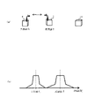
- FIG. 1 It is a functional block diagram illustrating the function which the receiving apparatus which concerns on one Embodiment has.
- A is a figure which showed the interference wave measured by the measuring part as a spectrum.
- B is a diagram illustrating the frequency distribution of the interference wave measured by the measuring unit.
- C is a diagram illustrating the frequency of the interference wave estimated by the receiving device and the frequency of the desired wave. It is a figure which shows the hardware configuration example of the receiving apparatus which concerns on one Embodiment.
- A is a diagram illustrating an environment for estimating an interference wave in normal wireless communication.
- B is a figure which shows the display example of the arrangement of the interference wave and the desired wave in the wireless communication in a normal time.
- (A) is a diagram illustrating an environment for estimating an interference wave in wireless communication when the frequency of the interference wave fluctuates.
- (B) is a figure which shows the display example of the arrangement of the interference wave and the desired wave in the radio communication when the frequency of the interference wave fluctuates.
- FIG. 4 is a diagram illustrating estimation and display of interference waves in normal wireless communication.
- FIG. 4A is a diagram illustrating an environment for estimating an interference wave in normal wireless communication.
- FIG. 4B is a diagram showing a display example of the arrangement of interference waves and desired waves in normal wireless communication.
- another wireless communication system that transmits an interference wave of frequency f1 is surrounded by a wireless communication system (transmitter) 1 that transmits a desired wave of frequency f. 2 exists.
- the wireless communication system 1 and the wireless communication system 2 each transmit known training signals to perform wireless communication.
- the receiving device 10 of the comparative example receives a known training signal transmitted by the wireless communication system 1 and the wireless communication system 2, respectively, and interferes with a desired wave transmitted by the wireless communication system 1 and transmitted by the wireless communication system 2. It is a maintenance tool for wireless communication that estimates and displays the wave spectrum. For example, the receiving device 10 displays a desired wave and an interference wave as shown in FIG. 4 (b).
- the maintenance person of the wireless communication can determine the frequency arrangement of the desired wave as displayed by the receiving device 10 to maintain the communication quality. It is possible.
- FIG. 5 is a diagram illustrating the estimation and display of the interference wave in wireless communication when the frequency of the interference wave fluctuates.
- FIG. 5A is a diagram illustrating an environment for estimating an interference wave in wireless communication when the frequency of the interference wave fluctuates.
- FIG. 5B is a diagram showing a display example of the arrangement of the interference wave and the desired wave in wireless communication when the frequency of the interference wave fluctuates.
- the configurations substantially the same as those shown in FIG. 4 are designated by the same reference numerals.
- the interference wave of frequency f1 transmitted by the wireless communication system 2 is received by the receiving device 10 via the propagation path reflected by the moving body 100 such as a vehicle. In some cases.
- the receiving device 10 when the receiving device 10 receives a radio wave having a Doppler effect on an interference wave having a frequency f 1 transmitted by the wireless communication system 2, the frequency of the interference wave received by the receiving device 10 is f 1 + ⁇ f (or It may fluctuate to f1 ⁇ f ) or the like, and may be different from the interference wave having the frequency f1 transmitted by the wireless communication system 2 .
- the frequency of the interference wave received by the receiving device 10 is f 1 + ⁇ f (or f 1 ⁇ ⁇ f). And so on.
- the receiving device 10 displays an interference wave having a frequency (f 1 + ⁇ f, etc.) different from the interference wave having a frequency f 1 transmitted by the wireless communication system 2. That is, the maintenance person cannot correctly know the frequency f1 of the interference wave transmitted by the wireless communication system 2 .
- the frequency of the interference wave received by the receiving device 10 fluctuates (shifts) so as to approach the frequency of the desired wave, it is desired to separate the desired wave from the interference wave of the fluctuating frequency in order to prevent interference. It becomes necessary to change the frequency arrangement of the wave, and the frequency utilization efficiency is reduced.
- the receiving device 3 is configured to enable an appropriate frequency arrangement of the desired wave even if the interference wave has a frequency shift.
- FIG. 1 is a functional block diagram illustrating the functions of the receiving device 3 according to the embodiment.
- the receiving device 3 has a storage unit 30, a receiving unit 31, a measuring unit 32, an identification unit 33, an estimation unit 34, a calculation unit 35, and a display unit 36.
- the storage unit 30 is a database that stores the feature amounts of each of the known different training signals that can be transmitted by a plurality of different wireless communication systems (transmitters) such as the wireless communication system 1 and the wireless communication system 2.
- the feature amount of the training signal also includes the frequency band and bandwidth of the training signal.
- the storage unit 30 may store the information used by the estimation unit 34 and the calculation unit 35, which will be described later.
- the storage unit 30 stores the carrier frequency offset (for example, 0.3 ppm as the upper limit of the radio equipment rule), the learning data for the Doppler effect, the past history of the frequency shift distribution, the pattern of the spectral distortion due to the frequency shift, and the like. May be.
- the receiving unit 31 receives training signals transmitted by a plurality of different wireless communication systems (transmitting devices) such as the wireless communication system 1 and the wireless communication system 2 via the antenna, and processes the received signals, for example, in a later stage. It is converted into a possible signal and output to the measuring unit 32.
- a plurality of different wireless communication systems such as the wireless communication system 1 and the wireless communication system 2 via the antenna
- the measuring unit 32 measures the training signal received by the receiving unit 31 and outputs the measurement result to the identification unit 33 and the estimation unit 34. For example, the measuring unit 32 outputs the reception level, frequency distribution, etc. of the training signal as the measurement result of the training signal received by the receiving unit 31. At this time, the measuring unit 32 estimates the frequency of the training signal, for example.
- the identification unit 33 identifies and identifies the type of wireless communication system (transmitter) that has transmitted the training signal based on the training signal measured by the measurement unit 32 and the feature amount stored in the storage unit 30. Information indicating the type of the communication system is output to the estimation unit 34. For example, the identification unit 33 identifies the type of wireless communication system that transmitted the training signal based on at least one of the frequency band and bandwidth of the training signal measured by the measurement unit 32.
- the estimation unit 34 has, for example, a CFO determination unit 340 and a Doppler determination unit 342.
- the CFO determination unit 340 determines whether or not a carrier frequency offset shift exists with respect to the frequency distribution of the training signal measured by the measurement unit 32.
- the Doppler determination unit 342 determines whether or not the Doppler effect is generated with respect to the frequency distribution of the training signal measured by the measurement unit 32.
- the Doppler determination unit 342 may learn the feature that when the Doppler effect occurs, it concentrates in a short time and a large ⁇ f is generated, and determines whether or not the Doppler effect is generated.
- the estimation unit 34 calculates, for example, the average value of the frequency distribution based on the training signal measured by the measurement unit 32 and the type of the wireless communication system identified by the identification unit 33, and transmits the training signal.
- the transmission frequency of the communication system is estimated, and the estimated transmission frequency of the wireless communication system is output to the calculation unit 35.
- the estimation unit 34 determines at least one of whether or not a carrier frequency offset shift exists and whether or not a Doppler effect occurs with respect to the frequency distribution of the training signal measured by the measurement unit 32. Based on the determination result, the transmission frequency of the wireless communication system that transmitted the training signal is estimated.
- the calculation unit 35 calculates the spectrum of the training signal transmitted by each wireless communication system based on the transmission frequency of each wireless communication system estimated by the estimation unit 34, and outputs each of the calculated spectra to the display unit 36. ..
- the display unit 36 displays each spectrum calculated by the calculation unit 35. That is, the display unit 36 has a function as an output unit that outputs information indicating the transmission frequency of the wireless communication system estimated by the estimation unit 34.
- FIG. 2 is a diagram illustrating a process in which the receiving device 3 estimates the frequency of the interference wave.
- FIG. 2A is a diagram showing the interference wave measured by the measuring unit 32 as a spectrum.
- FIG. 2B is a diagram illustrating the frequency distribution of the interference wave measured by the measuring unit 32.
- FIG. 2C is a diagram illustrating the frequency of the interference wave estimated by the receiving device 3 and the frequency of the desired wave.
- the receiving device 3 receives an interference wave in which the receiving unit 31 receives, for example, an interference wave having a bandwidth of 15 kHz in the 60 MHz band.
- the frequency of the interference wave measured by the measuring unit 32 deviates from the frequency f1 of the training signal transmitted by the wireless communication system 2 (see FIG. 5) by + ⁇ f.
- the identification unit 33 identifies the type of wireless communication system (transmitter) that has transmitted the training signal based on the feature quantities of the training signal measured by the measurement unit 32 and the training signal stored in the storage unit 30. ..
- the identification unit 33 determines that the type of the radio communication system 2 that transmits the interference wave training signal is the disaster prevention radio because the frequency band of the interference wave training signal is 60 MHz and the bandwidth is 15 kHz. decide.
- the estimation unit 34 determines that the interference wave training signal is a disaster prevention radio based on the frequency distribution of the interference wave training signal output by the measurement unit 32 as a measurement result and the identification unit 33 of the interference wave.
- the transmission frequency of the wireless communication system 2 that has transmitted the training signal is estimated (see FIG. 2B).
- the estimation unit 34 may estimate the transmission frequency of the wireless communication system 2 that has transmitted the training signal of the interference wave by performing pattern matching and learning of the spectrum distortion due to the frequency shift.
- the display unit 36 accurately corrects the spectrum of the interference wave training signal transmitted by the wireless communication system 2 even if the frequency of the interference wave training signal received by the reception unit 31 is deviated (even if it fluctuates). Display well.
- the receiving device 3 can correct and display the spectrum of the training signal of the interference wave. Therefore, the maintenance person can appropriately arrange the frequency of the desired wave by referring to the spectrum of the training signal of the corrected interference wave.
- the receiving device 3 can accurately display the spectrum of the training signal of the interference wave even if the frequency of the training signal of the received interference wave fluctuates due to the Doppler effect, CFO deviation, or the like.
- the maintenance person can perform an appropriate frequency arrangement of the desired wave even if the interference wave has a frequency shift, and can improve the frequency utilization efficiency.
- the receiving device 3 is not only used as a maintenance tool, but may also have a function of indicating an appropriate position of a desired wave frequency, or may have a function of transmitting and receiving a desired wave at an appropriate frequency. ..
- each function of the receiving device 3 may be partially or wholly configured by hardware such as PLD (Programmable Logic Device) or FPGA (Field Programmable Gate Array), or may be executed by a processor such as a CPU. It may be configured as a program.
- hardware such as PLD (Programmable Logic Device) or FPGA (Field Programmable Gate Array)
- FPGA Field Programmable Gate Array
- the receiving device 3 can be realized by using a computer and a program, and the program can be recorded on a storage medium or provided through a network.
- FIG. 3 is a diagram showing a hardware configuration example of the receiving device 3 according to the embodiment.
- the receiving device 3 has an input unit 500, an output unit 510, a communication unit 520, a CPU 530, a memory 540, and an HDD 550 connected via a bus 560, and has a function as a computer. Further, the receiving device 3 is configured to be able to input / output data to / from a computer-readable storage medium 570.
- the input unit 500 is, for example, a keyboard, a mouse, or the like.
- the output unit 510 may be the above-mentioned display unit 36 such as a display, or may have a function of outputting the processing result as another signal.
- the communication unit 520 is, for example, a network interface, and includes, for example, the reception unit 31 described above.
- the CPU 530 controls each part constituting the receiving device 3 and performs predetermined processing and the like.
- the memory 540 and the HDD 550 constitute, for example, the above-mentioned storage unit 30 for storing data and the like.
- the storage medium 570 is capable of storing a program or the like for executing the function of the receiving device 3.
- the architecture constituting the receiving device 3 is not limited to the example shown in FIG.
Landscapes
- Engineering & Computer Science (AREA)
- Computer Networks & Wireless Communication (AREA)
- Signal Processing (AREA)
- Monitoring And Testing Of Transmission In General (AREA)
Abstract
一実施形態にかかる受信装置は、複数の異なる無線通信システムが送信し得る既知の異なるトレーニング信号それぞれの特徴量を記憶している記憶部と、無線通信システムのいずれかが送信したトレーニング信号を受信する受信部と、受信部が受信したトレーニング信号、及び記憶部が記憶している特徴量に基づいて、トレーニング信号を送信した無線通信システムの種類を同定する同定部と、受信部が受信したトレーニング信号、及び同定部が同定した無線通信システムの種類に基づいて、トレーニング信号を送信した無線通信システムの送信周波数を推定する推定部と、推定部が推定した送信周波数を示す情報を出力する出力部とを有することを特徴とする。
Description
本発明は、受信装置、受信方法、及び受信プログラムに関する。
従来、無線通信を行う受信装置が伝搬チャネルの特性を知るトレーニングのために、送受信間で互いに既知のトレーニング信号を用いる技術が知られている。
無線通信の品質は、干渉波などの通信環境によって変動する。例えば、特許文献1には、無線回線の回線品質が劣化した場合に、その無線回線を無線予備回線へ切替えることにより無線回線の品質劣化を救済する技術が開示されている。
また、無線通信の品質を保つための無線保守ツールには、他のシステムからの干渉波スペクトラムを推定して表示するものがある。そして、無線通信の保守者は、干渉波の周波数を考慮して、所望波の最適な周波数配置の提案等を行う。
しかしながら、従来の無線保守ツールでは、動的環境によってドップラー効果が生じたり、他システムの無線局にキャリア周波数オフセット(CFO:搬送周波数オフセット)ずれが存在する場合、干渉波の周波数を正しく推定することができなかった。
この場合、所望波に対して干渉波が干渉することを防止するためには、所望波の周波数を過度にずらして配置しなければならないことがあり、周波数の利用効率が低下してしまうという問題があった。
本発明は、干渉波に周波数ずれが生じていても、所望波の適正な周波数配置を可能にすることができる受信装置、受信方法、及び受信プログラムを提供することを目的とする。
本発明の一態様にかかる受信装置は、複数の異なる無線通信システムが送信し得る既知の異なるトレーニング信号それぞれの特徴量を記憶している記憶部と、無線通信システムのいずれかが送信したトレーニング信号を受信する受信部と、前記受信部が受信したトレーニング信号、及び前記記憶部が記憶している特徴量に基づいて、トレーニング信号を送信した無線通信システムの種類を同定する同定部と、前記受信部が受信したトレーニング信号、及び前記同定部が同定した無線通信システムの種類に基づいて、トレーニング信号を送信した無線通信システムの送信周波数を推定する推定部と、前記推定部が推定した送信周波数を示す情報を出力する出力部とを有することを特徴とする。
また、本発明の一態様にかかる受信方法は、無線通信システムが送信したトレーニング信号を受信する受信工程と、受信したトレーニング信号と、複数の異なる無線通信システムが送信し得る既知の異なるトレーニング信号それぞれの特徴量とに基づいて、トレーニング信号を送信した無線通信システムの種類を同定する同定工程と、受信したトレーニング信号、及び同定した無線通信システムの種類に基づいて、トレーニング信号を送信した無線通信システムの送信周波数を推定する推定工程と、推定した送信周波数を示す情報を出力する出力工程とを含むことを特徴とする。
本発明によれば、干渉波に周波数ずれが生じていても、所望波の適正な周波数配置を可能にすることができる。
まず、本発明がなされるに至った背景について説明する。図4は、通常時の無線通信における干渉波の推定と表示を例示する図である。図4(a)は、通常時の無線通信における干渉波を推定する環境を例示する図である。図4(b)は、通常時の無線通信における干渉波と所望波の配置の表示例を示す図である。
図4(a)に示すように、例えば周波数fの所望波を送信する無線通信システム(送信装置)1の周囲には、周波数f1の干渉波を送信する他の無線通信システム(送信装置)2が存在している。無線通信システム1及び無線通信システム2は、それぞれ既知のトレーニング信号を送信して無線通信を行う。
例えば、比較例の受信装置10は、無線通信システム1及び無線通信システム2がそれぞれ送信する既知のトレーニング信号を受信し、無線通信システム1が送信する所望波と、無線通信システム2が送信する干渉波のスペクトラムを推定して表示する無線通信の保守ツールである。例えば、受信装置10は、図4(b)に示したように所望波と干渉波を表示する。
この場合、無線通信の保守者は、所望波に対して干渉波が干渉していないので、所望波の周波数配置を受信装置10が表示している通りに決定して、通信品質を保つことが可能である。
図5は、干渉波の周波数が変動している場合の無線通信における干渉波の推定と表示を例示する図である。図5(a)は、干渉波の周波数が変動している場合の無線通信における干渉波を推定する環境を例示する図である。図5(b)は、干渉波の周波数が変動している場合の無線通信における干渉波と所望波の配置の表示例を示す図である。なお、図5において、図4に示した構成と実質的に同一の構成には同一の符号が付してある。
図5(a)に示したように、無線通信システム2が送信する周波数f1の干渉波は、例えば車両などの移動体100によって反射される伝搬路を介して、受信装置10により受信される場合がある。
例えば、無線通信システム2が送信する周波数f1の干渉波に対してドップラー効果が生じた電波を受信装置10が受信する場合、受信装置10が受信する干渉波の周波数は、f1+Δf(又はf1-Δf)等に変動し、無線通信システム2が送信した周波数f1の干渉波とは異なってしまうことがある。
また、無線通信システム2が送信する電波において、キャリア周波数オフセット(CFO)ずれが存在している場合にも、受信装置10が受信する干渉波の周波数は、f1+Δf(又はf1-Δf)等に変動する。
この場合、受信装置10は、例えば図5(b)に示したように、無線通信システム2が送信した周波数f1の干渉波とは異なる周波数(f1+Δf等)の干渉波を表示する。つまり、保守者は、無線通信システム2が送信した干渉波の周波数f1を正しく知ることができない。
したがって、受信装置10が受信する干渉波の周波数が所望波の周波数に近づくように変動した場合(ずれた場合)、干渉防止のために、変動した周波数の干渉波から所望波を離すように所望波の周波数配置を変える必要が生じ、周波数の利用効率が低下してしまう。
そこで、一実施形態にかかる受信装置3は、干渉波に周波数ずれが生じていても、所望波の適正な周波数配置を可能にすることができるように構成されている。
図1は、一実施形態にかかる受信装置3が有する機能を例示する機能ブロック図である。図1に示すように、受信装置3は、記憶部30、受信部31、測定部32、同定部33、推定部34、算出部35、及び表示部36を有する。
記憶部30は、例えば無線通信システム1及び無線通信システム2などの複数の異なる無線通信システム(送信装置)が送信し得る既知の異なるトレーニング信号それぞれの特徴量等を記憶しているデータベースである。なお、トレーニング信号の特徴量には、トレーニング信号の周波数帯及び帯域幅なども含まれる。
また、記憶部30は、後述する推定部34及び算出部35が用いる情報を記憶していてもよい。例えば、記憶部30は、キャリア周波数オフセット(無線設備規則の上限として、例えば0.3ppm)、ドップラー効果に対する学習データ、及び周波数ずれ分布の過去履歴、及び周波数ずれによるスペクトル歪みのパターンなどを記憶していてもよい。
受信部31は、アンテナを介して、例えば無線通信システム1及び無線通信システム2などの複数の異なる無線通信システム(送信装置)が送信したトレーニング信号をそれぞれ受信し、受信した信号を例えば後段で処理可能な信号に変換し、測定部32に対して出力する。
測定部32は、受信部31が受信したトレーニング信号を測定し、測定結果を同定部33及び推定部34に対して出力する。例えば、測定部32は、受信部31が受信したトレーニング信号の測定結果として、トレーニング信号の受信レベルや周波数分布等を出力する。このとき、測定部32は、例えばトレーニング信号の周波数を推定する。
同定部33は、測定部32が測定したトレーニング信号、及び記憶部30が記憶している特徴量に基づいて、トレーニング信号を送信した無線通信システム(送信装置)の種類を同定し、同定した無線通信システムの種類を示す情報を推定部34に対して出力する。例えば、同定部33は、測定部32が測定したトレーニング信号の周波数帯及び帯域幅の少なくともいずれかに基づいて、トレーニング信号を送信した無線通信システムの種類を同定する。
推定部34は、例えばCFO判定部340及びドップラー判定部342を有する。CFO判定部340は、測定部32が測定したトレーニング信号の周波数分布に対し、キャリア周波数オフセットずれが存在しているか否かを判定する。また、ドップラー判定部342は、測定部32が測定したトレーニング信号の周波数分布に対し、ドップラー効果が生じているか否かを判定する。例えば、ドップラー判定部342は、ドップラー効果が生じる場合には短時間に集中して△fが大きく発生するという特徴を学習して、ドップラー効果が生じているか否かを判定してもよい。
そして、推定部34は、測定部32が測定したトレーニング信号、及び同定部33が同定した無線通信システムの種類に基づいて、例えば周波数分布の平均値等を算出して、トレーニング信号を送信した無線通信システムの送信周波数を推定し、推定した無線通信システムの送信周波数を算出部35に対して出力する。
例えば、推定部34は、測定部32が測定したトレーニング信号の周波数分布に対し、キャリア周波数オフセットずれが存在しているか否か、及びドップラー効果が生じているか否かの少なくともいずれかを判定し、判定した結果に基づいて、トレーニング信号を送信した無線通信システムの送信周波数を推定する。
算出部35は、推定部34が推定した無線通信システムそれぞれの送信周波数に基づいて、無線通信システムそれぞれが送信したトレーニング信号のスペクトラムを算出し、算出したスペクトラムそれぞれを表示部36に対して出力する。
表示部36は、算出部35が算出したスペクトラムそれぞれを表示する。つまり、表示部36は、推定部34が推定した無線通信システムの送信周波数を示す情報を出力する出力部としての機能を備える。
次に、受信装置3の具体的な動作例について、図1,2を用いて説明する。図2は、受信装置3が干渉波の周波数を推定する場合の過程を例示する図である。図2(a)は、測定部32が測定した干渉波をスペクトラムとして示した図である。図2(b)は、測定部32が測定した干渉波の周波数分布を例示する図である。図2(c)は、受信装置3が推定した干渉波の周波数と、希望波の周波数とを例示する図である。
図2(a)に示したように、受信装置3は、受信部31が例えば60MHz帯の帯域幅が15kHzである干渉波を受信する。このとき、測定部32が測定した干渉波の周波数は、無線通信システム2(図5参照)が送信したトレーニング信号の周波数f1に対して+△fだけずれている。
同定部33は、測定部32が測定したトレーニング信号、及び記憶部30が記憶しているトレーニング信号それぞれの特徴量に基づいて、トレーニング信号を送信した無線通信システム(送信装置)の種類を同定する。
例えば、同定部33は、干渉波のトレーニング信号の周波数帯が60MHz帯であり、帯域幅が15kHzであることから、干渉波のトレーニング信号を送信した無線通信システム2の種類が防災無線であると決定する。
推定部34は、測定部32が測定結果として出力した干渉波のトレーニング信号の周波数分布と、干渉波のトレーニング信号が防災無線であると同定部33が同定したこととに基づいて、干渉波のトレーニング信号を送信した無線通信システム2の送信周波数を推定する(図2(b)参照)。
また、推定部34は、周波数ずれによるスペクトラム歪みのパターンマッチング及び学習を行って、干渉波のトレーニング信号を送信した無線通信システム2の送信周波数を推定してもよい。
その結果、表示部36は、受信部31が受信した干渉波のトレーニング信号の周波数がずれていても(変動していても)、無線通信システム2が送信した干渉波のトレーニング信号のスペクトラムを精度よく表示する。
つまり、受信装置3は、干渉波のトレーニング信号のスペクトラムを補正して表示することができる。そのため、保守者は、補正後の干渉波のトレーニング信号のスペクトラムを参照して、所望波の周波数を適正に配置することができる。
このように、受信装置3は、受信した干渉波のトレーニング信号がドップラー効果やCFOずれなどによって周波数変動していても、干渉波のトレーニング信号のスペクトラムを精度よく表示することができる。
したがって、保守者は、干渉波に周波数ずれが生じていても、所望波の適正な周波数配置を行うことができ、周波数の利用効率を向上させることができる。
また、受信装置3は、保守ツールとして用いられるだけでなく、所望波の周波数の適正位置を示す機能を備えていてもよいし、適正な周波数で所望波を送受信する機能を備えていてもよい。
なお、受信装置3が有する各機能は、それぞれ一部又は全部がPLD(Programmable Logic Device)やFPGA(Field Programmable Gate Array)等のハードウェアによって構成されてもよいし、CPU等のプロセッサが実行するプログラムとして構成されてもよい。
また、本発明にかかる受信装置3は、コンピュータとプログラムを用いて実現することができ、プログラムを記憶媒体に記録することも、ネットワークを通して提供することも可能である。
図3は、一実施形態にかかる受信装置3のハードウェア構成例を示す図である。図3に示すように、例えば受信装置3は、入力部500、出力部510、通信部520、CPU530、メモリ540及びHDD550がバス560を介して接続され、コンピュータとしての機能を備える。また、受信装置3は、コンピュータ読み取り可能な記憶媒体570との間でデータを入出力することができるようにされている。
入力部500は、例えばキーボード及びマウス等である。出力部510は、例えばディスプレイなどの上述した表示部36であってもよいし、処理結果を他の信号として出力する機能を備えていてもよい。通信部520は、例えばネットワークインターフェースであり、例えば上述した受信部31を含む。
CPU530は、受信装置3を構成する各部を制御し、所定の処理等を行う。メモリ540及びHDD550は、データ等を記憶する例えば上述した記憶部30を構成する。
記憶媒体570は、受信装置3が有する機能を実行させるプログラム等を記憶可能にされている。なお、受信装置3を構成するアーキテクチャは図3に示した例に限定されない。
以上、図面を参照して本発明の実施形態を説明してきたが、上述の実施形態は、本発明の例示に過ぎず、本発明が上述の実施形態に限定されるものではないことは明らかである。したがって、本発明の技術思想及び範囲を逸脱しない範囲で、構成要素の追加、省略、置換、その他の変更が行われてもよい。
1,2・・・無線通信システム、3・・・受信装置、30・・・記憶部、31・・・受信部、32・・・測定部、33・・・同定部、34・・・推定部、35・・・算出部、36・・・表示部、100・・・移動体、500・・・入力部、510・・・出力部、520・・・通信部、530・・・CPU、540・・・メモリ、550・・・HDD、560・・・バス、570・・・記憶媒体
Claims (8)
- 複数の異なる無線通信システムが送信し得る既知の異なるトレーニング信号それぞれの特徴量を記憶している記憶部と、
無線通信システムのいずれかが送信したトレーニング信号を受信する受信部と、
前記受信部が受信したトレーニング信号、及び前記記憶部が記憶している特徴量に基づいて、トレーニング信号を送信した無線通信システムの種類を同定する同定部と、
前記受信部が受信したトレーニング信号、及び前記同定部が同定した無線通信システムの種類に基づいて、トレーニング信号を送信した無線通信システムの送信周波数を推定する推定部と、
前記推定部が推定した送信周波数を示す情報を出力する出力部と
を有することを特徴とする受信装置。 - 前記同定部は、
前記受信部が受信したトレーニング信号の周波数帯及び帯域幅の少なくともいずれかに基づいて、トレーニング信号を送信した無線通信システムの種類を同定すること
を特徴とする請求項1に記載の受信装置。 - 前記推定部は、
前記受信部が受信したトレーニング信号の周波数分布に基づいて、トレーニング信号を送信した無線通信システムの送信周波数を推定すること
を特徴とする請求項1又は2に記載の受信装置。 - 前記推定部は、
前記受信部が受信したトレーニング信号に対し、キャリア周波数オフセットずれが存在しているか否か、及びドップラー効果が生じているか否かの少なくともいずれかを判定した結果に基づいて、トレーニング信号を送信した無線通信システムの送信周波数を推定すること
を特徴とする請求項3に記載の受信装置。 - 無線通信システムが送信したトレーニング信号を受信する受信工程と、
受信したトレーニング信号と、複数の異なる無線通信システムが送信し得る既知の異なるトレーニング信号それぞれの特徴量とに基づいて、トレーニング信号を送信した無線通信システムの種類を同定する同定工程と、
受信したトレーニング信号、及び同定した無線通信システムの種類に基づいて、トレーニング信号を送信した無線通信システムの送信周波数を推定する推定工程と、
推定した送信周波数を示す情報を出力する出力工程と
を含むことを特徴とする受信方法。 - 前記同定工程では、
受信したトレーニング信号の周波数帯及び帯域幅の少なくともいずれかに基づいて、トレーニング信号を送信した無線通信システムの種類を同定すること
を特徴とする請求項5に記載の受信方法。 - 前記推定工程では、
受信したトレーニング信号の周波数分布に基づいて、トレーニング信号を送信した無線通信システムの送信周波数を推定すること
を特徴とする請求項5又は6に記載の受信方法。 - 請求項1~4のいずれか1項に記載の受信装置の各部としてコンピュータを機能させるための受信プログラム。
Priority Applications (2)
| Application Number | Priority Date | Filing Date | Title |
|---|---|---|---|
| JP2022560629A JP7487791B2 (ja) | 2020-11-09 | 2020-11-09 | 受信装置、受信方法、及び受信プログラム |
| PCT/JP2020/041767 WO2022097306A1 (ja) | 2020-11-09 | 2020-11-09 | 受信装置、受信方法、及び受信プログラム |
Applications Claiming Priority (1)
| Application Number | Priority Date | Filing Date | Title |
|---|---|---|---|
| PCT/JP2020/041767 WO2022097306A1 (ja) | 2020-11-09 | 2020-11-09 | 受信装置、受信方法、及び受信プログラム |
Publications (1)
| Publication Number | Publication Date |
|---|---|
| WO2022097306A1 true WO2022097306A1 (ja) | 2022-05-12 |
Family
ID=81457710
Family Applications (1)
| Application Number | Title | Priority Date | Filing Date |
|---|---|---|---|
| PCT/JP2020/041767 Ceased WO2022097306A1 (ja) | 2020-11-09 | 2020-11-09 | 受信装置、受信方法、及び受信プログラム |
Country Status (2)
| Country | Link |
|---|---|
| JP (1) | JP7487791B2 (ja) |
| WO (1) | WO2022097306A1 (ja) |
Citations (2)
| Publication number | Priority date | Publication date | Assignee | Title |
|---|---|---|---|---|
| JP2009118453A (ja) * | 2007-11-06 | 2009-05-28 | Samsung Electronics Co Ltd | パイロット信号を用いた周波数スペクトラムのセンシング方法およびこの方法を採用する認知無線システム |
| WO2009145326A1 (ja) * | 2008-05-27 | 2009-12-03 | 日本電気株式会社 | コグニティブ無線システム、コグニティブ無線機および無線信号検出方法 |
-
2020
- 2020-11-09 JP JP2022560629A patent/JP7487791B2/ja active Active
- 2020-11-09 WO PCT/JP2020/041767 patent/WO2022097306A1/ja not_active Ceased
Patent Citations (2)
| Publication number | Priority date | Publication date | Assignee | Title |
|---|---|---|---|---|
| JP2009118453A (ja) * | 2007-11-06 | 2009-05-28 | Samsung Electronics Co Ltd | パイロット信号を用いた周波数スペクトラムのセンシング方法およびこの方法を採用する認知無線システム |
| WO2009145326A1 (ja) * | 2008-05-27 | 2009-12-03 | 日本電気株式会社 | コグニティブ無線システム、コグニティブ無線機および無線信号検出方法 |
Also Published As
| Publication number | Publication date |
|---|---|
| JP7487791B2 (ja) | 2024-05-21 |
| JPWO2022097306A1 (ja) | 2022-05-12 |
Similar Documents
| Publication | Publication Date | Title |
|---|---|---|
| US6928274B2 (en) | Receiver device for a mobile radiocommunication unit employing a speed estimator | |
| US9810766B2 (en) | Method and apparatus for modeling time relationships between clocks | |
| JP5699545B2 (ja) | 電波伝搬特性推定システム、電波伝搬特性推定方法、およびコンピュータプログラム | |
| US8380150B2 (en) | Received electric field intensity estimating device and received electric field intensity estimating program | |
| US9445375B2 (en) | Method and system for updating predistortion coefficient | |
| JP5699544B2 (ja) | 電波伝搬特性推定システム、電波伝搬特性推定方法、およびコンピュータプログラム | |
| JP2009008452A (ja) | 広帯域レーダ装置 | |
| CN110620605B (zh) | 一种阵列天线收校准的检测方法及装置 | |
| US10560142B2 (en) | Spectral analysis apparatus and spectral analysis method | |
| US10895895B2 (en) | Electronic apparatus, measurement apparatus, and method | |
| WO2016152030A1 (ja) | 測位方法、測位システム、補正情報生成方法、補正情報生成装置、および測位システムにおける中継局、端末 | |
| EP1523113A1 (en) | Failure detecting device | |
| US10859671B2 (en) | Position estimation apparatus and position estimation method | |
| JP2923904B2 (ja) | Dgps | |
| JP7487791B2 (ja) | 受信装置、受信方法、及び受信プログラム | |
| JP2011211514A (ja) | 故障予測装置、故障予測方法、電磁干渉検出装置、電磁干渉検出方法、及び制御プログラム | |
| US10859615B2 (en) | Method and apparatus for VSWR estimation using cross-correlation and real sampling without the need for time alignment | |
| US10306497B2 (en) | Method for determining stability of a wireless signal and system thereof | |
| US20240244542A1 (en) | Method of detecting synchronization timing and sub-band based on adaptive threshold and receiver performing the same | |
| US8422960B2 (en) | Wireless communication apparatus and wireless communication method | |
| KR102132896B1 (ko) | Jtdls 항재밍 단말의 간섭신호 제거 장치 및 그 방법 | |
| US10939245B2 (en) | Position estimation system | |
| KR101905434B1 (ko) | 수동상호변조왜곡 신호 측정 장치 및 방법 | |
| US12114282B2 (en) | Electronic apparatus, electronic system, and method | |
| US20180102841A1 (en) | System performance prediction method and apparatus |
Legal Events
| Date | Code | Title | Description |
|---|---|---|---|
| 121 | Ep: the epo has been informed by wipo that ep was designated in this application |
Ref document number: 20960858 Country of ref document: EP Kind code of ref document: A1 |
|
| ENP | Entry into the national phase |
Ref document number: 2022560629 Country of ref document: JP Kind code of ref document: A |
|
| NENP | Non-entry into the national phase |
Ref country code: DE |
|
| 122 | Ep: pct application non-entry in european phase |
Ref document number: 20960858 Country of ref document: EP Kind code of ref document: A1 |