WO2022097192A1 - 高周波アンテナ測定システム - Google Patents
高周波アンテナ測定システム Download PDFInfo
- Publication number
- WO2022097192A1 WO2022097192A1 PCT/JP2020/041168 JP2020041168W WO2022097192A1 WO 2022097192 A1 WO2022097192 A1 WO 2022097192A1 JP 2020041168 W JP2020041168 W JP 2020041168W WO 2022097192 A1 WO2022097192 A1 WO 2022097192A1
- Authority
- WO
- WIPO (PCT)
- Prior art keywords
- frequency antenna
- antenna
- measurement system
- frequency
- receiving antenna
- Prior art date
- Legal status (The legal status is an assumption and is not a legal conclusion. Google has not performed a legal analysis and makes no representation as to the accuracy of the status listed.)
- Ceased
Links
Images


Classifications
-
- G—PHYSICS
- G01—MEASURING; TESTING
- G01R—MEASURING ELECTRIC VARIABLES; MEASURING MAGNETIC VARIABLES
- G01R29/00—Arrangements for measuring or indicating electric quantities not covered by groups G01R19/00 - G01R27/00
- G01R29/08—Measuring electromagnetic field characteristics
- G01R29/10—Radiation diagrams of antennas
-
- G—PHYSICS
- G01—MEASURING; TESTING
- G01R—MEASURING ELECTRIC VARIABLES; MEASURING MAGNETIC VARIABLES
- G01R29/00—Arrangements for measuring or indicating electric quantities not covered by groups G01R19/00 - G01R27/00
- G01R29/08—Measuring electromagnetic field characteristics
- G01R29/0864—Measuring electromagnetic field characteristics characterised by constructional or functional features
- G01R29/0871—Complete apparatus or systems; circuits, e.g. receivers or amplifiers
-
- G—PHYSICS
- G01—MEASURING; TESTING
- G01S—RADIO DIRECTION-FINDING; RADIO NAVIGATION; DETERMINING DISTANCE OR VELOCITY BY USE OF RADIO WAVES; LOCATING OR PRESENCE-DETECTING BY USE OF THE REFLECTION OR RERADIATION OF RADIO WAVES; ANALOGOUS ARRANGEMENTS USING OTHER WAVES
- G01S17/00—Systems using the reflection or reradiation of electromagnetic waves other than radio waves, e.g. lidar systems
- G01S17/02—Systems using the reflection of electromagnetic waves other than radio waves
- G01S17/06—Systems determining position data of a target
- G01S17/08—Systems determining position data of a target for measuring distance only
-
- H—ELECTRICITY
- H01—ELECTRIC ELEMENTS
- H01Q—ANTENNAS, i.e. RADIO AERIALS
- H01Q1/00—Details of, or arrangements associated with, antennas
- H01Q1/12—Supports; Mounting means
- H01Q1/22—Supports; Mounting means by structural association with other equipment or articles
- H01Q1/2283—Supports; Mounting means by structural association with other equipment or articles mounted in or on the surface of a semiconductor substrate as a chip-type antenna or integrated with other components into an IC package
-
- H—ELECTRICITY
- H01—ELECTRIC ELEMENTS
- H01Q—ANTENNAS, i.e. RADIO AERIALS
- H01Q1/00—Details of, or arrangements associated with, antennas
- H01Q1/50—Structural association of antennas with earthing switches, lead-in devices or lightning protectors
-
- G—PHYSICS
- G01—MEASURING; TESTING
- G01R—MEASURING ELECTRIC VARIABLES; MEASURING MAGNETIC VARIABLES
- G01R31/00—Arrangements for testing electric properties; Arrangements for locating electric faults; Arrangements for electrical testing characterised by what is being tested not provided for elsewhere
- G01R31/28—Testing of electronic circuits, e.g. by signal tracer
- G01R31/2851—Testing of integrated circuits [IC]
- G01R31/2886—Features relating to contacting the IC under test, e.g. probe heads; chucks
- G01R31/2891—Features relating to contacting the IC under test, e.g. probe heads; chucks related to sensing or controlling of force, position, temperature
-
- G—PHYSICS
- G01—MEASURING; TESTING
- G01S—RADIO DIRECTION-FINDING; RADIO NAVIGATION; DETERMINING DISTANCE OR VELOCITY BY USE OF RADIO WAVES; LOCATING OR PRESENCE-DETECTING BY USE OF THE REFLECTION OR RERADIATION OF RADIO WAVES; ANALOGOUS ARRANGEMENTS USING OTHER WAVES
- G01S17/00—Systems using the reflection or reradiation of electromagnetic waves other than radio waves, e.g. lidar systems
- G01S17/02—Systems using the reflection of electromagnetic waves other than radio waves
- G01S17/06—Systems determining position data of a target
- G01S17/42—Simultaneous measurement of distance and other co-ordinates
Definitions
- the present invention relates to a high frequency antenna measurement technique for measuring radiation characteristics of an on-chip high frequency antenna in the ultrahigh frequency band.
- Wireless communication devices such as mobile terminals are strongly required to have large capacity, small size, and easy portability.
- RF circuits high frequency electronic circuits
- RF Radio Frequency
- the bandwidth of the RF front end is determined by the operating bandwidth of its components, analog circuits such as amplifiers and frequency converters, and high-frequency components such as high-frequency antennas.
- the operating bandwidth of these high-frequency components is assumed to have a constant ratio (referred to as a specific band) of the operating band to the center frequency (see, for example, Non-Patent Document 1). Therefore, by increasing the carrier frequency, the operating bandwidth of the high-frequency component can be increased. Further, since the wavelength of the radio signal becomes shorter when the carrier frequency is increased, it is possible to reduce the size of components including an impedance element (such as a quarter wavelength line) determined by the wavelength of an analog circuit or a high-frequency antenna. Therefore, increasing the frequency of the carrier wave is an effective method as a means for meeting the needs for increasing the data rate and miniaturization of wireless communication devices.
- Non-Patent Document 2 See, for example, Non-Patent Document 2 and the like).
- AUT Antenna Under Test
- a feeding probe that feeds a high-frequency signal to the AUT is positioned with a microscope. Need to match.
- using a microscope makes it difficult to install a receiving antenna for receiving radiated radio waves from the AUT, and it becomes impossible to properly measure and evaluate the radiated characteristics.
- the receiving antenna can be installed, it is difficult to accurately grasp the distance from the AUT to the receiving antenna on the order of um.
- the present invention is intended to solve such a problem, and to provide a high-frequency antenna measurement technique capable of appropriately measuring radiation characteristics such as gain and radiation pattern of an on-chip high-frequency antenna in the ultra-high frequency band with high accuracy. I am aiming.
- the high-frequency antenna measurement system includes a stage that holds an on-chip high-frequency antenna to be measured, and a feeding probe that feeds an input high-frequency signal to the high-frequency antenna.
- the receiving antenna is provided with a receiving antenna for receiving the radiated radio wave from the high-frequency antenna and a power sensor for measuring the radiating characteristics of the high-frequency antenna based on the received signal output from the receiving antenna. It is composed of a waveguide in which a connector for outputting the received signal to the power sensor is integrally formed.
- the present invention it is possible to appropriately measure radiation characteristics such as gain and radiation pattern of an on-chip high-frequency antenna in the ultra-high frequency band with high accuracy.
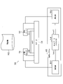
- FIG. 1 is an explanatory diagram showing a configuration of a high-frequency antenna measurement system according to the first embodiment.
- FIG. 2 is a block diagram showing a configuration of an RF circuit measurement system for measuring transmission characteristics of an RF circuit.
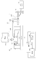
- FIG. 3 is an explanatory diagram showing another configuration of the high frequency antenna measurement system according to the first embodiment.
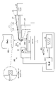
- FIG. 4 is an explanatory diagram showing the configuration of the high frequency antenna measurement system according to the second embodiment.
- FIG. 5 is an explanatory diagram showing the configuration of the high frequency antenna measurement system according to the third embodiment.
- FIG. 1 is an explanatory diagram showing a configuration of a high-frequency antenna measurement system according to the first embodiment.
- the high-frequency antenna measurement system 10 inputs a high-frequency signal to an on-chip high-frequency antenna AUT (Antenna Under Test, hereinafter referred to as AUT) to be measured, such as an on-chip antenna in the ultra-high frequency band, and radiates radio waves (radiated radio waves) radiated from the AUT. It is configured to measure the radiation characteristics of the AUT based on the received signal obtained by receiving the radiofrequency field.
- AUT Antenna Under Test
- the high-frequency antenna measurement system 10 has, as a main component, a stage 11 for holding and adjusting the position of the AUT, and a high-frequency signal output from the analysis system AS to supply power to the AUT.
- Power sensor Power Sensor
- TxProbe feeding probe
- RxANT receiving antenna
- the analysis system AS and the microscope MS are general ones used in the well-known RF circuit measurement system 50 and the like described later in FIG.
- the analysis system AS uses only one port (Port1) of a general network analyzer (Network Analyzer) NA, and after increasing the band of the high-frequency signal output from that port with the multiplier EX1. Power is supplied to the AUT via the power supply probe 12. Further, the microscope MS is used to optically confirm the position of the receiving antenna 14.
- the feeding probe 12 is attached to a pillar portion erected on the stage 11, an arm portion formed so as to project upward from the upper end of the pillar portion, and downward from the arm portion. , It is composed of a plurality of pins that are in electrical contact with the feeding terminal on the surface of the AUT.
- the detection probe (Rx-Probe) 13 is an existing one used in the RF circuit measurement system 50, and is not used for detecting the radiation characteristics of Austria.
- the detection probe 13 may be used as a support portion for supporting the receiving antenna 14. Further, as in the well-known RF circuit measurement system 50 described later in FIG. 2, the detection probe 13 is provided with the same configuration as the feeding probe 12 to detect a high frequency signal propagating in the transmission path on the AUT surface and to detect the AUT. The transmission characteristics of the device may be measured.
- FIG. 2 is a block diagram showing a configuration of an RF circuit measurement system that measures the transmission characteristics of an RF circuit.
- DUT Device Under Test
- the measurement system 50 is used.
- the RF circuit measurement system 50 feeds the high frequency signal output from the analysis system AS using the feeding probe (TxProbe) 52 to the DUT on the stage 51, and electrically contacts the circuit wiring of the DUT.
- the detection probe (RxProbe) 53 detects the high frequency signal and outputs it to the RF circuit measurement system 50.
- the analysis system AS increases the band of the signal output from one port (Port1) of the network analyzer NA with the extender EX1 and then DUTs via the feeding probe 52 of the RF circuit measurement system 50. Power to. Further, the high frequency signal detected by the detection probe 53 is reduced in band by the extender EX2, and then the signal is analyzed by the other port (Port2) of the network analyzer NA to measure the transmission characteristics of the DUT.
- the RF circuit measurement system 50 it is necessary to adjust the positions of the feeding probe 52 and the detection probe 53 to electrically contact the circuit wiring to be measured formed on the DUT surface.
- the circuit size of the DUT is on the order of mm or less, precise probe operation with a particle size of about um using the stage 51 is required. Therefore, as shown in FIG. 2, it is common to perform measurement by operating a probe using a microscope MS.
- the high frequency antenna measuring system 10 receives the radiated radio wave from the AUT composed of the on-chip antenna by the receiving antenna 14 and measures it by the power sensor 15. Therefore, in the receiving system that receives the radiated radio wave from the AUT, it is necessary to keep the position of the receiving antenna 14 at a position sufficiently high from the AUT. On the other hand, in the feeding system for feeding a high frequency signal to the AUT, as described above, it is necessary to adjust the position of the feeding probe 12 at the stage 11 using the microscope MS. Therefore, there is a need for a mechanism that allows the receiving antenna 14 to appropriately receive the radiated radio waves from the AUT with the microscope MS installed.
- the above problem is solved by using a waveguide antenna integrated with a connector as the receiving antenna 14. That is, the receiving antenna 14 is composed of a general waveguide 14A as a whole, and may be configured in a size suitable for the high frequency band of AUT, like the receiving system including the existing detection probe 13. As a result, the radiated radio wave can be received with a relatively high gain.
- a connector 14B for connecting to the power sensor 15 and outputting the received signal to the power sensor 15 is integrally formed.
- the received signal received by the receiving antenna 14 can be transmitted to the power sensor 15 without changing the transmission form as the waveguide 14A, and the transmission loss to the power sensor 15 can be reduced.
- the position of the receiving antenna 14 can be adjusted in the stage 11 as in the existing detection probe 13, it can be measured with high accuracy with respect to the radiation position of the AUT.
- the present embodiment includes a receiving antenna 14 for receiving the radiated radio wave from the high frequency antenna, and the receiving antenna 14 is integrally formed with a connector 14B for outputting the received signal to the power sensor 15 at the rear end. It is composed of a built-in waveguide.
- a receiving system that receives radiated radio waves from the AUT and measures the radiated characteristics can be constructed on the stage 11 with the microscope MS required for adjusting the position of the feeding probe 12 installed. Therefore, it is possible to appropriately measure the radiation characteristics such as the gain and the radiation pattern of the on-chip high-frequency antenna in the ultra-high frequency band with high accuracy.
- the receiving antenna 14 has a structure with high gain and low loss, it can be sufficiently measured without covering the power supplied from the network analyzer NA with a power amplifier or the like, and a measurement system can be realized at a relatively low cost. can do. Therefore, it is possible to construct an antenna measurement system for measuring the radiation characteristics of the on-chip high-frequency antenna only by changing a part of the receiving side of the conventional RF circuit measurement system. Therefore, it is possible to measure the radiation characteristics of the on-chip high-frequency antenna without constructing the antenna measurement system from scratch in an environment different from the RF circuit measurement system as in the past, and it takes time and effort to measure the RF front-end system. Can be significantly shortened.
- FIG. 3 is an explanatory diagram showing another configuration of the high frequency antenna measurement system according to the first embodiment.
- the receiving antenna 14 for example, an S-shaped curved portion 14D is formed in the vicinity of the waveguide-coaxial conversion adapter 14C, and the waveguide 16 forms the waveguide-.
- the position for receiving the radiated radio wave may be freely changed around the central axis O of the coaxial conversion adapter 14C.
- the position where the radiated radio wave is received by the receiving antenna 14 can be three-dimensionally changed (rotated) around the central axis O of the waveguide-coaxial adapter 13C, and the spatial radiation pattern of the AUT can be measured. can do. Further, by tilting the arrangement of the feeding system including the AUT by 90 degrees, it is possible to measure the other radiation surface (the E surface or the H surface, whichever is not measured).
- FIG. 4 is an explanatory diagram showing the configuration of the high frequency antenna measurement system according to the second embodiment.
- the position of the receiving antenna 14 can be adjusted in the two-dimensional direction along the substrate plane of the AUT, but when measuring the distance (height) X from the AUT to the receiving antenna 14. , It is difficult to reduce the measurement error of the distance X because it is necessary to use a measuring tool such as a caliper or a measure and finally rely on visual confirmation.
- the optical fiber 17 is connected to the distance sensor 18 using infrared rays, visible light, or the like, and the tip of the optical fiber 17 is arranged at the tip of the receiving antenna 14, thereby forming an AUTO. It is configured to measure the distance X between the surface and the tip of the receiving antenna 14.
- Other configurations of the high-frequency antenna measurement system 10 according to the present embodiment are the same as those in FIG. 1 or FIG. 3, and detailed description thereof will be omitted here.
- an optical signal emitted from the vicinity of the tip of the receiving antenna 14 toward the surface of the AUT via the optical fiber 17 and an optical signal reflected from the substrate of the AUT and returned are received via the optical fiber 17.
- the time difference between the transmission / reception timings of these optical signals is detected by the distance sensor 18, and the distance X between the tip of the receiving antenna and the surface of the AUT is calculated based on this time difference.
- the distance is measured with the receiving antenna 14 in contact with the reference surface, and the height is flexibly adjusted according to the difference in the substrate thickness and measurement environment by calibrating to 0 um (or mm). It can be carried out.
- the distance X can be measured by an objective method in which measurement errors such as visual inspection are significantly reduced. Further, by visually displaying the measured distance X value on the display, it is expected that the convenience at the time of measurement will be improved.
- a significant loss due to distance attenuation occurs due to a change in the distance between transmission and reception on the order of um.
- an objective and high-resolution measurement method of um order or less as in the present embodiment, it is possible to measure an appropriate antenna gain. Therefore, it is possible to appropriately measure the radiation characteristics such as the gain and the radiation pattern of the on-chip high-frequency antenna in the ultra-high frequency band with high accuracy.
- FIG. 5 is an explanatory diagram showing the configuration of the high frequency antenna measurement system according to the third embodiment.
- the position of the receiving antenna 14 in the two-dimensional direction along the substrate plane of the AUT is confirmed by the microscope MS in the same manner as the feeding probe 12. It is configured to adjust the position.
- the distance in the height direction from the feeding probe 12 is generated on the order of mm, the microscope MS is out of focus, and there is a concern that the position information between the AUTO and the receiving antenna 14 cannot be obtained accurately. Therefore, as a practical means, it is visually estimated from the position of the shadow of the receiving antenna 14 in a state of focusing on the substrate of the AUT.
- a laser pointer 19 is installed near the tip of the receiving antenna 14, and the laser beam 19A is emitted from the laser pointer 19 toward the AUT.
- the laser beam 19A emitted from the laser pointer 19 and reflected by the AUT substrate can be confirmed by the microscope MS, and the position of the receiving antenna 14 along the AUT substrate plane in the two-dimensional direction can be confirmed with high accuracy. Can be estimated.
- Other configurations of the high-frequency antenna measurement system 10 according to the present embodiment are the same as those in FIGS. 1, 3, or 4, and detailed description thereof will be omitted here.
Landscapes
- Physics & Mathematics (AREA)
- Electromagnetism (AREA)
- General Physics & Mathematics (AREA)
- Engineering & Computer Science (AREA)
- Computer Networks & Wireless Communication (AREA)
- Radar, Positioning & Navigation (AREA)
- Remote Sensing (AREA)
- Microelectronics & Electronic Packaging (AREA)
- Measurement Of Resistance Or Impedance (AREA)
- Variable-Direction Aerials And Aerial Arrays (AREA)
Abstract
本発明の高周波アンテナ測定システム(10)は、オンチップ高周波アンテナ(AUT)からの放射電波を受信する受信アンテナ(14)を備える。この受信アンテナ(14)は、後端に受信信号をパワーセンサ(15)へ出力するためのコネクタ(14B)が一体形成された導波管(14A)により構成される。これにより、給電プローブ(12)の位置調整に必要な顕微鏡(MS)を設置した状態で、AUTからの放射電波を受信して放射特性を測定する受信系をステージ(11)上に構築し、AUTの利得・放射パターンなどの放射特性を高精度で測定することが可能となる。
Description
本発明は、超高周波帯のオンチップ高周波アンテナに関する放射特性を測定する高周波アンテナ測定技術に関する。
携帯端末等の無線通信用デバイスにおいては、大容量・小型で持ち運びしやすいといった性質が強く求められる。これらを実現するためには、端末に内蔵される無線通信用デバイスの高周波(RF:Radio Frequency)フロントエンド部を担う高周波電子回路(以下、RF回路という)、および、高データレート化につながる高周波アンテナの広帯域化や小型化が重要である。
RFフロントエンドの帯域幅は、その構成要素である増幅器や周波数変換器等のアナログ回路および高周波アンテナ等の高周波部品の動作帯域幅で決定される。これら高周波部品の動作帯域幅は、その動作帯域の中心周波数に対する比率(比帯域と呼称される)が一定であると仮定される(例えば、非特許文献1など参照)。したがって、搬送波周波数を高周波化することで、高周波部品の動作帯域幅を大きくすることができる。また、搬送波周波数を高くすると、無線信号の波長が短くなることから、アナログ回路や高周波アンテナの波長で決まるインピーダンス素子(四分の一波長線路など)を含む構成部品を小型化することもできる。したがって、無線通信用デバイスの高データレート化、小型化といったニーズに応える手段として、搬送波周波数の高周波化は有効な手法である。
G. Hau, T. B. Nishimura and N. Iwata, "High Efficiency, Wide Dynamic Range Variable Gain and Power Amplifier MMICs for Wide-Band CDMA Handsets", IEEE Microw. Wireless Comp. Lett., Vol. 11, pp.13-15, Jan. 2001.
A. Dyck, M. Rosch, A. Tessman, A. Leuther, M. Kuri, S. Wagner, B. Gashi, J. Schafer and O. Ambacher, "A Transmitter System-in-Package at 300 GHz With an Off-Chip Antenna and GaAs-Based MMICs", IEEE Trans. Terahertz Sci. Technol, Vol. 9, pp.335-344, May 2019.
近年、前述した観点から、ミリ波やテラヘルツ(THz)といった超高周波を用いた高速・小型無線通信デバイスの研究が活発に行われている。ミリ波やテラヘルツ波を用いたRF回路や高周波アンテナの開発の際に問題となるのが、適切な特性評価を行うための測定環境の構築である。マイクロ波帯と比べたとき波長が1/10-1/100のサイズになることから、逓倍器による周波数変換ロスが大きく信号伝送時の損失が非常に大きく出力を確保するのが困難となる。また、RF回路や高周波アンテナは、mmオーダー以下の平方サイズで実装されることが多いため、測定時の目視確認が難しく再現性の観点で測定分解能の高い精密機器を用いた測定が必要となる(例えば、非特許文献2など参照)。
このような超高周波帯のオンチップ高周波アンテナを、測定対象アンテナAUT(Antenna Under Test、以下AUTという)として、その放射特性を測定する場合、AUTに高周波信号を給電する給電プローブを、顕微鏡で位置合わせする必要がある。しかし、顕微鏡を用いることでAUTからの放射電波を受信するための受信アンテナの設置が困難になり、放射特性の測定・評価が適切に実施できなくなる。また、受信アンテナを設置できた状態であっても、AUTから受信アンテナまでの距離をumオーダーで正確に把握することが難しい。さらに、顕微鏡を用いた場合でも、受信アンテナの水平方向の受信位置をAUTの放射中心点(水平方向の二次元空間)に合わせるのが難しく、AUTの利得を適切に測定することができない。したがって、従来の技術によれば、超高周波帯のオンチップ高周波アンテナに関する利得・放射パターンなどの放射特性を、高精度で適切に測定できないという問題点があった。
本発明はこのような課題を解決するためのものであり、超高周波帯のオンチップ高周波アンテナに関する利得・放射パターンなどの放射特性を高精度で適切に測定できる高周波アンテナ測定技術を提供することを目的としている。
このような目的を達成するために、本発明にかかる高周波アンテナ測定システムは、測定対象となるオンチップの高周波アンテナを保持するステージと、入力された高周波信号を前記高周波アンテナに給電する給電プローブと、前記高周波アンテナからの放射電波を受信する受信アンテナと、前記受信アンテナから出力された受信信号に基づいて前記高周波アンテナの放射特性を測定するパワーセンサとを備え、前記受信アンテナは、後端に前記受信信号を前記パワーセンサへ出力するためのコネクタが一体形成された導波管から構成される。
本発明によれば、超高周波帯のオンチップ高周波アンテナに関する利得・放射パターンなどの放射特性を高精度で適切に測定することができる。
次に、本発明の実施の形態について図面を参照して説明する。
[第1の実施の形態]
まず、図1を参照して、本発明の第1の実施の形態にかかる高周波アンテナ測定システム10について説明する。図1は、第1の実施の形態にかかる高周波アンテナ測定システムの構成を示す説明図である。
高周波アンテナ測定システム10は、例えば超高周波帯のオンチップアンテナなどの測定対象となるオンチップ高周波アンテナAUT(Antenna Under Test、以下AUTという)に高周波信号を入力し、AUTから放射された放射電波(放射電磁界)を受信して得られた受信信号に基づいて、AUTの放射特性を測定するように構成されている。
[第1の実施の形態]
まず、図1を参照して、本発明の第1の実施の形態にかかる高周波アンテナ測定システム10について説明する。図1は、第1の実施の形態にかかる高周波アンテナ測定システムの構成を示す説明図である。
高周波アンテナ測定システム10は、例えば超高周波帯のオンチップアンテナなどの測定対象となるオンチップ高周波アンテナAUT(Antenna Under Test、以下AUTという)に高周波信号を入力し、AUTから放射された放射電波(放射電磁界)を受信して得られた受信信号に基づいて、AUTの放射特性を測定するように構成されている。
図1に示すように、高周波アンテナ測定システム10は、主な構成装置として、AUTを保持し位置調整するためのステージ(Stage)11、解析システムASから出力された高周波信号をAUTに給電するための給電プローブ(Tx Probe)12、AUTからの放射電波を受信するための受信アンテナ(Rx ANT)14、受信アンテナ14で得られた受信信号からAUTの放射特性を検出するパワーセンサ(Power Sensor)15とを備えている。
このうち、解析システムASおよび顕微鏡(Microscope)MSは、図2で後述する周知のRF回路測定システム50などで用いられる一般的なものである。特に、解析システムASは、一般的なネットワークアナライザ(Network Analyzer)NAの一方のポート(Port1)のみを用い、そのポートから出力した高周波信号を、逓倍器(Extender)EX1で高帯域化した後、給電プローブ12を介してAUTへ給電する。また、顕微鏡MSは、受信アンテナ14の位置を光学的に確認するために用いられる。
給電プローブ12は、ステージ11に立設された柱部と、その柱部の上端からAUTの上方に向けて突出するように形成された腕部と、その腕部から下方に向けて取り付けられて、AUT表面の給電端子と電気的に接触する複数のピンとから構成されている。
検出プローブ(Rx-Probe)13は、RF回路測定システム50で用いられる既存のものであり、AUTの放射特性の検出には用いられていない。なお、検出プローブ13は、受信アンテナ14を支持する支持部として用いてもよい。また、図2で後述する周知のRF回路測定システム50のように、給電プローブ12と同様な構成を検出プローブ13に備えることにより、AUT表面の伝送路を伝搬する高周波信号を検出して、AUTの伝送特性を測定するようにしてもよい。
検出プローブ(Rx-Probe)13は、RF回路測定システム50で用いられる既存のものであり、AUTの放射特性の検出には用いられていない。なお、検出プローブ13は、受信アンテナ14を支持する支持部として用いてもよい。また、図2で後述する周知のRF回路測定システム50のように、給電プローブ12と同様な構成を検出プローブ13に備えることにより、AUT表面の伝送路を伝搬する高周波信号を検出して、AUTの伝送特性を測定するようにしてもよい。
図2は、RF回路の伝送特性を測定するRF回路測定システムの構成を示すブロック図である。一般に、ミリ波以上の超高周波帯のRF回路(DUT:Device Under Test、以下DUTという)の伝送特性を、パッケージングせず直接測定する際には、図2に示すような、周知のRF回路測定システム50が用いられる。このRF回路測定システム50は、給電プローブ(Tx Probe)52を用いて解析システムASから出力された高周波信号を、ステージ(Stage)51上のDUTに給電し、DUTの回路配線に電気的に接触することにより検出プローブ(Rx Probe)53で高周波信号を検出し、RF回路測定システム50へ出力する。
解析システムASは、ネットワークアナライザ(Network Analyzer)NAの一方のポート(Port1)から出力した信号を逓倍器(Extender)EX1で高帯域化した後、RF回路測定システム50の給電プローブ52を介してDUTへ給電する。また、検出プローブ53で検出した高周波信号を逓倍器(Extender)EX2で低帯域化した後、ネットワークアナライザNAの他方のポート(Port2)で信号解析することにより、DUTの伝送特性を測定する。
この際、RF回路測定システム50では、給電プローブ52および検出プローブ53の位置を調整して、DUT表面に形成された、測定対象となる回路配線と電気的に接触させる必要がある。特に、DUTの回路サイズがmmオーダー以下である場合、ステージ51を用いたum程度の粒度での緻密なプローブ操作が求められる。したがって、図2のように顕微鏡(Microscope)MSを用いたプローブ操作によって測定を行うのが一般的である。
しかし、高周波アンテナ測定システム10は、オンチップアンテナからなるAUTからの放射電波を受信アンテナ14で受信してパワーセンサ15で測定する。このため、AUTからの放射電波を受信する受信系では、受信アンテナ14の位置をAUTから十分な高さ位置に保持する必要がある。一方、AUTに高周波信号を給電する給電系では、前述したように、顕微鏡MSを用いてステージ11で給電プローブ12の位置を調整する必要がある。したがって、顕微鏡MSを設置した状態で、AUTからの放射電波を受信アンテナ14で適切に受信できる機構が求められる。
本実施の形態では、図1に示すように、受信アンテナ14として、コネクタ一体型の導波管アンテナを用いることで、上記の課題を解決した。すなわち、受信アンテナ14は、全体として一般的な導波管14Aからなり、既存の検出プローブ13を含む受信系と同様に、AUTの高周波数帯に適応したサイズで構成すればよい。これにより、比較的高い利得で放射電波を受信することができる。
また、受信アンテナ14の後端には、パワーセンサ15と接続して受信信号をパワーセンサ15へ出力するためのコネクタ14Bが一体形成されている。これにより、受信アンテナ14で受信した受信信号を、導波管14Aのまま伝送形態を変えずにパワーセンサ15まで伝送でき、パワーセンサ15までの伝送損失を低減できる。さらに、受信アンテナ14の位置も、既存の検出プローブ13と同様にステージ11で調整できるため、AUTの放射位置に対して高い精度で合わせて測定できる。
[第1の実施の形態の効果]
このように、本実施の形態は、高周波アンテナからの放射電波を受信する受信アンテナ14を備え、この受信アンテナ14を、後端に受信信号をパワーセンサ15へ出力するためのコネクタ14Bが一体形成された導波管により構成したものである。
これにより、給電プローブ12の位置調整に必要な顕微鏡MSを設置した状態で、AUTからの放射電波を受信して放射特性を測定する受信系をステージ11上に構築することができる。したがって、超高周波帯のオンチップ高周波アンテナに関する利得・放射パターンなどの放射特性を高精度で適切に測定することが可能となる。
このように、本実施の形態は、高周波アンテナからの放射電波を受信する受信アンテナ14を備え、この受信アンテナ14を、後端に受信信号をパワーセンサ15へ出力するためのコネクタ14Bが一体形成された導波管により構成したものである。
これにより、給電プローブ12の位置調整に必要な顕微鏡MSを設置した状態で、AUTからの放射電波を受信して放射特性を測定する受信系をステージ11上に構築することができる。したがって、超高周波帯のオンチップ高周波アンテナに関する利得・放射パターンなどの放射特性を高精度で適切に測定することが可能となる。
また、受信アンテナ14は、高利得かつ低損失な構造を有するため、パワーアンプなどで、ネットワークアナライザNAからの供給電力をカバーすることなく十分測定可能になり、比較的低コストで測定系を実現することができる。したがって、従来のRF回路測定系の受信側の一部を変更するだけで、オンチップ高周波アンテナの放射特性を測定するアンテナ測定系を構築することができる。このため、従来のように、RF回路測定系とは異なる環境でアンテナ測定系を一から構築しなくても、オンチップ高周波アンテナの放射特性を測定でき、RFフロントエンドシステムの測定の手間と時間を大幅に短縮することが可能となる。
また、本実施の形態において、図3に示すように、受信アンテナ14については、コネクタ14Bとして、導波管14Aをパワーセンサ15の同軸ケーブル15Aに変換接続する導波管-同軸変換アダプタ14Cを用いてもよい。図3は、第1の実施の形態にかかる高周波アンテナ測定システムの他の構成を示す説明図である。この際、受信アンテナ14(導波管14A)のうち、導波管-同軸変換アダプタ14Cの近傍に、例えばS字形状の曲部14Dを形成し、保持台(Stand)16により導波管-同軸変換アダプタ14Cの中心軸Oを中心として、放射電波を受信する位置を変更自在に保持するようにしてもよい。
これにより、受信アンテナ14で放射電波を受信する位置を、導波管-同軸アダプタ13Cの中心軸Oを中心にして三次元的に変更(回転)することができ、AUTの空間放射パターンを測定することができる。また、AUTを含む給電系の配置を90度傾けることで、もう一方の放射面(E面、H面のうち測定していない方)を測定することも可能である。
[第2の実施の形態]
次に、図4を参照して、本発明の第2の実施の形態にかかる高周波アンテナ測定システム10について説明する。図4は、第2の実施の形態にかかる高周波アンテナ測定システムの構成を示す説明図である。
次に、図4を参照して、本発明の第2の実施の形態にかかる高周波アンテナ測定システム10について説明する。図4は、第2の実施の形態にかかる高周波アンテナ測定システムの構成を示す説明図である。
前述の図1に示した測定系では、受信アンテナ14について、AUTの基板平面に沿った二次元方向の位置調整は可能だが、AUTから受信アンテナ14までの距離(高さ)Xを計測する場合、ノギスやメジャーなどの計測用具を使用し最終的には目視確認に頼ることになり、距離Xの計測誤差を低減することが難しい。
本実施の形態は、図4のように、赤外線・可視光等を用いた距離センサ18に光ファイバ17を接続し、光ファイバ17の先端を受信アンテナ14の先端部分に配置することによって、AUT表面と受信アンテナ14の先端との距離Xを計測するように構成したものである。本実施の形態にかかる高周波アンテナ測定システム10のその他の構成については、図1または図3と同様であり、ここでの詳細な説明は省略する。
図4において、光ファイバ17を介して受信アンテナ14の先端近傍からAUTの表面に向けて出射された光信号と、AUTの基板から反射して戻ってきた光信号を光ファイバ17を介して受信し、これらの光信号の送受信タイミングの時間差が距離センサ18で検出され、この時間差に基づいて受信アンテナの先端とAUTの表面との距離Xが算出される。測定の際は、まず、基準面に受信アンテナ14を接触させた状態で距離を計測し、0um(もしくはmm)と校正することで基板厚や測定環境の違いに合わせてフレキシブルに高さ調整を行うことができる。
[第2の実施の形態の効果]
このように、本実施の形態によれば、目視等の測定誤差が大幅に低減された客観的な手法で、距離Xを計測することができる。また、計測した距離Xの値を表示器で可視表示することで測定時の利便性向上が見込める。通常、ミリ波以上の超高周波帯のアンテナ測定では、umオーダーの送受信間距離の変化で、距離減衰による有意な損失が発生する。本実施の形態のように、客観的かつumオーダー以下の分解能の高い計測方法を用いることで、適切なアンテナ利得を測定することが可能となる。したがって、超高周波帯のオンチップ高周波アンテナに関する利得・放射パターンなどの放射特性を高精度で適切に測定することが可能となる。
このように、本実施の形態によれば、目視等の測定誤差が大幅に低減された客観的な手法で、距離Xを計測することができる。また、計測した距離Xの値を表示器で可視表示することで測定時の利便性向上が見込める。通常、ミリ波以上の超高周波帯のアンテナ測定では、umオーダーの送受信間距離の変化で、距離減衰による有意な損失が発生する。本実施の形態のように、客観的かつumオーダー以下の分解能の高い計測方法を用いることで、適切なアンテナ利得を測定することが可能となる。したがって、超高周波帯のオンチップ高周波アンテナに関する利得・放射パターンなどの放射特性を高精度で適切に測定することが可能となる。
[第3の実施の形態]
次に、図5を参照して、本発明の第3の実施の形態にかかる高周波アンテナ測定システム10について説明する。図5は、第3の実施の形態にかかる高周波アンテナ測定システムの構成を示す説明図である。
次に、図5を参照して、本発明の第3の実施の形態にかかる高周波アンテナ測定システム10について説明する。図5は、第3の実施の形態にかかる高周波アンテナ測定システムの構成を示す説明図である。
前述の図1,図3、および図4に示した測定系では、受信アンテナ14に関する、AUTの基板平面に沿った二次元方向の位置は、給電プローブ12と同様に、顕微鏡MSで確認しながら位置調整をする構成となっている。しかし、測定時には給電プローブ12との高さ方向の距離がmmオーダーで発生して顕微鏡MSの焦点が合わず、AUTと受信アンテナ14との位置情報が正確に得られない懸念がある。このため、現実的な手段として、AUTの基板に焦点を合わせた状態で受信アンテナ14の影の位置から目視で推定することになる。
本実施の形態は、図5のように、受信アンテナ14の先端近傍にレーザポインタ19を設置し、レーザポインタ19からAUTに向けてレーザビーム19Aを出射するように構成したものである。これにより、レーザポインタ19から出射されてAUTの基板で反射して戻ってきたレーザビーム19Aを顕微鏡MSで確認でき、AUTの基板平面に沿った受信アンテナ14の二次元方向の位置を高い精度で推定することができる。本実施の形態にかかる高周波アンテナ測定システム10のその他の構成については、図1、図3、または図4と同様であり、ここでの詳細な説明は省略する。
顕微鏡MSで確認するレーザビーム19Aに求められる集光度(二次元的な広がりの範囲)や強度は、測定サンプルによって変化する。このため、測定サンプルのスケールが小さい場合は狭ビームで比較的強度の小さいレーザ、スケールが大きい場合は比較的広いビームで強度の大きいレーザというように、レーザビーム19Aを使い分ければよい。このようなレーザビーム19Aの使い分けは、レーザポインタ19の先端に装着するレンズを用途ごとに付け替えることで実現可能である。
[第3の実施の形態の効果]
このように、本実施の形態によれば、AUTの基板平面に沿った受信アンテナ14二次元方向の位置を、高い精度で推定することが可能となる。したがって、超高周波帯のオンチップ高周波アンテナに関する利得・放射パターンなどの放射特性を高精度で適切に測定することが可能となる。
このように、本実施の形態によれば、AUTの基板平面に沿った受信アンテナ14二次元方向の位置を、高い精度で推定することが可能となる。したがって、超高周波帯のオンチップ高周波アンテナに関する利得・放射パターンなどの放射特性を高精度で適切に測定することが可能となる。
[実施の形態の拡張]
以上、実施形態を参照して本発明を説明したが、本発明は上記実施形態に限定されるものではない。本発明の構成や詳細には、本発明のスコープ内で当業者が理解しうる様々な変更をすることができる。また、各実施形態については、矛盾しない範囲で任意に組み合わせて実施することができる。
以上、実施形態を参照して本発明を説明したが、本発明は上記実施形態に限定されるものではない。本発明の構成や詳細には、本発明のスコープ内で当業者が理解しうる様々な変更をすることができる。また、各実施形態については、矛盾しない範囲で任意に組み合わせて実施することができる。
10…高周波アンテナ測定システム、11…ステージ、12…給電プローブ、13…検出プローブ、14…受信アンテナ、14A…導波管、14B…コネクタ、14C…導波管-同軸変換アダプタ、14D…曲部、15…パワーセンサ、15A…同軸ケーブル、16…保持台、17…光ファイバ、18…距離センサ、19…レーザポインタ、AUT…オンチップ高周波アンテナ、AS…解析システム、NA…ネットワークアナライザ、EX1…逓倍器、MS…顕微鏡。
Claims (5)
- 測定対象となるオンチップの高周波アンテナを保持するステージと、
入力された高周波信号を前記高周波アンテナに給電する給電プローブと、
前記高周波アンテナからの放射電波を受信する受信アンテナと、
前記受信アンテナから出力された受信信号に基づいて前記高周波アンテナの放射特性を測定するパワーセンサとを備え、
前記受信アンテナは、後端に前記受信信号を前記パワーセンサへ出力するためのコネクタが一体形成された導波管から構成される
ことを特徴とする高周波アンテナ測定システム。 - 請求項1に記載の高周波アンテナ測定システムにおいて、
前記コネクタは、前記導波管を前記パワーセンサの同軸ケーブルに変換する変換アダプタから構成されること
を特徴とする高周波アンテナ測定システム。 - 請求項2に記載の高周波アンテナ測定システムにおいて、
前記受信アンテナは、前記コネクタの近傍に曲部が形成されており、前記変換アダプタの中心軸を中心として、前記放射電波を受信する位置を変更自在に保持されていること
を特徴とする高周波アンテナ測定システム。 - 請求項1~請求項3のいずれかに記載の高周波アンテナ測定システムにおいて、
光ファイバを介して前記受信アンテナの先端近傍から前記高周波アンテナの表面に向けて光信号を出射し、前記光ファイバを介して前記高周波アンテナの表面で反射した前記光信号を受信する距離センサを備え、
前記距離センサは、前記光信号の送受信タイミングの時間差に基づいて前記受信アンテナの先端と前記高周波アンテナの表面との距離を算出すること
を特徴とする高周波アンテナ測定システム。 - 請求項1~請求項4のいずれかに記載の高周波アンテナ測定システムにおいて、
前記受信アンテナの先端近傍に配置され、前記高周波アンテナの表面に向けてレーザビームを出射するレーザポインタを備え、
前記高周波アンテナの表面で反射した前記レーザビームを用いて、前記高周波アンテナの基板平面に沿った、前記受信アンテナの二次元方向の位置を推定するように構成される
ことを特徴とする高周波アンテナ測定システム。
Priority Applications (2)
| Application Number | Priority Date | Filing Date | Title |
|---|---|---|---|
| US18/247,032 US12265110B2 (en) | 2020-11-04 | 2020-11-04 | High-frequency antenna measurement system |
| PCT/JP2020/041168 WO2022097192A1 (ja) | 2020-11-04 | 2020-11-04 | 高周波アンテナ測定システム |
Applications Claiming Priority (1)
| Application Number | Priority Date | Filing Date | Title |
|---|---|---|---|
| PCT/JP2020/041168 WO2022097192A1 (ja) | 2020-11-04 | 2020-11-04 | 高周波アンテナ測定システム |
Publications (1)
| Publication Number | Publication Date |
|---|---|
| WO2022097192A1 true WO2022097192A1 (ja) | 2022-05-12 |
Family
ID=81457605
Family Applications (1)
| Application Number | Title | Priority Date | Filing Date |
|---|---|---|---|
| PCT/JP2020/041168 Ceased WO2022097192A1 (ja) | 2020-11-04 | 2020-11-04 | 高周波アンテナ測定システム |
Country Status (2)
| Country | Link |
|---|---|
| US (1) | US12265110B2 (ja) |
| WO (1) | WO2022097192A1 (ja) |
Citations (6)
| Publication number | Priority date | Publication date | Assignee | Title |
|---|---|---|---|---|
| JP2002243782A (ja) * | 2001-02-19 | 2002-08-28 | Anritsu Corp | 近傍界測定方法および近傍界測定システム |
| US20070126427A1 (en) * | 2003-11-25 | 2007-06-07 | Ae-Kyoung Lee | Method for measuring electromagnetic radiation pattern and gain of radiator using tem waveguide |
| JP2010159990A (ja) * | 2009-01-06 | 2010-07-22 | Toshiba Corp | 電磁波測定装置及び方法 |
| US20140104092A1 (en) * | 2012-10-12 | 2014-04-17 | International Business Machines Corporation | Radiation signal measurement system for millimeter wave transceivers |
| US20180205821A1 (en) * | 2017-01-19 | 2018-07-19 | Rohde & Schwarz Gmbh & Co. Kg | Test device and test method |
| CN110954755A (zh) * | 2018-09-26 | 2020-04-03 | 川升股份有限公司 | 天线辐射场型自动量测系统 |
Family Cites Families (3)
| Publication number | Priority date | Publication date | Assignee | Title |
|---|---|---|---|---|
| KR101988406B1 (ko) * | 2015-06-26 | 2019-06-12 | 스카이워크스 솔루션즈, 인코포레이티드 | 집성된 반송파의 개별 반송파의 전력 검출 |
| EP3561528B1 (en) * | 2018-04-25 | 2025-02-12 | Rohde & Schwarz GmbH & Co. KG | Measurement arrangement and measurement method |
| US11664833B2 (en) * | 2019-07-23 | 2023-05-30 | Skyworks Solutions, Inc. | Power detectors with enhanced dynamic range |
-
2020
- 2020-11-04 US US18/247,032 patent/US12265110B2/en active Active
- 2020-11-04 WO PCT/JP2020/041168 patent/WO2022097192A1/ja not_active Ceased
Patent Citations (6)
| Publication number | Priority date | Publication date | Assignee | Title |
|---|---|---|---|---|
| JP2002243782A (ja) * | 2001-02-19 | 2002-08-28 | Anritsu Corp | 近傍界測定方法および近傍界測定システム |
| US20070126427A1 (en) * | 2003-11-25 | 2007-06-07 | Ae-Kyoung Lee | Method for measuring electromagnetic radiation pattern and gain of radiator using tem waveguide |
| JP2010159990A (ja) * | 2009-01-06 | 2010-07-22 | Toshiba Corp | 電磁波測定装置及び方法 |
| US20140104092A1 (en) * | 2012-10-12 | 2014-04-17 | International Business Machines Corporation | Radiation signal measurement system for millimeter wave transceivers |
| US20180205821A1 (en) * | 2017-01-19 | 2018-07-19 | Rohde & Schwarz Gmbh & Co. Kg | Test device and test method |
| CN110954755A (zh) * | 2018-09-26 | 2020-04-03 | 川升股份有限公司 | 天线辐射场型自动量测系统 |
Also Published As
| Publication number | Publication date |
|---|---|
| US20230358796A1 (en) | 2023-11-09 |
| US12265110B2 (en) | 2025-04-01 |
Similar Documents
| Publication | Publication Date | Title |
|---|---|---|
| JP7091563B2 (ja) | 検査用アンテナシステム | |
| JP5427606B2 (ja) | 放射電力測定方法及び放射電力測定装置 | |
| CN115047256A (zh) | 一种阵列天线多通道并行测试装置、测试方法及校准方法 | |
| KR101360280B1 (ko) | 흡수재를 구비하지 않은 다중채널 근접장 측정 시스템 | |
| US20180006745A1 (en) | Compact system for characterizing a device under test (dut) having integrated antenna array | |
| CN111707877A (zh) | 一种射频发射机杂散辐射测试系统及测试方法 | |
| CN110007157B (zh) | 天线测量系统以及天线测量方法 | |
| CN110018361B (zh) | 一种相控阵天线增益噪声温度比值测量方法及系统 | |
| CN110401500B (zh) | 测量装置和测量方法 | |
| US11372037B2 (en) | Freespace antenna measurement system | |
| CN112558001B (zh) | 一种脉冲高功率现场校准装置和方法 | |
| JP2013503331A (ja) | ハイブリッド反射率計システム | |
| US20260051926A1 (en) | High-performance probe for near-field antenna measurement | |
| JP2000338155A (ja) | アンテナ測定システム | |
| TWI422838B (zh) | 多頻道無吸收器之近場測量系統 | |
| US20200386800A1 (en) | System and method of characterizing a quiet zone of an over-the-air testing space | |
| Boehm et al. | Accuracy evaluation for antenna measurements at mm-wave frequencies | |
| US12265110B2 (en) | High-frequency antenna measurement system | |
| CN115219804A (zh) | 一种太赫兹天线和天线罩电性能近场测试装置及方法 | |
| TWI823691B (zh) | 用於對包括多個天線的射頻裝置進行表徵的測量裝置、包括測量裝置的自動化測試設備以及用於對包括多個天線的被測試器件進行表徵的方法 | |
| Zatta et al. | CMOS camera-type THz compact antenna test range for far-field radiation pattern analysis | |
| TWI847639B (zh) | 基於近場到遠場轉換的天線場型的測量裝置和測量方法 | |
| CN210835076U (zh) | 一种用于大功率辐射设备性能测试的系统 | |
| Hong et al. | Ka-band electric-field probe calibration system with rotating and linear motion | |
| Fang et al. | Millimeter wave antenna in package (AiP) measured in far-field by a vertical probe station |
Legal Events
| Date | Code | Title | Description |
|---|---|---|---|
| 121 | Ep: the epo has been informed by wipo that ep was designated in this application |
Ref document number: 20960746 Country of ref document: EP Kind code of ref document: A1 |
|
| NENP | Non-entry into the national phase |
Ref country code: DE |
|
| 122 | Ep: pct application non-entry in european phase |
Ref document number: 20960746 Country of ref document: EP Kind code of ref document: A1 |
|
| NENP | Non-entry into the national phase |
Ref country code: JP |
|
| WWG | Wipo information: grant in national office |
Ref document number: 18247032 Country of ref document: US |