WO2022092095A1 - Wound core - Google Patents
Wound core Download PDFInfo
- Publication number
- WO2022092095A1 WO2022092095A1 PCT/JP2021/039518 JP2021039518W WO2022092095A1 WO 2022092095 A1 WO2022092095 A1 WO 2022092095A1 JP 2021039518 W JP2021039518 W JP 2021039518W WO 2022092095 A1 WO2022092095 A1 WO 2022092095A1
- Authority
- WO
- WIPO (PCT)
- Prior art keywords
- grain
- oriented electrical
- electrical steel
- steel sheet
- laminated
- Prior art date
Links
- 229910001224 Grain-oriented electrical steel Inorganic materials 0.000 claims abstract description 97
- 238000005452 bending Methods 0.000 claims abstract description 18
- 229910000831 Steel Inorganic materials 0.000 claims description 159
- 239000010959 steel Substances 0.000 claims description 159
- XEEYBQQBJWHFJM-UHFFFAOYSA-N iron Substances [Fe] XEEYBQQBJWHFJM-UHFFFAOYSA-N 0.000 claims description 136
- 239000000203 mixture Substances 0.000 claims description 15
- 239000000126 substance Substances 0.000 claims description 15
- 238000005259 measurement Methods 0.000 claims description 9
- 239000012535 impurity Substances 0.000 claims description 5
- 239000011229 interlayer Substances 0.000 abstract description 17
- 239000011162 core material Substances 0.000 description 68
- 238000000034 method Methods 0.000 description 37
- 230000000694 effects Effects 0.000 description 25
- 230000004907 flux Effects 0.000 description 22
- 238000004519 manufacturing process Methods 0.000 description 20
- 238000004804 winding Methods 0.000 description 19
- 230000008859 change Effects 0.000 description 18
- 238000000137 annealing Methods 0.000 description 17
- 238000005096 rolling process Methods 0.000 description 15
- 239000000463 material Substances 0.000 description 14
- 229910000976 Electrical steel Inorganic materials 0.000 description 11
- 229910052742 iron Inorganic materials 0.000 description 11
- 230000002093 peripheral effect Effects 0.000 description 11
- 229910000576 Laminated steel Inorganic materials 0.000 description 10
- 239000010410 layer Substances 0.000 description 10
- 239000011248 coating agent Substances 0.000 description 9
- 238000000576 coating method Methods 0.000 description 9
- 238000012360 testing method Methods 0.000 description 9
- 230000001276 controlling effect Effects 0.000 description 8
- 238000009826 distribution Methods 0.000 description 8
- 230000009467 reduction Effects 0.000 description 7
- 239000013078 crystal Substances 0.000 description 6
- 238000006073 displacement reaction Methods 0.000 description 5
- 230000008569 process Effects 0.000 description 5
- 238000010438 heat treatment Methods 0.000 description 4
- 230000009471 action Effects 0.000 description 3
- 239000010960 cold rolled steel Substances 0.000 description 3
- 238000005520 cutting process Methods 0.000 description 3
- 238000010586 diagram Methods 0.000 description 3
- 238000010030 laminating Methods 0.000 description 3
- 230000005381 magnetic domain Effects 0.000 description 3
- 241000192308 Agrostis hyemalis Species 0.000 description 2
- 238000003486 chemical etching Methods 0.000 description 2
- 239000011651 chromium Substances 0.000 description 2
- 238000000605 extraction Methods 0.000 description 2
- 239000012467 final product Substances 0.000 description 2
- 238000005121 nitriding Methods 0.000 description 2
- 238000003825 pressing Methods 0.000 description 2
- 238000012545 processing Methods 0.000 description 2
- 238000005070 sampling Methods 0.000 description 2
- 230000003068 static effect Effects 0.000 description 2
- 230000003746 surface roughness Effects 0.000 description 2
- 238000010998 test method Methods 0.000 description 2
- 238000012935 Averaging Methods 0.000 description 1
- VYZAMTAEIAYCRO-UHFFFAOYSA-N Chromium Chemical compound [Cr] VYZAMTAEIAYCRO-UHFFFAOYSA-N 0.000 description 1
- 229910019142 PO4 Inorganic materials 0.000 description 1
- VYPSYNLAJGMNEJ-UHFFFAOYSA-N Silicium dioxide Chemical compound O=[Si]=O VYPSYNLAJGMNEJ-UHFFFAOYSA-N 0.000 description 1
- 238000010521 absorption reaction Methods 0.000 description 1
- 229910021529 ammonia Inorganic materials 0.000 description 1
- 238000004458 analytical method Methods 0.000 description 1
- 230000005540 biological transmission Effects 0.000 description 1
- 238000011088 calibration curve Methods 0.000 description 1
- 229910052804 chromium Inorganic materials 0.000 description 1
- 238000005097 cold rolling Methods 0.000 description 1
- 239000008119 colloidal silica Substances 0.000 description 1
- 230000000052 comparative effect Effects 0.000 description 1
- 230000000295 complement effect Effects 0.000 description 1
- 238000005261 decarburization Methods 0.000 description 1
- 238000001514 detection method Methods 0.000 description 1
- 230000006866 deterioration Effects 0.000 description 1
- 238000005516 engineering process Methods 0.000 description 1
- 239000003822 epoxy resin Substances 0.000 description 1
- 238000011156 evaluation Methods 0.000 description 1
- HJUFTIJOISQSKQ-UHFFFAOYSA-N fenoxycarb Chemical compound C1=CC(OCCNC(=O)OCC)=CC=C1OC1=CC=CC=C1 HJUFTIJOISQSKQ-UHFFFAOYSA-N 0.000 description 1
- 239000011521 glass Substances 0.000 description 1
- 238000000227 grinding Methods 0.000 description 1
- 238000009499 grossing Methods 0.000 description 1
- LNEPOXFFQSENCJ-UHFFFAOYSA-N haloperidol Chemical compound C1CC(O)(C=2C=CC(Cl)=CC=2)CCN1CCCC(=O)C1=CC=C(F)C=C1 LNEPOXFFQSENCJ-UHFFFAOYSA-N 0.000 description 1
- 238000005098 hot rolling Methods 0.000 description 1
- 230000001771 impaired effect Effects 0.000 description 1
- 239000011261 inert gas Substances 0.000 description 1
- 238000002347 injection Methods 0.000 description 1
- 239000007924 injection Substances 0.000 description 1
- 230000010354 integration Effects 0.000 description 1
- 230000001050 lubricating effect Effects 0.000 description 1
- 238000003754 machining Methods 0.000 description 1
- 230000005415 magnetization Effects 0.000 description 1
- 230000007246 mechanism Effects 0.000 description 1
- 230000010534 mechanism of action Effects 0.000 description 1
- 238000012986 modification Methods 0.000 description 1
- 230000004048 modification Effects 0.000 description 1
- 238000000465 moulding Methods 0.000 description 1
- 238000010422 painting Methods 0.000 description 1
- 239000002245 particle Substances 0.000 description 1
- 230000000737 periodic effect Effects 0.000 description 1
- NBIIXXVUZAFLBC-UHFFFAOYSA-K phosphate Chemical compound [O-]P([O-])([O-])=O NBIIXXVUZAFLBC-UHFFFAOYSA-K 0.000 description 1
- 239000010452 phosphate Substances 0.000 description 1
- 238000005554 pickling Methods 0.000 description 1
- 229920000647 polyepoxide Polymers 0.000 description 1
- 239000000047 product Substances 0.000 description 1
- 230000001737 promoting effect Effects 0.000 description 1
- 239000002994 raw material Substances 0.000 description 1
- 238000001953 recrystallisation Methods 0.000 description 1
- 230000001105 regulatory effect Effects 0.000 description 1
- 238000010008 shearing Methods 0.000 description 1
- 239000000243 solution Substances 0.000 description 1
- 238000004611 spectroscopical analysis Methods 0.000 description 1
- 239000007921 spray Substances 0.000 description 1
- 239000002436 steel type Substances 0.000 description 1
- 238000004381 surface treatment Methods 0.000 description 1
- 238000009864 tensile test Methods 0.000 description 1
Images


Classifications
-
- H—ELECTRICITY
- H01—ELECTRIC ELEMENTS
- H01F—MAGNETS; INDUCTANCES; TRANSFORMERS; SELECTION OF MATERIALS FOR THEIR MAGNETIC PROPERTIES
- H01F3/00—Cores, Yokes, or armatures
- H01F3/02—Cores, Yokes, or armatures made from sheets
-
- H—ELECTRICITY
- H01—ELECTRIC ELEMENTS
- H01F—MAGNETS; INDUCTANCES; TRANSFORMERS; SELECTION OF MATERIALS FOR THEIR MAGNETIC PROPERTIES
- H01F27/00—Details of transformers or inductances, in general
- H01F27/24—Magnetic cores
- H01F27/245—Magnetic cores made from sheets, e.g. grain-oriented
- H01F27/2455—Magnetic cores made from sheets, e.g. grain-oriented using bent laminations
-
- C—CHEMISTRY; METALLURGY
- C21—METALLURGY OF IRON
- C21D—MODIFYING THE PHYSICAL STRUCTURE OF FERROUS METALS; GENERAL DEVICES FOR HEAT TREATMENT OF FERROUS OR NON-FERROUS METALS OR ALLOYS; MAKING METAL MALLEABLE, e.g. BY DECARBURISATION OR TEMPERING
- C21D8/00—Modifying the physical properties by deformation combined with, or followed by, heat treatment
- C21D8/12—Modifying the physical properties by deformation combined with, or followed by, heat treatment during manufacturing of articles with special electromagnetic properties
-
- C—CHEMISTRY; METALLURGY
- C22—METALLURGY; FERROUS OR NON-FERROUS ALLOYS; TREATMENT OF ALLOYS OR NON-FERROUS METALS
- C22C—ALLOYS
- C22C38/00—Ferrous alloys, e.g. steel alloys
- C22C38/02—Ferrous alloys, e.g. steel alloys containing silicon
-
- C—CHEMISTRY; METALLURGY
- C22—METALLURGY; FERROUS OR NON-FERROUS ALLOYS; TREATMENT OF ALLOYS OR NON-FERROUS METALS
- C22C—ALLOYS
- C22C38/00—Ferrous alloys, e.g. steel alloys
- C22C38/60—Ferrous alloys, e.g. steel alloys containing lead, selenium, tellurium, or antimony, or more than 0.04% by weight of sulfur
-
- H—ELECTRICITY
- H01—ELECTRIC ELEMENTS
- H01F—MAGNETS; INDUCTANCES; TRANSFORMERS; SELECTION OF MATERIALS FOR THEIR MAGNETIC PROPERTIES
- H01F1/00—Magnets or magnetic bodies characterised by the magnetic materials therefor; Selection of materials for their magnetic properties
- H01F1/01—Magnets or magnetic bodies characterised by the magnetic materials therefor; Selection of materials for their magnetic properties of inorganic materials
- H01F1/03—Magnets or magnetic bodies characterised by the magnetic materials therefor; Selection of materials for their magnetic properties of inorganic materials characterised by their coercivity
- H01F1/12—Magnets or magnetic bodies characterised by the magnetic materials therefor; Selection of materials for their magnetic properties of inorganic materials characterised by their coercivity of soft-magnetic materials
- H01F1/14—Magnets or magnetic bodies characterised by the magnetic materials therefor; Selection of materials for their magnetic properties of inorganic materials characterised by their coercivity of soft-magnetic materials metals or alloys
- H01F1/147—Alloys characterised by their composition
- H01F1/14766—Fe-Si based alloys
- H01F1/14775—Fe-Si based alloys in the form of sheets
-
- C—CHEMISTRY; METALLURGY
- C21—METALLURGY OF IRON
- C21D—MODIFYING THE PHYSICAL STRUCTURE OF FERROUS METALS; GENERAL DEVICES FOR HEAT TREATMENT OF FERROUS OR NON-FERROUS METALS OR ALLOYS; MAKING METAL MALLEABLE, e.g. BY DECARBURISATION OR TEMPERING
- C21D1/00—General methods or devices for heat treatment, e.g. annealing, hardening, quenching or tempering
- C21D1/26—Methods of annealing
-
- C—CHEMISTRY; METALLURGY
- C21—METALLURGY OF IRON
- C21D—MODIFYING THE PHYSICAL STRUCTURE OF FERROUS METALS; GENERAL DEVICES FOR HEAT TREATMENT OF FERROUS OR NON-FERROUS METALS OR ALLOYS; MAKING METAL MALLEABLE, e.g. BY DECARBURISATION OR TEMPERING
- C21D1/00—General methods or devices for heat treatment, e.g. annealing, hardening, quenching or tempering
- C21D1/74—Methods of treatment in inert gas, controlled atmosphere, vacuum or pulverulent material
- C21D1/76—Adjusting the composition of the atmosphere
-
- C—CHEMISTRY; METALLURGY
- C21—METALLURGY OF IRON
- C21D—MODIFYING THE PHYSICAL STRUCTURE OF FERROUS METALS; GENERAL DEVICES FOR HEAT TREATMENT OF FERROUS OR NON-FERROUS METALS OR ALLOYS; MAKING METAL MALLEABLE, e.g. BY DECARBURISATION OR TEMPERING
- C21D2201/00—Treatment for obtaining particular effects
- C21D2201/05—Grain orientation
-
- C—CHEMISTRY; METALLURGY
- C21—METALLURGY OF IRON
- C21D—MODIFYING THE PHYSICAL STRUCTURE OF FERROUS METALS; GENERAL DEVICES FOR HEAT TREATMENT OF FERROUS OR NON-FERROUS METALS OR ALLOYS; MAKING METAL MALLEABLE, e.g. BY DECARBURISATION OR TEMPERING
- C21D3/00—Diffusion processes for extraction of non-metals; Furnaces therefor
- C21D3/02—Extraction of non-metals
- C21D3/04—Decarburising
-
- C—CHEMISTRY; METALLURGY
- C21—METALLURGY OF IRON
- C21D—MODIFYING THE PHYSICAL STRUCTURE OF FERROUS METALS; GENERAL DEVICES FOR HEAT TREATMENT OF FERROUS OR NON-FERROUS METALS OR ALLOYS; MAKING METAL MALLEABLE, e.g. BY DECARBURISATION OR TEMPERING
- C21D6/00—Heat treatment of ferrous alloys
- C21D6/008—Heat treatment of ferrous alloys containing Si
-
- C—CHEMISTRY; METALLURGY
- C21—METALLURGY OF IRON
- C21D—MODIFYING THE PHYSICAL STRUCTURE OF FERROUS METALS; GENERAL DEVICES FOR HEAT TREATMENT OF FERROUS OR NON-FERROUS METALS OR ALLOYS; MAKING METAL MALLEABLE, e.g. BY DECARBURISATION OR TEMPERING
- C21D8/00—Modifying the physical properties by deformation combined with, or followed by, heat treatment
- C21D8/12—Modifying the physical properties by deformation combined with, or followed by, heat treatment during manufacturing of articles with special electromagnetic properties
- C21D8/1216—Modifying the physical properties by deformation combined with, or followed by, heat treatment during manufacturing of articles with special electromagnetic properties the working step(s) being of interest
- C21D8/1222—Hot rolling
-
- C—CHEMISTRY; METALLURGY
- C21—METALLURGY OF IRON
- C21D—MODIFYING THE PHYSICAL STRUCTURE OF FERROUS METALS; GENERAL DEVICES FOR HEAT TREATMENT OF FERROUS OR NON-FERROUS METALS OR ALLOYS; MAKING METAL MALLEABLE, e.g. BY DECARBURISATION OR TEMPERING
- C21D8/00—Modifying the physical properties by deformation combined with, or followed by, heat treatment
- C21D8/12—Modifying the physical properties by deformation combined with, or followed by, heat treatment during manufacturing of articles with special electromagnetic properties
- C21D8/1216—Modifying the physical properties by deformation combined with, or followed by, heat treatment during manufacturing of articles with special electromagnetic properties the working step(s) being of interest
- C21D8/1233—Cold rolling
-
- C—CHEMISTRY; METALLURGY
- C21—METALLURGY OF IRON
- C21D—MODIFYING THE PHYSICAL STRUCTURE OF FERROUS METALS; GENERAL DEVICES FOR HEAT TREATMENT OF FERROUS OR NON-FERROUS METALS OR ALLOYS; MAKING METAL MALLEABLE, e.g. BY DECARBURISATION OR TEMPERING
- C21D8/00—Modifying the physical properties by deformation combined with, or followed by, heat treatment
- C21D8/12—Modifying the physical properties by deformation combined with, or followed by, heat treatment during manufacturing of articles with special electromagnetic properties
- C21D8/1244—Modifying the physical properties by deformation combined with, or followed by, heat treatment during manufacturing of articles with special electromagnetic properties the heat treatment(s) being of interest
- C21D8/1255—Modifying the physical properties by deformation combined with, or followed by, heat treatment during manufacturing of articles with special electromagnetic properties the heat treatment(s) being of interest with diffusion of elements, e.g. decarburising, nitriding
-
- C—CHEMISTRY; METALLURGY
- C21—METALLURGY OF IRON
- C21D—MODIFYING THE PHYSICAL STRUCTURE OF FERROUS METALS; GENERAL DEVICES FOR HEAT TREATMENT OF FERROUS OR NON-FERROUS METALS OR ALLOYS; MAKING METAL MALLEABLE, e.g. BY DECARBURISATION OR TEMPERING
- C21D8/00—Modifying the physical properties by deformation combined with, or followed by, heat treatment
- C21D8/12—Modifying the physical properties by deformation combined with, or followed by, heat treatment during manufacturing of articles with special electromagnetic properties
- C21D8/1244—Modifying the physical properties by deformation combined with, or followed by, heat treatment during manufacturing of articles with special electromagnetic properties the heat treatment(s) being of interest
- C21D8/1261—Modifying the physical properties by deformation combined with, or followed by, heat treatment during manufacturing of articles with special electromagnetic properties the heat treatment(s) being of interest following hot rolling
-
- C—CHEMISTRY; METALLURGY
- C21—METALLURGY OF IRON
- C21D—MODIFYING THE PHYSICAL STRUCTURE OF FERROUS METALS; GENERAL DEVICES FOR HEAT TREATMENT OF FERROUS OR NON-FERROUS METALS OR ALLOYS; MAKING METAL MALLEABLE, e.g. BY DECARBURISATION OR TEMPERING
- C21D8/00—Modifying the physical properties by deformation combined with, or followed by, heat treatment
- C21D8/12—Modifying the physical properties by deformation combined with, or followed by, heat treatment during manufacturing of articles with special electromagnetic properties
- C21D8/1244—Modifying the physical properties by deformation combined with, or followed by, heat treatment during manufacturing of articles with special electromagnetic properties the heat treatment(s) being of interest
- C21D8/1272—Final recrystallisation annealing
-
- C—CHEMISTRY; METALLURGY
- C21—METALLURGY OF IRON
- C21D—MODIFYING THE PHYSICAL STRUCTURE OF FERROUS METALS; GENERAL DEVICES FOR HEAT TREATMENT OF FERROUS OR NON-FERROUS METALS OR ALLOYS; MAKING METAL MALLEABLE, e.g. BY DECARBURISATION OR TEMPERING
- C21D8/00—Modifying the physical properties by deformation combined with, or followed by, heat treatment
- C21D8/12—Modifying the physical properties by deformation combined with, or followed by, heat treatment during manufacturing of articles with special electromagnetic properties
- C21D8/1294—Modifying the physical properties by deformation combined with, or followed by, heat treatment during manufacturing of articles with special electromagnetic properties involving a localized treatment
-
- C—CHEMISTRY; METALLURGY
- C21—METALLURGY OF IRON
- C21D—MODIFYING THE PHYSICAL STRUCTURE OF FERROUS METALS; GENERAL DEVICES FOR HEAT TREATMENT OF FERROUS OR NON-FERROUS METALS OR ALLOYS; MAKING METAL MALLEABLE, e.g. BY DECARBURISATION OR TEMPERING
- C21D9/00—Heat treatment, e.g. annealing, hardening, quenching or tempering, adapted for particular articles; Furnaces therefor
- C21D9/46—Heat treatment, e.g. annealing, hardening, quenching or tempering, adapted for particular articles; Furnaces therefor for sheet metals
-
- C—CHEMISTRY; METALLURGY
- C22—METALLURGY; FERROUS OR NON-FERROUS ALLOYS; TREATMENT OF ALLOYS OR NON-FERROUS METALS
- C22C—ALLOYS
- C22C38/00—Ferrous alloys, e.g. steel alloys
- C22C38/002—Ferrous alloys, e.g. steel alloys containing In, Mg, or other elements not provided for in one single group C22C38/001 - C22C38/60
-
- C—CHEMISTRY; METALLURGY
- C22—METALLURGY; FERROUS OR NON-FERROUS ALLOYS; TREATMENT OF ALLOYS OR NON-FERROUS METALS
- C22C—ALLOYS
- C22C38/00—Ferrous alloys, e.g. steel alloys
- C22C38/004—Very low carbon steels, i.e. having a carbon content of less than 0,01%
-
- C—CHEMISTRY; METALLURGY
- C22—METALLURGY; FERROUS OR NON-FERROUS ALLOYS; TREATMENT OF ALLOYS OR NON-FERROUS METALS
- C22C—ALLOYS
- C22C38/00—Ferrous alloys, e.g. steel alloys
- C22C38/008—Ferrous alloys, e.g. steel alloys containing tin
-
- C—CHEMISTRY; METALLURGY
- C22—METALLURGY; FERROUS OR NON-FERROUS ALLOYS; TREATMENT OF ALLOYS OR NON-FERROUS METALS
- C22C—ALLOYS
- C22C38/00—Ferrous alloys, e.g. steel alloys
- C22C38/04—Ferrous alloys, e.g. steel alloys containing manganese
-
- C—CHEMISTRY; METALLURGY
- C22—METALLURGY; FERROUS OR NON-FERROUS ALLOYS; TREATMENT OF ALLOYS OR NON-FERROUS METALS
- C22C—ALLOYS
- C22C38/00—Ferrous alloys, e.g. steel alloys
- C22C38/06—Ferrous alloys, e.g. steel alloys containing aluminium
-
- C—CHEMISTRY; METALLURGY
- C22—METALLURGY; FERROUS OR NON-FERROUS ALLOYS; TREATMENT OF ALLOYS OR NON-FERROUS METALS
- C22C—ALLOYS
- C22C38/00—Ferrous alloys, e.g. steel alloys
- C22C38/08—Ferrous alloys, e.g. steel alloys containing nickel
-
- C—CHEMISTRY; METALLURGY
- C22—METALLURGY; FERROUS OR NON-FERROUS ALLOYS; TREATMENT OF ALLOYS OR NON-FERROUS METALS
- C22C—ALLOYS
- C22C38/00—Ferrous alloys, e.g. steel alloys
- C22C38/12—Ferrous alloys, e.g. steel alloys containing tungsten, tantalum, molybdenum, vanadium, or niobium
-
- C—CHEMISTRY; METALLURGY
- C22—METALLURGY; FERROUS OR NON-FERROUS ALLOYS; TREATMENT OF ALLOYS OR NON-FERROUS METALS
- C22C—ALLOYS
- C22C38/00—Ferrous alloys, e.g. steel alloys
- C22C38/14—Ferrous alloys, e.g. steel alloys containing titanium or zirconium
-
- C—CHEMISTRY; METALLURGY
- C22—METALLURGY; FERROUS OR NON-FERROUS ALLOYS; TREATMENT OF ALLOYS OR NON-FERROUS METALS
- C22C—ALLOYS
- C22C38/00—Ferrous alloys, e.g. steel alloys
- C22C38/16—Ferrous alloys, e.g. steel alloys containing copper
-
- C—CHEMISTRY; METALLURGY
- C22—METALLURGY; FERROUS OR NON-FERROUS ALLOYS; TREATMENT OF ALLOYS OR NON-FERROUS METALS
- C22C—ALLOYS
- C22C38/00—Ferrous alloys, e.g. steel alloys
- C22C38/18—Ferrous alloys, e.g. steel alloys containing chromium
- C22C38/34—Ferrous alloys, e.g. steel alloys containing chromium with more than 1.5% by weight of silicon
Definitions
- the present invention relates to a wound iron core.
- the grain-oriented electrical steel sheet is a steel sheet containing 7% by mass or less of Si and having a secondary recrystallized texture in which secondary recrystallized grains are accumulated in the ⁇ 110 ⁇ ⁇ 001> orientation (Goss orientation).
- the magnetic properties of grain-oriented electrical steel sheets are greatly affected by the degree of integration in the ⁇ 110 ⁇ ⁇ 001> orientation.
- the angle between the ⁇ 001> direction of the crystal and the rolling direction is controlled to be within a range of about 5 °.
- Patent Document 4 in consideration of the influence on strain and the like generated during machining is disclosed. Further, Patent Documents 5 and 6 and the like are disclosed as a noise improving technique by controlling the dynamic friction coefficient of the steel plate surface between the steel plates laminated as the iron core.
- the steel plate portion that becomes the corner portion of the wound iron core is bent in advance so that a relatively small bent region having a radius of curvature of 3 mm or less is formed, and the bent steel plate is formed.
- the present invention relates to a wound steel core manufactured by a method in which a steel plate is bent in advance so that a relatively small bent region having a radius of curvature of 5 mm or less is formed, and the bent steel plates are laminated to form a wound core. It is an object of the present invention to provide a wound iron core improved so as to suppress the generation of noise caused by the combination of the iron core shape and the steel plate used.
- the inventors of the present application have bent a steel plate in advance so as to form a relatively small bending region having a radius of curvature of 5 mm or less, and laminated the bent steel plates to form a wound iron core.
- the noise characteristics of the iron core were examined in detail. As a result, it was recognized that the noise of the iron core may differ even when the material is a steel plate whose crystal orientation control is almost the same and the magnitude of magnetostriction measured by the veneer is also almost the same. bottom.
- the difference in noise which is a problem, is affected by the surface condition of the material, and that the degree of the phenomenon also differs depending on the dimensions and shape of the iron core.
- the noise of the iron core is obtained by using the steel sheet manufactured under the specific manufacturing conditions as the iron core material of the specific size and shape. Was obtained as a result of being able to suppress.
- one aspect of the present invention is a wound core provided with a substantially rectangular wound core body in a side view.
- the core body is a grain-oriented electrical steel sheet in which flat surfaces and corners are alternately continuous in the longitudinal direction, and the angle formed by two adjacent flat surfaces sandwiching each corner is 90 °. It has a substantially rectangular laminated structure in the side view, including the parts stacked in the direction.
- Each corner portion has two or more bent portions having a curved shape in the side view of the grain-oriented electrical steel sheet, and the bending angle of each bent portion existing in one corner portion.
- the total is 90 °, and the radius of curvature r on the inner surface side in the side view of each of the bent portions is 1 mm or more and 5 mm or less.
- the directional electromagnetic steel plate contains Si: 2.0 to 7.0% in mass%, has a chemical composition in which the balance is composed of Fe and impurities, and has a texture oriented in the Goss orientation.
- the interlayer friction coefficient which is the dynamic friction coefficient of the directional electromagnetic steel plates to be laminated at least in a part of the flat surface portion, more than half of the measured values obtained at a plurality of different laminated thickness positions are 0.20 to 0. It is 70, and the average value thereof is 0.20 to 0.70.
- the standard deviation of the magnetostriction ⁇ pp of the grain-oriented electrical steel sheet is 0.01 ⁇ 10 -6 to 0.10 ⁇ 10 -6 .
- the standard deviation is determined by the Peak to Peak value of magnetostriction measured at the plane portion of each grain-oriented electrical steel sheet by arbitrarily extracting a plurality of sheets from the laminated grain-oriented electrical steel sheets.
- the ratio of the facing area when the interlayer friction coefficient is 0.20 or more is 50% or more of the total area where the grain-oriented electrical steel sheets are laminated and face each other. preferable.
- the inter-story friction coefficient of the grain-oriented electrical steel sheet to be laminated is set in a region within 50% of the laminated thickness of the grain-oriented electrical steel sheet from the inner surface side of the wound steel core. It is preferably 0.20 to 0.70.
- FIG. 1 It is a perspective view which shows typically one Embodiment of the winding iron core which concerns on this invention. It is a side view of the winding iron core shown in the embodiment of FIG. It is a side view schematically showing another embodiment of the winding iron core which concerns on this invention. It is a side view schematically showing an example of the one-layer grain-oriented electrical steel sheet constituting the winding iron core which concerns on embodiment of this invention. It is a side view schematically showing another example of the one-layer grain-oriented electrical steel sheet constituting the winding iron core which concerns on embodiment of this invention. It is a side view schematically showing an example of the bent part of the grain-oriented electrical steel sheet constituting the winding iron core which concerns on embodiment of this invention. It is a schematic diagram which shows the dimension of the winding iron core manufactured in an Example and a comparative example.
- the “oriented electrical steel sheet” may be simply referred to as “steel sheet” or “electrical steel sheet”, and the “rolled iron core” may be simply referred to as “iron core”.
- the wound core according to the embodiment of the present invention is a wound core including a wound core body having a substantially rectangular shape in a side view, and the wound core body has flat surfaces and corners alternately continuous in the longitudinal direction.
- Directional electromagnetic steel plates having an angle of 90 ° between two adjacent flat surfaces sandwiching each corner portion include a portion stacked in the plate thickness direction, and have a substantially rectangular laminated structure in a side view.
- Each of the corners has two or more bent portions having a curved shape in the side view of the directional electromagnetic steel plate, and the bending angle of each bent portion existing in one corner portion.
- the total is 90 °
- the radius of curvature r on the inner surface side in the side view of each bent portion is 1 mm or more and 5 mm or less
- the directional electromagnetic steel plate is mass%
- Si 2.0 to 7.0%. It has a chemical composition of Fe and impurities in the balance, has a texture oriented in the Goss direction, and has a dynamic friction coefficient of at least a part of the steel plates to be laminated at least in a part of the flat surface portion. With respect to the interlayer friction coefficient, more than half of the measured values obtained at a plurality of different laminated thickness positions are 0.20 to 0.70, and the average value thereof is 0.20 to 0.70.
- FIG. 1 is a perspective view schematically showing an embodiment of a wound iron core.
- FIG. 2 is a side view of the wound iron core shown in the embodiment of FIG.
- FIG. 3 is a side view schematically showing another embodiment of the wound iron core.
- the side view means viewing in the width direction (Y-axis direction in FIG. 1) of the long-shaped grain-oriented electrical steel sheet constituting the wound steel core, and the side view is visually recognized by the side view. It is a figure (the figure in the Y-axis direction of FIG. 1) which showed the shape
- the wound core according to the embodiment of the present invention includes a wound core body having a substantially rectangular shape in a side view.
- the main body of the rolled iron core has a laminated structure in which grain-oriented electrical steel sheets are stacked in the plate thickness direction and has a substantially rectangular shape in a side view.
- the wound core body may be used as it is as a wound core, or a known fastener such as a binding band or the like may be used to integrally fix a plurality of stacked grain-oriented electrical steel sheets as needed. You may be prepared.
- the iron core length of the wound core body is not particularly limited, but even if the iron core length changes in the iron core, the iron loss generated in the bent portion is constant because the volume of the bent portion is constant, and the iron core length is constant.
- the core length of the wound core body means the peripheral length at the center point in the stacking direction of the wound core body from the side view.
- the laminated thickness of the steel plate of the wound iron core body is not particularly limited, but as will be described later, the effect of the present invention is to the central region of the exciting magnetic flux in the iron core, which depends on the laminated thickness of the steel plate. Since it is considered to be caused by uneven distribution, it is easy to enjoy the merits of the invention in an iron core having a thick steel plate laminated thickness, which tends to cause uneven distribution. From this, the laminated thickness of the steel sheet is preferably 40 mm or more, and more preferably 50 mm or more. In the present invention, the laminated thickness of the steel plate of the wound core body means the maximum thickness in the laminated direction in the flat surface portion of the wound iron core body from the side view.
- the wound iron core according to the embodiment of the present invention can be suitably used for any conventionally known application, but has a remarkable merit especially in an iron core for a power transmission transformer in which noise is a problem.
- the first flat surface portion 4 and the corner portion 3 are alternately continuous in the longitudinal direction, and the two first ones adjacent to each other with the corner portion 3 interposed therebetween.
- the grain-oriented electrical steel sheet 1 having an angle of 90 ° formed by the flat surface portion 4 includes a portion stacked in the plate thickness direction, and has a substantially rectangular laminated structure 2 in a side view.
- the "first flat surface portion” and the “second flat surface portion” may be simply referred to as "flat surface portions", respectively.
- Each corner portion 3 of the grain-oriented electrical steel sheet 1 has two or more bent portions 5 having a curved shape in a side view, and the bending angle of each of the bent portions existing in one corner portion 3.
- the total is 90 °.
- the corner portion 3 has a second flat surface portion 4a between the adjacent bent portions 5, 5. Therefore, the corner portion 3 is configured to include two or more bent portions 5 and one or more second flat surface portions 4a.
- the embodiment of FIG. 2 is a case where two bent portions 5 are provided in one corner portion 3.
- the embodiment of FIG. 3 is a case where three bent portions 5 are provided in one corner portion 3.
- one corner portion can be composed of two or more bent portions, but from the viewpoint of suppressing the occurrence of strain due to deformation during processing and suppressing iron loss, bending is performed.
- the bending angles ⁇ ( ⁇ 1, ⁇ 2, ⁇ 3) of the portion 5 are preferably 60 ° or less, and more preferably 45 ° or less.
- FIG. 2 having two bent portions in one corner portion
- FIG. 6 is a diagram schematically showing an example of a bent portion (curved portion) of a grain-oriented electrical steel sheet.
- the bending angle of the bent portion means the angle difference generated between the straight portion on the rear side and the straight portion on the front side in the bending direction in the bent portion of the directional electromagnetic steel plate, and is bent on the outer surface of the directional electromagnetic steel plate. It is expressed as the angle ⁇ of the complementary angle of the angle formed by the two virtual lines Lb-elongation 1 and Lb-elongation 2 obtained by extending the straight line portion which is the surface of the flat surface portion on both sides of the portion.
- the point where the extending straight line separates from the surface of the steel sheet is the boundary between the flat surface portion and the bent portion on the surface on the outer surface side of the steel sheet, and is the point F and the point G in FIG.
- a straight line perpendicular to the outer surface of the steel sheet is extended from each of the points F and G, and the intersections with the surface on the inner surface side of the steel sheet are defined as points E and D, respectively.
- the points E and D are the boundaries between the flat surface portion and the bent portion on the inner surface side of the steel sheet.
- the bent portion is a portion of the grain-oriented electrical steel sheet surrounded by the points D, E, F, and G in the side view of the grain-oriented electrical steel sheet.
- the surface of the steel plate between the points D and E, that is, the inner surface of the bent portion is shown as La
- the surface of the steel plate between the points F and G that is, the outer surface of the bent portion is shown as Lb.
- the intersection point on the arc DE inside the bent portion of the steel plate is defined as C.
- FIG. 6 shows the radius of curvature r on the inner surface side in the side view of the bent portion 5.
- This fluctuation may be due to the molding accuracy, and it is possible that an unintended fluctuation may occur due to handling during laminating. Such an unintended error can be suppressed to about 0.2 mm or less in the current ordinary industrial manufacturing.
- a typical value can be obtained by measuring the radius of curvature of a sufficiently large number of steel plates and averaging them. It is also possible to change it intentionally for some reason, but the present invention does not exclude such a form.
- the method for measuring the radius of curvature r on the inner surface side of the bent portion 5 is not particularly limited, but it can be measured by observing at 200 times using, for example, a commercially available microscope (Nikon ECLIPSE LV150). Specifically, the point A at the center of curvature is obtained from the observation results. For example, the intersection of the line segment EF and the line segment DG extended inward on the opposite side of the point B is defined as A. For example, the size of the radius of curvature r on the inner surface side corresponds to the length of the line segment AC.
- the radius of curvature r on the inner surface side of the bent portion is set in the range of 1 mm or more and 5 mm or less, and the noise of the winding core is reduced by combining it with a specific grain-oriented electrical steel sheet having a controlled inter-story friction coefficient described below. It became possible to suppress it.
- the effect of the present specification is more remarkably exhibited when the radius of curvature r on the inner surface side of the bent portion is preferably 3 mm or less. Further, it is the most preferable form that all the bent portions existing in the iron core satisfy the inner surface side radius of curvature r defined in the present specification.
- bent portion that satisfies the inner surface side radius of curvature r and a bent portion that does not satisfy the inner surface side radius of curvature r according to the embodiment of the present invention
- at least half or more of the bent portions may satisfy the inner surface side radius of curvature r defined by the present invention. This is the desired form.
- FIGS. 4 and 5 are diagrams schematically showing an example of one layer of grain-oriented electrical steel sheet in the main body of the wound steel.
- the grain-oriented electrical steel sheet used in the present invention is bent and has a corner portion 3 composed of two or more bent portions 5 and a flat surface portion. 4 is formed, and a substantially rectangular ring is formed in a side view via a joint portion 6 which is an end face in the longitudinal direction of one or more grain-oriented electrical steel sheets.
- the wound iron core main body may have a laminated structure 2 having a substantially rectangular side view as a whole. As shown in the example of FIG.
- one grain-oriented electrical steel sheet may form one layer of the wound steel core body via one joint portion 6, and is shown in the example of FIG. As described above, one grain-oriented electrical steel sheet constitutes about half of the winding core, and two grain-oriented electrical steel sheets form one layer of the wound core body via the two joints 6. May be good.
- the thickness of the grain-oriented electrical steel sheet used in the present specification is not particularly limited and may be appropriately selected depending on the intended use, etc., but is usually in the range of 0.15 mm to 0.35 mm, which is preferable. Is in the range of 0.18 mm to 0.23 mm.
- the grain-oriented electrical steel sheets constituting the wound steel core according to the embodiment of the present invention have the interlayer friction of the laminated steel sheets at least in a part of the flat surface portion.
- the coefficient is 0.20 or more. If the inter-story friction coefficient of the flat surface portion is less than 0.20, the noise reduction effect of the iron core having the iron core shape in the present embodiment is not exhibited.
- the mechanism by which such a phenomenon occurs is not clear, but the necessity of this provision is considered as follows.
- the iron core targeted by the present specification has a structure in which bent portions limited to a very narrow region and flat portions, which are a very wide region as compared with the bent portions, are alternately arranged.
- the effect of the present invention is to reduce the vibration energy, that is, the noise by consuming the kinetic energy of the directional electromagnetic steel plate due to the magnetic strain as the thermal energy due to the friction by increasing the inter-story friction coefficient.
- the efficiency of the iron core tends to improve, and the heat energy consumed raises the temperature of the steel sheet and increases the electrical resistance, which has the effect of reducing the loss due to the vortex iron loss.
- the mechanism of action of the present specification may be considerably different from the conventional one.
- the inter-story friction coefficient of the grain-oriented electrical steel sheet is obtained by decomposing the iron core instead of measuring it with the material for forming the iron core. It is to be measured with a grain-oriented electrical steel sheet.
- the inter-story coefficient of friction of the directional electromagnetic steel sheets in the present specification is 10 sets (all steel sheets when the number of laminated steel sheets is less than 30), with 3 sheets in the laminated order as one set. Is extracted, and the inter-story friction coefficient is determined by the inter-story friction coefficient measured on the flat surface of each steel sheet. By randomly extracting a sample, it is possible to measure a typical state preferable for the manifestation of the effect of the invention.
- the inter-story friction coefficient is obtained from the relationship between the load in the stacking direction and the pull-out load when the central steel plate is pulled out while applying a load in the stacking direction to the contact surface of the three stacked steel plates.
- the load in the stacking direction is 1.96 N
- the pull-out speed is 100 mm / min
- the change in the pull-out force when the relative displacement between the contact surfaces starts is generally as the peak of the static friction force. (Appearing) is ignored, and the average value up to the first 60 mm after the start of relative deviation is used as the extraction load. That is, the interlayer friction coefficient in the present specification is a dynamic friction coefficient.
- “/ 2" takes into consideration the dynamic friction forces from both surfaces acting on the steel plate to be pulled out, but even if the friction coefficient for each surface is different, that is not taken into consideration, and the above formula is used. It is evaluated as the average coefficient of friction between both surfaces acting on the central steel plate.
- the stacking order in the above measurement is the same as that extracted from the iron core, and the extraction direction is the magnetization direction in the iron core, that is, the direction from one bent portion sandwiching the flat surface portion to the other bent portion.
- the rolling direction of the grain-oriented electrical steel sheet which is the material is used.
- the size of the test piece is not particularly limited as long as it can be pulled out under the above conditions, but the area of the contact surface is the original material because the measured value may vary if the surface pressure of the contact surface becomes excessively high.
- the size should be sufficient considering the size of the steel plate extracted from the iron core and the size of the testing machine used in the above measurement.
- the applicable sample has a width of about 20 to 150 mm and a length of about 50 to 400 mm.
- the size of the steel plate sandwiching the central drawn sample is made sufficiently smaller than the central drawn sample, and the area of the contact surface under test is in the center. It is preferable to arrange the three steel plates so that the size of the steel plates sandwiching the drawn sample is constant in order to stabilize the test value. For example, if the widths of the three steel plates are the same and the length of the three steel plates is 300 mm, the length of the two steel plates on the sandwiching side is cut so that the length is 100 mm, and the two steel plates are used as the central steel plate.
- the contact area is strictly constant at width x 100 mm and the length of the grip for pulling out the central plate is ignored, stable pulling load can be measured over 200 mm. ..
- the average pull-out distance is preferably 10 mm or more.
- the above test conditions adopted in the present specification are based on JIS K7125: 1999, and can be executed according to JIS K7125: 1999 if there are conditions and the like necessary for more precise measurement.
- the inter-story friction coefficient (interlayer friction coefficient of the laminated directional electromagnetic steel sheets) is preferably 0.25 or more, more preferably 0.30 or more.
- the upper limit is 0.70 or less because it is necessary to control the range in which the steel sheet is displaced. It is preferably 0.60 or less.
- the inter-story friction coefficient according to the embodiment of the present invention is obtained as the average value of 10 sets of measured values as described above. However, even if the average value is within the above range, if the individual measured values are outside the above range, the effect of the invention is obtained. Can not be obtained.
- the measured values of 5 sets are 0.10, the measured values of 5 sets are 0.90, and the average value of a total of 10 sets is 0.50.
- the surface condition does not change so much and the fluctuation (variation) of the inter-story friction coefficient is within the range of about 0.20 at most.
- it is not necessary to consider such a situation but the above situation may occur when a plurality of types of steel sheets having significantly different surface conditions are intentionally laminated.
- it is assumed that more than half of the measured inter-story friction coefficient data is within the numerical range suitable as an average value.
- the inter-story friction coefficient is obtained from 10 sets of measured values, it is necessary that 5 or more sets of measured values are in the range of 0.20 to 0.70.
- the effect of the present invention is the direction in which the laminated members (oriented electrical steel sheets) are laminated facing each other on the flat surface due to the uneven distribution of the magnetic flux in the iron core as explained above. It is caused by the difference in dimensional change due to the magnetostriction of the electrical steel sheet.
- the grain-oriented electrical steel sheets laminated on all flat surfaces do not have to be in the frictional state specified in the present specification, and if the phenomenon assumed in the present specification appears even in part. Noise reduction can be expected. However, if the ratio is very small, the amount of noise reduction is also small, and it is conceivable that the noise reduction amount will be limited to a level that does not make practical sense.
- the inter-story friction coefficient of the grain-oriented electrical steel sheets laminated adjacent to each other is defined by the average value of 10 sets randomly extracted from the iron core as described above. That is, in the present specification, a portion in the iron core in which the inter-story friction coefficient is very low and the phenomenon assumed by the present invention is hardly exhibited, and a portion in which the inter-story friction coefficient is sufficiently high and the phenomenon assumed by the present invention is remarkably expressed. Allows a mixture of existing parts. When such uneven distribution of the inter-story friction coefficient is intentionally set, a preferable form can be assumed for which region of the plane portion the facing structure of the grain-oriented electrical steel sheets having a relatively high inter-story friction coefficient is arranged.
- the rate of change in the magnetic flux density due to the uneven distribution of the magnetic flux which is also the cause of the effect of the present invention, becomes larger toward the inner surface of the iron core. That is, arranging the facing surfaces of the grain-oriented electrical steel sheets having a relatively high interlaminar friction coefficient on the inner peripheral portion of the iron core is more effective in reducing noise than arranging on the outer surface portion, and effectively enjoys the effect of the invention. It becomes possible to do.
- the ratio of the facing areas with the inter-story friction coefficient of 0.20 to 0.70 is 50% or more among the total areas where the steel plates are laminated and face each other in the flat surface portion.
- this ratio is 50% or more, a sufficient noise reduction effect can be obtained regardless of the shape of the wound core.
- it is preferably 70% or more, and of course, the state in which the inter-story friction coefficient of all the facing surfaces of the flat surface portion satisfies the present invention is the highest.
- a preferable mode is also defined as to which region of the flat surface portion the facing structure satisfying the friction conditions specified in the present specification is arranged.
- the rate of change in the magnetic flux density due to the uneven distribution of the magnetic flux which is also the cause of the effect of the present invention, becomes larger toward the inner surface of the iron core. That is, it is more effective to reduce noise by arranging the facing surface satisfying the friction condition on the inner peripheral portion of the iron core than on the outer surface portion.
- this arrangement is defined as the inter-story friction coefficient of the laminated steel sheets of 0.20 to 0.70 in the region within 50% of the laminated thickness of the steel sheets from the inner surface side of the wound steel core in the flat surface portion. ..
- it is preferably 70% or more, and of course, the state in which the inter-story friction coefficients of all the facing surfaces of the laminated thickness of the steel plate in the flat surface satisfy the provisions of the present embodiment is the best.
- the grain-oriented electrical steel sheet used in the present specification limits the standard deviations of the interlaminar friction coefficient and magnetostriction ⁇ pp within a specific range, but the mother steel sheet and the basic film structure are not included. Any known grain-oriented electrical steel sheet may be used.
- the mother steel sheet is a steel sheet in which the orientation of the crystal grains in the mother steel plate is highly integrated in the ⁇ 110 ⁇ ⁇ 001> orientation, and has excellent magnetic properties in the rolling direction.
- a known grain-oriented electrical steel sheet can be used as the mother steel sheet in the present specification.
- an example of a preferable mother steel plate will be described.
- the chemical composition of the mother steel sheet is mass%, contains Si: 2.0 to 7.0%, and the balance is Fe.
- This chemical composition is for controlling the crystal orientation to a Goss texture integrated in the ⁇ 110 ⁇ ⁇ 001> orientation and ensuring good magnetic properties.
- the other elements are not particularly limited, and it is permissible to replace them with Fe and contain known elements in a known range. The typical content range of typical elements is shown below.
- Impurities refer to elements that are unintentionally contained, and mean elements that are mixed from ore, scrap, or the manufacturing environment as raw materials when the base steel sheet is industrially manufactured.
- the chemical composition of the mother steel sheet may be measured by a general analysis method for steel.
- the chemical composition of the mother steel sheet may be measured using ICP-AES (Inductively Coupled Plasma-Atomic Measurement Spectrometry). Specifically, for example, by acquiring a 35 mm square test piece from the center position of the mother steel plate and measuring it with an ICPS-8100 manufactured by Shimadzu Corporation (measuring device) under conditions based on a calibration curve prepared in advance. Can be identified.
- C and S may be measured by using the combustion-infrared absorption method
- N may be measured by using the inert gas melting-thermal conductivity method.
- the above chemical composition is a component of the mother steel sheet. If the grain-oriented electrical steel sheet used as a measurement sample has a primary coating (glass coating, intermediate layer) made of oxides, an insulating coating, etc. on the surface, these are removed by a known method before the chemical composition. To measure.
- the grain-oriented electrical steel sheet applied to the iron core according to the embodiment of the present invention is characterized by the interlayer friction coefficient (interlayer friction coefficient of the laminated grain-oriented electrical steel sheet) as described above.
- interlayer friction coefficient interlayer friction coefficient of the laminated grain-oriented electrical steel sheet
- the effect of the present invention is caused by the difference in the magnitude of magnetostriction of the grain-oriented electrical steel sheets laminated adjacently as described above.
- one of the causes of the difference in the magnitude of magnetostriction is described as non-uniformity of the magnetic flux density, but it is also possible to utilize this because of the variation in the magnetostrictive characteristics of the manufactured steel sheet. ..
- this is defined by the standard deviation of the magnetostriction ⁇ pp of the laminated grain-oriented electrical steel sheets, and the standard deviation of the magnetostriction is 0.01 ⁇ 10 -6 to 0.10 ⁇ 10 -6 . ..
- the standard deviation of the magnetostriction ⁇ pp is zero, the deviation of the adjacently laminated steel plates is caused only by the non-uniformity of the magnetic flux density, but if the standard deviation is a significant value, it is added to the non-uniformity of the magnetic flux density. Due to the difference in the magnitude of the magnetostriction itself, the adjacent steel plates are displaced from each other, which acts to reduce noise.
- the lower limit that causes a significant difference is preferably 0.01 ⁇ 10 -6 or more. More preferably, it is 0.03 ⁇ 10 -6 or more.
- the magnetostriction ⁇ pp of the steel sheet having the larger magnetostriction ⁇ pp since the lower limit of the magnetostriction ⁇ pp is zero, the magnetostriction ⁇ pp of the steel sheet having the larger magnetostriction ⁇ pp must be increased. Increasing the magnetostriction ⁇ pp of the steel sheets laminated in this way leads to an increase in noise.
- the upper limit is preferably 0.10 ⁇ 10 -6 or less. More preferably, it is 0.08 ⁇ 10 -6 or less.
- the effect of the invention may be difficult to appear.
- a steel plate having a small magnetostriction ⁇ pp is placed on the inner surface side where the magnetic flux density is high and a steel plate having a high magnetostriction ⁇ pp is placed on the outer surface side where the magnetic flux density is low
- the standard deviation of the magnetostriction ⁇ pp is within the range of the present invention. Nevertheless, it is conceivable that the effect of the invention will be smaller than when the standard deviation of the magnetostriction ⁇ pp is zero.
- the standard deviation of the magnetostriction ⁇ pp in the present specification a plurality of sheets are arbitrarily extracted from the laminated steel sheets, and the standard deviation is determined by the characteristic value of the magnetostriction ⁇ pp measured on the flat surface portion of each steel sheet.
- the plurality of sheets means, for example, 20 sheets (all steel sheets when the number of laminated steel sheets is less than 20) is extracted.
- the method for manufacturing grain-oriented electrical steel sheet is not particularly limited, and a conventionally known method for manufacturing grain-oriented electrical steel sheet can be appropriately selected.
- C is 0 to 0.070% by mass
- the other slabs having the chemical composition of the above-mentioned directional electromagnetic steel plate are heated to 1000 ° C. or higher and hot-rolled. If necessary, hot-rolled sheet is annealed, and then cold-rolled once or twice or more with intermediate annealing sandwiched between them to make a cold-rolled steel sheet.
- a method of decarburizing and annealing by heating to ⁇ 900 ° C., further annealing and annealing as necessary, applying an annealing separator, finishing annealing at about 1000 ° C., and forming an insulating film at about 900 ° C. is mentioned. Be done. Further, after that, painting or the like for adjusting the interlaminar friction coefficient may be carried out. Further, the effect of the present invention can be enjoyed even if the steel sheet is subjected to a process generally called "magnetic domain control" by a known method in the steel sheet manufacturing process.
- the inter-story friction coefficient which is a characteristic of grain-oriented electrical steel sheets used in the present specification, is adjusted according to the type of coating and the surface condition such as surface roughness.
- the method is not particularly limited, and a known method may be used as appropriate. For example, controlling the roll roughness of hot-rolled steel sheets and cold-rolled steel sheets as appropriate, grinding the surface of the mother steel sheet, and controlling the roughness of the mother steel sheet by chemical etching such as pickling. Can be done. Further, for example, there is a method of promoting surface smoothing of the vitreous film by raising the baking temperature of the film or extending the time, reducing the roughness, increasing the contact area between the steel sheets, and increasing the coefficient of static friction. can give.
- the coefficient of friction between layers can be increased and the slip can be deteriorated.
- the timing of performing the process for controlling the inter-story friction coefficient is not particularly limited. The above-mentioned rolling, chemical etching, and film baking may be appropriately carried out in the general manufacturing process of grain-oriented electrical steel sheets.
- some kind of lubricating substance is applied by spray injection or a roll coater at the timing immediately before or after the bending.
- a method is also conceivable. It is also possible to arrange a rolling roll immediately before bending and change the surface roughness by light rolling to control the interlaminar friction coefficient.
- the method for manufacturing a wound core according to an embodiment of the present invention is not particularly limited as long as the wound core according to the present invention can be manufactured.
- the method according to the winding iron core of No. may be applied.
- the method using AEM UCORE's UNICORE registered trademark: https://www.aemcores.com.au/technology/unicore/
- manufacturing equipment can be said to be optimal.
- the obtained winding core body may be used as it is as a winding core, but if necessary, a plurality of stacked grain-oriented electrical steel sheets are integrally used by using a known fastener such as a binding band. It may be fixed to and used as a winding iron core.
- the embodiment of the present invention is not limited to the above.
- the above embodiment is an example, and any object having substantially the same structure as the technical idea described in the claims of the present specification and having the same effect and effect is described in the present invention. It is included in the technical scope of the specification.
- the manufacturing process conforms to the manufacturing conditions of general known grain-oriented electrical steel sheets. Specifically, hot rolling, hot rolled sheet annealing, and cold rolling were carried out. For some, the cold-rolled steel sheet after decarburization annealing was subjected to nitriding treatment (nitriding annealing) in order to perform denitrification in a mixed atmosphere of hydrogen-nitrogen-ammonia. In the magnetic domain control, a periodic linear groove was formed on the surface of the steel sheet by laser irradiation. Further, an annealing separator containing MgO as a main component was applied, and finish annealing was performed.
- nitriding treatment nitriding annealing
- An insulating coating coating solution containing phosphate and colloidal silica as the main component and chromium was applied onto the primary coating formed on the surface of the finish-annealed steel sheet, and this was heat-treated to form an insulating coating. ..
- inter-story friction coefficient a known method such as changing the particle size of the oxide added to the baking separator or changing the baking temperature and time at the time of forming the insulating film is used to obtain the final vitreous surface.
- the coefficient of friction between layers was adjusted by controlling the degree of surface smoothness (roughness) of the insulating coating. Further, for some materials, epoxy resins having different viscosities were applied at 2 g / m 2 and baked at 200 ° C. to form surface films having different interlaminar friction coefficients.
- the fluctuation of the magnetostriction ⁇ pp was controlled by adjusting the sampling position of the cutting plate of the grain-oriented electrical steel sheet used to form the core from the grain-oriented electrical steel sheet coil.
- Industrially manufactured directional magnetostrictive steel coil is also called the crystal orientation, especially the "dive angle", due to the coil set (curvature in the coil: the curvature is larger toward the inner circumference) at the time of secondary recrystallization.
- the magnetostriction ⁇ pp in the coil due to fluctuations in the angle of rotation ⁇ about the direction perpendicular to the rolling of the steel sheet, fluctuations in tension during the heat insulating film forming heat treatment process, and residual strain due to coil handling. This fluctuation is small in the proximity region in the coil, but it becomes large when considering the total length of the coil such as the top portion to the bottom portion.
- an iron core with small fluctuations in magnetostriction ⁇ pp is manufactured by using only the cutting plates collected in the proximity region, and the magnetostrictive ⁇ pp is produced by using the cutting plates collected evenly from the top to bottom.
- Various characteristics of the grain-oriented electrical steel sheet used as the material of the core and the grain-oriented electrical steel sheet collected from the core were measured by the following methods. The characteristics of grain-oriented electrical steel sheets are shown in Table 3 for the series in which the interlaminar friction coefficient is controlled, and in Table 4 for the series in which the fluctuation of the magnetostriction ⁇ pp is controlled. In Tables 3 and 4, Tables 6 and 7, the "interlayer friction coefficient" is abbreviated as "friction coefficient".
- L1 is the distance between the grain-oriented electrical steel sheets 1 parallel to each other on the innermost circumference of the wound steel core in the plan cross section including the central CL (distance between the planes on the inner surface side), which is parallel to the X-axis direction.
- the flat surface portion refers to a straight portion other than the bent portion.
- L2 is the distance between the grain-oriented electrical steel sheets 1 parallel to the Z-axis direction and parallel to each other on the innermost circumference of the wound steel core in the vertical cross section including the central CL (distance between plane portions on the inner surface side).
- L3 is parallel to the X-axis direction and is the laminated thickness (thickness in the laminated direction) of the wound iron core in the flat cross section including the central CL.
- L4 is parallel to the X-axis direction and is the width of the laminated steel plate of the wound steel core in the flat cross section including the center CL.
- L5 is the distance between the plane portions (distance between the bent portions) arranged adjacent to each other in the innermost part of the wound iron core so as to form a right angle together. In other words, L5 is the longitudinal length of the shortest flat surface portion 4a among the flat surface portions 4, 4a of the innermost directional electromagnetic steel sheet).
- the substantially rectangular iron cores a to e the flat surface portion having the inner surface side plane portion distance L1 is divided at approximately the center of the distance L1, and two iron cores having a "substantially U-shaped" shape are joined. It has a structure.
- the core No For the iron core of e, after shearing a steel plate, which has been conventionally used as a general wound iron core, the steel plate is wound into a cylindrical shape, and then the corner portion is pressed so as to have a constant curvature while the tubular laminated body is used.
- R in Table 5 is r on the innermost surface. r increases toward the outside and is about 70 mm at the outermost peripheral portion.
- Magnetic properties of grain-oriented electrical steel sheets were measured based on the single sheet magnetic property test method (Single Sheet Tester: SST) specified in JIS C 2556: 2015. Each characteristic has 5 positions of the length of the strip-shaped electromagnetic steel sheet unwound from the manufactured coil (1/10 of the total length, 3/10, 5/10, 7/10, 9/10 positions). A total of 20 points were measured at 4 width points (1/5, 2/5, 3/5, 4/5 positions of the width), and the average value was taken as the characteristic of the steel sheet. For the magnetostriction ⁇ pp, the standard deviation was obtained from the measured values at 20 points. As the measured electromagnetic steel sheet, a steel sheet having a width equal to or wider than the width of the veneer (electrical steel sheet) used in the single plate magnetic property test method (SST) is used.
- the inter-story friction coefficient of the grain-oriented electrical steel sheet was basically obtained in the same manner as the interlayer friction coefficient of the grain-oriented electrical steel sheet laminated on the above-mentioned iron core.
- the sample was collected as follows. First, 20 steel sheets were cut out from the above 20 locations (20 points) with a width direction length of 50 mm and a rolling direction length of 350 mm, 18 sheets were arbitrarily selected from them, and these were further divided into 6 sets of 3 sheets each. .. For each set, one sheet was used as a sampling sample, and the remaining two sheets were used as sandwiching samples by adjusting the rolling direction size to 100 mm.
- the end 50 mm in the rolling direction of the drawing sample was used as the gripping portion, and the portion adjacent to the gripping portion was sandwiched between the sandwiching samples, and a load of 1.96 N was uniformly applied to the sandwiching sample.
- the change in the pulling load over about 200 mm was measured.
- the average value of the pulling load at the pulling distance of 60 mm from 30 to 90 mm after the start of the relative displacement is set.
- the inter-story friction coefficient was obtained for each set as the pull-out load in the test. Further, the average value of the inter-story friction coefficient for 6 sets was taken as the inter-story friction coefficient of the grain-oriented electrical steel sheet.
- the magnetic flux density B8 (T) in the rolling direction of the steel sheet when excited at 800 A / m, and the Peak to Peak value of the magnetostriction measured at AC frequency: 50 Hz and exciting magnetic flux density: 1.7 T are measured. bottom.
- Noise characteristics of the iron core Noise was measured for each iron core based on the method of IEC60036-10 which regulated the number of microphones and the arrangement of microphones at the time of noise measurement, the distance between the microphones and the iron core, and the like.
- the inter-story friction coefficient of the grain-oriented electrical steel sheets laminated on the iron core was determined as follows.
- the iron core is disassembled, and 10 sets are selected from the laminated steel plates, with 3 sheets in the order of stacking as one set.
- a total of 60 steel plates with a length of 80 mm and a length in the rolling direction of 90 mm are cut out. Further, for each set, one in the center of the stack was used as a sample for drawing, and the remaining two were used as samples for sandwiching by adjusting the length in the rolling direction to 10 mm.
- the end 20 mm in the rolling direction of the drawing sample was used as the gripping portion, and the portion adjacent to the gripping portion was sandwiched between the sandwiching samples, and a load of 1.96 N was uniformly applied to the sandwiching sample.
- a load of 1.96 N was uniformly applied to the sandwiching sample.
- the average value of the inter-story friction coefficient for 10 sets was taken as the inter-story friction coefficient of the grain-oriented electrical steel sheets laminated on the iron core. Further, the number of measured values in the range of 0.20 to 0.70 out of 10 measured values is obtained for each iron core.
- Magnetostriction ⁇ pp of the grain-oriented electrical steel sheet laminated on the iron core and its standard deviation The standard deviation of the magnetostriction ⁇ pp of the grain-oriented electrical steel sheet laminated on the iron core was calculated as follows. The iron core is disassembled, 20 steel plates are arbitrarily selected from the laminated steel plates, and the flat surface portion thereof is used as a sample.
- the peak to peak value of magnetostriction at an AC frequency of 50 Hz and an exciting magnetic flux density of 1.7 T was measured.
- the average value of the 20 sheets was taken as the magnetostriction ⁇ pp of the grain-oriented electrical steel sheets laminated on the iron core, and the standard deviation thereof was obtained.
- Example 1 Noise in various iron cores manufactured using various steel sheets with different interlaminar friction coefficients was evaluated. In addition, the inter-story friction coefficient of the grain-oriented electrical steel sheets laminated by disassembling each core was obtained. The results are shown in Table 6. It can be seen that noise reduction of the iron core can be achieved by appropriately controlling the interlaminar friction coefficient even when materials of the same steel type and substantially the same magnetostriction ⁇ pp are used. Further, in Table 6, when the shape of the core is within the range of the present invention, a steel plate having a large difference in noise and a large difference in the coefficient of friction between layers is used as a material, and the core (core No. e) having a large radius of curvature of the bent portion is used as a material.
- the iron core of e was formed into a substantially rectangular shape by winding a steel plate, which has been conventionally used as a general wound core, into a cylindrical shape, and then pressing the corners of the tubular laminated body so as to have a constant curvature. After that, it is an iron core manufactured by a method of removing strain and maintaining its shape by annealing. In this case, strain removal annealing is performed at 700 ° C. for 2 hours.
- the steel sheet characteristic value obtained by decomposing the iron core is "-", but this is the core No.
- Example 2 The noise in various iron cores manufactured using various steel sheets having different standard deviations of the inter-story friction coefficient, magnetostriction ⁇ pp, and magnetostriction ⁇ pp was evaluated.
- the standard deviations of the inter-story friction coefficient, magnetostriction ⁇ pp, and magnetostriction ⁇ pp of the grain-oriented electrical steel sheets laminated by disassembling each core were obtained.
- the results are shown in Table 7. It can be seen that the noise reduction of the iron core can be achieved by optimizing the standard deviation of the magnetostriction ⁇ pp in addition to the interlaminar friction coefficient.
- the wound steel core of the present invention has measured values obtained at a plurality of different laminated thickness positions with respect to the interlayer friction coefficient of at least a part of the directional electromagnetic steel sheets laminated at least in a part of the flat surface portion. More than half of them are 0.20 to 0.70, their average value is 0.20 to 0.70, and the standard deviation of the magnetic strain ⁇ pp of the directional electromagnetic steel sheet is 0.01 ⁇ 10 -6 to 0. Since it is .10 ⁇ 10 -6 , it was clarified that the generation of noise due to the combination of the iron core shape and the steel plate used can be effectively suppressed.
- each aspect of the present invention it is possible to effectively suppress the generation of noise due to the combination of the core shape and the steel sheet used in the wound steel core formed by laminating bent directional electromagnetic steel sheets. Become. Therefore, the industrial applicability is great.
Abstract
Description
この観点で様々な鋼板製造条件、鉄心形状について検討して騒音への影響を分類した結果、特定の製造条件により製造した鋼板を、特定の寸法形状の鉄心素材として使用することで、鉄心の騒音が抑制できるとの結果を得た。 After investigating the cause of this, it was found that the difference in noise, which is a problem, is affected by the surface condition of the material, and that the degree of the phenomenon also differs depending on the dimensions and shape of the iron core.
From this point of view, as a result of examining various steel sheet manufacturing conditions and the shape of the iron core and classifying the influence on noise, the noise of the iron core is obtained by using the steel sheet manufactured under the specific manufacturing conditions as the iron core material of the specific size and shape. Was obtained as a result of being able to suppress.
すなわち、本発明の一態様は、側面視において略矩形状の巻鉄心本体を備える巻鉄心であって、
前記巻鉄心本体は、長手方向に平面部とコーナー部とが交互に連続し、当該各コーナー部を挟んで隣り合う2つの平面部のなす角が90°である方向性電磁鋼板が、板厚方向に積み重ねられた部分を含み、側面視において略矩形状の積層構造を有し、
前記各コーナー部は、前記方向性電磁鋼板の側面視において、曲線状の形状を有する屈曲部を2つ以上有しており、且つ、一つのコーナー部に存在する各屈曲部それぞれの曲げ角度の合計が90°であり、前記各屈曲部の側面視における内面側曲率半径rは1mm以上5mm以下であり、
前記方向性電磁鋼板が、質量%で、Si:2.0~7.0%、を含有し、残部がFeおよび不純物からなる化学組成を有し、Goss方位に配向する集合組織を有し、且つ少なくとも前記平面部の一部において、積層される前記方向性電磁鋼板の動摩擦係数である層間摩擦係数について、異なる複数の積層厚さ位置で得られる測定値の半数以上が0.20~0.70であり、かつその平均値が0.20~0.70である。 In order to achieve the above object, the present invention has adopted the following aspects.
That is, one aspect of the present invention is a wound core provided with a substantially rectangular wound core body in a side view.
The core body is a grain-oriented electrical steel sheet in which flat surfaces and corners are alternately continuous in the longitudinal direction, and the angle formed by two adjacent flat surfaces sandwiching each corner is 90 °. It has a substantially rectangular laminated structure in the side view, including the parts stacked in the direction.
Each corner portion has two or more bent portions having a curved shape in the side view of the grain-oriented electrical steel sheet, and the bending angle of each bent portion existing in one corner portion. The total is 90 °, and the radius of curvature r on the inner surface side in the side view of each of the bent portions is 1 mm or more and 5 mm or less.
The directional electromagnetic steel plate contains Si: 2.0 to 7.0% in mass%, has a chemical composition in which the balance is composed of Fe and impurities, and has a texture oriented in the Goss orientation. Moreover, with respect to the interlayer friction coefficient, which is the dynamic friction coefficient of the directional electromagnetic steel plates to be laminated at least in a part of the flat surface portion, more than half of the measured values obtained at a plurality of different laminated thickness positions are 0.20 to 0. It is 70, and the average value thereof is 0.20 to 0.70.
但し、前記標準偏差は、積層された前記方向性電磁鋼板から任意に複数枚を抜き出し、各方向性電磁鋼板の前記平面部で測定された磁歪のPeak to Peak値により決定する。 Further, in the above embodiment, it is preferable that the standard deviation of the magnetostriction λpp of the grain-oriented electrical steel sheet is 0.01 × 10 -6 to 0.10 × 10 -6 .
However, the standard deviation is determined by the Peak to Peak value of magnetostriction measured at the plane portion of each grain-oriented electrical steel sheet by arbitrarily extracting a plurality of sheets from the laminated grain-oriented electrical steel sheets.
また、本明細書において用いる、形状や幾何学的条件並びにそれらの程度を特定する、例えば、「平行」、「垂直」、「同一」、「直角」等の用語や長さや角度の値等については、厳密な意味に縛られることなく、同様の機能を期待し得る程度の範囲を含めて解釈することとする。
また、本明細書において「方向性電磁鋼板」のことを単に「鋼板」または「電磁鋼板」と記載し、「巻鉄心」のことを単に「鉄心」と記載する場合もある。 Hereinafter, embodiments of the wound iron core according to the present invention will be described in detail in order. However, the present invention is not limited to the configuration disclosed in the present embodiment, and various modifications can be made without departing from the spirit of the present invention. The numerical limit range described below includes the lower limit value and the upper limit value. Numerical values that indicate "greater than" or "less than" do not fall within the numerical range. Further, "%" regarding the chemical composition means "mass%" unless otherwise specified.
In addition, as used in the present specification, terms such as "parallel", "vertical", "identical", "right angle", and values of length and angle, etc., which specify the shape and geometric conditions and their degrees, are used. Is not bound by the strict meaning, but is interpreted to include the range in which similar functions can be expected.
Further, in the present specification, the “oriented electrical steel sheet” may be simply referred to as “steel sheet” or “electrical steel sheet”, and the “rolled iron core” may be simply referred to as “iron core”.
まず、本発明の実施形態に係る巻鉄心の形状について説明する。ここで説明する巻鉄心および方向性電磁鋼板の形状自体は、特に目新しいものではない。例えば背景技術において特許文献8~10として紹介した公知の巻鉄心および方向性電磁鋼板の形状に準じたものに過ぎない。
図1は、巻鉄心の一実施形態を模式的に示す斜視図である。図2は、図1の実施形態に示される巻鉄心の側面図である。また、図3は、巻鉄心の別の一実施形態を模式的に示す側面図である。
なお、本明細書において側面視とは、巻鉄心を構成する長尺状の方向性電磁鋼板の幅方向(図1におけるY軸方向)に視ることをいい、側面図とは側面視により視認される形状を表した図(図1のY軸方向の図)である。 1. 1. Shape of Winding Core and Electrical Steel Sheet First, the shape of the wound core according to the embodiment of the present invention will be described. The shapes of the rolled iron core and the grain-oriented electrical steel sheet described here are not particularly new. For example, it merely conforms to the shapes of the known wound steel cores and grain-oriented electrical steel sheets introduced as Patent Documents 8 to 10 in the background technique.
FIG. 1 is a perspective view schematically showing an embodiment of a wound iron core. FIG. 2 is a side view of the wound iron core shown in the embodiment of FIG. Further, FIG. 3 is a side view schematically showing another embodiment of the wound iron core.
In the present specification, the side view means viewing in the width direction (Y-axis direction in FIG. 1) of the long-shaped grain-oriented electrical steel sheet constituting the wound steel core, and the side view is visually recognized by the side view. It is a figure (the figure in the Y-axis direction of FIG. 1) which showed the shape | shape.
方向性電磁鋼板1の各コーナー部3は、側面視において、曲線状の形状を有する屈曲部5を2つ以上有しており、且つ、一つのコーナー部3に存在する屈曲部それぞれの曲げ角度の合計が90°となっている。コーナー部3は、隣り合う屈曲部5、5の間に第2の平面部4aを有している。したがって、コーナー部3は2以上の屈曲部5と1以上の第2の平面部4aとを備えた構成となっている。
図2の実施形態は1つのコーナー部3中に2つの屈曲部5を有する場合である。図3の実施形態は1つのコーナー部3中に3つの屈曲部5を有する場合である。 As shown in FIGS. 1 and 2, in the wound steel core
Each
The embodiment of FIG. 2 is a case where two
1つのコーナー部に2つの屈曲部を有する図2の実施形態では、鉄損低減の点から、例えば、φ1=60°且つφ2=30°とすることや、φ1=45°且つφ2=45°等とすることができる。また、1つのコーナー部に3つの屈曲部を有する図3の実施形態では、鉄損低減の点から、例えばφ1=30°、φ2=30°且つφ3=30°等とすることができる。更に、生産効率の点からは折り曲げ角度が等しいことが好ましいため、1つのコーナー部に2つの屈曲部を有する場合には、φ1=45°且つφ2=45°とすることが好ましく、また、1つのコーナー部に3つの屈曲部を有する図3の実施形態では、鉄損低減の点から、例えばφ1=30°、φ2=30°且つφ3=30°とすることが好ましい。 As shown in these examples, in the present invention, one corner portion can be composed of two or more bent portions, but from the viewpoint of suppressing the occurrence of strain due to deformation during processing and suppressing iron loss, bending is performed. The bending angles φ (φ1, φ2, φ3) of the
In the embodiment of FIG. 2 having two bent portions in one corner portion, for example, φ1 = 60 ° and φ2 = 30 °, or φ1 = 45 ° and φ2 = 45 °, from the viewpoint of reducing iron loss. And so on. Further, in the embodiment of FIG. 3 having three bent portions in one corner portion, for example, φ1 = 30 °, φ2 = 30 °, φ3 = 30 °, etc. can be set from the viewpoint of reducing iron loss. Further, from the viewpoint of production efficiency, it is preferable that the bending angles are the same. Therefore, when one corner has two bending portions, it is preferable that φ1 = 45 ° and φ2 = 45 °, and 1 In the embodiment of FIG. 3 having three bent portions at one corner portion, for example, φ1 = 30 °, φ2 = 30 ° and φ3 = 30 ° are preferable from the viewpoint of reducing iron loss.
この際、延長する直線が鋼板表面から離脱する点が、鋼板外面側の表面における平面部と屈曲部の境界であり、図6においては、点Fおよび点Gである。 The
At this time, the point where the extending straight line separates from the surface of the steel sheet is the boundary between the flat surface portion and the bent portion on the surface on the outer surface side of the steel sheet, and is the point F and the point G in FIG.
そして本明細書において屈曲部とは、方向性電磁鋼板の側面視において、上記点D、点E、点F、点Gにより囲まれる方向性電磁鋼板の部位である。図6においては、点Dと点Eの間の鋼板表面、すなわち屈曲部の内側表面をLa、点Fと点Gの間の鋼板表面、すなわち屈曲部の外側表面をLbとして示している。また、点Aと点Bを直線で結んだ際に鋼板屈曲部の内側の円弧DE上の交点をCとする。 Further, a straight line perpendicular to the outer surface of the steel sheet is extended from each of the points F and G, and the intersections with the surface on the inner surface side of the steel sheet are defined as points E and D, respectively. The points E and D are the boundaries between the flat surface portion and the bent portion on the inner surface side of the steel sheet.
In the present specification, the bent portion is a portion of the grain-oriented electrical steel sheet surrounded by the points D, E, F, and G in the side view of the grain-oriented electrical steel sheet. In FIG. 6, the surface of the steel plate between the points D and E, that is, the inner surface of the bent portion is shown as La, and the surface of the steel plate between the points F and G, that is, the outer surface of the bent portion is shown as Lb. Further, when the point A and the point B are connected by a straight line, the intersection point on the arc DE inside the bent portion of the steel plate is defined as C.
本発明の実施形態に係る巻鉄心では、板厚方向に積層された各方向性電磁鋼板1の各屈曲部5における曲率半径rは、ある程度の変動を有するものであってもよい。この変動は、成形精度に起因する変動であることもあり、積層時の取り扱いなどで意図せぬ変動が発生することも考えられる。このような意図せぬ誤差は、現在の通常の工業的な製造であれば0.2mm程度以下に抑制することが可能である。このような変動が大きい場合は、十分に多数の鋼板について曲率半径を測定し、平均することで代表的な値を得ることができる。また、何らかの理由で意図的に変化させることも考えられるが、本発明はそのような形態を除外するものではない。 Further, FIG. 6 shows the radius of curvature r on the inner surface side in the side view of the
In the wound steel core according to the embodiment of the present invention, the radius of curvature r at each
本明細書では、屈曲部の内面側曲率半径rを、1mm以上5mm以下の範囲として、下記に説明する層間摩擦係数が制御された特定の方向性電磁鋼板と合わせることによって、巻鉄心の騒音を抑制することが可能となった。屈曲部の内面側曲率半径rは、好ましくは3mm以下の場合に、本明細書の効果がより顕著に発揮される。
また、鉄心内に存在するすべての屈曲部が本明細書が規定する内面側曲率半径rを満足することが最も好ましい形態である。本発明の実施形態に係る内面側曲率半径rを満足する屈曲部と満足しない屈曲部が存在する場合は、少なくとも半数以上の屈曲部が本発明が規定する内面側曲率半径rを満足することが望ましい形態である。 The method for measuring the radius of curvature r on the inner surface side of the
In the present specification, the radius of curvature r on the inner surface side of the bent portion is set in the range of 1 mm or more and 5 mm or less, and the noise of the winding core is reduced by combining it with a specific grain-oriented electrical steel sheet having a controlled inter-story friction coefficient described below. It became possible to suppress it. The effect of the present specification is more remarkably exhibited when the radius of curvature r on the inner surface side of the bent portion is preferably 3 mm or less.
Further, it is the most preferable form that all the bent portions existing in the iron core satisfy the inner surface side radius of curvature r defined in the present specification. When there are a bent portion that satisfies the inner surface side radius of curvature r and a bent portion that does not satisfy the inner surface side radius of curvature r according to the embodiment of the present invention, at least half or more of the bent portions may satisfy the inner surface side radius of curvature r defined by the present invention. This is the desired form.
本明細書においては、巻鉄心本体が、全体として側面視が略矩形状の積層構造2を有していればよい。図4の例に示されるように、1つの接合部6を介して1枚の方向性電磁鋼板が巻鉄心本体の1層分を構成するものであってもよく、図5の例に示されるように1枚の方向性電磁鋼板が巻鉄心の約半周分を構成し、2つの接合部6を介して2枚の方向性電磁鋼板が巻鉄心本体の1層分を構成するものであってもよい。 4 and 5 are diagrams schematically showing an example of one layer of grain-oriented electrical steel sheet in the main body of the wound steel. As shown in the examples of FIGS. 4 and 5, the grain-oriented electrical steel sheet used in the present invention is bent and has a
In the present specification, the wound iron core main body may have a
次に、巻鉄心本体を構成する方向性電磁鋼板の構成について説明する。本明細書においては、隣接して積層される方向性電磁鋼板の間の層間摩擦係数、積層される方向性電磁鋼板の磁歪λpp、層間摩擦係数を制御した方向性電磁鋼板の巻鉄心内での配置部位、層間摩擦係数を制御した方向性電磁鋼板の巻鉄心内での使用割合を特徴とする。 2. 2. Configuration of grain-oriented electrical steel sheet Next, the configuration of grain-oriented electrical steel sheet constituting the wound steel core body will be described. In the present specification, the inter-story friction coefficient between adjacently laminated directional electromagnetic steel sheets, the magnetic strain λpp of the laminated directional electromagnetic steel sheets, and the directional friction coefficient controlled in the winding iron core of the grain-oriented electrical steel sheets. It is characterized by the ratio of use of grain-oriented electrical steel sheets in which the placement site and the coefficient of friction between layers are controlled in the winding iron core.
本発明の実施形態に係る巻鉄心を構成する方向性電磁鋼板は、少なくとも平面部の一部において、積層される鋼板の層間摩擦係数が0.20以上となっている。平面部の層間摩擦係数が0.20未満では本実施形態での鉄心形状を有する鉄心における騒音低減効果が発現しない。
このような現象が発生するメカニズムは明確ではないが、本規定の必要性は以下のように考えられる。
本明細書が対象とする鉄心は、非常に狭い領域に限定された屈曲部と、屈曲部に比べると非常に広い領域である平面部が交互に配置された構造を有している。一般的に閉磁路を形成する鉄心を励磁すると、鉄心内の磁束は磁路が短くなるように閉磁路の内周側に偏在することが知られているが、本発明が対象とする上記のような構造の巻鉄心を励磁すると、鉄心内の磁束の偏在も変化することが考えられる。このため、平面部では、内周側の磁束密度と外周側の磁束密度に大きな差異を生じるようになり、内周側と外周側での磁歪の大きさも異なるものとなる。つまり内周側から外周側に積層されている鋼板において、隣接して対向する鋼板同士が物理的にずれて摩擦を生じることとなる。このような摩擦は平面部が比較的小さく、全周にわたって隣接する鋼板が緩やかな曲率により形状として拘束されている従来の巻鉄心では特に目立つ作用を及ぼさなかったと考えられる。 (1) Coefficient of friction between laminated steel sheets adjacent to each other The grain-oriented electrical steel sheets constituting the wound steel core according to the embodiment of the present invention have the interlayer friction of the laminated steel sheets at least in a part of the flat surface portion. The coefficient is 0.20 or more. If the inter-story friction coefficient of the flat surface portion is less than 0.20, the noise reduction effect of the iron core having the iron core shape in the present embodiment is not exhibited.
The mechanism by which such a phenomenon occurs is not clear, but the necessity of this provision is considered as follows.
The iron core targeted by the present specification has a structure in which bent portions limited to a very narrow region and flat portions, which are a very wide region as compared with the bent portions, are alternately arranged. It is generally known that when an iron core forming a closed magnetic path is excited, the magnetic flux in the iron core is unevenly distributed on the inner peripheral side of the closed magnetic path so that the magnetic path is shortened. When the wound iron core having such a structure is excited, it is considered that the uneven distribution of the magnetic flux in the iron core also changes. Therefore, in the flat surface portion, a large difference is generated between the magnetic flux density on the inner peripheral side and the magnetic flux density on the outer peripheral side, and the magnitude of the magnetostriction on the inner peripheral side and the outer peripheral side is also different. That is, in the steel plates laminated from the inner peripheral side to the outer peripheral side, the adjacent and facing steel plates are physically displaced from each other, causing friction. It is considered that such friction did not have a particularly noticeable effect on the conventional wound steel core in which the flat surface portion is relatively small and the adjacent steel plates are constrained as a shape by a gentle curvature over the entire circumference.
層間摩擦係数は、3枚重ねた鋼板の接触面に積層方向の荷重をかけながら中央の鋼板を引き抜き、その際の積層方向の荷重と引き抜き荷重の関係から求める。本明細書では積層方向の荷重を1.96N、引き抜き速度を100mm/minとし、接触面間の相対的なずれが開始する際の引き抜き力の変化(これは一般的には静摩擦力のピークとして現れる)を無視し、相対的なずれを開始した後の最初の60mmまでの平均値を引き抜き荷重とする。つまり、本明細書における層間摩擦係数は、動摩擦係数である。
本明細書における層間摩擦係数は、引き抜き荷重の単位を[N]として
(層間摩擦係数)=(引き抜き荷重)/1.96/2
により求められる。ここでの「/2」は引き抜かれる鋼板に作用する両表面からの動摩擦力を考慮したものであるが、各表面についての摩擦係数が異なっているとしてもそのことは考慮せず、上記式により中央の鋼板に作用する両表面からの平均的な層間摩擦係数として評価する。
言うまでもないが、上記測定における積層の順は鉄心から抜き出した通りの順で重ねられ、引き抜き方向は鉄心における磁化方向、すなわち平面部を挟む一方の屈曲部から他方の屈曲部への方向であり、鉄心素材として一般的な方向性電磁鋼板が用いられた通常の鉄心であれば素材である方向性電磁鋼板の圧延方向となる。
試験片のサイズは上記条件での引き抜きが実施できれば特に限定はしないが、接触面の面圧が過度に高くなると測定値がばらつく原因にもなるため、接触面の面積は、元の材料である鉄心から抜き出した鋼板のサイズと上記測定で使用する試験機のサイズを考慮し十分な大きさとすべきである。一般的な引張試験を用いる場合の適用可能なサンプルは幅が20~150mm程度、長さが50~400mm程度である。また、測定中の接触面での積層方向の荷重分布を安定させるため、中央の引き抜きサンプルを挟み込む鋼板の大きさを中央の引き抜きサンプルよりも十分に小さくし、試験中の接触面の面積が中央の引き抜きサンプルを挟み込む鋼板の大きさで一定となるように3枚の鋼板を配置することは試験値を安定させるために好ましい。例えば3枚の鋼板の幅を同一とし、3枚の鋼板の長さが300mmである場合、挟み込む側の鋼板2枚の長さを100mmとなるように切断しこの2枚の鋼板で中央の鋼板を挟み込めば、接触面積を幅×100mmと厳密に一定としたまま、中央の板の引き抜きのためのつかみ部の長さを無視すれば200mmに亘って安定した引き抜き荷重の測定が可能となる。ただし、サンプルを切り出す鉄心の大きさや装置上の制約などにより、相対的なずれを開始した後の最初の60mmまでの安定した引き抜きが困難な場合が考えられる。この場合は、引き抜き荷重の平均値を60mmより短い距離での測定データで得ることは容認される。ただしこの場合でも、平均する引き抜き距離は10mm以上であることが好ましい。なお、本明細書が採用する上記の試験条件は、JIS K7125:1999に準じたものであり、より精緻な測定のため必要な条件等があればJIS K7125:1999に従い実行できる。
層間摩擦係数(積層される方向性電磁鋼板の層間摩擦係数)は好ましくは0.25以上、さらに好ましくは0.30以上である。上限は、鋼板のずれが起きる範囲に制御する必要があることから0.70以下とする。好ましくは0.60以下である。
本発明の実施形態に係る層間摩擦係数は上述の通り10組の測定値の平均値として求めるが、平均値が上記範囲内であっても、個々の測定値が上記範囲外の値では発明効果を得ることができない状況が考えられる。例えば、5組の測定値が0.10であり、5組の測定値が0.90であり、計10組の平均値が0.50となるような場合である。一般的には工業的に製造された同一規格の鋼板を積層しているのであれば表面の状態がそれほど大きく変化することはなく層間摩擦係数の変動(ばらつき)もせいぜい0.20程度の範囲内に抑えられるため、このような状況を考慮する必要はないが、意図的に表面状態が大きく異なる複数種の鋼板を積層するような場合は、上記のような状況が発生しうる。これを考慮し、本明細書では測定した層間摩擦係数データの半数以上が平均値として適している数値範囲内にあるものとする。10組の測定値で層間摩擦係数を求める場合、5組以上の測定値が0.20~0.70の範囲内にあることを必要とする。 It should be noted that since this specification defines the iron core, the inter-story friction coefficient of the grain-oriented electrical steel sheet is obtained by decomposing the iron core instead of measuring it with the material for forming the iron core. It is to be measured with a grain-oriented electrical steel sheet. The inter-story coefficient of friction of the directional electromagnetic steel sheets in the present specification is 10 sets (all steel sheets when the number of laminated steel sheets is less than 30), with 3 sheets in the laminated order as one set. Is extracted, and the inter-story friction coefficient is determined by the inter-story friction coefficient measured on the flat surface of each steel sheet. By randomly extracting a sample, it is possible to measure a typical state preferable for the manifestation of the effect of the invention.
The inter-story friction coefficient is obtained from the relationship between the load in the stacking direction and the pull-out load when the central steel plate is pulled out while applying a load in the stacking direction to the contact surface of the three stacked steel plates. In the present specification, the load in the stacking direction is 1.96 N, the pull-out speed is 100 mm / min, and the change in the pull-out force when the relative displacement between the contact surfaces starts (this is generally as the peak of the static friction force). (Appearing) is ignored, and the average value up to the first 60 mm after the start of relative deviation is used as the extraction load. That is, the interlayer friction coefficient in the present specification is a dynamic friction coefficient.
The inter-story friction coefficient in the present specification is defined as [N] in the unit of the pull-out load (interlayer friction coefficient) = (pull-out load) /1.96/2.
Is required by. Here, "/ 2" takes into consideration the dynamic friction forces from both surfaces acting on the steel plate to be pulled out, but even if the friction coefficient for each surface is different, that is not taken into consideration, and the above formula is used. It is evaluated as the average coefficient of friction between both surfaces acting on the central steel plate.
Needless to say, the stacking order in the above measurement is the same as that extracted from the iron core, and the extraction direction is the magnetization direction in the iron core, that is, the direction from one bent portion sandwiching the flat surface portion to the other bent portion. If it is a normal iron core in which a general grain-oriented electrical steel sheet is used as the core material, the rolling direction of the grain-oriented electrical steel sheet which is the material is used.
The size of the test piece is not particularly limited as long as it can be pulled out under the above conditions, but the area of the contact surface is the original material because the measured value may vary if the surface pressure of the contact surface becomes excessively high. The size should be sufficient considering the size of the steel plate extracted from the iron core and the size of the testing machine used in the above measurement. When a general tensile test is used, the applicable sample has a width of about 20 to 150 mm and a length of about 50 to 400 mm. In addition, in order to stabilize the load distribution in the stacking direction on the contact surface during measurement, the size of the steel plate sandwiching the central drawn sample is made sufficiently smaller than the central drawn sample, and the area of the contact surface under test is in the center. It is preferable to arrange the three steel plates so that the size of the steel plates sandwiching the drawn sample is constant in order to stabilize the test value. For example, if the widths of the three steel plates are the same and the length of the three steel plates is 300 mm, the length of the two steel plates on the sandwiching side is cut so that the length is 100 mm, and the two steel plates are used as the central steel plate. If the contact area is strictly constant at width x 100 mm and the length of the grip for pulling out the central plate is ignored, stable pulling load can be measured over 200 mm. .. However, it may be difficult to stably pull out the sample up to the first 60 mm after the start of relative deviation due to the size of the iron core from which the sample is cut out and the restrictions on the device. In this case, it is permissible to obtain the average value of the withdrawal load from the measurement data at a distance shorter than 60 mm. However, even in this case, the average pull-out distance is preferably 10 mm or more. The above test conditions adopted in the present specification are based on JIS K7125: 1999, and can be executed according to JIS K7125: 1999 if there are conditions and the like necessary for more precise measurement.
The inter-story friction coefficient (interlayer friction coefficient of the laminated directional electromagnetic steel sheets) is preferably 0.25 or more, more preferably 0.30 or more. The upper limit is 0.70 or less because it is necessary to control the range in which the steel sheet is displaced. It is preferably 0.60 or less.
The inter-story friction coefficient according to the embodiment of the present invention is obtained as the average value of 10 sets of measured values as described above. However, even if the average value is within the above range, if the individual measured values are outside the above range, the effect of the invention is obtained. Can not be obtained. For example, there are cases where the measured values of 5 sets are 0.10, the measured values of 5 sets are 0.90, and the average value of a total of 10 sets is 0.50. Generally, if industrially manufactured steel sheets of the same standard are laminated, the surface condition does not change so much and the fluctuation (variation) of the inter-story friction coefficient is within the range of about 0.20 at most. However, it is not necessary to consider such a situation, but the above situation may occur when a plurality of types of steel sheets having significantly different surface conditions are intentionally laminated. In consideration of this, in this specification, it is assumed that more than half of the measured inter-story friction coefficient data is within the numerical range suitable as an average value. When the inter-story friction coefficient is obtained from 10 sets of measured values, it is necessary that 5 or more sets of measured values are in the range of 0.20 to 0.70.
本発明の効果は上で説明したように鉄心内の磁束の偏在に起因した、平面部で対向して積層された方向性電磁鋼板の磁歪による寸法変化の違いによって発生する。原理的にはすべての平面部において積層された方向性電磁鋼板が、本明細書が規定する摩擦状態になっている必要はなく、一部でも本明細書が想定している現象が発現すれば騒音の低減は期待できる。とは言え、その割合が非常に小さい場合は、騒音の低減量も小さくなり、実用的に意味をなさない程度にとどまってしまうことが考えられる。本明細書ではこのような状況も考慮して、隣接して積層された方向性電磁鋼板の層間摩擦係数を上記のように鉄心からランダムに抜きだした10組の平均値で規定している。すなわち本明細書は、鉄心内で非常に層間摩擦係数が低く本発明が想定する現象がほとんど発現していない部位と、層間摩擦係数が十分に高く本発明が想定する現象が顕著に発現している部位が混在することを許容する。
このような層間摩擦係数の偏在を意図的に設定する場合、層間摩擦係数が相対的に高い方向性電磁鋼板どうしの対向構造を平面部のどの領域に配置するかについても好ましい形態を想定できる。例えば、上で説明したように、本発明効果の原因でもある磁束の偏在による磁束密度の変化率は鉄心の内面部ほど大きくなる。すなわち、層間摩擦係数が相対的に高い方向性電磁鋼板どうしの対向面は、鉄心内周部に配置する方が、外面部に配置するよりも騒音低減に有効となり、発明効果を効率的に享受することが可能となる。 (2) Arrangement of laminated members (oriented electrical steel sheets) with controlled interlaminar friction coefficient The effect of the present invention is the direction in which the laminated members (oriented electrical steel sheets) are laminated facing each other on the flat surface due to the uneven distribution of the magnetic flux in the iron core as explained above. It is caused by the difference in dimensional change due to the magnetostriction of the electrical steel sheet. In principle, the grain-oriented electrical steel sheets laminated on all flat surfaces do not have to be in the frictional state specified in the present specification, and if the phenomenon assumed in the present specification appears even in part. Noise reduction can be expected. However, if the ratio is very small, the amount of noise reduction is also small, and it is conceivable that the noise reduction amount will be limited to a level that does not make practical sense. In this specification, in consideration of such a situation, the inter-story friction coefficient of the grain-oriented electrical steel sheets laminated adjacent to each other is defined by the average value of 10 sets randomly extracted from the iron core as described above. That is, in the present specification, a portion in the iron core in which the inter-story friction coefficient is very low and the phenomenon assumed by the present invention is hardly exhibited, and a portion in which the inter-story friction coefficient is sufficiently high and the phenomenon assumed by the present invention is remarkably expressed. Allows a mixture of existing parts.
When such uneven distribution of the inter-story friction coefficient is intentionally set, a preferable form can be assumed for which region of the plane portion the facing structure of the grain-oriented electrical steel sheets having a relatively high inter-story friction coefficient is arranged. For example, as described above, the rate of change in the magnetic flux density due to the uneven distribution of the magnetic flux, which is also the cause of the effect of the present invention, becomes larger toward the inner surface of the iron core. That is, arranging the facing surfaces of the grain-oriented electrical steel sheets having a relatively high interlaminar friction coefficient on the inner peripheral portion of the iron core is more effective in reducing noise than arranging on the outer surface portion, and effectively enjoys the effect of the invention. It becomes possible to do.
さらに本明細書が規定する摩擦条件を満足する対向構造を平面部のどの領域に配置するかについても好ましい形態を規定する。上で説明したように、本発明効果の原因でもある磁束の偏在による磁束密度の変化率は鉄心の内面部ほど大きくなる。すなわち、摩擦条件を満足する対向面は、鉄心内周部に配置する方が、外面部に配置するよりも騒音低減に有効となる。この配置を本実施形態では、平面部において、巻鉄心の内面側からの鋼板積層厚さの50%以内の領域において、積層される鋼板の層間摩擦係数が0.20~0.70と規定する。内面側に重点的に配置することで発明効果を効率的に享受することが可能となる。好ましくは70%以上で、もちろん平面部の鋼板積層厚さのすべての対向面の層間摩擦係数が本実施形態の規定を満足する状態が最高であることは言うまでもない。 Further, in the present embodiment, it is preferable that the ratio of the facing areas with the inter-story friction coefficient of 0.20 to 0.70 is 50% or more among the total areas where the steel plates are laminated and face each other in the flat surface portion. When this ratio is 50% or more, a sufficient noise reduction effect can be obtained regardless of the shape of the wound core. Needless to say, it is preferably 70% or more, and of course, the state in which the inter-story friction coefficient of all the facing surfaces of the flat surface portion satisfies the present invention is the highest.
Further, a preferable mode is also defined as to which region of the flat surface portion the facing structure satisfying the friction conditions specified in the present specification is arranged. As explained above, the rate of change in the magnetic flux density due to the uneven distribution of the magnetic flux, which is also the cause of the effect of the present invention, becomes larger toward the inner surface of the iron core. That is, it is more effective to reduce noise by arranging the facing surface satisfying the friction condition on the inner peripheral portion of the iron core than on the outer surface portion. In the present embodiment, this arrangement is defined as the inter-story friction coefficient of the laminated steel sheets of 0.20 to 0.70 in the region within 50% of the laminated thickness of the steel sheets from the inner surface side of the wound steel core in the flat surface portion. .. By arranging it mainly on the inner surface side, it is possible to efficiently enjoy the effect of the invention. Needless to say, it is preferably 70% or more, and of course, the state in which the inter-story friction coefficients of all the facing surfaces of the laminated thickness of the steel plate in the flat surface satisfy the provisions of the present embodiment is the best.
本明細書において用いられる方向性電磁鋼板は層間摩擦係数および磁歪λppの標準偏差を特定範囲で限定されたものではあるが、母鋼板や基本的な被膜構造等については公知の方向性電磁鋼板であれば良い。上述のように、母鋼板は、当該母鋼板中の結晶粒の方位が{110}<001>方位に高度に集積された鋼板であり、圧延方向に優れた磁気特性を有するものである。
本明細書において母鋼板は、公知の方向性電磁鋼板を用いることができる。以下、好ましい母鋼板の一例について説明する。 (3) Electrical steel sheet The grain-oriented electrical steel sheet used in the present specification limits the standard deviations of the interlaminar friction coefficient and magnetostriction λpp within a specific range, but the mother steel sheet and the basic film structure are not included. Any known grain-oriented electrical steel sheet may be used. As described above, the mother steel sheet is a steel sheet in which the orientation of the crystal grains in the mother steel plate is highly integrated in the {110} <001> orientation, and has excellent magnetic properties in the rolling direction.
As the mother steel sheet in the present specification, a known grain-oriented electrical steel sheet can be used. Hereinafter, an example of a preferable mother steel plate will be described.
母鋼板の化学組成は、質量%で、Si:2.0~7.0%を含有し、残部がFeからなる。この化学組成は、結晶方位を{110}<001>方位に集積させたGoss集合組織に制御し、良好な磁気特性を確保するためである。その他の元素については、特に限定されるものではなく、Feに置き換えて、公知の元素を公知の範囲で含有することが許容される。代表的な元素の代表的な含有範囲を以下に示す。
C:0~0.070%、
Mn:0~1.0%、
S:0~0.0250%、
Se:0~0.0150%、
Al:0~0.0650%、
N:0~0.0080%、
Cu:0~0.40%、
Bi:0~0.010%、
B:0~0.080%、
P:0~0.50%、
Ti:0~0.0150%、
Sn:0~0.10%、
Sb:0~0.10%、
Cr:0~0.30%、
Ni:0~1.0%、
Nb:0~0.030%、
V:0~0.030%、
Mo:0~0.030%、
Ta:0~0.030%、
W:0~0.030%、
これらの選択元素は、その目的に応じて含有させればよいので下限値を制限する必要がなく、実質的に含有していなくてもよい。また、これらの選択元素が不純物として含有されても、本発明の効果は損なわれない。なお、不純物は意図せず含有される元素を指し、母鋼板を工業的に製造する際に、原料としての鉱石、スクラップ、または製造環境等から混入する元素を意味する。 (3-1) Chemical Composition of Mother Steel Sheet The chemical composition of the mother steel sheet is mass%, contains Si: 2.0 to 7.0%, and the balance is Fe. This chemical composition is for controlling the crystal orientation to a Goss texture integrated in the {110} <001> orientation and ensuring good magnetic properties. The other elements are not particularly limited, and it is permissible to replace them with Fe and contain known elements in a known range. The typical content range of typical elements is shown below.
C: 0 to 0.070%,
Mn: 0-1.0%,
S: 0 to 0.0250%,
Se: 0 to 0.0150%,
Al: 0 to 0.0650%,
N: 0 to 0.0080%,
Cu: 0 to 0.40%,
Bi: 0 to 0.010%,
B: 0 to 0.080%,
P: 0 to 0.50%,
Ti: 0 to 0.0150%,
Sn: 0 to 0.10%,
Sb: 0 to 0.10%,
Cr: 0 to 0.30%,
Ni: 0-1.0%,
Nb: 0 to 0.030%,
V: 0 to 0.030%,
Mo: 0 to 0.030%,
Ta: 0 to 0.030%,
W: 0 to 0.030%,
Since these selective elements may be contained according to the purpose, it is not necessary to limit the lower limit value, and it is not necessary to substantially contain them. Further, even if these selective elements are contained as impurities, the effect of the present invention is not impaired. Impurities refer to elements that are unintentionally contained, and mean elements that are mixed from ore, scrap, or the manufacturing environment as raw materials when the base steel sheet is industrially manufactured.
本発明の実施形態に係る鉄心に適用する方向性電磁鋼板は前述のように層間摩擦係数(積層される方向性電磁鋼板の層間摩擦係数)に特徴を有するが、発明効果の発現に関してもう一つ重要な特性について説明する。本発明効果は前述のように隣接して積層された方向性電磁鋼板の磁歪の大きさの差異を要因として生じるものである。前述の説明では、磁歪の大きさの差異を生じる原因の一つを磁束密度の不均一として説明したが、製造される鋼板の磁歪特性のばらつきも原因となり、これを利用することも可能である。本明細書ではこれを積層された方向性電磁鋼板の磁歪λppの標準偏差により規定し、磁歪の標準偏差を0.01×10⁻⁶~0.10×10⁻⁶とすることを特徴とする。 (3-2) Magnetic strain of grain-oriented electrical steel sheet The grain-oriented electrical steel sheet applied to the iron core according to the embodiment of the present invention is characterized by the interlayer friction coefficient (interlayer friction coefficient of the laminated grain-oriented electrical steel sheet) as described above. However, another important property regarding the manifestation of the effect of the invention will be described. The effect of the present invention is caused by the difference in the magnitude of magnetostriction of the grain-oriented electrical steel sheets laminated adjacently as described above. In the above explanation, one of the causes of the difference in the magnitude of magnetostriction is described as non-uniformity of the magnetic flux density, but it is also possible to utilize this because of the variation in the magnetostrictive characteristics of the manufactured steel sheet. .. In the present specification, this is defined by the standard deviation of the magnetostriction λpp of the laminated grain-oriented electrical steel sheets, and the standard deviation of the magnetostriction is 0.01 × 10 -6 to 0.10 × 10 -6 . ..
方向性電磁鋼板の製造方法は、特に限定されず、従来公知の方向性電磁鋼板の製造方法を適宜選択することができる。製造方法の好ましい具体例としては、例えば、Cを0~0.070質量%とし、その他は上記方向性電磁鋼板の化学組成を有するスラブを1000℃以上に加熱して熱間圧延を行った後、必要に応じて熱延板焼鈍を行い、次いで、1回又は中間焼鈍を挟む2回以上の冷延により冷延鋼板とし、当該冷延鋼板を、例えば湿水素-不活性ガス雰囲気中で700~900℃に加熱して脱炭焼鈍し、必要に応じて更に窒化焼鈍し、焼鈍分離剤を塗布した上で、1000℃程度で仕上焼鈍し、900℃程度で絶縁被膜を形成する方法が挙げられる。さらにその後、層間摩擦係数を調整するための塗装などを実施しても良い。
また、一般的に「磁区制御」と呼ばれる処理を鋼板の製造工程において公知の方法で施した鋼板であっても本発明効果を享受できる。 (4) Method for manufacturing grain-oriented electrical steel sheet The method for manufacturing grain-oriented electrical steel sheet is not particularly limited, and a conventionally known method for manufacturing grain-oriented electrical steel sheet can be appropriately selected. As a preferable specific example of the manufacturing method, for example, C is 0 to 0.070% by mass, and the other slabs having the chemical composition of the above-mentioned directional electromagnetic steel plate are heated to 1000 ° C. or higher and hot-rolled. If necessary, hot-rolled sheet is annealed, and then cold-rolled once or twice or more with intermediate annealing sandwiched between them to make a cold-rolled steel sheet. A method of decarburizing and annealing by heating to ~ 900 ° C., further annealing and annealing as necessary, applying an annealing separator, finishing annealing at about 1000 ° C., and forming an insulating film at about 900 ° C. is mentioned. Be done. Further, after that, painting or the like for adjusting the interlaminar friction coefficient may be carried out.
Further, the effect of the present invention can be enjoyed even if the steel sheet is subjected to a process generally called "magnetic domain control" by a known method in the steel sheet manufacturing process.
現実的には、実際に試作製造した鋼板の表面状況を観察しながら、最終的に目的とする層間摩擦係数に制御することを要する場合もあるが、日常的に圧延や表面処理を実施しながら製品の表面状態を調整している当業者であれば困難なものではない。
また、層間摩擦係数を制御するための処理を施すタイミングも特に限定されない。上記の圧延、化学的エッチング、被膜焼付であれば、一般的な方向性電磁鋼板の製造工程の中で適宜実施することが考えられる。これに限らず、例えば鋼板をスリットし、鉄心として積層する折り曲げた鋼板部材を作成する作業で、折り曲げの直前または直後のタイミングおいて、何らかの潤滑物質をスプレー噴射やロールコーターなどで塗布するような方法も考えられる。また、折り曲げ直前に圧延ロールを配置して、軽い圧延で表面粗度を変化させて層間摩擦係数を制御するような方法も可能である。 The inter-story friction coefficient, which is a characteristic of grain-oriented electrical steel sheets used in the present specification, is adjusted according to the type of coating and the surface condition such as surface roughness. The method is not particularly limited, and a known method may be used as appropriate. For example, controlling the roll roughness of hot-rolled steel sheets and cold-rolled steel sheets as appropriate, grinding the surface of the mother steel sheet, and controlling the roughness of the mother steel sheet by chemical etching such as pickling. Can be done. Further, for example, there is a method of promoting surface smoothing of the vitreous film by raising the baking temperature of the film or extending the time, reducing the roughness, increasing the contact area between the steel sheets, and increasing the coefficient of static friction. can give. As a result, the coefficient of friction between layers can be increased and the slip can be deteriorated.
In reality, it may be necessary to control the final desired interlayer friction coefficient while observing the surface condition of the steel sheet actually manufactured as a trial, but while performing rolling and surface treatment on a daily basis. It is not difficult for those skilled in the art who adjust the surface condition of the product.
Further, the timing of performing the process for controlling the inter-story friction coefficient is not particularly limited. The above-mentioned rolling, chemical etching, and film baking may be appropriately carried out in the general manufacturing process of grain-oriented electrical steel sheets. Not limited to this, for example, in the work of slitting a steel plate and creating a bent steel plate member to be laminated as an iron core, some kind of lubricating substance is applied by spray injection or a roll coater at the timing immediately before or after the bending. A method is also conceivable. It is also possible to arrange a rolling roll immediately before bending and change the surface roughness by light rolling to control the interlaminar friction coefficient.
本発明の実施形態に係る巻鉄心の製造方法は、前記本発明に係る巻鉄心を製造することができれば特に制限はなく、例えば背景技術において特許文献8~10として紹介した公知の巻鉄心に準じた方法を適用すれば良い。特にAEM UCORE社のUNICORE(登録商標:https://www.aemcores.com.au/technology/unicore/)製造装置を使用する方法は最適と言える。 3. 3. Method for Manufacturing a Wrapped Core The method for manufacturing a wound core according to an embodiment of the present invention is not particularly limited as long as the wound core according to the present invention can be manufactured. For example, the known methods introduced as Patent Documents 8 to 10 in the background art. The method according to the winding iron core of No. may be applied. In particular, the method using AEM UCORE's UNICORE (registered trademark: https://www.aemcores.com.au/technology/unicore/) manufacturing equipment can be said to be optimal.
表1に示す化学組成(質量%、表示以外の残部はFe)を有するスラブを素材として、表2に示す化学組成(質量%、表示以外の残部はFe)を有する最終製品とした。
表1および表2において、「-」は含有量を意識した制御および製造をしておらず含有量の測定を実施していない元素である。また、「<0.002」および「<0.004」は含有量を意識した制御および製造を実施し、含有量の測定を実施したが、精度の信憑性として十分な測定値が得られなかった(検出限界以下)元素である。 (Directional magnetic steel sheet)
A slab having the chemical composition shown in Table 1 (mass%, the balance other than the label is Fe) was used as a material, and a final product having the chemical composition shown in Table 2 (mass%, the balance other than the label was Fe) was used as a final product.
In Tables 1 and 2, "-" is an element that is not controlled and manufactured in consideration of the content and the content is not measured. In addition, for "<0.002" and "<0.004", the content was controlled and manufactured in consideration of the content, and the content was measured, but sufficient measured values could not be obtained as the credibility of the accuracy. It is an element (below the detection limit).


具体的には、熱間圧延、熱延板焼鈍、冷間圧延を実施した。一部については、脱炭焼鈍後の冷延鋼板に、水素-窒素-アンモニアの混合雰囲気で脱窒を行うために窒化処理(窒化焼鈍)を施した。また、磁区制御は、レーザ照射により鋼板表面に周期的な線状溝を形成した。
さらに、MgOを主成分とする焼鈍分離剤を塗布し、仕上焼鈍を施した。仕上焼鈍を施した鋼板の表面に形成された一次被膜の上に、燐酸塩とコロイド状シリカを主体としクロムを含有する絶縁被膜コーティング溶液を塗布し、これを熱処理して、絶縁被膜を形成した。 The manufacturing process conforms to the manufacturing conditions of general known grain-oriented electrical steel sheets.
Specifically, hot rolling, hot rolled sheet annealing, and cold rolling were carried out. For some, the cold-rolled steel sheet after decarburization annealing was subjected to nitriding treatment (nitriding annealing) in order to perform denitrification in a mixed atmosphere of hydrogen-nitrogen-ammonia. In the magnetic domain control, a periodic linear groove was formed on the surface of the steel sheet by laser irradiation.
Further, an annealing separator containing MgO as a main component was applied, and finish annealing was performed. An insulating coating coating solution containing phosphate and colloidal silica as the main component and chromium was applied onto the primary coating formed on the surface of the finish-annealed steel sheet, and this was heat-treated to form an insulating coating. ..
さらに一部の材料について、粘度が異なるエポキシ系樹脂を2g/m2で塗布し、200℃で焼き付けることで層間摩擦係数が異なる表面被膜を形成した。
また、磁歪λppの変動の制御は、鉄心を構成するために使用する方向性電磁鋼板の切板の方向性電磁鋼板コイルからの採取位置を調整することで実施した。工業的に製造される方向性電磁鋼板コイルは、二次再結晶時点でのコイルセット(コイル内での曲率:内周部ほど曲率が大きい)による結晶方位、特に「潜り角」とも称される鋼板の圧延直角方向を軸とした回転角βの変動や、絶縁被膜形成熱処理過程での張力変動やコイル取り扱いに起因する歪の残存などにより、コイル内での磁歪λppの変動が存在する。この変動はコイル中の近接領域内では小さいが、トップ部~ボトム部のようなコイル全長を考えると大きくなる。本実施例では、近接領域内で採取した切板のみを使用することで磁歪λppの変動が小さな鉄心を製造するとともに、トップ部~ボトム部からまんべんなく採取した切板を使用することで磁歪λppの変動が大きな鉄心を製造した。
鉄心の素材とした方向性電磁鋼板および鉄心から採取した方向性電磁鋼板について、以下の手法により各種特性を測定した。方向性電磁鋼板の特性を、層間摩擦係数を制御した系列については表3に、磁歪λppの変動を制御した系列については表4に示す。なお、表3および表4、表6および表7において「層間摩擦係数」を「摩擦係数」と略して記載している。 Regarding the inter-story friction coefficient, a known method such as changing the particle size of the oxide added to the baking separator or changing the baking temperature and time at the time of forming the insulating film is used to obtain the final vitreous surface. The coefficient of friction between layers was adjusted by controlling the degree of surface smoothness (roughness) of the insulating coating.
Further, for some materials, epoxy resins having different viscosities were applied at 2 g / m 2 and baked at 200 ° C. to form surface films having different interlaminar friction coefficients.
The fluctuation of the magnetostriction λpp was controlled by adjusting the sampling position of the cutting plate of the grain-oriented electrical steel sheet used to form the core from the grain-oriented electrical steel sheet coil. Industrially manufactured directional magnetostrictive steel coil is also called the crystal orientation, especially the "dive angle", due to the coil set (curvature in the coil: the curvature is larger toward the inner circumference) at the time of secondary recrystallization. There are fluctuations in the magnetostriction λpp in the coil due to fluctuations in the angle of rotation β about the direction perpendicular to the rolling of the steel sheet, fluctuations in tension during the heat insulating film forming heat treatment process, and residual strain due to coil handling. This fluctuation is small in the proximity region in the coil, but it becomes large when considering the total length of the coil such as the top portion to the bottom portion. In this embodiment, an iron core with small fluctuations in magnetostriction λpp is manufactured by using only the cutting plates collected in the proximity region, and the magnetostrictive λpp is produced by using the cutting plates collected evenly from the top to bottom. Manufactured an iron core with large fluctuations.
Various characteristics of the grain-oriented electrical steel sheet used as the material of the core and the grain-oriented electrical steel sheet collected from the core were measured by the following methods. The characteristics of grain-oriented electrical steel sheets are shown in Table 3 for the series in which the interlaminar friction coefficient is controlled, and in Table 4 for the series in which the fluctuation of the magnetostriction λpp is controlled. In Tables 3 and 4, Tables 6 and 7, the "interlayer friction coefficient" is abbreviated as "friction coefficient".
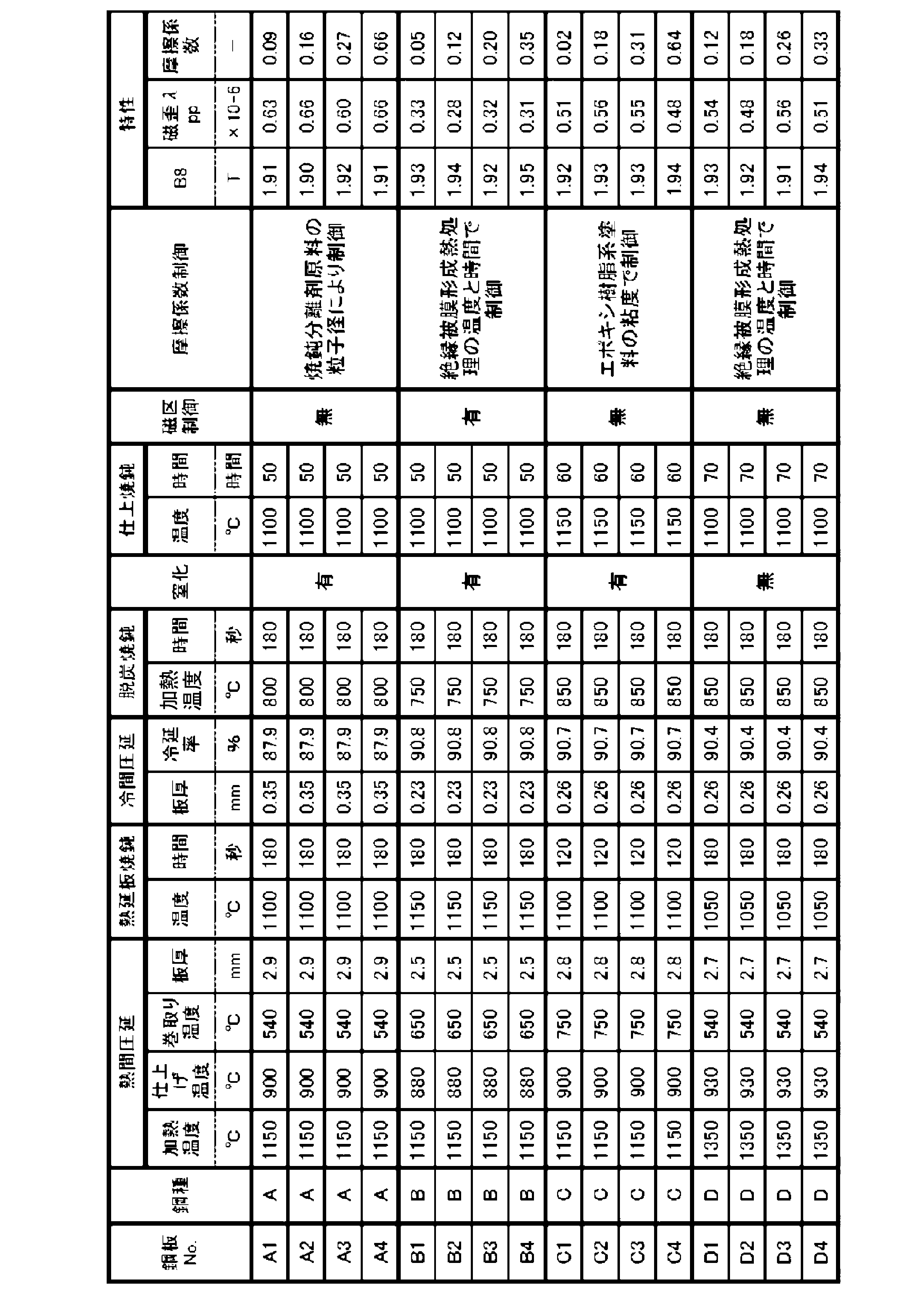

各鋼板を素材として、表5および図7に示す形状を有する巻鉄心a~eを製造した。
なお、L1はX軸方向に平行で、中心CLを含む平断面での巻鉄心の最内周にある互いに平行な方向性電磁鋼板1間の距離(内面側平面部間距離)である。なお、平面部は屈曲部以外の直線の部分をいう。L2はZ軸方向に平行で、中心CLを含む縦断面での巻鉄心の最内周にある互いに平行な方向性電磁鋼板1間の距離(内面側平面部間距離)である。L3はX軸方向に平行で、中心CLを含む平断面での巻鉄心の積層厚さ(積層方向の厚さ)である。L4はX軸方向に平行で、中心CLを含む平断面での巻鉄心の積層鋼板幅である。L5は巻鉄心の最内部の互いに隣り合って、かつ、合わせて直角を為すように配置された平面部間距離(屈曲部間の距離)である。言い換えるとL5は最内周の方向性電磁鋼板の平面部4,4aのうち、最も長さが短い平面部4aの長手方向の長さ)である。rは巻鉄心の内面側の屈曲部の曲率半径、φは巻鉄心の屈曲部の曲げ角度である。略矩形状の鉄心a~eは、内面側平面部間距離がL1である平面部が距離L1のほぼ中央で分割されており、「略Uの字」の形状を有する2つの鉄心を結合した構造となっている。ここで、コアNo.eの鉄心は、従来から一般的な巻鉄心として利用されている、鋼板をせん断した後、筒状に巻き取った後、筒状積層体のままコーナー部を一定曲率になるようにプレスし、略矩形に形成した後、焼鈍することにより形状保持を行う方法により製造された鉄心である。このため、屈曲部の曲率半径は鋼板の積層位置により大きく変動する。表5のrは最内面でのrである。rは外側に従って増加し、最外周部では約70mmとなっている。 (Iron core)
Using each steel plate as a material, wound iron cores a to e having the shapes shown in Table 5 and FIG. 7 were manufactured.
It should be noted that L1 is the distance between the grain-oriented
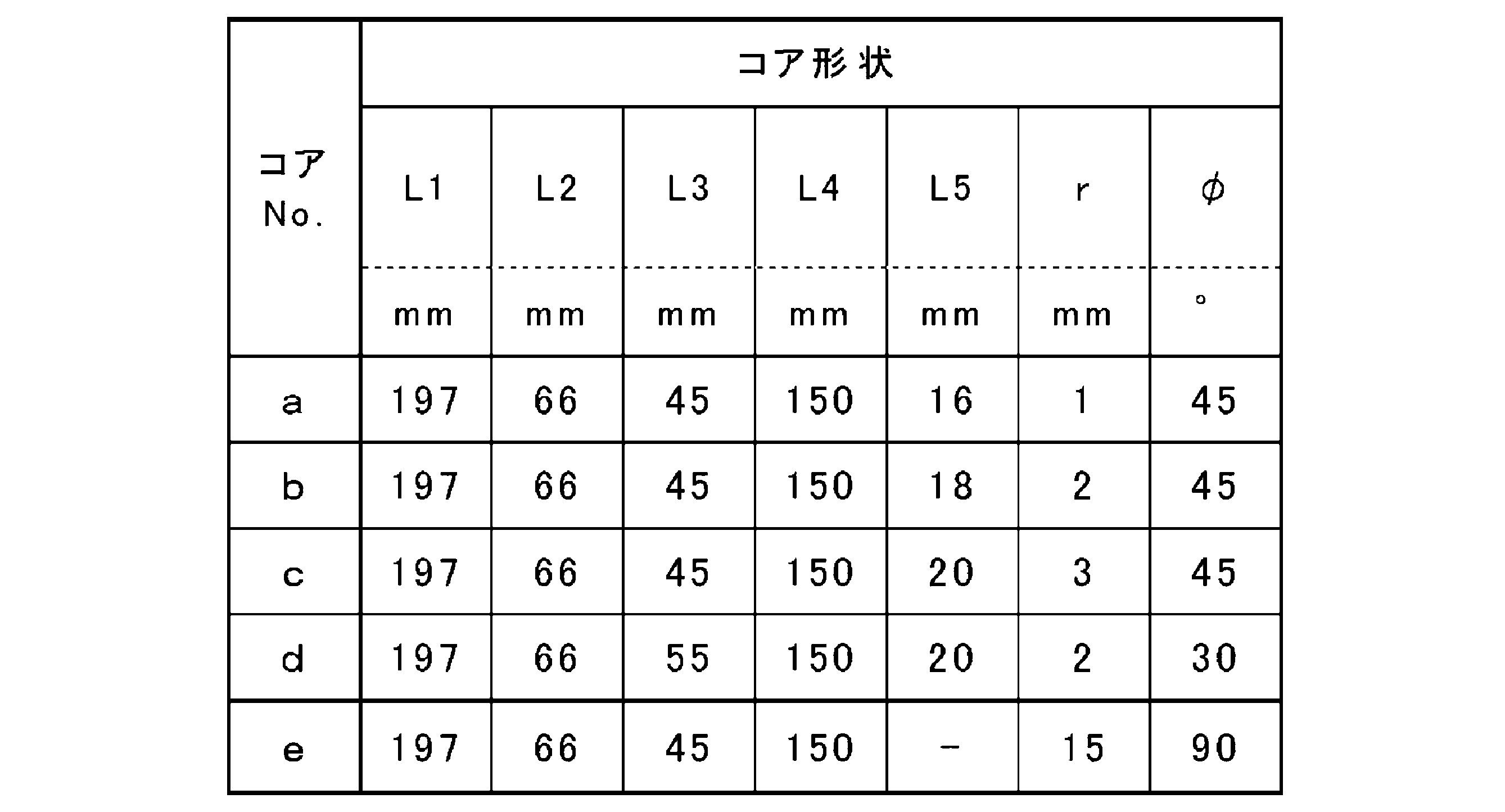
(1)方向性電磁鋼板の磁気特性
方向性電磁鋼板の磁気特性は、JIS C 2556:2015に規定された単板磁気特性試験法(Single Sheet Tester:SST)に基づいて測定した。各特性は、製造されたコイルから巻き出された帯状の電磁鋼板の長手5カ所(全長の1/10、3/10、5/10、7/10、9/10の位置)、それぞれの位置において幅4カ所(幅の1/5、2/5、3/5、4/5の位置)の計20点について測定し、その平均値を鋼板の特性とした。また、磁歪λppについては20点の測定値より標準偏差を求めた。
なお、測定される電磁鋼板は、その幅が前記単板磁気特性試験法(SST)で使用される単板(電磁鋼板)の幅と同等か広いものを使用する。 (Evaluation methods)
(1) Magnetic properties of grain-oriented electrical steel sheets The magnetic properties of grain-oriented electrical steel sheets were measured based on the single sheet magnetic property test method (Single Sheet Tester: SST) specified in JIS C 2556: 2015. Each characteristic has 5 positions of the length of the strip-shaped electromagnetic steel sheet unwound from the manufactured coil (1/10 of the total length, 3/10, 5/10, 7/10, 9/10 positions). A total of 20 points were measured at 4 width points (1/5, 2/5, 3/5, 4/5 positions of the width), and the average value was taken as the characteristic of the steel sheet. For the magnetostriction λpp, the standard deviation was obtained from the measured values at 20 points.
As the measured electromagnetic steel sheet, a steel sheet having a width equal to or wider than the width of the veneer (electrical steel sheet) used in the single plate magnetic property test method (SST) is used.
方向性電磁鋼板の層間摩擦係数は、基本的には前述の鉄心に積層されている方向性電磁鋼板の層間摩擦係数と同様に求めた。ただしサンプルの採取については以下のように実施した。まず上記20カ所(20点)から幅方向長さ50mm、圧延方向長さ350mmで20枚の鋼板を切り出し、その中から任意に18枚を選択し、さらにこれを3枚ずつ6組に分けた。各組について1枚を引き抜き用サンプルとし、残り2枚は圧延方向サイズを100mmに調整して挟み込み用サンプルとした。引き抜き用サンプルの圧延方向の端部50mmをつかみ部とし、つかみ部に隣接する部分を挟み込み用サンプルで挟み、挟み込み用サンプルに均一に1.96Nの荷重を負荷した。この状態で引き抜き用サンプルの引き抜くことで、約200mmに亘る引き抜き荷重の変化を測定した。そして接触面間の相対的なずれが開始する際の引き抜き力の変化を無視し、相対的なずれを開始した後の30~90mmまでの60mmの引き抜き距離における引き抜き荷重の平均値を1組の試験における引き抜き荷重として各組について層間摩擦係数を得た。さらに6組についての層間摩擦係数の平均値を方向性電磁鋼板の層間摩擦係数とした。 (2) Interlayer friction coefficient of grain-oriented electrical steel sheet (material) The inter-story friction coefficient of the grain-oriented electrical steel sheet was basically obtained in the same manner as the interlayer friction coefficient of the grain-oriented electrical steel sheet laminated on the above-mentioned iron core. However, the sample was collected as follows. First, 20 steel sheets were cut out from the above 20 locations (20 points) with a width direction length of 50 mm and a rolling direction length of 350 mm, 18 sheets were arbitrarily selected from them, and these were further divided into 6 sets of 3 sheets each. .. For each set, one sheet was used as a sampling sample, and the remaining two sheets were used as sandwiching samples by adjusting the rolling direction size to 100 mm. The end 50 mm in the rolling direction of the drawing sample was used as the gripping portion, and the portion adjacent to the gripping portion was sandwiched between the sandwiching samples, and a load of 1.96 N was uniformly applied to the sandwiching sample. By pulling out the drawing sample in this state, the change in the pulling load over about 200 mm was measured. Then, ignoring the change in the pulling force when the relative displacement between the contact surfaces starts, the average value of the pulling load at the pulling distance of 60 mm from 30 to 90 mm after the start of the relative displacement is set. The inter-story friction coefficient was obtained for each set as the pull-out load in the test. Further, the average value of the inter-story friction coefficient for 6 sets was taken as the inter-story friction coefficient of the grain-oriented electrical steel sheet.
(3)鉄心の騒音特性
各鉄心について騒音測定時のマイクの数およびマイクの配置、マイクと鉄心との距離等を規定したIEC60076-10の方法に基づいて騒音を測定した。 As magnetic characteristics, the magnetic flux density B8 (T) in the rolling direction of the steel sheet when excited at 800 A / m, and the Peak to Peak value of the magnetostriction measured at AC frequency: 50 Hz and exciting magnetic flux density: 1.7 T are measured. bottom.
(3) Noise characteristics of the iron core Noise was measured for each iron core based on the method of IEC60036-10 which regulated the number of microphones and the arrangement of microphones at the time of noise measurement, the distance between the microphones and the iron core, and the like.
鉄心において積層されている方向性電磁鋼板の層間摩擦係数は、以下のように求めた。鉄心を分解し、積層された鋼板から任意に積層順のままの3枚を1組として10組を選択し、上記内面側平面部間距離がL1である平面部より、幅方向中央部から幅80mm、圧延方向長さ90mm、計60枚の鋼板を切り出す。さらに各組について積層中央の1枚を引き抜き用サンプルとし、残り2枚は圧延方向長さを10mmに調整して挟み込み用サンプルとした。引き抜き用サンプルの圧延方向の端部20mmをつかみ部とし、つかみ部に隣接する部分を挟み込み用サンプルで挟み、挟み込み用サンプルに均一に1.96Nの荷重を負荷した。この状態で引き抜き用サンプルの引き抜くことで、約60mmに亘る引き抜き荷重の変化を測定した。そして接触面間の相対的なずれが開始する際の引き抜き力の変化を無視し、相対的なずれを開始した後の10~50mまでの40mmの引き抜き距離における引き抜き荷重の平均値を1組の試験における引き抜き荷重として各組について層間摩擦係数を得た。さらに10組についての層間摩擦係数の平均値を鉄心において積層されている方向性電磁鋼板の層間摩擦係数とした。また、各鉄心において10個の測定値のうち0.20~0.70の範囲内であった測定値の個数を得る。
(5)鉄心において積層されている方向性電磁鋼板の磁歪λppおよびその標準偏差
鉄心において積層されている方向性電磁鋼板の磁歪λppの標準偏差は、以下のように求めた。鉄心を分解し、積層された鋼板から任意に20枚の鋼板を選択し、その平面部を切り出しサンプルとする。このサンプルで、交流周波数:50Hz、励磁磁束密度:1.7Tでの磁歪のPeak to Peak値を測定した。20枚の平均値を鉄心において積層されている方向性電磁鋼板の磁歪λppとするとともに、その標準偏差を求めた。 (4) Interlayer friction coefficient of grain-oriented electrical steel sheets laminated on the iron core The inter-story friction coefficient of the grain-oriented electrical steel sheets laminated on the iron core was determined as follows. The iron core is disassembled, and 10 sets are selected from the laminated steel plates, with 3 sheets in the order of stacking as one set. A total of 60 steel plates with a length of 80 mm and a length in the rolling direction of 90 mm are cut out. Further, for each set, one in the center of the stack was used as a sample for drawing, and the remaining two were used as samples for sandwiching by adjusting the length in the rolling direction to 10 mm. The end 20 mm in the rolling direction of the drawing sample was used as the gripping portion, and the portion adjacent to the gripping portion was sandwiched between the sandwiching samples, and a load of 1.96 N was uniformly applied to the sandwiching sample. By pulling out the drawing sample in this state, the change in the pulling load over about 60 mm was measured. Then, ignoring the change in the pulling force when the relative displacement between the contact surfaces starts, the average value of the pulling load at the pulling distance of 40 mm from 10 to 50 m after the start of the relative displacement is set. The inter-story friction coefficient was obtained for each set as the pull-out load in the test. Further, the average value of the inter-story friction coefficient for 10 sets was taken as the inter-story friction coefficient of the grain-oriented electrical steel sheets laminated on the iron core. Further, the number of measured values in the range of 0.20 to 0.70 out of 10 measured values is obtained for each iron core.
(5) Magnetostriction λpp of the grain-oriented electrical steel sheet laminated on the iron core and its standard deviation The standard deviation of the magnetostriction λpp of the grain-oriented electrical steel sheet laminated on the iron core was calculated as follows. The iron core is disassembled, 20 steel plates are arbitrarily selected from the laminated steel plates, and the flat surface portion thereof is used as a sample. In this sample, the peak to peak value of magnetostriction at an AC frequency of 50 Hz and an exciting magnetic flux density of 1.7 T was measured. The average value of the 20 sheets was taken as the magnetostriction λpp of the grain-oriented electrical steel sheets laminated on the iron core, and the standard deviation thereof was obtained.
層間摩擦係数が異なる各種鋼板を用いて製造した各種鉄心における騒音を評価した。また各鉄心を分解して積層されている方向性電磁鋼板の層間摩擦係数を求めた。結果を表6に示す。同じ鋼種でほぼ同じ磁歪λppである素材を用いた場合であっても、層間摩擦係数を適切に制御することにより鉄心の低騒音化が達成できることがわかる。
また、表6には、鉄心形状が本発明範囲内にある場合に騒音に大きな差がみられた層間摩擦係数が大きく異なる鋼板を素材として、屈曲部の曲率半径が大きな鉄心(コアNo.e)を製造した例(試験No.1-25~1-28)を示している。コアNo.eの鉄心は、従来から一般的な巻鉄心として利用されている鋼板を筒状に巻き取った後、筒状積層体のままコーナー部を一定曲率になるようにプレスし、略矩形に形成した後、焼鈍することにより歪取りと形状保持を行う方法により製造された鉄心である。本事例では、700℃で2時間の歪取り焼鈍を実施している。表では鉄心を分解して得られた鋼板特性値は「-」としているが、これはコアNo.eの鉄心では上記製造過程における歪の付与および熱処理により分解して得られる鋼板の形状が良好でなく妥当な特性値が得られなかったためである。これらの事例では最終的な歪取り焼鈍により騒音自体は小さくなってはいるものの、少なくとも素材鋼板の層間摩擦係数を大きく変化させたとしても、本発明のような効果は期待できないことがわかる。 (Example 1)
Noise in various iron cores manufactured using various steel sheets with different interlaminar friction coefficients was evaluated. In addition, the inter-story friction coefficient of the grain-oriented electrical steel sheets laminated by disassembling each core was obtained. The results are shown in Table 6. It can be seen that noise reduction of the iron core can be achieved by appropriately controlling the interlaminar friction coefficient even when materials of the same steel type and substantially the same magnetostriction λpp are used.
Further, in Table 6, when the shape of the core is within the range of the present invention, a steel plate having a large difference in noise and a large difference in the coefficient of friction between layers is used as a material, and the core (core No. e) having a large radius of curvature of the bent portion is used as a material. ) Is manufactured (Test Nos. 1-25 to 1-28). Core No. The iron core of e was formed into a substantially rectangular shape by winding a steel plate, which has been conventionally used as a general wound core, into a cylindrical shape, and then pressing the corners of the tubular laminated body so as to have a constant curvature. After that, it is an iron core manufactured by a method of removing strain and maintaining its shape by annealing. In this case, strain removal annealing is performed at 700 ° C. for 2 hours. In the table, the steel sheet characteristic value obtained by decomposing the iron core is "-", but this is the core No. This is because, in the iron core of e, the shape of the steel sheet obtained by applying strain in the above-mentioned manufacturing process and disassembling by heat treatment was not good, and appropriate characteristic values could not be obtained. In these cases, the noise itself is reduced by the final strain removal annealing, but it can be seen that the effect as in the present invention cannot be expected even if the interlayer friction coefficient of the material steel sheet is changed significantly.
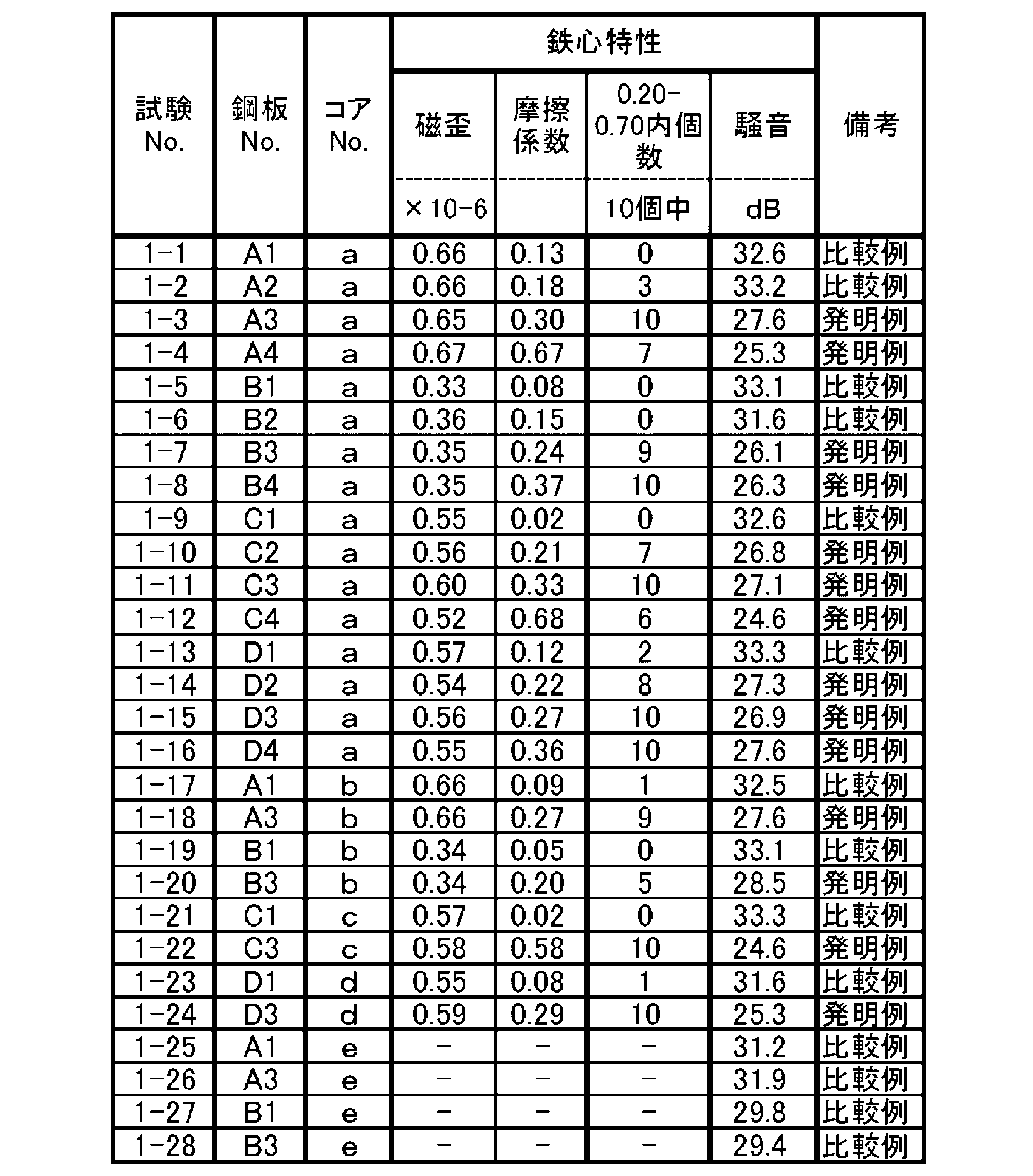
層間摩擦係数、磁歪λpp、磁歪λppの標準偏差が異なる各種鋼板を用いて製造した各種鉄心における騒音を評価した。また各鉄心を分解して積層されている方向性電磁鋼板の層間摩擦係数、磁歪λpp、磁歪λppの標準偏差を求めた。結果を表7に示す。層間摩擦係数に加え、磁歪λppの標準偏差の適正化により鉄心の低騒音化が達成できることがわかる。 (Example 2)
The noise in various iron cores manufactured using various steel sheets having different standard deviations of the inter-story friction coefficient, magnetostriction λpp, and magnetostriction λpp was evaluated. In addition, the standard deviations of the inter-story friction coefficient, magnetostriction λpp, and magnetostriction λpp of the grain-oriented electrical steel sheets laminated by disassembling each core were obtained. The results are shown in Table 7. It can be seen that the noise reduction of the iron core can be achieved by optimizing the standard deviation of the magnetostriction λpp in addition to the interlaminar friction coefficient.

2 積層構造
3 コーナー部
4 第1の平面部(平面部)
5 屈曲部
6 接合部
10 巻鉄心本体 1
5 Bending
Claims (3)
- 側面視において略矩形状の巻鉄心本体を備える巻鉄心であって、
前記巻鉄心本体は、長手方向に平面部とコーナー部とが交互に連続し、当該各コーナー部を挟んで隣り合う2つの平面部のなす角が90°である方向性電磁鋼板が、板厚方向に積み重ねられた部分を含み、側面視において略矩形状の積層構造を有し、
前記各コーナー部は、前記方向性電磁鋼板の側面視において、曲線状の形状を有する屈曲部を2つ以上有しており、且つ、一つのコーナー部に存在する各屈曲部それぞれの曲げ角度の合計が90°であり、
前記各屈曲部の側面視における内面側曲率半径rは1mm以上5mm以下であり、
前記方向性電磁鋼板が
質量%で、
Si:2.0~7.0%、
を含有し、残部がFeおよび不純物からなる化学組成を有し、
Goss方位に配向する集合組織を有し、且つ
少なくとも前記平面部の一部において、積層される前記方向性電磁鋼板の動摩擦係数である層間摩擦係数について、異なる複数の積層厚さ位置で得られる測定値の半数以上が0.20~0.70であり、かつその平均値が0.20~0.70であることを特徴とする、巻鉄心。 A wound core having a substantially rectangular wound core body when viewed from the side.
The core body is a grain-oriented electrical steel sheet in which flat surfaces and corners are alternately continuous in the longitudinal direction, and the angle formed by two adjacent flat surfaces sandwiching each corner is 90 °. It has a substantially rectangular laminated structure in the side view, including the parts stacked in the direction.
Each of the corners has two or more bent portions having a curved shape in the side view of the grain-oriented electrical steel sheet, and the bending angle of each bent portion existing in one corner. The total is 90 °,
The radius of curvature r on the inner surface side in the side view of each of the bent portions is 1 mm or more and 5 mm or less.
The grain-oriented electrical steel sheet is by mass%,
Si: 2.0-7.0%,
Has a chemical composition in which the balance consists of Fe and impurities.
Measurements obtained at a plurality of different laminated thickness positions with respect to the inter-story friction coefficient, which is the dynamic friction coefficient of the directional electromagnetic steel plate to be laminated, at least in a part of the flat surface portion having an aggregate structure oriented in the Goss direction. A wound iron core characterized in that more than half of the values are 0.20 to 0.70, and the average value thereof is 0.20 to 0.70. - 積層された前記方向性電磁鋼板から任意に複数枚を抜き出した各方向性電磁鋼板の前記平面部で測定された磁歪のPeak to Peak値により決定した、前記方向性電磁鋼板の磁歪λppの標準偏差が、0.01×10⁻⁶~0.10×10⁻⁶であることを特徴とする、請求項1に記載の巻鉄心。 The standard deviation of the magnetostriction λpp of the grain-oriented electrical steel sheet determined by the Peak to Peak value of the magnetostriction measured at the plane portion of each grain-oriented electrical steel sheet obtained by arbitrarily extracting a plurality of sheets from the laminated grain-oriented electrical steel sheet. The wound steel core according to claim 1, wherein the product is 0.01 × 10 -6 to 0.10 × 10 -6 .
- 前記平面部において、前記巻鉄心の内面側からの前記方向性電磁鋼板の積層厚さの50%以内の領域において、積層される前記方向性電磁鋼板の前記層間摩擦係数が0.20~0.70であることを特徴とする、請求項1又は2に記載の巻鉄心。 In the flat portion, the inter-story friction coefficient of the grain-oriented electrical steel sheets to be laminated is 0.20 to 0. In the region within 50% of the laminated thickness of the grain-oriented electrical steel sheets from the inner surface side of the wound steel core. The wound steel core according to claim 1 or 2, characterized in that it is 70.
Priority Applications (7)
| Application Number | Priority Date | Filing Date | Title |
|---|---|---|---|
| CN202180072385.0A CN116348620A (en) | 2020-10-26 | 2021-10-26 | Coiled iron core |
| JP2022526715A JP7103555B1 (en) | 2020-10-26 | 2021-10-26 | Winding iron core |
| US18/033,110 US20230395293A1 (en) | 2020-10-26 | 2021-10-26 | Wound core |
| AU2021370592A AU2021370592A1 (en) | 2020-10-26 | 2021-10-26 | Wound core |
| EP21886213.4A EP4235711A4 (en) | 2020-10-26 | 2021-10-26 | Wound core |
| CA3195981A CA3195981A1 (en) | 2020-10-26 | 2021-10-26 | Wound core |
| KR1020237013632A KR20230071169A (en) | 2020-10-26 | 2021-10-26 | Cheol Shim Kwon |
Applications Claiming Priority (2)
| Application Number | Priority Date | Filing Date | Title |
|---|---|---|---|
| JP2020178891 | 2020-10-26 | ||
| JP2020-178891 | 2020-10-26 |
Publications (1)
| Publication Number | Publication Date |
|---|---|
| WO2022092095A1 true WO2022092095A1 (en) | 2022-05-05 |
Family
ID=81383922
Family Applications (1)
| Application Number | Title | Priority Date | Filing Date |
|---|---|---|---|
| PCT/JP2021/039518 WO2022092095A1 (en) | 2020-10-26 | 2021-10-26 | Wound core |
Country Status (9)
| Country | Link |
|---|---|
| US (1) | US20230395293A1 (en) |
| EP (1) | EP4235711A4 (en) |
| JP (1) | JP7103555B1 (en) |
| KR (1) | KR20230071169A (en) |
| CN (1) | CN116348620A (en) |
| AU (1) | AU2021370592A1 (en) |
| CA (1) | CA3195981A1 (en) |
| TW (1) | TWI777830B (en) |
| WO (1) | WO2022092095A1 (en) |
Cited By (1)
| Publication number | Priority date | Publication date | Assignee | Title |
|---|---|---|---|---|
| WO2023249052A1 (en) * | 2022-06-22 | 2023-12-28 | 日本製鉄株式会社 | Wound core |
Citations (12)
| Publication number | Priority date | Publication date | Assignee | Title |
|---|---|---|---|---|
| JPH11124685A (en) | 1997-10-21 | 1999-05-11 | Kawasaki Steel Corp | Magnetic shielding material and its production |
| JP2001192785A (en) | 2000-01-06 | 2001-07-17 | Kawasaki Steel Corp | Grain oriented silicon steel sheet excellent in magnetic property, and its manufacturing method |
| JP2005240079A (en) | 2004-02-25 | 2005-09-08 | Jfe Steel Kk | Grain oriented silicon steel sheet low in iron loss deterioration ratio |
| JP2005286169A (en) | 2004-03-30 | 2005-10-13 | Toshiba Corp | Manufacturing method and apparatus of wound core for transformer |
| JP2011090456A (en) | 2009-10-21 | 2011-05-06 | Jfe Steel Corp | Order receiving and shipping method for grain oriented magnetic steel sheet for transformer |
| JP2011246770A (en) * | 2010-05-27 | 2011-12-08 | Nippon Steel Corp | Grain oriented magnetic steel sheet and tension insulating film coated grain oriented magnetic steel sheet |
| JP2012052229A (en) | 2010-08-06 | 2012-03-15 | Jfe Steel Corp | Grain-oriented electromagnetic steel sheet and process for producing the same |
| AU2012337260A1 (en) | 2011-11-14 | 2014-05-22 | Hitachi Energy Ltd | Wind-on core manufacturing method for split core configurations |
| JP6224468B2 (en) | 2014-01-27 | 2017-11-01 | 東芝産業機器システム株式会社 | Wrapped iron core and method for manufacturing the wound iron core |
| WO2018123339A1 (en) | 2016-12-28 | 2018-07-05 | Jfeスチール株式会社 | Grain-oriented electrical steel sheet, transformer core, transformer, and method for reducing transformer noise |
| JP2018148036A (en) | 2017-03-06 | 2018-09-20 | 新日鐵住金株式会社 | Wound core |
| JP2020178891A (en) | 2019-04-25 | 2020-11-05 | キョーラク株式会社 | Container opening tool |
Family Cites Families (4)
| Publication number | Priority date | Publication date | Assignee | Title |
|---|---|---|---|---|
| US4197233A (en) | 1978-03-15 | 1980-04-08 | Kennecott Copper Corporation | Anti-fouling and anti-sliming coating material |
| JPH02260619A (en) * | 1989-03-31 | 1990-10-23 | Nippon Steel Corp | Manufacture of electromagnetic core |
| JP2861702B2 (en) * | 1993-01-19 | 1999-02-24 | 日本鋼管株式会社 | Grain-oriented electrical steel sheet having an insulating film excellent in workability and heat resistance, and method for producing the same |
| TWI667672B (en) * | 2017-01-10 | 2019-08-01 | 日商日本製鐵股份有限公司 | Winding iron core and manufacturing method thereof |
-
2021
- 2021-10-26 CA CA3195981A patent/CA3195981A1/en active Pending
- 2021-10-26 WO PCT/JP2021/039518 patent/WO2022092095A1/en active Application Filing
- 2021-10-26 JP JP2022526715A patent/JP7103555B1/en active Active
- 2021-10-26 AU AU2021370592A patent/AU2021370592A1/en active Pending
- 2021-10-26 US US18/033,110 patent/US20230395293A1/en active Pending
- 2021-10-26 CN CN202180072385.0A patent/CN116348620A/en active Pending
- 2021-10-26 TW TW110139644A patent/TWI777830B/en active
- 2021-10-26 EP EP21886213.4A patent/EP4235711A4/en active Pending
- 2021-10-26 KR KR1020237013632A patent/KR20230071169A/en unknown
Patent Citations (12)
| Publication number | Priority date | Publication date | Assignee | Title |
|---|---|---|---|---|
| JPH11124685A (en) | 1997-10-21 | 1999-05-11 | Kawasaki Steel Corp | Magnetic shielding material and its production |
| JP2001192785A (en) | 2000-01-06 | 2001-07-17 | Kawasaki Steel Corp | Grain oriented silicon steel sheet excellent in magnetic property, and its manufacturing method |
| JP2005240079A (en) | 2004-02-25 | 2005-09-08 | Jfe Steel Kk | Grain oriented silicon steel sheet low in iron loss deterioration ratio |
| JP2005286169A (en) | 2004-03-30 | 2005-10-13 | Toshiba Corp | Manufacturing method and apparatus of wound core for transformer |
| JP2011090456A (en) | 2009-10-21 | 2011-05-06 | Jfe Steel Corp | Order receiving and shipping method for grain oriented magnetic steel sheet for transformer |
| JP2011246770A (en) * | 2010-05-27 | 2011-12-08 | Nippon Steel Corp | Grain oriented magnetic steel sheet and tension insulating film coated grain oriented magnetic steel sheet |
| JP2012052229A (en) | 2010-08-06 | 2012-03-15 | Jfe Steel Corp | Grain-oriented electromagnetic steel sheet and process for producing the same |
| AU2012337260A1 (en) | 2011-11-14 | 2014-05-22 | Hitachi Energy Ltd | Wind-on core manufacturing method for split core configurations |
| JP6224468B2 (en) | 2014-01-27 | 2017-11-01 | 東芝産業機器システム株式会社 | Wrapped iron core and method for manufacturing the wound iron core |
| WO2018123339A1 (en) | 2016-12-28 | 2018-07-05 | Jfeスチール株式会社 | Grain-oriented electrical steel sheet, transformer core, transformer, and method for reducing transformer noise |
| JP2018148036A (en) | 2017-03-06 | 2018-09-20 | 新日鐵住金株式会社 | Wound core |
| JP2020178891A (en) | 2019-04-25 | 2020-11-05 | キョーラク株式会社 | Container opening tool |
Non-Patent Citations (1)
| Title |
|---|
| See also references of EP4235711A4 |
Cited By (1)
| Publication number | Priority date | Publication date | Assignee | Title |
|---|---|---|---|---|
| WO2023249052A1 (en) * | 2022-06-22 | 2023-12-28 | 日本製鉄株式会社 | Wound core |
Also Published As
| Publication number | Publication date |
|---|---|
| US20230395293A1 (en) | 2023-12-07 |
| JP7103555B1 (en) | 2022-07-20 |
| AU2021370592A1 (en) | 2023-06-08 |
| EP4235711A1 (en) | 2023-08-30 |
| KR20230071169A (en) | 2023-05-23 |
| TW202316461A (en) | 2023-04-16 |
| JPWO2022092095A1 (en) | 2022-05-05 |
| TWI777830B (en) | 2022-09-11 |
| CA3195981A1 (en) | 2022-05-05 |
| CN116348620A (en) | 2023-06-27 |
| EP4235711A4 (en) | 2024-05-01 |
Similar Documents
| Publication | Publication Date | Title |
|---|---|---|
| JP6776952B2 (en) | Winding iron core | |
| WO2012017670A1 (en) | Grain-oriented magnetic steel sheet and process for producing same | |
| JP6794888B2 (en) | Selection method of grain-oriented electrical steel sheets and manufacturing method of wound steel cores | |
| WO2022092095A1 (en) | Wound core | |
| JP7103553B1 (en) | Winding iron core | |
| WO2022092117A1 (en) | Wound core, method for manufacturing wound core, and wound core manufacturing device | |
| JP5565307B2 (en) | Method for producing grain-oriented electrical steel sheet | |
| RU2809519C1 (en) | Tape core | |
| JP7188662B2 (en) | Wound iron core | |
| WO2022092114A1 (en) | Wound core | |
| WO2022092120A1 (en) | Wound core | |
| JP2022069937A (en) | Winding iron core | |
| JP7485954B2 (en) | Wound core | |
| JP7151946B1 (en) | Wound core and method for manufacturing wound core | |
| WO2023007952A1 (en) | Wound core and wound core manufacturing method | |
| JP7151947B1 (en) | Wound core and method for manufacturing wound core | |
| WO2022092118A1 (en) | Wound core | |
| WO2023007953A1 (en) | Wound core and wound core manufacturing method | |
| WO2022092121A1 (en) | Method and device for manufacturing wound iron core | |
| WO2022092096A1 (en) | Winding iron core, method for manufacturing winding iron core, and winding iron core manufacturing apparatus | |
| WO2023167015A1 (en) | Three-phased three-legged wound core and method for manufacturing same | |
| JP2022069940A (en) | Winding iron core | |
| JP2022070245A (en) | Winding iron core and method for manufacturing winding iron core | |
| JP2022070241A (en) | Winding iron core | |
| JP2022069944A (en) | Manufacturing method and manufacturing device for iron core |
Legal Events
| Date | Code | Title | Description |
|---|---|---|---|
| ENP | Entry into the national phase |
Ref document number: 2022526715 Country of ref document: JP Kind code of ref document: A |
|
| 121 | Ep: the epo has been informed by wipo that ep was designated in this application |
Ref document number: 21886213 Country of ref document: EP Kind code of ref document: A1 |
|
| ENP | Entry into the national phase |
Ref document number: 3195981 Country of ref document: CA |
|
| ENP | Entry into the national phase |
Ref document number: 20237013632 Country of ref document: KR Kind code of ref document: A |
|
| WWE | Wipo information: entry into national phase |
Ref document number: 18033110 Country of ref document: US |
|
| REG | Reference to national code |
Ref country code: BR Ref legal event code: B01A Ref document number: 112023007588 Country of ref document: BR |
|
| NENP | Non-entry into the national phase |
Ref country code: DE |
|
| ENP | Entry into the national phase |
Ref document number: 2021886213 Country of ref document: EP Effective date: 20230526 |
|
| ENP | Entry into the national phase |
Ref document number: 2021370592 Country of ref document: AU Date of ref document: 20211026 Kind code of ref document: A |
|
| ENP | Entry into the national phase |
Ref document number: 112023007588 Country of ref document: BR Kind code of ref document: A2 Effective date: 20230420 |