WO2022091895A1 - ロボット制御方法 - Google Patents
ロボット制御方法 Download PDFInfo
- Publication number
- WO2022091895A1 WO2022091895A1 PCT/JP2021/038697 JP2021038697W WO2022091895A1 WO 2022091895 A1 WO2022091895 A1 WO 2022091895A1 JP 2021038697 W JP2021038697 W JP 2021038697W WO 2022091895 A1 WO2022091895 A1 WO 2022091895A1
- Authority
- WO
- WIPO (PCT)
- Prior art keywords
- information
- robot
- work
- control
- sensor
- Prior art date
- Legal status (The legal status is an assumption and is not a legal conclusion. Google has not performed a legal analysis and makes no representation as to the accuracy of the status listed.)
- Ceased
Links
Images







Classifications
-
- B—PERFORMING OPERATIONS; TRANSPORTING
- B25—HAND TOOLS; PORTABLE POWER-DRIVEN TOOLS; MANIPULATORS
- B25J—MANIPULATORS; CHAMBERS PROVIDED WITH MANIPULATION DEVICES
- B25J9/00—Program-controlled manipulators
- B25J9/16—Program controls
- B25J9/1694—Program controls characterised by use of sensors other than normal servo-feedback from position, speed or acceleration sensors, perception control, multi-sensor controlled systems, sensor fusion
- B25J9/1697—Vision controlled systems
-
- B—PERFORMING OPERATIONS; TRANSPORTING
- B25—HAND TOOLS; PORTABLE POWER-DRIVEN TOOLS; MANIPULATORS
- B25J—MANIPULATORS; CHAMBERS PROVIDED WITH MANIPULATION DEVICES
- B25J9/00—Program-controlled manipulators
- B25J9/16—Program controls
- B25J9/1628—Program controls characterised by the control loop
- B25J9/1653—Program controls characterised by the control loop parameters identification, estimation, stiffness, accuracy, error analysis
-
- G—PHYSICS
- G05—CONTROLLING; REGULATING
- G05B—CONTROL OR REGULATING SYSTEMS IN GENERAL; FUNCTIONAL ELEMENTS OF SUCH SYSTEMS; MONITORING OR TESTING ARRANGEMENTS FOR SUCH SYSTEMS OR ELEMENTS
- G05B2219/00—Program-control systems
- G05B2219/30—Nc systems
- G05B2219/40—Robotics, robotics mapping to robotics vision
- G05B2219/40557—Tracking a tool, compute 3-D position relative to camera
-
- G—PHYSICS
- G05—CONTROLLING; REGULATING
- G05B—CONTROL OR REGULATING SYSTEMS IN GENERAL; FUNCTIONAL ELEMENTS OF SUCH SYSTEMS; MONITORING OR TESTING ARRANGEMENTS FOR SUCH SYSTEMS OR ELEMENTS
- G05B2219/00—Program-control systems
- G05B2219/30—Nc systems
- G05B2219/40—Robotics, robotics mapping to robotics vision
- G05B2219/40584—Camera, non-contact sensor mounted on wrist, indep from gripper
Definitions
- This disclosure relates to a robot control method for performing work using a sensor mounted on a robot.
- Patent Document 1 discloses a visual recognition device for controlling position and orientation based on image data taken by a camera.
- a position where the work object cannot be recognized is detected in advance by controlling the position and posture by the visual servo, and the position is set as a prohibited area.
- the position is set as a prohibited area.
- the robot control method is a robot control method in a control device connected to a robot that works on a work object and a sensor mounted on the robot.
- environment information indicating the environment around the robot is calculated based on a plurality of environment sensor information acquired by using sensors from a plurality of positions and angles of the environment around the robot.
- the robot uses the sensor to acquire the first sensor information, and the robot sets the work target based on the target work information indicating the work target for the robot's work object, the environmental information, and the first sensor information.
- the first step of calculating the approaching first control information and transmitting the first control information to the robot is executed.
- the sensor is used to acquire the second sensor information, and based on the target work information and the second sensor information, the second control information that causes the robot to approach the work target is calculated. Then, the second step of transmitting the second control information to the robot is executed.
- the robot control method is a robot control method in a control device connected to a robot that works on a work object and a sensor mounted on the robot.
- environment information indicating the environment around the robot is calculated based on a plurality of environment sensor information acquired by using sensors from a plurality of positions and angles of the environment around the robot.
- the robot uses the sensor to acquire the first sensor information, and the robot sets the work target based on the target work information indicating the work target for the robot's work object, the environmental information, and the first sensor information.
- the first step of calculating the approaching first control information is performed.
- the third step of calculating the third control information based on the first control information and the second control information and transmitting the third control information to the robot is executed.
- the work can be executed while ensuring the accuracy.
- Schematic diagram showing environmental image information in the first embodiment Schematic diagram showing environmental information of the robot in the first embodiment
- Schematic diagram showing the target state of the robot in the first embodiment Schematic diagram showing the target captured image in the first embodiment
- Schematic diagram showing the first target image information in the first embodiment Schematic diagram showing the second target image information in the first embodiment
- the flowchart which shows the control operation of the robot in Embodiment 1. Schematic diagram showing an image captured by a camera in the initial state of the robot according to the first embodiment.
- a robot that performs work on behalf of a human is controlled by a control device to perform work such as picking and placing a work object.
- feedback control using the information acquired from the sensor is performed in order to perform precise control adapted to the environment.
- the control device controls the robot based on the sensor information acquired from the sensor. In this way, by using the sensor, the robot can perform work adapted to the environment.
- the sensor information does not always include information on the work object.
- the work object is shown in the captured image acquired from the camera.
- the robot cannot be controlled based on the captured image. For example, when gripping a work object, the gripping position of the work object is determined by recognizing the work object based on the sensor information. Therefore, if the work object cannot be recognized, the gripping position cannot be determined and the work cannot be executed.
- control is executed using not only the information of the work object but also the information of the workbench (object existing in the environment around the robot). As a result, even when the work object does not exist in the sensor information, the work can be executed while ensuring the accuracy.
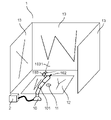
- FIG. 1 is a system configuration diagram showing a configuration of a robot control system according to the first embodiment.
- the control system 1 in the first embodiment includes at least a robot 10, a control device 2, a screw hole 11 which is a work object, and a substrate 12 and a wall 13 which are workbenches.
- the control device 2 can be connected to and communicate with the robot 10.
- the control device 2 may be built in the robot 10.
- the robot 10 includes a robot arm 101, a driver 102 as an end effector, and a camera 103 as a sensor.
- the control system 1 is not limited to the configuration shown in FIG.
- the robot arm 101 includes a mechanism having one or more joints.
- the robot arm 101 can control the position and posture of the driver 102.
- the robot arm does not necessarily have to have joints.
- the robot arm may be provided with a mechanism capable of expanding and contracting.
- the robot arm may be a robot arm that is common to the parties concerned.
- the driver 102 is an end effector capable of inserting a screw into a screw hole 11.
- the driver 102 is mounted on the tip of the robot arm 101.
- the driver 102 is attached so that the direction of the link at the tip of the robot arm 101 and the direction of the driver 102 are parallel to each other.
- the end effector is not limited to the driver 102.
- an end effector having one or more fingers may be used.
- the end effector may be a spherical flexible object that can be gripped so as to wrap the work object.
- the end effector may be one that is common to the parties concerned.
- the camera 103 is used as a kind of sensor for acquiring information on the environment around the robot 10. As shown in FIG. 1, the camera 103 acquires a captured image including the screw hole 11 (working object) or the substrate 12 and the wall 13 (workbench) by imaging the imaging range 1031.
- the camera 103 is mounted on the tip of the robot arm 101. For example, as shown in FIG. 1, the camera 103 is mounted so as to capture a portion of work by the driver 102 by attaching the driver 102 to the link to which the driver 102 is attached.
- the camera 103 may be attached to a position other than the tip of the robot arm 101. For example, by attaching it to the link at the base of the robot arm 101, the surrounding environment may be rotated to take an image.
- the camera 103 may also acquire information other than the captured image.
- the camera 103 may acquire the parameters of the camera 103.
- the camera 103 is a depth sensor and may acquire a depth image.
- the camera 103 is a three-dimensional distance sensor and may acquire depth information.
- the camera 103 may be a camera 103 that is common to the parties concerned.
- the screw hole 11 (working object) is an object to be worked on by using the robot arm 101 or the driver 102 when the robot 10 performs the work.
- the work of the robot 10 is to insert a screw into the screw hole 11 by using the driver 102.
- the board 12 and the wall 13 are places where work is performed, including objects existing in the environment around the robot 10.
- the board 12 and the wall 13 are places where work is performed, including objects existing in the environment around the robot 10.
- FIG. 1 when performing screw tightening work, there are a substrate 12 having screw holes 11 and a wall 13 surrounding the place where the work is performed around the robot 10.
- the environment is a place where work is performed, including the screw hole 11 (work object), the board 12, and the wall 13 (workbench).
- the work of the robot 10 When carrying out the work of transporting the board 12 in the control system 1, the work of the robot 10 is to grasp the board 12 and carry it to a designated place by using a two-finger hand as an end effector. At this time, the work object is the substrate 12.
- the workbench is a wall 13. As described above, even if the work is performed on the same control system 1, the work object and the workbench may differ depending on the work content.
- the workbench may include objects that are not related to the work.
- the workbench may include a ceiling.
- a desk different from the one on which the robot 10 is installed may be included in the workbench. That is, when the captured image is acquired by the camera 103, the workbench is all the objects included in the imaging range 1031.
- the robot arm 101 is a 6-axis industrial robot in which links are connected in series.
- the driver 102 is used as an end effector. However, it is assumed that the screw is attached to the tip of the driver 102.
- the camera 103 acquires an RGB image.
- the work object is a screw hole 11, and the workbench is a board 12 and a wall 13. It is assumed that the substrate 12 and the wall 13 have a pattern on which feature points can be extracted by image processing. In FIG. 1, this pattern is briefly illustrated.
- the environment is a screw hole 11, a substrate 12, and a wall 13.
- the posture of the robot 10 at the initial time faces the wall 13 as shown in FIG.
- the control device 2 executes control so that the robot 10 can execute the screw tightening operation by using the image captured by the camera.
- the posture of the robot 10 when executing the screw tightening operation that is, the target state is a state in which the posture of the driver 102 is perpendicular to the screw hole 11 and the position of the driver 102 is directly above the screw hole 11.
- a schematic diagram of the robot 10 in the target state will be described later with reference to FIG.
- the sequence diagram shows the exchange of data between the operator S1, the control device 2, the robot 10, and the camera 103.
- the operator S1 is a person who operates the robot 10. Further, as the control device 2, the robot 10, and the camera 103, those described with reference to FIG. 1 are used.
- FIG. 2 is a sequence diagram showing an operation of calculating environmental information of the robot according to the first embodiment.
- the control device 2 calculates the environmental information based on the environmental image information obtained by performing image processing on the captured image acquired from the camera 103.
- the environmental image information is image information of the environment based on the captured image captured by the camera 103.
- Environmental information is information indicating three-dimensional position information of environmental features.
- the environmental image information is an image group in which the screw hole 11, the substrate 12, and the wall 13 are imaged, and the environmental information is a three-dimensional feature of the screw hole 11, the substrate 12, and the wall 13. It is a three-dimensional point cloud indicating a position.
- the captured image is an example of sensor data
- the environmental image information is an example of environmental sensor information.
- the operator S1 transmits an instruction to acquire environmental information to the control device 2 (S001).
- the operator S1 may define and transmit the robot operation for acquiring the environmental image information to the control device 2.
- the operator S1 may dynamically transmit the control information to the control device 2 by using a programming pendant or the like. Further, the operator S1 may directly move the robot by hand. In this way, the operator S1 may interactively input control information to the control device 2 and operate the robot 10.
- control device 2 transmits control information including an operation for acquiring environmental information to the robot 10 to operate the robot 10 (S002).
- control device 2 transmits a command to acquire the environmental image information to the camera 103 (S003). It is not necessary to mount the camera 103 on the robot 10 and take an image in order to acquire the environmental image. That is, the operator S1 may have the camera 103 and acquire the captured image. The order of step S002 and step S003 may change.
- step S004 the camera 103 acquires the captured image, transmits the captured image to the control device 2, and the control device 2 stores the captured image (S004).
- step S004 while the control device 2 is moving the robot 10 in step S002, the image is captured by the camera 103. Therefore, the control device 2 receives the captured images acquired from the plurality of positions and postures of the camera 103 one by one. And remember.
- the robot 10 When the robot 10 completes the operation specified in step S002, the robot 10 transmits a signal to the control device 2 that the operation of the robot 10 is completed (S005).
- step S005 the control device 2 transmits a command to end the imaging of the camera 103 to the camera 103 (S006).
- step S006 the camera 103 ends the imaging, and the camera 103 transmits a signal to the control device 2 that the imaging is completed (S007).
- the control device 2 acquires the environment image information obtained by comprehensively photographing the environment with the camera 103.
- control device 2 calculates the environmental information based on the environmental image information acquired in step S004 (S008).
- the control device 2 stores the calculated environmental information. The method of calculating the environmental information will be described later in the calculation flow of the environmental information in FIG.
- control device 2 transmits an environmental information acquisition signal to the operator S1 to notify the operator S1 that the calculation of the environmental information has been completed (S009).
- the operator S1 can receive the notification that the control device has calculated the environmental information and execute the calculation of the target work information which is the next work.
- FIG. 3 is a sequence diagram showing an operation of calculating target work information of the robot according to the first embodiment. The calculation of the target work information of the robot 10 needs to be executed after acquiring the environmental information described with reference to FIG.
- the control device 2 acquires the target work information based on the environmental information and the target image information.
- the target image information is an image captured by the camera 103 when the screw tightening operation is executed.
- the target work information is information used by the robot 10 when executing the screw tightening work, which is calculated using the target image information and the environmental information, and is the position / posture of the camera 103 when executing the screw tightening work.
- the feature points of the screw holes 11 in the target image information is an example of feature information.
- the operator S1 transmits an instruction to acquire the target work information to the control device 2 (S101).
- the operator S1 may define and transmit the robot operation for acquiring the target work information to the control device 2.
- the operator S1 may dynamically transmit the control information to the control device 2 by using a programming pendant or the like. Further, the operator S1 may directly move the robot by hand. In this way, the operator S1 may interactively input control information to the control device 2 and operate the robot 10.
- control device 2 transmits an operation command (control information) for acquiring the target image information to the robot 10 to operate the robot 10 (S102).
- step S102 the robot 10 sends a notification to the control device 2 to end the operation (S103).
- step S103 the posture of the robot 10 becomes the posture when the work is accomplished.
- the control device 2 transmits a command to acquire the target image information to the camera 103 (S104).
- the camera 103 acquires the target image information, transmits the target image information to the control device 2, and the control device 2 stores the target image information (S105).
- the screw hole 11 is shown in the target image information acquired from the camera 103. It is not necessary to mount the camera 103 on the robot 10 and take an image in order to acquire the target image information. That is, the operator S1 may have the camera 103 and acquire the captured image.
- step S105 target work information is calculated based on the environmental information and the target image information (S106).
- the method of calculating the target work information will be described later in the calculation flow of the target work information in FIG.
- control device 2 transmits an acquisition signal of the target work information to the operator S1 to notify the operator S1 that the calculation of the target work information is completed (S107).
- the operator S1 can receive the notification that the control device has calculated the target work information and execute the control of the robot 10 which is the next work.
- FIG. 4 is a sequence diagram showing a control operation that realizes the work of the robot according to the first embodiment. It is necessary to control the robot after acquiring the environmental information described with reference to FIG. 2 and the target work information described with reference to FIG.
- the feature of the robot control of this embodiment is a two-step control in which the second step is executed after the first step.
- the first step consists of three processes.
- the first process acquires the first image information from the camera 103.
- the second process calculates the first control information based on the environmental information, the first image information, and the target work information.
- the third process executes control based on the first control information.
- the second step also consists of three processes.
- the first process acquires the second image information from the camera 103.
- the second process calculates the second control information based on the second image information and the target work information.
- the third process executes control based on the second control information.
- Image information is an example of sensor information.
- the control by these two steps is the control executed by a certain target image information.
- the result of the control by the first step and the second step is ideally the same.
- the first step uses not only the information of the work object but also the environmental information, so that the control can be performed even when the work object does not exist in the captured image. This complements the problem of the second step, that control is impossible when there is no work object in the captured image.
- the control of the first step may have an error due to the conversion.
- the second step unlike the first step, the two-dimensional image is not converted, and the features of the two-dimensional image are directly used, so that the error due to the conversion described above does not occur. That is, the second step enables more accurate control than the first step.
- the control by the second step is executed after the control by the first step.
- the work object can be reflected in the captured image from the case where the work object does not exist in the captured image, and then the second step can be executed. To do so.
- the robot 10 achieves the target work information from the case where the feature of the work object exists in the captured image by executing the control by the second step in consideration of the error when converting to the environmental information. It is precisely controlled to do so. As a result, precise control is performed regardless of the position of the work object.
- the first image information is a feature point of an image obtained by capturing an environment acquired from the camera 103.
- the second image information is a feature point of the screw hole 11 of the image captured from the camera 103.
- the first control information and the second control information are control quantities of the joint angle position of the robot 10, and the robot 10 executes the joint angle position control using the control information.
- the operator S1 transmits a command to start control of the robot to the control device 2 (S201).
- step S201 the control device 2 transmits a command to acquire the first image information to the camera 103 (S202).
- step S202 the camera 103 acquires the first image information, transmits the first image information to the control device 2, and the control device 2 stores the first image information (S203).
- control device 2 calculates the first control information based on the environmental information, the target work information, and the first image information (S204).
- the method of calculating the first control information will be described later in the calculation flow of the control operation of the robot of FIG.
- control device 2 transmits the first control information to the robot 10 (S205).
- robot 10 is controlled based on the received control information, and then transmits a first control end signal to the control device 2 (S206).
- control device 2 transmits a command to acquire the second image information to the camera 103 (S207).
- the camera 103 acquires the second image information, transmits the second image information to the control device 2, and stores the second image information in the control device 2 (S208).
- control device 2 calculates the second control information based on the target work information and the second image information (S209).
- the method of calculating the second control information will be described later in the calculation flow of the control operation of the robot in FIG.
- control device 2 transmits the second control information to the robot 10 (S210).
- the robot 10 is controlled based on the received second control information, and then transmits a second control end signal to the control device 2 (S211).
- step S211 the control device 2 transmits a control end signal to the operator S1 to notify that the control of the robot 10 is completed (S212).
- each sequence may be executed in order without the operator S1 transmitting an instruction.
- FIG. 5 is a block diagram showing a hardware configuration of the control system 1 of the robot 10 according to the first embodiment. Since the robot 10 and the camera 103 are the same as those described with reference to FIG. 1, the description thereof will be omitted.
- the memory 21 stores information for executing processing in the processor 22.
- it has a RAM (Random Access Memory) and a ROM (Read Only Memory).
- the RAM is a working memory for temporarily storing the data generated or acquired by the processor 22.
- the ROM is a storage for storing a program that defines processing by the processor 22.
- the memory 21 has captured images acquired from the image information acquisition unit 221, environmental image information, target image information, first image information, and second image information, environmental information acquired from the environmental information calculation unit 224, and The target work information acquired from the target work information calculation unit 225 may be stored. Further, the memory 21 may store data in the processing of each acquisition unit and the calculation unit. Further, the memory 21 may store the parameters of the camera 103 and the robot 10.
- the processor 22 refers to a program stored in the memory 21 and executes a process by executing the program.
- the processor 22 is configured by using a CPU (Central Processing Unit) or an FPGA (Field Programmable Gate Array).
- the processor 22 includes an image information acquisition unit 221, a control unit 222, a state acquisition unit 223, an environment information calculation unit 224, a target work information calculation unit 225, a first control information calculation unit 226, and a second control information calculation unit.
- the part 227 is functionally realized.
- the image information acquisition unit 221 acquires the captured image captured by the camera 103 from the camera 103.
- the image information acquisition unit 221 can execute the first image processing for extracting the features of the environment and the second image processing for extracting the features of the screw hole 11.
- the first image processing is the image processing for the control by the first step
- the second image processing is the image processing for the control by the second step.
- the image information acquisition unit 221 calculates the environment image information by executing the first image processing on the captured image group, and stores the environment image information in the memory 21.
- the image information acquisition unit 221 calculates the first target image information and the second target image information by executing the first image processing and the second image processing on the captured image. do.
- the image information acquisition unit 221 calculates the first image information by executing the first image processing on the captured image.
- the image information acquisition unit 221 calculates the second image information by executing the second image processing on the captured image.
- the image information acquisition unit 221 may store the data calculated in each process in the memory 21.
- the image information acquisition unit 221 may acquire the parameters of the camera 103 from the camera 103 and store the parameters of the camera 103 in the memory 21.
- the control unit 222 acquires the first control information or the second control information from the first control information calculation unit 226 or the second control information calculation unit 227.
- the control unit 222 converts the first control information or the second control information into a control signal that can be received by the robot 10.
- the control unit 222 transmits a control signal to the robot 10.
- the robot 10 When the robot 10 receives the control signal, the robot 10 operates according to the received control signal.
- the control unit 222 acquires the numerical array of the positions of the joint angles as the first control information or the second control information
- the control unit 222 converts the control information into a control signal represented by a character string. It is transmitted to the robot 10.
- control information and control signals may be general to the parties concerned.
- the state acquisition unit 223 acquires the state of the robot 10 from the robot 10.
- the state acquisition unit 223 stores the acquired state of the robot 10 in the memory 21.
- the state acquisition unit 223 may acquire the parameters of the robot 10 from the robot 10 and store the parameters of the robot 10 in the memory 21.
- the environmental information calculation unit 224 acquires environmental information based on the environmental image information acquired from the image information acquisition unit 221.
- the environment information calculation unit 224 stores the acquired environment information in the memory 21.
- the target work information calculation unit 225 acquires the first target work information based on the first target image information acquired from the image information acquisition unit 221 and the environmental information.
- the target work information calculation unit 225 acquires the second target work information based on the second target image information acquired from the image information acquisition unit 221.
- the first target work information and the second target work information are combined to form the target work information.
- the target work information calculation unit 225 stores the acquired target work information in the memory 21.
- the first target work information is work information for control by the first step
- the second target work information is work information for control by the second step.
- the first control information calculation unit 226 calculates the first control information for controlling the robot 10 based on the first image information, the environment information, and the first target work information acquired from the image information acquisition unit 221. do.
- the first control information calculation unit 226 stores the calculated first control information in the memory 21.
- the first control information calculation unit 226 may calculate the first control information based on the state of the robot 10 acquired by the state acquisition unit 223.
- the second control information calculation unit 227 calculates the second control information for controlling the robot 10 based on the second image information acquired from the image information acquisition unit 221 and the second target work information. ..
- the second control information calculation unit 227 stores the calculated second control information in the memory 21.
- the second control information calculation unit 227 may calculate the second control information based on the state of the robot 10 acquired by the state acquisition unit 223.
- the control device 2 may further include components other than the memory 21 and the processor 22. For example, it may further include an input device for instructing processing and a functional block for instructing a processor to perform processing in response to an input. For example, it may further include an output device for outputting the process and a functional block for referring to the information to be output.
- the control device 2 may further include a functional block that acquires a control signal emitted by the programming pendant, calculates control information, and transmits the control information to the control unit 222.
- the control device 2 may further include a communication device for connecting to the Internet and a functional block that performs processing according to a communication signal.
- FIG. 6 is a flowchart showing a method of calculating environmental information according to the first embodiment.
- control unit 222 operates the robot 10 (S301).
- the environmental information calculation unit 224 acquires the environmental image information obtained by the first image processing from the captured image captured by the camera 103 from the image information acquisition unit 221 (S302).
- the first image processing is preferably a general-purpose image processing in order to acquire a wide range of information on the environment.
- step S302 it is determined whether or not to further end the acquisition of the environmental image information (S303).
- S303 For example, a process for acquiring environmental image information is described in advance, and the processes are performed in order. When all the processes are completed (S303: True), the acquisition of the environmental image information is completed, and in other cases, the acquisition of the environmental image information is completed. (S303: False) further acquires environmental image information.
- step S303 False If the process for acquiring the environmental image information has not been completed and the environmental image information is to be acquired (S303: False), the process returns to the process of step S301. By repeating the processes of steps S301 and S302, a plurality of environmental image information for calculating the environmental information is acquired in step S304 described later.
- FIG. 7 is a schematic diagram showing environmental image information in the first embodiment.
- the circle and cross symbols represent the characteristics of the environmental image information acquired by the first image processing in the two-dimensional space.
- the features are four points on the circumference of the screw hole 11, the apex of the substrate 12, the apex of the wall 13, and the end point of the pattern, which are represented by a set of coordinate points in the two-dimensional image.
- Environmental image information is expressed by drawing feature points on the captured image.
- Feature points P1 to P9 are points of particular interest for explanation among the acquired feature points.
- the environmental information calculation unit 224 calculates the environmental information based on the environmental image information (S304). It should be noted that a moving image of the environment may be acquired in advance, converted into a plurality of images, and used as an environment image. The environment information may be updated online while the environment image is added on the way and the environment image is added by the camera 103.
- SLAM Simulateous Localization And Mapping
- SLAM is a technique that simultaneously estimates the self-position of the sensor and generates a map based on the information acquired by the sensor.
- PTAM and ORB-SLAM are sparse methods using image feature points (feature based method).
- direct methods using the brightness of the entire image include DTAM, LSD-SLAM, DSO, and SVO.
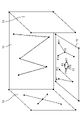
- FIG. 8 is a schematic diagram showing environmental information of the robot according to the first embodiment.
- the circle and cross symbol is a three-dimensional point cloud of environmental information.
- the environment information is expressed by drawing feature points on the environment shown in FIG.
- the feature point P1 of the three-dimensional point cloud shown in the environmental information of FIG. 8 is calculated based on the feature point P1 of the environmental image information E1 of FIG. 7 and the feature point P1 of the environmental image information E2.
- the feature point P3 of the three-dimensional point cloud shown in the environmental information of FIG. 8 is calculated based on the feature point P3 of the environmental image information E2 of FIG. 7 and the feature point P3 of the environmental image information E3. be.
- it is converted into the environmental information represented by the feature points of the three-dimensional point cloud.
- FIG. 9 is a flowchart showing a method of calculating target work information according to the first embodiment.
- the target work information is calculated after the environmental information is calculated, and the calculated environmental information and the target captured image are used.
- the target work information includes a first target work information corresponding to the first target image information and a second target work information corresponding to the second target image information.
- control unit 222 transmits the control information for acquiring the target image information to the robot 10 and operates the robot 10 (S401).
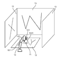
- the robot 10 is in a posture capable of accomplishing the work, that is, the target state of the robot 10.
- FIG. 10 is a schematic diagram showing a target state of the robot according to the first embodiment.
- the image information acquisition unit 221 acquires the captured image captured by the camera 103 (S402). This is called a target captured image.
- the target captured image may be an image other than the image used when calculating the target work information.
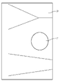
- FIG. 11 is a schematic diagram showing a target captured image in the first embodiment.
- the screw hole 11 is shown in the target captured image.
- the substrate 12 and the wall 13 may be shown in the target captured image.
- FIG. 12 is a schematic diagram showing the first target image information in the first embodiment.
- the circled cross symbol in FIG. 12 represents a feature in the two-dimensional space obtained by processing the target captured image by the first image processing.
- the feature is drawn on the target image described with reference to FIG.
- the feature points P11 to P19 are those obtained by extracting the feature points by the first image processing based on the target captured image.
- the first image processing is the image processing used when acquiring the environmental information.
- the first target work information is based on the environmental information as shown in FIG. 8 and the first target image information as shown in FIG. 12, and the feature points P1 to P9 in FIG. 8 and the feature points P9 in FIG. 12 are shown. It is calculated by associating the feature points P11 to P19 with each other. By associating in this way, the position / posture of the camera in FIG. 8 when the image of FIG. 12 is imaged can be calculated, and the position / posture of the camera obtained by the processing is the first target work information.
- SLAM is a known method for calculating the first target work information.
- the image information acquisition unit 221 calculates the second target image information based on the target captured image, and the target work information calculation unit 225 second based on the second target image information.
- the target work information of (S404) is calculated.
- FIG. 13 is a schematic diagram showing the second target image information in the first embodiment.
- the circled cross symbol in FIG. 13 indicates a feature in the two-dimensional space in which the target captured image is processed by the second image processing.
- the feature is drawn on the target image described with reference to FIG.
- the second image processing is an image processing focusing on a work object (screw hole 11).
- the second image processing in the present embodiment is to focus on the screw hole 11 and extract the feature points thereof.
- the characteristics of the screw hole 11 extracted in the second image processing are the center coordinates of the screw hole 11 and the contours of the long-axis and short-axis screw holes 11 when the screw hole 11 is recognized as an ellipse. Extract the intersection of.
- the second image processing since local information of the work object (screw hole 11) is acquired, it is desirable that the second image processing is a limited image process that acts only on the work object (screw hole 11).
- the second target image information is used as it is.
- the second target work information may be calculated separately based on the second target image information. For example, when the second target image information is a set of feature points in a two-dimensional space, it is not necessary to select the feature points to be used and not to use the other feature points.
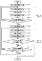
- FIG. 14 is a flowchart showing the control operation of the robot according to the first embodiment.
- the robot is controlled after the environmental information and the target work information are calculated.
- the image information acquisition unit 221 acquires the captured image, executes the first image processing on the acquired captured image, and acquires the first image information (S501).
- FIG. 15 is a schematic diagram showing a captured image of the camera 103 in the initial state of the robot 10 in the first embodiment.
- the initial state of the robot 10 is that the robot arm 101, the driver 102, and the camera 103 face the wall 13, so that the screw hole 11 is not shown in the captured image.
- the first image processing is executed, feature points can be taken from the pattern on the wall 13.
- the second image processing is executed, the feature points of the screw holes 11 cannot be extracted because the screw holes 11 do not exist in the captured image. Therefore, control cannot be performed by the conventional method using the feature points of the screw hole 11. Therefore, in the present embodiment, the control is executed by also using the characteristic points of the environment.
- step S501 in FIG. 14 control is performed by the first step (S502 to S505).
- the first control information calculation unit 226 calculates the first control information based on the environmental information, the first target work information, and the first image information (S502). The control procedure of the first work information will be described below.
- the first work information at the time of imaging in the environmental information is acquired.
- the work information is the position / posture of the camera 103.
- SLAM can be mentioned.
- the first control information is calculated.
- a visual servo can be mentioned.
- step S502 the control unit 222 controls the robot 10 using the calculated first control information (S503).
- step S503 the image information acquisition unit 221 acquires a third image information in the same manner as in step S501 (S504).
- the processor 22 determines whether or not the screw hole 11 exists in the third image information acquired in step S503 (S505).
- the second image processing is executed on the third image information, the feature points of the screw holes 11 are extracted, and if the feature points can be extracted, it is determined as "True", and in other cases, it is determined as "False”.
- the second image processing is executed on the third image information, the feature points of the screw hole 11 are extracted, and if the feature points are within a radius of 100 pixels from the center of the captured image, it is set to "True”. In other cases, it is judged as "False”. For example, YOLO (You Only Look None) is used for the captured image, and if the captured image has a screw hole 11, it is determined to be "True”, and if not, it is determined to be "False”.
- step S505 is not limited to the above. For example, it may be determined whether or not the work goal is achieved. For example, if the third work information is acquired based on the environment information and the third image information, and the third work information converges on the first target work information, it is set to "True", otherwise. Judged as "False”. Specifically, when the third work information (position / posture of the camera in the present embodiment) and the first target work information (position / posture of the target camera in the present embodiment) are compared. If the camera position error is within 5 [mm] and the camera posture error is within 0.1 [rad], it is judged as "True”, and in other cases, it is judged as "False”.
- step S505 False
- the third image information is replaced with the first image information, and the processing of the first step (S502 to S505) is executed. do. Since the target work information includes the information of the screw hole 11, the screw hole 11 is included in the third image information by repeatedly executing the first step (S502 to S505).
- the image information acquisition unit 221 acquires the image information, executes the second image processing on the acquired image, and performs the second image processing.
- the image information of 2 is calculated (S506).
- the second image information may be calculated by using the captured image used for calculating the third image information in step S504.
- the second image information may be calculated using the information at that time.
- step S506 control is performed by the second step (S507 to S511).
- the second control information calculation unit 227 calculates the second control information based on the second target work information and the second image information (S507).
- the second work information control procedure will be described below.
- the difference between the second target work information (in the case of the present embodiment, the feature of the ellipse of the target screw hole 11) and the current work information (in the case of the present embodiment, the feature of the ellipse of the screw hole 11) is 0.
- the second control information is calculated.
- a known method for calculating the second control information includes a visual servo.
- step S507 the control unit 222 controls the robot 10 using the calculated second control information (S508).
- step S508 the image information acquisition unit 221 acquires the fourth image information (S509) in the same manner as in step S506.
- the processor 22 determines whether or not the fourth image information acquired in step S509 achieves the target work information (S510).
- the fourth image information achieves the target work information, for example, when the error between the feature in the second target work information and the feature in the fourth image information is equal to or less than a certain value.
- step S509 If the fourth image information has achieved the second target work information in step S509 (S510: True), the control is terminated. For example, when comparing each element of the fourth image information and the second target work information, if the error of each element is less than 1 pixel, it is determined as "True”, and in other cases, it is determined as "False”. May be good.
- step S511 If the fourth image information does not achieve the second target work information in step S509 (S510: False), it is determined whether or not the screw hole 11 exists within a specific range of the fourth image information. (S511). The determination in step S511 may be performed in the same manner as in step S505.
- step S511 When it is determined in step S511 that the screw hole 11 exists within a specific range of the fourth image information (S511: True), the fourth image information is replaced with the second image information, and the second step (S507). ⁇ S511) is executed. By repeating the second step (S507 to S511), the feature of the fourth image information converges on the target work information.
- step S511 When it is determined in step S511 that the screw hole 11 does not exist within a specific range of the fourth image information (S511: False), the second step cannot be performed again. Therefore, in order to capture the screw hole 11 again, the process returns to the first step (S502 to S505).
- the environment information and the target image information are calculated in advance, the first control information is calculated based on the environment information, the control by the first control information is executed, and then the environment.
- the second control information is calculated based on the information, and the control by the second control information is executed.
- FIG. 16 is a sequence diagram showing a control operation that realizes the work of the robot 10 in the second embodiment. Steps S201 to S204, S207 to S209, and S212 refer to FIG.
- control device 2 calculates a third control information based on the first control information and the second control information (S601).
- control device 2 transmits the third control information to the robot 10 (S602).
- the robot 10 operates based on the received control information (S603).
- FIG. 17 is a block diagram showing a hardware configuration of the control system 1A of the robot 10 according to the second embodiment.
- the control system 1A, the control device 2A, and the processor 22A differ from the first embodiment in that they have a third control information calculation unit 228.
- the same components as those in the first embodiment are designated by the same reference numerals, and the description thereof will be omitted.
- the third control information calculation unit 228 is based on the first control information calculated from the first control information calculation unit 226 and the second control information calculated from the second control information calculation unit 227.
- the control information of 3 is calculated, and the third control information is transmitted to the control unit 222.
- the control system 1A of the second embodiment has no difference between the flowchart diagram for calculating the environmental information and the flowchart diagram for calculating the target work information with the control system 1 of the first embodiment, so only the control operation of the robot is performed. explain.
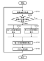
- FIG. 18 is a flowchart showing the control operation of the robot according to the second embodiment.
- the robot is controlled after the environmental information and the target work information are calculated.
- the processor 22A acquires an captured image from the image information acquisition unit 221 and calculates the first image information in the first image processing and the second image information in the second image processing (S701). ..
- both the first image information and the second image information are always calculated from the captured image.
- step S701 the processor 22A determines whether or not the captured image has achieved the work goal (S702).
- Step S702 may be determined in the same manner as in step S510 of the first embodiment.
- step S702 If the captured image has achieved the work target in step S702 (S702: True), the control is terminated.
- step S702 False
- the processor 22A simultaneously performs the processing of the first step (S703) and the processing of the second step (S704), and the first step is performed.
- the process of the third step (S705 and S706) is not executed until the process of the step (S703) and the process of the first step (S703) are completed.
- Step S702 the processor 22A calculates the first control information based on the environment information, the first target work information, and the first image information (S703).
- Step S703 may be calculated in the same manner as in step S502 of the first embodiment.
- Step S702 the processor 22A calculates the second control information based on the second target work information and the second image information (S704).
- Step S704 may be calculated in the same manner as in step S507 of the first embodiment.
- the processor 22A calculates the third control information based on the first control information and the second control information (S705).
- the third control information may be obtained by a weighted sum of the first control information and the second control information.
- the first control information may be used as it is when the second control information is not required.
- the smaller the error between the second target work information and the second image information the larger the weight of the second control information may be.
- the first control information and the second control information it is possible to control when the work object does not exist in the image captured by the camera, which is an advantage of the first control information. And, it is possible to perform control by combining the points that can be controlled with high accuracy, which is an advantage of the second control information.
- the above contents are realized by the two-step control, whereas in the second embodiment, the control having no hierarchical structure is possible.
- step S705 the control unit 222 controls the robot 10 using the calculated second control information (S706). After step S706, the process returns to step S701.
- the environmental information and the target image information are calculated in advance, the first control information calculated based on the environmental information, and the second control calculated based on the environmental information.
- the third control information is calculated, and the control by the third control information is executed.
- the first embodiment and the second embodiment have been described as examples of the techniques disclosed in the present application.
- the technique in the present disclosure is not limited to this, and can be applied to embodiments in which changes, replacements, additions, omissions, etc. have been made. It is also possible to combine the components described in the first and second embodiments to form a new embodiment.
- the feature of the captured image is a set of coordinate points in the two-dimensional image.
- its feature is a set of coordinate pairs of the start point and the end point of the two-dimensional image.
- its feature is a set of pairs of the center coordinates of the ellipse in the two-dimensional image and the vectors of the major axis and the minor axis.
- its feature is a set of pairs of coordinates of a point in a two-dimensional image and two vectors.
- a plane figure or a three-dimensional figure can be finally displayed as a set of parameters of points or lines. It can also be indicated by parameters such as image color and image brightness. Therefore, the characteristics of the captured image can be indicated by a set of parameters indicating the characteristics of the two-dimensional image.
- the feature of the environmental information is a set of coordinate points in the three-dimensional space.
- the environmental information can be indicated by a set of pairs of a start point and an end point in a three-dimensional space.
- the environmental information can be indicated by the center coordinates of the ellipse in three-dimensional space and a set of vector pairs of a major axis and a minor axis.
- the environment information can be indicated by a set of pairs of coordinates of a certain point in a three-dimensional space and two vectors.
- the environmental information can be indicated by a set of pairs of coordinates of a certain point in a three-dimensional space and three vectors. Moreover, you may use these examples in combination. In this way, a plane figure or a three-dimensional figure can be finally displayed as a set of parameters of points or lines.
- the color of the image, the brightness of the image, and the like can be indicated by parameters projected onto the three-dimensional space. Therefore, the environmental information can be shown by a set of parameters showing the characteristics in the three-dimensional space.
- the first target work information and the first work information are the positions and postures of the cameras.
- the first target work information and the first work information may be calculated from the environmental information and the first target image information or the first image information.
- it is the relative position of the work object when viewed from the position of the camera.
- it is a feature including the outside of the imaging range when viewed from the position of the camera.
- the second target work information and the second work information are a set of coordinate points in the captured image.
- the second target work information and the second work information may be calculated from the second target image information or the second image information.
- the position / posture of the work object in the image For example, it is a combination of the feature and the position / posture of the work object in the image.
- the environmental information was calculated before the control.
- the environment may fluctuate during control, causing a difference between the actual environment and the calculated environmental information. Therefore, the environmental information may be adapted to the actual environment by updating the environmental information using the captured image.
- the target work information was calculated before the control. However, it is conceivable to perform other work during control or to adjust the target work information to changes in the environment. Therefore, it may be dynamically changed to the target work information according to the work to be performed or the actual environment.
- a camera was used as a sensor.
- a sensor other than the camera may be used as long as the information on the environment can be acquired.
- a depth sensor is used as a sensor.
- the first image processing a portion having a large change in depth is extracted. This makes it possible to calculate the characteristics of the environment corresponding to the pattern of the environment as in the first embodiment.
- the second image processing a portion having an elliptical depth shape is extracted. Thereby, the feature of the work object corresponding to the hole of the screw hole 11 as in the first embodiment is extracted.
- the environmental information expresses the features of the depth information extracted by the first image processing as a three-dimensional point cloud.
- the depth information acquired in the target state of the robot is used, and the information extracted by the first image processing and the second image processing is used.
- the depth information and using it as a feature control is possible in the same manner as the contents described in the first and second embodiments.
- the first embodiment is a robot control method in a control device connected to a robot that performs work on a work object and a sensor mounted on the robot, and the environment around the robot is set to a plurality of positions. Based on multiple environmental image information acquired from angles, environmental information indicating the environment around the robot is calculated, the first image information is acquired by the camera, and target work information indicating the work target for the robot's work object. The first step of calculating the first control information so that the robot approaches the work target based on the environment information and the first image information, and transmitting the first control information to the robot, and the first step.
- the second image information is acquired by the camera, and based on the target work information and the second image information, the second control information that causes the robot to approach the work target is calculated, and the robot The control is executed based on the second step of transmitting the second control information to the robot.
- control can be performed by using the environmental information even when the work object is not captured in the captured image.
- the second step enables highly accurate control based on the captured image.
- the image information is acquired by the camera, and when it is determined that the work object does not exist in the image information based on the image information, the first step is executed.
- control is executed so that the first work information approaches the first target work information.
- the first target work information includes information about the work object. Therefore, since the control is executed from the time when the information of the work object does not exist in the image information until the information of the work object exists, the second step can be executed.
- the image information is acquired by the camera, and when it is determined that the robot does not meet the work target based on the environment information and the image information, the first step is executed.
- the work target can be controlled to be achieved by controlling the work target so as to approach the work target again.
- the image information is acquired by the camera, and when it is determined that the robot does not meet the work target based on the image information, the second step is executed.
- the work target can be controlled so as to approach the work target again, so that the work target can be achieved.
- the image information is acquired by the camera, and when the work object does not exist within a certain range of the current image information, the first step is executed. As a result, even if the work object is lost during the second step, it is possible to control the work object to be recaptured by returning to the first step.
- the target work information includes the characteristic information of the work object at the time of finishing the work, and the environmental information corresponds to the characteristic information including the work object and the workbench, and the work object and the workbench existing in the environment.
- the first image information includes the feature information of at least one of the work object and the workbench at the time of acquisition, including the three-dimensional position information corresponding to the feature information of.
- the three-dimensional position information has an expression peculiar to an object, which is composed of a parameter indicating a point, a line, a plane figure, or a parameter indicating a three-dimensional figure.
- the target work information includes the feature information of the work object when the work is executed, and the second image information includes the feature information of the work object at the time of acquisition.
- the target work information includes the feature information of the work object when the work is executed.
- the feature information has an expression peculiar to an object, which is composed of a parameter indicating a point, a line, a plane figure, or a parameter indicating a three-dimensional figure.
- the environmental information is updated using the first image information and the second image information. As a result, even when the environment changes, it is possible to perform control adapted to the environment by updating the environment information.
- the environmental image information is an image captured by the camera.
- the second embodiment is a robot control method in a control device connected to a robot that performs work on a work object and a sensor mounted on the robot, and the environment around the robot is set to a plurality of positions. Based on a plurality of environmental image information taken from an angle, environmental information indicating the environment around the robot is calculated, the first image information and the second image information are acquired using a camera, and the robot's work target. The first step of calculating the first control information that causes the robot to approach the work target based on the target work information indicating the work target for the object, the environment information, and the first image information, and the target work information.
- the control is executed based on the third step of calculating the control information of 3 and transmitting the third control information to the robot.
- control information that can be controlled even when the work object is not captured in the first step is calculated, highly accurate control information for the work object is calculated in the second step, and the work object is calculated in the third step.
- the robot After executing the third step, if it is determined that the robot does not meet the work goal, the robot performs the above work based on the target work information, the environment information, and the third image information acquired by using the camera.
- the fourth control information that approaches the target is calculated
- the fifth control information that approaches the work target is calculated based on the target work information and the fourth image information acquired by using the camera.
- the sixth control information is calculated based on the fourth control information and the fifth control information, and the sixth control information is transmitted to the robot.
- This disclosure is applicable to a control device that adapts to various environments and performs work by a robot. Specifically, this disclosure can be applied to factory assembly work, warehouse arrangement work, backyard delivery / delivery work, and the like.
Landscapes
- Engineering & Computer Science (AREA)
- Robotics (AREA)
- Mechanical Engineering (AREA)
- Manipulator (AREA)
Priority Applications (4)
| Application Number | Priority Date | Filing Date | Title |
|---|---|---|---|
| EP21886014.6A EP4238720A4 (en) | 2020-10-30 | 2021-10-20 | ROBOT CONTROL METHODS |
| JP2022559051A JP7482359B2 (ja) | 2020-10-30 | 2021-10-20 | ロボット制御方法 |
| CN202180072683.XA CN116348257A (zh) | 2020-10-30 | 2021-10-20 | 机器人控制方法 |
| US18/138,913 US12515344B2 (en) | 2020-10-30 | 2023-04-25 | Robot control method |
Applications Claiming Priority (2)
| Application Number | Priority Date | Filing Date | Title |
|---|---|---|---|
| JP2020-182018 | 2020-10-30 | ||
| JP2020182018 | 2020-10-30 |
Related Child Applications (1)
| Application Number | Title | Priority Date | Filing Date |
|---|---|---|---|
| US18/138,913 Continuation US12515344B2 (en) | 2020-10-30 | 2023-04-25 | Robot control method |
Publications (1)
| Publication Number | Publication Date |
|---|---|
| WO2022091895A1 true WO2022091895A1 (ja) | 2022-05-05 |
Family
ID=81382337
Family Applications (1)
| Application Number | Title | Priority Date | Filing Date |
|---|---|---|---|
| PCT/JP2021/038697 Ceased WO2022091895A1 (ja) | 2020-10-30 | 2021-10-20 | ロボット制御方法 |
Country Status (6)
| Country | Link |
|---|---|
| US (1) | US12515344B2 (https=) |
| EP (1) | EP4238720A4 (https=) |
| JP (1) | JP7482359B2 (https=) |
| CN (1) | CN116348257A (https=) |
| TW (1) | TW202231427A (https=) |
| WO (1) | WO2022091895A1 (https=) |
Families Citing this family (2)
| Publication number | Priority date | Publication date | Assignee | Title |
|---|---|---|---|---|
| US20250285320A1 (en) * | 2021-03-10 | 2025-09-11 | Kawasaki Jukogyo Kabushiki Kaisha | Own position estimating system and own position estimating method |
| JP7590577B2 (ja) * | 2021-07-12 | 2024-11-26 | 株式会社安川電機 | ロボット制御システム、ロボットシステム、ロボット制御方法、およびロボット制御プログラム |
Citations (7)
| Publication number | Priority date | Publication date | Assignee | Title |
|---|---|---|---|---|
| JPH06262568A (ja) * | 1993-03-08 | 1994-09-20 | Nippondenso Co Ltd | 視覚に基く三次元位置および姿勢の認識方法とその装置 |
| JP2003015739A (ja) * | 2001-07-02 | 2003-01-17 | Yaskawa Electric Corp | 外環境地図、並びに自己位置同定装置および誘導制御装置 |
| JP2003305675A (ja) | 2002-04-15 | 2003-10-28 | Denso Wave Inc | 視覚認識装置 |
| JP2008006519A (ja) * | 2006-06-27 | 2008-01-17 | Toyota Motor Corp | ロボット装置及びロボット装置の制御方法 |
| JP2015003348A (ja) * | 2013-06-19 | 2015-01-08 | セイコーエプソン株式会社 | ロボット制御システム、制御装置、ロボット、ロボット制御システムの制御方法及びロボットの制御方法 |
| JP2019077026A (ja) * | 2017-10-19 | 2019-05-23 | キヤノン株式会社 | 制御装置、ロボットシステム、制御装置の動作方法及びプログラム |
| JP2020146773A (ja) * | 2019-03-12 | 2020-09-17 | 株式会社不二越 | ハンドリング装置およびロボット装置 |
Family Cites Families (8)
| Publication number | Priority date | Publication date | Assignee | Title |
|---|---|---|---|---|
| JP2011212764A (ja) * | 2010-03-31 | 2011-10-27 | Toyota Motor Corp | ロボットの遠隔操作システム |
| JP6000579B2 (ja) * | 2012-03-09 | 2016-09-28 | キヤノン株式会社 | 情報処理装置、情報処理方法 |
| JP6108860B2 (ja) * | 2013-02-14 | 2017-04-05 | キヤノン株式会社 | ロボットシステム及びロボットシステムの制御方法 |
| JP5954274B2 (ja) * | 2013-07-26 | 2016-07-20 | 株式会社安川電機 | ロボットシステム |
| CN106426186B (zh) * | 2016-12-14 | 2019-02-12 | 国网江苏省电力公司常州供电公司 | 一种基于多传感器信息融合的带电作业机器人自主作业方法 |
| JP7145851B2 (ja) * | 2017-06-13 | 2022-10-03 | 川崎重工業株式会社 | 作業システム |
| US11358290B2 (en) | 2017-10-19 | 2022-06-14 | Canon Kabushiki Kaisha | Control apparatus, robot system, method for operating control apparatus, and storage medium |
| EP4221944A1 (en) * | 2020-11-10 | 2023-08-09 | Bright Machines, Inc. | Method and system for improved auto-calibration of a robotic cell |
-
2021
- 2021-10-20 JP JP2022559051A patent/JP7482359B2/ja active Active
- 2021-10-20 CN CN202180072683.XA patent/CN116348257A/zh active Pending
- 2021-10-20 EP EP21886014.6A patent/EP4238720A4/en not_active Withdrawn
- 2021-10-20 WO PCT/JP2021/038697 patent/WO2022091895A1/ja not_active Ceased
- 2021-10-21 TW TW110139081A patent/TW202231427A/zh unknown
-
2023
- 2023-04-25 US US18/138,913 patent/US12515344B2/en active Active
Patent Citations (7)
| Publication number | Priority date | Publication date | Assignee | Title |
|---|---|---|---|---|
| JPH06262568A (ja) * | 1993-03-08 | 1994-09-20 | Nippondenso Co Ltd | 視覚に基く三次元位置および姿勢の認識方法とその装置 |
| JP2003015739A (ja) * | 2001-07-02 | 2003-01-17 | Yaskawa Electric Corp | 外環境地図、並びに自己位置同定装置および誘導制御装置 |
| JP2003305675A (ja) | 2002-04-15 | 2003-10-28 | Denso Wave Inc | 視覚認識装置 |
| JP2008006519A (ja) * | 2006-06-27 | 2008-01-17 | Toyota Motor Corp | ロボット装置及びロボット装置の制御方法 |
| JP2015003348A (ja) * | 2013-06-19 | 2015-01-08 | セイコーエプソン株式会社 | ロボット制御システム、制御装置、ロボット、ロボット制御システムの制御方法及びロボットの制御方法 |
| JP2019077026A (ja) * | 2017-10-19 | 2019-05-23 | キヤノン株式会社 | 制御装置、ロボットシステム、制御装置の動作方法及びプログラム |
| JP2020146773A (ja) * | 2019-03-12 | 2020-09-17 | 株式会社不二越 | ハンドリング装置およびロボット装置 |
Non-Patent Citations (1)
| Title |
|---|
| See also references of EP4238720A4 |
Also Published As
| Publication number | Publication date |
|---|---|
| EP4238720A1 (en) | 2023-09-06 |
| TW202231427A (zh) | 2022-08-16 |
| US20230256614A1 (en) | 2023-08-17 |
| JP7482359B2 (ja) | 2024-05-14 |
| EP4238720A4 (en) | 2024-04-10 |
| CN116348257A (zh) | 2023-06-27 |
| US12515344B2 (en) | 2026-01-06 |
| JPWO2022091895A1 (https=) | 2022-05-05 |
Similar Documents
| Publication | Publication Date | Title |
|---|---|---|
| CN114494426B (zh) | 用于控制机器人来在不同的方位拿起对象的装置和方法 | |
| JP5850962B2 (ja) | ビジュアルフィードバックを利用したロボットシステム | |
| US11911914B2 (en) | System and method for automatic hand-eye calibration of vision system for robot motion | |
| US9844882B2 (en) | Conveyor robot system provided with three-dimensional sensor | |
| JP6815309B2 (ja) | 作動システムおよびプログラム | |
| CN115519536A (zh) | 用于3d眼手协调的误差校正和补偿的系统和方法 | |
| JP2019155556A (ja) | ロボットの制御装置、ロボット、ロボットシステム、並びに、カメラの校正方法 | |
| CN109909999B (zh) | 一种获取机器人tcp坐标的方法和装置 | |
| US12515344B2 (en) | Robot control method | |
| US20230115521A1 (en) | Device and method for training a machine learning model for recognizing an object topology of an object from an image of the object | |
| US11986960B2 (en) | Apparatus and method for training a machine learning model to recognize an object topology of an object from an image of the object | |
| CN118493383A (zh) | 一种基于云台手眼相机的机械臂位置视觉伺服方法及系统 | |
| CN120422256A (zh) | 复合机器人的机械臂控制方法、装置、设备及存储介质 | |
| JP2024001876A (ja) | 物体を操作するロボット、特に物体を受容するロボットを制御するための方法 | |
| JP2022142773A (ja) | オブジェクトのカメラ画像からオブジェクトの場所を位置特定するための装置及び方法 | |
| CN115205371A (zh) | 用于根据对象的摄像机图像定位对象的部位的设备和方法 | |
| CN119784839A (zh) | 机械臂位姿确定方法、设备、存储介质及程序产品 | |
| CN114407011A (zh) | 异形工件抓取规划方法、规划装置及异形工件抓取方法 | |
| CN115338874B (zh) | 基于激光雷达的机器人实时控制方法 | |
| JP7583942B2 (ja) | ロボット制御装置、ロボット制御システム、及びロボット制御方法 | |
| CN116690568A (zh) | 基于机器视觉的机械臂控制方法、装置、设备及存储介质 | |
| Qu et al. | Multi-cameras visual servoing for dual-arm coordinated manipulation | |
| CN115026808A (zh) | 手眼标定方法、手眼标定系统、计算机设备及存储装置 | |
| US20240331213A1 (en) | Method for ascertaining a descriptor image for an image of an object | |
| KR20250165016A (ko) | 촉각 센서를 이용한 로봇의 제어방법 및 이의 제어시스템 |
Legal Events
| Date | Code | Title | Description |
|---|---|---|---|
| 121 | Ep: the epo has been informed by wipo that ep was designated in this application |
Ref document number: 21886014 Country of ref document: EP Kind code of ref document: A1 |
|
| ENP | Entry into the national phase |
Ref document number: 2022559051 Country of ref document: JP Kind code of ref document: A |
|
| NENP | Non-entry into the national phase |
Ref country code: DE |
|
| ENP | Entry into the national phase |
Ref document number: 2021886014 Country of ref document: EP Effective date: 20230530 |