WO2022091817A1 - Rail transportation system, method for controlling rail transportation system, and trackside facility shape measurement system - Google Patents
Rail transportation system, method for controlling rail transportation system, and trackside facility shape measurement system Download PDFInfo
- Publication number
- WO2022091817A1 WO2022091817A1 PCT/JP2021/038244 JP2021038244W WO2022091817A1 WO 2022091817 A1 WO2022091817 A1 WO 2022091817A1 JP 2021038244 W JP2021038244 W JP 2021038244W WO 2022091817 A1 WO2022091817 A1 WO 2022091817A1
- Authority
- WO
- WIPO (PCT)
- Prior art keywords
- railway line
- equipment
- along
- train
- observation data
- Prior art date
Links
- 238000005259 measurement Methods 0.000 title claims abstract description 140
- 238000000034 method Methods 0.000 title claims abstract description 44
- 230000015572 biosynthetic process Effects 0.000 claims description 11
- 230000005856 abnormality Effects 0.000 abstract description 5
- 238000001514 detection method Methods 0.000 description 125
- 238000012545 processing Methods 0.000 description 42
- 238000012544 monitoring process Methods 0.000 description 30
- 230000032258 transport Effects 0.000 description 28
- 238000010586 diagram Methods 0.000 description 21
- 230000008569 process Effects 0.000 description 16
- 238000006243 chemical reaction Methods 0.000 description 4
- 238000012423 maintenance Methods 0.000 description 3
- 230000002596 correlated effect Effects 0.000 description 2
- 230000000875 corresponding effect Effects 0.000 description 2
- 230000000694 effects Effects 0.000 description 2
- 238000009434 installation Methods 0.000 description 2
- 230000008859 change Effects 0.000 description 1
- 238000012790 confirmation Methods 0.000 description 1
- 238000013461 design Methods 0.000 description 1
- 238000005516 engineering process Methods 0.000 description 1
- 238000012986 modification Methods 0.000 description 1
- 230000004048 modification Effects 0.000 description 1
- 230000003287 optical effect Effects 0.000 description 1
- 230000009467 reduction Effects 0.000 description 1
Images


Classifications
-
- B—PERFORMING OPERATIONS; TRANSPORTING
- B61—RAILWAYS
- B61L—GUIDING RAILWAY TRAFFIC; ENSURING THE SAFETY OF RAILWAY TRAFFIC
- B61L23/00—Control, warning, or like safety means along the route or between vehicles or vehicle trains
- B61L23/04—Control, warning, or like safety means along the route or between vehicles or vehicle trains for monitoring the mechanical state of the route
- B61L23/041—Obstacle detection
-
- B—PERFORMING OPERATIONS; TRANSPORTING
- B61—RAILWAYS
- B61L—GUIDING RAILWAY TRAFFIC; ENSURING THE SAFETY OF RAILWAY TRAFFIC
- B61L25/00—Recording or indicating positions or identities of vehicles or vehicle trains or setting of track apparatus
- B61L25/02—Indicating or recording positions or identities of vehicles or vehicle trains
- B61L25/025—Absolute localisation, e.g. providing geodetic coordinates
-
- B—PERFORMING OPERATIONS; TRANSPORTING
- B61—RAILWAYS
- B61L—GUIDING RAILWAY TRAFFIC; ENSURING THE SAFETY OF RAILWAY TRAFFIC
- B61L25/00—Recording or indicating positions or identities of vehicles or vehicle trains or setting of track apparatus
- B61L25/06—Indicating or recording the setting of track apparatus, e.g. of points, of signals
-
- B—PERFORMING OPERATIONS; TRANSPORTING
- B61—RAILWAYS
- B61L—GUIDING RAILWAY TRAFFIC; ENSURING THE SAFETY OF RAILWAY TRAFFIC
- B61L15/00—Indicators provided on the vehicle or vehicle train for signalling purposes ; On-board control or communication systems
- B61L15/0072—On-board train data handling
Definitions
- the present invention relates to an orbital transportation system, a control method for the orbital transportation system, and an equipment shape measurement system along the railway line.
- Patent Document 2 as a method of performing three-dimensional measurement with a camera, a method of photographing an object from a plurality of places and obtaining the three-dimensional coordinates and a shape of the object by triangular survey, or a method of preparing a plurality of cameras and taking an image.
- a method of using a stereo camera system, a method of obtaining a three-dimensional shape of a subject based on SfM (Structure from Motion) technology from multiple captured images taken while the vehicle is moving by a camera mounted on the vehicle, etc. Is described.
- FIG. 1 is a schematic diagram showing an example of measurement by a sensor installed on the front surface of the leading vehicle
- FIG. 2 is a schematic diagram showing an example of measurement by a sensor installed on the upper part of the leading vehicle.
- FIG. 2 there is a method of expanding the measurement area of the object by installing the sensor group of the ambient environment observation unit 107 on the upper part of the vehicle, but the sensor group will be installed at a high place. , There are problems such as difficult maintenance of the sensor group.
- the present invention has been made in consideration of this point, and an object of the present invention is to provide a track transportation system, a control method of a track transportation system, and a line equipment shape measurement system that can confirm abnormalities of railway railway line equipment from multiple viewpoints.
- one of the typical track transportation systems of the present invention is installed on a train, observes the surrounding environment while the train is running, including known facilities along the railway line, and acquires ambient environment observation data.
- the ambient environment observation unit and the railway equipment shape measurement system that obtains the three-dimensional shape of the railway equipment by superimposing multiple ambient environment observation data including the railway equipment acquired at multiple positions on the track based on the track of the rail. To prepare for.
- FIG. 3 is a diagram showing an example of the configuration of the orbital transportation system.
- a track transportation system 100 including a transportation vehicle 102, a self-position estimation system 101, an ambient environment observation unit 107, an obstacle detection system 103, and a railway line equipment shape measurement system 104 will be described.
- the transportation vehicle 102 is a vehicle that transports passengers and freight traveling along the track.
- the ambient environment observation unit 107 is a device installed in front of and behind the transportation vehicle 102 to acquire the position, shape, color, reflection intensity, etc. of an object around the transportation vehicle 102, and is a camera, a laser radar, or a device. Alternatively, it is composed of millimeter-wave radar and the like.
- the obstacle detection system 103 is a system that detects obstacles based on the position / attitude information 133 of the transportation vehicle 102 acquired from the self-position estimation system 101.
- the obstacle detection system 103 When the obstacle detection system 103 detects an obstacle that hinders the traveling of the transportation vehicle 102, the obstacle detection system 103 sends information regarding the existence of the obstacle to the transportation vehicle 102, and the transportation vehicle 102 Make an emergency stop.
- the obstacle detection system 103 includes a detection range setting database 123, a monitoring area setting processing unit 111, a detection target information database 112, a side boundary monitoring unit 114, a front boundary monitoring unit 113, and an obstacle detection unit 115.
- the monitoring area setting processing unit 111 acquires the obstacle detection range 138 corresponding to the position / attitude information 133 of the transportation vehicle estimated by the self-position estimation system 101 from the detection range setting database 123, and detects the obstacle. Set the monitoring area.
- the detection range setting database 123 for example, it is conceivable to register the area within the building limit as the detection range, and register the area near the home or the area where maintenance work is performed as an area that is not exceptionally detected.
- the side boundary monitoring unit 114 and the front boundary monitoring unit 113 use a camera, a laser radar, a millimeter wave radar, or the like to set the boundary detection areas 139 and 140 at the side boundary and the front boundary of the obstacle monitoring area. It has a function to detect objects.
- the side boundary monitoring unit 114 and the front boundary monitoring unit 113 may use the sensor of the ambient environment observation unit 107 as the obstacle detection sensor.
- the detection target information database 112 can record the position of an existing object (rail, sign, etc.) having a detection rate equal to or higher than a certain value in advance and its reflectance.
- the obstacle detection unit 115 can detect obstacles in the obstacle monitoring area based on the monitoring results 144 and 143 by the side boundary monitoring unit 114 and the front boundary monitoring unit 113.
- the obstacle detection unit 115 When the obstacle detection unit 115 detects an obstacle that interferes with the operation of the transportation vehicle 102, the obstacle detection unit 115 transmits the information of "obstacle: present" to the transportation vehicle control drive unit 106 of the transportation vehicle 102.
- FIG. 4 is a diagram showing an example of the configuration of the self-position estimation system 101 and the railway line equipment shape measurement system 104.
- the self-position estimation system 101 includes an observation data selection processing unit 116, a vehicle attitude estimation processing unit 117, an ambient environment data coordinate conversion processing unit 118, an ambient environment map generation processing unit 119, an ambient environment map database 120, and a scan matching self-position estimation process. It is composed of a unit 121.
- the self-position estimation system 101 is for transportation in the external coordinate system based on the ambient environment observation data 130 acquired by the ambient environment observation unit 107, the ambient environment map database 120 defined in the external coordinate system, and the three-dimensional rail track database 108. This is a system that estimates the position and posture of the vehicle 102 by scan matching.
- the observation data selection processing unit 116 can select the rail observation data 147 from the ambient environment observation data 130 observed by the ambient environment observation unit 107.
- the vehicle attitude estimation processing unit 117 can estimate the attitude of the transportation vehicle 102 from the rail observation data 147 and the rail position information 137 acquired from the three-dimensional rail track database 108.
- the surrounding environment data coordinate conversion processing unit 118 uses the vehicle posture 150 to obtain the surrounding environment observation data 130 from the vehicle coordinate system fixed to the transport vehicle 102, and the surrounding environment map database 120 and the three-dimensional rail track database 108 are used. It can be converted into the defined external coordinate system to obtain the ambient environment measurement data 151 (hereinafter, the ambient environment observation data converted into the external coordinate system may be referred to as "ambient environment measurement data”. ).
- the scan matching self-position estimation processing unit 121 uses the rail position information 137 to move on the track recorded in the three-dimensional rail track database 108 while maintaining the vehicle attitude 149, while moving the surrounding environment measurement data 151 and the surroundings.
- the self-position of the vehicle can be estimated by matching with the surrounding environment map data 153 recorded in the environment map database 120.
- the railway line equipment information 136 recorded in the railway line equipment database 110 may be used.
- the surrounding environment map generation processing unit 119 can generate the surrounding environment map data 153 from the surrounding environment measurement data 152.
- the railway line equipment shape measurement system 104 is composed of a three-dimensional rail track database 108, a railway line equipment shape measurement processing unit 109, and a railway line equipment database 110.
- the railway line equipment shape measurement system 104 uses the railway line equipment shape measurement processing unit 109 to measure the three-dimensional shape of the railway line equipment based on the point cloud data of the railway line equipment converted into the external coordinate system from the scan matching self-position estimation processing unit 121. Measure and record in the equipment database 110 along the railway line.
- Rail measurement data 132 can be recorded in the 3D rail track database 108.
- the railway line equipment shape measurement processing unit 109 detects the railway line equipment in the ambient environment measurement data 131 from the ambient environment measurement data 131, the rail shape model 134, and the railway line equipment information 135, and creates a three-dimensional shape model of the railway line equipment. Can be created.
- the railway line equipment database 110 it is possible to record the surrounding environment measurement data 131 in which the railway line equipment is detected and the three-dimensional shape model of the railway line equipment.
- the transportation vehicle 102 is composed of a transportation vehicle operation control unit 105 and a transportation vehicle control drive unit 106.
- the transportation vehicle operation control unit 105 is a device that generates a control drive command for the transportation vehicle 102, and an ATO device (automatic train operation device) can be mentioned as an example.
- the generated transport vehicle control drive command 146 is transmitted to the transport vehicle control drive unit 106.
- the transport vehicle operation control unit 105 can generate a control drive command so that the transport vehicle 102 travels along a target travel pattern defined by a position and a speed. Although not shown in FIG. 3, it has an internal function of detecting the position and speed of the transport vehicle 102 in order to travel along the target travel pattern.
- the pattern based on the speed limit of the transport vehicle 102 and the speed limit of the traveling section, which are known in advance, is the basis. Then, the allowable maximum speed of the transportation vehicle 102 is calculated from the position of the transportation vehicle 102 and the maximum deceleration of the transportation vehicle 102, and is reflected in the target traveling pattern of the transportation vehicle 102.
- the transportation vehicle control drive unit 106 controls and drives the transportation vehicle 102 based on the transportation vehicle control drive command 146 acquired from the transportation vehicle operation control unit 105.
- Examples of the specific device of the transport vehicle control drive unit 106 include an inverter, a motor, a friction brake, and the like.
- obstacle detection information 145 is input from the obstacle detection unit 115 to the transportation vehicle control drive unit 106.
- the transportation vehicle 102 is stopped at the station and the content of the obstacle detection information 145 is "obstacle: yes"
- the vehicle is put into a braking state and cannot start.
- the transportation vehicle 102 is traveling between stations and the content of the obstacle detection information 145 is "obstacle: present”
- braking is performed at the maximum deceleration to stop the transportation vehicle 102.
- FIG. 5 is a flowchart showing an example of a processing procedure executed by the obstacle detection system 103.
- step 201 the current position / posture 133 of the transportation vehicle 102 required for acquiring the obstacle detection range 138 is acquired from the self-position estimation system 101.
- step 202 the obstacle monitoring area is set from the obstacle detection range 138 corresponding to the current position of the transportation vehicle acquired in step 201.
- the building limit as the lateral boundary of the obstacle monitoring area and set the stoptable distance of the transport vehicle as the traveling direction boundary of the obstacle monitoring area.
- step 203 sensor information regarding obstacles in the boundary detection areas 139 and 140 set at the boundary of the obstacle monitoring area is acquired from the obstacle detection sensor, and it is determined whether or not there is an obstacle in the obstacle monitoring area. .. As a result of determining whether or not an obstacle exists in step 203, if it is determined that an obstacle exists, the process proceeds to step 204. If it is determined that there is no obstacle, the process proceeds to step 205.
- the width of the lateral boundary detection area 139 is at least when the obstacle enters the boundary, considering the size and maximum moving speed of the obstacle expected to enter the area and the sensing cycle of the obstacle detection sensor.
- the width should be such that it can be detected at least once.
- this lateral boundary detection area 139 is set to several cm to several tens of cm (more specifically, 10 cm) assuming passengers waiting at the platform, and crossing a car or the like near the railroad crossing. It is desirable to change it according to the current position of the transportation vehicle 102, such as setting it widely (for example, 1 m) assuming it.
- FIG. 6 is a diagram showing an example of sensor installation.
- FIG. 1 As a sensor for detecting the presence or absence of a side obstacle in the side boundary detection area 155, considering that the shape of the side boundary detection area 155 is a rectangle having a width of several tens of centimeters and a depth of more than 100 m, FIG. It is possible to use two LIDAR detectors 201 and 202 installed at high positions on the front left and right of the transport vehicle 102 so as to be able to detect the left and right lateral boundary detection areas 155. can.
- the detection result in the side boundary detection area 155 satisfies any of the following (condition 1) to (condition 3) as compared with the side detection target information 141 registered in the detection target information database 112. When it is determined that an obstacle has invaded.
- the stopping distance of the transportation vehicle 102 increases, and the obstacle monitoring area expands. If the reflectance of the laser to be detected at a long distance is small, it may be erroneously determined that an obstacle has entered due to condition 1. Therefore, for example, it is necessary to suppress the allowable travelable speed.
- Countermeasure 1 Only the position of an existing object (rail, sign, etc.) having a detection rate of a certain value or higher in the side boundary detection area 155 is targeted for detection.
- Countermeasure 2 An object having a detection rate of a certain value or higher is installed as a detection target in the lateral boundary detection area 155. For example, an object having a high reflectance or an object that is hard to get dirty has a high detection rate.
- the position of the detection target and its reflectance are recorded in the detection target information database 112 in advance, and only when the position of the detection target is included in the lateral boundary detection area 155 at the current position of the transportation vehicle 102. ,
- the detection target is used to judge the intrusion of obstacles.
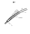
- FIG. 7 is a diagram showing an example of detection of a lateral boundary detection region when the obstacle detection system travels on a turning track.
- the detection points on the lateral boundary detection region 155 that spans a plurality of layers are used. , It is possible to determine the intrusion of obstacles even when the boundary is curved, such as a curved trajectory.
- the road surface detection points by each detection layer irradiated from the multilayer type LIDAR are shown by dotted lines, but the detection layer passing over the side boundary detection regions 155a and 155b differs depending on the distance from the vehicle and is an obstacle.
- a plurality of stereo cameras, millimeter wave radars, and laser rangefinders may be used, or these sensors may be attached to an automatic pan head to scan the side boundary detection area 155. May be good.
- a narrow-angle monocular camera including infrared rays
- a stereo camera a millimeter-wave radar
- LIDAR laser rangefinder
- the detection result (color, detection position and distance, reflection intensity of laser or millimeter wave) of any of the sensors is registered in the detection target information database 112 as the detection target information 141. , 142 may be determined that an obstacle exists in the monitoring area.
- the detection rate can be increased by using the detection results of a plurality of sensors of different types.
- the false positive rate can be reduced by using the AND of the detection result.
- the detection target registered in the detection target information database 112 may be distant and cannot be detected. Therefore, an object other than the detection target information 142 registered in the detection target information database 112 is detected. When it does, it is determined that there is an obstacle.
- step 203 If it is determined in step 203 that an obstacle exists, it is necessary to stop the transportation vehicle 102, so the obstacle detection information 145 is created in step 204. On the other hand, if it is determined that there is no obstacle, the process proceeds to step 205.
- step 205 the obstacle detection information 145 in the obstacle monitoring area is transmitted to the transportation vehicle 102.
- the above is a description of the operation of the obstacle detection system 103.
- FIG. 8 is a flowchart showing an example of a processing procedure executed by the self-position estimation system 101.
- step 401 the ambient environment observation data 130 observed by the ambient environment observation unit 107 is acquired.
- FIG. 9 is a diagram showing an example of rail detection by the self-position estimation system.
- step 402 the rail observation data 147 of FIG. 9 is selected from the ambient environment observation data 130 acquired in step 401.
- the rail observation data 147 in FIG. 9 can be selected by utilizing the shape and reflectance of the rail as well as the data detected as the rail forming one plane.
- FIG. 10 is a diagram showing an example of vehicle attitude estimation by a self-position estimation system.
- step 403 the posture of the transport vehicle 102 is estimated from the plane R formed by the rail surface obtained from the rail observation data 147 and the rail position information 137 acquired from the three-dimensional rail track database 108.
- the attitude of the transport vehicle 102 means the inclination of the transport vehicle 102 with respect to the external coordinate system ⁇ O in which the three-dimensional rail track database 108 is defined.
- the 3D rail track database 108 records 3D point cloud data passing on the left and right rails and their reflectances.
- step 404 the surrounding environment map database 120 and the three-dimensional rail track database 108 are obtained by using the vehicle posture 150 estimated in step 403 from the vehicle coordinate system ⁇ T fixed to the transport vehicle 102 for the surrounding environment observation data 130. Is converted into the defined external coordinate system ⁇ O to obtain the ambient environment measurement data 151.
- step 405 while maintaining the vehicle attitude 149 estimated in step 403 and moving on the track recorded in the three-dimensional rail track database 108, the ambient environment measurement data 151 calculated by coordinate conversion in step 404 and the surroundings The self-position of the vehicle is estimated by matching with the surrounding environment map data 153 recorded in the environment map database 120.
- FIG. 11 is a diagram showing an example of the surrounding environment in which the transportation vehicle travels
- FIG. 12 is a diagram showing an example of the surrounding environment measurement data.
- the point cloud data 151 defined by the external coordinate system ⁇ O as shown in FIG. 12 can be acquired in step 404.
- FIGS. 13 and 14 are diagrams showing an example of matching between the ambient environment measurement data and the ambient environment map data
- FIGS. 15 and 16 are diagrams showing an example of matching between the ambient environment measurement data and the ambient environment map data in an automobile. It is a figure which shows.
- the ambient environment measurement data 151 and the ambient environment map data 153 are correlated while moving in an arbitrary direction. It is necessary to obtain the position with the highest correlation value (FIG. 16) as the self-position.
- the ambient environment measurement data 151 and the ambient environment map data 153 are correlated while moving on the rail track 185 in FIG. 13, and the correlation value is the highest.
- the high position (FIG. 14) may be obtained as the self-position.
- the estimated self-position is always on the orbit, and it is possible to prevent the estimated self-position from deviating from the orbit as in the effect of multipath when GNSS is used.
- the above is a description of the operation of the self-position estimation system 101.
- FIG. 17 is a flowchart showing an example of a processing procedure executed by the equipment shape measurement system 104 along the railway line.
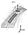
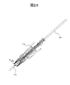
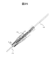
- FIGS. 18 to 21 are diagrams showing an example of ambient environment observation for acquiring ambient environment measurement data used in the railway equipment shape measurement system
- FIGS. 22 to 25 are ambient environments used in the railway equipment shape measurement system. It is a figure which shows an example of the measurement data.
- the ambient environment measurement data 131 converted into the external coordinate system is acquired from the self-position estimation system 101, and the ambient environment measurement data 131 is matched with the rail shape model 134 acquired from the three-dimensional rail track database 108.
- the relative position of the ambient environment measurement data 131 with respect to the rail track 185 is calculated.
- the relative position with respect to the rail track 185 is defined by the relative position coordinate system in which the origin 173 is taken on the rail track 185, or the distance / attitude with respect to the rail.
- the ambient environment measurement data 131 acquired at the positions of FIGS. 18 to 21 can be defined by the coordinate system ⁇ R having the origin 173 on the rail track 185 as shown in FIGS. 22 to 25.
- the railway line equipment 171 is detected from the ambient environment measurement data 131 based on the railway line equipment information (position / attitude, three-dimensional shape, color, reflectance) 135 acquired from the railway line equipment database 110.
- the position / posture of the equipment along the railway line does not necessarily have to be the position / posture in the external coordinate system, but may be the distance or the posture with respect to the rail.
- FIG. 26 is a diagram showing an example of a railway line equipment database used in the railway line equipment shape measurement system.
- step 503 the ambient environment measurement data 131 in which the alongside equipment 171 is detected is recorded in the alongside equipment database 110 for each of the detected alongside equipment 171.
- FIG. 27 is a diagram showing matching between the surrounding environment measurement data and the equipment along the railway line in the equipment shape measurement system along the railway line.
- step 504 the rail track is maintained relative to the rail estimated in step 501 with respect to the plurality of ambient environment measurement data 131 in the railway line equipment database 110 recorded for each line equipment 171.
- the ICP algorithm can be used for matching between the ambient environment measurement data 131.
- the accuracy of the three-dimensional shape model of the railway line equipment 171 is improved by giving a large weight to the measurement data 172 of the railway line equipment 171.
- the railway line equipment shape measurement system obtains the three-dimensional shape of the railway line equipment by superimposing a plurality of ambient environment measurement data including the railway line equipment acquired at a plurality of positions on the track based on the rail track. More specifically, the railway line equipment shape measurement system matches the rail measurement data included in the surrounding environment measurement data with the rail shape model, and the measurement data of the railway line equipment and the shape of the railway line equipment included in the ambient environment measurement data. Based on the matching with, the three-dimensional shape of the equipment along the railway line is obtained by superimposing a plurality of ambient environment observation data including the equipment along the railway line.
- FIG. 28 is a diagram showing an example of ambient environment measurement data observed by a sensor installed in the front
- FIG. 29 is a diagram showing an example of ambient environment measurement data observed by a sensor installed in the rear
- FIG. 30 is a diagram showing an example of measurement of the shape of equipment along the railway line by the ambient environment measurement data observed by the sensor installed in the front and the ambient environment measurement data observed by the sensor installed in the rear.
- FIG. 28 which observes the surrounding environment from the leading vehicle
- FIG. 29 which observes the surrounding environment from the rearmost vehicle
- the surrounding environment measurement data 131 that observes the environment is heavily weighted by matching with a plurality of ambient environment measurement data 131 in the railway line equipment database, and a three-dimensional shape model of the railway line equipment 171 is obtained as shown in FIG.
- step 505 the three-dimensional shape model of the created railway line equipment 171 is recorded in the railway line equipment database 110.
- the above is a description of the operation of the equipment shape measurement system 104 along the railway line.
- FIG. 31 is a flowchart showing an example of a processing procedure executed by the transportation vehicle operation control unit.
- the obstacle detection information 145 includes information regarding the necessity of braking of the transportation vehicle 102
- the transportation vehicle operation control unit controls the control drive of the transportation vehicle 102 based on the obstacle detection information 145.
- step 300 the transportation vehicle operation control unit 105 acquires the transportation vehicle presence position.
- step 301 it is determined whether or not the transportation vehicle 102 is stopped at the station. The determination is made from the position and speed of the transportation vehicle 102 held by the transportation vehicle operation control unit 105. Specifically, if the position is near the station and the speed is zero, it is determined that the vehicle is stopped at the station.
- step 301 If it is determined in step 301 that the vehicle is stopped, the time when the transportation vehicle 102 is scheduled to depart from the station where the transportation vehicle 102 is currently stopped (scheduled departure time of the transportation vehicle) is acquired in step 302.
- the scheduled departure time of the transportation vehicle may be obtained from the operation management system (not shown).
- step 303 it is determined whether or not the current time has passed the scheduled departure time of the transportation vehicle. If it has not passed, exit this processing flow. If it has passed, the process proceeds to step 304.
- step 304 it is determined whether or not the transportation vehicle 102 has completed the departure preparation.
- An example of preparation for departure is confirmation of the closed state of the vehicle door. If it is not completed, exit this processing flow. If the departure preparation is completed, the process proceeds to step 305.
- step 305 the obstacle detection information 145 is acquired from the obstacle detection unit 115.
- step 306 it is determined from the obstacle detection information 145 whether or not an obstacle exists in the orbit. If it is determined that there is no obstacle, the process proceeds to step 307.
- step 306 If it is determined in step 306 that an obstacle exists, it is necessary to suspend the departure, so the process exits this process.
- step 307 the transport vehicle control drive command 146 is calculated and transmitted to the transport vehicle control drive unit 106. Specifically, here, a powering command is sent to depart the station.
- the estimated arrival time of the next station (estimated time of arrival of the transportation vehicle) is calculated from the timing at which the transportation vehicle 102 departs and the estimated time of travel between the stations to be traveled, and the operation management system ( (Not shown).
- step 311 the obstacle detection information 145 in the monitoring area is acquired from the obstacle detection system 103.
- step 312 the necessity of braking of the transportation vehicle 102 is determined based on the obstacle detection information 145, and if it is determined that braking is necessary, the process proceeds to step 314. If it is determined that there is no obstacle or it is not necessary to brake, the process proceeds to step 313.
- step 313 the transport vehicle control drive command 146 is calculated and transmitted to the transport vehicle control drive unit 106. Specifically, here, first, the target speed is calculated based on the position of the transportation vehicle 102 and the predetermined target traveling pattern. Then, the control drive command 146 is calculated by proportional control or the like so that the speed of the transport vehicle 102 becomes the target speed.
- step 314 the transport vehicle braking command 146 is calculated and transmitted to the transport vehicle control drive unit 106. Specifically, here, a braking command is calculated so as to decelerate and stop the transport vehicle 102 at the maximum deceleration, and the process exits the present processing flow.
- step 315 the time when the transportation vehicle 102 arrives at the next station is estimated from the position and speed of the transportation vehicle 102 at that time, and is transmitted to the operation management system (not shown).
- the operation management system not shown.
- the shape of the equipment along the railway line is measured by the ambient environment measurement data observed by the sensor installed in the front and the ambient environment measurement data observed by the sensor installed in the rear, it is close to the entire circumference of the equipment along the railway line. You can create a 3D shape model.
- the equipment shape measurement system 104 along the railway line in the first embodiment measures the shape of the equipment along the railway line without obtaining the self-position of the transportation vehicle 102 in the external coordinate system.
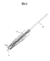
- FIG. 32 is a diagram showing an example of the configuration of the equipment shape measurement system 104 along the railway line in the second embodiment.
- the railway line equipment shape measurement system 104 includes a three-dimensional rail track database 108, a train formation information database 180, a movement amount estimation processing unit 183, a railway line equipment shape measurement processing unit 109, and a railway line equipment database 110.
- the three-dimensional shape of the equipment along the railway line is measured by the equipment shape measurement processing unit 109 along the railway line from the point cloud data of the equipment along the railway line, and recorded in the facility database 110 along the railway line.
- the movement amount estimation processing unit 183 can obtain the estimated train movement amount 184 based on the surrounding environment observation data 182 and the equipment information 136 along the railway line.
- the railway line equipment shape measurement processing unit 109 detects the railway line equipment in the surrounding environment observation data 182 from the rail shape model 134, the train formation information 181 and the estimated train movement amount 184, and the railway line equipment information 135, and three-dimensionally the railway line equipment. You can create a shape model.
- the railway line equipment shape measurement processing unit 109 uses sensors installed in front of the railway line. The time from observing the equipment to observing the same equipment along the railway line with a sensor installed behind can be calculated and used for detecting the equipment along the railway line in the surrounding environment observation data 182.
- the railway line equipment shape measurement system obtains the three-dimensional shape of the railway line equipment by superimposing a plurality of ambient environment observation data including the railway line equipment that is presumed to be the same from the train speed and the train length. More specifically, the equipment shape measurement system along the railway line estimates the same thing based on the speed of the train, the track of the rail, and the formation of the train.
- the present invention is not limited to the above-described embodiment, but includes various modifications.
- the above-described embodiment has been described in detail in order to explain the present invention in an easy-to-understand manner, and is not necessarily limited to the one including all the described configurations.
- it is possible to replace a part of the configuration of one embodiment with the configuration of another embodiment and it is also possible to add the configuration of another embodiment to the configuration of one embodiment.
- Surrounding environment Data coordinate conversion processing unit 119 ... Surrounding environment map generation processing unit 120 ... Surrounding environment map database 121 ... Scan matching self-position estimation processing unit 123 ... Detection range setting database 130 ... Surrounding environment observation data 131 ⁇ ⁇ ⁇ Ambient environment measurement data 132 ⁇ ⁇ ⁇ Rail measurement data 133 ⁇ ⁇ ⁇ Position / attitude information of transportation vehicle 134 ⁇ ⁇ ⁇ Rail shape model 135 ⁇ ⁇ ⁇ Railway equipment information 136 ⁇ ⁇ ⁇ railway equipment information 137 ⁇ ⁇ Rail position information 138 ⁇ ⁇ ⁇ Obstacle detection range 139 ⁇ ⁇ ⁇ Side boundary detection area 140 ⁇ ⁇ ⁇ Front boundary detection area 141 ⁇ ⁇ ⁇ Side detection target information 142 ⁇ ⁇ ⁇ Front detection target information 143 ⁇ ⁇ Side boundary monitoring result 144 ⁇ ⁇ ⁇ Front boundary monitoring result 145 ⁇ ⁇ ⁇ Obstacle detection information 146 ⁇ ⁇ ⁇ Transportation vehicle control drive command
- Surrounding environment measurement data 152 ... Surrounding environment measurement data 153 ; Surrounding environment map data 155 ... Lateral boundary detection area 156 ... Front boundary detection area 171 ... Line equipment 172. ⁇ ⁇ Equipment measurement data along the railway line 173 ⁇ ⁇ ⁇ Ambient environment measurement data set on the rail track Origin 180 ⁇ ⁇ ⁇ Train formation information database 181 ⁇ ⁇ ⁇ Train formation information 182 ⁇ ⁇ ⁇ Surrounding environment observation data 183 ⁇ ⁇ ⁇ Movement amount Estimated processing unit 184 ... Estimated train movement amount 185 ... Rail track
Abstract
Description
まず、図3を用いて、軌道輸送システム100の構成と各構成要素の役割を説明する。 (Structure of
First, the configuration of the
以上が、軌道輸送システム100の構成と各構成要素の役割の説明である。 Further,
The above is an explanation of the configuration of the
次に障害物検知システム103の動作を説明する。図5は、障害物検知システム103により実行される処理手順の一例を示すフローチャートである。 (Operation of obstacle detection system 103)
Next, the operation of the
以上が、障害物検知システム103の動作の説明である。 In
The above is a description of the operation of the
次に自己位置推定システム101の動作を説明する。図8は、自己位置推定システム101により実行される処理手順の一例を示すフローチャートである。 (Operation of self-position estimation system 101)
Next, the operation of the self-
以上が、自己位置推定システム101の動作の説明である。 When the vehicle does not travel along a specific track like an automobile, as shown in FIGS. 15 and 16, the ambient
The above is a description of the operation of the self-
次に沿線設備形状計測システム104の動作を説明する。図17は、沿線設備形状計測システム104により実行される処理手順の一例を示すフローチャートである。 (Operation of equipment
Next, the operation of the equipment
以上が、沿線設備形状計測システム104の動作の説明である。 In
The above is a description of the operation of the equipment
次に、輸送用車両運転制御部105の動作を説明する。図31は、輸送用車両運転制御部により実行される処理手順の一例を示すフローチャートである。ここでは、障害物検知情報145が、輸送用車両102の制動の必要性に関する情報を含み、輸送用車両運転制御部が、障害物検知情報145に基づき輸送用車両102の制駆動を制御する例を説明する。 (Operation of transport vehicle operation control unit 105)
Next, the operation of the transport vehicle
以上が、輸送用車両運転制御部105の動作の説明である。 In
The above is a description of the operation of the transportation vehicle
101・・・自己位置推定システム
102・・・輸送用車両
103・・・障害物検知システム
104・・・沿線設備形状計測システム
105・・・輸送用車両運転制御部
106・・・輸送用車両制駆動部
107・・・周囲環境観測部
108・・・3次元レール軌道データベース
109・・・沿線設備形状計測処理部
110・・・沿線設備データベース
111・・・監視エリア設定処理部
112・・・検知対象情報データベース
113・・・前方境界監視部
114・・・側方境界監視部
115・・・障害物検知部
116・・・観測データ選別処理部
117・・・車両姿勢推定処理部
118・・・周囲環境データ座標変換処理部
119・・・周囲環境地図生成処理部
120・・・周囲環境地図データベース
121・・・スキャンマッチング自己位置推定処理部
123・・・検知範囲設定データベース
130・・・周囲環境観測データ
131・・・周囲環境計測データ
132・・・レール計測データ
133・・・輸送用車両の位置・姿勢情報
134・・・レール形状モデル
135・・・沿線設備情報
136・・・沿線設備情報
137・・・レール位置情報
138・・・障害物検知範囲
139・・・側方境界検出領域
140・・・前方境界検出領域
141・・・側方検知対象情報
142・・・前方検知対象情報
143・・・側方境界監視結果
144・・・前方境界監視結果
145・・・障害物検知情報
146・・・輸送用車両制駆動指令
147・・・レール観測データ
149・・・車両姿勢
150・・・車両姿勢
151・・・周囲環境計測データ
152・・・周囲環境計測データ
153・・・周囲環境地図データ
155・・・側方境界検出領域
156・・・前方境界検出領域
171・・・沿線設備
172・・・沿線設備計測データ
173・・・レール軌道上に設定した周囲環境計測データ原点
180・・・列車編成情報データベース
181・・・列車編成情報
182・・・周囲環境観測データ
183・・・移動量推定処理部
184・・・推定列車移動量
185・・・レール軌道 100 ... Orbital transportation system
101 ... Self-position estimation system
102 ... Transportation vehicle
103 ... Obstacle detection system
104: Equipment shape measurement system along the railway line 105: Transportation vehicle operation control unit
106 ... Transportation vehicle control drive unit
107 ・ ・ ・ Ambient
Claims (15)
- 列車に設置され、既知の沿線設備を含む列車走行中の周囲環境を観測して周囲環境観測データを取得する周囲環境観測部と、
軌道上の複数の位置で取得した前記沿線設備を含む複数の前記周囲環境観測データをレールの軌道に基づいて重ね合わせて前記沿線設備の3次元形状を求める沿線設備形状計測システムと、
を備える軌道輸送システム。 The Surrounding Environment Observation Department, which is installed on the train and observes the surrounding environment while the train is running, including known equipment along the railway line, and acquires the surrounding environment observation data.
A railway line equipment shape measurement system that obtains the three-dimensional shape of the railway line equipment by superimposing a plurality of the ambient environment observation data including the railway line equipment acquired at a plurality of positions on the track based on the rail track.
Orbital transportation system equipped with. - 請求項1に記載の軌道輸送システムであって、
前記沿線設備形状計測システムは、前記周囲環境観測データに含まれる前記レールの観測データと前記レールの形状モデルとのマッチングおよび前記周囲環境観測データに含まれる前記沿線設備の計測データと前記沿線設備の形状とのマッチングに基づいて、前記沿線設備を含む複数の前記周囲環境観測データを重ね合わせて前記沿線設備の3次元形状を求める、
軌道輸送システム。 The orbital transportation system according to claim 1.
The railway line equipment shape measurement system matches the observation data of the rail included in the ambient environment observation data with the shape model of the rail, and the measurement data of the railway line equipment included in the ambient environment observation data and the railway line equipment. Based on the matching with the shape, the three-dimensional shape of the railway line equipment is obtained by superimposing a plurality of the surrounding environment observation data including the railway line facility.
Orbital transportation system. - 請求項1または請求項2に記載の軌道輸送システムであって、
前記周囲環境観測部は、前記列車の前方と後方に設置される、
軌道輸送システム。 The orbital transportation system according to claim 1 or 2.
The ambient environment observation unit is installed in front of and behind the train.
Orbital transportation system. - 請求項3に記載の軌道輸送システムであって、
前記沿線設備形状計測システムは、前記列車の速度と前記列車の長さから同一物と推測される前記沿線設備を含む複数の前記周囲環境観測データを重ね合わせて前記沿線設備の3次元形状を求める、
軌道輸送システム。 The orbital transportation system according to claim 3.
The railway line equipment shape measurement system obtains a three-dimensional shape of the railway line equipment by superimposing a plurality of ambient environment observation data including the railway line equipment that is presumed to be the same from the train speed and the train length. ,
Orbital transportation system. - 請求項4に記載の軌道輸送システムであって、
前記沿線設備形状計測システムは、前記列車の速度と前記レールの軌道と前記列車の編成に基づいて、前記同一物を推測する、
軌道輸送システム。 The orbital transportation system according to claim 4.
The equipment shape measuring system along the railway line estimates the same thing based on the speed of the train, the track of the rail, and the formation of the train.
Orbital transportation system. - 列車に設置される周囲環境観測部と、沿線設備形状計測システムと、を備える軌道輸送システムの制御方法であって、
周囲環境観測部が、既知の沿線設備を含む列車走行中の周囲環境を観測して周囲環境観測データを取得するステップと、
沿線設備形状計測システムが、軌道上の複数の位置で取得した前記沿線設備を含む複数の前記周囲環境観測データをレールの軌道に基づいて重ね合わせて前記沿線設備の3次元形状を求めるステップと、
を有する軌道輸送システムの制御方法。 It is a control method of an orbital transportation system equipped with an ambient environment observation unit installed on a train and a facility shape measurement system along the railway line.
The step that the surrounding environment observation department observes the surrounding environment while the train is running, including the known equipment along the railway line, and acquires the surrounding environment observation data.
The step of obtaining the three-dimensional shape of the railway line equipment by superimposing the plurality of ambient environment observation data including the railway line equipment acquired at a plurality of positions on the track by the railway line equipment shape measurement system based on the rail track.
A method of controlling an orbital transportation system. - 請求項6に記載の軌道輸送システムの制御方法であって、
前記沿線設備の3次元形状を求めるステップは、前記周囲環境観測データに含まれる前記レールの観測データと前記レールの形状モデルとのマッチングおよび前記周囲環境観測データに含まれる前記沿線設備の計測データと前記沿線設備の形状とのマッチングに基づいて、前記沿線設備を含む複数の前記周囲環境観測データを重ね合わせて前記沿線設備の3次元形状を求めるステップである、
軌道輸送システムの制御方法。 The control method for the orbital transportation system according to claim 6.
The step of obtaining the three-dimensional shape of the equipment along the railway line is to match the observation data of the rail included in the observation data of the surrounding environment with the shape model of the rail and the measurement data of the equipment along the railway line included in the observation data of the surrounding environment. This is a step of superimposing a plurality of the surrounding environment observation data including the railway line equipment to obtain a three-dimensional shape of the railway line equipment based on matching with the shape of the railway line equipment.
How to control the orbital transportation system. - 請求項6または請求項7に記載の軌道輸送システムの制御方法であって、
前記周囲環境観測部は、前記列車の前方と後方に設置される、
軌道輸送システムの制御方法。 The control method for the orbital transportation system according to claim 6 or 7.
The ambient environment observation unit is installed in front of and behind the train.
How to control the orbital transportation system. - 請求項8に記載の軌道輸送システムの制御方法であって、
前記沿線設備の3次元形状を求めるステップは、前記列車の速度と前記列車の長さから同一物と推測される前記沿線設備を含む複数の前記周囲環境観測データを重ね合わせて前記沿線設備の3次元形状を求めるステップである、
軌道輸送システムの制御方法。 The control method for the orbital transportation system according to claim 8.
The step of obtaining the three-dimensional shape of the railway line equipment is to superimpose a plurality of the surrounding environment observation data including the railway line equipment which is presumed to be the same from the speed of the train and the length of the train, and to perform 3 of the railway line equipment. It is a step to find the dimensional shape,
How to control the orbital transportation system. - 請求項9に記載の軌道輸送システムの制御方法であって、
前記沿線設備の3次元形状を求めるステップは、前記列車の速度と前記レールの軌道と前記列車の編成に基づいて、前記同一物を推測するステップである、
軌道輸送システムの制御方法。 The control method for the orbital transportation system according to claim 9.
The step of obtaining the three-dimensional shape of the equipment along the railway line is a step of estimating the same thing based on the speed of the train, the track of the rail, and the formation of the train.
How to control the orbital transportation system. - 軌道上の複数の位置で取得した既知の沿線設備を含む複数の周囲環境観測データをレールの軌道に基づいて重ね合わせて前記沿線設備の3次元形状を求める、
沿線設備形状計測システム。 A three-dimensional shape of the equipment along the railway line is obtained by superimposing a plurality of ambient environment observation data including known equipment along the railway line acquired at a plurality of positions on the track based on the track of the rail.
Equipment shape measurement system along the railway line. - 請求項11に記載の沿線設備形状計測システムであって、
前記周囲環境観測データに含まれる前記レールの観測データと前記レールの形状モデルとのマッチングおよび前記周囲環境観測データに含まれる前記沿線設備の計測データと前記沿線設備の形状とのマッチングに基づいて、前記沿線設備を含む複数の前記周囲環境観測データを重ね合わせて前記沿線設備の3次元形状を求める、
沿線設備形状計測システム。 The equipment shape measurement system along the railway line according to claim 11.
Based on the matching between the observation data of the rail included in the ambient environment observation data and the shape model of the rail, and the matching of the measurement data of the equipment along the railway line and the shape of the equipment along the railway line included in the ambient environment observation data. The three-dimensional shape of the equipment along the railway line is obtained by superimposing a plurality of observation data of the surrounding environment including the equipment along the railway line.
Equipment shape measurement system along the railway line. - 請求項11または請求項12に記載の沿線設備形状計測システムであって、
前記周囲環境観測データは、列車の前方と後方に設置される周囲環境観測部により取得される、
沿線設備形状計測システム。 The equipment shape measurement system along the railway line according to claim 11 or 12.
The ambient environment observation data is acquired by the ambient environment observation unit installed in front of and behind the train.
Equipment shape measurement system along the railway line. - 請求項13に記載の沿線設備形状計測システムであって、
前記列車の速度と前記列車の長さから同一物と推測される前記沿線設備を含む複数の前記周囲環境観測データを重ね合わせて前記沿線設備の3次元形状を求める、
沿線設備形状計測システム。 The equipment shape measurement system along the railway line according to claim 13.
A three-dimensional shape of the equipment along the railway line is obtained by superimposing a plurality of observation data of the surrounding environment including the equipment along the railway line, which is presumed to be the same from the speed of the train and the length of the train.
Equipment shape measurement system along the railway line. - 請求項14に記載の沿線設備形状計測システムであって、
前記列車の速度と前記レールの軌道と前記列車の編成に基づいて、前記同一物を推測する、
沿線設備形状計測システム。 The equipment shape measurement system along the railway line according to claim 14.
Guess the same thing based on the speed of the train, the track of the rail, and the formation of the train.
Equipment shape measurement system along the railway line.
Priority Applications (3)
| Application Number | Priority Date | Filing Date | Title |
|---|---|---|---|
| EP21885936.1A EP4238852A1 (en) | 2020-10-28 | 2021-10-15 | Rail transportation system, method for controlling rail transportation system, and trackside facility shape measurement system |
| AU2021371394A AU2021371394B2 (en) | 2020-10-28 | 2021-10-15 | Rail transportation system, method for controlling rail transportation system, and trackside facility shape measurement system |
| US18/250,588 US20230415800A1 (en) | 2020-10-28 | 2021-10-15 | Rail transportation system, method for controlling rail transportation system, and trackside facility shape measurement system |
Applications Claiming Priority (2)
| Application Number | Priority Date | Filing Date | Title |
|---|---|---|---|
| JP2020180352A JP7461275B2 (en) | 2020-10-28 | 2020-10-28 | Track transportation system, control method for track transportation system, and trackside equipment shape measurement system |
| JP2020-180352 | 2020-10-28 |
Publications (1)
| Publication Number | Publication Date |
|---|---|
| WO2022091817A1 true WO2022091817A1 (en) | 2022-05-05 |
Family
ID=81382608
Family Applications (1)
| Application Number | Title | Priority Date | Filing Date |
|---|---|---|---|
| PCT/JP2021/038244 WO2022091817A1 (en) | 2020-10-28 | 2021-10-15 | Rail transportation system, method for controlling rail transportation system, and trackside facility shape measurement system |
Country Status (5)
| Country | Link |
|---|---|
| US (1) | US20230415800A1 (en) |
| EP (1) | EP4238852A1 (en) |
| JP (1) | JP7461275B2 (en) |
| AU (1) | AU2021371394B2 (en) |
| WO (1) | WO2022091817A1 (en) |
Citations (4)
| Publication number | Priority date | Publication date | Assignee | Title |
|---|---|---|---|---|
| WO2008099915A1 (en) | 2007-02-16 | 2008-08-21 | Mitsubishi Electric Corporation | Road/feature measuring device, feature identifying device, road/feature measuring method, road/feature measuring program, measuring device, measuring method, measuring program, measured position data, measuring terminal, measuring server device, drawing device, drawing method, drawing program, and drawing data |
| JP2017001638A (en) | 2015-06-16 | 2017-01-05 | 西日本旅客鉄道株式会社 | Train position detection system using image processing, and train position and environmental change detection system using image processing |
| JP2017196948A (en) | 2016-04-26 | 2017-11-02 | 株式会社明電舎 | Three-dimensional measurement device and three-dimensional measurement method for train facility |
| WO2019138716A1 (en) * | 2018-01-10 | 2019-07-18 | 株式会社日立製作所 | Image compositing system and image compositing method |
-
2020
- 2020-10-28 JP JP2020180352A patent/JP7461275B2/en active Active
-
2021
- 2021-10-15 EP EP21885936.1A patent/EP4238852A1/en active Pending
- 2021-10-15 AU AU2021371394A patent/AU2021371394B2/en active Active
- 2021-10-15 US US18/250,588 patent/US20230415800A1/en active Pending
- 2021-10-15 WO PCT/JP2021/038244 patent/WO2022091817A1/en active Application Filing
Patent Citations (4)
| Publication number | Priority date | Publication date | Assignee | Title |
|---|---|---|---|---|
| WO2008099915A1 (en) | 2007-02-16 | 2008-08-21 | Mitsubishi Electric Corporation | Road/feature measuring device, feature identifying device, road/feature measuring method, road/feature measuring program, measuring device, measuring method, measuring program, measured position data, measuring terminal, measuring server device, drawing device, drawing method, drawing program, and drawing data |
| JP2017001638A (en) | 2015-06-16 | 2017-01-05 | 西日本旅客鉄道株式会社 | Train position detection system using image processing, and train position and environmental change detection system using image processing |
| JP2017196948A (en) | 2016-04-26 | 2017-11-02 | 株式会社明電舎 | Three-dimensional measurement device and three-dimensional measurement method for train facility |
| WO2019138716A1 (en) * | 2018-01-10 | 2019-07-18 | 株式会社日立製作所 | Image compositing system and image compositing method |
Also Published As
| Publication number | Publication date |
|---|---|
| AU2021371394A1 (en) | 2023-06-22 |
| AU2021371394B2 (en) | 2023-11-30 |
| EP4238852A1 (en) | 2023-09-06 |
| JP2022071407A (en) | 2022-05-16 |
| US20230415800A1 (en) | 2023-12-28 |
| JP7461275B2 (en) | 2024-04-03 |
Similar Documents
| Publication | Publication Date | Title |
|---|---|---|
| US11124207B2 (en) | Optical route examination system and method | |
| Bohren et al. | Little ben: The ben franklin racing team's entry in the 2007 DARPA urban challenge | |
| US11270130B2 (en) | Route inspection system | |
| CN112489416A (en) | Using information from traffic mirrors for automated driving | |
| WO2019244425A1 (en) | Obstacle detection system and obstacle detection method | |
| JP6090190B2 (en) | Mobile management device | |
| JP7181754B2 (en) | Obstacle detection system for track traveling vehicle and obstacle detection method | |
| WO2022091817A1 (en) | Rail transportation system, method for controlling rail transportation system, and trackside facility shape measurement system | |
| KR20230031344A (en) | System and Method for Detecting Obstacles in Area Surrounding Vehicle | |
| JP6052194B2 (en) | Mobile management device | |
| WO2021044707A1 (en) | Surroundings observation system, surroundings observation program, and surroundings observation method | |
| JP7348881B2 (en) | Obstacle detection system, obstacle detection method, and self-position estimation system | |
| US20220011774A1 (en) | Method for driverless transfer of a vehicle over a route within a closed area | |
| US10713503B2 (en) | Visual object detection system | |
| JP7132740B2 (en) | Object detection system | |
| KR102433595B1 (en) | Unmanned transportation apparatus based on autonomous driving for smart maintenance of railroad vehicles | |
| Franke et al. | Towards holistic autonomous obstacle detection in railways by complementing of on-board vision with UAV-based object localization | |
| US20210380119A1 (en) | Method and system for operating a mobile robot | |
| JP2020172230A (en) | Position detection method and position detection system | |
| JP7454522B2 (en) | Vehicle merging system | |
| US20240059310A1 (en) | Method for controlling drive-through and apparatus for controlling drive-through | |
| CN116700249A (en) | Shunting automatic driving method, system, equipment, storage medium and product thereof | |
| JP2022071407A5 (en) | ||
| JP2023007548A (en) | Image processing device and image processing method | |
| CN117642645A (en) | Method and positioning device for positioning a motor vehicle and motor vehicle |
Legal Events
| Date | Code | Title | Description |
|---|---|---|---|
| 121 | Ep: the epo has been informed by wipo that ep was designated in this application |
Ref document number: 21885936 Country of ref document: EP Kind code of ref document: A1 |
|
| DPE1 | Request for preliminary examination filed after expiration of 19th month from priority date (pct application filed from 20040101) | ||
| WWE | Wipo information: entry into national phase |
Ref document number: 2021371394 Country of ref document: AU |
|
| NENP | Non-entry into the national phase |
Ref country code: DE |
|
| ENP | Entry into the national phase |
Ref document number: 2021885936 Country of ref document: EP Effective date: 20230530 |
|
| ENP | Entry into the national phase |
Ref document number: 2021371394 Country of ref document: AU Date of ref document: 20211015 Kind code of ref document: A |