WO2022091717A1 - Arc detection system, arc detection method, and program - Google Patents
Arc detection system, arc detection method, and program Download PDFInfo
- Publication number
- WO2022091717A1 WO2022091717A1 PCT/JP2021/036857 JP2021036857W WO2022091717A1 WO 2022091717 A1 WO2022091717 A1 WO 2022091717A1 JP 2021036857 W JP2021036857 W JP 2021036857W WO 2022091717 A1 WO2022091717 A1 WO 2022091717A1
- Authority
- WO
- WIPO (PCT)
- Prior art keywords
- arc
- power supply
- supply path
- acquisition unit
- occurred
- Prior art date
Links
- 238000001514 detection method Methods 0.000 title claims abstract description 102
- 238000004891 communication Methods 0.000 claims abstract description 75
- 238000005259 measurement Methods 0.000 claims abstract description 47
- 230000005856 abnormality Effects 0.000 claims description 26
- 230000008901 benefit Effects 0.000 description 11
- 244000145845 chattering Species 0.000 description 10
- 230000000052 comparative effect Effects 0.000 description 10
- 238000000034 method Methods 0.000 description 7
- 230000008569 process Effects 0.000 description 6
- 238000012986 modification Methods 0.000 description 4
- 230000004048 modification Effects 0.000 description 4
- 238000005070 sampling Methods 0.000 description 4
- 238000010586 diagram Methods 0.000 description 3
- 238000010891 electric arc Methods 0.000 description 3
- 230000004044 response Effects 0.000 description 3
- 239000004065 semiconductor Substances 0.000 description 3
- 238000001228 spectrum Methods 0.000 description 3
- 239000004020 conductor Substances 0.000 description 2
- 230000006866 deterioration Effects 0.000 description 2
- 238000003780 insertion Methods 0.000 description 2
- 230000037431 insertion Effects 0.000 description 2
- 238000012545 processing Methods 0.000 description 2
- 230000005540 biological transmission Effects 0.000 description 1
- 238000006243 chemical reaction Methods 0.000 description 1
- 239000000284 extract Substances 0.000 description 1
- 230000001788 irregular Effects 0.000 description 1
- 239000000463 material Substances 0.000 description 1
- 238000012544 monitoring process Methods 0.000 description 1
- 230000001131 transforming effect Effects 0.000 description 1
Images


Classifications
-
- H—ELECTRICITY
- H04—ELECTRIC COMMUNICATION TECHNIQUE
- H04B—TRANSMISSION
- H04B3/00—Line transmission systems
- H04B3/54—Systems for transmission via power distribution lines
-
- G—PHYSICS
- G01—MEASURING; TESTING
- G01R—MEASURING ELECTRIC VARIABLES; MEASURING MAGNETIC VARIABLES
- G01R31/00—Arrangements for testing electric properties; Arrangements for locating electric faults; Arrangements for electrical testing characterised by what is being tested not provided for elsewhere
- G01R31/08—Locating faults in cables, transmission lines, or networks
- G01R31/081—Locating faults in cables, transmission lines, or networks according to type of conductors
- G01R31/086—Locating faults in cables, transmission lines, or networks according to type of conductors in power transmission or distribution networks, i.e. with interconnected conductors
-
- G—PHYSICS
- G01—MEASURING; TESTING
- G01R—MEASURING ELECTRIC VARIABLES; MEASURING MAGNETIC VARIABLES
- G01R31/00—Arrangements for testing electric properties; Arrangements for locating electric faults; Arrangements for electrical testing characterised by what is being tested not provided for elsewhere
- G01R31/12—Testing dielectric strength or breakdown voltage ; Testing or monitoring effectiveness or level of insulation, e.g. of a cable or of an apparatus, for example using partial discharge measurements; Electrostatic testing
- G01R31/1227—Testing dielectric strength or breakdown voltage ; Testing or monitoring effectiveness or level of insulation, e.g. of a cable or of an apparatus, for example using partial discharge measurements; Electrostatic testing of components, parts or materials
- G01R31/1263—Testing dielectric strength or breakdown voltage ; Testing or monitoring effectiveness or level of insulation, e.g. of a cable or of an apparatus, for example using partial discharge measurements; Electrostatic testing of components, parts or materials of solid or fluid materials, e.g. insulation films, bulk material; of semiconductors or LV electronic components or parts; of cable, line or wire insulation
-
- G—PHYSICS
- G01—MEASURING; TESTING
- G01R—MEASURING ELECTRIC VARIABLES; MEASURING MAGNETIC VARIABLES
- G01R31/00—Arrangements for testing electric properties; Arrangements for locating electric faults; Arrangements for electrical testing characterised by what is being tested not provided for elsewhere
- G01R31/12—Testing dielectric strength or breakdown voltage ; Testing or monitoring effectiveness or level of insulation, e.g. of a cable or of an apparatus, for example using partial discharge measurements; Electrostatic testing
- G01R31/14—Circuits therefor, e.g. for generating test voltages, sensing circuits
-
- H—ELECTRICITY
- H02—GENERATION; CONVERSION OR DISTRIBUTION OF ELECTRIC POWER
- H02H—EMERGENCY PROTECTIVE CIRCUIT ARRANGEMENTS
- H02H1/00—Details of emergency protective circuit arrangements
- H02H1/0007—Details of emergency protective circuit arrangements concerning the detecting means
- H02H1/0015—Using arc detectors
-
- H—ELECTRICITY
- H02—GENERATION; CONVERSION OR DISTRIBUTION OF ELECTRIC POWER
- H02H—EMERGENCY PROTECTIVE CIRCUIT ARRANGEMENTS
- H02H3/00—Emergency protective circuit arrangements for automatic disconnection directly responsive to an undesired change from normal electric working condition with or without subsequent reconnection ; integrated protection
- H02H3/46—Emergency protective circuit arrangements for automatic disconnection directly responsive to an undesired change from normal electric working condition with or without subsequent reconnection ; integrated protection responsive to frequency deviations
-
- H—ELECTRICITY
- H02—GENERATION; CONVERSION OR DISTRIBUTION OF ELECTRIC POWER
- H02J—CIRCUIT ARRANGEMENTS OR SYSTEMS FOR SUPPLYING OR DISTRIBUTING ELECTRIC POWER; SYSTEMS FOR STORING ELECTRIC ENERGY
- H02J1/00—Circuit arrangements for dc mains or dc distribution networks
- H02J1/06—Two-wire systems
-
- H—ELECTRICITY
- H02—GENERATION; CONVERSION OR DISTRIBUTION OF ELECTRIC POWER
- H02J—CIRCUIT ARRANGEMENTS OR SYSTEMS FOR SUPPLYING OR DISTRIBUTING ELECTRIC POWER; SYSTEMS FOR STORING ELECTRIC ENERGY
- H02J13/00—Circuit arrangements for providing remote indication of network conditions, e.g. an instantaneous record of the open or closed condition of each circuitbreaker in the network; Circuit arrangements for providing remote control of switching means in a power distribution network, e.g. switching in and out of current consumers by using a pulse code signal carried by the network
- H02J13/00002—Circuit arrangements for providing remote indication of network conditions, e.g. an instantaneous record of the open or closed condition of each circuitbreaker in the network; Circuit arrangements for providing remote control of switching means in a power distribution network, e.g. switching in and out of current consumers by using a pulse code signal carried by the network characterised by monitoring
-
- H—ELECTRICITY
- H02—GENERATION; CONVERSION OR DISTRIBUTION OF ELECTRIC POWER
- H02J—CIRCUIT ARRANGEMENTS OR SYSTEMS FOR SUPPLYING OR DISTRIBUTING ELECTRIC POWER; SYSTEMS FOR STORING ELECTRIC ENERGY
- H02J13/00—Circuit arrangements for providing remote indication of network conditions, e.g. an instantaneous record of the open or closed condition of each circuitbreaker in the network; Circuit arrangements for providing remote control of switching means in a power distribution network, e.g. switching in and out of current consumers by using a pulse code signal carried by the network
- H02J13/00006—Circuit arrangements for providing remote indication of network conditions, e.g. an instantaneous record of the open or closed condition of each circuitbreaker in the network; Circuit arrangements for providing remote control of switching means in a power distribution network, e.g. switching in and out of current consumers by using a pulse code signal carried by the network characterised by information or instructions transport means between the monitoring, controlling or managing units and monitored, controlled or operated power network element or electrical equipment
- H02J13/00007—Circuit arrangements for providing remote indication of network conditions, e.g. an instantaneous record of the open or closed condition of each circuitbreaker in the network; Circuit arrangements for providing remote control of switching means in a power distribution network, e.g. switching in and out of current consumers by using a pulse code signal carried by the network characterised by information or instructions transport means between the monitoring, controlling or managing units and monitored, controlled or operated power network element or electrical equipment using the power network as support for the transmission
-
- G—PHYSICS
- G01—MEASURING; TESTING
- G01R—MEASURING ELECTRIC VARIABLES; MEASURING MAGNETIC VARIABLES
- G01R31/00—Arrangements for testing electric properties; Arrangements for locating electric faults; Arrangements for electrical testing characterised by what is being tested not provided for elsewhere
- G01R31/50—Testing of electric apparatus, lines, cables or components for short-circuits, continuity, leakage current or incorrect line connections
- G01R31/58—Testing of lines, cables or conductors
-
- H—ELECTRICITY
- H04—ELECTRIC COMMUNICATION TECHNIQUE
- H04B—TRANSMISSION
- H04B2203/00—Indexing scheme relating to line transmission systems
- H04B2203/54—Aspects of powerline communications not already covered by H04B3/54 and its subgroups
- H04B2203/5462—Systems for power line communications
- H04B2203/5495—Systems for power line communications having measurements and testing channel
-
- H—ELECTRICITY
- H04—ELECTRIC COMMUNICATION TECHNIQUE
- H04B—TRANSMISSION
- H04B3/00—Line transmission systems
- H04B3/02—Details
- H04B3/46—Monitoring; Testing
Definitions
- the present invention relates to an arc detection system, an arc detection method, and a program for determining whether or not an arc failure may occur in a power supply path.
- Patent Document 1 discloses an arc detecting means for detecting an arc.
- This arc detecting means includes a voltage detecting means for measuring the voltage value between the input side wiring to the terminal block and the output side wiring from the terminal block, and a current detecting means for measuring the current value of the output side wiring from the terminal block. Means and.
- the arc detection means simultaneously detects fluctuations in the voltage value of the voltage detection means and fluctuations in the current value of the current detection means to distinguish between electrical noise and the like and the arc in the terminal block.
- the present invention provides an arc detection system, an arc detection method, and a program that can easily prevent erroneous detection of the occurrence of an arc failure.
- the arc detection system includes a first acquisition unit, a second acquisition unit, and a determination unit.
- the first acquisition unit acquires a measurement result of a current flowing through a power supply path to which power is supplied from a power source or a voltage in the power supply path.
- the second acquisition unit acquires quality information regarding the quality of communication with the device by performing power line communication with the device connected to the power supply path via the power supply path.
- the determination unit has an arc failure in the power supply path based on the component of a specific frequency band in the measurement results acquired by the first acquisition unit and the quality information acquired by the second acquisition unit. Judges whether or not has occurred.
- the arc detection method includes a first acquisition step, a second acquisition step, and a determination step.
- the first acquisition step the measurement result of the current flowing through the power supply path to which power is supplied from the power supply or the voltage in the power supply path is acquired.
- the second acquisition step quality information regarding the quality of communication with the device is acquired by performing power line communication with the device connected to the power supply path via the power supply path.
- an arc failure occurs in the power supply path based on the component of a specific frequency band in the measurement results acquired in the first acquisition step and the quality information acquired in the second acquisition step. Judges whether or not has occurred.
- the program according to one aspect of the present invention causes one or more processors to execute the arc detection method.
- FIG. 1 is a schematic diagram showing an overall configuration including an arc detection system according to an embodiment.
- FIG. 2A is a timing chart showing a first determination example by the determination unit of the arc detection system according to the embodiment.
- FIG. 2B is a timing chart showing a second determination example by the determination unit of the arc detection system according to the embodiment.
- FIG. 2C is a timing chart showing a third determination example by the determination unit of the arc detection system according to the embodiment.
- FIG. 3 is a flowchart showing an operation example of the arc detection system according to the embodiment.
- FIG. 1 is a schematic diagram showing an overall configuration including an arc detection system 100 according to an embodiment.
- the arc detection system 100 is a system for determining whether or not an arc failure has occurred in the power supply path L1 to which power is mainly supplied from the power supply 2. That is, the power supply path L1 may be damaged or broken due to, for example, an external factor or aged deterioration, and an arc (arc discharge) is generated due to such damage, resulting in an arc failure. there's a possibility that. Therefore, the arc detection system 100 is mainly used for detecting an arc failure that may occur in the feeding path L1.
- the arc detection system 100 is used for a so-called DC (Direct Current) distribution network 200.
- the DC distribution network 200 is configured to include one or more power supply paths L1. In FIG. 1, only one power supply path L1 is shown. DC power is supplied to the DC distribution network 200 from the power source (here, DC power source) 2.
- Each power supply path L1 is composed of a pair of electric circuits, that is, a positive power supply path connected to the positive electrode on the output side of the power supply 2 and a negative power supply path connected to the negative electrode on the output side of the power supply 2.
- DC power is supplied from the power supply 2 to this power supply path L1.
- the DC distribution network 200 has a plurality of power supply paths L1, one end of each of the plurality of power supply paths L1 is connected to one or more branch points. Therefore, when DC power is supplied from the power source 2 to any of the power supply paths L1, DC power is also supplied to the other power supply paths L1 via one or more branch points.
- the power supply 2 is a power converter provided with an AC / DC converter 21.
- the power supply 2 converts the AC power output from the power system 300 into DC power, and outputs the converted DC power to the power supply path L1 to which the power supply 2 is connected.
- the DC distribution network 200 has a plurality of power supply paths L1
- the DC power output to the power supply path L1 is also output to the other power supply paths L1.
- the power source 2 may be a mode that outputs DC power, and may be a distributed power source such as a solar cell or a power source such as a storage battery, or a power source thereof and a power converter (for example, a DC / DC converter). It may be in combination with a power converter (with a circuit).
- Each power supply path L1 is composed of, for example, a duct rail, and one or more devices 3 can be attached to it. That is, in each power supply path L1, one or more devices 3 can be arranged at free positions. Of course, each power supply path L1 may have a mode in which a place where one or more devices 3 can be attached is predetermined. In the embodiment, each power supply path L1 is arranged on the ceiling of the facility, but may be arranged on the floor, wall, furniture, or the like of the facility.
- the device 3 has a load 31 and a pair of connection terminals. Further, the device 3 has a function of communicating with the second acquisition unit 12 (described later) of the arc detection system 100.
- the communication function is exhibited in a state where the device 3 is operating. That is, in the embodiment, when the device 3 is connected to the power supply path L1, the device 3 can communicate with the second acquisition unit 12, but when the device 3 is not connected to the power supply path L1, the device 3 can communicate. Cannot communicate with the second acquisition unit 12.
- the device 3 can be attached to or removed from the power supply path L1 via a pair of connection terminals. Specifically, when the device 3 is attached to the power supply path L1, the device 3 is rotated clockwise or viewed from the insertion direction of the device 3 with the pair of connection terminals of the device 3 inserted into the duct rail (power supply path L1). Rotate it counterclockwise by a predetermined angle (eg, 90 degrees). As a result, the pair of connection terminals are fixed in contact with the pair of connection conductors provided in the power supply path L1, and the device 3 is electrically and mechanically connected to the power supply path L1.
- a predetermined angle eg, 90 degrees
- the device 3 When the device 3 is removed from the power supply path L1, the device 3 is rotated by a predetermined angle in the opposite direction to the above when viewed from the insertion direction of the device 3. As a result, the contact state between the pair of connection terminals and the pair of connection conductors is released, so that the device 3 can be subsequently removed from the power supply path L1.
- the load 31 is driven by receiving DC power supplied from the power supply 2 via the power supply path L1 in a state where the device 3 is attached to the power supply path L1.
- the device 3 is a lighting fixture, but may be, for example, a speaker, a camera, a sensor, a USB PD (Power Delivery), or the like. That is, the device 3 may be a device other than the lighting fixture as long as the load 31 is driven by receiving electric power.
- all the devices 3 connected to each power supply path L1 are lighting fixtures and have one type, but there may be a plurality of types of devices 3 connected to each power supply path L1. ..
- a lighting fixture, a speaker, a camera, a sensor, and a USB PD may be connected to each power supply path L1. All of these devices 3 may be connected to one power supply path L1, or may be divided and connected to a plurality of power supply paths L1.
- the arc detection system 100 has a first acquisition unit 11, a second acquisition unit 12, a determination unit 13, a notification unit 14, and a stop unit as functional components for determining whether or not an arc failure has occurred. It is equipped with 15.
- the first acquisition unit 11, the determination unit 13, the notification unit 14, and the stop unit 15 are provided in the power supply 2.
- the second acquisition unit 12 is provided in the communication module 20 connected to the power supply path L1 separately from the power supply 2.
- the communication module 20 is configured to be able to communicate with the power source 2 by, for example, wireless communication or power line communication (PLC).
- the arc detection system 100 is, for example, a microcomputer or a device including a microcomputer.
- the microcomputer is a semiconductor integrated circuit having a ROM and RAM in which a program is stored, a processor (CPU: Central Processing Unit) for executing the program, a timer, an A / D converter, a D / A converter, and the like.
- the first acquisition unit 11, the second acquisition unit 12, the determination unit 13, the notification unit 14, and the stop unit 15 are all realized by the processor executing the above program.
- the first acquisition unit 11 acquires the measurement result of the current I1 flowing through the power supply path L1 to which power is supplied from the power supply 2 or the voltage V1 in the power supply path L1.
- the first acquisition unit 11 acquires the measurement result of the current I1 measured by sampling in a predetermined cycle (sampling cycle) with the ammeter 22. That is, the first acquisition unit 11 acquires the measurement result of the current I1 from the ammeter 22 at a predetermined cycle.
- the ammeter 22 is provided between the power supply 2 and the power supply path L1 and measures the current flowing in the negative power supply path of the power supply path L1 (that is, the current I1 flowing in the power supply path L1).
- the ammeter 22 may be built in the power supply 2.
- the second acquisition unit 12 acquires quality information regarding the quality of communication with the device 3 by performing power line communication with the device 3 connected to the power supply path L1 via the power supply path L1.
- the communication standard for power line communication between the second acquisition unit 12 and the device 3 is not particularly limited.
- the quality information includes the degree of quality of power line communication between the second acquisition unit 12 and the device 3, and the degree of quality of communication is represented by the frequency of communication abnormalities. That is, the second acquisition unit 12 acquires the frequency of communication abnormalities as quality information.
- the communication abnormality may include, for example, the inability to receive a signal unilaterally transmitted from the device 3, or the fact that even if the signal can be received, only a part of the data can be received.
- the communication abnormality is, for example, when a request signal including a command requesting a reply is transmitted from the second acquisition unit 12 to the device 3, the response signal from the device 3 to which the request signal is transmitted cannot be received or the response is received. It may include the fact that even if the signal can be received, only a part of the data can be received.
- the frequency of communication abnormalities is the number of occurrences of communication abnormalities per unit time (for example, 1 minute, several minutes, 1 hour, or several hours), or from the second acquisition unit 12 to the device 3 per unit time. Expressed by the number of request retries. That is, the smaller the frequency of communication abnormalities, the higher the degree of communication quality, and the higher the frequency of communication abnormalities, the lower the degree of communication quality.
- the second acquisition unit 12 communicates with the device 3 connected to the power supply path L1 and operating at a fixed cycle (for example, several hundred ms).
- the second acquisition unit 12 may communicate with the device 3 by receiving a signal unilaterally transmitted from the device 3 connected to the power supply path L1 and operating.
- the second acquisition unit 12 may communicate with the device 3 by broadcasting the request signal and receiving the response signal from the device 3 that has received the request signal.
- the signal transmitted from the device 3 to the second acquisition unit 12 includes the identification information of the source device 3. Therefore, the arc detection system 100 can grasp the quality information for each device 3.
- the determination unit 13 causes an arc failure in the power supply path L1 based on the component of a specific frequency band in the measurement results acquired by the first acquisition unit 11 and the quality information acquired by the second acquisition unit 12. Determine if it has been done. Specifically, the determination unit 13 frequency-analyzes the measurement result of the current I1 acquired by the first acquisition unit 11. The frequency analysis is to calculate the frequency spectrum of the measurement result of the current I1 by, for example, Fourier transforming (here, FFT (Fast Fourier Transform)) the time waveform of the measurement result of the current I1.
- FFT Fast Fourier Transform
- the determination unit 13 refers to the calculated frequency spectrum, and determines that an arc is generated when the measurement result of the current I1 contains a component of a specific frequency band of the first predetermined value or more.
- the specific frequency band is, for example, a band including the frequency of noise generated when an arc is generated.
- the specific frequency band is, for example, a tens of kHz band, which is a relatively high frequency band. The frequency of noise generated in the above cases can be obtained experimentally.
- the determination unit 13 not only determines whether or not an arc is generated based on the measurement result acquired by the first acquisition unit 11, but also refers to the quality information acquired by the second acquisition unit 12, so that the power supply path It is determined whether or not an arc failure has occurred in L1. That is, the determination unit 13 does not determine that an arc failure has occurred in the feeding path L1 simply by determining that an arc has occurred based on the measurement result acquired by the first acquisition unit 11.
- the process leading to the determination of the occurrence of the arc failure will be described.
- the arcs that can be generated in the DC distribution network 200 include an arc caused by a disconnection or a half disconnection of the power supply path L1 and an arc that can be instantaneously generated when the device 3 is attached to and detached from the power supply path L1. That is, when the device 3 is attached to the power supply path L1, if the device 3 is not smoothly attached, the load 31 of the device 3 is connected to the power supply path L1 and is disconnected from the power supply path L1. Is repeated in a short period of time, so-called chattering may occur. Then, during the chattering generation period, an arc may occur when the load 31 is momentarily disconnected from the feeding path L1 while the current is flowing.
- chattering may occur in the same manner as described above. Then, during the chattering generation period, an arc may occur when the load 31 is momentarily disconnected from the feeding path L1 while the current is flowing.
- the generation of an arc due to such chattering can occur not only in the DC distribution network 200 but also in the AC (Alternating Current) distribution network. In particular, if the device 3 is attached to the feeding path L1 while the distance between the electrode of the device 3 and the electrode of the feeding path L1 is halfway, the arc is less likely to disappear.
- the determination unit 13 can determine that an arc has occurred by monitoring a component of a specific frequency band of the current I1 (or voltage V1).
- a component of a specific frequency band is superimposed on the current I1 (or voltage V1).
- Such a phenomenon can occur not only in the DC distribution network 200 but also in the AC distribution network.
- an arc caused by a disconnection or a half disconnection of the feeding path L1 tends to cause an arc failure, but the above phenomenon is not caused by the generation of an arc in the feeding path L1 in the first place, and the arc failure occurs. It does not cause it. Further, since the arc caused by chattering basically disappears in a short period of time, it is unlikely to cause an arc failure. Therefore, the arc detection system 100 does not detect the above phenomenon and the short-time arc caused by chattering, and determines that the occurrence of an arc mainly caused by the disconnection or half disconnection of the power supply path L1 is the occurrence of an arc failure. It is desirable to do.
- the determination unit 13 determines whether or not an arc failure has occurred in the power supply path L1 as follows. That is, the determination unit 13 first determines whether or not an arc has occurred based on the measurement result acquired by the first acquisition unit 11. Then, when it is determined that an arc has occurred, the determination unit 13 monitors the duration of the determination that the arc has occurred. When the duration is less than the first threshold value, the determination unit 13 determines that no arc failure has occurred in the power supply path L1 regardless of the quality information acquired by the second acquisition unit 12.
- the determination unit 13 determines whether or not an arc failure has occurred in the feeding path L1 as in the first determination example or the second determination example shown below. Is determined. If the duration is equal to or longer than the second threshold value, the determination unit 13 determines whether or not an arc failure has occurred in the feeding path L1 as in the third determination example shown below.
- the first threshold and the second threshold are set in advance by, for example, the user of the arc detection system 100.
- FIG. 2A is a timing chart showing a first determination example by the determination unit 13 of the arc detection system 100 according to the embodiment.
- FIG. 2B is a timing chart showing a second determination example by the determination unit 13 of the arc detection system 100 according to the embodiment.
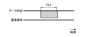
- FIG. 2C is a timing chart showing a third determination example by the determination unit 13 of the arc detection system 100 according to the embodiment.
- the pulse in the upper timing chart represents the duration of determination by the determination unit 13 that an arc has occurred.
- the pulse in the lower timing chart indicates that there was an abnormality in the power line communication between the second acquisition unit 12 and the device 3.
- the pulse is not shown because there is no abnormality in the power line communication between the second acquisition unit 12 and the device 3 as described later.
- the second acquisition unit 12 has not acquired or almost acquired the quality information indicating that there was an abnormality in the power line communication with the device 3. Not done. Therefore, in the first determination example, since the degree of communication quality of the determination unit 13 is high at the determination time t1, no arc is generated in the power supply path L1 and no arc failure occurs in the power supply path L1. , Is determined.
- the second acquisition unit 12 frequently acquires quality information indicating that there is an abnormality in the power line communication with the device 3. .. Therefore, in the second determination example, since the degree of communication quality of the determination unit 13 is small at the determination time t1, an arc due to a disconnection or a half disconnection in the power supply path L1 is generated, that is, an arc failure occurs. Is determined.
- the determination unit 13 determines that the arc has been generated based on the measurement result acquired by the first acquisition unit 11, and at the time of the determination, the second determination unit 2 If the degree of communication quality acquired by the acquisition unit 12 is small, it is determined that an arc failure has occurred.
- whether or not the degree of communication quality is low is determined by whether or not the frequency of communication abnormalities is equal to or higher than the threshold value.
- the determination unit 13 determines that the degree of communication quality is high if the frequency of communication abnormalities is less than the threshold value, and determines that the degree of communication quality is low if the frequency of communication abnormalities is equal to or higher than the threshold value. do.
- the threshold is preset, for example, by the user of the arc detection system 100.
- the term "at the time of determination” does not include only the moment of the determination time t1, but also includes a range from a time point before the determination time point t1 by a predetermined time to a time point after a predetermined time after the determination time point t1. You may go out.
- the second acquisition unit 12 does not acquire the quality information indicating that there is an abnormality in the power line communication with the device 3, but the arc by the determination unit 13 is generated.
- the duration of the determination that the occurrence has occurred is longer than the second threshold value (threshold time Th1). Therefore, in the third determination example, the determination unit 13 generates an arc due to a disconnection or a half disconnection in the power supply path L1 without referring to the quality information acquired by the second acquisition unit 12, that is, an arc failure. Is determined to have occurred.
- the determination unit 13 obtains the second acquisition. It is determined that an arc failure has occurred regardless of the quality information acquired by the unit 12.
- the notification unit 14 notifies the surroundings that an arc failure has occurred, for example, by turning on a lamp or sounding a buzzer. Further, the notification unit 14 may notify that an arc failure has occurred by transmitting information indicating that an arc failure has occurred to an information terminal owned by the owner or administrator of the arc detection system 100. ..
- the information terminal may include a personal computer or the like as well as a mobile terminal such as a smartphone or a tablet.
- the stop unit 15 stops the current flowing in the power supply path L1 when the determination unit 13 determines that an arc failure has occurred. As a result, if an arc discharge is generated due to an arc failure, the arc discharge disappears.
- the stop unit 15 stops the current flowing in the power supply path L1 by controlling the switch connected to the power supply path L1.
- the switch is, for example, a mechanical switch or a semiconductor switch.
- the mechanical switch is, for example, a switch such as a relay or a breaker
- the semiconductor switch is a switch such as a transistor or a diode.
- the switch connected to the power supply path L1 may be a switch directly connected to the power supply path L1 or a switch indirectly connected to the power supply path L1.
- the switch is a switch for realizing the AC / DC conversion function in the AC / DC converter 21. Even if the switch is not directly connected to the power supply path L1, it is indirectly connected to the power supply path L1, so that the switch is connected to the power supply path L1.
- the stop unit 15 controls the switch to stop the switching operation of the switch, thereby stopping the current flowing in the power supply path L1.
- the switch may be configured to switch the power supply 2 on and off.
- the stop unit 15 controls the switch to turn off the power supply 2 to stop the current flowing in the power supply path L1.
- the switch may be provided on the power supply path L1, and the switch may be configured to switch the opening and closing of the power supply path L1.
- the stop unit 15 may stop the current flowing in the power supply path L1 by controlling the switch to open the power supply path L1.
- FIG. 3 is a flowchart showing an operation example of the arc detection system 100 according to the embodiment.
- the first acquisition unit 11 acquires the measurement result of the current I1 from the ammeter 22 at a predetermined cycle (S1).
- the process S1 corresponds to the first acquisition step ST1 of the arc detection method.
- the second acquisition unit 12 acquires quality information from each device 3 by performing power line communication with each device 3 (S2).
- the process S2 corresponds to the second acquisition step ST2 of the arc detection method.
- the determination unit 13 first determines whether or not an arc has occurred based on the component of a specific frequency band in the measurement result of the current I1 acquired by the first acquisition unit 11 (S3).
- the determination unit 13 determines by frequency analysis of the measurement result of the current I1 acquired by the first acquisition unit 11.
- the determination unit 13 monitors the duration of the determination that an arc has occurred (S4). On the other hand, when the determination unit 13 determines that no arc has occurred (S3: No), the determination unit 13 determines that no arc failure has occurred (S7).
- the determination unit 13 determines that no arc failure has occurred (S7). If the duration is equal to or longer than the second threshold value (S4: No, S5: No), the determination unit 13 determines that an arc failure has occurred (S8). On the other hand, if the duration is equal to or longer than the first threshold value (S4: No) and less than the second threshold value (S5: Yes), the determination unit 13 obtains the quality information acquired by the second acquisition unit 12. With reference to it, it is monitored whether or not the degree of communication quality of each device 3 is small (that is, whether or not the frequency of communication abnormality is equal to or higher than the threshold value) at the determination time point t1 (S6).
- the determination unit 13 determines that no arc failure has occurred (S7). On the other hand, when the frequency of communication abnormality of any of the devices 3 is equal to or higher than the threshold value at the determination time point t1 (S6: No), the determination unit 13 determines that an arc failure has occurred (S8).
- the processes S3 to S8 correspond to the determination step ST3 of the arc detection method.
- the stop unit 15 stops the power supply from the power supply 2 to the power supply path L1 by stopping the current flowing through the power supply path L1 (S9). ). Then, the notification unit 14 notifies the occurrence of an arc failure (S10). On the other hand, when the determination unit 13 determines that no arc failure has occurred (S7), the processing of the arc detection system 100 ends. Hereinafter, the above series of processes S1 to S10 are repeated.
- the arc detection system of the comparative example is different from the arc detection system 100 according to the embodiment in that it does not include the second acquisition unit 12. That is, in the arc detection system of the comparative example, when the component of the specific frequency band in the measurement result of the current I1 acquired by the first acquisition unit 11 becomes the first predetermined value or more, the arc failure occurs immediately. It differs from the arc detection system 100 according to the embodiment in that it determines.
- the conditions required for the arc detection system will be explained. If an arc is generated due to a disconnection or half disconnection of the power supply path L1, if this state is left unattended, the disconnection or half disconnection may generate excessive heat, and in some cases, it may ignite, leading to a fire. be. Therefore, it is important for the arc detection system to detect the occurrence of an arc (that is, the occurrence of an arc failure) as soon as possible, and to stop the power supply to the power supply path L1 before a situation such as a fire occurs. For example, the UL (Underwriters Laboratories) standard requires that the occurrence of an arc failure be detected within 2 seconds after the occurrence of an arc.
- the arc detection system of the comparative example it is determined that an arc failure has occurred even when a steep fluctuation occurs in the load 31 of the device 3. That is, in the arc detection system of the comparative example, it is erroneously determined that an arc failure has occurred even when an arc has not actually occurred. As described above, in the arc detection system of the comparative example, it is determined that an arc failure has occurred every time an arc is generated and every time a steep fluctuation occurs in the load 31, so that the usability of the user may be deteriorated.
- an event such as notifying the user that an arc failure has occurred may occur, which is troublesome for the user. ..
- the power supply from the power supply 2 to the power supply path L1 is automatically stopped when it is determined that an arc failure has occurred.
- an event may occur in which the power supply to the power supply path L1 is stopped every time the device 3 is attached to or detached from the power supply path L1 and each time the power supply of the device 3 is turned on / off. Is also annoying to the user.
- the determination unit 13 can grasp the degree of quality of the power line communication with the device 3.
- the quality of the power line communication via the power supply path L1 is affected by the state of the power supply path L1. Specifically, if the power supply path L1 is not deteriorated, the quality of the power line communication is high, while if the power supply path L1 is deteriorated, the quality of the power line communication is low. Become. When the deterioration of the power supply path L1 progresses and a disconnection or a half disconnection occurs in a part, the degree of the quality of the power line communication becomes smaller as the frequency of communication abnormality becomes equal to or higher than the threshold value. That is, the determination unit 13 can determine whether or not a disconnection or a half disconnection is likely to occur in the power supply path L1 by grasping the degree of quality of the power line communication with the device 3.
- the arc detection system 100 it is determined that an arc failure has occurred when an arc is generated due to a disconnection or a half disconnection of the power supply path L1, and in other cases, the arc is basically performed. It is not determined that a failure has occurred.
- the arc detection system 100 it is unlikely that an arc failure has occurred when an arc due to chattering occurs or when a steep fluctuation occurs in the load 31.
- the arc detection system 100 it is possible to notify the user only when an arc failure which is considered to be an event having a particularly large influence on the user occurs, or to stop the power supply to the power supply path L1. , Has the advantage of being easy to use for the user.
- the ammeter 22 is a device different from the arc detection system 100, but it may be built in the arc detection system 100.
- the second acquisition unit 12 communicates with the device 3 connected to the power supply path L1 and operating at regular intervals, but the present invention is not limited to this.
- the second acquisition unit 12 may communicate with the device 3 irregularly. For example, as long as the number of times the second acquisition unit 12 transmits the request signal to the device 3 per unit time is constant, the transmission interval of the request signal may be irregular within the unit time.
- the arc detection system 100 is provided in the power supply 2, but the present invention is not limited to this.
- the arc detection system 100 may be connected to the power supply path L1 as a device separate from the power supply 2.
- the arc detection system 100 if the arc detection system 100 is configured to be able to communicate with the power source 2 by wired communication, wireless communication, or power line communication, the arc detection system 100 gives an instruction to the power source 2 according to the determination result of the determination unit 13. It is possible to give.
- the determination unit 13 extracts the component of a specific frequency band by performing frequency analysis on the measurement result of the current I1 acquired by the first acquisition unit 11. Not exclusively. For example, the determination unit 13 passes the measurement result of the current I1 acquired by the first acquisition unit 11 through a filter (for example, a bandpass filter) instead of executing the frequency analysis, so that the frequency component of a specific frequency band is passed. May be extracted.
- a filter for example, a bandpass filter
- the first acquisition unit 11 acquires the measurement result of the current I1, but may acquire the measurement result of the voltage V1.
- the first acquisition unit 11 acquires the measurement result of the voltage V1 measured by sampling at a predetermined cycle (sampling cycle) with a voltmeter instead of the ammeter 22. That is, the first acquisition unit 11 acquires the measurement result of the voltage V1 from the voltmeter at a predetermined cycle.
- the voltmeter is provided in the power supply 2 and measures the line voltage between the positive side feeding path and the negative side feeding path of the feeding path L1 (that is, the voltage V1 in the feeding path L1).
- the voltmeter may not be provided on the power supply 2, and may be a device different from the power supply 2.
- the determination unit 13 determines whether or not an arc is generated based on the component of a specific frequency band in the measurement result of the voltage V1 acquired by the first acquisition unit 11. Specifically, the determination unit 13 frequency-analyzes the measurement result of the voltage V1 acquired by the first acquisition unit 11. Then, by referring to the calculated frequency spectrum, the determination unit 13 determines that an arc is generated when the measurement result of the voltage V1 contains a component of a specific frequency band of a first predetermined value or more.
- the specific frequency band is, for example, a band including the frequency of noise generated when an arc failure occurs.
- the specific frequency band is, for example, a tens of kHz band, which is a relatively high frequency band. The frequency of noise generated in the above cases can be obtained experimentally.
- the second acquisition unit 12 is provided in the communication module 20 connected to the power supply path L1 separately from the power supply 2, but is not limited to this.
- the second acquisition unit 12 may be provided in the power supply 2.
- the communication module 20 is unnecessary in the arc detection system 100.
- the determination unit 13 arcs regardless of the fluctuation information acquired by the second acquisition unit 12. It is determined that a failure has occurred, but it is not limited to this.
- the determination unit 13 does not depend on the fluctuation information acquired by the second acquisition unit 12 when the component of the specific frequency band included in the measurement result is contained in the second predetermined value (> first predetermined value) or more. , It may be determined that an arc failure has occurred.
- a plurality of devices 3 may be connected to the power supply path L1.
- the determination unit 13 can estimate to some extent at which point in the feeding path L1 the arc failure has occurred by referring to the quality information of each device 3. That is, when the determination unit 13 determines that an arc failure has occurred, the determination unit 13 estimates the location where the arc failure has occurred based on the quality information with each of the plurality of devices 3 acquired by the second acquisition unit 12. May be good.
- the determination unit 13 determines that an arc failure has occurred, the frequency of communication abnormalities is lower than the threshold value in the device 3 "A", and the frequency of communication abnormalities is lower than the threshold value in the device 3 "B”. Was also large. In this case, the determination unit 13 presumes that an arc failure has occurred between the connection point of the device 3 "A” and the connection point of the device 3 "B” in the power supply path L1.
- the stop unit 15 stops the current flowing through the power supply path L1 when the determination unit 13 determines that an arc failure has occurred, but the present invention is not limited to this.
- the stop unit 15 may be configured to individually turn off the power of the device 3 when the determination unit 13 determines that an arc failure has occurred.
- This aspect can be realized, for example, by mounting a DC / DC converter circuit in the device 3 and transmitting a command to the device 3 to turn off the switching element of the DC / DC converter circuit. .. In this aspect, it is possible to take measures such as turning off only the power of the device 3 related to the arc failure and maintaining the operation of the other devices 3.
- the arc detection system 100 is used for the DC distribution network 200, but the present invention is not limited to this.
- the arc detection system 100 may be used for an AC distribution network.
- the power supply 2 is an AC power supply.
- the present invention can be realized not only as an arc detection system 100 but also as an arc detection method including steps (processes) performed by each component constituting the arc detection system 100.
- the arc detection method includes a first acquisition step ST1, a second acquisition step ST2, and a determination step ST3.
- the first acquisition step ST1 the measurement result of the current I1 flowing through the power supply path L1 to which the power is supplied from the power supply 2 or the voltage V1 in the power supply path L1 is acquired.
- the second acquisition step ST2 quality information regarding the quality of communication with the device 3 is acquired by performing power line communication with the device 3 connected to the power supply path L1 via the power supply path L1.
- an arc failure occurs in the power supply path L1 based on the component of a specific frequency band in the measurement results acquired in the first acquisition step ST1 and the quality information acquired in the second acquisition step ST2. Determine if it has been done.
- those steps may be performed by a computer (computer system) having one or more processors.
- the present invention can be realized as a program for causing a computer to execute the steps included in those methods.
- the present invention can be realized as a non-temporary computer-readable recording medium such as a CD-ROM in which the program is recorded.
- the program causes one or more processors to execute the above arc detection method.
- the arc detection system 100 is realized by software by a microcomputer, it may be realized by software in a general-purpose computer such as a personal computer. Further, at least a part of the arc detection system 100 may be realized by hardware by a dedicated electronic circuit composed of an A / D converter, a logic circuit, a gate array, a D / A converter and the like.
- the arc detection system 100 includes a first acquisition unit 11, a second acquisition unit 12, and a determination unit 13.
- the first acquisition unit 11 acquires the measurement result of the current I1 flowing through the power supply path L1 to which the power supply 2 supplies power, or the voltage V1 in the power supply path L1.
- the second acquisition unit 12 acquires quality information regarding the quality of communication with the device 3 by performing power line communication with the device 3 connected to the power supply path L1 via the power supply path L1.
- the determination unit 13 causes an arc failure in the power supply path L1 based on the component of a specific frequency band in the measurement results acquired by the first acquisition unit 11 and the quality information acquired by the second acquisition unit 12. Determine if it has been done.
- an arc detection system 100 it becomes easy to prevent an arc generated when the device 3 is attached to and detached from the power supply path L1 and a sudden fluctuation of the load 31 from being mistakenly detected as an arc failure. It has the advantage that it is easy to prevent false detection of the occurrence of an arc failure.
- the determination unit 13 determines that an arc has been generated based on the measurement result acquired by the first acquisition unit 11, and at the time of the determination, the second acquisition unit 12 determines. If the frequency of the acquired communication abnormality is equal to or higher than the threshold value, it is determined that an arc failure has occurred.
- a plurality of devices 3 are connected to the power supply path L1.
- the determination unit 13 determines that an arc failure has occurred, the determination unit 13 estimates the location where the arc failure has occurred based on the quality information with each of the plurality of devices 3 acquired by the second acquisition unit 12.
- the arc detection method includes a first acquisition step ST1, a second acquisition step ST2, and a determination step ST3.
- the first acquisition step ST1 the measurement result of the current I1 flowing through the power supply path L1 to which the power is supplied from the power supply 2 or the voltage V1 in the power supply path L1 is acquired.
- the second acquisition step ST2 quality information regarding the quality of communication with the device 3 is acquired by performing power line communication with the device 3 connected to the power supply path L1 via the power supply path L1.
- an arc failure occurs in the power supply path L1 based on the component of a specific frequency band in the measurement results acquired in the first acquisition step ST1 and the quality information acquired in the second acquisition step ST2. Determine if it has been done.
- the program causes one or more processors to execute the above arc detection method.
Abstract
Description
実施の形態に係るアーク検出システムについて、図1を用いて説明する。図1は、実施の形態に係るアーク検出システム100を含む全体構成を示す概要図である。 [Constitution]
The arc detection system according to the embodiment will be described with reference to FIG. FIG. 1 is a schematic diagram showing an overall configuration including an arc detection system 100 according to an embodiment.
以下、実施の形態に係るアーク検出システム100の動作の一例について図3を用いて説明する。図3は、実施の形態に係るアーク検出システム100の動作例を示すフローチャートである。 [motion]
Hereinafter, an example of the operation of the arc detection system 100 according to the embodiment will be described with reference to FIG. FIG. 3 is a flowchart showing an operation example of the arc detection system 100 according to the embodiment.
以下、実施の形態に係るアーク検出システム100の利点について、比較例のアーク検出システムとの比較を交えて説明する。比較例のアーク検出システムは、第2取得部12を備えていない点で、実施の形態に係るアーク検出システム100と相違する。つまり、比較例のアーク検出システムでは、第1取得部11にて取得した電流I1の測定結果のうちの特定の周波数帯域の成分が第1所定値以上になると、即座にアーク故障が発生したと判定する点で、実施の形態に係るアーク検出システム100と相違する。 [advantage]
Hereinafter, the advantages of the arc detection system 100 according to the embodiment will be described with reference to the arc detection system of the comparative example. The arc detection system of the comparative example is different from the arc detection system 100 according to the embodiment in that it does not include the second acquisition unit 12. That is, in the arc detection system of the comparative example, when the component of the specific frequency band in the measurement result of the current I1 acquired by the first acquisition unit 11 becomes the first predetermined value or more, the arc failure occurs immediately. It differs from the arc detection system 100 according to the embodiment in that it determines.
以上、実施の形態について説明したが、本発明は、上記実施の形態に限定されるものではない。以下、実施の形態の変形例について列挙する。以下に説明する変形例は、適宜組み合わせてもよい。 (Modification example)
Although the embodiments have been described above, the present invention is not limited to the above embodiments. Hereinafter, modifications of the embodiment will be listed. The modifications described below may be combined as appropriate.
以上述べたように、アーク検出システム100は、第1取得部11と、第2取得部12と、判定部13と、を備える。第1取得部11は、電源2から電力が供給される給電路L1に流れる電流I1、又は給電路L1における電圧V1の測定結果を取得する。第2取得部12は、給電路L1に接続される機器3との間で給電路L1を介して電力線通信することにより、機器3との間の通信の品質に関する品質情報を取得する。判定部13は、第1取得部11にて取得した測定結果のうちの特定の周波数帯域の成分、及び第2取得部12にて取得した品質情報に基づいて、給電路L1にアーク故障が発生したか否かを判定する。 (summary)
As described above, the arc detection system 100 includes a first acquisition unit 11, a second acquisition unit 12, and a determination unit 13. The first acquisition unit 11 acquires the measurement result of the current I1 flowing through the power supply path L1 to which the
12 第2取得部
13 判定部
2 電源
3 機器
100 アーク検出システム
I1 電流
L1 給電路
ST1 第1取得ステップ
ST2 第2取得ステップ
ST3 判定ステップ
V1 電圧 11 1st acquisition unit 12 2nd acquisition unit 13
Claims (6)
- 電源から電力が供給される給電路に流れる電流、又は前記給電路における電圧の測定結果を取得する第1取得部と、
前記給電路に接続される機器との間で前記給電路を介して電力線通信することにより、前記機器との間の通信の品質に関する品質情報を取得する第2取得部と、
前記第1取得部にて取得した前記測定結果のうちの特定の周波数帯域の成分、及び前記第2取得部にて取得した前記品質情報に基づいて、前記給電路にアーク故障が発生したか否かを判定する判定部と、を備える、
アーク検出システム。 The first acquisition unit that acquires the measurement result of the current flowing in the power supply path to which power is supplied from the power source or the voltage in the power supply path.
A second acquisition unit that acquires quality information regarding the quality of communication with the device by performing power line communication with the device connected to the power supply path via the power supply path.
Whether or not an arc failure has occurred in the feeding path based on the component of a specific frequency band in the measurement results acquired by the first acquisition unit and the quality information acquired by the second acquisition unit. A determination unit for determining whether or not the frequency is provided.
Arc detection system. - 前記第2取得部は、通信異常の頻度を前記品質情報として取得し、
前記判定部は、前記第1取得部にて取得した前記測定結果に基づいてアークが発生したと判定し、かつ、その判定時において前記第2取得部にて取得した前記通信異常の頻度が閾値以上であれば、前記アーク故障が発生したと判定する、
請求項1に記載のアーク検出システム。 The second acquisition unit acquires the frequency of communication abnormalities as the quality information.
The determination unit determines that an arc has occurred based on the measurement result acquired by the first acquisition unit, and the frequency of the communication abnormality acquired by the second acquisition unit at the time of the determination is a threshold value. If it is the above, it is determined that the arc failure has occurred.
The arc detection system according to claim 1. - 前記判定部は、前記第1取得部にて取得した前記測定結果に基づいてアークが発生したと判定している時間が閾値時間以上である場合、前記第2取得部にて取得した前記品質情報に依らず、前記アーク故障が発生したと判定する、
請求項1又は2に記載のアーク検出システム。 When the time for determining that an arc has been generated based on the measurement result acquired by the first acquisition unit is equal to or longer than the threshold time, the determination unit obtains the quality information acquired by the second acquisition unit. It is determined that the arc failure has occurred regardless of the above.
The arc detection system according to claim 1 or 2. - 前記給電路には、前記機器が複数接続されており、
前記判定部は、前記アーク故障が発生したと判定した場合、前記第2取得部にて取得した前記複数の機器の各々との前記品質情報に基づいて、前記アーク故障が発生した箇所を推定する、
請求項1~3のいずれか1項に記載のアーク検出システム。 A plurality of the devices are connected to the power supply path.
When the determination unit determines that the arc failure has occurred, the determination unit estimates the location where the arc failure has occurred based on the quality information with each of the plurality of devices acquired by the second acquisition unit. ,
The arc detection system according to any one of claims 1 to 3. - 電源から電力が供給される給電路に流れる電流、又は前記給電路における電圧の測定結果を取得する第1取得ステップと、
前記給電路に接続される機器との間で前記給電路を介して電力線通信することにより、前記機器との間の通信の品質に関する品質情報を取得する第2取得ステップと、
前記第1取得ステップにて取得した前記測定結果のうちの特定の周波数帯域の成分、及び前記第2取得ステップにて取得した前記品質情報に基づいて、前記給電路にアーク故障が発生したか否かを判定する判定ステップと、を含む、
アーク検出方法。 The first acquisition step of acquiring the measurement result of the current flowing through the power supply path to which power is supplied from the power source or the voltage in the power supply path.
A second acquisition step of acquiring quality information regarding the quality of communication with the device by performing power line communication with the device connected to the power supply path via the power supply path.
Whether or not an arc failure has occurred in the feeding path based on the component of a specific frequency band in the measurement results acquired in the first acquisition step and the quality information acquired in the second acquisition step. Including a determination step to determine whether
Arc detection method. - 1以上のプロセッサに、
請求項5に記載のアーク検出方法を実行させる、
プログラム。 For one or more processors
The arc detection method according to claim 5 is executed.
program.
Priority Applications (4)
| Application Number | Priority Date | Filing Date | Title |
|---|---|---|---|
| EP21885836.3A EP4239838A1 (en) | 2020-10-29 | 2021-10-05 | Arc detection system, arc detection method, and program |
| CN202180068853.7A CN116458029A (en) | 2020-10-29 | 2021-10-05 | Arc detection system, arc detection method, and program |
| JP2022558956A JP7417965B2 (en) | 2020-10-29 | 2021-10-05 | Arc detection system, arc detection method, and program |
| US18/249,334 US20230393218A1 (en) | 2020-10-29 | 2021-10-05 | Arc detection system, arc detection method, and recording medium |
Applications Claiming Priority (2)
| Application Number | Priority Date | Filing Date | Title |
|---|---|---|---|
| JP2020181860 | 2020-10-29 | ||
| JP2020-181860 | 2020-10-29 |
Publications (1)
| Publication Number | Publication Date |
|---|---|
| WO2022091717A1 true WO2022091717A1 (en) | 2022-05-05 |
Family
ID=81382482
Family Applications (1)
| Application Number | Title | Priority Date | Filing Date |
|---|---|---|---|
| PCT/JP2021/036857 WO2022091717A1 (en) | 2020-10-29 | 2021-10-05 | Arc detection system, arc detection method, and program |
Country Status (5)
| Country | Link |
|---|---|
| US (1) | US20230393218A1 (en) |
| EP (1) | EP4239838A1 (en) |
| JP (1) | JP7417965B2 (en) |
| CN (1) | CN116458029A (en) |
| WO (1) | WO2022091717A1 (en) |
Citations (10)
| Publication number | Priority date | Publication date | Assignee | Title |
|---|---|---|---|---|
| JPH02104539U (en) * | 1989-02-07 | 1990-08-20 | ||
| JPH04306522A (en) * | 1990-10-22 | 1992-10-29 | Gec Alsthom Sa | Arc detection breaker |
| JPH11504500A (en) * | 1996-02-13 | 1999-04-20 | スクウエアー ディー カンパニー | Arc fault detection system |
| JP2001045652A (en) * | 1999-07-30 | 2001-02-16 | Matsushita Electric Works Ltd | Arc detector |
| JP2004080930A (en) * | 2002-08-20 | 2004-03-11 | Kyoto Densen Kk | Disconnection spark detection circuit and breaker using the same |
| JP2011007765A (en) | 2009-05-28 | 2011-01-13 | Kyocera Corp | Arc detection means, and control means and communication means both employing the same |
| US20160241017A1 (en) * | 2013-09-30 | 2016-08-18 | Schneider Electric USA, Inc. | Distributed arc fault protection between outlet and circuit breaker |
| JP2017143667A (en) * | 2016-02-10 | 2017-08-17 | オムロン株式会社 | Arc correspondence control device and arc correspondence control method |
| JP2019508715A (en) * | 2016-01-26 | 2019-03-28 | シャキーラ リミテッドShakira Limited | Arc fault current detector |
| JP2020025460A (en) * | 2018-04-13 | 2020-02-13 | 日東工業株式会社 | Discharge detection structure |
Family Cites Families (1)
| Publication number | Priority date | Publication date | Assignee | Title |
|---|---|---|---|---|
| JP4306522B2 (en) | 2004-04-13 | 2009-08-05 | 日本電気株式会社 | Optical module locking release mechanism, optical module, and method of releasing locked state between optical module and cage |
-
2021
- 2021-10-05 JP JP2022558956A patent/JP7417965B2/en active Active
- 2021-10-05 EP EP21885836.3A patent/EP4239838A1/en active Pending
- 2021-10-05 US US18/249,334 patent/US20230393218A1/en active Pending
- 2021-10-05 WO PCT/JP2021/036857 patent/WO2022091717A1/en active Application Filing
- 2021-10-05 CN CN202180068853.7A patent/CN116458029A/en active Pending
Patent Citations (10)
| Publication number | Priority date | Publication date | Assignee | Title |
|---|---|---|---|---|
| JPH02104539U (en) * | 1989-02-07 | 1990-08-20 | ||
| JPH04306522A (en) * | 1990-10-22 | 1992-10-29 | Gec Alsthom Sa | Arc detection breaker |
| JPH11504500A (en) * | 1996-02-13 | 1999-04-20 | スクウエアー ディー カンパニー | Arc fault detection system |
| JP2001045652A (en) * | 1999-07-30 | 2001-02-16 | Matsushita Electric Works Ltd | Arc detector |
| JP2004080930A (en) * | 2002-08-20 | 2004-03-11 | Kyoto Densen Kk | Disconnection spark detection circuit and breaker using the same |
| JP2011007765A (en) | 2009-05-28 | 2011-01-13 | Kyocera Corp | Arc detection means, and control means and communication means both employing the same |
| US20160241017A1 (en) * | 2013-09-30 | 2016-08-18 | Schneider Electric USA, Inc. | Distributed arc fault protection between outlet and circuit breaker |
| JP2019508715A (en) * | 2016-01-26 | 2019-03-28 | シャキーラ リミテッドShakira Limited | Arc fault current detector |
| JP2017143667A (en) * | 2016-02-10 | 2017-08-17 | オムロン株式会社 | Arc correspondence control device and arc correspondence control method |
| JP2020025460A (en) * | 2018-04-13 | 2020-02-13 | 日東工業株式会社 | Discharge detection structure |
Also Published As
| Publication number | Publication date |
|---|---|
| CN116458029A (en) | 2023-07-18 |
| US20230393218A1 (en) | 2023-12-07 |
| EP4239838A1 (en) | 2023-09-06 |
| JP7417965B2 (en) | 2024-01-19 |
| JPWO2022091717A1 (en) | 2022-05-05 |
Similar Documents
| Publication | Publication Date | Title |
|---|---|---|
| JP6800870B2 (en) | Systems and Methods for Detecting Ground Faults in Energy Storage and / or Power Generation Systems Using DC / AC Power Conversion Systems | |
| US7764067B2 (en) | High voltage cable testing method | |
| US20090287430A1 (en) | System and Method for Detecting Leak Current | |
| JP2014207766A (en) | Overcurrent detector, charge and discharge system using the overcurrent detector, distribution panel, charge controller, vehicle charging/discharging device, on-vehicle electronic apparatus | |
| US20040184208A1 (en) | Power protecting device for electrical power source and load | |
| US20140192451A1 (en) | Device and method for preventing arc flashes | |
| WO2022091717A1 (en) | Arc detection system, arc detection method, and program | |
| WO2022091716A1 (en) | Arc detection system, arc detection method, and program | |
| WO2022091715A1 (en) | Arc detection system, arc detection method, and program | |
| WO2010113917A1 (en) | Ground fault detection device, electric vehicle charger, and ground fault detection method | |
| JP2016082826A (en) | Charger and charger connector removal determination method | |
| JP2008128837A (en) | Test method of electrical leak detecting circuit and electrical leak detector | |
| JP6958146B2 (en) | Arc detector | |
| WO2022065031A1 (en) | Arc detection system, arc detection method, and program | |
| US20170207049A1 (en) | System for actively detecting alternating current load | |
| AU2019101016A4 (en) | Voltage Protection Device | |
| KR20160044410A (en) | Method for suppressing fire for junction unit in photovoltaic power generation system | |
| MX2021000871A (en) | System and method for discerning arcing in electrical wiring. | |
| JP2014095628A (en) | Insulation resistance reduction detection apparatus, vehicle including the same, and insulation resistance reduction detection method | |
| WO2021149634A1 (en) | Control device of robot and power outage processing method | |
| AU2019101017A4 (en) | Voltage Protection Device | |
| JP7084851B2 (en) | Discharge accident detection system | |
| JP2016224928A (en) | Fire receiver | |
| SE545616C2 (en) | A sensor device, a system, a method and a computer program for detection of electrical abnormalities in association with electrical equipment | |
| JP2011117852A (en) | Battery connection state determining apparatus |
Legal Events
| Date | Code | Title | Description |
|---|---|---|---|
| 121 | Ep: the epo has been informed by wipo that ep was designated in this application |
Ref document number: 21885836 Country of ref document: EP Kind code of ref document: A1 |
|
| ENP | Entry into the national phase |
Ref document number: 2022558956 Country of ref document: JP Kind code of ref document: A |
|
| WWE | Wipo information: entry into national phase |
Ref document number: 202180068853.7 Country of ref document: CN |
|
| WWE | Wipo information: entry into national phase |
Ref document number: 18249334 Country of ref document: US |
|
| NENP | Non-entry into the national phase |
Ref country code: DE |
|
| ENP | Entry into the national phase |
Ref document number: 2021885836 Country of ref document: EP Effective date: 20230530 |