WO2022091700A1 - 表示制御装置、表示制御方法、および表示制御プログラム - Google Patents
表示制御装置、表示制御方法、および表示制御プログラム Download PDFInfo
- Publication number
- WO2022091700A1 WO2022091700A1 PCT/JP2021/036534 JP2021036534W WO2022091700A1 WO 2022091700 A1 WO2022091700 A1 WO 2022091700A1 JP 2021036534 W JP2021036534 W JP 2021036534W WO 2022091700 A1 WO2022091700 A1 WO 2022091700A1
- Authority
- WO
- WIPO (PCT)
- Prior art keywords
- image
- magnification
- display
- display control
- smartphone
- Prior art date
- Legal status (The legal status is an assumption and is not a legal conclusion. Google has not performed a legal analysis and makes no representation as to the accuracy of the status listed.)
- Ceased
Links
Images


Classifications
-
- G—PHYSICS
- G02—OPTICS
- G02B—OPTICAL ELEMENTS, SYSTEMS OR APPARATUS
- G02B27/00—Optical systems or apparatus not provided for by any of the groups G02B1/00 - G02B26/00, G02B30/00
- G02B27/01—Head-up displays
- G02B27/017—Head mounted
-
- G—PHYSICS
- G02—OPTICS
- G02B—OPTICAL ELEMENTS, SYSTEMS OR APPARATUS
- G02B27/00—Optical systems or apparatus not provided for by any of the groups G02B1/00 - G02B26/00, G02B30/00
- G02B27/01—Head-up displays
- G02B27/0101—Head-up displays characterised by optical features
-
- G—PHYSICS
- G02—OPTICS
- G02B—OPTICAL ELEMENTS, SYSTEMS OR APPARATUS
- G02B27/00—Optical systems or apparatus not provided for by any of the groups G02B1/00 - G02B26/00, G02B30/00
- G02B27/02—Viewing or reading apparatus
-
- G—PHYSICS
- G06—COMPUTING OR CALCULATING; COUNTING
- G06F—ELECTRIC DIGITAL DATA PROCESSING
- G06F3/00—Input arrangements for transferring data to be processed into a form capable of being handled by the computer; Output arrangements for transferring data from processing unit to output unit, e.g. interface arrangements
- G06F3/01—Input arrangements or combined input and output arrangements for interaction between user and computer
- G06F3/048—Interaction techniques based on graphical user interfaces [GUI]
- G06F3/0484—Interaction techniques based on graphical user interfaces [GUI] for the control of specific functions or operations, e.g. selecting or manipulating an object, an image or a displayed text element, setting a parameter value or selecting a range
- G06F3/04845—Interaction techniques based on graphical user interfaces [GUI] for the control of specific functions or operations, e.g. selecting or manipulating an object, an image or a displayed text element, setting a parameter value or selecting a range for image manipulation, e.g. dragging, rotation, expansion or change of colour
-
- G—PHYSICS
- G06—COMPUTING OR CALCULATING; COUNTING
- G06F—ELECTRIC DIGITAL DATA PROCESSING
- G06F3/00—Input arrangements for transferring data to be processed into a form capable of being handled by the computer; Output arrangements for transferring data from processing unit to output unit, e.g. interface arrangements
- G06F3/01—Input arrangements or combined input and output arrangements for interaction between user and computer
- G06F3/048—Interaction techniques based on graphical user interfaces [GUI]
- G06F3/0484—Interaction techniques based on graphical user interfaces [GUI] for the control of specific functions or operations, e.g. selecting or manipulating an object, an image or a displayed text element, setting a parameter value or selecting a range
- G06F3/0485—Scrolling or panning
-
- G—PHYSICS
- G06—COMPUTING OR CALCULATING; COUNTING
- G06F—ELECTRIC DIGITAL DATA PROCESSING
- G06F3/00—Input arrangements for transferring data to be processed into a form capable of being handled by the computer; Output arrangements for transferring data from processing unit to output unit, e.g. interface arrangements
- G06F3/01—Input arrangements or combined input and output arrangements for interaction between user and computer
- G06F3/048—Interaction techniques based on graphical user interfaces [GUI]
- G06F3/0487—Interaction techniques based on graphical user interfaces [GUI] using specific features provided by the input device, e.g. functions controlled by the rotation of a mouse with dual sensing arrangements, or of the nature of the input device, e.g. tap gestures based on pressure sensed by a digitiser
- G06F3/0488—Interaction techniques based on graphical user interfaces [GUI] using specific features provided by the input device, e.g. functions controlled by the rotation of a mouse with dual sensing arrangements, or of the nature of the input device, e.g. tap gestures based on pressure sensed by a digitiser using a touch-screen or digitiser, e.g. input of commands through traced gestures
- G06F3/04883—Interaction techniques based on graphical user interfaces [GUI] using specific features provided by the input device, e.g. functions controlled by the rotation of a mouse with dual sensing arrangements, or of the nature of the input device, e.g. tap gestures based on pressure sensed by a digitiser using a touch-screen or digitiser, e.g. input of commands through traced gestures for inputting data by handwriting, e.g. gesture or text
-
- G—PHYSICS
- G02—OPTICS
- G02B—OPTICAL ELEMENTS, SYSTEMS OR APPARATUS
- G02B27/00—Optical systems or apparatus not provided for by any of the groups G02B1/00 - G02B26/00, G02B30/00
- G02B27/01—Head-up displays
- G02B27/0101—Head-up displays characterised by optical features
- G02B2027/0138—Head-up displays characterised by optical features comprising image capture systems, e.g. camera
-
- G—PHYSICS
- G02—OPTICS
- G02B—OPTICAL ELEMENTS, SYSTEMS OR APPARATUS
- G02B27/00—Optical systems or apparatus not provided for by any of the groups G02B1/00 - G02B26/00, G02B30/00
- G02B27/01—Head-up displays
- G02B27/0101—Head-up displays characterised by optical features
- G02B2027/014—Head-up displays characterised by optical features comprising information/image processing systems
-
- G—PHYSICS
- G06—COMPUTING OR CALCULATING; COUNTING
- G06F—ELECTRIC DIGITAL DATA PROCESSING
- G06F2203/00—Indexing scheme relating to G06F3/00 - G06F3/048
- G06F2203/048—Indexing scheme relating to G06F3/048
- G06F2203/04806—Zoom, i.e. interaction techniques or interactors for controlling the zooming operation
Definitions
- the techniques disclosed in the present disclosure relate to a display control device, a display control method, and a display control program.
- wearable monitors such as HMDs (Head Mounted Display) have been developed as monitors to be worn on the user's head. Furthermore, unlike conventional HMDs, by using a small LCD (liquid crystal display) projector to display information in front of you, the appearance is smaller and lighter than conventional HMDs, and it is about the same as or slightly larger than glasses. What is called smart glasses etc. has appeared. The smart glasses can superimpose the display image on the monitor on the transmitted light or display it in a part of the field of view. It is believed that the mainstream of wearable monitors in the future will be like this. Such a wearable monitor is an example of a wearable device having a monitor.
- LCD liquid crystal display
- Patent Document 1 A display control device capable of scrolling an image when displaying an image captured by the imaging device on a monitor of a wearable device has been proposed (see, for example, Patent Document 1).
- Patent Document 1 describes scrolling an image displayed on a monitor of a wearable device according to the tilt of the smartphone.
- the technique of the present disclosure provides a display control device, a display control method, and a display control program with improved convenience.
- the display control device of the present disclosure is a display control device of a wearable device having a monitor, comprising at least one processor and a memory built in or connected to the processor, and the processor acquires an image to be displayed on the monitor.
- This is the first operation instruction input through the operation of the operation unit of the imaging device separate from the wearable device in order to change the image acquisition process and the display magnification of the image, and is input through the magnification change operation in the imaging device.
- the first operation instruction acquisition process for acquiring the first operation instruction to be performed and the display control process for changing the display magnification of the image in response to the first operation instruction are executed.
- the magnification change operation may be a zoom magnification change operation performed at the time of shooting using a shooting device.
- the processor may control the amount of change in the display magnification of the image according to the amount of change in the magnification with respect to the operation amount of the magnification change operation.
- the processor further executes a second operation instruction acquisition process of acquiring a change in the attitude of the image pickup device detected by the attitude detection unit that detects the attitude of the image pickup device as a second operation instruction, and in the display control process. , The image may be scrolled according to the second operation instruction.
- the processor is a touch panel.
- the swipe operation in the second area including the first area and wider than the first area may be detected as an operation for changing the display magnification of the image.
- the processor may detect an arc-shaped swipe operation with a radius of 3 cm or more and 8 cm or less on the touch panel as a magnification change operation.
- the image may be an image taken by a photographing device.
- the processor is mounted on the wearable device, and the processor acquires an image from an external server in the image acquisition process, and is input to the operation unit of the photographing device in the first operation instruction acquisition process.
- the first operation instruction may be acquired via the server.
- the processor is mounted on the wearable device, and the processor acquires an image from an external server in the image acquisition process, and is input to the operation unit of the photographing device in the first operation instruction acquisition process.
- the first operation instruction may be acquired directly from the photographing device.
- the image includes information on the tilt angle which is the tilt angle with respect to the horizontal direction of the photographing device at the time of capturing the image
- the processor changes the display magnification of the image based on the tilt angle in the display control process.
- the initial position of the center position may be changed.
- the image includes information on the roll angle, which is the rotation angle with respect to the horizontal direction around the optical axis of the photographing device at the time of capturing the image, and the processor in the display control process, based on the roll angle, is the horizontal direction of the image. Correction may be made.
- the image includes information related to the magnification change operation related to the amount of change in the magnification with respect to the operation amount of the magnification change operation at the time of shooting in the photographing device in which the image was taken, and the processor is related to the magnification change operation in the display control process. Based on the information, the amount of change in magnification with respect to the operation amount of the magnification change operation at the time of shooting may be matched with the amount of change in magnification with respect to the operation amount when changing the display magnification of the image.
- the image includes an angle of view information regarding the angle of view of the photographing apparatus at the time of photographing the image, and when the processor scrolls the image in response to the second operation instruction based on the angle of view information in the display control process.
- the scroll amount of may be corrected.
- the display control method of the present disclosure is a display control method for a wearable device having a monitor, and is separate from the wearable device in order to change the image acquisition processing step for acquiring an image to be displayed on the monitor and the display magnification of the image.
- a first operation instruction acquisition processing step for acquiring a first operation instruction input through an operation for an operation unit of a body imaging device, which is input through a magnification change operation in the imaging device, and a first operation instruction acquisition processing step.
- a display control processing step for changing the display magnification of an image according to a first operation instruction is provided.
- the display control program of the present disclosure is a display control program of a wearable device having a monitor, and is separate from the wearable device in order to change the image acquisition processing step for acquiring an image to be displayed on the monitor and the display magnification of the image.
- a first operation instruction acquisition processing step for acquiring a first operation instruction input through an operation for an operation unit of a body imaging device, which is input through a magnification change operation in the imaging device, and a first operation instruction acquisition processing step.
- the computer is made to execute the display control processing step of changing the display magnification of the image according to the first operation instruction.
- FIG. 1 is a schematic configuration diagram of an image display system including a display control device according to the first embodiment of the present disclosure.
- the image display system 1 shown in FIG. 1 includes a smartphone 10 and smart glasses 50.
- the smart glasses 50 By making the smart glasses 50 function as an external display of the smartphone 10, an image that can be displayed on the smartphone 10 can be displayed on the smart glasses 50. It is possible to display it in.
- the image display system 1 as shown below, it is possible to change and scroll the display magnification of the image displayed on the smart glasses 50 by operating the smartphone 10.
- the smartphone 10 and the smart glasses 50 are wirelessly connected as an example.
- the smartphone 10 is an example of a photographing device in the technique of the present disclosure.
- the smart glasses 50 are eyeglass-type wearable computers, so-called wearable monitors.
- a wearable monitor is an example of a wearable device having a monitor mounted on the body of the user U and displaying an image in the field of view of the user U.
- the smartphone 10 is a mobile terminal that functions as a mobile computer and a mobile phone.
- the smartphone 10 includes a flat plate-shaped housing 11.
- a touch panel 24 is arranged on one surface of the housing 11, and a photographing lens 26a is arranged on the surface 11b on the opposite side of the surface on which the touch panel 24 of the housing 11 is arranged.
- the surface on which the touch panel 24 is arranged is referred to as the front surface 11a (see FIG. 8), and the surface on which the photographing lens 26a is arranged is referred to as the back surface 11b.
- the smartphone 10 has a CPU (Central Processing Unit) 21, a memory 22, a storage 23, a touch panel 24, a communication unit 25, a shooting unit 26, and a posture detection unit 27.
- a CPU Central Processing Unit
- a memory 22 a storage 23
- a touch panel 24 a communication unit 25
- a shooting unit 26 a posture detection unit 27.
- Each configuration is communicably connected to each other via a bus 28.
- the CPU 21 comprehensively controls each part of the smartphone 10 by executing a control program or the like.
- the memory 22 is a working memory, and is composed of, for example, a RAM (RandomAccessMemory).
- the CPU 21 reads the control program from the storage 23 into the memory 22, and executes the control program using the memory 22 as a work area.
- the CPU 21 controls each of the above configurations and performs various processes according to the control program.
- the CPU 21 is an example of a processor in the technique of the present disclosure.
- the memory 22 is an example of a memory in the technique of the present disclosure.
- the smartphone 10 including the CPU 21 and the memory 22 also functions as a display control device in the technique of the present disclosure.
- the storage 23 stores various programs including a control program including an operating system, an application program, and various data including image data.
- the storage 23 is composed of, for example, a non-volatile memory such as a flash memory.
- the display control program PG is stored in the storage 23 as one of various programs.
- the touch panel 24 has a function as a display unit for displaying various images and a function as an operation unit for accepting touch input operations.
- the communication unit 25 is an interface for the smartphone 10 to communicate with the smart glasses 50 and other devices, and for example, standards such as Wi-Fi (registered trademark) and Bluetooth (registered trademark) are used.
- the photographing unit 26 includes a photographing lens 26a, an image pickup element (not shown), and the like.
- the photographing unit 26 acquires the image data of the subject by photographing the subject.
- the posture detection unit 27 is for detecting the posture of the smartphone 10, and for example, a gyro sensor is used.
- the CPU 21 functions as an image acquisition processing unit 21a, an operation instruction acquisition processing unit 21b, and a display control processing unit 21c by executing the display control program PG stored in the storage 23.
- the image acquisition processing unit 21a executes an image acquisition process for acquiring an image to be displayed on the smart glasses 50.
- the operation instruction acquisition processing unit 21b is a first operation instruction input through an operation on the operation unit of the smartphone 10 separate from the smart glasses 50 in order to change the display magnification of the image, and is the magnification in the smartphone 10.
- the first operation instruction acquisition process for acquiring the first operation instruction input through the change operation is executed.
- the first operation instruction is the same operation as the zoom magnification changing operation at the time of shooting using the smartphone 10, and is a swipe operation on the touch panel 24.
- the operation instruction acquisition processing unit 21b secondly operates the change in the posture of the smartphone 10 detected by the posture detection unit 27 that detects the posture of the smartphone 10, that is, the change in the orientation of the photographing lens 26a of the smartphone 10.
- the second operation instruction acquisition process to be acquired as an instruction is executed.
- the display control processing unit 21c executes a process of changing the display magnification of the image displayed on the smart glasses 50 in response to the first operation instruction. Further, the display control processing unit 21c executes a process of scrolling the image to be displayed on the smart glasses 50 in response to the second operation instruction.
- the smart glasses 50 are eyeglass-type wearable monitors, a frame 51, a lens 52 arranged in front of the eyes and having a size covering both eyes, and a right eye in the lens 52. It is provided with a display unit 64 arranged at a position corresponding to.
- the display unit 64 is a retina projection type display unit that displays the image IM in a part of the field of view of the right eye by directly projecting the display light of the image onto the retina, as shown in FIG.
- FIG. 5 schematically shows a state in which the image IM is captured in the field of view of the user U wearing the smart glasses 50. To the user U, the image IM appears to be projected onto the lens 52.
- the smart glass 50 has a CPU 61, a memory 62, a storage 63, a display unit 64, and a communication unit 65. Each configuration is communicably connected to each other via a bus 66.
- the CPU 61 controls each part of the smart glasses 50 by executing a control program or the like.
- the memory 62 is a working memory, and is composed of, for example, a RAM.
- the storage 63 stores various programs and various data.
- the storage 63 is composed of, for example, a flash memory or the like.
- the CPU 61 reads the control program from the storage 63 into the memory 62, and executes the control program using the memory 62 as a work area.
- the CPU 61 controls each of the above configurations and performs various processes according to the control program.
- the display unit 64 projects the display light of the image onto the pupil of the user U to display the image in a part of the field of view of the user U, and includes an image display element (not shown), a projection lens, and the like.
- the resolution of the image display element is, for example, 640 dots in the horizontal direction and 360 dots in the horizontal direction.
- the communication unit 65 is an interface for the smart glasses 50 to communicate with the smartphone 10 and other devices, and for example, standards such as Wi-Fi (registered trademark) and Bluetooth (registered trademark) are used.
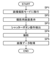
- FIG. 8 is a flowchart illustrating a process for taking an image using the smartphone 10.
- the CPU 21 of the smartphone 10 shifts to the image shooting mode when the user U inputs an instruction to set the image shooting mode, such as a camera activation instruction (step SP1).
- the CPU 21 displays the shooting screen IP (see FIG. 9) on the touch panel 24 (step SP2).
- the shooting screen IP has a zoom magnification input unit 30 which is a GUI (Graphical User Interface) for adjusting the zoom magnification, a shutter button 31, and a live view display unit 32.
- the image IM to be captured is displayed in the live view display unit 32 in the live view.
- the image IM is shown in the margin of the live view display unit 32 in order to avoid complication of the figure.
- the image IM is actually displayed in the live view display unit 32, and the image IM and the zoom magnification input unit 30 are displayed in an overlapping manner.
- the zoom magnification input unit 30 includes, for example, a magnification display unit 30a for displaying the current zoom magnification, and a magnification designation line 30b for designating the zoom magnification from the wide-angle end to the telephoto end.
- the zoom magnification is displayed based on the focal length at the wide-angle end. That is, since the zoom magnification at the wide-angle end is a reference, it is set to 1x.
- the zoom magnification at the telephoto end is 5 times as an example.
- the magnification designation line 30b is an arcuate curve. One end of the magnification designation line 30b (lower end in FIG.
- magnification display unit 30a is circular and has a size sufficient to enclose numbers indicating zoom magnification such as 1x and 5x.
- the display position of the circular magnification display unit 30a is fixed.
- the magnification designation line 30b moves along the arc-shaped locus with respect to the magnification display unit 30a by the swipe operation of the user U.
- the numbers indicating the zoom magnification such as 1x ( ⁇ 1.0) and 5x ( ⁇ 5.0) displayed at both ends of the magnification designation line 30b are movable together with the magnification designation line 30b.
- the intersection position of the magnification designation line 30b with respect to the magnification display unit 30a changes.
- the zoom magnification corresponding to the intersection position on the magnification designation line 30b is displayed.
- FIG. 9 shows a state in which 2.5 times ( ⁇ 2.5) is displayed in the magnification display unit 30a. In this way, the zoom magnification corresponding to the intersection position of the magnification designation line 30b with respect to the magnification display unit 30a is input.
- the zoom magnification input area 24a is an area including the magnification display unit 30a and the magnification designation line 30b, and is set in an arc shape along the magnification designation line 30b which is an arc-shaped curve.
- the zoom magnification input area 24a indicates a movement range in which the finger of the user U who operates the zoom magnification input unit 30 moves.
- the zoom magnification input area 24a is the first area in the technique of the present disclosure.
- the CPU 21 detects a swipe operation for moving the magnification designation line 30b within the zoom magnification input area 24a on the touch panel 24 as a zoom magnification change operation performed during shooting using the smartphone 10.
- the CPU 21 changes the zoom magnification of the photographing lens 26a or the zoom magnification of the electronic zoom.
- the image IM displayed on the live view display unit 32 is zoomed. That is, as the zoom magnification approaches the telephoto end, the subject in the image IM is enlarged while the angle of view narrows, and as the zoom magnification approaches the wide-angle end, the subject in the image IM is reduced while the angle of view widens.
- the optical axis direction Z of the photographing lens 26a provided on the back surface 11b of the housing 11 is the image photographing direction.
- the user U adjusts the shooting direction by moving the smartphone 10 and adjusting the direction of the shooting lens 26a of the smartphone 10.
- User U adjusts the shooting direction and zoom magnification, and touches the shutter button 31 when ready for shooting.
- the CPU 21 detects the operation of touching the shutter button 31 (step SP3), it controls the photographing unit 26 to perform imaging (step SP4) and acquires image data (step SP5).
- the CPU 21 saves the image data acquired by the photographing unit 26 in the storage 23, and ends the process.
- FIG. 11 is a flowchart illustrating a process for displaying an image in the image display system 1.
- the CPU 21 of the smartphone 10 shifts to the image display mode (step SP11).
- the CPU 21 acquires the resolution information of the display unit 64 of the smart glasses 50 connected to the smartphone 10 (step SP12).
- the resolution information of the display unit 64 is stored in the storage 23 together with the model information of the smart glasses 50 in the setting for wirelessly connecting the smart glasses 50 to the smartphone 10, for example.
- the CPU 21 acquires the image display mode by reading the resolution information of the display unit 64 from the storage 23 when the mode is changed to the image display mode.
- the CPU 21 executes an image acquisition process of acquiring an image from the storage 23 (step SP13).
- an image IM of a landscape showing a person shown in FIG. 9 or the like is displayed will be described.
- the resolution of the image IM taken by the smartphone 10 is 4096 dots in the horizontal direction and 3072 dots in the vertical direction.
- the CPU 21 adjusts the resolution of the image IM according to the resolution of the display unit 64 of the smart glasses 50. Adjusting the resolution of the image IM is equivalent to adjusting the image size.
- the image IM In the initial state, the image IM has a size in which the entire image IM fits in the entire screen of the display unit 64. The CPU 21 adjusts the image IM to the image size in the initial state and displays it on the smart glasses 50 (step SP14).
- the CPU 21 of the smartphone 10 displays the display screen IV on the touch panel 24, and the first operation instruction for changing the display magnification of the image IM displayed on the smart glasses 50.
- the second operation instruction for scrolling the image IM is received from the user U (step SP15).
- the display screen IV is an operation screen displayed on the touch panel 24 when displaying the image IM on the smart glasses 50.
- the image IM is not displayed on the display screen IV of the smartphone 10, and the image IM is displayed only on the smart glasses 50.
- the image IM may also be displayed on the display screen IV.
- Step SP16 is an example of an operation instruction acquisition process for acquiring a first operation instruction or a second operation instruction.
- the CPU 21 executes a display control process of changing the display magnification of the image IM and scrolling according to the acquired operation instruction, generates an image IM having a changed display mode, and displays the image IM on the smart glasses 50. Step SP18).
- step SP16 to 18 The process of changing the display magnification of the image IM and scrolling (steps SP16 to 18) is repeated until the user U inputs an instruction to end the image display.
- the user U inputs an instruction to end the image display to the smartphone 10.
- the instruction to end the image display is input by, for example, a physical button (not shown) provided on the smartphone 10 or a return button (not shown) on the touch panel 24.
- the CPU 21 receives an instruction to end the image display (determination Yes in step SP19), the CPU 21 stops the display of the image IM and ends the process.
- step SP15 the CPU 21 ends the image display in a state where no operation instruction for changing the display magnification of the image IM and scrolling is input (determination No. in step SP16).
- step SP19 the display of the image IM is stopped in the initial state, and the process is terminated.
- the zoom magnification input unit 30 is displayed on the display screen IV.
- the zoom magnification input unit 30 is displayed as an operation unit for changing the display magnification of the image IM.
- the zoom magnification input unit 30 is displayed, for example, at a position substantially the same as the shooting screen IP. This makes it possible to perform the magnification change operation for changing the display magnification by the same operation as the zoom magnification change operation performed at the time of shooting.
- the magnification input area 24b is an area that accepts the input of the magnification change operation for changing the display magnification.
- the magnification input area 24b is set in a rectangular shape wider than the zoom magnification input area 24a.
- the magnification input region 24b is a second region in the technique of the present disclosure.
- the CPU 21 detects a swipe operation for moving the magnification designation line 30b within the magnification input area 24b on the touch panel 24 as a magnification change operation for changing the display magnification. At this time, when the finger touches the position away from the magnification designation line 30b in the magnification input area 24b, the CPU 21 touches the finger at the position closest to the magnification designation line 30b from the finger contact position. Assuming that, the swipe operation with respect to the magnification designation line 30b is detected as the magnification change operation.
- FIG. 13 is a graph showing the relationship between the swipe amount (that is, the operation amount) and the magnification in the magnification change operation.
- the state in which the lower limit of the magnification shown on the magnification designation line 30b of the zoom magnification input unit 30 is superimposed on the magnification display unit 30a is set as the reference position (that is, the swipe amount is 0), and the change in the zoom magnification with respect to the swipe amount from the reference position.
- the relationship with the quantity is shown in graph R1.
- the reference position indicates the zoom magnification (1x) at the wide-angle end in the image shooting mode as described above.
- the reference position indicates that the display magnification of the image IM is 1x (1x).
- the 1x (1x) display is a state in which the entire image IM in the initial state matching the resolution of the touch panel 24 is displayed on the smart glasses 50.
- the magnification changes in proportion to the swipe amount.
- the CPU 21 determines the zoom magnification according to the swipe amount from the relationship shown in the graph R1. The larger the swipe amount, the larger the zoom magnification.
- the CPU 21 determines the display magnification according to the swipe amount from the relationship shown in the graph R1. The larger the swipe amount, the larger the display magnification. The larger the display magnification, the larger the image IM is displayed.
- the relationship between the manipulated variable and the magnification shown in the graph R1 is used for both the change in the zoom magnification in the image capturing mode and the change in the display magnification in the image display mode. Therefore, when the swipe operation of the same amount as the swipe operation in the image shooting mode is performed in the image display mode, the CPU 21 changes the display magnification of the image IM by the same amount as the change amount of the zoom magnification in the image shooting mode. become.
- the swipe operation for changing the magnification in the image display mode is an arc-shaped swipe operation, which is the same as the zoom magnification changing operation in the image shooting mode.
- the CPU 21 detects such an arc-shaped swipe operation as a magnification change operation.
- the arc-shaped swipe operation on the touch panel 24 is, for example, an arc-shaped swipe operation having a radius of 3 cm or more and 8 cm or less. This is a shape and range that can be comfortably operated when the user U holds the smartphone 10 by hand and swipes with the thumb.
- the CPU 21 acquires this swipe operation as a first operation instruction.
- the CPU 21 executes a display control process for changing the display magnification of the image IM to be displayed on the smart glasses 50 in response to the zoom magnification change operation which is the first operation instruction (see step SP17 in FIG. 11). At this time, the CPU 21 controls the amount of change in the display magnification of the image IM according to the amount of change in the magnification with respect to the operation amount of the zoom magnification change operation.
- the center position when changing the display magnification of the image IM is the center position of the image IM currently displayed on the smart glasses 50.
- the entire center position of the image IM becomes the initial position C0 of the center position when the display magnification is changed. That is, when the image IM is enlarged according to the display magnification, the image IM is enlarged centering on the initial position C0.
- the region DA indicates a region displayed on the smart glasses 50 when the image IM is enlarged around the initial position C0.
- the center position can be changed from the initial position C0.
- the center position may be specified by the user U touching an arbitrary position of the image IM.
- the image IM can be enlarged centering on the area of interest of the user U in the image IM.
- the image IM can be scrolled. For example, as shown in FIG. 15, when the area DA that is a part of the image IM is displayed, the area DA displayed in the image IM can be changed by scrolling the image IM. ..
- the user U moves the smartphone 10 in the same manner as in the case of shooting, and adjusts the direction of the shooting lens 26a of the smartphone 10 to specify the scroll direction. For example, when it is desired to scroll the image IM to the right, the direction of the photographing lens 26a of the smartphone 10 is tilted to the right from the reference direction. If the image IM is to be scrolled upward, the direction of the photographing lens 26a of the smartphone 10 is tilted upward from the reference direction.
- the reference direction in the left-right direction is set to, for example, the orientation of the photographing lens 26a of the smartphone 10 at the time of shifting to the image display mode in step SP11 shown in FIG.
- the reference direction in the vertical direction is set to, for example, a direction in which the direction of the photographing lens 26a of the smartphone 10 is the horizontal direction.
- the CPU 21 constantly monitors the posture of the smartphone 10 detected by the posture detection unit 27, and acquires a change in the posture of the smartphone 10 as a second operation instruction (see step SP16 in FIG. 11).
- the CPU 21 executes a display control process for scrolling the image IM to be displayed on the smart glasses 50 in response to the second operation instruction (step SP17).
- the CPU 21 shifts the image IM to the right from the state shown in FIG. 15, as shown in FIG. Make it scroll.
- the area DA displayed on the smart glasses 50 in the image IM is changed to the right side portion in the image IM.
- the CPU 21 scrolls the image IM upward from the state shown in FIG. 15, as shown in FIG.
- the area DA displayed on the smart glasses 50 in the image IM is changed to the upper side in the image IM.
- the CPU 21 (corresponding to a processor) of the smartphone 10 (corresponding to a photographing device and a display control device) in the present embodiment performs an image acquisition process for acquiring an image to be displayed on the smart glasses 50 (corresponding to a wearable monitor) and an image display.
- the first operation instruction input through an operation on the operation unit of the smartphone 10 separate from the smart glasses 50 in order to change the magnification, and the first operation instruction input through the magnification change operation on the smartphone 10.
- the first operation instruction acquisition process for acquiring the image and the display control process for changing the display magnification of the image according to the first operation instruction are executed.
- the user U can be made to change the display magnification of the image to be displayed on the smart glasses 50 by the magnification change operation on the smartphone 10, so that the display control device can be highly convenient.
- the display resolution of a wearable monitor such as a smart glass 50 is lower than the resolution of an image acquired by a photographing device such as a smartphone 10. Therefore, in order to confirm noise and the like in the details of the image on the wearable monitor, the operation frequency of the operation of changing the display magnification of the image and enlarging the image is high.
- the operation of changing the display magnification of an image having a high frequency of operation can be performed with the same operation feeling as the operation of changing the zoom magnification performed at the time of shooting as in this example.
- the user U can easily perform the magnification change operation. This is because changing the zoom magnification at the time of shooting and changing the display magnification at the time of displaying an image have in common that the displayed image is enlarged or reduced, and the user U is in a shooting device such as a smartphone 10. This is because it is considered that he / she is proficient in the operation of changing the zoom magnification. This makes it possible to provide a display control device having good operability and high convenience for the user.
- the magnification change operation in the shooting device is the zoom magnification changing operation at the time of shooting of the smartphone 10 which is an example of the shooting device, and the display magnification of the image on the wearable monitor is changed by the same operation as the zoom magnification changing operation.
- the magnification change operation of the present invention is an example of changing the zoom magnification, and can be applied to changing the magnification of the extender lens of the TV lens and the like.
- the magnification change operation in the photographing device may be a display magnification changing operation in which the display magnification of the image is changed when the image is displayed on the smartphone 10 which is an example of the photographing device. That is, the display magnification of the image on the wearable monitor may be changed by the same operation as the operation for changing the display magnification of the image in the photographing device.
- the CPU 21 controls the amount of change in the display magnification of the image IM according to the amount of change in the magnification with respect to the operation amount of the magnification change operation.
- Such an aspect is preferable because the display magnification of the image to be displayed on the smart glasses 50 can be changed with the same operation feeling as the magnification change operation on the smartphone 10.
- the CPU 21 further executes a second operation instruction acquisition process of acquiring a change in the posture of the smartphone 10 detected by the attitude detection unit 27 that detects the attitude of the smartphone 10 as a second operation instruction, and displays control processing.
- the image is scrolled according to the second operation instruction.
- the smartphone 10 includes a touch panel 24, and when the zoom magnification changing operation at the time of shooting of the smartphone 10 is a swipe operation within the zoom magnification input area 24a on the touch panel, the CPU 21 performs the zoom on the touch panel 24.
- a swipe operation in the magnification input area 24b including the magnification input area 24a and wider than the zoom magnification input area 24a is detected as an operation for changing the display magnification of the image.
- the CPU 21 detects an arc-shaped swipe operation having a radius R of 3 cm or more and 8 cm or less on the touch panel 24 as a display magnification change operation.
- the arcuate swipe operation having a radius R of 3 cm or more and 8 cm or less is a shape that allows the user U to comfortably perform the swipe operation when the smartphone 10 is held by the hand and the swipe operation is performed with the thumb. By adopting such an embodiment, it is possible to obtain a more convenient display control device. If the radius R of the arc-shaped swipe operation is less than 3 cm, the thumb must be bent extremely for the operation, which makes the swipe operation difficult. Further, if the radius R of the arc-shaped swipe operation exceeds 8 cm, the swipe operation becomes difficult because the thumb may not reach even if the thumb is completely extended.
- the image IM displayed on the smart glasses 50 is an image taken by the smartphone 10. That is, the same smartphone 10 can be used to take an image IM and change the display magnification when displaying the image IM. Therefore, a highly convenient display control device is realized.
- the device functioning as the display control device is changed to the smart glasses 50 instead of the smartphone 10. That is, as will be described later, the smart glasses 50 execute the image acquisition process, the first operation instruction acquisition process, and the display control process. Further, in the second embodiment, unlike the first embodiment, the image displayed on the smart glasses 50 is changed to be acquired not from the smartphone 10 but from the external server 70.
- FIG. 18 is a schematic configuration diagram of an image display system including a display control device according to a second embodiment.
- the image display system 2 includes a smartphone 10 and smart glasses 50.
- the CPU 61 of the smart glasses 50 is an example of a processor in the technique of the present disclosure.
- the memory 62 is an example of the memory in the technique of the present disclosure.
- the smart glasses 50 including the CPU 61 and the memory 62 also function as a display control device in the technique of the present disclosure.
- the CPU 61 of the smart glasses 50 acquires an image to be displayed by the smart glasses 50 from an external server 70.
- the smartphone 10 and the smart glasses 50 are directly connected wirelessly.
- the smartphone 10 and the server 70 are wirelessly connected via the network 71.
- the smart glasses 50 and the server 70 are wirelessly connected via the network 71.
- FIG. 19 is a flowchart illustrating processing at the time of image display in the image display system 2.
- the CPU 21 of the smartphone 10 shifts to the image display mode (step SP21).
- the CPU 21 transmits the image designation information indicating the designated image to the server 70 (step SP22).
- the server 70 When the server 70 receives the image designation information from the smartphone 10 (step SS21), the server 70 transmits the designated image to the smart glasses 50 (step SS22).
- the CPU 61 of the smart glasses 50 executes an image acquisition process of acquiring an image IM to be displayed on the display unit 64 by receiving an image from the server 70 (step SG21). Next, the CPU 61 adjusts the resolution of the acquired image according to the resolution of the display unit 64 of the smart glasses 50. In the initial state, the image has a size in which the entire image fits on the entire screen of the display unit 64. The CPU 61 adjusts the size of the image IM to the image size in the initial state and displays it on the display unit 64 (step SG22).
- step SP23 the CPU 21 of the smartphone 10 displays the display screen IV shown in FIG. 12 on the touch panel 24, and the user gives an instruction to change the display magnification of the image displayed on the smart glasses 50 and scroll. It is in a state of accepting from U.
- step SP24 When the first operation instruction for changing the display magnification of the image or the second operation instruction for scrolling the image IM is input (determination Yes in step SP24), the CPU 21 issues these operation instructions. It is transmitted to the server 70 (step SP25).
- the server 70 When the server 70 receives either the first operation instruction or the second operation instruction from the smartphone 10 (step SS23), the server 70 transfers this operation instruction to the smart glasses 50 (step SS24).
- the CPU 61 of the smart glasses 50 receives an operation instruction from the server 70 and executes an operation instruction acquisition process for acquiring the operation instruction as an instruction to change the display mode (step SG23). Next, the CPU 61 executes a display control process for changing or scrolling the display magnification of the image IM in response to these operation instructions, and displays the image IM whose display mode has been changed by changing the display magnification or scrolling. Is displayed (step SG24).
- the process of changing the display magnification of the image and scrolling is repeated until the user U inputs an instruction to end the image display (steps SP24 to SP26).
- the smart glasses 50 and the server 70 also repeat the process shown in FIG. 19 according to the process of the smartphone 10.
- the user U inputs an instruction to end the image display to the smartphone 10.
- the instruction to end the image display is input by, for example, a physical button (not shown) provided on the smartphone 10 or a return button (not shown) on the touch panel 24.
- the CPU 21 of the smartphone 10 transmits the display end instruction to the server 70 (step SP27), and ends the process.
- the server 70 When the server 70 receives the display end instruction from the smartphone 10 (step SS25), the server 70 transfers the display end instruction to the smart glasses 50 (step SS26).
- the CPU 61 of the smart glasses 50 When the CPU 61 of the smart glasses 50 receives the display end instruction from the server 70, the CPU 61 ends the display of the image on the display unit 64 (step SG25).
- the smart glasses 50 which is an example of the wearable monitor in the technique of the present disclosure, also functions as a display control device in the technique of the present disclosure. Further, the CPU 61 of the smart glasses 50 acquires the image IM from the external server 70 in the image acquisition process, and acquires the first operation instruction and the second operation instruction via the server 70 in the operation instruction acquisition process. do.
- images other than the images taken by the smartphone 10 can be acquired from the server 70 and displayed on the smart glasses 50.
- the smart glasses 50 when displaying the image IM on the smart glasses 50, all the data acquired by the smart glasses 50 is acquired from the server 70. Therefore, when displaying an image, the smart glasses 50 do not need to communicate with the smartphone 10, but only communicate with the server 70, so that the load of communication processing with the smartphone 10 can be reduced. can.
- the image display system according to the third embodiment has a first operation instruction and a second operation instruction in the display control process, and a display end instruction at the end of the image display, as compared with the second embodiment.
- the difference is that the CPU 61 of the smart glasses 50 directly acquires the image from the smartphone 10 without going through the server 70 (see steps SP35 and SP37 and steps SG33 and SG35). Since the hardware configuration of the smartphone 10 and the smart glasses 50 is the same as that of the second embodiment, the description thereof will be omitted.
- FIG. 20 is a flowchart illustrating processing at the time of image display in the image display system of the present embodiment.
- the CPU 21 of the smartphone 10 shifts to the image display mode (step SP31).
- the CPU 21 transmits the image designation information indicating the designated image to the server 70 (step SP32).
- the server 70 When the server 70 receives the image designation information from the smartphone 10 (step SS31), the server 70 transmits the designated image to the smart glasses 50 (step SS32).
- the CPU 61 of the smart glasses 50 When the CPU 61 of the smart glasses 50 receives an image from the server 70, it executes an image acquisition process of acquiring the image as an image to be displayed on the display unit 64 (step SG31). Next, the CPU 61 adjusts the resolution of the acquired image according to the resolution of the display unit 64 of the smart glasses 50. In the initial state, the image has a size in which the entire image fits on the entire screen of the display unit 64. The CPU 61 adjusts the image to the image size in the initial state and displays it on the display unit 64 (step SG32).
- step SP33 the CPU 21 of the smartphone 10 displays the display screen IV shown in FIG. 12 on the touch panel 24, and the user gives an instruction to change the display magnification of the image displayed on the smart glasses 50 and scroll.
- the state of accepting from U is set (step SP33).
- step SP34 When the first operation instruction for changing the display magnification of the image or the second operation instruction for scrolling the image IM is input (determination Yes in step SP34), the CPU 21 issues these operation instructions. It is transmitted to the smart glasses 50 (step SP35).
- the CPU 61 of the smart glasses 50 directly receives an operation instruction from the smartphone 10 and executes an operation instruction acquisition process for acquiring the operation instruction as an instruction to change the display mode (step SG33).
- the CPU 61 executes a display control process for changing or scrolling the display magnification of the image IM in response to these operation instructions, and the display mode is changed by changing or scrolling the display magnification, and the image is displayed on the display unit 64. (Step SP34).
- the process of changing the display magnification of the image and scrolling is repeated until the user U inputs an instruction to end the image display (steps SP34 to 36).
- the smart glasses 50 and the server 70 also repeat the process shown in FIG. 20 according to the process of the smartphone 10.
- the user U inputs an instruction to end the image display to the smartphone 10.
- the instruction to end the image display is input by, for example, a physical button (not shown) provided on the smartphone 10 or a return button (not shown) on the touch panel 24.
- the CPU 21 of the smartphone 10 transmits the display end instruction to the smart glasses 50 (step SP37), and ends the process.
- the CPU 61 of the smart glasses 50 receives the display end instruction directly from the smartphone 10, the CPU 61 ends the display of the image on the display unit 64 (step SG35).
- the smart glasses 50 which is an example of the wearable monitor in the technique of the present disclosure, also functions as a display control device in the technique of the present disclosure. Further, the CPU 61 of the smart glasses 50 acquires an image from an external server 70 in the image acquisition process, and directly acquires the first operation instruction and the second operation instruction from the smartphone 10 in the operation instruction acquisition process.
- images other than the images taken by the smartphone 10 can be acquired from the server 70 and displayed on the smart glasses 50.
- the smart glasses 50 directly acquire the first operation instruction and the second operation instruction for performing display control processing such as image display magnification change and scrolling from the smartphone 10 without going through the server 70. There is. Therefore, as compared with the case where the first operation instruction and the second operation instruction are acquired via the server 70, from the time when the user U inputs the operation instruction to the smartphone 10 until the display mode is changed. Time lag (time lag due to communication delay) can be reduced.
- the image display system according to the fourth embodiment changes the initial position C0 of the center position when changing the display magnification of the image in the display control process in the CPU 21 of the smartphone 10 as compared with the first embodiment.
- the point to do is different.
- the hardware configurations of the smartphone 10 and the smart glasses 50 are the same as those in the first embodiment, and thus the description thereof will be omitted.
- the image file F1 of the image IM handled in this embodiment has incidental information data D2 in addition to the image data D1.
- the incidental information data D2 includes information D2a of a tilt angle which is a tilt angle with respect to the horizontal direction of the smartphone 10 at the time of image capture, in addition to information such as the image capture date and time and the image capture location.
- the tilt angle ⁇ tilt is specifically an angle between the optical axis direction Z (synonymous with the photographing direction) and the horizontal direction H of the photographing lens 26a of the smartphone 10. ..
- the tilt angle ⁇ tilt is 0 ° when the optical axis direction Z faces the horizontal direction H, a positive angle when the optical axis direction Z faces the upper side of the horizontal direction H, and the optical axis direction Z is the horizontal direction.
- the negative angle is when the person is facing below H.
- FIG. 23 is a diagram for explaining the initial position C0 of the center position when changing the display magnification in the image IM.
- the coordinates of the image IM in the X direction are X
- the coordinates of the image IM in the Y direction are Y.
- the lower left coordinate is the origin (0,0)
- the upper right coordinate is the vertex (100,100).
- both the X coordinate and the Y coordinate show values obtained by normalizing the maximum value of the number of pixels of the image IM to 100.
- the coordinates of the initial position C0 of the center position when changing the display magnification of the image are set to the coordinate position of the center position of the image IM (50, 50).
- the CPU 21 of the smartphone 10 has the coordinates of the initial position C0 of the center position when changing the display magnification of the image based on the tilt angle information D2a included in the image file F1. Change the position from the default coordinate position (50, 50).
- the tilt angle ⁇ tilt when the tilt angle ⁇ tilt is 0, the coordinate position of the initial position C0 of the center position (50). , 50) is not changed from the default position.
- the tilt angle ⁇ tilt is positive, the amount of change in the center position of the Y-axis is linearly changed from 0 to 50 up to 45 °, which is larger than 0 °, and when it exceeds 45 °, the center position of the Y-axis is changed. The amount is 50.
- the amount of change in the center position of the Y-axis is linearly changed from 0 to -50 until -45 °, which is smaller than 0 °, and when it is less than -45 °, the Y-axis is changed.
- the amount of change in the center position is -50. That is, when the tilt angle is positive, the upper part in the image IM is the initial position C0 of the center position when changing the display magnification of the image IM, and when the tilt angle is negative, the lower part in the image IM is. It is the initial position C0 of the center position when changing the display magnification of the image IM.
- the coordinates of the initial position of the changed center position C0a are changed to (50,75) as shown in FIG. 23.
- the image file F1 of the image IM provides the information D2a of the tilt angle, which is the tilt angle with respect to the horizontal direction of the smartphone 10 at the time of shooting the image IM, as the incidental information data D2 in addition to the image data D1.
- the CPU 21 of the smartphone 10 changes the initial position C0 of the center position when changing the display magnification of the image IM based on the tilt angle information D2a in the display control process.
- the image IM is photographed when the tilt angle at the time of imaging is positive, that is, the optical axis direction Z of the imaging device is directed upward.
- the initial position C0 of the center position when changing the display magnification of the image IM is changed above the image IM. Therefore, when displaying the image, the user U can feel the feeling of changing the zoom at the time of shooting in a pseudo manner.
- the image display system according to the fifth embodiment is different from the first embodiment in that when displaying the image IM on the smart glasses 50, the image IM is corrected in the horizontal direction.
- the hardware configurations of the smartphone 10 and the smart glasses 50 are the same as those in the first embodiment, and thus the description thereof will be omitted.
- the image file F2 of the image IM handled in this embodiment has incidental information data D2 in addition to the image data D1.
- the incidental information data D2 is a rotation angle with respect to the horizontal direction around the optical axis direction Z (synonymous with the shooting direction) of the smartphone 10 at the time of shooting the image, in addition to information such as the shooting date and time of the image and the shooting location of the image. Includes roll angle information D2b.
- the roll angle ⁇ roll is specifically the angle between the horizontal HP and the horizontal H of the smartphone 10 at the time of shooting.
- the direction of the smartphone 10 corresponding to the lateral direction (longitudinal direction) of the image IM is defined as the lateral HP.
- the roll angle ⁇ roll is when the right end of the smartphone 10 is higher than the horizontal direction H about the optical axis direction Z in FIG. 26 when the shooting direction of the smartphone 10 is the back side of the paper surface in FIG. 26.
- the state in which the smartphone 10 is rotated counterclockwise is defined as a positive angle.
- FIG. 26 when the right end of the smartphone 10 is lower than the horizontal direction H about the optical axis direction Z (FIG. 26 shows this state), that is, the smartphone 10 is rotating clockwise. Let the state be a negative angle.
- FIG. 26 shows a state in which a horizontally long image is taken with the smartphone 10.
- the longitudinal direction of the housing 11 of the smartphone 10 is the lateral HP of the smartphone 10.
- the roll angle ⁇ roll of the smartphone 10 at the time of taking an image is shown in a negative state.
- the horizontal HI of the subject in the image IM is in a state of rotating counterclockwise about the center CI of the image IM.
- the CPU 21 of the smartphone 10 corrects the image IM in the horizontal direction when displaying the image on the smart glasses 50.
- the entire image IM may be rotated by the same angle as the roll angle ⁇ roll with the center CI of the image IM as the axis.
- the direction in which the image IM is rotated counterclockwise is set as a positive angle.
- the direction in which the image IM is rotated clockwise is set to a negative angle.
- the horizontal HI of the subject in the image IM is counterclockwise with the center CI of the image IM as the axis. It will be in a state of being rotated by 20 °. Therefore, as shown in FIG. 28, the horizontal HI of the subject in the image IM is imaged by rotating the entire image IM by ⁇ 20 °, which is the same as the angle of the roll angle ⁇ roll, about the center CI of the image IM. It can be matched with the left-right direction of IM.
- the horizontal direction of the subject can be matched with the left-right direction of the image IM, so that the user U does not feel a sense of discomfort.
- the image display system according to the sixth embodiment is used for shooting when the shooting device for shooting is different from the shooting device for inputting operation instructions such as a magnification change operation and scrolling of an image. It is a configuration for matching the change amount of the magnification with respect to the operation amount of the magnification change operation and the change amount of the magnification with respect to the operation amount when changing the display magnification of the image.
- the content of the display control process in the CPU 21 of the smartphone 10 is different in this embodiment as compared with the first embodiment.
- the hardware configurations of the smartphone 10 and the smart glasses 50 are the same as those in the first embodiment, and thus the description thereof will be omitted.
- the image file F3 of the image handled in this embodiment has incidental information data D2 in addition to the image data D1.
- incidental information data D2 in addition to information such as the shooting date and time of the image and the shooting location of the image, the magnification change regarding the amount of change in the magnification with respect to the operation amount of the magnification change operation at the time of shooting in the shooting device that shot the image.
- operation-related information D2c in addition to information such as the shooting date and time of the image and the shooting location of the image.
- the image stored in the storage 23 of the smartphone 10 of the image display system is not necessarily the image taken by the smartphone 10. If the maximum zoom magnification of the smartphone that took the image and the maximum zoom magnification of the smartphone 10 are different, the operation feeling when changing the zoom magnification will be different between the smartphone that took the image and the smartphone 10. Become.
- the CPU 21 of the smartphone 10 obtains information on the maximum zoom magnification of the smartphone that captured the image as the magnification change operation related information D2c from the incidental information data D2 of the image file F3 of the image to be displayed. get.
- FIG. 30 is a graph showing the relationship between the swipe amount (that is, the operation amount) and the magnification in the zoom magnification change operation.
- the maximum zoom magnification of the smartphone 10 is 5 times and the maximum zoom magnification of the smartphone that has taken an image is 10 times will be described.
- the state in which the lower limit of the magnification designation line 30b of the zoom magnification input unit 30 on the smartphone 10 is superimposed on the magnification display unit 30a is set as the reference position (that is, the swipe amount is 0), and the relationship between the amount of change in the magnification with respect to the swipe amount from the reference position. Is shown in graph R1.
- the state in which the lower limit of the magnification designation line of the zoom magnification input unit of the smartphone on which the image was taken is superimposed on the magnification display unit is set as the reference position (that is, the swipe amount is 0), and the magnification with respect to the swipe amount from the reference position is set.
- the relationship between the amounts of change is shown in Graph R2.
- the maximum zoom magnification of the smartphone that took the image is 10 times, and the maximum zoom magnification of the smartphone 10 is 5 times. Therefore, even if the same amount of operation is performed in the zoom magnification change operation, the operation amount is the same. The amount of change in zoom magnification does not match.
- the CPU 21 of the smartphone 10 determines the amount of change in the zoom magnification with respect to the operation amount of the zoom magnification changing operation in the smartphone that captured the image and the smartphone 10 based on the information of the maximum zoom magnification of the smartphone that captured the image. Performs processing to match the amount of change in zoom magnification with respect to the operation of changing the zoom magnification in.
- the display magnification at one end of the magnification designation line 30b is set to 1 and the display magnification at the other end of the magnification designation line 30b is set to the display magnification of the smartphone that has taken an image. It is set to 10 times, which is the same as the maximum zoom magnification, and the display magnification of the intermediate portion is set from 1 to 10 times according to the distance from one end.
- the display magnification at one end of the magnification designation line 30b is set to 1x, and the display magnification at the other end of the magnification designation line 30b is set to 10x.
- the display magnification of the intermediate portion is set from 1 to 10 times according to the distance from one end.
- the maximum zoom magnification of the smartphone that captured the image and the maximum zoom magnification of the smartphone 10 are different, the image was captured to give an operation feeling at the time of the zoom magnification changing operation. It can be the same for the smartphone and the smartphone 10.
- the operation feeling at the time of the zoom magnification change operation on the smartphone 10 can be made closer to the operation feeling of the smartphone on which the image was taken.
- the image display system according to the seventh embodiment is used for shooting, in particular, when the shooting device for shooting is different from the shooting device for inputting operation instructions such as image magnification change operation and scrolling. It is a configuration for matching the change amount of the magnification with respect to the operation amount of the magnification change operation and the change amount of the magnification with respect to the operation amount when changing the display magnification of the image.
- the interface of the zoom magnification changing operation in the smartphone 10 is different in this embodiment as compared with the sixth embodiment. Further, the content of the display control process in the CPU 21 of the smartphone 10 is different.
- the hardware configuration of the smartphone 10 main body and the smart glasses 50 is the same as that of the first embodiment, and thus the description thereof will be omitted.
- the smartphone 10 is combined with the smartphone cover 15.
- the smartphone cover 15 includes a cover portion 16 and a ring-type controller 18.
- the cover portion 16 engages with the smartphone 10.
- the cover portion 16 is formed with an opening 17 for exposing the photographing lens 26a of the smartphone 10 when the smartphone 10 is engaged.
- a ring type controller 18 is rotatably attached to the back surface 16b of the cover portion 16 with respect to the cover portion 16.
- the ring-type controller 18 is rotatable with respect to the cover portion 16 like the zoom ring of a general digital camera, and functions as an interface for zoom magnification change operation and display magnification change operation in the smartphone 10.
- the ring-type controller 18 includes a detection unit (not shown) that detects the rotation direction and rotation angle of the ring-type controller 18 inside.
- a signal indicating the rotation direction and rotation angle of the ring-type controller 18 detected by the detection unit is transmitted to the smartphone 10 by a communication unit (not shown).
- a standard such as Bluetooth (registered trademark) is used.
- the image file F4 of the image handled in this embodiment has incidental information data D2 in addition to the image data D1.
- incidental information data D2 in addition to information such as the shooting date and time of the image and the shooting location of the image, the magnification change regarding the amount of change in the magnification with respect to the operation amount of the magnification change operation at the time of shooting in the shooting device that shot the image.
- operation-related information D2d in addition to information such as the shooting date and time of the image and the shooting location of the image.
- the magnification change operation related information D2d information on the amount of change in magnification with respect to the amount of change in the rotation angle of the zoom ring of the digital camera in which the image was taken and information on the maximum zoom magnification of the digital camera are provided. The case where it is recorded will be described.
- the image stored in the storage 23 of the smartphone 10 of the image display system is not necessarily the image taken by the smartphone 10.
- the photographing device that captures the image is a digital camera, the operation feeling at the time of the zoom magnification change operation is different between the digital camera and the smartphone 10.
- the zoom magnification is changed by rotating the zoom ring, but in the smartphone 10, the zoom magnification is changed by swiping to the touch panel 24.
- the smartphone cover 15 is a cover for allowing the smartphone 10 to perform the zoom magnification changing operation with the same operation feeling as that of a digital camera.
- the ring-type controller 18 of the smartphone cover 15 functions as an interface for changing the zoom magnification in the smartphone 10.
- the CPU 21 of the smartphone 10 determines the magnification with respect to the amount of change in the rotation angle of the zoom ring of the digital camera that captured the image as the magnification change operation related information D2d from the incidental information data D2 of the image file F4 of the image to be displayed. Acquires information on the amount of change and information on the maximum zoom magnification of the digital camera.
- FIG. 35 is a graph showing the relationship between the rotation amount (that is, the operation amount) of the zoom ring or the ring type controller 18 and the magnification in the zoom magnification change operation.
- the rotation amount that is, the operation amount
- FIG. 35 is a graph showing the relationship between the rotation amount (that is, the operation amount) of the zoom ring or the ring type controller 18 and the magnification in the zoom magnification change operation.
- the zoom magnification is increased by 1 time and the maximum zoom magnification is 5 times each time the ring type controller 18 is rotated 90 ° clockwise
- the digital camera that captured the image a case where the zoom magnification is increased by 1 time and the maximum zoom magnification is 10 times each time the zoom ring is rotated clockwise by 40 ° will be described.
- Graph R10 shows the relationship between the amount of change in the zoom magnification and the amount of rotation (that is, the amount of operation) from the reference position (that is, the amount of rotation 0) of the ring-type controller 18 in the smartphone 10. Further, the lower limit position of the magnification of the zoom ring in the digital camera in which the image was taken is set as the reference position (that is, the rotation amount is 0), and the relationship of the change amount of the zoom magnification with the rotation amount (that is, the operation amount) from the reference position is set. It is shown in the graph R20.
- the ring-type controller 18 has no end of rotation and can be freely rotated in the same direction as many times as necessary. Therefore, the reference position of the ring-type controller 18 may be, for example, the position of the ring-type controller 18 at the time when the image in the initial display state is displayed on the display unit 64.
- the amount of change in magnification with respect to the amount of change in the rotation angle of the zoom ring of the digital camera that captured the image is different from that of the ring-type controller 18 mounted on the smartphone 10. Further, the maximum zoom magnification of the digital camera that captured the image is also different from that of the smartphone 10. Therefore, even if the same operation amount is performed in the zoom magnification change operation, the change amount of the zoom magnification does not match.
- the CPU 21 of the smartphone 10 takes an image based on the information on the amount of change in magnification with respect to the amount of change in the rotation angle of the zoom ring of the digital camera that took the image and the information on the maximum zoom magnification of the digital camera.
- a process is performed in which the amount of change in the zoom magnification with respect to the operation amount of the zoom magnification change operation in the digital camera is matched with the amount of change in the zoom magnification with respect to the operation of the zoom magnification change operation in the smartphone 10.
- the operation input of the ring-type controller 18 mounted on the smartphone 10 is set to increase the zoom magnification by 1 time every time it is rotated by 40 ° clockwise. Also, set the maximum zoom magnification to 10x.
- the image display system according to the eighth embodiment has a scroll amount when scrolling an image in response to a second operation instruction in the display control process in the CPU 21 of the smartphone 10, as compared with the first embodiment.
- the points to be corrected are different.
- the hardware configurations of the smartphone 10 and the smart glasses 50 are the same as those in the first embodiment, and thus the description thereof will be omitted.
- the image file F5 of the image IM handled in this embodiment has incidental information data D2 in addition to the image data D1.
- the incidental information data D2 includes information such as the shooting date and time of the image, the shooting location of the image, and the angle of view information D2e regarding the angle of view of the smartphone 10 at the time of shooting the image.
- the angle of view information D2e may be information as long as the angle of view of the smartphone 10 at the time of shooting can be specified, and may be information on the angle of view itself or information on a zoom magnification corresponding to the angle of view. In addition, when acquiring the information of the zoom magnification, the information of the angle of view corresponding to the zoom magnification may be acquired separately.
- the angle of view information D2e is the angle of view of the shooting area.
- the angle of view ⁇ avw at the wide-angle end (that is, the zoom magnification is 1x) of the smartphone 10 at the time of taking an image is compared with the angle of view ⁇ avt at the telephoto end (that is, the zoom magnification is 5x). Is 5 times larger. Further, as the angle of view at the time of shooting an image becomes larger, the tilt angle of the smartphone 10 required to change the direction of the shooting lens 26a from one end to multiple ends of the shooting range becomes larger. As in the above example, when the angle of view is increased by 5 times, the tilt angle of the smartphone 10 required to change the direction of the photographing lens 26a from one end to multiple ends of the photographing range is increased by 5 times.
- the CPU 21 of the smartphone 10 executes a display control process for scrolling an image to be displayed on the display unit 64 of the smart glasses 50 in response to a second operation instruction
- the CPU 21 of the image is based on the angle of view information D2e at the time of shooting. Correct the scroll amount.
- the scroll amount of the image is corrected so as to match the tilt angle of the smartphone 10 required for the change.
- the setting information at the time of shooting of the smartphone 10 may be supplementarily displayed in the image IX displayed in a part of the field of view of the right eye.
- the live view of the smartphone 10 may be displayed, or the live view of the smartphone 10 and the setting information may be superimposed and displayed. ..
- the smart glasses 50 are not limited to displaying an image in a part of the field of view of the right eye, but display an image in a part of the field of view of the left eye, a part of the field of view of both eyes, or the entire field of view of both eyes. May be good.
- the wearable monitor in the technique of the present disclosure is not limited to smart glasses, but may be another display device such as an HMD.
- the photographing device in the technique of the present disclosure is not limited to the smartphone, and may be a digital camera having the same function as the smartphone 10.
- processors other than the CPU may execute the processing in which the CPU 21 and the CPU 61 read the software (program) and execute the software (program) in each of the above embodiments.
- the processor includes a PLD (Programmable Logic Device) whose circuit configuration can be changed after manufacturing an FPGA (Field-Programmable Gate Array), and an ASIC (Application Specific Integrated Circuit) for specifying an ASIC.
- PLD Programmable Logic Device
- FPGA Field-Programmable Gate Array
- ASIC Application Specific Integrated Circuit
- An example is a dedicated electric circuit or the like, which is a processor having a circuit configuration designed exclusively for it.
- each process may be executed by one of these various processors, or a combination of two or more processors of the same type or different types (for example, a plurality of FPGAs, and a combination of a CPU and an FPGA, etc.). ) May be executed.
- the hardware-like structure of these various processors is, more specifically, an electric circuit in which circuit elements such as semiconductor elements are combined.
- the mode in which the display control program is stored (installed) in the storage 23 or the storage 63 in advance has been described, but the present invention is not limited to this.
- the program is provided in a form recorded on a recording medium such as a CD-ROM (Compact Disk Read Only Memory), a DVD-ROM (Digital Versaille Disc Read Only Memory), and a USB (Universal Serial Bus) memory. Further, the program may be downloaded from an external device via a network.
- the ROM is a broad concept including a flash memory which is a rewritable ROM, an EPROM (Erasable Programmable Read Only Memory), an EEPROM (Electrically Erasable Project Only Memory), and the like.
- the CPU is integrally provided inside the wearable device or integrally provided with the smartphone.
- the CPU may be provided on a network connected to a wearable device or a smartphone, an operation unit connected to the network, or a cloud computing unit connected to the network.
- the network is managed by the cloud system, and the CPU connected on the network uses cloud computing technology to network. It is desirable to virtually operate as a wearable device or a CPU built into a smartphone while passing through the network.
- the wearable monitor which is an example of a wearable device provided with a monitor, does not have a camera, but even if it has a camera and can shoot by itself without combining with a shooting device. I do not care. In this case, it is preferable that the wearable monitor can also shoot with the camera on the shooting device side when combined with the shooting device.
Landscapes
- Engineering & Computer Science (AREA)
- Physics & Mathematics (AREA)
- General Engineering & Computer Science (AREA)
- Theoretical Computer Science (AREA)
- General Physics & Mathematics (AREA)
- Human Computer Interaction (AREA)
- Optics & Photonics (AREA)
- User Interface Of Digital Computer (AREA)
- Controls And Circuits For Display Device (AREA)
Priority Applications (5)
| Application Number | Priority Date | Filing Date | Title |
|---|---|---|---|
| CN202180073026.7A CN116457745A (zh) | 2020-10-27 | 2021-10-04 | 显示控制装置、显示控制方法及显示控制程序 |
| JP2022558947A JP7686663B2 (ja) | 2020-10-27 | 2021-10-04 | 表示制御装置、表示制御方法、および表示制御プログラム |
| US18/306,422 US12007563B2 (en) | 2020-10-27 | 2023-04-25 | Display control device, display control method, and display control program |
| US18/653,781 US12332440B2 (en) | 2020-10-27 | 2024-05-02 | Display control device, display control method, and display control program |
| US19/217,890 US20250284126A1 (en) | 2020-10-27 | 2025-05-23 | Display control device, display control method, and display control program |
Applications Claiming Priority (2)
| Application Number | Priority Date | Filing Date | Title |
|---|---|---|---|
| JP2020179750 | 2020-10-27 | ||
| JP2020-179750 | 2020-10-27 |
Related Child Applications (1)
| Application Number | Title | Priority Date | Filing Date |
|---|---|---|---|
| US18/306,422 Continuation US12007563B2 (en) | 2020-10-27 | 2023-04-25 | Display control device, display control method, and display control program |
Publications (1)
| Publication Number | Publication Date |
|---|---|
| WO2022091700A1 true WO2022091700A1 (ja) | 2022-05-05 |
Family
ID=81382408
Family Applications (1)
| Application Number | Title | Priority Date | Filing Date |
|---|---|---|---|
| PCT/JP2021/036534 Ceased WO2022091700A1 (ja) | 2020-10-27 | 2021-10-04 | 表示制御装置、表示制御方法、および表示制御プログラム |
Country Status (4)
| Country | Link |
|---|---|
| US (3) | US12007563B2 (https=) |
| JP (1) | JP7686663B2 (https=) |
| CN (1) | CN116457745A (https=) |
| WO (1) | WO2022091700A1 (https=) |
Families Citing this family (2)
| Publication number | Priority date | Publication date | Assignee | Title |
|---|---|---|---|---|
| US12277359B2 (en) * | 2021-07-01 | 2025-04-15 | Maxell, Ltd. | Information processing apparatus, photographed image transfer and display system, and photographed image transfer and display method |
| CN119211483A (zh) * | 2024-09-04 | 2024-12-27 | 姚勇 | 影像系统和影像处理方法 |
Citations (4)
| Publication number | Priority date | Publication date | Assignee | Title |
|---|---|---|---|---|
| JP2013134532A (ja) * | 2011-12-26 | 2013-07-08 | Sony Corp | ヘッドマウントディスプレイ及び情報表示装置 |
| JP2019105678A (ja) * | 2017-12-11 | 2019-06-27 | 京セラドキュメントソリューションズ株式会社 | 表示装置、及び画像表示方法 |
| JP2020042064A (ja) * | 2018-09-06 | 2020-03-19 | キヤノン株式会社 | 表示制御装置、撮像装置、制御方法、プログラム、及び、記憶媒体 |
| JP2020129261A (ja) * | 2019-02-08 | 2020-08-27 | キヤノン株式会社 | 電子機器、電子機器の制御方法、プログラム、及び、記憶媒体 |
Family Cites Families (10)
| Publication number | Priority date | Publication date | Assignee | Title |
|---|---|---|---|---|
| US11003351B2 (en) * | 2012-12-26 | 2021-05-11 | Gree, Inc. | Display processing method and information device |
| EP2998849A4 (en) | 2013-05-15 | 2017-01-25 | Sony Corporation | Display control device, display control method, and recording medium |
| US20160088060A1 (en) * | 2014-09-24 | 2016-03-24 | Microsoft Technology Licensing, Llc | Gesture navigation for secondary user interface |
| US10013808B2 (en) * | 2015-02-03 | 2018-07-03 | Globus Medical, Inc. | Surgeon head-mounted display apparatuses |
| KR102660859B1 (ko) * | 2016-12-27 | 2024-04-26 | 삼성전자주식회사 | 전자 장치, 웨어러블 장치 및 전자 장치의 표시 객체 제어 방법 |
| US10877262B1 (en) * | 2017-06-21 | 2020-12-29 | Itzhak Luxembourg | Magnification glasses with multiple cameras |
| US10591730B2 (en) * | 2017-08-25 | 2020-03-17 | II Jonathan M. Rodriguez | Wristwatch based interface for augmented reality eyewear |
| US11409091B2 (en) * | 2019-12-31 | 2022-08-09 | Carl Zeiss Meditec Ag | Method of operating a surgical microscope and surgical microscope |
| US11297285B2 (en) * | 2020-03-27 | 2022-04-05 | Sean Solon Pierce | Dental and medical loupe system for lighting control, streaming, and augmented reality assisted procedures |
| US20220039873A1 (en) * | 2020-08-06 | 2022-02-10 | Melvyn Harris | Ultrasound guidance system and method |
-
2021
- 2021-10-04 JP JP2022558947A patent/JP7686663B2/ja active Active
- 2021-10-04 WO PCT/JP2021/036534 patent/WO2022091700A1/ja not_active Ceased
- 2021-10-04 CN CN202180073026.7A patent/CN116457745A/zh active Pending
-
2023
- 2023-04-25 US US18/306,422 patent/US12007563B2/en active Active
-
2024
- 2024-05-02 US US18/653,781 patent/US12332440B2/en active Active
-
2025
- 2025-05-23 US US19/217,890 patent/US20250284126A1/en active Pending
Patent Citations (4)
| Publication number | Priority date | Publication date | Assignee | Title |
|---|---|---|---|---|
| JP2013134532A (ja) * | 2011-12-26 | 2013-07-08 | Sony Corp | ヘッドマウントディスプレイ及び情報表示装置 |
| JP2019105678A (ja) * | 2017-12-11 | 2019-06-27 | 京セラドキュメントソリューションズ株式会社 | 表示装置、及び画像表示方法 |
| JP2020042064A (ja) * | 2018-09-06 | 2020-03-19 | キヤノン株式会社 | 表示制御装置、撮像装置、制御方法、プログラム、及び、記憶媒体 |
| JP2020129261A (ja) * | 2019-02-08 | 2020-08-27 | キヤノン株式会社 | 電子機器、電子機器の制御方法、プログラム、及び、記憶媒体 |
Also Published As
| Publication number | Publication date |
|---|---|
| US20240280815A1 (en) | 2024-08-22 |
| JPWO2022091700A1 (https=) | 2022-05-05 |
| US12007563B2 (en) | 2024-06-11 |
| US20230258935A1 (en) | 2023-08-17 |
| US20250284126A1 (en) | 2025-09-11 |
| CN116457745A (zh) | 2023-07-18 |
| US12332440B2 (en) | 2025-06-17 |
| JP7686663B2 (ja) | 2025-06-02 |
Similar Documents
| Publication | Publication Date | Title |
|---|---|---|
| JP7713597B2 (ja) | メディアをキャプチャ及び表示するためのデバイス、方法、及びグラフィカルユーザインタフェース | |
| CN110456967B (zh) | 信息处理方法、信息处理设备以及程序 | |
| CN107315512B (zh) | 图像处理设备、图像处理方法和程序 | |
| US9886086B2 (en) | Gesture-based reorientation and navigation of a virtual reality (VR) interface | |
| CN102197918A (zh) | 化妆镜调整系统、方法及具有该调整系统的化妆镜 | |
| CN106104632A (zh) | 信息处理方法、信息处理设备和程序 | |
| CN110546601A (zh) | 信息处理装置、信息处理方法和程序 | |
| JP7665400B2 (ja) | 電子機器、その制御方法、プログラムおよび記憶媒体 | |
| JP7154789B2 (ja) | 表示制御装置、その制御方法、プログラム及び記憶媒体 | |
| US20250284126A1 (en) | Display control device, display control method, and display control program | |
| JP7527778B2 (ja) | 電子機器、電子機器の制御方法、プログラム、記憶媒体 | |
| US10924680B2 (en) | Image capture control apparatus and method of controlling the same | |
| US12212732B2 (en) | Image processing apparatus, image processing method, and storage medium | |
| US20200073621A1 (en) | Systems, Devices, Components and Associated Computer Executable Code For Providing Remote Viewing of a Display Associated with a Computational Device | |
| JPWO2022091700A5 (https=) | ||
| JP7775072B2 (ja) | レンズシステム | |
| US12389114B2 (en) | Image pickup device capable of performing image pickup in a plurality of image-pickup modes in parallel and control method thereof | |
| CN117395367A (zh) | 信息处理设备、信息处理方法和计算机可读介质 | |
| US20250315194A1 (en) | Image processing apparatus with vr image display control function, image processing system, non-transitory computer-readable medium, and control method of image processing apparatus | |
| JP7157444B2 (ja) | カメラ付き情報端末及プログラム | |
| JP2025099100A (ja) | 電子機器、電子機器の制御方法、プログラムおよび記憶媒体 | |
| JP2024072581A (ja) | 撮像装置、撮像装置の制御方法、プログラム | |
| JP2026018101A (ja) | 表示装置、表示装置の制御方法、およびプログラム | |
| JP2023176161A (ja) | 情報処理装置、撮像装置、情報処理方法、プログラム |
Legal Events
| Date | Code | Title | Description |
|---|---|---|---|
| 121 | Ep: the epo has been informed by wipo that ep was designated in this application |
Ref document number: 21885819 Country of ref document: EP Kind code of ref document: A1 |
|
| ENP | Entry into the national phase |
Ref document number: 2022558947 Country of ref document: JP Kind code of ref document: A |
|
| WWE | Wipo information: entry into national phase |
Ref document number: 202180073026.7 Country of ref document: CN |
|
| NENP | Non-entry into the national phase |
Ref country code: DE |
|
| 122 | Ep: pct application non-entry in european phase |
Ref document number: 21885819 Country of ref document: EP Kind code of ref document: A1 |