WO2022091525A1 - Input device - Google Patents
Input device Download PDFInfo
- Publication number
- WO2022091525A1 WO2022091525A1 PCT/JP2021/029782 JP2021029782W WO2022091525A1 WO 2022091525 A1 WO2022091525 A1 WO 2022091525A1 JP 2021029782 W JP2021029782 W JP 2021029782W WO 2022091525 A1 WO2022091525 A1 WO 2022091525A1
- Authority
- WO
- WIPO (PCT)
- Prior art keywords
- unit
- position detection
- input device
- operation unit
- detection sensor
- Prior art date
Links
- 238000001514 detection method Methods 0.000 claims abstract description 303
- 230000003993 interaction Effects 0.000 claims abstract description 7
- 239000003990 capacitor Substances 0.000 claims description 29
- 238000003860 storage Methods 0.000 claims description 24
- 230000008859 change Effects 0.000 claims description 16
- 230000005674 electromagnetic induction Effects 0.000 claims description 12
- 239000004020 conductor Substances 0.000 claims description 8
- 238000006073 displacement reaction Methods 0.000 claims description 8
- 230000004044 response Effects 0.000 claims description 2
- 230000010365 information processing Effects 0.000 description 30
- 239000000758 substrate Substances 0.000 description 27
- 238000012545 processing Methods 0.000 description 25
- 230000008878 coupling Effects 0.000 description 22
- 238000010168 coupling process Methods 0.000 description 22
- 238000005859 coupling reaction Methods 0.000 description 22
- 210000003811 finger Anatomy 0.000 description 22
- 238000003780 insertion Methods 0.000 description 20
- 230000037431 insertion Effects 0.000 description 20
- 229910000859 α-Fe Inorganic materials 0.000 description 20
- 238000000034 method Methods 0.000 description 16
- 238000003825 pressing Methods 0.000 description 16
- 238000004891 communication Methods 0.000 description 11
- 230000001681 protective effect Effects 0.000 description 9
- 238000010586 diagram Methods 0.000 description 8
- 230000005540 biological transmission Effects 0.000 description 5
- 230000002093 peripheral effect Effects 0.000 description 5
- 238000004804 winding Methods 0.000 description 5
- 230000007246 mechanism Effects 0.000 description 4
- 230000008569 process Effects 0.000 description 4
- 238000013461 design Methods 0.000 description 3
- 230000000694 effects Effects 0.000 description 2
- 230000007274 generation of a signal involved in cell-cell signaling Effects 0.000 description 2
- 238000005304 joining Methods 0.000 description 2
- 238000004519 manufacturing process Methods 0.000 description 2
- 210000003813 thumb Anatomy 0.000 description 2
- 102100033657 All-trans retinoic acid-induced differentiation factor Human genes 0.000 description 1
- 101100270014 Arabidopsis thaliana APR2 gene Proteins 0.000 description 1
- 101000733623 Homo sapiens All-trans retinoic acid-induced differentiation factor Proteins 0.000 description 1
- 101100066027 Homo sapiens FAM215A gene Proteins 0.000 description 1
- 101001057135 Homo sapiens Melanoma-associated antigen H1 Proteins 0.000 description 1
- 102100027256 Melanoma-associated antigen H1 Human genes 0.000 description 1
- 102100026728 Uncharacterized protein FAM215A Human genes 0.000 description 1
- 230000003213 activating effect Effects 0.000 description 1
- 239000000853 adhesive Substances 0.000 description 1
- 230000001070 adhesive effect Effects 0.000 description 1
- 230000008901 benefit Effects 0.000 description 1
- 230000005489 elastic deformation Effects 0.000 description 1
- 239000013013 elastic material Substances 0.000 description 1
- 210000004936 left thumb Anatomy 0.000 description 1
- 239000000696 magnetic material Substances 0.000 description 1
- 238000012986 modification Methods 0.000 description 1
- 230000004048 modification Effects 0.000 description 1
- 230000002265 prevention Effects 0.000 description 1
- 239000011347 resin Substances 0.000 description 1
- 229920005989 resin Polymers 0.000 description 1
- 210000004935 right thumb Anatomy 0.000 description 1
Images


Classifications
-
- G—PHYSICS
- G06—COMPUTING; CALCULATING OR COUNTING
- G06F—ELECTRIC DIGITAL DATA PROCESSING
- G06F3/00—Input arrangements for transferring data to be processed into a form capable of being handled by the computer; Output arrangements for transferring data from processing unit to output unit, e.g. interface arrangements
- G06F3/01—Input arrangements or combined input and output arrangements for interaction between user and computer
- G06F3/03—Arrangements for converting the position or the displacement of a member into a coded form
- G06F3/033—Pointing devices displaced or positioned by the user, e.g. mice, trackballs, pens or joysticks; Accessories therefor
- G06F3/039—Accessories therefor, e.g. mouse pads
- G06F3/0393—Accessories for touch pads or touch screens, e.g. mechanical guides added to touch screens for drawing straight lines, hard keys overlaying touch screens or touch pads
-
- G—PHYSICS
- G06—COMPUTING; CALCULATING OR COUNTING
- G06F—ELECTRIC DIGITAL DATA PROCESSING
- G06F3/00—Input arrangements for transferring data to be processed into a form capable of being handled by the computer; Output arrangements for transferring data from processing unit to output unit, e.g. interface arrangements
- G06F3/01—Input arrangements or combined input and output arrangements for interaction between user and computer
- G06F3/03—Arrangements for converting the position or the displacement of a member into a coded form
- G06F3/033—Pointing devices displaced or positioned by the user, e.g. mice, trackballs, pens or joysticks; Accessories therefor
- G06F3/038—Control and interface arrangements therefor, e.g. drivers or device-embedded control circuitry
-
- G—PHYSICS
- G06—COMPUTING; CALCULATING OR COUNTING
- G06F—ELECTRIC DIGITAL DATA PROCESSING
- G06F3/00—Input arrangements for transferring data to be processed into a form capable of being handled by the computer; Output arrangements for transferring data from processing unit to output unit, e.g. interface arrangements
- G06F3/01—Input arrangements or combined input and output arrangements for interaction between user and computer
- G06F3/02—Input arrangements using manually operated switches, e.g. using keyboards or dials
- G06F3/0202—Constructional details or processes of manufacture of the input device
- G06F3/0205—Lever arrangements for operating keyboard cursor control keys in a joystick-like manner
-
- G—PHYSICS
- G06—COMPUTING; CALCULATING OR COUNTING
- G06F—ELECTRIC DIGITAL DATA PROCESSING
- G06F3/00—Input arrangements for transferring data to be processed into a form capable of being handled by the computer; Output arrangements for transferring data from processing unit to output unit, e.g. interface arrangements
- G06F3/01—Input arrangements or combined input and output arrangements for interaction between user and computer
- G06F3/03—Arrangements for converting the position or the displacement of a member into a coded form
- G06F3/033—Pointing devices displaced or positioned by the user, e.g. mice, trackballs, pens or joysticks; Accessories therefor
- G06F3/0338—Pointing devices displaced or positioned by the user, e.g. mice, trackballs, pens or joysticks; Accessories therefor with detection of limited linear or angular displacement of an operating part of the device from a neutral position, e.g. isotonic or isometric joysticks
-
- G—PHYSICS
- G06—COMPUTING; CALCULATING OR COUNTING
- G06F—ELECTRIC DIGITAL DATA PROCESSING
- G06F3/00—Input arrangements for transferring data to be processed into a form capable of being handled by the computer; Output arrangements for transferring data from processing unit to output unit, e.g. interface arrangements
- G06F3/01—Input arrangements or combined input and output arrangements for interaction between user and computer
- G06F3/03—Arrangements for converting the position or the displacement of a member into a coded form
- G06F3/033—Pointing devices displaced or positioned by the user, e.g. mice, trackballs, pens or joysticks; Accessories therefor
- G06F3/0362—Pointing devices displaced or positioned by the user, e.g. mice, trackballs, pens or joysticks; Accessories therefor with detection of 1D translations or rotations of an operating part of the device, e.g. scroll wheels, sliders, knobs, rollers or belts
-
- G—PHYSICS
- G06—COMPUTING; CALCULATING OR COUNTING
- G06F—ELECTRIC DIGITAL DATA PROCESSING
- G06F3/00—Input arrangements for transferring data to be processed into a form capable of being handled by the computer; Output arrangements for transferring data from processing unit to output unit, e.g. interface arrangements
- G06F3/01—Input arrangements or combined input and output arrangements for interaction between user and computer
- G06F3/03—Arrangements for converting the position or the displacement of a member into a coded form
- G06F3/041—Digitisers, e.g. for touch screens or touch pads, characterised by the transducing means
-
- H—ELECTRICITY
- H01—ELECTRIC ELEMENTS
- H01H—ELECTRIC SWITCHES; RELAYS; SELECTORS; EMERGENCY PROTECTIVE DEVICES
- H01H13/00—Switches having rectilinearly-movable operating part or parts adapted for pushing or pulling in one direction only, e.g. push-button switch
- H01H13/02—Details
- H01H13/12—Movable parts; Contacts mounted thereon
- H01H13/14—Operating parts, e.g. push-button
-
- H—ELECTRICITY
- H01—ELECTRIC ELEMENTS
- H01H—ELECTRIC SWITCHES; RELAYS; SELECTORS; EMERGENCY PROTECTIVE DEVICES
- H01H25/00—Switches with compound movement of handle or other operating part
- H01H25/04—Operating part movable angularly in more than one plane, e.g. joystick
-
- H—ELECTRICITY
- H01—ELECTRIC ELEMENTS
- H01H—ELECTRIC SWITCHES; RELAYS; SELECTORS; EMERGENCY PROTECTIVE DEVICES
- H01H25/00—Switches with compound movement of handle or other operating part
- H01H25/04—Operating part movable angularly in more than one plane, e.g. joystick
- H01H25/041—Operating part movable angularly in more than one plane, e.g. joystick having a generally flat operating member depressible at different locations to operate different controls
Landscapes
- Engineering & Computer Science (AREA)
- General Engineering & Computer Science (AREA)
- Theoretical Computer Science (AREA)
- Human Computer Interaction (AREA)
- Physics & Mathematics (AREA)
- General Physics & Mathematics (AREA)
- Position Input By Displaying (AREA)
Abstract
Provided is an input device which enables, when multiple operation units are provided, the operation units to be arranged at arbitrarily selected positions and the positions of the operation units to be easily changed as desired by a user. The input device is provided with: position detection sensors; an operation unit comprising position indication parts, which are arranged on an input surface serving as a position detection area for the position detection sensors and serve to indicate a position by interacting with the position detection sensors, and being configured to be able to receive a predetermined operation; an operation detection unit for detecting an operation received by the operation unit on the basis of the interaction between the position indication parts of the operation unit and the position detection sensors; and a control signal output unit for outputting a control signal corresponding to the operation detected by the operation detection unit.
Description
この発明は、パーソナルコンピュータやゲーム機などの電子機器に対して、使用者の操作に応じたコントロール信号を供給する入力デバイスに関する。
The present invention relates to an input device that supplies a control signal according to a user's operation to an electronic device such as a personal computer or a game machine.
コンピュータ機器への入力、特に、ビデオゲームにおける入力には、一般的にゲームコントローラやゲームパッドと呼ばれる入力デバイスが使用されている。この種の入力デバイスは、単純な押しボタンを並べただけではなく、ジョイスティックや十字キー、さらには、アナログ値を入力可能な操作キーなどの複数の操作部を搭載し、汎用的に用途に合わせた入力が可能となっている(例えば特許文献1(特開2004-33371号公報)等参照)。
An input device generally called a game controller or a game pad is used for input to a computer device, especially in a video game. This type of input device is not only equipped with simple push buttons, but also equipped with multiple operation units such as a joystick, a cross key, and an operation key that can input analog values, making it versatile and suitable for various purposes. (See, for example, Patent Document 1 (Japanese Unexamined Patent Publication No. 2004-33371)).
従来のこの種の入力デバイスにおいては、複数の操作部のそれぞれは、独立の操作機構部により構成されており、それらの独立機構部のそれぞれを、一つの筐体に、位置を定めて配置することで構成されている。
In the conventional input device of this type, each of the plurality of operation units is composed of independent operation mechanism units, and each of the independent mechanism units is positioned and arranged in one housing. It is composed of things.
このように、従来のこの種の入力デバイスは、各操作部ごとの独立の操作機構部を、筐体の所定の位置にそれぞれ配設して構成する必要があり、各操作部ごとの独立機構部の構成が複雑であると共に、入力デバイスの全体の構成が複雑となってしまうという問題があった。また、高価格となってしまうという問題もあった。
As described above, in the conventional input device of this type, it is necessary to dispose and configure an independent operation mechanism unit for each operation unit at a predetermined position of the housing, and the independent mechanism for each operation unit needs to be configured. There is a problem that the configuration of the unit is complicated and the entire configuration of the input device is complicated. There was also the problem of high prices.
この発明は、以上の問題点を解決することができるようにした入力デバイスを提供することを目的とする。
It is an object of the present invention to provide an input device capable of solving the above problems.
上記の課題を解決するために、
位置検出センサと、
前記位置検出センサの位置検出領域となる入力面上に配置され、前記位置検出センサとインタラクションして位置指示するための位置指示部を備えると共に、予め定められている操作を受け付けることができるように構成された操作部と、
前記操作部の前記位置指示部と前記位置検出センサとのインタラクションに基づいて、前記操作部で受け付けられた操作を検出する操作検出部と、
前記操作検出部で検出された前記操作に応じたコントロール信号を出力するコントロール信号出力部と、
を備えることを特徴とする入力デバイスを提供する。 To solve the above problems
Position detection sensor and
It is arranged on an input surface that serves as a position detection area of the position detection sensor, is provided with a position indicating unit for interacting with the position detection sensor to indicate a position, and can accept a predetermined operation. The configured operation unit and
An operation detection unit that detects an operation accepted by the operation unit based on the interaction between the position indicating unit of the operation unit and the position detection sensor, and an operation detection unit.
A control signal output unit that outputs a control signal corresponding to the operation detected by the operation detection unit, and a control signal output unit.
Provide an input device characterized by comprising.
上述の構成の入力デバイスは、操作部が位置検出センサの入力面上に配置され、位置検出センサと操作部の位置指示部とのインタラクションに基づいて、操作部に予め定められている操作の態様を検出するように構成される。
In the input device having the above configuration, the operation unit is arranged on the input surface of the position detection sensor, and the operation mode predetermined for the operation unit is based on the interaction between the position detection sensor and the position indicator unit of the operation unit. Is configured to detect.
したがって、上述の構成の入力デバイスは、位置検出センサ上に、予め定められている態様の使用者の操作を受け付けることができるように構成された操作部を配設すると共に、位置検出センサに対して操作検出部とコントロール信号出力部とを設けるだけで構成することができるので、構成が簡単であり、安価に製造することが可能となる。
Therefore, the input device having the above-described configuration is provided with an operation unit configured on the position detection sensor so as to be able to receive the operation of the user in a predetermined mode, and the position detection sensor. Since it can be configured only by providing an operation detection unit and a control signal output unit, the configuration is simple and it can be manufactured at low cost.
以下、この発明による入力デバイスの実施形態を、図を参照しながら説明する。
Hereinafter, embodiments of the input device according to the present invention will be described with reference to the drawings.
[第1の実施形態]
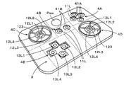
図1は、この発明による第1の実施形態の入力デバイス1を、当該入力デバイス1の斜め上方から見た斜視図である。この例の入力デバイス1は、ゲームコントローラとして用いられる場合を想定している。 [First Embodiment]
FIG. 1 is a perspective view of theinput device 1 of the first embodiment according to the present invention as viewed from diagonally above the input device 1. The input device 1 in this example is assumed to be used as a game controller.
図1は、この発明による第1の実施形態の入力デバイス1を、当該入力デバイス1の斜め上方から見た斜視図である。この例の入力デバイス1は、ゲームコントローラとして用いられる場合を想定している。 [First Embodiment]
FIG. 1 is a perspective view of the
この実施形態の入力デバイス1は、薄板状の外観を備えており、上面側が開口とされている枠ケース2内に、入力デバイス本体3が収納されて構成されている。
The input device 1 of this embodiment has a thin plate-like appearance, and the input device main body 3 is housed in a frame case 2 having an opening on the upper surface side.
この実施形態の入力デバイス1は、入力デバイス本体3の上面の、図1において点線で示すように互いに重複しない領域(図1における点線参照)のそれぞれに、この例では互いに異なる態様の操作を受け付ける複数個の操作入力受付部、図1の例では、5個の操作入力受付部4A,4B,4C,4D,4Eが配設されて構成されている。なお、図1の点線は、複数の操作入力受付部が互いに重複しない領域に配設されることを明確に示すために便宜的に記したものであり、入力デバイス本体3の上面に実際的に点線の境界が描かれているわけではない。
The input device 1 of this embodiment accepts operations of different modes in this example in each of the regions on the upper surface of the input device main body 3 that do not overlap each other (see the dotted line in FIG. 1) as shown by the dotted line in FIG. A plurality of operation input receiving units, in the example of FIG. 1, five operation input receiving units 4A, 4B, 4C, 4D, 4E are arranged and configured. The dotted line in FIG. 1 is for convenience to clearly show that a plurality of operation input receiving units are arranged in a region where they do not overlap with each other, and is actually drawn on the upper surface of the input device main body 3. The dotted boundaries are not drawn.
そして、この例の入力デバイス1においては、入力デバイス本体3は、従来型の押しボタンスイッチPswも、さらに、5個の操作入力受付部4A,4B,4C,4D,4Eが配設されている領域とは別の領域に設けられる構成とされている。
In the input device 1 of this example, the input device main body 3 is provided with a conventional push button switch Psw and five operation input receiving units 4A, 4B, 4C, 4D, 4E. It is configured to be provided in an area different from the area.
操作入力受付部4A,4B,4C,4D,4Eは、1個あるいは複数個の操作部を備えて構成され、1次元、2次元、あるいは3次元のいずれかの空間における操作を受け付けることができるように構成されている。
The operation input receiving unit 4A, 4B, 4C, 4D, 4E is configured to include one or more operation units, and can receive operations in any one-dimensional, two-dimensional, or three-dimensional space. It is configured as follows.
そして、この実施形態においては、5個の操作入力受付部4A,4B,4C,4D,4Eのそれぞれについて、操作部の数、及び操作部の操作空間の違いに応じて、予め、受け付けられる操作の態様が定められている。この場合に、操作入力受付部4A,4B,4C,4D,4Eのそれぞれが受け付ける操作の態様としては、1種類に限らず、複数種の操作の態様が定められている。
Then, in this embodiment, operations that are accepted in advance for each of the five operation input receiving units 4A, 4B, 4C, 4D, and 4E according to the number of operation units and the difference in the operation space of the operation units. Aspects are defined. In this case, the mode of the operation received by each of the operation input receiving units 4A, 4B, 4C, 4D, and 4E is not limited to one type, and a plurality of types of operation modes are defined.
そして、入力デバイス1は、操作入力受付部4A,4B,4C,4D,4Eのそれぞれで受け付けた操作の態様を検出し、検出した操作の態様に応じて異なるコントロール信号を送出するように構成されている。
Then, the input device 1 is configured to detect the mode of the operation received by each of the operation input receiving units 4A, 4B, 4C, 4D, and 4E, and send out different control signals according to the detected mode of the operation. ing.
図1の例では、入力デバイス1の入力デバイス本体3の上面の操作入力受付部4Aの領域においては、横方向に2個、縦方向に2個の合計4個の押しボタン操作部11が、菱形を形成するように配設されて構成されている。押しボタン操作部11は、入力デバイス本体3の上面に直交する高さ方向の位置を変更する操作を受け付けるための操作子11Hを備える。この押しボタン操作部11が受け付ける操作は、入力デバイス本体3の上面上の位置は変えずに高さ方向の位置のみを変更する操作であるので、ここでは1次元の空間の操作と定義する。
In the example of FIG. 1, in the area of the operation input receiving unit 4A on the upper surface of the input device main body 3 of the input device 1, a total of four push button operation units 11 of two in the horizontal direction and two in the vertical direction are provided. It is arranged and configured to form a rhombus. The push button operation unit 11 includes an operator 11H for accepting an operation of changing a position in the height direction orthogonal to the upper surface of the input device main body 3. Since the operation accepted by the push button operation unit 11 is an operation of changing only the position in the height direction without changing the position on the upper surface of the input device main body 3, it is defined here as an operation of a one-dimensional space.
入力デバイス本体3の上面の操作入力受付部4Bの領域においては、横方向に2個の押しボタン操作部11が並べられて配設されて構成されている。
In the area of the operation input reception unit 4B on the upper surface of the input device main body 3, two push button operation units 11 are arranged side by side in the horizontal direction.
入力デバイス本体3の上面の操作入力受付部4C及び操作入力受付部4Dの領域においては、それぞれ1個の指挿入操作部12が配設されて構成されている。この例の指挿入操作部12は、使用者が指、例えば親指を挿入する部分を備える操作子12Hを備え、使用者が、その操作子12Hの、入力デバイス本体3の上面における位置を縦方向及び横方向に変更可能とすると共に、入力デバイス本体3の上面に直交する高さ方向の位置を変更する操作を受け付けることができる3次元操作部の構成されている。
In the area of the operation input reception unit 4C and the operation input reception unit 4D on the upper surface of the input device main body 3, one finger insertion operation unit 12 is arranged and configured. The finger insertion operation unit 12 of this example includes an operator 12H including a portion for inserting a finger, for example, a thumb by the user, and the user vertically positions the position of the operator 12H on the upper surface of the input device main body 3. It is configured as a three-dimensional operation unit that can be changed in the horizontal direction and can accept an operation of changing the position in the height direction orthogonal to the upper surface of the input device main body 3.
入力デバイス1の入力デバイス本体3の上面の操作入力受付部4Eの領域においては、1個の十字型操作部13が配設されて構成されている。十字型操作部13は、この実施形態では、入力デバイス本体3の上面における縦方向と横方向とにクロスする十字型の操作子13Hを備える。
In the area of the operation input receiving unit 4E on the upper surface of the input device main body 3 of the input device 1, one cross-shaped operation unit 13 is arranged and configured. In this embodiment, the cross-shaped operation unit 13 includes a cross-shaped operator 13H that crosses in the vertical direction and the horizontal direction on the upper surface of the input device main body 3.
そして、使用者が、十字型の操作子13Hの上端部13H1,右端部13H2,下端部13H3,左端部13H4(図1参照)の4の端部のいずれかを押下することで、十字の交差点位置を支点として、入力デバイス本体3の上面における縦方向及び横方向に、十字型の操作子13Hをシーソー運動させることができるように構成されている。
Then, the user presses any of the four ends of the upper end 13H1, the right end 13H2, the lower end 13H3, and the left end 13H4 (see FIG. 1) of the cross-shaped operator 13H to cross the cross. With the position as a fulcrum, the cross-shaped operator 13H can be seesaw-moved in the vertical and horizontal directions on the upper surface of the input device main body 3.
なお、この例の十字型操作部13は、2次元操作部の構成とすることもできるが、この実施形態では、後述するように、十字型の操作子13Hの上端部13H1側、下端部13H3側、左端部13H4側あるいは右端部13H2側の操作において、押しボタン操作部11と同様に、それぞれの端部の高さ位置を変更することができるようにして、3次元操作部の構成としている。
The cross-shaped operation unit 13 in this example may be configured as a two-dimensional operation unit, but in this embodiment, as will be described later, the upper end portion 13H1 side and the lower end portion 13H3 of the cross-shaped operator 13H Similar to the push button operation unit 11, the height position of each end can be changed in the operation on the side, the left end portion 13H4 side, or the right end portion 13H2 side, and the three-dimensional operation unit is configured. ..
図3は、この実施形態の入力デバイス1の特に入力デバイス本体3の構成例を説明するための分解斜視図である。ただし、この図3においては、各操作入力受付部4A,4B,4C,4D,4Eの操作部11,12,13は取り外した状態を示している。
FIG. 3 is an exploded perspective view for explaining a configuration example of the input device 1 of this embodiment, particularly the input device main body 3. However, in FIG. 3, the operation units 11, 12, and 13 of the operation input reception units 4A, 4B, 4C, 4D, and 4E are shown in a removed state.
この実施形態の入力デバイス本体3は、回路基板31の上に、位置検出センサ32、保護カバー33、操作部保持部材34が積層されるようにして構成されている。
The input device main body 3 of this embodiment is configured such that a position detection sensor 32, a protective cover 33, and an operation unit holding member 34 are laminated on a circuit board 31.
図3に示すように、枠ケース2の底部には、回路基板31が収納される。この回路基板31には、後述するように、位置検出回路100と、操作情報処理回路200と、無線通信部300などを含む電子回路(図8参照)が形成されている。また、従来型の押しボタンスイッチPswが、この回路基板31上の所定の位置に配設されている。
As shown in FIG. 3, the circuit board 31 is housed in the bottom of the frame case 2. As will be described later, the circuit board 31 is formed with an electronic circuit (see FIG. 8) including a position detection circuit 100, an operation information processing circuit 200, a wireless communication unit 300, and the like. Further, a conventional push button switch Psw is arranged at a predetermined position on the circuit board 31.
この回路基板31の上に、位置検出センサ32が重ねられるように配設される。この例の位置検出センサ32は、電磁誘導方式の位置検出センサの構成とされている。位置検出センサ32は、この例ではフレキシブル基板に複数個のループコイルが配設されて構成されている。この位置検出センサ32の上面は、センサカバー33で覆われて保護されている。なお、この実施形態では、位置検出センサ32及びセンサカバー33には、回路基板31に配設されている押しボタンスイッチPswの押下操作部を挿通させるための貫通孔32a及び33aが穿かれている。
The position detection sensor 32 is arranged so as to be overlapped on the circuit board 31. The position detection sensor 32 in this example is configured as an electromagnetic induction type position detection sensor. In this example, the position detection sensor 32 is configured by disposing a plurality of loop coils on a flexible substrate. The upper surface of the position detection sensor 32 is covered and protected by the sensor cover 33. In this embodiment, the position detection sensor 32 and the sensor cover 33 are provided with through holes 32a and 33a for inserting the push operation portion of the push button switch Psw provided on the circuit board 31. ..
位置検出センサ32の複数個のループコイルは、図示を省略する例えばフレキシブル基板により位置検出回路100に電気的に接続されており、位置検出回路100で、当該位置検出センサ32の位置検出領域における位置指示体の指示位置を検出するように構成されている。
The plurality of loop coils of the position detection sensor 32 are electrically connected to the position detection circuit 100 by, for example, a flexible substrate (not shown), and the position in the position detection circuit 100 in the position detection region of the position detection sensor 32. It is configured to detect the indicated position of the indicator.
そして、この実施形態では、位置検出センサ32の位置検出領域の全域に重畳する状態で、位置検出センサ32の上には、センサカバー33を介して操作部保持部材34が重ねられて配設されている。この操作部保持部34の上面が、入力デバイス本体3の上面であり、この操作部保持部34上に、前述した操作入力受付部4A,4B,4C,4D,4Eが形成されている。なお、この実施形態では、この操作部保持部34にも、回路基板31に配設されている押しボタンスイッチPswの押下操作部を挿通させるための貫通孔34aが穿かれている。
In this embodiment, the operation unit holding member 34 is superposed on the position detection sensor 32 via the sensor cover 33 in a state of being superimposed on the entire position detection region of the position detection sensor 32. ing. The upper surface of the operation unit holding unit 34 is the upper surface of the input device main body 3, and the operation input receiving units 4A, 4B, 4C, 4D, and 4E described above are formed on the operation unit holding unit 34. In this embodiment, the operation portion holding portion 34 is also provided with a through hole 34a for inserting the push operation portion of the push button switch Psw provided on the circuit board 31.
この操作部保持部材34は、その上面の操作入力受付部4A,4B,4C,4D,4Eの領域のそれぞれに、図3に示すように、操作入力受付部4A,4B,4C,4D,4Eの操作部11,12,13のそれぞれを保持固定するためのスペースを構成する凹部41A,41B,41C,41D,41Eが形成されている。
As shown in FIG. 3, the operation unit holding member 34 is provided in each of the areas of the operation input reception units 4A, 4B, 4C, 4D, and 4E on the upper surface thereof, as shown in FIG. 3, the operation input reception units 4A, 4B, 4C, 4D, 4E. Recesses 41A, 41B, 41C, 41D, 41E forming a space for holding and fixing each of the operation units 11, 12, and 13 of the above are formed.
また、操作部保持部材34の操作入力受付部4Cの領域及び操作入力受付部4Dの領域には、指挿入操作部12を保持固定するための円形の凹部41C及び凹部41Dがそれぞれ形成されている。さらに、操作部保持部材34の操作入力受付部4Eの領域には、十字型操作子13Hに対応する十字型の凹部41Eが形成されている。
Further, in the area of the operation input receiving unit 4C and the area of the operation input receiving unit 4D of the operation unit holding member 34, circular recesses 41C and recesses 41D for holding and fixing the finger insertion operation unit 12 are formed, respectively. .. Further, a cross-shaped recess 41E corresponding to the cross-shaped operator 13H is formed in the area of the operation input receiving unit 4E of the operation unit holding member 34.
そして、押しボタン操作部11、指挿入操作部12及び十字型操作部13のそれぞれは、この実施形態では、位置検出センサ32に対する位置指示部を備えている。
Then, each of the push button operation unit 11, the finger insertion operation unit 12, and the cross-shaped operation unit 13 is provided with a position indicating unit for the position detection sensor 32 in this embodiment.
押しボタン操作部11、指挿入操作部12及び十字型操作部13のそれぞれが備える位置検出センサに対する位置指示部は、この実施形態では、位置検出センサ32が電磁誘導方式の位置検出センサであることから、位置検出センサと電磁誘導結合によりインタクラクションする位置指示コイルとされる。位置指示コイルのそれぞれは、コンデンサと接続されて共振回路を構成し、位置検出センサとインタラクションする。この場合に、この実施形態では、共振回路の周波数は、位置指示コイルのそれぞれ毎に異なるように構成され、周波数の違いにより、位置検出センサでは、いずれの位置指示コイルとインタクラクションしているかを検出することができるように構成されている。
In this embodiment, the position detection sensor 32 is an electromagnetic induction type position detection sensor for the position detection sensor provided by each of the push button operation unit 11, the finger insertion operation unit 12, and the cross-shaped operation unit 13. Therefore, it is a position indicating coil that interacts with the position detection sensor by electromagnetic induction coupling. Each of the position-indicating coils is connected to a capacitor to form a resonant circuit and interacts with the position detection sensor. In this case, in this embodiment, the frequency of the resonance circuit is configured to be different for each of the position indicating coils, and the position detection sensor determines which position indicating coil is interacting with the position indicating coil due to the difference in frequency. It is configured to be detectable.
押しボタン操作部11は、1次元の空間の操作である高さ方向の操作を受け付け、その操作を指示することができればよいので、1個の位置指示コイルを備える。これに対して、指挿入操作部12及び十字型操作部13は、入力デバイス本体3の上面の縦方向及び横方向、さらに、高さ方向の3次元の空間の操作を受け付ける必要があるので、複数個、この例では4個の位置指示コイルを備える。つまり、操作部11~13のそれぞれが備える位置指示コイルの数は、それぞれの操作部11~13が受け付ける操作の態様に応じたものとされる。
The push button operation unit 11 is provided with one position indicating coil as long as it can accept an operation in the height direction, which is a one-dimensional space operation, and instruct the operation. On the other hand, the finger insertion operation unit 12 and the cross-shaped operation unit 13 need to accept operations in the three-dimensional space in the vertical and horizontal directions and the height direction of the upper surface of the input device main body 3. A plurality of position indicating coils, in this example, four position indicating coils are provided. That is, the number of position indicating coils provided in each of the operation units 11 to 13 is determined according to the mode of operation accepted by each of the operation units 11 to 13.
図2は、操作入力受付部4A,4B,4C,4D,4Eの各操作部11,12,13に設けられる位置指示コイルについての操作部保持部材34における配置例を示す図である。この図2は、操作入力受付部4A,4B,4C,4D,4Eの各操作部11,12,13の各操作子11H,12H,13Hを取り外して、位置指示コイルの配置状態が分かるように示した図である。
FIG. 2 is a diagram showing an arrangement example of the operation unit holding member 34 for the position indicating coils provided in the operation units 11, 12, and 13 of the operation input reception units 4A, 4B, 4C, 4D, and 4E. In FIG. 2, the controls 11H, 12H, and 13H of the operation units 11, 12, and 13 of the operation input receiving units 4A, 4B, 4C, 4D, and 4E are removed so that the arrangement state of the position indicating coil can be understood. It is a figure shown.
[押しボタン操作部11の構成例]
押しボタン操作部11は、上述のように、1個の位置指示コイル11Lを備える。この位置指示コイル11Lは、図2に示すように、操作部保持部34の操作入力受付部4A及び4Bの領域のそれぞれの4個及び2個の円形の凹部41A及び41Bのそれぞれ内の、この例ではほぼ中央に設けられる。そして、位置指示コイル11Lは、操作子11Hの押下操作により、操作部保持部34の上面に直交する方向である高さ方向に移動可能となるような状態で、押しボタン操作部11に設けられる。 [Configuration example of push button operation unit 11]
As described above, the pushbutton operation unit 11 includes one position indicating coil 11L. As shown in FIG. 2, the position indicating coil 11L is located in each of the four and two circular recesses 41A and 41B in the regions of the operation input receiving portions 4A and 4B of the operating portion holding portion 34, respectively. In the example, it is installed almost in the center. The position indicating coil 11L is provided on the push button operation unit 11 in a state in which the position indicating coil 11L can be moved in the height direction, which is a direction orthogonal to the upper surface of the operation unit holding unit 34, by the pressing operation of the operator 11H. ..
押しボタン操作部11は、上述のように、1個の位置指示コイル11Lを備える。この位置指示コイル11Lは、図2に示すように、操作部保持部34の操作入力受付部4A及び4Bの領域のそれぞれの4個及び2個の円形の凹部41A及び41Bのそれぞれ内の、この例ではほぼ中央に設けられる。そして、位置指示コイル11Lは、操作子11Hの押下操作により、操作部保持部34の上面に直交する方向である高さ方向に移動可能となるような状態で、押しボタン操作部11に設けられる。 [Configuration example of push button operation unit 11]
As described above, the push
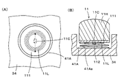
図4は、押しボタン操作部11の構成例を説明するための図である。図4は、操作部保持部34の上面の操作入力受付部4Aの領域の凹部41Aに配設されている押しボタン操作部11の場合を示している。操作入力受付部4Bの領域の凹部41Bに配設されている押しボタン操作部11も同様の構成を有するので、ここでは説明を省略する。
FIG. 4 is a diagram for explaining a configuration example of the push button operation unit 11. FIG. 4 shows the case of the push button operation unit 11 arranged in the recess 41A in the area of the operation input reception unit 4A on the upper surface of the operation unit holding unit 34. Since the push button operation unit 11 arranged in the recess 41B in the area of the operation input reception unit 4B has the same configuration, the description thereof will be omitted here.
図4(A)は、操作部11の操作子11Hを外した状態で、操作部保持部34の上面に直交する方向の真上から見た図であり、図4(B)は、操作子11Hを装着した状態の押しボタン操作部11の縦断面(操作部保持部34の上面に直交する方向の面で切断した断面)を示す図である。
FIG. 4 (A) is a view seen from directly above in the direction orthogonal to the upper surface of the operation unit holding unit 34 with the operator 11H of the operation unit 11 removed, and FIG. 4 (B) is a view of the operator. It is a figure which shows the vertical cross section of the push button operation part 11 (the cross section cut in the plane in the direction orthogonal to the upper surface of the operation part holding part 34) in the state which 11H is attached.
この例では、位置指示コイル11Lは、円形の凹部41Aの内径よりも若干小径の円形のフレキシブル基板111の下面に配設されている。この場合に、位置指示コイル11Lは、線材を1回あるいは複数回巻回したものを、フレキシブル基板111の下面に被着して設けられる。なお、フレキシブル基板111の下面に導体パターンを1回あるいは複数回巻回したものとして、位置指示コイル11Lを形成するようにすることもできる。
In this example, the position indicating coil 11L is arranged on the lower surface of the circular flexible substrate 111 having a diameter slightly smaller than the inner diameter of the circular recess 41A. In this case, the position indicating coil 11L is provided by winding a wire rod once or a plurality of times on the lower surface of the flexible substrate 111. It is also possible to form the position indicating coil 11L by winding the conductor pattern once or a plurality of times on the lower surface of the flexible substrate 111.
そして、図4(A)及び(B)に示すように、位置指示コイル11Lの巻き始め端及び巻き終わり端は、フレキシブル基板111の下面に設けられるコンデンサ11Cの一端及び他端に接続される。これにより、位置指示コイル11Lとコンデンサ11Cとは共振回路を構成する。
Then, as shown in FIGS. 4A and 4B, the winding start end and winding end end of the position indicating coil 11L are connected to one end and the other end of the capacitor 11C provided on the lower surface of the flexible substrate 111. As a result, the position indicating coil 11L and the capacitor 11C form a resonance circuit.
そして、フレキシブル基板111は、その上面側が、この例では円柱形状の操作子11Hの端面に、例えば接着材により接着される。そして、操作子11Hに接着されて取り付けられたフレキシブル基板111と、操作部保持部34の凹部41Aの底面41Aaとの間に弾性部材、この例ではコイルばね112が設けられる。このコイルばね112は、操作子11Hが底面41Aaに直交する高さ方向に押下されたときに、弾性的に変位し、押下力がなくなったときに、操作子11Hを元の高さ位置に復帰させるための復帰用ばねである。
Then, the upper surface side of the flexible substrate 111 is adhered to the end surface of the cylindrical operator 11H in this example by, for example, an adhesive. An elastic member, in this example, a coil spring 112, is provided between the flexible substrate 111 bonded and attached to the actuator 11H and the bottom surface 41Aa of the recess 41A of the operating portion holding portion 34. The coil spring 112 elastically displaces when the operator 11H is pressed in the height direction orthogonal to the bottom surface 41Aa, and returns the operator 11H to the original height position when the pressing force is lost. It is a return spring for making it.
押しボタン操作部11は、以上のように構成されるので、操作子11Hを使用者が押下操作することで、位置指示コイル11Lの凹部41Aの底面41Aaとの距離、つまり高さ位置を変更することができる。
Since the push button operation unit 11 is configured as described above, the user presses the operator 11H to change the distance from the bottom surface 41Aa of the recess 41A of the position indicating coil 11L, that is, the height position. be able to.
この実施形態では、操作部保持部34の下方に設けられる電磁誘導方式の位置検出センサ32は、後述するように、押しボタン操作部11の位置指示コイル11Lとコンデンサ11Cとで構成される共振回路に送信し、共振回路からの信号を受信する。
In this embodiment, the electromagnetic induction type position detection sensor 32 provided below the operation unit holding unit 34 is a resonance circuit composed of a position indicating coil 11L of the push button operation unit 11 and a capacitor 11C, as will be described later. And receive the signal from the resonant circuit.
この実施形態では、上述のようにして、電磁誘導方式の位置検出センサ32は、押しボタン操作部11の位置指示コイル11Lと電磁結合して、位置指示コイル11Lから帰還される信号を受信する。この場合に、位置検出センサ32と位置指示コイル11Lとの電磁結合の強度は位置指示コイル11Lの高さ位置に応じて変わるので、位置検出センサ32で受信する位置指示コイル11Lからの信号のレベルが、位置指示コイル11Lの高さ位置に応じて変わる。
In this embodiment, as described above, the position detection sensor 32 of the electromagnetic induction method electromagnetically couples with the position indicating coil 11L of the push button operation unit 11 and receives the signal returned from the position indicating coil 11L. In this case, the strength of the electromagnetic coupling between the position detection sensor 32 and the position indicator coil 11L changes according to the height position of the position indicator coil 11L, so that the level of the signal from the position indicator coil 11L received by the position detection sensor 32 changes. However, it changes according to the height position of the position indicating coil 11L.
図5は、押しボタン操作部11の他の構成例を説明するための図であり、この例は、押しボタン操作部11の操作子11Hを押下したときの押し圧を、後述する位置検出回路100で検出することできるように構成した例である。この図5の例において、図4の例と同一部分には、同一参照符号を付してその詳細な説明は省略する。
FIG. 5 is a diagram for explaining another configuration example of the push button operation unit 11, and in this example, the pressing pressure when the operation element 11H of the push button operation unit 11 is pressed is a position detection circuit described later. It is an example configured so that it can be detected by 100. In the example of FIG. 5, the same parts as those of the example of FIG. 4 are designated by the same reference numerals, and detailed description thereof will be omitted.
すなわち、図5の例の押しボタン操作部11´においては、フレキシブル基板111´の中心位置に貫通孔111aを設ける。そして、コンデンサ11Cは、図5に示すように、フレキシブル基板111´において、この貫通孔111aの位置を避けた位置に配設する。
That is, in the push button operation unit 11'in the example of FIG. 5, a through hole 111a is provided at the center position of the flexible substrate 111'. Then, as shown in FIG. 5, the capacitor 11C is arranged in the flexible substrate 111'at a position avoiding the position of the through hole 111a.
そして、この例では、操作子11H´のフレキシブル基板111´との接合面側の中央に、圧力検出部113を設ける。この圧力検出部113は、この例では、例えば特開2016-126503号公報に記載されている周知の構成の可変容量コンデンサを用いる。この圧力検出部113で構成される可変容量コンデンサは、位置指示コイル11Lとコンデンサ11Cとに並列に接続されて、共振回路の一部を構成するようにされる。そして、圧力伝達部材114が、貫通孔111aを介して圧力検出部113に嵌合されている。
Then, in this example, the pressure detection unit 113 is provided at the center of the actuator 11H'on the joint surface side with the flexible substrate 111'. In this example, the pressure detection unit 113 uses, for example, a variable capacitor having a well-known configuration described in Japanese Patent Application Laid-Open No. 2016-126503. The variable capacitance capacitor configured by the pressure detection unit 113 is connected in parallel to the position indicating coil 11L and the capacitor 11C so as to form a part of the resonance circuit. Then, the pressure transmission member 114 is fitted to the pressure detection unit 113 via the through hole 111a.
したがって、使用者がボタン操作部11´を押下操作すると、当該印加された圧力は、圧力伝達部材114を介して圧力検出部113に伝達され、可変容量コンデンサの容量変化として検出される。
Therefore, when the user presses the button operation unit 11', the applied pressure is transmitted to the pressure detection unit 113 via the pressure transmission member 114, and is detected as a capacitance change of the variable capacitance capacitor.
この図5の例の押しボタン操作部11´は、以上のように構成されるので、操作子11H´を使用者が押下操作することで、位置指示コイル11Lの凹部41Aの底面41Aaとの距離である高さを変更することができると共に、使用者の操作子11H´に対する押し圧が、圧力検出部113の可変容量コンデンサの容量変化として検出される。
Since the push button operation unit 11'in the example of FIG. 5 is configured as described above, the user presses the operator 11H'to operate the position indicating coil 11L at a distance from the bottom surface 41Aa of the recess 41A. The height can be changed, and the push pressure against the operator 11H'is detected as a capacitance change of the variable capacitance capacitor of the pressure detection unit 113.
[指挿入操作部12の構成例]
指挿入操作部12は、図2及び図6(A)に示すように、4個の位置指示コイル12L1,12L2,12L3,12L4を備える。 [Structure example of finger insertion operation unit 12]
As shown in FIGS. 2 and 6A, the fingerinsertion operation unit 12 includes four position indicating coils 12L1, 12L2, 12L3, 12L4.
指挿入操作部12は、図2及び図6(A)に示すように、4個の位置指示コイル12L1,12L2,12L3,12L4を備える。 [Structure example of finger insertion operation unit 12]
As shown in FIGS. 2 and 6A, the finger
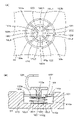
図6は、指挿入操作部12の構成例を説明するための図である。なお、図6は、操作部保持部34の上面の操作入力受付部4Cの凹部41Cに配設されている指挿入操作部12の場合を示している。操作入力受付部4Dの凹部41Dに配設されている指挿入操作部12も同様の構成を有するので、ここでは説明を省略する。
FIG. 6 is a diagram for explaining a configuration example of the finger insertion operation unit 12. Note that FIG. 6 shows the case of the finger insertion operation unit 12 arranged in the recess 41C of the operation input reception unit 4C on the upper surface of the operation unit holding unit 34. Since the finger insertion operation unit 12 arranged in the recess 41D of the operation input reception unit 4D has the same configuration, the description thereof will be omitted here.
図6(A)は、指挿入操作部12の操作子12Hを外した状態で、操作部保持部34の上面に直交する方向の真上から見た図であり、図6(B)は、操作子12Hを装着した状態の指挿入操作部12の縦断面(操作部保持部34の上面に直交する方向の面で切断した断面)を示す図である。
FIG. 6A is a view seen from directly above in a direction orthogonal to the upper surface of the operation unit holding unit 34 with the operator 12H of the finger insertion operation unit 12 removed, and FIG. 6B is a view. It is a figure which shows the vertical cross section of the finger insertion operation part 12 (the cross section cut in the plane in the direction orthogonal to the upper surface of the operation part holding part 34) with the operation element 12H attached.
4個の位置指示コイル12L1~12L4は、図2及び図6(A)に示すように、操作部保持部34の操作入力受付部4Cの領域の円形の凹部41Cのそれぞれ内に設けられる。
As shown in FIGS. 2 and 6A, the four position indicating coils 12L1 to 12L4 are provided in each of the circular recesses 41C in the region of the operation input receiving unit 4C of the operating unit holding unit 34.
この場合に、4個の位置指示コイル12L1~12L4は、凹部41Cの円形の底面が、円周方向に90度角範囲ごとに4分割され、その90度角範囲の分割角範囲のそれぞれに分離されて配置される。
In this case, in the four position indicating coils 12L1 to 12L4, the circular bottom surface of the recess 41C is divided into four in each 90-degree angle range in the circumferential direction, and the four position-indicating coils 12L1 to 12L4 are separated into each of the 90-degree angle ranges. And placed.
そして、これら4個の位置指示コイル12L1~12L4は、操作子12Hの操作により、操作部保持部34の上面の縦方向及び横方向に移-動が可能であると共に、操作部保持部34の上面に直交する方向である高さ方向に移動可能となるような状態で、指挿入操作部12に設けられる。
The four position indicating coils 12L1 to 12L4 can be moved in the vertical and horizontal directions on the upper surface of the operation unit holding unit 34 by operating the actuator 12H, and the operation unit holding unit 34 can be moved in the vertical direction and the horizontal direction. The finger insertion operation unit 12 is provided so as to be movable in the height direction, which is a direction orthogonal to the upper surface.
この例では、図6(A)及び(B)に示すように、4個の位置指示コイル12L1~12L4は、円形の凹部41Cの内径よりも小径の円形のフレキシブル基板121の下面に配設されている。この場合に、4個の位置指示コイル12L1~12L4のそれぞれは、線材を1回あるいは複数回巻回したものを、フレキシブル基板121の下面に被着して設けられる。この場合、4個の位置指示コイル12L1~12L4のそれぞれは、図6(A)に示すように、扇型形状に巻回されて、円形のフレキシブル基板121の下面のそれぞれ90度角範囲に配設される。
In this example, as shown in FIGS. 6A and 6B, the four position indicating coils 12L1 to 12L4 are arranged on the lower surface of the circular flexible substrate 121 having a diameter smaller than the inner diameter of the circular recess 41C. ing. In this case, each of the four position indicating coils 12L1 to 12L4 is provided by applying a wire rod wound once or a plurality of times to the lower surface of the flexible substrate 121. In this case, as shown in FIG. 6A, each of the four position indicating coils 12L1 to 12L4 is wound in a fan shape and arranged in a 90 degree angle range on the lower surface of the circular flexible substrate 121. Will be set up.
そして、図6(A)及び(B)に示すように、位置指示コイル12L1,12L2,12L3,12L4は、フレキシブル基板121の下面に設けられるコンデンサ12C1,12C2,12C3,12C4のそれぞれに接続されて共振回路を構成する。それぞれの共振回路が位置検出センサと電磁誘導結合することで、位置指示コイル12L1~12L4のそれぞれは、位置検出センサ32に対して位置指示をするように構成される。
Then, as shown in FIGS. 6A and 6B, the position indicating coils 12L1, 12L2, 12L3, 12L4 are connected to each of the capacitors 12C1, 12C2, 12C3, 12C4 provided on the lower surface of the flexible substrate 121. It constitutes a resonance circuit. Each of the position indicating coils 12L1 to 12L4 is configured to instruct the position to the position detection sensor 32 by electromagnetic induction coupling of each resonance circuit with the position detection sensor.
そして、図6(B)に示すように、フレキシブル基板121と、操作部保持部34の凹部41Cの底面41Caとの間に弾性部材、この例ではコイルばね122が設けられる。このコイルばね122は、操作子12Hが底面41Caに直交する高さ方向に押下されたときに弾性的に変位すると共に、復帰用ばねとして働く。
Then, as shown in FIG. 6B, an elastic member, in this example, a coil spring 122 is provided between the flexible substrate 121 and the bottom surface 41Ca of the recess 41C of the operation unit holding portion 34. The coil spring 122 elastically displaces when the operator 12H is pressed in the height direction orthogonal to the bottom surface 41Ca, and also acts as a return spring.
そして、この例では、フレキシブル基板121は、操作部保持部34の上面に平行な方向であって、操作部保持部34の上面の縦方向及び横方向に移動することができるような状態で、凹部41C内に保持される。
Then, in this example, the flexible substrate 121 is in a direction parallel to the upper surface of the operation unit holding portion 34 and can be moved in the vertical direction and the horizontal direction of the upper surface of the operation unit holding unit 34. It is held in the recess 41C.
すなわち、この例では、フレキシブル基板121は、弾性的に伸縮し易い弾性材料、例えば弾性ゴムからなる弾性保持部材123に取り付けられている。弾性保持部材123は、円形の凹部41Cの中心位置に、操作子12Hとの結合用部123aを備える。また、弾性保持部材123は、この結合用部123aから、凹部41Cの底面41Caに平行な方向であって、かつ、互いに直交する方向に延伸される4個の帯状部123b,123c,123d,123eを備える。
That is, in this example, the flexible substrate 121 is attached to an elastic holding member 123 made of an elastic material that easily expands and contracts elastically, for example, elastic rubber. The elastic holding member 123 includes a coupling portion 123a with the operator 12H at the center position of the circular recess 41C. Further, the elastic holding member 123 has four strip-shaped portions 123b, 123c, 123d, 123e extending from the coupling portion 123a in a direction parallel to the bottom surface 41Ca of the recess 41C and in a direction orthogonal to each other. To prepare for.
そして、弾性保持部材123の4個の帯状部123b,123c,123d,123eの間は、結合用部123aの中心位置から所定の半径の円周に沿って形成される4個の弧状部123f,123g,123h,123iにより結合されている。4個の弧状部123f,123g,123h,123iの、結合用部123aの中心位置からの半径は、この例では、円形のフレキシブル基板121の半径と同一、あるいは若干小さい半径とされている。
Then, between the four strips 123b, 123c, 123d, 123e of the elastic holding member 123, the four arc-shaped portions 123f formed along the circumference of a predetermined radius from the center position of the coupling portion 123a, It is bound by 123g, 123h, 123i. The radii of the four arcuate portions 123f, 123g, 123h, 123i from the center position of the coupling portion 123a are the same as or slightly smaller than the radius of the circular flexible substrate 121 in this example.
そして、この例では、図6(A)及び(B)に示すように、円形のフレキシブル基板121の中心位置と、弾性保持部材123の結合用部123aの中心位置とがほぼ一致する状態で、フレキシブル基板121の上面側が、弾性保持部材123に固着される。
Then, in this example, as shown in FIGS. 6A and 6B, the center position of the circular flexible substrate 121 and the center position of the coupling portion 123a of the elastic holding member 123 are substantially the same. The upper surface side of the flexible substrate 121 is fixed to the elastic holding member 123.
そして、弾性保持部材123は、その4個の帯状部123b,123c,123d,123eの先端が、円形の凹部41Cの側壁面41Cb(図6(B)参照)に固着されることにより、凹部41Cに取り付けられている。
The elastic holding member 123 is formed by fixing the tips of its four strips 123b, 123c, 123d, 123e to the side wall surface 41Cb (see FIG. 6B) of the circular recess 41C, thereby fixing the recess 41C. It is attached to.
また、弾性保持部材123の4個の帯状部123b,123c,123d,123eの先端の、円形の凹部41Cの側壁面41Cbにおける高さ方向の固着位置は、図6(B)に示すように、フレキシブル基板121と凹部41Cの底面41Caとの間にコイルばね122が介在していて、操作子12Hに押圧力がかかっていない状態のときの高さ位置とされる。
Further, as shown in FIG. 6, the fixing position in the height direction on the side wall surface 41Cb of the circular recess 41C at the tips of the four strips 123b, 123c, 123d, 123e of the elastic holding member 123 is shown. The coil spring 122 is interposed between the flexible substrate 121 and the bottom surface 41Ca of the recess 41C, and is set to the height position when the operator 12H is not pressed.
そして、図6(B)に示すように、操作子12Hは、弾性保持部材123の結合用部123aにおいて弾性保持部材123と結合される。
Then, as shown in FIG. 6B, the actuator 12H is coupled to the elastic holding member 123 at the coupling portion 123a of the elastic holding member 123.
この図6の例の指挿入操作部12は、以上のように構成されるので、使用者が操作子12Hを、操作部保持部34の上面に平行な縦方向及び横方向に移動させると、弾性保持部材123の結合用部123aが弾性的に操作部保持部34の上面に平行な縦方向及び横方向に移動するように変位し、位置指示コイル12L1~12L4を、その変位方向に位置変化させることができる。また、操作子12Hを使用者が押下操作すると、弾性保持部材123の結合用部123aの高さ方向の位置が弾性的に変位するので、位置指示コイル11Lの凹部41Aの底面41Aaとの距離である高さを変更することができる。
Since the finger insertion operation unit 12 in the example of FIG. 6 is configured as described above, when the user moves the operator 12H in the vertical direction and the horizontal direction parallel to the upper surface of the operation unit holding unit 34, The coupling portion 123a of the elastic holding member 123 is elastically displaced so as to move in the vertical and horizontal directions parallel to the upper surface of the operating portion holding portion 34, and the position indicating coils 12L1 to 12L4 are displaced in the displacement direction. Can be made to. Further, when the user presses the actuator 12H, the position of the coupling portion 123a of the elastic holding member 123 in the height direction is elastically displaced. You can change a certain height.
[十字型操作部13の構成例]
十字型操作部13は、図2及び図7に示すように、4個の位置指示コイル13L1,13L2,13L3,13L4を備える。 [Structure example of cross-shaped operation unit 13]
As shown in FIGS. 2 and 7, thecross-shaped operation unit 13 includes four position indicating coils 13L1, 13L2, 13L3, 13L4.
十字型操作部13は、図2及び図7に示すように、4個の位置指示コイル13L1,13L2,13L3,13L4を備える。 [Structure example of cross-shaped operation unit 13]
As shown in FIGS. 2 and 7, the
図7は、操作部保持部34の上面の操作入力受付部4Eの凹部41Eに配設されている十字型操作部13の構成例を説明するための図である。図7(A)は、十字型操作部13の操作子13Hを外した状態で、操作部保持部34の上面に直交する方向の真上から見た図であり、図7(B)は、操作子13Hを装着した状態の十字型操作部13の縦断面(操作部保持部34の上面に直交する方向の面で切断した断面)を示す図である。
FIG. 7 is a diagram for explaining a configuration example of the cross-shaped operation unit 13 arranged in the recess 41E of the operation input reception unit 4E on the upper surface of the operation unit holding unit 34. 7 (A) is a view seen from directly above in the direction orthogonal to the upper surface of the operation unit holding unit 34 with the operator 13H of the cross-shaped operation unit 13 removed, and FIG. 7 (B) is a view. It is a figure which shows the vertical cross section of the cross-shaped operation part 13 (the cross section cut by the plane in the direction orthogonal to the upper surface of the operation part holding part 34) with the operation element 13H attached.
4個の位置指示コイル13L1~13L4は、図2及び図7に示すように、操作部保持部34の操作入力受付部4Eの領域の十字型の凹部41Eの互いにクロスする凹溝の端部にそれぞれ配置される。
As shown in FIGS. 2 and 7, the four position indicating coils 13L1 to 13L4 are located at the ends of the concave grooves crossing each other in the cross-shaped recess 41E in the region of the operation input receiving portion 4E of the operating portion holding portion 34. Each is placed.
そして、これら4個の位置指示コイル13L1~13L4は、十字型の操作子13Hの操作により、操作部保持部34の上面に直交する方向である高さ方向に移動可能となるような状態で、十字型操作部13に設けられる。
The four position indicating coils 13L1 to 13L4 can be moved in the height direction orthogonal to the upper surface of the operation unit holding portion 34 by the operation of the cross-shaped operator 13H. It is provided in the cross-shaped operation unit 13.
すなわち、この例では、図7(A)及び(B)に示すように、4個の位置指示コイル13L1,13L2,13L3,13L4のそれぞれは、十字型の凹部41Eの凹溝の幅よりも小径の円形のフレキシブル基板1311,1312,1313,1314の下面に配設されている。この場合に、4個の位置指示コイル12L1~12L4のそれぞれは、線材を1回あるいは複数回巻回したものを、フレキシブル基板1311~1314の下面に被着して設けられる。
That is, in this example, as shown in FIGS. 7A and 7B, each of the four position indicating coils 13L1, 13L2, 13L3, 13L4 has a diameter smaller than the width of the groove of the cross-shaped recess 41E. It is arranged on the lower surface of the circular flexible substrate 1311, 1312, 1313, 1314. In this case, each of the four position indicating coils 12L1 to 12L4 is provided by winding a wire rod once or a plurality of times on the lower surface of the flexible substrate 1311 to 1314.
そして、図7(A)及び(B)に示すように、位置指示コイル13L1,13L2,13L3,13L4は、フレキシブル基板1311,1312,1313,1314の下面に設けられるコンデンサ13C1,13C2,13C3,13C4に接続される。これにより、位置指示コイル13L1~13L4のそれぞれと、コンデンサ13C1~13C4のそれぞれとは共振回路を構成し、それぞれの共振回路が位置検出センサと電磁誘導結合することで、位置指示コイル13L1~13L4のそれぞれは、位置検出センサ32に対して位置指示をするように構成される。
Then, as shown in FIGS. 7A and 7B, the position indicating coils 13L1, 13L2, 13L3, 13L4 are the capacitors 13C1, 13C2, 13C3, 13C4 provided on the lower surface of the flexible substrate 1311, 1312, 1313, 1314. Connected to. As a result, each of the position indicating coils 13L1 to 13L4 and each of the capacitors 13C1 to 13C4 form a resonance circuit, and each resonance circuit is electromagnetically induced and coupled to the position detection sensor to form the position indicating coils 13L1 to 13L4. Each is configured to give a position instruction to the position detection sensor 32.
そして、フレキシブル基板1311~1314のそれぞれと、操作部保持部34の凹部41Eの底面41Eaとの間に弾性部材、この例ではコイルばね1321,1322,1323,1324が設けられる。このコイルばね1321,1322,1323,1324は、十字型の操作子13Hの4個の端部13H1,13H2,13H3,13H4(図1及び図7(B)参照)のそれぞれが押下されたときに弾性的に変位し、押下力がなくなったときに、それぞれを元の高さ位置に復帰させるための復帰用ばねである。
An elastic member, in this example, a coil spring 1321, 1322, 1323, 1324 is provided between each of the flexible substrates 1311 to 1314 and the bottom surface 41Ea of the recess 41E of the operation unit holding portion 34. The coil springs 1321, 1322, 1323, 1324 are formed when each of the four ends 13H1, 13H2, 13H3, 13H4 (see FIGS. 1 and 7B) of the cross-shaped operator 13H is pressed. It is a return spring for returning each to the original height position when it is elastically displaced and the pressing force is lost.
そして、この例においては、十字型の操作子13Hの中心位置には、図7(B)に示すように、当該十字型の操作子13Hのシーソー運動の支軸13Hoが形成されている。一方、十字型操作部13の操作入力受付部4Eの凹部41Eの底面41Eaの、凹溝がクロスする中心位置には、図7(A)及び(B)に示すように、十字型の操作子13Hの支軸13Hoの先端を支持受けする支軸受部134が設けられている。
Then, in this example, as shown in FIG. 7B, a support shaft 13Ho of the seesaw movement of the cross-shaped operator 13H is formed at the central position of the cross-shaped operator 13H. On the other hand, as shown in FIGS. 7A and 7B, a cross-shaped operator is located at the center position where the concave groove crosses the bottom surface 41Ea of the concave portion 41E of the operation input receiving unit 4E of the cross-shaped operation unit 13. A support bearing portion 134 that supports and receives the tip of the support shaft 13Ho of 13H is provided.
この図7の例の十字型操作部13は、以上のように構成されるので、使用者が操作子13Hの4個の端部13H1,13H2,13H3,13H4のいずれかを押下操作することで、4個の位置指示コイル13L1,13L2,13L3,13L4のいずれかの、凹部41Eの底面41Eaとの距離、つまり高さ位置を変更することができる。
Since the cross-shaped operation unit 13 in the example of FIG. 7 is configured as described above, the user can press and operate any of the four ends 13H1, 13H2, 13H3, 13H4 of the operator 13H. The distance, that is, the height position of any of the four position indicating coils 13L1, 13L2, 13L3, 13L4 to the bottom surface 41Ea of the recess 41E can be changed.
[入力デバイス1の電子回路構成例]
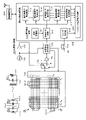
図8は、この実施形態の入力デバイス1の電子回路構成例を示す図である。回路基板31には、位置検出回路100と、操作情報処理回路200と、無線通信部300とが設けられている。図8に示すように、位置検出回路100に対して位置検出センサ32が接続されている。そして、位置検出回路100の出力が操作情報処理回路200に供給され、操作情報処理回路200の出力(コントロール信号)が無線通信部300を通じて、ゲーム機本体やパーソナルコンピュータに送信される。無線通信部300は、この例では、Bluetooth(登録商標)規格の通信方式で無線通信を行う。 [Example of electronic circuit configuration of input device 1]
FIG. 8 is a diagram showing an example of an electronic circuit configuration of theinput device 1 of this embodiment. The circuit board 31 is provided with a position detection circuit 100, an operation information processing circuit 200, and a wireless communication unit 300. As shown in FIG. 8, the position detection sensor 32 is connected to the position detection circuit 100. Then, the output of the position detection circuit 100 is supplied to the operation information processing circuit 200, and the output (control signal) of the operation information processing circuit 200 is transmitted to the game machine main body or the personal computer through the wireless communication unit 300. In this example, the wireless communication unit 300 performs wireless communication by the communication method of the Bluetooth (registered trademark) standard.
図8は、この実施形態の入力デバイス1の電子回路構成例を示す図である。回路基板31には、位置検出回路100と、操作情報処理回路200と、無線通信部300とが設けられている。図8に示すように、位置検出回路100に対して位置検出センサ32が接続されている。そして、位置検出回路100の出力が操作情報処理回路200に供給され、操作情報処理回路200の出力(コントロール信号)が無線通信部300を通じて、ゲーム機本体やパーソナルコンピュータに送信される。無線通信部300は、この例では、Bluetooth(登録商標)規格の通信方式で無線通信を行う。 [Example of electronic circuit configuration of input device 1]
FIG. 8 is a diagram showing an example of an electronic circuit configuration of the
位置検出センサ32は、図8に示すように、この例では、例えばフレキシブル基板上にX軸方向ループコイル群321Xと、Y軸方向ループコイル群321Yとが積層されて構成される。X軸ループコイル群321Xの各ループコイルX1~Xnと、Y軸ループコイル群321Yの各ループコイルY1~Ymのそれぞれは、1ターンの場合もあれば、2ターン以上の複数ターンの場合もある。また、各ループコイル群321X、321Yのループコイルの数n,mも位置検出センサ32のサイズに応じて適宜のものとすることができる。
As shown in FIG. 8, in this example, the position detection sensor 32 is configured by stacking, for example, an X-axis direction loop coil group 321X and a Y-axis direction loop coil group 321Y on a flexible substrate. Each of the loop coils X 1 to X n of the X-axis loop coil group 321X and the loop coils Y 1 to Y m of the Y-axis loop coil group 321Y may have one turn or multiple turns of two or more turns. In some cases. Further, the number n, m of the loop coils of each loop coil group 321X and 321Y can be appropriately set according to the size of the position detection sensor 32.
位置検出回路100は、発振器101と、電流ドライバ102と、選択回路103と、切り替え接続回路104と、受信アンプ105と、位置検出処理回路106とからなる。位置検出センサ32の各ループコイル群321X、321Yのループコイルは、選択回路103に接続される。
The position detection circuit 100 includes an oscillator 101, a current driver 102, a selection circuit 103, a switching connection circuit 104, a reception amplifier 105, and a position detection processing circuit 106. The loop coils of the loop coil groups 321X and 321Y of the position detection sensor 32 are connected to the selection circuit 103.
位置検出処理回路106は、上述した押しボタン操作部11の位置指示コイル11L、指挿入操作部12の位置指示コイル12L1~12L4、十字型操作部13の位置指示コイル13L1~13L4の、位置検出センサ32上における座標位置を検出する。図5の例のように、圧力検出部を操作部が備える場合には、位置検出処理回路106は、圧力を検出する処理も行う。
The position detection processing circuit 106 is a position detection sensor of the position indicator coil 11L of the push button operation unit 11, the position indicator coils 12L1 to 12L4 of the finger insertion operation unit 12, and the position indicator coils 13L1 to 13L4 of the cross-shaped operation unit 13. 32 The coordinate position on the top is detected. When the operation unit includes the pressure detection unit as in the example of FIG. 5, the position detection processing circuit 106 also performs a process of detecting the pressure.
また、位置検出処理回路106は、選択回路103における位置検出センサ32のループコイルの選択、切り替え接続回路104の切り替えを制御すると共に、位置検出及び圧力検出の処理タイミングを制御する機能を備えている。
Further, the position detection processing circuit 106 has a function of controlling the selection of the loop coil of the position detection sensor 32 in the selection circuit 103 and the switching of the switching connection circuit 104, and also controlling the processing timing of the position detection and the pressure detection. ..
位置検出センサ32のX軸方向ループコイル群321X及びY軸方向ループコイル群321Yが選択回路103に接続されている。選択回路103は、2つのループコイル群321X,321Yのうちの一のループコイルを順次選択する。発振器101は、位置指示コイル11L、12L1~12L4、及び13L1~13L4を含む共振回路の共振周波数に応じた周波数の交流信号を発生する。発振器101は、発生した交流信号を、電流ドライバ102に供給する。電流ドライバ102は、発振器101から供給された交流信号を電流に変換して切り替え接続回路104へ送出する。
The X-axis direction loop coil group 321X and the Y-axis direction loop coil group 321Y of the position detection sensor 32 are connected to the selection circuit 103. The selection circuit 103 sequentially selects one of the two loop coil groups 321X and 321Y. The oscillator 101 generates an AC signal having a frequency corresponding to the resonance frequency of the resonance circuit including the position indicating coils 11L, 12L1 to 12L4, and 13L1 to 13L4. The oscillator 101 supplies the generated AC signal to the current driver 102. The current driver 102 converts the AC signal supplied from the oscillator 101 into a current and sends it to the switching connection circuit 104.
切り替え接続回路104は、位置検出処理回路106からの制御により選択回路103で選択されたループコイルが接続される接続先(送信側端子T、受信側端子R)を切り替える。
The switching connection circuit 104 switches the connection destination (transmission side terminal T, reception side terminal R) to which the loop coil selected by the selection circuit 103 is connected by the control from the position detection processing circuit 106.
そして、切り替え接続回路104が、端子T側に切り替えられている場合には、選択回路103により選択されたループコイルに、電流ドライバ102からの電流が供給される。これにより、当該ループコイルにおいて磁界が発生し、位置検出センサ32に対向して配設されている操作部11~13の共振回路に作用させるための信号(電波)を送信する。位置指示コイル11L、12L1~12L4、及び13L1~13L4を含む共振回路の共振周波数は異なる周波数を有しているため、発振器101からの周波数は、順次異なる周波数の交流信号が発生するように構成されている。
Then, when the switching connection circuit 104 is switched to the terminal T side, the current from the current driver 102 is supplied to the loop coil selected by the selection circuit 103. As a result, a magnetic field is generated in the loop coil, and a signal (radio wave) for acting on the resonance circuit of the operation units 11 to 13 arranged facing the position detection sensor 32 is transmitted. Since the resonant frequencies of the resonant circuits including the position indicating coils 11L, 12L1-12L4, and 13L1-13L4 have different frequencies, the frequencies from the oscillator 101 are configured to sequentially generate AC signals of different frequencies. ing.
図8の左上に、操作部11~13の内の押しボタン操作部11の位置指示コイル11L1とコンデンサ11Cとからなる共振回路RC1を、一例として示す。なお、押しボタン操作部11´の場合には、図8の左上の一番右側に示すように、押しボタン操作部11´の位置指示コイル11L1とコンデンサ11Cと圧力検出部113で構成される可変容量コンデンサ113Cとで共振回路RC´が構成される。
In the upper left of FIG. 8, the resonance circuit RC1 including the position indicating coil 11L1 of the push button operation unit 11 in the operation units 11 to 13 and the capacitor 11C is shown as an example. In the case of the push button operation unit 11', as shown on the far right of the upper left of FIG. 8, the variable configuration is composed of the position indicating coil 11L1 of the push button operation unit 11', the capacitor 11C, and the pressure detection unit 113. The resonant circuit RC'is composed of the capacitive capacitor 113C.
操作部11~13の各共振回路は、位置検出センサ32からのそれぞれの周波数の交流信号を電磁誘導結合により受信すると、位置検出センサ32が受信状態になったときに、その受信した信号を位置検出センサ32に帰還させる。
Each resonant circuit of the operation units 11 to 13 receives an AC signal of each frequency from the position detection sensor 32 by electromagnetic induction coupling, and when the position detection sensor 32 is in the reception state, the received signal is positioned. It is fed back to the detection sensor 32.
位置検出処理回路106は、切り替え接続回路104を端子Tに接続して操作部1~13の共振回路に周波数f0の交流信号を電磁誘導結合により送信した後、切り替え接続回路207を端子R側に切り替える。
The position detection processing circuit 106 connects the switching connection circuit 104 to the terminal T, transmits an AC signal having a frequency f0 to the resonance circuits of the operation units 1 to 13 by electromagnetic induction coupling, and then sends the switching connection circuit 207 to the terminal R side. Switch.
すると、操作部11~13の共振回路からの帰還信号により位置検出センサ32のループコイルに発生する誘導電圧は、選択回路103及び切り替え接続回路104を介して受信アンプ105に送られる。受信アンプ105は、ループコイルから供給された誘導電圧を増幅し、受信信号として位置検出処理回路106へ送出する。
Then, the induced voltage generated in the loop coil of the position detection sensor 32 by the feedback signal from the resonance circuit of the operation unit 11 to 13 is sent to the receiving amplifier 105 via the selection circuit 103 and the switching connection circuit 104. The receiving amplifier 105 amplifies the induced voltage supplied from the loop coil and sends it to the position detection processing circuit 106 as a receiving signal.
位置検出処理回路106は、受信アンプ105からの受信信号がいずれのループコイルを選択したときに得られたかを検出することで、当該受信信号の送信元の操作部11~13の共振回路の位置指示コイル11L,12L1~12L4,13L1~13L4の、位置検出センサ32上における座標位置を検出する。そして、位置検出処理回路106は、受信アンプ105からの受信信号の信号レベルを検出する。この受信信号の信号レベルは、操作部11~13のそれぞれの位置指示コイル11L,12L1~12L4,13L1~13L4の高さ位置に対応したレベルを呈する。
The position detection processing circuit 106 detects which loop coil the received signal from the receiving amplifier 105 is obtained when the loop coil is selected, so that the position of the resonance circuit of the operation units 11 to 13 of the transmission source of the received signal is detected. The coordinate positions of the indicator coils 11L, 12L1 to 12L4, 13L1 to 13L4 on the position detection sensor 32 are detected. Then, the position detection processing circuit 106 detects the signal level of the received signal from the receiving amplifier 105. The signal level of this received signal exhibits a level corresponding to the height position of the position indicating coils 11L, 12L1 to 12L4, 13L1 to 13L4 of the operation units 11 to 13, respectively.
また、位置検出処理回路106は、操作部11~13の共振回路が圧力検出部からなる可変容量コンデンサを含む場合には、発振器101からの発信信号により受信信号を同期検波して、それらの間の周波数変位(位相差)を検出することで、操作部に印加されている圧力を検出する。
Further, when the resonance circuit of the operation units 11 to 13 includes a variable capacitance capacitor composed of a pressure detection unit, the position detection processing circuit 106 synchronously detects the received signal by the transmission signal from the oscillator 101, and between them. By detecting the frequency displacement (phase difference) of, the pressure applied to the operation unit is detected.
位置検出処理回路106は、検出した位置指示コイル11L,12L1~12L4,13L1~13L4の座標位置の情報とその受信信号レベル、また、検出した圧力の情報を、操作情報処理回路200に供給する。
The position detection processing circuit 106 supplies the coordinate position information of the detected position indicating coils 11L, 12L1 to 12L4, 13L1 to 13L4, the received signal level thereof, and the detected pressure information to the operation information processing circuit 200.
操作情報処理回路200は、図8に示すように、操作検出回路210と、コントロール信号出力回路220とを備える。この操作情報処理回路200は、マイクロプロセッサユニットとして、IC(Integrated Circuit)で構成することができる。
As shown in FIG. 8, the operation information processing circuit 200 includes an operation detection circuit 210 and a control signal output circuit 220. The operation information processing circuit 200 can be configured as an IC (Integrated Circuit) as a microprocessor unit.
操作情報処理回路200の操作検出回路210は、領域記憶部211と、領域判別回路212と、領域毎操作検出回路213,214,215,216,217と、スイッチ判別部218とからなる。なお、この操作検出回路210の各部は、プログラムを実行することで実行されるソフトウェア機能部の構成とすることができる。なお、領域記憶部211は、マイクロプロセッサユニットに外付け部品とすることも勿論できる。
The operation detection circuit 210 of the operation information processing circuit 200 includes an area storage unit 211, an area discrimination circuit 212, a region-specific operation detection circuit 213, 214, 215, 216, 217, and a switch discrimination unit 218. Each part of the operation detection circuit 210 can be configured as a software function part executed by executing a program. Of course, the area storage unit 211 can be an external component to the microprocessor unit.
前述したように、この実施形態の入力デバイス1においては、位置検出センサ32は、操作部保持部材34と重なる状態で配置されているので、位置検出センサ32の位置検出領域には、図3において点線で分離して示すように、操作部保持部34の5個の操作入力受付部4A,4B,4C,4D,4Eのそれぞれの領域に対応する5個の検出領域DA,DB.DC,DD,DEを設定することができる。
As described above, in the input device 1 of this embodiment, since the position detection sensor 32 is arranged so as to overlap the operation unit holding member 34, the position detection region of the position detection sensor 32 is shown in FIG. As shown separately by dotted lines, the five detection areas DA, DB corresponding to each of the five operation input receiving units 4A, 4B, 4C, 4D, and 4E of the operation unit holding unit 34. DC, DD, DE can be set.
この例では、領域記憶部211には、図9に示すように、位置検出センサ32の位置検出領域において設定されている5個の検出領域DA,DB.DC,DD,DEの領域範囲の情報と、検出対象操作部の情報と、各操作部について検出すべき操作の態様を検出するための検出用アプリケーションソフト(検出用アプリと略称する)の情報との対応テーブル情報が記憶されている。
In this example, as shown in FIG. 9, the area storage unit 211 has five detection areas DA, DB, which are set in the position detection area of the position detection sensor 32. Information on the area range of DC, DD, and DE, information on the operation unit to be detected, and information on detection application software (abbreviated as detection application) for detecting the mode of operation to be detected for each operation unit. Correspondence table information of is stored.
領域範囲の情報としては、この例では、5個の検出領域DA,DB.DC,DD,DEは、全て矩形領域であるので、図9に示すように、位置検出センサ32の位置検出領域におけるそれぞれの矩形領域の左上隅の座標と右下隅の座標とにより、領域範囲が特定される。図3に示すように、位置検出センサ32の位置検出領域のX軸方向を操作部保持部材4の横方向とし、Y軸方向を操作部保持部材4の縦方向としたとき、例えば、検出領域DAの左上隅の座標は(xa、ya)となり、右下隅の座標は(xb、yb)となる。
As information on the area range, in this example, five detection areas DA, DB. Since DC, DD, and DE are all rectangular areas, as shown in FIG. 9, the area range is determined by the coordinates of the upper left corner and the coordinates of the lower right corner of each rectangular area in the position detection area of the position detection sensor 32. Be identified. As shown in FIG. 3, when the X-axis direction of the position detection region of the position detection sensor 32 is the horizontal direction of the operation unit holding member 4 and the Y-axis direction is the vertical direction of the operation unit holding member 4, for example, the detection area. The coordinates of the upper left corner of DA are (xa, ya), and the coordinates of the lower right corner are (xb, yb).
検出対象操作部は、検出領域DAに対しては、操作入力受付部4Aの4個の押しボタン操作部11が対応付けられて記憶され、検出領域DBに対しては、操作入力受付部4Bの2個の押しボタン操作部11が対応付けられて記憶され、検出領域DCに対しては、操作入力受付部4Cの指挿入操作部12(左親指)が対応付けられて記憶され、検出領域DDに対しては、操作入力受付部4Dの指挿入操作部12(右親指)が対応付けられて記憶され、検出領域DEに対しては、操作入力受付部4Eの十字型操作部13が対応付けられて記憶されている。
The detection target operation unit is stored in association with the four push button operation units 11 of the operation input reception unit 4A for the detection area DA, and is stored in the detection area DB in association with the operation input reception unit 4B. The two push button operation units 11 are associated and stored, and the finger insertion operation unit 12 (left thumb) of the operation input receiving unit 4C is associated and stored with respect to the detection area DC, and the detection area DD is stored. The finger insertion operation unit 12 (right thumb) of the operation input reception unit 4D is associated with the detection area DE, and the cross-shaped operation unit 13 of the operation input reception unit 4E is associated with the detection area DE. It is remembered.
そして、領域記憶部211に記憶される検出用アプリの情報は、検出領域DA,DB.DC,DD,DEのそれぞれに対応する操作入力受付部4A,4B,4C,4D,4Eで受け付ける前述したような操作態様を検出するための検出用アプリを起動するための情報APR1,APR2,APR3,APR4,APR5とされる。
Then, the information of the detection application stored in the area storage unit 211 is the detection area DA, DB. Information for activating the detection application for detecting the above-mentioned operation mode received by the operation input receiving units 4A, 4B, 4C, 4D, 4E corresponding to each of DC, DD, and DE APR1, APR2, APR3 , APR4, APR5.
操作入力受付部4A,4B,4C,4D,4Eで受け付ける前述したような操作態様を検出するための検出用アプリは、この例では、それぞれ領域毎操作検出回路213,214,215,216,217として構成されている。
In this example, the detection application for detecting the above-mentioned operation mode received by the operation input receiving units 4A, 4B, 4C, 4D, and 4E is the operation detection circuit 213, 214, 215, 216, 217 for each area, respectively. It is configured as.
この領域記憶部211の記憶情報は、予め記憶しておくだけではなく、入力デバイス1を購入した使用者が、当該入力デバイス1を使用開始する際に、指定されたウエブサイトにアクセスし、当該ウエブサイトからダウンロードするようにすることもできる。領域毎操作検出回路213,214,215,216,217として構成されている検出用アプリのそれぞれも同様にしてダウンロードすることができる。
The storage information of the area storage unit 211 is not only stored in advance, but also when the user who purchased the input device 1 accesses the designated website when starting to use the input device 1, the said user. You can also download it from the website. Each of the detection applications configured as the area-by-region operation detection circuits 213, 214, 215, 216, 217 can also be downloaded in the same manner.
この場合に、ウエブサイトへのアクセス及びウエブサイトからのダウロードは、入力デバイス1が無線通信部300を通じて無線接続されているゲーム機本体や、パーソナルコンピュータを経由してなされるものである。
In this case, the access to the website and the download from the website are performed via the game machine main body or the personal computer to which the input device 1 is wirelessly connected through the wireless communication unit 300.
操作情報処理回路200の領域判別回路212は、位置検出処理回路106からの各操作部11~13の位置指示コイルの座標情報及び高さ位置情報を受け取る。そして、領域判別回路212は、領域記憶部211の領域範囲の情報を参照して、受け取った位置指示コイルの座標に基づいて、当該位置指示コイルは、検出領域DA,DB.DC,DD,DEのいずれ内の操作部の位置指示コイルであるかを判別する。
The area determination circuit 212 of the operation information processing circuit 200 receives the coordinate information and the height position information of the position indicating coils of the operation units 11 to 13 from the position detection processing circuit 106. Then, the area determination circuit 212 refers to the information of the area range of the area storage unit 211, and based on the coordinates of the received position indicating coil, the position indicating coil is set to the detection area DA, DB. It is determined which of DC, DD, and DE is the position indicating coil of the operation unit.
そして、領域判別回路212は、位置検出処理回路106から座標情報を受け取った位置指示コイルが検出領域DA内の操作部の位置指示コイルであると判別したときには、領域記憶部211の記憶情報に基づき、領域DA用の検出用アプリからなる領域毎操作検出回路213を起動して、位置検出処理回路106から受け取った位置指示コイルの座標情報及び高さ位置の情報を領域毎操作検出回路213に供給する。
Then, when the area determination circuit 212 determines that the position indicating coil that has received the coordinate information from the position detection processing circuit 106 is the position indicating coil of the operation unit in the detection area DA, the area determination circuit 212 is based on the storage information of the area storage unit 211. , The region-by-region operation detection circuit 213 consisting of the detection application for the region DA is activated, and the coordinate information of the position indicating coil and the height position information received from the position detection processing circuit 106 are supplied to the region-by-region operation detection circuit 213. do.
同様にして、領域判別回路212は、位置検出処理回路106から座標情報を受け取った位置指示コイルが検出領域DB,DC,DD,DEのいずれか内の操作部の位置指示コイルであると判別したときには、領域記憶部211の記憶情報に基づき、判別した検出領域DB用の検出用アプリからなる領域毎操作検出回路214、あるいは判別した検出領域DC用の検出用アプリからなる領域毎操作検出回路215、あるいは判別した検出領域DD用の検出用アプリからなる領域毎操作検出回路216、あるいは判別した検出領域DE用の検出用アプリからなる領域毎操作検出回路217、のいずれかを起動して、位置検出処理回路106から受け取った位置指示コイルの座標情報及び高さ位置の情報を、それら領域毎操作検出回路214~217のいずれかに供給する。
Similarly, the area determination circuit 212 determines that the position indicating coil that has received the coordinate information from the position detection processing circuit 106 is the position indicating coil of the operation unit in any of the detection areas DB, DC, DD, and DE. Occasionally, based on the storage information of the area storage unit 211, the area-by-area operation detection circuit 214 consisting of the detection application for the discriminated detection area DB, or the area-by-area operation detection circuit 215 consisting of the detection application for the discriminated detection area DC. , Or the region-by-region operation detection circuit 216 consisting of the discriminated detection region DD detection app, or the region-by-region operation detection circuit 217 consisting of the discriminated detection region DE detection app. The coordinate information and the height position information of the position indicating coil received from the detection processing circuit 106 are supplied to any of the operation detection circuits 214 to 217 for each region.
検出領域DA用の領域毎操作検出回路213は、まず、操作入力受付部4Aの4個の押しボタン操作部11のそれぞれの位置指示コイル11Lの座標位置を検出すると共に、各位置指示コイル11Lからの受信信号の信号レベルの大きさから、それぞれの位置指示コイル11Lの高さ位置を検出する。
The operation detection circuit 213 for each area for the detection area DA first detects the coordinate position of each position indicating coil 11L of the four push button operation units 11 of the operation input receiving unit 4A, and also from each position indicating coil 11L. The height position of each position indicating coil 11L is detected from the magnitude of the signal level of the received signal of.
そして、領域毎操作検出回路213は、その4個の押しボタン操作部11のそれぞれの位置指示コイル11Lの高さ位置の検出出力から、操作入力受付部4Aの4個の押しボタン操作部11について割り当てられた前述したような種々の操作態様を検出する処理を行う。そして、領域毎操作検出回路213は、検出した操作態様の情報をコントロール信号出力回路220に供給する。検出領域DB,DC,DD,DEについても、領域毎操作検出回路214,215,216,217において、同様にして、各検出領域に応じた動作を行う。
Then, the region-by-region operation detection circuit 213 describes the four pushbutton operation units 11 of the operation input reception unit 4A from the detection output of the height position of each position indicating coil 11L of the four pushbutton operation units 11. A process for detecting the assigned various operation modes as described above is performed. Then, the region-by-region operation detection circuit 213 supplies the detected operation mode information to the control signal output circuit 220. For the detection areas DB, DC, DD, and DE, the operation detection circuits 214, 215, 216, and 217 for each area similarly perform operations according to each detection area.
また、図8に示すように、この実施形態では、操作情報処理回路200に対して押しボタンスイッチPswが接続されていると共に、操作情報処理回路200には、スイッチ判別部218が設けられている。スイッチ判別部218は、押しボタンスイッチPswの押しボタンスイッチ操作を監視し、当該押しボタンスイッチPswのスイッチ状態を判別する。そして、スイッチ判別部218は、押しボタンスイッチPswのスイッチ状態の情報を、コントロール信号出力回路220に供給する。
Further, as shown in FIG. 8, in this embodiment, the push button switch Psw is connected to the operation information processing circuit 200, and the operation information processing circuit 200 is provided with a switch discrimination unit 218. .. The switch determination unit 218 monitors the push button switch operation of the push button switch Psw and determines the switch state of the push button switch Psw. Then, the switch discrimination unit 218 supplies information on the switch state of the push button switch Psw to the control signal output circuit 220.
コントロール信号出力回路220は、領域毎操作検出回路213~217のそれぞれで検出された、それぞれの操作態様の情報と、押しボタンスイッチPswのスイッチ状態の情報とを受けて、ゲーム機やパーソナルコンピュータに送信するコントロール信号を生成する。そして、コントロール信号出力回路220は、生成したコントロール信号を無線通信部300を通じて、ゲーム機やパーソナルコンピュータに送信する。
The control signal output circuit 220 receives the information of each operation mode detected in each of the operation detection circuits 213 to 217 for each area and the information of the switch state of the push button switch Psw, and sends it to a game machine or a personal computer. Generates a control signal to send. Then, the control signal output circuit 220 transmits the generated control signal to the game machine or the personal computer through the wireless communication unit 300.
以上のようにして、上述の実施形態の入力デバイス1は、電磁誘導方式の位置検出センサ32の上に操作部保持部材34を配設し、その操作部保持部材34に位置指示コイルを具備する操作部11~13を保持するという簡単な構成により実現できる。
As described above, the input device 1 of the above-described embodiment is provided with the operation unit holding member 34 on the position detection sensor 32 of the electromagnetic induction method, and the operation unit holding member 34 is provided with the position indicating coil. This can be realized by a simple configuration of holding the operation units 11 to 13.
そして、上述の実施形態の入力デバイス1においては、操作部保持部材34の上面の領域及び位置検出センサの検出領域を互いに重ならない複数の領域に分け、それらの分けられた領域のそれぞれに、互いに異なる操作態様を受け付けることが可能な操作入力受付部4A~4Eを割り付けて配するだけで、複数種の操作態様に応じたコントロール信号を容易に発生することができる。
Then, in the input device 1 of the above-described embodiment, the region on the upper surface of the operation unit holding member 34 and the detection region of the position detection sensor are divided into a plurality of regions that do not overlap each other, and the divided regions are divided into each other. By simply allocating and arranging the operation input receiving units 4A to 4E capable of receiving different operation modes, control signals corresponding to a plurality of types of operation modes can be easily generated.
そして、上述の実施形態の入力デバイスにおいては、分けられた領域のそれぞれに割り付けられる操作入力受付部に応じた操作検出用アプリを設けるように構成するので、分けられた領域に対する操作入力受付部の割付を変更した場合には、操作検出用アプリを変更することにより、容易に対処することができる。
Then, in the input device of the above-described embodiment, since the operation detection application corresponding to the operation input receiving unit assigned to each of the divided areas is provided, the operation input receiving unit for the divided area is provided. If the allocation is changed, it can be easily dealt with by changing the operation detection application.
また、上述の実施形態の入力デバイスにおいては、分けられた領域のそれぞれに割り付けられる操作入力受付部に応じた操作検出用アプリは、割り当てられた位置検出センサの検出領域で検出された座標情報及び受信信号の受信レベルの情報のみを対象情報として処理すればよいように構成されているので、位置検出センサの全位置検出領域を対象として処理する場合に比べて、迅速かつ正確な操作検出処理が可能となるという効果がある。
Further, in the input device of the above-described embodiment, the operation detection application corresponding to the operation input receiving unit assigned to each of the divided areas includes the coordinate information detected in the detection area of the assigned position detection sensor and the coordinate information. Since it is configured so that only the reception level information of the received signal needs to be processed as the target information, the operation detection process can be performed more quickly and accurately than when the entire position detection area of the position detection sensor is processed. It has the effect of being possible.
したがって、操作部保持部材の複数の領域分けと、分けられた領域に対する操作入力受付部の割り付け、割り付けられた操作入力受付部に対応する検出用アプリの割り付け、を変更することにより、入力デバイスの設計変更が容易にできる。その場合に、位置検出センサは、構造的には変更することなく、その位置検出領域についての検出領域を、操作部保持部材の操作入力受付部の領域に合わせて分けるだけでよい。つまり、構造的には、操作部保持部材のみを、割り付ける操作入力受付部に応じて変更するだけで、入力デバイスの設計変更が容易にできる。
Therefore, by changing the division of the operation unit holding member into a plurality of areas, the allocation of the operation input reception unit to the divided areas, and the allocation of the detection application corresponding to the allocated operation input reception unit, the input device can be assigned. Design changes can be made easily. In that case, the position detection sensor does not have to be structurally changed, and it is only necessary to divide the detection area for the position detection area into the area of the operation input receiving unit of the operation unit holding member. That is, structurally, the design of the input device can be easily changed by only changing the operation unit holding member according to the operation input receiving unit to be assigned.
すなわち、従来のこの種の入力デバイスでは、操作性を考慮して、複数の操作部のそれぞれを固定的な位置に配置する必要があり、筐体における操作部の配置位置を変更することは容易ではなく、また、入力デバイスに配設される複数の操作部の種類も固定的なものとならざるを得なかったが、上述の実施形態の入力デバイスによれば、従来の問題点を解決することができる。
That is, in the conventional input device of this type, it is necessary to arrange each of a plurality of operation units at a fixed position in consideration of operability, and it is easy to change the arrangement position of the operation unit in the housing. However, the types of the plurality of operation units arranged in the input device have to be fixed, but the input device of the above-described embodiment solves the conventional problems. be able to.
[第2の実施形態]
上述したように、この発明による入力デバイスは、構造的には、操作部保持部材のみを、割り付ける操作入力受付部に応じて変更するだけで、入力デバイスの設計変更が容易にできる。第2の実施形態は、この利点を効果的に用いた入力デバイスの例の場合である。 [Second Embodiment]
As described above, structurally, in the input device according to the present invention, the design of the input device can be easily changed by only changing the operation unit holding member according to the operation input receiving unit to be assigned. The second embodiment is the case of an example of an input device that effectively uses this advantage.
第2の実施形態においては、上述した第1の実施形態の入力デバイス1の操作部保持部材34を交換可能に構成するようにする。図10は、この第2の入力デバイス1EXの構成例の概要を説明するための分解斜視図である。ただし、この図10においては、第1の実施形態の入力デバイス1のケース2と回路基板31の部分は、図示を省略した。この図10において、上述した第1の実施形態の入力デバイス1と同様の部分には、同一の参照符号を付して、その詳細な説明は省略する。
In the second embodiment, the operation unit holding member 34 of the input device 1 of the first embodiment described above is interchangeably configured. FIG. 10 is an exploded perspective view for explaining an outline of a configuration example of the second input device 1EX. However, in FIG. 10, the parts of the case 2 and the circuit board 31 of the input device 1 of the first embodiment are not shown. In FIG. 10, the same reference numerals as those of the input device 1 of the first embodiment described above are designated by the same reference numerals, and detailed description thereof will be omitted.
図10に示すように、この第2の入力デバイス1EXは、上述した第1の実施形態の入力デバイス1と同様に、保護カバー33が上面に被着されている位置検出センサ32を備える。
As shown in FIG. 10, the second input device 1EX includes a position detection sensor 32 on which the protective cover 33 is adhered to the upper surface, similarly to the input device 1 of the first embodiment described above.
そして、第2の実施形態の入力デバイス1EXでは、図10に示すように、保護カバー33を介して位置検出センサ32上に配設される操作部保持部材として、同じ大きさの3種類の操作部保持部材341,342、343が用意されている。第2の実施形態の入力デバイス1EXでは、この3個の操作部保持部材341,342,343のいずれか一つを、保護カバー33を介して位置検出センサ32上に、例えば両面テープなどの接合用部材を用いて接合することができるように構成されている。この場合に、両面テープなどの接合用部材は、操作部保持部材341,342,343を保護カバー33から容易に着脱させることができるもので構成される。
Then, in the input device 1EX of the second embodiment, as shown in FIG. 10, as an operation unit holding member arranged on the position detection sensor 32 via the protective cover 33, three types of operations having the same size are performed. The unit holding members 341, 342, and 343 are prepared. In the input device 1EX of the second embodiment, any one of the three operation unit holding members 341, 342, and 343 is joined to the position detection sensor 32 via the protective cover 33, for example, with double-sided tape. It is configured so that it can be joined using a member. In this case, the joining member such as the double-sided tape is configured so that the operation unit holding member 341, 342, 343 can be easily attached to and detached from the protective cover 33.
この第2の実施形態の入力デバイス1EXの3個の操作部保持部材341,342,343は、互いに異なる操作態様の操作が可能な構成のものが用意されている。すなわち、この例では、3個の操作部保持部材341,342,343は、図10に示すように、それぞれ複数の操作部を保持するように構成されていると共に、図10において点線で示すように互いに異なる領域分割がなされ、それぞれの領域に、それぞれ所定の操作部が配設されるように構成されている。
As the three operation unit holding members 341, 342, 343 of the input device 1EX of the second embodiment, those having a configuration capable of operating different operation modes are prepared. That is, in this example, the three operation unit holding members 341, 342, 343 are configured to hold a plurality of operation units, respectively, as shown in FIG. 10, and are shown by dotted lines in FIG. The regions are divided into different regions, and a predetermined operation unit is arranged in each region.
そして、この例の操作部保持部材341,342,343のそれぞれの上面の同じ位置の小領域範囲として、当該操作部保持部材341,342,343のそれぞれを識別するための識別情報を位置検出センサ32に伝達するための識別情報領域341ID,342ID,343IDが設けられている。この例では、当該識別情報領域341ID,342ID,343ID内の図10に示すような左右の2個の位置に、それぞれ位置指示コイルの設置が可能とされており、コイルの位置に応じて、2進の情報として識別することができる。
Then, as a small area range at the same position on the upper surface of each of the operation unit holding members 341, 342, 343 of this example, the position detection sensor provides identification information for identifying each of the operation unit holding members 341, 342, 343. Identification information areas 341ID, 342ID, and 343ID for transmitting to 32 are provided. In this example, the position indicating coils can be installed at the two positions on the left and right as shown in FIG. 10 in the identification information area 341ID, 342ID, and 343ID, respectively, and 2 depending on the position of the coil. It can be identified as forward information.
そして、操作部保持部材342は、この例では、フライトシミュレーターなど用として有用な操縦桿操作部14を備える構成とされている。この操作部保持部材342の構成例を、図11を参照してさらに説明する。
And, in this example, the operation unit holding member 342 is configured to include a control stick operation unit 14 useful for a flight simulator or the like. A configuration example of the operation unit holding member 342 will be further described with reference to FIG.
図10及び図11に示すように、この例の操作部保持部材342は、操作入力受付部5A,5B,5Cに複数個ずつの押しボタン操作部11が配設され、操作入力受付部5Dに操縦桿操作部14が配設されている。操縦桿操作部14は、操作子14Hと、操作子14Hを、操作部保持部材342の上に取り付け保持する操作子保持部14BSとからなる。
As shown in FIGS. 10 and 11, in the operation unit holding member 342 of this example, a plurality of push button operation units 11 are arranged on the operation input reception units 5A, 5B, and 5C, and the operation input reception unit 5D is provided with a plurality of push button operation units 11. The control stick operation unit 14 is arranged. The control stick operation unit 14 includes an operator 14H and an operator holding unit 14BS that attaches and holds the operator 14H on the operation unit holding member 342.
操作子保持部14BSは操作部保持部材342の操作入力受付部5Dの領域に保持固定されている。この操作子保持部14BSに対して、操作子14Hは、図11(A)及び(B)において、矢印で示すように、前後左右に傾けることができると共に、操作子14Hの先端側を回転させることができるような状態で結合保持されている。
The operator holding unit 14BS is held and fixed in the area of the operation input receiving unit 5D of the operating unit holding member 342. With respect to the operator holding portion 14BS, the operator 14H can be tilted back and forth and left and right as shown by arrows in FIGS. 11A and 11B, and the tip side of the operator 14H is rotated. The bond is held in such a state that it can be used.
操縦桿操作部14の操作子14Hは、図11(B)に示すように、使用者が手で把持することができるグリップ形状に円柱状部材を変形させた形状の筐体141内に、位置指示コイル142と、位置指示コイル142と共に共振回路を構成するコンデンサ143と、圧力検出部144とが収納されて構成されている。
As shown in FIG. 11B, the operator 14H of the control stick operation unit 14 is located in the housing 141 in which the columnar member is deformed into a grip shape that can be grasped by the user by hand. The indicator coil 142, the capacitor 143 that constitutes the resonance circuit together with the position indicator coil 142, and the pressure detection unit 144 are housed and configured.
図11(B)に示すように、この例においては、位置指示コイル142は、磁性体コア、この例ではフェライトコア145に巻回され、筐体141の操作子保持部14BSとの結合側の端部に設けられる。そして、この例では、筐体141の軸心方向において、コイル142が巻回されたフェライトコア145の、筐体141の操作子保持部14BSとの結合側とは反対側に圧力検出部144が設けられる。この圧力検出部144は、図5の押しボタン操作部11の例に示した圧力検出部113と同様に圧力を可変容量コンデンサの静電容量の変化として検出する構成とされている。
As shown in FIG. 11B, in this example, the position indicating coil 142 is wound around a magnetic core, in this example, a ferrite core 145, and is on the coupling side of the housing 141 with the actuator holding portion 14BS. Provided at the end. In this example, in the axial direction of the housing 141, the pressure detecting unit 144 is located on the side of the ferrite core 145 around which the coil 142 is wound, on the side opposite to the coupling side with the actuator holding unit 14BS of the housing 141. It will be provided. The pressure detection unit 144 is configured to detect the pressure as a change in the capacitance of the variable capacitance capacitor, similar to the pressure detection unit 113 shown in the example of the push button operation unit 11 in FIG.
そして、この例においては、図示は省略するが、フェライトコア145には、その軸心方向に貫通孔が設けられていると共に、筐体141の操作子保持部14BSとの結合側には、フェライトコア145の貫通孔と軸心方向において連通するようにして設けられた開口が設けられている。
In this example, although not shown, the ferrite core 145 is provided with a through hole in the axial direction thereof, and the ferrite core 141 is provided with a ferrite on the coupling side with the operator holding portion 14BS. An opening is provided so as to communicate with the through hole of the core 145 in the axial direction.
そして、例えば硬質樹脂からなる細長の棒状の芯体146が、図11(B)に示すように、筐体141の開口及びフェライトコア145の貫通孔を通じて、筐体141内に挿通され、圧力検出部144の嵌合部に、当該芯体146の端部が嵌合されるように設けられる。
Then, for example, an elongated rod-shaped core body 146 made of a hard resin is inserted into the housing 141 through the opening of the housing 141 and the through hole of the ferrite core 145 as shown in FIG. 11B, and pressure is detected. The fitting portion of the portion 144 is provided so that the end portion of the core body 146 is fitted.
したがって、操作子14Hが押下操作されると、芯体146が、操作部保持部材342の操作入力受付部5Dの操縦桿操作部14用の保持用凹部の底面と接触して、芯体146に、使用者の押下力に応じた圧力が印加され、その圧力が圧力検出部144で静電容量の変化として検出される。
Therefore, when the operator 14H is pressed, the core body 146 comes into contact with the bottom surface of the holding recess for the control stick operation unit 14 of the operation input receiving unit 5D of the operation unit holding member 342, and becomes the core body 146. , A pressure corresponding to the pressing force of the user is applied, and the pressure is detected by the pressure detection unit 144 as a change in capacitance.
筐体141において、回路基板147が配設されている。この回路基板147には、位置指示コイル142の一端及び他端の間に接続されて共振回路を構成するコンデンサ143が設けられている。
A circuit board 147 is arranged in the housing 141. The circuit board 147 is provided with a capacitor 143 connected between one end and the other end of the position indicating coil 142 to form a resonance circuit.
そして、回路基板147には、図11(C)に示すような共振回路14RCが構成される。すなわち、位置指示コイル142に対して、コンデンサ143が並列に接続されると共に、圧力検出部144で構成される可変容量コンデンサ144Cが並列に接続される。さらに、位置指示コイル142に対して、スイッチ148とコンデンサ149との直列回路が接続される。操作子14Hには、図11(A)に示すように、スイッチ148をオン、オフするボタン14SWが配置されている。
Then, the resonance circuit 14RC as shown in FIG. 11C is configured on the circuit board 147. That is, the capacitor 143 is connected in parallel to the position indicating coil 142, and the variable capacitance capacitor 144C composed of the pressure detection unit 144 is connected in parallel. Further, a series circuit of the switch 148 and the capacitor 149 is connected to the position indicating coil 142. As shown in FIG. 11A, the operator 14H is provided with a button 14SW for turning on / off the switch 148.
したがって、共振回路14RCの共振周波数は、圧力検出部144で構成される可変容量コンデンサ144Cの静電容量に応じて変位(位相変位)すると共に、スイッチ148のオン・オフにより変化する。位置検出回路100においては、この共振回路14RCの共振周波数の変位に応じた受信信号の周波数変位(位相変位)及び変化を検出することで、圧力検出部144で検出された圧力を検出することができると共に、スイッチ148のオン・オフ状態を検出することができる。圧力検出部144で検出された圧力は、操縦桿操作部14の操作子14Hに対する押圧操作及びその押圧力の検出のために用いられる。
Therefore, the resonance frequency of the resonance circuit 14RC is displaced (phase displacement) according to the capacitance of the variable capacitance capacitor 144C configured by the pressure detection unit 144, and changes depending on the on / off of the switch 148. The position detection circuit 100 can detect the pressure detected by the pressure detection unit 144 by detecting the frequency displacement (phase displacement) and change of the received signal according to the displacement of the resonance frequency of the resonance circuit 14RC. At the same time, the on / off state of the switch 148 can be detected. The pressure detected by the pressure detecting unit 144 is used for the pressing operation on the operator 14H of the control stick operating unit 14 and the detection of the pressing pressure thereof.
そして、操縦桿操作部14の操作子14Hの筐体141の、操作子保持部14BSとの結合側には、図11(B)に示すように、この例では蛇腹状に形成されている弾性変形部141Fが設けられている。操作子14Hは、この弾性変形部141Fにより、使用者の操作により、操作子保持部14BSを支点として、前後左右に傾けることができると共に、操作子14Hの先端側を回転させることができるように構成されている。
Then, as shown in FIG. 11B, elasticity formed in a bellows shape on the coupling side of the housing 141 of the operator 14H of the control stick operation unit 14 with the operator holding unit 14BS. A deformed portion 141F is provided. The operator 14H can be tilted back and forth and left and right with the operator holding portion 14BS as a fulcrum by the user's operation by the elastic deformation portion 141F, and the tip side of the operator 14H can be rotated. It is configured.
図11(D)は、操縦桿操作部14の操作子14Hの傾き角及び傾き方向を検出する方法を説明するための図である。
FIG. 11D is a diagram for explaining a method of detecting the tilt angle and the tilt direction of the operator 14H of the control stick operation unit 14.
操作子14Hの軸心方向が操作部保持部材342の上面に対して傾いたときには、位置指示コイル142から帰還される信号は、位置検出センサ32では、図11(D)に示すような楕円の範囲で受ける状態となる。そして、この楕円の長軸方向が傾き方向(図11(D)の矢印方向)であり、長軸方向において、位置Pcからの距離dが傾き角に応じたものであるので、位置検出センサ32に接続される位置検出回路100において、操作子14Hの軸心方向の操作部保持部材342の上面に対する傾き角及び傾き方向を検出することができる。
When the axial direction of the actuator 14H is tilted with respect to the upper surface of the operation unit holding member 342, the signal returned from the position indicating coil 142 is an ellipse as shown in FIG. 11 (D) in the position detection sensor 32. It will be in a state of receiving within the range. Since the major axis direction of this ellipse is the tilt direction (the arrow direction in FIG. 11D) and the distance d from the position Pc corresponds to the tilt angle in the major axis direction, the position detection sensor 32 In the position detection circuit 100 connected to, the tilt angle and tilt direction of the operator 14H with respect to the upper surface of the operation unit holding member 342 in the axial direction can be detected.
したがって、操作部保持部材342の操作入力受付部5Dについては、操縦桿操作部14の操作子14Hの傾き及び回転の操作態様を受け付けることができ、その受け付けた操作態様を操作情報処理回路200で検出するようにすることで、操縦桿操作部14の操作子14Hの対する操作に応じたコントロール信号を発生することができる。
Therefore, the operation input reception unit 5D of the operation unit holding member 342 can receive the operation mode of tilting and rotation of the operator 14H of the control stick operation unit 14, and the accepted operation mode is transmitted by the operation information processing circuit 200. By making it detect, it is possible to generate a control signal corresponding to the operation of the operator 14H of the control stick operation unit 14.
次に、操作部保持部材343は、この例では、ドライブシミュレーターなど用として有用なステアリングホイール操作部14を備える構成とされている。この操作部保持部材343の構成例を、図12を参照してさらに説明する。
Next, in this example, the operation unit holding member 343 is configured to include a steering wheel operation unit 14 useful for a drive simulator or the like. A configuration example of the operation unit holding member 343 will be further described with reference to FIG.
図10及び図12に示すように、この例の操作部保持部材343は、操作入力受付部6A,6B,6Cのそれぞれに複数の押しボタン操作部が配設され、操作入力受付部6Dにステアリングホイール操作部15が配設されている。ステアリングホイール操作部15は、ステアリングホイールの形状を備える操作子15Hと、この操作子15Hを、操作部保持部材343の上に取り付け保持する操作子保持部15BSとからなる。
As shown in FIGS. 10 and 12, in the operation unit holding member 343 of this example, a plurality of push button operation units are arranged in each of the operation input reception units 6A, 6B, and 6C, and the operation input reception unit 6D is steered. The wheel operation unit 15 is arranged. The steering wheel operation unit 15 includes an operator 15H having the shape of a steering wheel, and an operator holding unit 15BS that mounts and holds the operator 15H on the operation unit holding member 343.
操作子保持部15BSは操作部保持部材343の操作入力受付部5Dの領域に保持固定されている。この操作子保持部15BSに対して、操作子15Hは、図12(A)及び(B)において矢印で示すように、操作子15Hを回転させることができるような状態で結合保持されている。
The actuator holding unit 15BS is held and fixed in the area of the operation input receiving unit 5D of the operating unit holding member 343. As shown by the arrows in FIGS. 12 (A) and 12 (B), the operator 15H is coupled and held with respect to the operator holding unit 15BS so that the operator 15H can be rotated.
ステアリングホイール操作部15の操作子15Hは、図12(A)及び(B)に示すように、操作子保持部15BSに対して回転可能に結合される円柱形状の回転軸部151と、使用者が握って回転操作をするためのリング状のホイール部152と、回転軸部151に対して、ホイール部152を結合するための複数個、この例では3個のアーム部153a,153b,153cとを備えで構成されている。
As shown in FIGS. 12A and 12B, the operator 15H of the steering wheel operation unit 15 has a cylindrical rotary shaft unit 151 rotatably coupled to the operator holding unit 15BS and a user. A ring-shaped wheel portion 152 for gripping and rotating, and a plurality of arm portions 153a, 153b, 153c for connecting the wheel portion 152 to the rotating shaft portion 151, in this example, three arm portions 153a, 153b, 153c. It is composed of.
そして、この実施形態では、操作子15Hには、ホイール部152の回転軸部151を回転中心位置とした回転角を検出するための位置指示コイルが設けられる。この例では、操作子15Hの回転軸部151に位置指示コイル154が設けられると共に、ホイール部152の円周方向の所定の1か所の位置に位置指示コイル155が設けられる。これら位置指示コイル154及び155は、位置検出コイル32と電磁誘導方式のインタクラクションが十分にでき、位置検出回路において、それらの指示位置を容易に検出することができるように配設されている。
Then, in this embodiment, the actuator 15H is provided with a position indicating coil for detecting the rotation angle with the rotation shaft portion 151 of the wheel portion 152 as the rotation center position. In this example, the position indicating coil 154 is provided on the rotating shaft portion 151 of the actuator 15H, and the position indicating coil 155 is provided at a predetermined position in the circumferential direction of the wheel portion 152. These position indicating coils 154 and 155 are arranged so that the position detecting coil 32 and the electromagnetic induction method can sufficiently interact with each other and the indicated positions can be easily detected in the position detecting circuit.
このステアリングホイール操作部15の操作子15Hのホイール部152の回転角の検出方法について、図12(C)を参照して説明する。すなわち、位置検出回路100においては、位置検出センサ32の位置検出領域における位置指示コイル154の位置P0及び位置指示コイル155の位置P1を検出する。
The method of detecting the rotation angle of the wheel unit 152 of the operator 15H of the steering wheel operation unit 15 will be described with reference to FIG. 12 (C). That is, the position detection circuit 100 detects the position P0 of the position indicating coil 154 and the position P1 of the position indicating coil 155 in the position detecting region of the position detection sensor 32.
ここで、位置指示コイル154の位置P0は、操作入力受付部6Dの領域の内の予め定められた固定位置であるので、その固定位置P0を確認することになる。図12(C)では、この位置P0の位置座標は(x0、y0)としている。
Here, since the position P0 of the position indicating coil 154 is a predetermined fixed position in the area of the operation input receiving unit 6D, the fixed position P0 is confirmed. In FIG. 12C, the position coordinates of this position P0 are (x0, y0).
また、位置指示コイル155の位置P1は、操作子15Hがホームポジション位置にあるときには、操作入力受付部6Dの領域の内の予め定められた位置となる。例えば、図12の例では、位置指示コイル154と位置指示コイル155とは、ホームポジション位置では、操作部保持部材343の横方向に並ぶようにされているので、図12(C)に示すように、操作子15Hがホームポジション位置にあるときの位置指示コイル155の位置P1は、(xi、y0)となる。ここで、xiは、x0に対して、ホイール部152の半径だけ離れた位置である。
Further, the position P1 of the position indicating coil 155 becomes a predetermined position in the area of the operation input receiving unit 6D when the actuator 15H is in the home position position. For example, in the example of FIG. 12, the position indicating coil 154 and the position indicating coil 155 are arranged in the lateral direction of the operation unit holding member 343 at the home position position, and are therefore shown in FIG. 12 (C). In addition, the position P1 of the position indicating coil 155 when the operator 15H is in the home position position is (xi, y0). Here, xi is a position separated from x0 by the radius of the wheel portion 152.
操作子15Hのホイール部152が操作されて、ホームポジション位置から回転されて、図12(C)に示すように、位置指示コイル155が位置P1から位置P1´に移動したときの回転角θ1は、位置P1及び位置P1´の位置座標から演算により算出される。また、位置指示コイル155が位置P1から位置P1´´に移動したときの回転角θ2も同様にして、位置P1及び位置P1´´の位置座標から演算により算出される。
As shown in FIG. 12C, the rotation angle θ1 when the position indicating coil 155 moves from the position P1 to the position P1 ′ is calculated by operating the wheel portion 152 of the actuator 15H and rotating the wheel portion 152 from the home position position. , It is calculated by calculation from the position coordinates of the position P1 and the position P1'. Further, the rotation angle θ2 when the position indicating coil 155 moves from the position P1 to the position P1 ″ is similarly calculated from the position coordinates of the position P1 and the position P1 ″ by calculation.
したがって、操作部保持部材343の操作入力受付部6Dについては、ステアリングホイール操作部15の操作子15Hの回転の操作態様を受け付けることができ、その受け付けた操作態様を操作情報処理回路200で検出するようにすることで、ステアリングホイール操作部15の操作子15Hの対する回転操作に応じたコントロール信号を発生することができる。
Therefore, the operation input receiving unit 6D of the operation unit holding member 343 can receive the operation mode of rotation of the operation element 15H of the steering wheel operation unit 15, and the accepted operation mode is detected by the operation information processing circuit 200. By doing so, it is possible to generate a control signal corresponding to the rotation operation of the operator 15H of the steering wheel operation unit 15.
この第2の実施形態の入力デバイス1EXにおいても、回路基板31には、上述した第1の実施形態の入力デバイス1の図8に示した電子回路と同様に、位置検出回路100と、操作情報処理回路200と、無線通信部300とからなる電子回路が設けられる。
Also in the input device 1EX of the second embodiment, the circuit board 31 has the position detection circuit 100 and the operation information as in the electronic circuit shown in FIG. 8 of the input device 1 of the first embodiment described above. An electronic circuit including a processing circuit 200 and a wireless communication unit 300 is provided.
ただし、この第2の実施形態の入力デバイス1EXにおいては、操作情報処理回路200の領域記憶部211の記憶内容は、保護カバー33を介して位置検出センサ32上に装着される操作部保持部材が、操作部保持部材341,342,343のいずれであるかに応じて書き換えられると共に、領域毎操作検出回路213,214,215,216,217の検出処理アプリが変更されるように構成されている。
However, in the input device 1EX of the second embodiment, the storage content of the area storage unit 211 of the operation information processing circuit 200 includes the operation unit holding member mounted on the position detection sensor 32 via the protective cover 33. , The operation unit holding member 341, 342, 343 is rewritten, and the detection processing application of the operation detection circuit 213, 214, 215, 216, 217 for each area is changed. ..
この第2の実施形態の入力デバイス1EXの動作について、図13のフローチャートを参照して説明する。図13のフローチャートは、例えば入力デバイス1EXに電源が投入されたときにスタートから起動する。なお、この図13のフローチャートは、入力デバイス1EXの、マイクロプロセッサで構成される操作情報処理回路200での処理動作の流れを示すものである。
The operation of the input device 1EX of the second embodiment will be described with reference to the flowchart of FIG. The flowchart of FIG. 13 starts from the start when, for example, the input device 1EX is turned on. The flowchart of FIG. 13 shows the flow of the processing operation of the input device 1EX in the operation information processing circuit 200 configured by the microprocessor.
操作情報処理回路200は、入力デバイス1EXに電源が投入されると、位置検出回路100から送られてくる操作部保持部材341,342,343の識別情報領域341ID,342ID,343IDの位置指示コイル7L,7Rの検出情報から、操作部保持部材の識別情報を認識する(ステップS1)。
The operation information processing circuit 200 is a position indicating coil 7L of the identification information areas 341ID, 342ID, 343ID of the operation unit holding member 341, 342, 343 sent from the position detection circuit 100 when the power is turned on to the input device 1EX. , The identification information of the operation unit holding member is recognized from the detection information of 7R (step S1).
次に、操作情報処理回路200は、ステップS1での認識の結果、識別情報が[00]であるか否か判別する(ステップS2)。このステップS2で、識別情報が[00]であって、位置検出センサ32上に操作部保持部材341,342,343のいずれも装着されていないと判別したときには、操作情報処理回路200は、電子ペン用のデジタイザとしての機能を実行するように動作する(ステップS3)。
Next, the operation information processing circuit 200 determines whether or not the identification information is [00] as a result of the recognition in step S1 (step S2). When it is determined in step S2 that the identification information is [00] and none of the operation unit holding members 341, 342, 343 is mounted on the position detection sensor 32, the operation information processing circuit 200 is electronic. It operates to perform a function as a digitizer for a pen (step S3).
また、ステップS2で、識別情報が[00]ではないと判別したときには、ステップS1で認識した識別情報は電源投入前と同じであるか否か判別する(ステップS4)。このステップS4で、ステップS1で認識した識別情報は電源投入前と同じであると判別したときには、位置検出センサ32上に装着されている操作部保持部材は前回と変更がなく、領域記憶部211に、現在装着されている操作部保持部材用の対応テーブル情報が記憶されているので、操作情報処理回路200は、領域記憶部211に記憶されている対応テーブル情報を用いて、そのとき操作検出用処理を実行する(ステップS5)。
Further, when it is determined in step S2 that the identification information is not [00], it is determined whether or not the identification information recognized in step S1 is the same as before the power is turned on (step S4). When it is determined in step S4 that the identification information recognized in step S1 is the same as before the power is turned on, the operation unit holding member mounted on the position detection sensor 32 is unchanged from the previous time, and the area storage unit 211. Since the correspondence table information for the operation unit holding member currently mounted is stored in the operation information processing circuit 200, the operation information processing circuit 200 uses the correspondence table information stored in the area storage unit 211 to detect the operation at that time. Processing is executed (step S5).
ステップS4で、ステップS1で認識した識別情報は電源投入前と同じではないと判別したときには、操作情報処理回路200は、ステップS1で認識した識別情報を、無線通信部300を通じ、ゲーム機本体あるいはパーソナルコンピュータを通じて、上述したウェブサーバに送信して、対応テーブル情報及び検出アプリの取得要求を送る(ステップS6)。そして、操作情報処理回路200は、無線通信部300を通じて受信されるウェブサーバからの返信情報を待って受信する(ステップS7)。
When it is determined in step S4 that the identification information recognized in step S1 is not the same as before the power is turned on, the operation information processing circuit 200 transfers the identification information recognized in step S1 to the game machine main body or the game machine main body through the wireless communication unit 300. Through the personal computer, it is transmitted to the above-mentioned web server to send the correspondence table information and the acquisition request of the detection application (step S6). Then, the operation information processing circuit 200 waits for and receives the reply information from the web server received through the wireless communication unit 300 (step S7).
ステップS7で、ウェブサーバからの返信情報を受信したら、操作情報処理回路200は、返信情報に含まれる対応テーブル情報を領域記憶部211に記憶すると共に、領域毎操作検出回路213~217として、検出用アプリをインストールする(ステップS8)。これにより、領域記憶部211には、新たに装着された操作部保持部材用の対応テーブル情報が記憶され、また、領域毎操作検出回路213~217として、新たに装着された操作部保持部材の複数の操作入力受付部用の検出アプリがインストールされる。
When the reply information from the web server is received in step S7, the operation information processing circuit 200 stores the correspondence table information included in the reply information in the area storage unit 211 and detects it as the operation detection circuits 213 to 217 for each area. Install the application for (step S8). As a result, the corresponding table information for the newly mounted operation unit holding member is stored in the area storage unit 211, and the operation unit holding member newly mounted as the operation detection circuits 213 to 217 for each area is stored. A detection application for multiple operation input reception units is installed.
このステップS8での処理の後には、操作情報処理回路200は、領域記憶部211に新たに記憶された対応テーブル情報を用いると共に、新たにインストールした検出用アプリを用いて、新たに装着された操作部保持部材の操作入力受付部のそれぞれで受け付けた操作の態様に応じたコントロール信号を発生するように、操作検出用処理を実行する(ステップS9)。
After the processing in step S8, the operation information processing circuit 200 is newly installed by using the correspondence table information newly stored in the area storage unit 211 and using the newly installed detection application. The operation detection process is executed so as to generate a control signal according to the mode of the operation received by each of the operation input receiving units of the operation unit holding member (step S9).
そして、操作情報処理回路200は、ステップS3、ステップS5あるいはステップS9の次には、電源がオフとされて、動作終了の状態なったか否か判別し(ステップS10)、動作終了の状態ではないときには、それぞれ、ステップS3、ステップS5あるいはステップS9の処理を継続する。そして、ステップS10で、動作終了の状態なったと判別したときには、操作情報処理回路200は、この処理ルーチンを終了する。
Then, after step S3, step S5 or step S9, the operation information processing circuit 200 determines whether or not the power is turned off and the operation is terminated (step S10), and the operation is not terminated. Occasionally, the processing of step S3, step S5, or step S9 is continued, respectively. Then, when it is determined in step S10 that the operation has been completed, the operation information processing circuit 200 ends this processing routine.
以上説明したように、第2の実施形態の入力デバイス1EXによれば、保護カバー33を介して位置検出センサ32上に装着する操作部保持部材を変更することが可能であるので、単一の入力デバイス1EXで、通常のゲーム用コントローラだけでなく、フライトシミュレーター用のコントローラやドライブシミュレータ用のコントローラなど、種々のコントローラとすることができて、非常に便利である。
As described above, according to the input device 1EX of the second embodiment, it is possible to change the operation unit holding member mounted on the position detection sensor 32 via the protective cover 33, so that it is a single unit. The input device 1EX can be used as various controllers such as a controller for a flight simulator and a controller for a drive simulator as well as a normal game controller, which is very convenient.
この場合に、第2の実施形態の入力デバイスの場合には、操作部保持部材341,342,343などの複数の操作部保持部材を全て購入する必要はなく、使用者は、自分が必要な操作部保持部材のみを購入すればよい。
In this case, in the case of the input device of the second embodiment, it is not necessary to purchase all of the plurality of operation unit holding members such as the operation unit holding members 341, 342, 343, and the user needs himself / herself. Only the operation unit holding member needs to be purchased.
従来のこの種の入力デバイスでは、使用者は、自分が必要とする操作部の全てが配設されている入力デバイスを得ることは困難であるので、複数の入力デバイスを購入して、それらの入力デバイスを適宜交換しながら使用したりする必要があった。これに対して、上述の第2の実施形態の入力デバイス1EXによれば、操作部保持部材を交換するだけで、複数台の入力デバイスを購入したのと同等の効果を得ることができる。
With this type of conventional input device, it is difficult for the user to obtain an input device in which all of the operation units required by the user are arranged, so purchase multiple input devices and use them. It was necessary to replace the input device as appropriate. On the other hand, according to the input device 1EX of the second embodiment described above, it is possible to obtain the same effect as purchasing a plurality of input devices only by exchanging the operation unit holding member.
なお、第2の実施形態の入力デバイス1EXにおいて、複数の操作部保持部材のそれぞれを識別する識別情報を得る方法としては、上述のように、操作部保持部材にそれぞれ識別情報領域を設け、その識別情報領域に、位置検出センサとインタラクションする位置指示コイルを配設するような方法に限られるものではなく、その他種々の方法を用いることができる。例えば、操作部保持部材毎に異なる所定の位置に貫通孔を設け、その貫通孔を通じた光を回路基板31側で検出するようにして、光を検出した貫通孔の位置により、操作部保持部材のそれぞれを検出するという光学的に識別する方法を適用してもよい。
In the input device 1EX of the second embodiment, as a method of obtaining identification information for identifying each of the plurality of operation unit holding members, as described above, each of the operation unit holding members is provided with an identification information area thereof. The method is not limited to the method of disposing the position indicating coil that interacts with the position detection sensor in the identification information region, and various other methods can be used. For example, a through hole is provided at a predetermined position different for each operation unit holding member, the light passing through the through hole is detected on the circuit board 31 side, and the operation unit holding member is determined by the position of the through hole where the light is detected. An optically identifying method of detecting each of the above may be applied.
なお、第2の実施形態の入力デバイス1EXにおいて、複数の操作部保持部材341,342,343のそれぞれ用の対応テーブル情報や検出用アプリの取得は、上述のように自動的に行えるようにすることは必須ではなく、使用者が、装着された操作部保持部材341,342,343のいずれかを認識して、その認識した操作部保持部材を特定する識別情報を入力して、ウェブサーバにアクセスし、当該装着された操作部保持部材の対応テーブル情報や検出用アプリを取得して、操作情報処理回路200の領域記憶部211に記憶し、領域毎操作検出回路213~217として、インストールするようにしてもよい。
In the input device 1EX of the second embodiment, the corresponding table information and the detection application for each of the plurality of operation unit holding members 341, 342, 343 can be automatically acquired as described above. It is not essential that the user recognizes one of the mounted operation unit holding members 341, 342, 343, inputs the identification information that identifies the recognized operation unit holding member, and inputs the identification information to the web server. Access, acquire the corresponding table information of the mounted operation unit holding member and the detection application, store it in the area storage unit 211 of the operation information processing circuit 200, and install it as the operation detection circuits 213 to 217 for each area. You may do so.
従来の入力デバイスでは、入力デバイスの筐体における各操作部の配置も固定的であるため、使用者によっては、使い勝手が悪くなってしまう場合もあったが、この第2の実施形態では、上述のようにすることで、使用者が望む通りの操作態様が行えると共に、使用者が好む配置に操作部が配設された入力デバイスを得ることができるようになる。
In the conventional input device, since the arrangement of each operation unit in the housing of the input device is also fixed, the usability may be deteriorated depending on the user, but in this second embodiment, the above-mentioned By doing so, it becomes possible to perform the operation mode as desired by the user and to obtain an input device in which the operation unit is arranged in the arrangement preferred by the user.
なお、使用者が自分で操作部保持部材の仕様を考えて製造会社に依頼するのではなく、製造会社が用意している操作部保持部材の様々な仕様を、使用者が選択することができるようにしてもよい。
It should be noted that the user can select various specifications of the operation unit holding member prepared by the manufacturing company, instead of requesting the manufacturing company to consider the specifications of the operation unit holding member by himself / herself. You may do so.
[操作部の他の例]
上述した実施形態の説明においては、操作部保持部材の上面に平行な方向に前後左右に摺動操作可能とすると共に、高さ方向に移動可能とする3次元操作部の例として指挿入操作部12を説明したが、この種の3次元操作部としては、上述の例に限らず、例えば図14に示すような掌中把持操作部16の構成とすることもできる。 [Other examples of operation unit]
In the description of the above-described embodiment, the finger insertion operation unit is an example of a three-dimensional operation unit that can be slid back and forth and left and right in a direction parallel to the upper surface of the operation unit holding member and can be moved in the height direction. Although 12 has been described, the three-dimensional operation unit of this type is not limited to the above-mentioned example, and may be configured as the palmgrip operation unit 16 as shown in FIG. 14, for example.
上述した実施形態の説明においては、操作部保持部材の上面に平行な方向に前後左右に摺動操作可能とすると共に、高さ方向に移動可能とする3次元操作部の例として指挿入操作部12を説明したが、この種の3次元操作部としては、上述の例に限らず、例えば図14に示すような掌中把持操作部16の構成とすることもできる。 [Other examples of operation unit]
In the description of the above-described embodiment, the finger insertion operation unit is an example of a three-dimensional operation unit that can be slid back and forth and left and right in a direction parallel to the upper surface of the operation unit holding member and can be moved in the height direction. Although 12 has been described, the three-dimensional operation unit of this type is not limited to the above-mentioned example, and may be configured as the palm
図14は、掌中把持操作部16の構成例を説明するための図であり、図14(A)は、その外観を示す斜視図、図14(B)は、その縦断面図である。また、図14(C)は、掌中把持操作部16の操作子16Hの前後左右等の摺動移動操作から、元の状態に復帰させるための復帰用のゼンマイばね162を説明するための図である。
14A and 14B are views for explaining a configuration example of the palm gripping operation unit 16, FIG. 14A is a perspective view showing the appearance thereof, and FIG. 14B is a vertical sectional view thereof. Further, FIG. 14C is a diagram for explaining a return spring 162 for returning to the original state from a sliding movement operation such as front / rear / left / right of the operator 16H of the palm gripping operation unit 16. be.
この例の掌中把持操作部16は、図14(A)及び(B)に示すように、操作部保持部材に設けられる掌中把持操作部16用の凹部(図示は省略)に固定配置される操作子保持部16BSと、この操作子保持部16BSに対して前後左右等に摺動移動可能に結合されて設けられる操作子16Hとからなる。
As shown in FIGS. 14A and 14B, the palm gripping operation unit 16 of this example is fixedly arranged in a recess (not shown) for the palm gripping operation unit 16 provided in the operation unit holding member. It is composed of a child holding portion 16BS and an actuator 16H provided by being coupled to the actuator holding portion 16BS so as to be slidable and movable in the front-rear and left-right directions.
図14(A)及び(B)に示すように、操作子保持部16BSは、中空の扁平の円柱状形状の保持部筐体161を備える。この保持部筐体161は、円形の板の円周縁に側壁を備える下側筐体ハーフ1611と、同様に円形の板の円周縁に側壁を備える上側筐体ハーフ1612とが、それぞれの側壁の端面が衝合する状態で接合されることにより、構成されている。
As shown in FIGS. 14A and 14B, the actuator holding portion 16BS includes a hollow flat cylindrical holding portion housing 161. The holding portion housing 161 has a lower housing half 1611 having a side wall on the circular peripheral edge of a circular plate and an upper housing half 1612 having a side wall on the circular peripheral edge of the circular plate. It is configured by joining in a state where the end faces are in contact with each other.
そして、保持部筐体161の中空部161c内には、図14(B)及び(C)に示すようなゼンマイばね162が配設されている。この場合に、ゼンマイばね162の最外周側が、筐体161の下側筐体ハーフ1611及び上側筐体ハーフ1612の側壁に固定されると共に、下側筐体ハーフ1611の底面とは僅かに離間するようにされており、ゼンマイばね162の中央部は自由に弾性的に変位可能となり、また、変位後、ゼンマイばね162は、自身の弾性偏倚力により元の状態に復帰する。
Then, a spring 162 as shown in FIGS. 14 (B) and 14 (C) is arranged in the hollow portion 161c of the holding portion housing 161. In this case, the outermost peripheral side of the mainspring 162 is fixed to the side wall of the lower housing half 1611 and the upper housing half 1612 of the housing 161 and is slightly separated from the bottom surface of the lower housing half 1611. The central portion of the mainspring 162 can be freely and elastically displaced, and after the displacement, the mainspring 162 returns to its original state by its own elastic eccentric force.
保持部筐体161の上側筐体ハーフ1612の上面には、当該上面の中心位置から所定の半径の開口1612aが形成されている。この開口1612aは、後述するように、操作子16Hが前後左右等に摺動移動する可動範囲となる。ゼンマイばね162は、その中央部が、この筐体161の上側筐体ハーフ1612の開口1612aの直下となる位置に配設されている。なお、図14(B)に示すように、ゼンマイばね162には、当該ゼンマイばね162が操作部筐体161の開口1612aから外れてしまうのを防止するため、開口1612aの径よりも大きい外周径を備える抜け防止フランジ162bが設けられている。
An opening 1612a having a predetermined radius from the center position of the upper surface is formed on the upper surface of the upper housing half 1612 of the holding portion housing 161. As will be described later, the opening 1612a has a movable range in which the actuator 16H slides back and forth, left and right, and the like. The central portion of the spring 162 is arranged at a position directly below the opening 1612a of the upper housing half 1612 of the housing 161. As shown in FIG. 14B, the spring 162 has an outer peripheral diameter larger than the diameter of the opening 1612a in order to prevent the spring 162 from coming off the opening 1612a of the operation unit housing 161. A pull-out prevention flange 162b is provided.
この例の掌中把持操作部16の操作子16Hの操作子筐体163は、図14(A)及び(B)に示すように、円柱状形状部163aと、この円柱状形状部163aの半円周分の側壁面が、円柱状形状部の半径方向に所定の長さ分だけ張り出す張り出し部163bとが一体に構成された外観形状を備える。このような形状を備えることで、使用者は、この操作子16Hの円柱状形状部163aに手の掌をかぶせ、かつ、親指と人差し指との間で張り出し部163bを挟むように把持して摺動移動操作などの操作をすることができる。
As shown in FIGS. 14 (A) and 14 (B), the operator housing 163 of the operator 16H of the palm gripping operation unit 16 in this example has a columnar shape portion 163a and a semicircle of the columnar shape portion 163a. The side wall surface of the peripheral portion has an external shape in which an overhanging portion 163b that projects by a predetermined length in the radial direction of the columnar shape portion is integrally formed. By providing such a shape, the user covers the columnar shaped portion 163a of the operator 16H with the palm of the hand, and grips and slides the overhanging portion 163b between the thumb and the index finger. You can perform operations such as dynamic movement operations.
操作子筐体163は、この例では、下側筐体部1631の上に、上側筐体部1632が嵌合されて構成されており、その内部には中空部163cを備える。
In this example, the operator housing 163 is configured by fitting the upper housing portion 1632 on the lower housing portion 1631, and has a hollow portion 163c inside thereof.
また、この操作子筐体163の下側筐体部1631の前記円柱状形状部163aの下方には、図14(B)に示すように、保持部筐体161内に設けられているゼンマイばね162の中央部に嵌合されるように突出する結合固定部1631aが設けられている。一方、ゼンマイばね162の中央部には、図14(B)及び(C)に示すように、操作子筐体163の下側筐体部1631の結合固定部1631aが嵌合される凹部162aが形成されている。そして、図14(B)に示すように、操作子筐体163の下側筐体部1631の結合固定部1631aが、ゼンマイばね162の凹部162aに嵌合されて、操作子16Hが操作子保持部16BSに固定される。
Further, as shown in FIG. 14B, a spring is provided in the holding portion housing 161 below the columnar shape portion 163a of the lower housing portion 1631 of the actuator housing 163. A coupling fixing portion 1631a projecting so as to be fitted to the central portion of 162 is provided. On the other hand, as shown in FIGS. 14B and 14C, a recess 162a into which the coupling fixing portion 1631a of the lower housing portion 1631 of the actuator housing 163 is fitted is provided in the central portion of the spring 162. It is formed. Then, as shown in FIG. 14B, the coupling fixing portion 1631a of the lower housing portion 1631 of the operator housing 163 is fitted into the recess 162a of the spring 162, and the operator 16H holds the operator. It is fixed to the portion 16BS.
また、この実施形態では、操作子筐体163の下側筐体部1631の、保持部筐体161の上側筐体ハーフ1612の開口1612aと対向する位置は、図14(B)に示すように、他の部分よりも小径(径の中心は円柱状形状部163aの中心)とされている。したがって、操作子16Hは、保持部筐体161の上側筐体ハーフ1612の円形の開口1612aの範囲で、ゼンマイばね162と共に、円柱状の保持部筐体161の軸心方向に直交する任意の方向に移動可能となる。すなわち、操作子16Hを、前後左右に摺動移動させるだけでなく、斜め方向に摺動移動したり、円弧上に摺動移動させたりすることも可能である。使用者が当該操作子16Hに対する摺動移動の力を除去すると、ゼンマイばね162の弾性偏倚力により、操作子16Hは、元の状態(位置)に復帰する。
Further, in this embodiment, the position of the lower housing portion 1631 of the actuator housing 163 facing the opening 1612a of the upper housing half 1612 of the holding portion housing 161 is as shown in FIG. 14 (B). , The diameter is smaller than the other parts (the center of the diameter is the center of the columnar shaped portion 163a). Therefore, the actuator 16H, together with the spring 162, is in an arbitrary direction orthogonal to the axial direction of the columnar holding portion housing 161 within the range of the circular opening 1612a of the upper housing half 1612 of the holding portion housing 161. It becomes possible to move to. That is, it is possible not only to slide and move the actuator 16H back and forth and left and right, but also to slide and move in an oblique direction or to slide and move on an arc. When the user removes the sliding movement force with respect to the operator 16H, the operator 16H returns to the original state (position) due to the elastic deviation force of the spring 162.
また、この例の掌中把持操作部16においては、操作子筐体163の上側筐体部1632の、円柱状形状部63a中心部には、その中心位置を中心とする所定の半径の開口1632aが設けられている。そして、操作子16Hには、この開口1632aを通じて押下操作部164aが突出するように配設される操作ボタン164が設けられている。
Further, in the palm gripping operation unit 16 of this example, an opening 1632a having a predetermined radius centered on the center position is provided at the center of the columnar shape portion 63a of the upper housing portion 1632 of the actuator housing 163. It is provided. The operator 16H is provided with an operation button 164 arranged so that the pressing operation unit 164a projects through the opening 1632a.
この場合に、操作ボタン164は、図14(B)に示すように、操作子筐体163の下側筐体部1631と当該操作ボタン164との間に設けられるコイルばね165により、常に、開口1632aから押下操作部164aが突出するように弾性的に付勢されるように構成されている。
In this case, as shown in FIG. 14B, the operation button 164 is always opened by the coil spring 165 provided between the lower housing portion 1631 of the operator housing 163 and the operation button 164. It is configured to be elastically urged so that the pressing operation unit 164a protrudes from 1632a.
そして、この実施形態では、図14(B)に示すように、操作子筐体163の下側筐体部1631の、操作子筐体163の円柱状形状部163aの中心位置には、所定の径の貫通孔1631bが形成されており、この貫通孔1631bには、磁性体コア例えばフェライトコア166に巻回された位置指示コイル167が配設されている。ゼンマイばね162の中央部の凹部162aの底部には、この例では、図14(B)に示すように、フェライトコア166が嵌合される嵌合孔162cが形成されている。位置指示コイル167が巻回されたフェライトコア166は、この嵌合孔162cに嵌合された状態では、その軸心方向には移動しないように係止される。
Then, in this embodiment, as shown in FIG. 14B, the central position of the columnar shaped portion 163a of the actuator housing 163 of the lower housing portion 1631 of the actuator housing 163 is predetermined. A through hole 1631b having a diameter is formed, and a position indicating coil 167 wound around a magnetic core such as a ferrite core 166 is arranged in the through hole 1631b. In this example, as shown in FIG. 14B, a fitting hole 162c into which the ferrite core 166 is fitted is formed at the bottom of the recess 162a at the center of the spring 162. The ferrite core 166 around which the position indicating coil 167 is wound is locked so as not to move in the axial direction when the ferrite core 166 is fitted in the fitting hole 162c.
そして、この例では、図14(B)に示すように、フェライトコア166には、軸心方向の貫通孔166aが形成されている。そして、操作ボタン164には、このフェライトコア166の貫通孔166a内に挿通される突起部164bが設けられている。一方、フェライトコア166の貫通孔166a内には、コイルばね168が配設されている。このコイルばね168は、操作ボタン164がコイルばね165の弾性偏倚力に抗して、所定長以上深く押下されたときに、操作ボタン164の突起部164bと係合して弾性的に偏倚するように構成されている。
Then, in this example, as shown in FIG. 14B, the ferrite core 166 is formed with a through hole 166a in the axial direction. The operation button 164 is provided with a protrusion 164b inserted into the through hole 166a of the ferrite core 166. On the other hand, a coil spring 168 is arranged in the through hole 166a of the ferrite core 166. The coil spring 168 engages with the protrusion 164b of the operation button 164 and elastically deviates when the operation button 164 is pressed deeper than a predetermined length against the elastic deviation force of the coil spring 165. It is configured in.
すなわち、操作ボタン164に対して、前記所定長よりも短い押下がされたときには、コイルばね165のみが弾性的に操作ボタン164の押下操作に寄与し、前記所定長よりも長い押下がなされたときには、コイルばね165のみではなく、コイルばね168も弾性的に操作ボタン164の押下操作に寄与する状態となる。この実施形態では、コイルばね165は、ばね係数が小さいものが、コイルばね168は、ばね係数が大きいものが用いられている。このように、操作ボタン164の弾性偏倚に寄与するコイルばねとして、ばね係数が異なるものを用いることで、操作ボタン164の押下に対して、位置検出回路100側で閾値を設けて、例えば2段階の押下を検出するようにする場合に、閾値に合わせた操作ボタン164の押し心地の変化を持たせるようにすることができる。
That is, when the operation button 164 is pressed shorter than the predetermined length, only the coil spring 165 elastically contributes to the pressing operation of the operation button 164, and when the operation button 164 is pressed longer than the predetermined length. Not only the coil spring 165 but also the coil spring 168 is in a state of elastically contributing to the pressing operation of the operation button 164. In this embodiment, the coil spring 165 has a small spring coefficient, and the coil spring 168 has a large spring coefficient. In this way, by using coil springs having different spring coefficients as the coil springs that contribute to the elastic deviation of the operation button 164, a threshold value is set on the position detection circuit 100 side for the push of the operation button 164, for example, two steps. When detecting the pressing of the operation button 164, it is possible to change the pressing comfort of the operation button 164 according to the threshold value.
さらに、この例の掌中把持操作部16の操作ボタン164内には、図14(B)及び(C)に示すように、磁性体、この例ではリング状のフェライト169が配設されている。この場合に、フェライト169は、操作ボタン164を押下操作したときに、それに伴って押下方向に移動するように配設されている。
Further, as shown in FIGS. 14 (B) and 14 (C), a magnetic material, in this example, a ring-shaped ferrite 169 is disposed in the operation button 164 of the palm gripping operation unit 16 in this example. In this case, the ferrite 169 is arranged so as to move in the pressing direction when the operation button 164 is pressed.
そして、図14(B)に示すように、操作子16Hの操作子筐体163の中空部163cには、回路基板17が設けられ、この回路基板17上において、位置指示コイル167とコンデンサ17Cとが並列に接続されて共振回路が形成されている。
Then, as shown in FIG. 14B, a circuit board 17 is provided in the hollow portion 163c of the operator housing 163 of the operator 16H, and the position indicating coil 167 and the capacitor 17C are provided on the circuit board 17. Are connected in parallel to form a resonant circuit.
図14の例の掌中把持操作部16は、以上のように構成されているので、これが保護カバー33を介して位置検出センサ32上に配設されている操作部保持部材上に配置されたときには、上述の実施形態の操作部と同様にして、フェライトコア166に巻回されている位置指示コイル167による指示位置が、位置検出センサ32に接続される位置検出回路100で検出される。
Since the palm gripping operation unit 16 in the example of FIG. 14 is configured as described above, when it is arranged on the operation unit holding member arranged on the position detection sensor 32 via the protective cover 33, Similar to the operation unit of the above-described embodiment, the position indicated by the position indicating coil 167 wound around the ferrite core 166 is detected by the position detecting circuit 100 connected to the position detecting sensor 32.
そして、使用者が操作子16Hを把持して任意の方向に摺動移動させると、位置検出回路100では、位置検出センサ32を通じて、位置指示コイル167の当該摺動移動に応じた指示位置の変化を検出する。
Then, when the user grips the operator 16H and slides it in an arbitrary direction, the position detection circuit 100 changes the designated position of the position indicating coil 167 according to the sliding movement through the position detection sensor 32. Is detected.
また、操作子16Hの操作ボタン164が押下操作されると、その押下操作に対応してフェライト169と位置指示コイル167との高さ方向の位置関係が変化するので、位置指示コイル167のインダクタンスが変化し、位置指示コイル167とコンデンサ17Cとからなる共振回路の共振周波数が変化する。そこで、位置検出回路100では、掌中把持操作部16からの受信信号の周波数変化(位相変化)を検出することで、操作ボタン164の高さ位置を検出することができる。すなわち、この例の操作部16によれば、上述のような構成とすることで、圧力検出部を設けることなく、操作ボタン164の高さ位置を検出することができる。
Further, when the operation button 164 of the operator 16H is pressed, the positional relationship between the ferrite 169 and the position indicating coil 167 in the height direction changes in response to the pressing operation, so that the inductance of the position indicating coil 167 changes. The resonance frequency of the resonance circuit including the position indicating coil 167 and the capacitor 17C changes. Therefore, the position detection circuit 100 can detect the height position of the operation button 164 by detecting the frequency change (phase change) of the received signal from the palm gripping operation unit 16. That is, according to the operation unit 16 of this example, the height position of the operation button 164 can be detected without providing the pressure detection unit by the above-described configuration.
この場合に、位置検出回路100で検出する共振周波数の変化について、1又は複数の閾値を設定しておくことで、高さ位置に関して複数通りの検出出力を得ることができる。
In this case, by setting one or a plurality of threshold values for the change in the resonance frequency detected by the position detection circuit 100, it is possible to obtain a plurality of detection outputs with respect to the height position.
なお、上述の操作部16の構成例では、フェライト169は、位置指示コイル167の上方に配置するようにしたが、操作子16Hの操作ボタン164の押下操作に対応してフェライト169と位置指示コイル167との高さ方向の位置関係を変化させることができる構成であれば、フェライト169は、位置指示コイル167の下方に配置するようにしてもよい。
In the configuration example of the operation unit 16 described above, the ferrite 169 is arranged above the position indicating coil 167, but the ferrite 169 and the position indicating coil correspond to the pressing operation of the operation button 164 of the operator 16H. The ferrite 169 may be arranged below the position indicating coil 167 as long as the positional relationship with the 167 in the height direction can be changed.
そして、前述の実施形態と同様に、位置検出回路100に対して接続されている操作情報処理回路200の領域記憶部211に、掌中把持操作部16についての前述した対応テーブル情報を記憶すると共に、操作部16で受け付け可能な操作態様についての検出用アプリを領域毎操作検出回路としてインストールすることで、上述の例と同様にして、操作情報処理回路200において、操作部16に対して設定されているコントロール信号を発生することができる。
Then, as in the above-described embodiment, the area storage unit 211 of the operation information processing circuit 200 connected to the position detection circuit 100 stores the above-mentioned correspondence table information about the palm grip operation unit 16 and also stores the above-mentioned correspondence table information. By installing a detection application for an operation mode that can be accepted by the operation unit 16 as an operation detection circuit for each area, the operation information processing circuit 200 is set for the operation unit 16 in the same manner as the above example. Can generate a control signal.
[その他の実施形態またはその他の変形例]
なお、上述の実施形態の入力デバイスは、複数種の操作入力受付部を備える場合の例としたが、1種類の操作入力受付部を備える場合にも同様に適用可能であることは言うまでもない。複数の操作部を設ける場合には、各操作部を位置検出センサ上の任意の位置に配設することができ、各操作部を使用者が望む位置に容易に設定変更することができる入力デバイスを提供することができる。 [Other Embodiments or Other Modifications]
Although the input device of the above-described embodiment is an example in which a plurality of types of operation input receiving units are provided, it goes without saying that the input device can be similarly applied to a case where one type of operation input receiving unit is provided. When a plurality of operation units are provided, each operation unit can be arranged at an arbitrary position on the position detection sensor, and each operation unit can be easily set and changed to a position desired by the user. Can be provided.
また、上述の実施形態では、操作部保持部材及び位置検出センサは、平面(平板)形状としたが、平面(平板)形状に限られるものではなく、例えば折れ曲がり部を備えるものや、屈曲面やドーム型曲面形状や湾曲形状などの曲面形状を有するものであってもよい。
Further, in the above-described embodiment, the operation unit holding member and the position detection sensor have a flat surface (flat surface) shape, but the shape is not limited to the flat surface (flat surface) shape. It may have a curved surface shape such as a dome-shaped curved surface shape or a curved surface shape.
また、上述の実施形態においては、操作入力受付部に設けられる位置指示コイルとコンデンサとで構成される共振周波数は、各位置指示コイル毎に異なるように構成した。しかし、各位置指示コイルの位置は固定されているので、位置検出センサで検出した座標位置により、いずれの位置指示コイルであるかを検出することが可能であり、このことを利用すれば、位置指示コイルとコンデンサとで構成される共振周波数は、共通(同一)であってもよい。
Further, in the above-described embodiment, the resonance frequency composed of the position-indicating coil and the capacitor provided in the operation input receiving unit is configured to be different for each position-indicating coil. However, since the position of each position indicating coil is fixed, it is possible to detect which position indicating coil is based on the coordinate position detected by the position detecting sensor, and if this is used, the position can be detected. The resonance frequency composed of the indicator coil and the capacitor may be common (same).
また、上述したように、位置検出センサ上において、複数種の操作入力受付部が占有する検出領域は異なるので、それぞれの検出領域は、位置検出センサ上の座標領域範囲として検出し、各操作入力受付部に含まれる複数個の位置指示コイルのそれぞれについて、共振周波数を異ならせるように構成してもよい。
Further, as described above, since the detection areas occupied by the plurality of types of operation input receiving units on the position detection sensor are different, each detection area is detected as a coordinate area range on the position detection sensor, and each operation input is performed. The resonance frequency may be different for each of the plurality of position indicating coils included in the receiving unit.
また、上述の実施形態の入力デバイスは、電磁誘導方式の位置検出センサ及び位置検出回路を用いた場合について説明したが、静電方式の位置検出センサ及び位置検出回路を用いた構成とすることもできる。すなわち、操作部の位置指示部を導体で構成し、この導体の位置検出センサ上の位置を、位置検出センサと当該導体との間の静電結合によるインタクラクションに基づいて検出するように構成すればよい。操作部の位置指示部である導体の高さ位置は、インタクラクションにより位置検出センサから得られる信号レベルに応じて検出することができる。
Further, although the case where the electromagnetic induction type position detection sensor and the position detection circuit are used as the input device of the above-described embodiment has been described, the input device may be configured by using the electrostatic type position detection sensor and the position detection circuit. can. That is, the position indicating unit of the operation unit is composed of a conductor, and the position of this conductor on the position detection sensor is detected based on the interaction due to the electrostatic coupling between the position detection sensor and the conductor. Just do it. The height position of the conductor, which is the position indicating unit of the operation unit, can be detected according to the signal level obtained from the position detection sensor by the interaction.
なお、導体を棒状部材で構成し、この棒状部材の先端部を貫通するような貫通孔を操作部保持部材の操作部を配設する凹部の底面に設けることで、位置検出センサと導体との静電結合を大きくすることができる。
The conductor is composed of a rod-shaped member, and a through hole that penetrates the tip of the rod-shaped member is provided on the bottom surface of the recess in which the operation portion of the operation portion holding member is arranged. The electrostatic coupling can be increased.
なお、アクティブ静電容量方式の場合には、操作部に導体から送信する信号を発生する信号発生回路を設けると共に、入力デバイスは、この信号発生回路に駆動電圧を供給する電源を備えるように構成する。
In the case of the active capacitance method, a signal generation circuit for generating a signal transmitted from a conductor is provided in the operation unit, and the input device is configured to include a power supply for supplying a drive voltage to the signal generation circuit. do.
1…入力デバイス、2…枠ケース、3…入力デバイス本体、4A,4B,4C,4D,4E…操作入力受付部、5A,5B,5C,5D…操作入力受付部、6A,6B,6C,6D…操作入力受付部、341ID,342ID,343ID…識別情報領域、11…押しボタン操作部、12…指挿入操作部、13…十字型操作部、14…操縦桿操作部、15…ステアリングホイール操作部、16…掌中把持操作子11H,12H,13H,14H,15H,16H…操作子、11L,12L,13L…位置指示コイル、31…回路基板、32…位置検出コイル、33…保護カバー、34,341,342,343…操作部保持部材、100…位置検出回路、200…操作情報処理回路、211…領域記憶部211…領域判別回路、213~217…領域毎操作検出回路、220…コントロール信号出力回路、Psw…押しボタンスイッチ
1 ... Input device, 2 ... Frame case, 3 ... Input device body, 4A, 4B, 4C, 4D, 4E ... Operation input reception unit, 5A, 5B, 5C, 5D ... Operation input reception unit, 6A, 6B, 6C, 6D ... Operation input reception unit, 341ID, 342ID, 343ID ... Identification information area, 11 ... Push button operation unit, 12 ... Finger insertion operation unit, 13 ... Cross-shaped operation unit, 14 ... Control rod operation unit, 15 ... Steering wheel operation Unit, 16 ... Palm gripping operator 11H, 12H, 13H, 14H, 15H, 16H ... Operator, 11L, 12L, 13L ... Position indicating coil, 31 ... Circuit board, 32 ... Position detection coil, 33 ... Protective cover, 34 , 341, 342, 343 ... Operation unit holding member, 100 ... Position detection circuit, 200 ... Operation information processing circuit, 211 ... Area storage unit 211 ... Area discrimination circuit, 213 to 217 ... Region-by-area operation detection circuit, 220 ... Control signal Output circuit, Psw ... Push button switch
Claims (21)
- 位置検出センサと、
前記位置検出センサの位置検出領域となる入力面上に配置され、前記位置検出センサとインタラクションして位置指示するための位置指示部を備えると共に、予め定められている操作を受け付けることができるように構成された操作部と、
前記操作部の前記位置指示部と前記位置検出センサとのインタラクションに基づいて、前記操作部で受け付けられた操作を検出する操作検出部と、
前記操作検出部で検出された前記操作に応じたコントロール信号を出力するコントロール信号出力部と、
を備えることを特徴とする入力デバイス。 Position detection sensor and
It is arranged on an input surface that serves as a position detection area of the position detection sensor, is provided with a position indicating unit for interacting with the position detection sensor to indicate a position, and can accept a predetermined operation. The configured operation unit and
An operation detection unit that detects an operation accepted by the operation unit based on the interaction between the position indicating unit of the operation unit and the position detection sensor, and an operation detection unit.
A control signal output unit that outputs a control signal corresponding to the operation detected by the operation detection unit, and a control signal output unit.
An input device characterized by being equipped with. - 前記操作部は、前記位置指示部の前記入力面に対する高さ位置を変更させる操作を受け付けることができるように構成されており、
前記操作検出部は、前記操作部で受け付けられた操作に基づいて変化する前記位置指示部の前記入力面に対する高さ位置を検出し、
前記コントロール信号出力部は、前記操作検出部で検出された前記位置指示部の前記入力面に対する高さ位置に応じたコントロールをするためのコントロール信号を出力する
ことを特徴とする請求項1に記載の入力デバイス。 The operation unit is configured to be able to receive an operation of changing the height position of the position indicating unit with respect to the input surface.
The operation detection unit detects the height position of the position indicating unit that changes based on the operation received by the operation unit with respect to the input surface.
The first aspect of the present invention is characterized in that the control signal output unit outputs a control signal for controlling the position indicating unit detected by the operation detection unit according to the height position with respect to the input surface. Input device. - 前記操作部は、前記位置指示部の前記入力面における前記位置検出領域の座標位置を変化させる操作を受け付けることができるように構成されており、
前記操作検出部は、前記操作部で受け付けられた操作に基づいて変化する前記位置指示部の前記入力面における前記座標位置を検出し、
前記コントロール信号出力部は、前記操作検出部で検出された前記位置指示部の前記入力面における前記座標位置に応じたコントロールをするためのコントロール信号を出力する
ことを特徴とする請求項1に記載の入力デバイス。 The operation unit is configured to be able to receive an operation of changing the coordinate position of the position detection region on the input surface of the position instruction unit.
The operation detection unit detects the coordinate position on the input surface of the position indicating unit that changes based on the operation received by the operation unit.
The first aspect of claim 1, wherein the control signal output unit outputs a control signal for controlling according to the coordinate position on the input surface of the position indicating unit detected by the operation detection unit. Input device. - 前記操作部は、前記位置指示部の前記入力面における前記位置検出領域の座標位置を変化させる操作態様を受け付けることができるように構成されており、
前記操作検出部は、前記操作部で受け付けられた操作に基づいて変化する前記位置指示部の前記入力面における前記座標位置及び前記座標位置の変化の方向を検出し、
前記コントロール信号出力部は、前記操作検出部で検出された前記位置指示部の前記入力面における前記座標位置及び前記座標位置の変化の方向に応じたコントロールをするためのコントロール信号を出力する
ことを特徴とする請求項1に記載の入力デバイス。 The operation unit is configured to be able to receive an operation mode for changing the coordinate position of the position detection region on the input surface of the position instruction unit.
The operation detection unit detects the coordinate position and the direction of change of the coordinate position on the input surface of the position indicating unit that changes based on the operation received by the operation unit.
The control signal output unit outputs a control signal for controlling the coordinate position on the input surface of the position indicating unit detected by the operation detection unit and the direction of change of the coordinate position. The input device according to claim 1. - 前記操作部は、前記入力面に対して交差する方向を軸心方向として設けられる筐体内に前記位置指示部を収納するものであって、前記入力面に対して前記筐体の前記軸心方向が成す傾斜角を変更させる操作を受け付けることができるように構成されており、
前記操作検出部は、前記操作部で受け付けられた操作に基づいて、前記入力面に対する前記筐体の軸心方向の傾斜角を検出し、
前記コントロール信号出力部は、前記操作検出部で検出された前記入力面に対する前記筐体の軸心方向の傾斜角に応じたコントロールをするためのコントロール信号を出力する
ことを特徴とする請求項1に記載の入力デバイス。 The operation unit accommodates the position indicating unit in a housing provided with a direction intersecting the input surface as an axial center direction, and the axial center direction of the housing with respect to the input surface. It is configured to be able to accept operations that change the tilt angle made by.
The operation detection unit detects the inclination angle of the housing in the axial direction with respect to the input surface based on the operation received by the operation unit.
The control signal output unit is characterized in that it outputs a control signal for controlling the input surface detected by the operation detection unit according to the inclination angle in the axial direction of the housing. Input device described in. - 前記操作部は、少なくとも2個の前記位置指示部を、前記位置検出センサの前記位置検出領域における所定の座標位置を回転中心位置として回転させるようにする操作を受け付けることができるように構成されており、
前記操作検出部は、前記操作部で受け付けられた操作に基づいて、前記所定の座標位置を回転中心位置とした回転角を検出し、
前記コントロール信号出力部は、前記操作検出部で検出された前記回転角に応じたコントロールをするためのコントロール信号を出力する
ことを特徴とする請求項1に記載の入力デバイス。 The operation unit is configured to be able to receive an operation of rotating at least two position instruction units with a predetermined coordinate position in the position detection region of the position detection sensor as a rotation center position. Ori,
The operation detection unit detects the rotation angle with the predetermined coordinate position as the rotation center position based on the operation received by the operation unit.
The input device according to claim 1, wherein the control signal output unit outputs a control signal for controlling according to the rotation angle detected by the operation detection unit. - 前記位置検出センサの前記入力面を覆うような状態で操作部固定用部材が配設され、
前記操作部は、前記操作部固定用部材により、前記位置検出センサ上で前記操作に応じた変位を前記位置指示部がすることが可能な状態で、前記位置検出センサ上に固定配置される
ことを特徴とする請求項1に記載の入力デバイス。 The operation unit fixing member is arranged so as to cover the input surface of the position detection sensor.
The operation unit is fixedly arranged on the position detection sensor by the operation unit fixing member in a state where the position indicating unit can perform a displacement according to the operation on the position detection sensor. The input device according to claim 1. - 前記操作部が固定された前記操作部固定用部材は、前記位置検出センサとは分離可能に構成されている
ことを特徴とする請求項7に記載の入力デバイス。 The input device according to claim 7, wherein the operation unit fixing member to which the operation unit is fixed is configured to be separable from the position detection sensor. - 前記操作部が固定された前記操作部固定用部材は、交換可能であると共に、
前記操作検出部を、前記交換された前記操作部固定用部材に固定された前記操作部に応じたものに変更する手段を備える
ことを特徴とする請求項8に記載の入力デバイス。 The operation unit fixing member to which the operation unit is fixed is replaceable and can be replaced.
The input device according to claim 8, further comprising means for changing the operation detection unit to one corresponding to the operation unit fixed to the replaced operation unit fixing member. - 前記位置検出センサは、電磁誘導方式の位置検出センサであり、
前記操作部の前記位置指示部は、前記位置検出センサと電磁誘導結合するコイルとコンデンサとからなる共振回路の前記コイルである
ことを特徴とする請求項1に記載の入力デバイス。 The position detection sensor is an electromagnetic induction type position detection sensor.
The input device according to claim 1, wherein the position indicating unit of the operating unit is the coil of a resonance circuit including a coil and a capacitor that are electromagnetically induced and coupled to the position detection sensor. - 前記操作部固定用部材は、前記コイルを、前記操作に応じた変位を前記コイルが前記位置検出センサ上ですることが可能な状態で前記位置検出センサ上に保持するものである
ことを特徴とする請求項10に記載の入力デバイス。 The operation unit fixing member is characterized in that the coil is held on the position detection sensor in a state where the coil can be displaced on the position detection sensor according to the operation. The input device according to claim 10. - 複数個の操作部が、前記位置検出センサの前記位置検出領域において、各操作部が占有する位置検出領域が互いに異なる状態で、前記位置検出センサ上に配設されている
ことを特徴とする請求項1に記載の入力デバイス。 A plurality of operation units are arranged on the position detection sensor in the position detection area of the position detection sensor in a state in which the position detection areas occupied by the operation units are different from each other. Item 1. The input device according to Item 1. - 前記操作検出部は、前記複数個の操作部のそれぞれが占有する領域に対応して、複数設けられており、前記複数の前記操作状態検出部のそれぞれは、前記操作部のそれぞれに割り当てられている前記操作を検出するように構成されている
ことを特徴とする請求項12に記載の入力デバイス。 A plurality of the operation detection units are provided corresponding to the area occupied by each of the plurality of operation units, and each of the plurality of operation state detection units is assigned to each of the operation units. The input device according to claim 12, wherein the input device is configured to detect the above operation. - 前記位置検出センサの前記入力面を覆うような状態で、操作部固定用部材が配設され、
前記複数の操作部のそれぞれは、前記操作部固定用部材に、前記位置検出センサの前記位置検出領域において、各操作部が占有する領域が互いに異なる状態で配設されて保持されている
ことを特徴とする請求項12に記載の入力デバイス。 A member for fixing the operation unit is arranged so as to cover the input surface of the position detection sensor.
Each of the plurality of operation units is held in the operation unit fixing member so that the areas occupied by the operation units are arranged and held in different states in the position detection area of the position detection sensor. The input device according to claim 12. - 前記操作部固定用部材は、前記位置検出センサの前記入力面を覆うセンサカバーを介して、前記位置検出センサ上に配設されるものである
ことを特徴とする請求項7又は請求項14に記載の入力デバイス。 According to claim 7 or 14, the operation unit fixing member is disposed on the position detection sensor via a sensor cover that covers the input surface of the position detection sensor. Described input device. - 複数の前記操作部が保持されている前記操作部固定用部材は、前記位置検出センサとは分離可能に構成されていて、前記複数の前記操作部が保持されている前記操作部固定用部材は交換可能であると共に、
前記交換された前記操作部固定用部材に保持されている前記複数の前記操作部のそれぞれに応じた前記複数の前記操作検出部に変更する手段を備える
ことを特徴とする請求項14に記載の入力デバイス。 The operation unit fixing member holding the plurality of operation units is configured to be separable from the position detection sensor, and the operation unit fixing member holding the plurality of operation units is As well as being exchangeable
14. The 14th aspect of the present invention, wherein the means for changing to the plurality of operation detection units corresponding to each of the plurality of operation units held by the exchanged operation unit fixing member is provided. Input device. - 前記位置検出センサと前記操作部の前記位置指示部とのインタラクションに基づき、前記位置検出センサの位置検出領域における位置の座標を検出する位置検出回路を備え、
前記操作検出部は、前記位置検出回路で検出された位置の座標が、前記複数の操作部のそれぞれが占有する検出領域のいずれ内であるかを判別する領域判別部を含み、
前記領域判別部で判別した前記検出領域に対応する前記操作検出部を実行するようにする手段を備える
ことを特徴とする請求項13に記載の入力デバイス。 A position detection circuit for detecting the coordinates of a position in the position detection region of the position detection sensor based on the interaction between the position detection sensor and the position indicating unit of the operation unit is provided.
The operation detection unit includes a region determination unit that determines which of the detection areas occupied by each of the plurality of operation units the coordinates of the position detected by the position detection circuit are within.
13. The input device according to claim 13, further comprising means for executing the operation detection unit corresponding to the detection area determined by the area determination unit. - 前記位置検出センサの位置検出領域について、前記複数の前記操作部のそれぞれが占有する占有検出領域のそれぞれの範囲情報と、前記占有検出領域に配設されている前記操作部の前記操作に応じた前記操作検出部との対応情報を記憶する対応記憶テーブルを備えており、
前記領域判別部は、前記対応記憶テーブルを参照することで、前記位置検出回路で検出された位置の座標が、前記複数の操作部のそれぞれが占有する検出領域のいずれ内であるかを判別すると共に、対応する前記操作検出部を認識して、前記認識した前記操作検出部で前記操作を検出するように制御する
ことを特徴とする請求項14に記載の入力デバイス。 Regarding the position detection area of the position detection sensor, the range information of the occupied detection area occupied by each of the plurality of operation units and the operation of the operation unit arranged in the occupation detection area are supported. A correspondence storage table for storing correspondence information with the operation detection unit is provided.
By referring to the corresponding storage table, the area determination unit determines which of the detection areas occupied by each of the plurality of operation units the coordinates of the position detected by the position detection circuit. The input device according to claim 14, further comprising recognizing the corresponding operation detection unit and controlling the recognized operation detection unit to detect the operation. - 前記対応記憶テーブルの記憶内容が、前記操作部固定部材の交換に応じて書き換えられる
ことを特徴とする請求項18に記載の入力デバイス。 The input device according to claim 18, wherein the stored contents of the corresponding storage table are rewritten in response to replacement of the operation unit fixing member. - 前記位置検出センサ及び前記操作部固定用部材の所定位置には、両者を貫通する貫通孔が設けられており、
前記貫通孔には、押しボタンスイッチが配設されている
ことを特徴とする請求項7又は請求項14に記載の入力デバイス。 Through holes are provided at predetermined positions of the position detection sensor and the operation unit fixing member to pass through both of them.
The input device according to claim 7 or 14, wherein a push button switch is provided in the through hole. - 前記位置検出センサは、静電容量方式の位置検出センサであり、
前記操作部の前記位置指示部は、前記位置検出センサとの間でインタラクションするための導体である
ことを特徴とする請求項1に記載の入力デバイス。 The position detection sensor is a capacitance type position detection sensor.
The input device according to claim 1, wherein the position indicating unit of the operating unit is a conductor for interacting with the position detection sensor.
Priority Applications (2)
| Application Number | Priority Date | Filing Date | Title |
|---|---|---|---|
| JP2022558867A JPWO2022091525A1 (en) | 2020-11-02 | 2021-08-13 | |
| US18/296,294 US20230244332A1 (en) | 2020-11-02 | 2023-04-05 | Input device |
Applications Claiming Priority (2)
| Application Number | Priority Date | Filing Date | Title |
|---|---|---|---|
| JP2020-183425 | 2020-11-02 | ||
| JP2020183425 | 2020-11-02 |
Related Child Applications (1)
| Application Number | Title | Priority Date | Filing Date |
|---|---|---|---|
| US18/296,294 Continuation US20230244332A1 (en) | 2020-11-02 | 2023-04-05 | Input device |
Publications (1)
| Publication Number | Publication Date |
|---|---|
| WO2022091525A1 true WO2022091525A1 (en) | 2022-05-05 |
Family
ID=81382286
Family Applications (1)
| Application Number | Title | Priority Date | Filing Date |
|---|---|---|---|
| PCT/JP2021/029782 WO2022091525A1 (en) | 2020-11-02 | 2021-08-13 | Input device |
Country Status (3)
| Country | Link |
|---|---|
| US (1) | US20230244332A1 (en) |
| JP (1) | JPWO2022091525A1 (en) |
| WO (1) | WO2022091525A1 (en) |
Citations (4)
| Publication number | Priority date | Publication date | Assignee | Title |
|---|---|---|---|---|
| JP2003131804A (en) * | 2001-08-10 | 2003-05-09 | Wacom Co Ltd | Input device of information of six degrees of freedom and its method |
| US20060256090A1 (en) * | 2005-05-12 | 2006-11-16 | Apple Computer, Inc. | Mechanical overlay |
| WO2014141893A1 (en) * | 2013-03-15 | 2014-09-18 | シャープ株式会社 | Electronic device |
| WO2018109833A1 (en) * | 2016-12-13 | 2018-06-21 | 三菱電機株式会社 | Touch-panel-equipped display device, and device and method for controlling touch panel |
-
2021
- 2021-08-13 WO PCT/JP2021/029782 patent/WO2022091525A1/en active Application Filing
- 2021-08-13 JP JP2022558867A patent/JPWO2022091525A1/ja active Pending
-
2023
- 2023-04-05 US US18/296,294 patent/US20230244332A1/en active Pending
Patent Citations (4)
| Publication number | Priority date | Publication date | Assignee | Title |
|---|---|---|---|---|
| JP2003131804A (en) * | 2001-08-10 | 2003-05-09 | Wacom Co Ltd | Input device of information of six degrees of freedom and its method |
| US20060256090A1 (en) * | 2005-05-12 | 2006-11-16 | Apple Computer, Inc. | Mechanical overlay |
| WO2014141893A1 (en) * | 2013-03-15 | 2014-09-18 | シャープ株式会社 | Electronic device |
| WO2018109833A1 (en) * | 2016-12-13 | 2018-06-21 | 三菱電機株式会社 | Touch-panel-equipped display device, and device and method for controlling touch panel |
Also Published As
| Publication number | Publication date |
|---|---|
| JPWO2022091525A1 (en) | 2022-05-05 |
| US20230244332A1 (en) | 2023-08-03 |
Similar Documents
| Publication | Publication Date | Title |
|---|---|---|
| US20210252388A1 (en) | Controller with sensor-rich controls | |
| CN113268173A (en) | Touch control pen and electronic equipment assembly | |
| JP6008393B2 (en) | Electromagnetic induction type position indicator and electronic ink cartridge | |
| JP2012147440A (en) | Wireless remote control device for portable media device | |
| WO1993018475A1 (en) | Six degrees of freedom controller with tactile feedback | |
| US20110037695A1 (en) | Ergonomic control unit for providing a pointing function | |
| WO2022247347A1 (en) | Stylus pen and electronic device assembly | |
| EP1696307A2 (en) | Pointer for interactive display system | |
| KR20210093927A (en) | Handheld Controllers with Removable Overlays | |
| WO2022091525A1 (en) | Input device | |
| JPH08292830A (en) | Position indicator | |
| JP2003131804A (en) | Input device of information of six degrees of freedom and its method | |
| JPH08115158A (en) | Structure of touch operation part for touch type coordinate input device | |
| JP6159874B2 (en) | Electronic pen | |
| WO2008147266A1 (en) | Multi-function input device | |
| JP2014052664A (en) | Operator and operation device | |
| US20200167008A1 (en) | Inner-sensor pointing device system | |
| WO2011096133A1 (en) | Operation input device | |
| JP7249177B2 (en) | input device | |
| US11874684B2 (en) | Operation input device | |
| WO2018230359A1 (en) | Power generation switch | |
| WO2010020986A2 (en) | An ergonomic control unit for providing a pointing function | |
| JPWO2022091525A5 (en) | ||
| CN114981768A (en) | Controller with adjustable features | |
| US20150084890A1 (en) | Input device |
Legal Events
| Date | Code | Title | Description |
|---|---|---|---|
| 121 | Ep: the epo has been informed by wipo that ep was designated in this application |
Ref document number: 21885646 Country of ref document: EP Kind code of ref document: A1 |
|
| ENP | Entry into the national phase |
Ref document number: 2022558867 Country of ref document: JP Kind code of ref document: A |
|
| NENP | Non-entry into the national phase |
Ref country code: DE |
|
| 122 | Ep: pct application non-entry in european phase |
Ref document number: 21885646 Country of ref document: EP Kind code of ref document: A1 |