WO2022091306A1 - データ収集装置、プログラム及びデータ収集方法 - Google Patents
データ収集装置、プログラム及びデータ収集方法 Download PDFInfo
- Publication number
- WO2022091306A1 WO2022091306A1 PCT/JP2020/040673 JP2020040673W WO2022091306A1 WO 2022091306 A1 WO2022091306 A1 WO 2022091306A1 JP 2020040673 W JP2020040673 W JP 2020040673W WO 2022091306 A1 WO2022091306 A1 WO 2022091306A1
- Authority
- WO
- WIPO (PCT)
- Prior art keywords
- data
- records
- database
- analysis
- result
- Prior art date
- Legal status (The legal status is an assumption and is not a legal conclusion. Google has not performed a legal analysis and makes no representation as to the accuracy of the status listed.)
- Ceased
Links
Images





Classifications
-
- G—PHYSICS
- G06—COMPUTING OR CALCULATING; COUNTING
- G06F—ELECTRIC DIGITAL DATA PROCESSING
- G06F16/00—Information retrieval; Database structures therefor; File system structures therefor
- G06F16/20—Information retrieval; Database structures therefor; File system structures therefor of structured data, e.g. relational data
- G06F16/25—Integrating or interfacing systems involving database management systems
- G06F16/254—Extract, transform and load [ETL] procedures, e.g. ETL data flows in data warehouses
-
- G—PHYSICS
- G05—CONTROLLING; REGULATING
- G05B—CONTROL OR REGULATING SYSTEMS IN GENERAL; FUNCTIONAL ELEMENTS OF SUCH SYSTEMS; MONITORING OR TESTING ARRANGEMENTS FOR SUCH SYSTEMS OR ELEMENTS
- G05B19/00—Program-control systems
- G05B19/02—Program-control systems electric
- G05B19/418—Total factory control, i.e. centrally controlling a plurality of machines, e.g. direct or distributed numerical control [DNC], flexible manufacturing systems [FMS], integrated manufacturing systems [IMS] or computer integrated manufacturing [CIM]
-
- G—PHYSICS
- G05—CONTROLLING; REGULATING
- G05B—CONTROL OR REGULATING SYSTEMS IN GENERAL; FUNCTIONAL ELEMENTS OF SUCH SYSTEMS; MONITORING OR TESTING ARRANGEMENTS FOR SUCH SYSTEMS OR ELEMENTS
- G05B23/00—Testing or monitoring of control systems or parts thereof
- G05B23/02—Electric testing or monitoring
-
- G—PHYSICS
- G06—COMPUTING OR CALCULATING; COUNTING
- G06F—ELECTRIC DIGITAL DATA PROCESSING
- G06F16/00—Information retrieval; Database structures therefor; File system structures therefor
- G06F16/20—Information retrieval; Database structures therefor; File system structures therefor of structured data, e.g. relational data
- G06F16/22—Indexing; Data structures therefor; Storage structures
- G06F16/2228—Indexing structures
- G06F16/2237—Vectors, bitmaps or matrices
-
- G—PHYSICS
- G06—COMPUTING OR CALCULATING; COUNTING
- G06F—ELECTRIC DIGITAL DATA PROCESSING
- G06F16/00—Information retrieval; Database structures therefor; File system structures therefor
- G06F16/20—Information retrieval; Database structures therefor; File system structures therefor of structured data, e.g. relational data
- G06F16/23—Updating
- G06F16/2358—Change logging, detection, and notification
-
- G—PHYSICS
- G06—COMPUTING OR CALCULATING; COUNTING
- G06F—ELECTRIC DIGITAL DATA PROCESSING
- G06F16/00—Information retrieval; Database structures therefor; File system structures therefor
- G06F16/20—Information retrieval; Database structures therefor; File system structures therefor of structured data, e.g. relational data
- G06F16/25—Integrating or interfacing systems involving database management systems
- G06F16/258—Data format conversion from or to a database
-
- Y—GENERAL TAGGING OF NEW TECHNOLOGICAL DEVELOPMENTS; GENERAL TAGGING OF CROSS-SECTIONAL TECHNOLOGIES SPANNING OVER SEVERAL SECTIONS OF THE IPC; TECHNICAL SUBJECTS COVERED BY FORMER USPC CROSS-REFERENCE ART COLLECTIONS [XRACs] AND DIGESTS
- Y02—TECHNOLOGIES OR APPLICATIONS FOR MITIGATION OR ADAPTATION AGAINST CLIMATE CHANGE
- Y02P—CLIMATE CHANGE MITIGATION TECHNOLOGIES IN THE PRODUCTION OR PROCESSING OF GOODS
- Y02P90/00—Enabling technologies with a potential contribution to greenhouse gas [GHG] emissions mitigation
- Y02P90/02—Total factory control, e.g. smart factories, flexible manufacturing systems [FMS] or integrated manufacturing systems [IMS]
Definitions
- This disclosure relates to data collection devices, programs and data collection methods.
- Patent Document 1 discloses a data collecting device that collects data from each facility of a production line and adds the collected data to a database.
- This data collecting device has an acquisition means for acquiring a file containing the above data and a file name from the above equipment, an extraction means for extracting additional information regarding the data from the file name acquired by the acquisition means, and an extraction means for extracting the additional information.
- the additional information is added to the data in the file acquired by the acquisition means, and the additional means is added to the database.
- the purpose of this disclosure is to provide a data collection device that is effective in achieving both the ease of expanding the database and the ease of using the database.
- the data collecting device includes one or more data collectors that collect RAW data in which one or more RAW records relating to the operation of industrial equipment are arranged for each one or more types, and one for each one or more types.
- Acquire analysis data in which the above analysis records are arranged extract a predetermined type of analysis record from the analysis data based on the data array of the analysis data, and perform a predetermined analysis process on the extracted analysis record.
- a data analyzer that generates one or more result records and arranges one or more result records for each one or more types, and a registration that arranges one or more registration records for each one or more types.
- Data between a database accessor, a data collector, a data analyzer, and a database accessor that acquires data for registration, converts the registration data into a predetermined database format based on the data array of registration data, and registers the data in the database. It is equipped with an application manager that controls the flow of data.
- Programs according to other aspects of the present disclosure include one or more data collectors that collect RAW data in which one or more RAW records relating to the operation of industrial equipment are arranged for each of one or more types, and one or more for each of one or more types.
- the analysis data in which the analysis records of the above are arranged is acquired, the analysis record of a predetermined type is extracted from the analysis data based on the data array of the analysis data, and the extracted analysis record is subjected to the predetermined analysis processing.
- a data analyzer that generates one or more result records and arranges one or more result records for each one or more types, and a data analyzer that arranges one or more registration records for each one or more types.
- the data collector that acquires the data, converts the registration data into a predetermined database format based on the data array of the registration data, and registers it in the database. It has an application manager that controls the flow.
- the data collection method is to collect RAW data in which one or more RAW records relating to the operation of the industrial equipment are arranged for each of one or more types from the industrial equipment, and to acquire the RAW data.
- a predetermined type of analysis record is extracted from the RAW data based on the data array of the RAW data, and a predetermined analysis process is performed on the extracted analysis record to generate one or more result records, and for each one or more types.
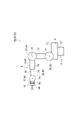
- the production system 1 (robot system) shown in FIG. 1 is a system for producing workpieces.
- work in the production process of the work, all the objects to be worked are referred to as "work".
- the "work” includes a final product in the production system 1, parts of the final product, a unit in which a plurality of parts are combined, and the like.
- the production system 1 includes one or more local devices 2 and a control system 3.
- the production system 1 includes a plurality of local devices 2 and produces a work by the cooperative operation of the plurality of local devices 2.
- Coordinated operation means that a plurality of local devices operate so as to share a plurality of steps for obtaining at least one final product.
- the plurality of local devices may operate so as to share a plurality of processes for obtaining one final product in a process unit, or a plurality of processes for obtaining a plurality of final products in a final product unit. It may operate so as to share with.
- Each of the plurality of local devices 2 is a device that directly executes work on the work 9 at the production site of the work 9.
- the direct work is, for example, the work of applying some energy such as thermal energy, kinetic energy, potential energy, etc. to the work 9.
- Each of the plurality of local devices 2 is, for example, an industrial device.
- the plurality of local devices 2 include at least a robot (at least one local device 2 is a robot). Further, the plurality of local devices 2 include industrial devices that cooperate with the robot. Specific examples of industrial equipment that cooperates with robots include NC machine tools and the like in addition to other robots.
- the plurality of local devices 2 shown in FIG. 1 include, but are not limited to, a transfer device 2A, robots 2B and 2C, and a mobile robot 2D. As long as it contains at least one robot, the number and type of local devices 2 can be changed as appropriate.
- the transport device 2A transports the work 9 using, for example, an electric motor or the like as a power source.
- the transfer device 2A include a belt conveyor, a roller conveyor, and the like.
- the robots 2B and 2C and the mobile robot 2D perform work on the work 9 transported by the transport device 2A.
- Specific examples of the work on the work 9 include assembling another work 9 (for example, a sub-part) to the work 9 (for example, a base part) conveyed by the transfer device 2A, and fastening the parts in the work 9 conveyed by the transfer device 2A. (For example, bolt fastening) / joining (for example, welding), loading of the work 9 into an NC machine tool installed around the transport device 2A, carrying out of the work 9 from the NC machine tool, and the like can be mentioned.
- the robots 2B and 2C are 6-axis vertical articulated robots, and as shown in FIG. 2, the base portion 11, the swivel portion 12, the first arm 13, the second arm 14, and the third arm 17 , The tip 18 and the actuators 41, 42, 43, 44, 45, 46.
- the base 11 is installed around the transport device 2A.
- the swivel portion 12 is provided on the base portion 11 so as to swivel around the vertical axis 21.
- the first arm 13 is connected to the swivel portion 12 so as to swing around the axis 22 intersecting (for example, orthogonal to) the axis 21.
- the intersection also includes a case where there is a twisting relationship such as a so-called grade separation.
- the second arm 14 is connected to the tip of the first arm 13 so as to swing around an axis 23 substantially parallel to the axis 22.
- the second arm 14 includes an arm base 15 and an arm end 16.
- the arm base 15 is connected to the tip of the first arm 13 and extends along an axis 24 that intersects (eg, is orthogonal to) the axis 23.
- the arm end 16 is connected to the tip of the arm base 15 so as to swivel around the axis 24.
- the third arm 17 is connected to the tip end portion of the arm end portion 16 so as to swing around the axis line 25 intersecting (for example, orthogonal to) the axis line 24.
- the tip 18 is connected to the tip of the third arm 17 so as to swivel around an axis 26 that intersects (eg, is orthogonal) the axis 25.
- a work tool such as a hand, a suction nozzle, or a welding torch is attached to the tip portion 18.
- the robots 2B and 2C have a joint 31 connecting the base 11 and the swivel portion 12, a joint 32 connecting the swivel portion 12 and the first arm 13, and the first arm 13 and the second arm 14. 33, a joint 34 connecting the arm base 15 and the arm end 16 in the second arm 14, a joint 35 connecting the arm end 16 and the third arm 17, and a third arm 17. It has a joint 36 that connects to the tip 18.
- the actuators 41, 42, 43, 44, 45, 46 include, for example, an electric motor and a speed reducer, and drive the joints 31, 32, 33, 34, 35, 36, respectively.
- the actuator 41 swings the swivel portion 12 around the axis 21, swings the first arm 13 around the axis 22, swings the second arm 14 around the axis 23, and swings the arm end 16 around the axis 24. Is swiveled, the third arm 17 is swung around the axis 25, and the tip portion 18 is swiveled around the axis 26.
- the robots 2B and 2C can be changed as appropriate.
- the robots 2B and 2C may be a 7-axis redundant robot in which a 1-axis joint is further added to the 6-axis vertical articulated robot, or may be a so-called scalar type articulated robot.
- the mobile robot 2D is a robot capable of autonomous traveling.
- the mobile robot 2D has a robot 10 configured in the same manner as the robots 2B and 2C, and an automatic guided vehicle 50.
- the automatic guided vehicle 50 autonomously travels so as to transport the robot 10.
- Specific examples of the automatic guided vehicle 50 include an electric so-called AGV (Automated Guided Vehicle).
- the production system 1 may further include an environment sensor 5.
- the environment sensor 5 detects the state of the working environment of the plurality of local devices 2 (hereinafter, referred to as “environmental state”). Specific examples of the environment sensor 5 include a camera that captures the working environment of a plurality of local devices 2.
- the environment sensor 5 may be a sensor that detects the presence or absence of the work 9 at a predetermined position by a laser beam or the like, or may be a sensor that detects the size or the like of the work 9.
- the production system 1 may include a plurality of environment sensors 5.
- the control system 3 controls a plurality of local devices 2.
- the configuration of the control system 3 will be illustrated in detail.
- the control system 3 operates a plurality of local devices 2 based on an operation program.
- the control system 3 has a plurality of local controllers 100, a host controller 200, and a data acquisition device 300.
- the plurality of local controllers 100 each control the plurality of local devices 2.
- each of the plurality of local controllers 100 controls the corresponding local device 2 based on a predetermined operation program.
- the plurality of local controllers 100 include a local controller 100A that controls the transfer device 2A, a local controller 100B that controls the robot 2B, a local controller 100C that controls the robot 2C, and a local controller 100D that controls the mobile robot 2D. including.
- the local controller 100A controls the transport device 2A so as to transport the work 9 based on a transport control operation program prepared in advance.
- the local controller 100B controls the actuators 41, 42, 43, 44, 45, 46 of the robot 2B so as to operate the robot 2B based on the operation program for robot control prepared in advance.
- the local controller 100C controls the actuators 41, 42, 43, 44, 45, 46 of the robot 2C so as to operate the robot 2C based on the operation program for robot control prepared in advance.
- the local controller 100D has the automatic guided vehicle 50 and the actuators 41, 42, 43, 44, 45, 46 of the robot 10 so as to operate the mobile robot 2D based on the operation program for robot control prepared in advance. And control.
- the host controller 200 acquires information indicating the operating state of the corresponding local device 2 (hereinafter referred to as “operation information”) from each of the plurality of local controllers 100, and detects the environmental state from the environment sensor 5 (hereinafter referred to as “operation information”). , "Environmental information”) is acquired, and an operation program execution command is output to each of the plurality of local controllers 100 based on the acquired operation information and environment information.
- the host controller 200 communicates synchronously with a plurality of local controllers 100. Synchronous communication means that communication with a plurality of local controllers 100 is repeatedly performed in a synchronous communication cycle synchronized with a synchronous frame having a fixed cycle.
- the host controller 200 acquires operation information from each of the plurality of local controllers 100, acquires environment information from the environment sensor 5, and executes the operation information to one of the plurality of local controllers 100 as necessary based on the operation information and the environment information. Outputting a command and repeatedly executing in synchronization with the synchronous communication cycle.
- the data collection device 300 collects various data acquired and generated during the control of the plurality of local devices 2 by the plurality of local controllers 100 and the host controller 200, and stores them in a database in a database format that can be analyzed later.
- the data accumulated by the data collection device 300 can be effectively used for productivity improvement or preventive maintenance in the production system 1.
- the data content to be stored in the database may change according to a change in the configuration of the production system 1, a change in the operation sequence of the production system 1, or the like.
- the data collection device 300 has one or more data collectors that collect RAW data in which one or more RAW records relating to the operation of industrial equipment are arranged for each one or more types, and one or more data collectors for each one or more types.
- the analysis data in which the analysis records are arranged is acquired, the analysis record of a predetermined type is extracted from the analysis data based on the data array of the analysis data, and the extracted analysis record is subjected to the predetermined analysis processing.
- a data analyzer that generates one or more result records and arranges one or more result records for each one or more types, and registration data that arranges one or more registration records for each one or more types.
- Data flow between the database accessor, the data collector, the data analyzer, and the database accessor that obtains and converts the registration data into a predetermined database format based on the data array of the registration data and registers it in the database. It is equipped with an application manager that controls the data.
- the contents registered in the database can be flexibly expanded while maintaining the database format. be able to. Therefore, it is effective in achieving both the ease of expanding the database and the ease of using the database.
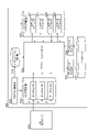
- the data collecting device 300 has a collector storage unit 310, an analyzer storage unit 320, a database accessor 331, a database 332, an application storage unit 333, and an application manager 334.
- the collector storage unit 310 stores one or more data collectors 311.
- the collector storage unit 310 stores a plurality of data collectors 311.
- Each of the plurality of data collectors 311 is a program library that collects RAW data in which one or more RAW records relating to the operation of one or more local devices 2 are arranged for each of one or more types.
- each of the plurality of data collectors 311 is a dynamic link library that can be dynamically combined with an executable program.
- the RAW record is a raw record that has not been processed by the data collection device 300.
- array structure data The data in which one or more records are arranged for each one or more types like the above-mentioned RAW data is referred to as "array structure data" in the following. According to the array structure data, it is possible to specify the type of the record by arranging the record in the data.
- the array structure data include comma-separated text data (CSV data), tab-delimited text data, and the like.
- CSV data one data set including a plurality of records corresponding to a plurality of types is stored separated by line breaks.
- each data set a plurality of records are arranged in a predetermined order of type, and the records are separated from each other by a comma.
- the type of each record can be specified by the position from the beginning in the corresponding data set.
- the array structure data may include attribute definition data that defines attributes for each of one or more types of one or more records.
- the attribute means a property common to records belonging to the same type. Specific examples of common properties include what physical quantity is expressed in what unit.
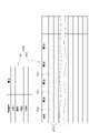
- FIG. 4 is a table illustrating the sequence structure data.
- the array structure data 410 includes a header 411 and recorded data 412.
- the recorded data 412 is data in which a plurality of records are arranged in association with time for each of a plurality of types.
- the recorded data 412 includes a multi-line data set 413.
- Each dataset 413 includes a time 415 and a plurality of records 414 corresponding to the plurality of types.
- Specific examples of the time 415 include acquisition times of a plurality of records 414.
- a plurality of records 414 are arranged in order of type from the left.
- the header 411 corresponds to the attribute definition data described above, and defines attributes for each of a plurality of series.
- the header 411 defines the attributes of the RAW record for each of a plurality of types.
- the attribute of the RAW record may be a control command for operating the local device 2 or a detected value of the operation result of the local device 2.
- Specific examples of RAW record attributes are shown below.
- Example 1-1) The amount of movement (for example, the movement angle) of the actuator (for example, actuators 41, 42, 43, 44, 45, 46) is represented by an angle [rad].
- the operating speed of the actuator is expressed by the angular velocity [rad / s].
- Example 1-3 The driving force generated by the actuator is expressed by torque [Nm].
- Example 1-4 Represents the drive current [A] of the actuator.
- Example 1-5) A control command for the local device 2 is given to the target coordinates (X [m], Y [m], Z [m]) and the target attitude ( ⁇ x [rad], ⁇ y [rad], in a predetermined coordinate system. It is represented by ⁇ z [rad]).
- Example 1-6) Represents the actuator control mode (position control mode / torque control mode).
- the attribute of the RAW record may be environmental information based on the detection result of the environment sensor 5.
- the plurality of data collectors 311 may each correspond to a plurality of local devices 2, or at least one of the plurality of data collectors 311 may correspond to two or more local devices 2. ..
- Each of the plurality of data collectors 311 may collect RAW data from, for example, the host controller 200, or may collect RAW data from the local controller 100 of the corresponding local device 2.
- RAW data from the host controller 200
- Each of the plurality of data collectors 311 may acquire the RAW data generated by the upper controller 200 or the local controller 100, and accumulates the RAW records collected from the upper controller 200 or the local controller 100 to generate the RAW data. May be good.
- the analyzer storage unit 320 stores one or more primary data analyzers 321.
- the analyzer storage unit 320 stores a plurality of primary data analyzers 321.
- Each of the plurality of primary data analyzers 321 acquires analysis data in which one or more analysis records are arranged for each one or more types, and based on the data arrangement of the analysis data, the analysis data is used for analysis of a predetermined type.
- a program library that extracts records, performs a predetermined primary analysis process on the extracted analysis records, generates one or more result records, and generates result data in which one or more result records are arranged for each one or more types.
- each of the plurality of primary data analyzers 321 is a dynamic link library that can be dynamically combined with an executable program.
- the result record is a processed record that has been processed by the data collection device 300.
- the analysis data is also array structure data in which one or more records are arranged for each one or more types.
- Each of the plurality of primary data analyzers 321 acquires the RAW data collected by any of the plurality of data collectors 311 as analysis data, and extracts the RAW record of a predetermined type as the analysis record from the RAW data.
- the RAW data includes the above-mentioned attribute definition data
- each of the plurality of primary data analyzers 321 may extract a predetermined type of RAW record based on the attribute definition data of the RAW data.
- the primary data analyzer 321 sets the RAW record whose value has changed with respect to the previous RAW record in chronological order. You may extract from a plurality of RAW records as the above result record.
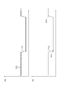
- FIG. 5A is a graph showing a time change of a RAW record represented by a binary value, as in the control mode of the actuator described above, and includes a plurality of RAW records R10.
- the transition TR10 of the control mode is represented by the plurality of RAW records R10.
- the primary data analyzer 321 extracts a RAW record whose value has changed with respect to the previous RAW record in chronological order as one or more result records from a plurality of RAW records, as shown in FIG. 5 (b).
- Two RAW records R11 and R12 will be extracted from the plurality of RAW records R10.
- the attribute "representing the change point of the control mode” it is possible to represent the transition TR10 of the control mode in the same manner as that represented by the plurality of RAW records R10. be.
- the amount of data required to represent the transition TR10 can be significantly reduced.
- Example 2-1 Based on the attribute definition data of RAW data, a RAW record indicating the operating speed of the actuator (hereinafter referred to as "speed record”) and a RAW record indicating the driving force of the actuator (hereinafter referred to as "force record”). ) And is extracted. Based on the relationship between the speed record and the force record, the degree of deterioration of the reducer of the actuator (an example of the result record) is generated. Result data is generated by adding a header that defines the attribute of one type as "deterioration degree of the reducer" to the recorded data arranged by associating one or more result records with one type.
- Example 2-2 Extract a RAW record (hereinafter referred to as "mode record") indicating the control mode of the actuator based on the attribute definition data of the RAW data.
- mode record a RAW record
- One or more mode records whose values have changed with respect to the previous mode record in chronological order are extracted from a plurality of mode records as result records.
- Result data is generated by adding a header that defines the attribute of one type as "representing the change point of the control mode" to the recorded data arranged by associating one or more result records with one type.
- the primary data analyzer 321 may generate result data in which one or more result records are arranged in association with time for each one or more types.
- the time in the result data may be the generation time of the result record or the acquisition time of the RAW record used for the generation of the result record.
- the database accessor 331 acquires registration data in which one or more registration records are arranged for each of one or more types, converts the registration data into a predetermined database format based on the data array of the registration data, and creates a database 332. It is a program library to be registered in. For example, the database accessor 331 is a dynamic link library that can be dynamically combined with an executable program.
- the registration data is also array structure data in which one or more records are arranged for each one or more types.
- the database format is, for example, a tag structure format in which structured tags are attached to individual records.
- Specific examples of the tag structure format include a JSON (Javascript Object Notation) format.
- FIG. 6 is a schematic diagram illustrating the tag structure data in which the sequence structure data is in the tag structure format.
- the tag structure data includes a plurality of structured records 420.
- Each of the plurality of structured records 420 includes a record value 422 and a structured tag 421 attached to the record value 422.
- the database accessor 331 may be registered in the database 332 by attaching a structured tag to each of one or more registration records based on the data array of the registration data.
- the database accessor 331 of one or more registration records is based on each type of one or more registration records and the attribute definition data of the registration data.
- a structured tag indicating an attribute may be attached to each.
- the database accessor 331 may attach a structured tag further indicating the arrangement within the type to each of one or more registration records. For example, when the registration data arranges a plurality of registration records for each of one or more types in association with the time, the database accessor 331 uses the time (arrangement within the type) for each of the plurality of registration records. A structured tag further indicating one example) may be attached.
- the database accessor 331 acquires the result data generated by any of the plurality of primary data analyzers 321 as registration data, converts the result data into a database format based on the data array of the result data, and registers the result data in the database 332. ..
- the database accessor 331 attaches a structured tag to each of one or more result records based on each type of one or more result records of the result data and the attribute definition data of the result data. For example, when the result data arranges a plurality of result records in association with the time with respect to the deterioration degree of the speed reducer, the database accessor 331 has an attribute "deterioration of the speed reducer" for each of the plurality of result records. A structured tag indicating "degree" and time is attached.
- the database accessor 331 further acquires the RAW data collected by any of the plurality of data collectors 311 as registration data, converts the RAW data into a database format based on the data array of the RAW data, and registers the RAW data in the database 332. May be good.
- the database accessor 331 may attach a structured tag to each of one or more RAW records based on each type of one or more RAW records of RAW data and the attribute definition data of RAW data. ..
- RAW data arranges a plurality of RAW records in relation to time for each of "actuator operating amount", “actuator operating speed”, “actuator driving force”, and "actuator driving current".
- the database accessor 331 attaches a structured tag indicating the attribute "actuator operation amount” and the time to each of the plurality of RAW records belonging to the "actuator operation amount”.
- the database accessor 331 attaches a structured tag indicating the attribute "actuator operating speed” and the time to each of the plurality of RAW records belonging to the "actuator operating speed”.
- the database accessor 331 attaches a structured tag indicating the attribute "driving force generated by the actuator” and the time to each of the plurality of RAW records belonging to the "driving force generated by the actuator”. Further, the database accessor 331 attaches a structured tag indicating the attribute "actuator drive current” and the time to each of the plurality of RAW records belonging to the "actuator drive current”.
- the application manager 334 controls the flow of data between the data collector 311, the primary data analyzer 321 and the application storage unit 333.
- the application manager 334 controls the transfer of sequence structure data between the data collector 311, the primary data analyzer 321 and the application storage unit 333 based on the application program stored in the application storage unit 333.
- Passing the sequence structure data includes storing the sequence structure data in a predetermined storage area and passing a reference to the storage area.
- the application program is, for example, an executable program.
- the application program may include the following processing.
- Process 1-1) One of the plurality of data collectors 311 is activated at a predetermined time, and the RAW data collected by the activated data collector 311 is stored in the first storage area.
- Process 1-2) As a storage area for analysis data, one of a plurality of primary data analyzers 321 is started while passing a reference to the first storage area, and the result record generated by the started primary data analyzer 321 is used as the second result record. Store in the storage area.
- Process 1-3) The database accessor 331 is started while passing the reference of the second storage area as the storage area of the registration data, and the started database accessor 331 converts the result data into the database format and registers it in the database 332. ..
- the application manager 334 causes the primary data analyzer 321 to acquire the RAW data collected by the data collector 311 as analysis data, and causes the database accessor 331 to acquire the result data generated by the primary data analyzer 321 as registration data. It becomes.
- the application program may further include the following processing.
- Process 2-1 The database accessor 331 is started while passing the reference of the first storage area as the storage area of the registration data, and the started database accessor 331 converts the RAW record into the database format and registers it in the database 332. ..
- the application manager 334 will have the database accessor 331 further acquire the RAW data collected by the data collector 311 as registration data.
- the application storage unit 333 is an example of a setting storage unit that stores the necessity setting for determining the necessity of registering the RAW data. Further, the application manager 334 switches whether or not to have the database accessor 331 acquire the RAW data as registration data based on the necessity setting of the setting storage unit.
- the application program may be configured to switch whether or not to execute process 2-1 based on one or more result records generated by the primary data analyzer 321.
- the application manager 334 switches whether or not to have the database accessor 331 acquire the RAW data as registration data based on one or more result records generated by the primary data analyzer 321.
- the application program requires processing 2-1 to be executed when an abnormality is found in one or more result records generated by the primary data analyzer 321 and an abnormality is found in one or more result records generated by the primary data analyzer 321. If is not recognized, the process 2-1 may be configured to be unnecessary to be executed.
- the data acquisition device 300 may further include a database accessor 335, and the analyzer storage unit 320 may further store one or more secondary data analyzers 322.
- the analyzer storage unit 320 may store a plurality of secondary data analyzers 322.
- the database accessor 335 (second database accessor) generates secondary data in which one or more secondary records are arranged for each one or more types based on the data read from the database 332.
- the secondary data is also array structure data in which one or more records are arranged for each one or more types.
- the database accessor 335 reads data including a plurality of structured records from the database 332, generates attribute definition data of array structure data based on the structured tags included in each structured record, and records included in each structured record. The values are arranged for each of one or more types based on the attribute definition data.
- Each of the plurality of secondary data analyzers 322 acquires the secondary analysis data in which one or more secondary analysis records are arranged for each of one or more types, and the data of the secondary analysis data.
- a predetermined type of secondary analysis record is extracted from the secondary analysis data based on the array, and the extracted secondary analysis record is subjected to a predetermined secondary analysis process (second analysis process) to perform one or more two. It is a program library that generates the next result record and generates the secondary result data in which one or more secondary result records are arranged for each one or more types.
- each of the plurality of secondary data analyzers 322 acquires the secondary data generated by the database accessor 335 as the secondary analysis data, and based on the data array of the secondary data, the secondary data of a predetermined type is obtained from the secondary data.
- the analysis records were extracted, the extracted secondary analysis records were subjected to secondary analysis processing to generate one or more secondary result records, and one or more secondary result records were arranged for each of one or more types. Generate secondary result data.
- Example 3-1 The database accessor 335 reads data including a plurality of structured tags having a time within a predetermined period and a structured tag indicating the above-mentioned "deterioration degree of the speed reducer" from the database 332.
- the database accessor 335 generates a secondary record including recorded data in which records of a plurality of structured tags read out are arranged in association with time, and attribute definition data in which the attribute of the type is "deterioration degree of the reducer". do.
- the secondary data analyzer 322 extracts a secondary analysis record indicating the degree of deterioration of the speed reducer from the secondary record.
- the secondary data analyzer 322 derives a maintenance recommended time when the deterioration degree of the speed reducer reaches a predetermined level as a secondary result record based on the secondary analysis record.
- the secondary data analyzer 322 adds a header that defines the attribute of one type as "recommended maintenance time of the reducer" to the recorded data arranged by associating one or more result records with one type. Generate result data.
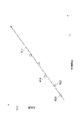
- FIG. 7 is a graph for schematically showing the derivation of the recommended maintenance time.
- the horizontal axis of FIG. 7 represents the elapsed time, and the vertical axis represents the degree of deterioration of the speed reducer.
- the secondary data analyzer 322 derives the deterioration tendency line TL1 based on the plurality of result records R20, and derives the elapsed time t1 at which the threshold value TV1 for recommending maintenance and the deterioration tendency line TL1 intersect as the maintenance recommended time. do.
- the application program may further include the following processing.
- Process 3-1) The database accessor 335 is started at a predetermined time, and the secondary data generated by the started database accessor 335 is stored in the third storage area.
- Process 3-2) As the storage area for the secondary analysis data, one of the plurality of secondary data analyzers 322 is started while passing the reference of the third storage area, and the secondary data analyzer 322 generated by the started secondary data analyzer 322 is started. The next result record is stored in the fourth storage area.
- Process 3-3) Start the database accessor 331 while passing the reference of the fourth storage area as the storage area of the registration data, and convert the secondary result data to the database format by the started database accessor 331 to the database 332. Let me register.
- the application manager 334 causes the secondary data analyzer 322 to acquire the secondary data generated by the database accessor 335 as the secondary analysis data, and the secondary result data generated by the secondary data analyzer 322 as the registration data. It will be acquired by the database accessor 331.
- the database accessor 331 further acquires the secondary result data, converts the secondary result data into a database format based on the data array of the secondary result data, and further registers the secondary result data in the database.
- the analyzer storage unit 320 may store the identification information of the secondary data analyzer 322 in association with the record type required for the secondary analysis process.
- the application manager 334 may specify a read target from the database 332 based on the record type associated with the secondary data analyzer 322 in the analyzer storage unit 320 and cause the database accessor 335 to generate the secondary data. good.
- the data collection device 300 may further have a program registration unit 336.
- the program registration unit 336 acquires a new application program created by the user and stores it in the application storage unit 333.
- the data collection device 300 holds the data collector 311, the primary data analyzer 321 and the secondary data analyzer 322, the database accessor 331, the database accessor 335, etc. used by the application program. Therefore, the application program can be created by a combination of the data collector 311, the primary data analyzer 321 and the secondary data analyzer 322, the database accessor 331, and the database accessor 335, and a simple task of defining the flow of the sequence structure data, the execution time, and the like. Can be created.
- the application program includes the necessity setting that determines the necessity of registration of RAW data. Therefore, the program registration unit 336 is an example of a setting acquisition unit that acquires the necessity setting for determining the necessity of registration of RAW data and stores it in the setting storage unit.
- the program registration unit 336 may be configured to further acquire the data collector 311 created by the user and store it in the collector storage unit 310.
- the data collector 311 can be added according to the addition of the local device 2 or the like, and the collected RAW data can be flexibly expanded.
- the program registration unit 336 may be configured to further acquire the primary data analyzer 321 or the secondary data analyzer 322 created by the user and store it in the analyzer storage unit 320. In this case, the contents of the primary analysis process and the secondary analysis process can be flexibly modified.
- FIG. 8 is a block diagram illustrating the hardware configuration of the control system 3.
- the local controller 100 has a circuit 190.
- the circuit 190 includes one or more processors 191 and a memory 192, a storage 193, a communication port 194, and a driver circuit 195.
- the storage 193 has a computer-readable storage medium, such as a non-volatile semiconductor memory.
- the storage 193 stores a control program for causing the local controller 100 to control the local device 2 based on the operation program.
- the memory 192 temporarily stores the program loaded from the storage medium of the storage 193 and the calculation result by the processor 191.
- the processor 191 constitutes each functional block of the local controller 100 by executing the above program in cooperation with the memory 192.
- the communication port 194 communicates with the host controller 200 via the first network line NW1 according to a command from the processor 191.
- the driver circuit 195 outputs drive power to the local device 2 according to a command from the processor 191.
- the host controller 200 has a circuit 290.
- Circuit 290 includes one or more processors 291 and memory 292, storage 293, communication ports 294, 295, and input / output ports 296.
- the storage 293 has a computer-readable storage medium, such as a non-volatile semiconductor memory.
- the storage 293 stores a program for causing the host controller 200 to acquire the operation information and the environment information and to output the execution command of the operation program based on the operation information and the environment information.
- the memory 292 temporarily stores the program loaded from the storage medium of the storage 293 and the calculation result by the processor 291.
- the processor 291 constitutes each functional block of the host controller 200 by executing the above program in cooperation with the memory 292.
- the communication port 294 communicates with the local controller 100 via the first network line NW1 according to a command from the processor 291.
- the communication port 295 communicates with the data acquisition device 300 via the second network line NW2 according to the command from the processor 291.
- the input / output port 296 inputs / outputs information to / from the environment sensor 5 according to a command from the processor 291.
- the data acquisition device 300 has a circuit 390.
- the circuit 390 includes one or more processors 391, a memory 392, a storage 393, a communication port 394, a display device 395, and an input device 396.
- the storage 393 has a computer-readable storage medium, such as a non-volatile semiconductor memory.
- the storage 393 data includes a collector storage unit 310, an analyzer storage unit 320, an application storage unit 333, a storage unit of the database accessor 331 and the database accessor 335, an application manager 334, and a program registration unit 336 as program storage units. It further includes a storage unit for a base program (eg, an operating system) to be configured in the collector 300. Further, the storage 393 includes a storage unit of the database 332.
- the memory 392 temporarily stores the program loaded from the storage medium of the storage 393 and the calculation result by the processor 391.
- the processor 391 constitutes each functional block of the data acquisition device 300 by executing the above program in cooperation with the memory 392.
- the communication port 394 communicates with the host controller 200 via the second network line NW2 according to a command from the processor 391.
- the display device 395 and the input device 396 function as a user interface of the data acquisition device 300.
- the display device 395 includes, for example, a liquid crystal monitor and is used for displaying information to the user.
- the input device 396 is, for example, a keypad or the like, and acquires input information by the user.
- the display device 395 and the input device 396 may be integrated like a so-called touch panel.
- the display device 395 and the input device 396 may be provided in an external device connected to the data collection device 300, or may be incorporated in the data collection device 300.
- circuits 190, 290, and 390 are not necessarily limited to those that configure each function by a program.
- the circuits 190, 290, and 390 may be configured with at least a part of functions by a dedicated logic circuit or an ASIC (Application Specific Integrated Circuit) that integrates the dedicated logic circuit.
- ASIC Application Specific Integrated Circuit
- This procedure collects RAW data in which one or more RAW records are arranged for each one or more types from industrial equipment, acquires RAW data, and analyzes a predetermined type from RAW data based on the data arrangement of the RAW data.
- To generate one or more result records by extracting the records for analysis and performing a predetermined analysis process on the extracted records for analysis, and to generate result data in which one or more result records are arranged for each one or more types. , Acquiring the result data, converting the result data into a predetermined database format based on the data array of the result data, and registering the result data in the database.
- the data collection procedure includes a program registration procedure, a primary analysis procedure, a RAW data registration procedure, and a secondary analysis procedure.
- a program registration procedure a primary analysis procedure
- a RAW data registration procedure a RAW data registration procedure
- a secondary analysis procedure a procedure that will be illustrated in detail.
- the data acquisition device 300 first executes steps S01 and S02.
- the program registration unit 336 causes the display device 395 to display the programming screen.
- the programming screen includes, for example, a combination of a data collector 311, a primary data analyzer 321 and a secondary data analyzer 322, a database accessor 331, and a database accessor 335, an application definition area that defines the flow of array structure data, an execution time, and the like.
- An application registration operation unit (for example, a button) that requests registration of an application program
- a collector registration operation unit for example, a button
- an analyzer registration that requests registration of a primary data analyzer or a secondary data analyzer.
- the program registration unit 336 confirms whether or not the application registration operation unit has requested the registration of the application program.
- step S02 If it is determined in step S02 that the registration of the application program is requested, the data acquisition device 300 executes steps S03 and S04.
- step S03 the program registration unit 336 generates an application program based on the input contents in the application definition area.
- step S04 the program registration unit 336 stores the application program in the application storage unit 333.
- step S02 If it is determined in step S02 that the registration of the application program is not requested, the data acquisition device executes step S05.
- step S05 the program registration unit 336 confirms whether or not the registration of the data collector 311 is requested by the collector registration operation unit.
- step S05 If it is determined in step S05 that the registration of the data collector 311 is requested, the data collection device executes steps S06, S07, S08.
- step S06 the program registration unit 336 causes the display device 395 to display a collector selection screen for selecting one or more new data collectors 311 generated in advance.
- step S07 the program registration unit 336 waits for the selection input on the collector selection screen.
- step S08 the program registration unit 336 stores one or more new data collectors 311 selected on the collector selection screen in the collector storage unit 310.
- step S05 If it is determined in step S05 that the registration of the data collector 311 is not requested, the data collection device 300 executes step S11.
- step S11 the program registration unit 336 confirms whether or not the analyzer registration operation unit has requested the registration of the primary data analyzer 321 or the secondary data analyzer 322.
- step S11 If it is determined in step S11 that registration of the primary data analyzer 321 or the secondary data analyzer 322 is requested, the data acquisition device 300 executes steps S12, S13, and S14.
- step S12 the program registration unit 336 causes the display device 395 to display an analyzer selection screen for selecting one or more new primary data analyzers 321 or secondary data analyzers 322 generated in advance.
- step S13 the program registration unit 336 waits for the selection input on the analyzer selection screen.
- step S14 the program registration unit 336 stores one or more new primary data analyzers 321 or secondary data analyzers 322 selected on the analyzer selection screen in the analyzer storage unit 320.
- the program registration unit 336 associates the identification information of the secondary data analyzer 322 with the record type required for the secondary analysis process, and associates the analyzer storage unit 320 with the record type. You may memorize it in.
- step S15 the data acquisition device 300 executes step S15.
- the data acquisition device 300 also executes step S15 when it is determined in step S11 that the registration of the primary data analyzer 321 and the secondary data analyzer 322 is not requested.
- step S15 the program registration unit 336 confirms whether or not the input for completing the programming has been made on the programming screen.
- step S15 If it is determined in step S15 that the input for completing programming has not been made, the data acquisition device 300 returns the process to step S02. If it is determined in step S15 that the input for completing the programming has been made, the program registration procedure is completed.
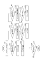
- FIG. 10 is a flowchart illustrating a procedure for executing any one of the primary analysis processes.
- one primary analysis process targeted by the flowchart of FIG. 10 is simply referred to as “primary analysis process”.
- the data acquisition device 300 first executes steps S21, S22, S23, S24, S25, S26, S27, and S28.
- step S21 the application manager 334 waits for the execution time of the primary analysis process.
- step S22 the application manager 334 activates one or more data collectors 311 for collecting RAW data necessary for the primary analysis process among the plurality of data collectors 311. Each of one or more activated data collectors 311 collects RAW data.
- step S23 the application manager 334 starts the primary data analyzer 321 for the primary analysis process using the RAW data collected in step S22 as the analysis data. The activated primary data analyzer 321 acquires the specified RAW data and extracts the primary analysis record from the RAW data.
- step S24 the primary data analyzer 321 performs primary analysis processing on the analysis records extracted in step S23 to generate one or more result records, and one or more result records are arranged for each of one or more types. Generate data.
- step S25 the application manager 334 starts the database accessor 331 using the result data generated in step S24 as registration data. The database accessor 331 acquires the specified result data and reads the first result record from the result data.
- step S26 the database accessor 331 attaches a structured tag to the result record based on the data array of the result data, and generates a structured record.
- step S27 the database accessor 331 stores the structured record in the database 332.
- step S28 the database accessor 331 confirms whether or not the registration of all the result records in the result data has been completed.
- step S28 If it is determined in step S28 that an unregistered result record remains in the result data, the data collection device 300 executes step S29. In step S29, the database accessor 331 reads the next result record from the result data. After that, the data acquisition device 300 returns the process to step S26. After that, reading, structuring, and registration of the result record are repeated until the registration of all the result records in the result data is completed.
- step S28 When it is determined in step S28 that the registration of all the result records in the result data is completed, the primary analysis procedure is completed.
- the data collection device 300 repeatedly executes the above processing.
- FIG. 11 is a flowchart illustrating a procedure for registering any one of the RAW data.
- RAW data one RAW data targeted by the flowchart of FIG. 11 is simply referred to as “RAW data”.
- the data acquisition device 300 first executes steps S31, S32, S33, S34, S35, and S36.
- step S31 the application manager 334 waits for the RAW data collection time.
- step S32 the application manager 334 activates the data collector 311 for collecting RAW data. Each of the activated data collectors 311 collects RAW data.
- step S33 the application manager 334 starts the database accessor 331 using the RAW data collected in step S32 as registration data.
- the database accessor 331 acquires the specified RAW data and reads the first RAW record from the RAW data.
- step S34 the database accessor 331 attaches a structured tag to the RAW record based on the data array of the RAW data, and generates a structured record.
- step S35 the database accessor 331 stores the structured record in the database 332.
- step S36 the database accessor 331 confirms whether or not the registration of all RAW records in the RAW data has been completed.
- step S36 If it is determined in step S36 that an unregistered RAW record remains in the RAW data, the data collection device 300 executes step S37.
- step S37 the database accessor 331 reads the next RAW record from the RAW data. After that, the data acquisition device 300 returns the process to step S34. After that, reading, structuring, and registration of the RAW record are repeated until the registration of all the RAW records in the RAW data is completed.
- step S36 If it is determined in step S36 that the registration of all RAW records in the RAW data has been completed, the RAW data registration procedure is completed.
- the data collection device 300 repeatedly executes the above processing.
- FIG. 12 is a flowchart illustrating a procedure for executing any one of the secondary analysis processes.
- one secondary analysis process targeted by the flowchart of FIG. 12 is simply referred to as “secondary analysis process”.
- the data acquisition device 300 first executes steps S41, S42, S43, S44, S45, S46, S47, and S48.
- step S41 the application manager 334 waits for the execution time of the secondary analysis process.
- step S42 the application manager 334 specifies a read target from the database 332 based on the record type required for the secondary analysis process, and causes the database accessor 335 to generate the secondary data.
- the application manager 334 specifies a read target from the database 332 in the analyzer storage unit 320 based on the record type associated with the secondary data analyzer 322 for the secondary analysis process.
- step S43 the application manager 334 starts the secondary data analyzer 322 for the secondary analysis process using the secondary data generated in step S42 as the secondary analysis data.
- the activated secondary data analyzer 322 acquires the specified secondary data and extracts the secondary analysis record from the secondary data.
- step S44 the secondary data analyzer 322 performs secondary analysis processing on the secondary analysis records extracted in step S43 to generate one or more secondary result records, and one or more for each of one or more types. Generate secondary result data with an array of secondary result records.
- step S45 the application manager 334 starts the database accessor 331 using the secondary result data generated in step S44 as registration data.
- the database accessor 331 acquires the specified secondary result data and reads the first secondary result record from the secondary result data.
- step S46 the database accessor 331 attaches a structured tag to the secondary result record based on the data array of the secondary result data, and generates a structured record.
- step S47 the database accessor 331 stores the structured record in the database 332.
- step S48 the database accessor 331 confirms whether or not the registration of all the secondary result records in the secondary result data has been completed.
- step S48 If it is determined in step S48 that an unregistered secondary result record remains in the secondary result data, the data collection device 300 executes step S49.
- step S49 the database accessor 331 reads the next secondary result record from the secondary result data. After that, the data acquisition device 300 returns the process to step S46. After that, reading, structuring, and registration of the secondary result record are repeated until the registration of all the secondary result records in the secondary result data is completed.
- step S48 If it is determined in step S48 that the registration of all the secondary result records in the secondary result data has been completed, the secondary analysis procedure is completed.
- the data collection device 300 repeatedly executes the above processing.
- the application manager 334 may switch whether or not to have the database accessor 331 acquire the RAW data as registration data based on one or more result records generated by the primary data analyzer 321.
- the procedure for registering RAW data in this case is illustrated.
- the data acquisition device 300 first executes steps S51 to S59, which are the same primary analysis procedures as in steps S21 to S29. After that, the data acquisition device 300 executes step S61.
- the application manager 334 confirms whether or not the RAW data needs to be registered based on one or more result records generated by the primary data analyzer 321 in the primary analysis process.
- step S61 When it is determined in step S61 that RAW data registration is necessary, the data acquisition device 300 executes steps S63 to S67, which are the same RAW data registration procedures as steps S33 to S37. When it is determined in step S61 that the registration of the RAW data is unnecessary, the data acquisition device 300 omits the registration of the RAW data. This completes the RAW data registration procedure.
- the data collection device 300 has one or more data collectors 311 for collecting RAW data in which one or more RAW records relating to the operation of industrial equipment are arranged for each one or more types, and one or more types.
- Acquire analysis data in which one or more analysis records are arranged, extract a predetermined type of analysis record from the analysis data based on the data array of the analysis data, and perform a predetermined analysis on the extracted analysis record.
- a primary data analyzer 321 that performs processing to generate one or more result records and generates result data in which one or more result records are arranged for each one or more types, and one or more registration records for each one or more types.
- the database accessor 331, the data collector 311 and the primary data analyzer 321 that acquire the registration data in which the data is arranged, convert the registration data into a predetermined database format based on the data array of the registration data, and register the registration data in the database 332.
- an application manager 334 that controls the flow of data to and from the database accessor 331.
- the data collection device 300 At least one of the data collector 311 and the primary data analyzer 321 is added, and the data flow is changed by the application manager 334, so that the database format is maintained and the data is registered in the database 332.
- the content can be expanded flexibly. Therefore, it is effective to achieve both the ease of expanding the database 332 and the ease of using the database 332.
- the database format is a tag structure format in which individual records are tagged with a structure, and the database accessor 331 attaches a structured tag to each of one or more registration records based on the data array of registration data. It may be registered in the database 332. In this case, the ease of use of the database 332 is further improved by registering the data in the tag structure format.
- the registration data includes attribute definition data that defines attributes for each type of one or more registration records, and the database accessor 331 contains each type of one or more registration records and the attributes of the registration data.
- a structured tag indicating an attribute may be attached to each of one or more registration records based on the definition data. In this case, more appropriate structured tags can be easily attached to individual records.
- the database accessor 331 may attach a structured tag further indicating the arrangement within the type to each of one or more registration records. In this case, more appropriate structured tags can be easily attached to individual records.
- the application manager 334 may have the primary data analyzer 321 acquire the RAW data collected by the data collector 311 as analysis data, and the database accessor 331 may acquire the result data generated by the primary data analyzer 321 as registration data. In this case, the processing load on the database 332 can be reduced as compared with the case where the data once registered in the database 332 is read out and the analysis process is performed.
- the RAW data includes attribute definition data that defines attributes for each type of one or more RAW records, and the primary data analyzer 321 extracts a predetermined type of analysis record based on the attribute definition data of the RAW data. You may. In this case, the record for analysis can be easily extracted.
- the application manager 334 may further acquire the RAW data collected by the data collector 311 as registration data in the database accessor 331. In this case, by registering the RAW data in the database 332 in addition to the result data, it is possible to construct the database 332 that can be flexibly adapted to various needs that may occur in the future.
- the data collection device 300 further includes a program registration unit 336 (setting acquisition unit) that acquires the necessity setting that determines the necessity of registration of RAW data and stores it in the application storage unit 333 (setting storage unit), and the application manager 334 , Whether or not to have the database accessor 331 acquire the RAW data collected by the data collector 311 as registration data may be switched based on the necessity setting of the setting storage unit. In this case, the processing load on the database 332 can be further reduced by omitting the database registration of the RAW data that is not required by the user.
- the application manager 334 may switch whether or not to have the database accessor 331 acquire the RAW data collected by the data collector 311 as registration data based on one or more result records generated by the primary data analyzer 321. In this case, a more appropriate choice of RAW data can be supported.
- the data collection device 300 has a database accessor 335 that generates secondary data in which one or more secondary records are arranged for each one or more types based on the data read from the database 332, and one or more for each one or more types.
- the secondary analysis data in which the secondary analysis records are arranged is acquired, and the secondary analysis record of a predetermined type is extracted from the secondary analysis data based on the data array of the secondary analysis data.
- the application manager 334 causes the secondary data analyzer 322 to acquire the secondary data generated by the database accessor 335 as secondary analysis data, and the secondary data analyzer 322 generates the secondary data.
- the result data may be acquired by the database accessor 331 as registration data. In this case, it is possible to perform multi-step data analysis according to the accumulation status of data in the database 332, and it is possible to promote further effective utilization of the database 332.
- the data collection device 300 further includes an analyzer storage unit 320 that stores the identification information of the secondary data analyzer 322 in association with the record type required for the second analysis process, and the application manager 334 in the analyzer storage unit 320.
- the database accessor 335 may generate the secondary data by designating the read target from the database 332 based on the record type associated with the secondary data analyzer 322. In this case, the processing load on the database 332 can be further reduced by narrowing down the records to be read from the database 332 according to the contents of the secondary analysis.
- the data collector 311 collects RAW data in which a plurality of RAW records are arranged in association with time for each of one or more types, and the primary data analyzer 321 changes the value with respect to the previous RAW record in chronological order.
- the resulting RAW record may be extracted from a plurality of RAW records as one or more result records. In this case, it is possible to easily reduce the processing load on the database 332 while suppressing a decrease in the amount of information included in the plurality of RAW records.
- 2 ... Local equipment (industrial equipment), 300 ... Data collection device, 311 ... Data collector, 320 ... Analyzer storage, 321 ... Primary data analyzer (data analyzer), 322 ... Secondary data analyzer (second data analyzer), 331 ... Database accessor, 332 ... Database, 333 ... Application storage unit (setting storage unit), 334 ... Application manager, 335 ... Database accessor (second database accessor), 336 ... Program registration unit (setting acquisition unit).
Landscapes
- Engineering & Computer Science (AREA)
- Theoretical Computer Science (AREA)
- Databases & Information Systems (AREA)
- General Physics & Mathematics (AREA)
- Physics & Mathematics (AREA)
- General Engineering & Computer Science (AREA)
- Data Mining & Analysis (AREA)
- Automation & Control Theory (AREA)
- Software Systems (AREA)
- Quality & Reliability (AREA)
- Manufacturing & Machinery (AREA)
- Information Retrieval, Db Structures And Fs Structures Therefor (AREA)
- Testing And Monitoring For Control Systems (AREA)
- General Factory Administration (AREA)
- Automatic Analysis And Handling Materials Therefor (AREA)
Abstract
Description
図1に示す生産システム1(ロボットシステム)は、ワークの生産を行うシステムである。以下、ワークの生産過程において、作業対象となる物体の全てを「ワーク」という。例えば「ワーク」は、生産システム1における最終生産物、最終生産物の部品、及び複数の部品を組み合わせたユニット等を含む。
第1アーム13は、軸線21に交差(例えば直交)する軸線22まわりに揺動するように旋回部12に接続されている。交差は、所謂立体交差のようにねじれの関係にある場合も含む。第2アーム14は、軸線22に実質的に平行な軸線23まわりに揺動するように第1アーム13の先端部に接続されている。第2アーム14は、アーム基部15とアーム端部16とを含む。アーム基部15は、第1アーム13の先端部に接続され、軸線23に交差(例えば直交)する軸線24に沿って延びている。アーム端部16は、軸線24まわりに旋回するようにアーム基部15の先端部に接続されている。第3アーム17は、軸線24に交差(例えば直交)する軸線25まわりに揺動するようにアーム端部16の先端部に接続されている。先端部18は、軸線25に交差(例えば直交)する軸線26まわりに旋回するように第3アーム17の先端部に接続されている。先端部18には、例えはハンド、吸着ノズル、溶接トーチ等の作業ツールが取り付けられる。
例えばアクチュエータ41は、軸線21まわりに旋回部12を旋回させ、軸線22まわりに第1アーム13を揺動させ、軸線23まわりに第2アーム14を揺動させ、軸線24まわりにアーム端部16を旋回させ、軸線25まわりに第3アーム17を揺動させ、軸線26まわりに先端部18を旋回させる。
制御システム3は、複数のローカル機器2を動作プログラムに基づいて動作させる。制御システム3は、複数のローカルコントローラ100と、上位コントローラ200と、データ収集装置300とを有する。複数のローカルコントローラ100は、複数のローカル機器2をそれぞれ制御する。例えば、複数のローカルコントローラ100のそれぞれは、予め定められた動作プログラムに基づいて対応するローカル機器2を制御する。例えば複数のローカルコントローラ100は、搬送装置2Aを制御するローカルコントローラ100Aと、ロボット2Bを制御するローカルコントローラ100Bと、ロボット2Cを制御するローカルコントローラ100Cと、移動型ロボット2Dを制御するローカルコントローラ100Dとを含む。
例1-1)アクチュエータ(例えばアクチュエータ41,42,43,44,45,46)の動作量(例えば動作角度)を角度[rad]で表す。
例1-2)アクチュエータの動作速度を角速度[rad/s]で表す。
例1-3)アクチュエータが生じる駆動力をトルク[N・m]で表す。
例1-4)アクチュエータの駆動電流[A]を表す。
例1-5)ローカル機器2に対する制御指令を、所定の座標系における目標座標(X[m]、Y[m]、Z[m])及び目標姿勢(θx[rad]、θy[rad]、θz[rad])で表す。
例1-6)アクチュエータの制御モード(位置制御モード/トルク制御モード)を表す。
例2-1) RAWデータの属性定義データに基づいて、アクチュエータの動作速度を示すRAWレコード(以下、「速度レコード」という。)と、アクチュエータの駆動力を示すRAWレコード(以下、「力レコード」という。)とを抽出する。速度レコードと力レコードとの関係に基づいて、アクチュエータの減速機の劣化度(リザルトレコードの一例)を生成する。一つの種別に対し1以上のリザルトレコードを対応付けて配列した記録データに、一つの種別の属性を「減速機の劣化度」と定義するヘッダーを付与したリザルトデータを生成する。
例2-2) RAWデータの属性定義データに基づいて、アクチュエータの制御モードを示すRAWレコード(以下、「モードレコード」という。)を抽出する。時刻順における一つ前のモードレコードに対し値が変化した1以上のモードレコードをリザルトレコードとして複数のモードレコードから抽出する。一つの種別に対し1以上のリザルトレコードを対応付けて配列した記録データに、一つの種別の属性を「制御モードの変化点を表す」と定義するヘッダーを付与したリザルトデータを生成する。
また、データベースアクセサ331は、「アクチュエータの動作速度」に属する複数のRAWレコードのそれぞれに、属性である「アクチュエータの動作速度」と、時刻とを示す構造化タグを付す。
処理1-1)所定時期に複数のデータコレクタ311のいずれかを起動し、起動したデータコレクタ311が収集したRAWデータを第1記憶領域に記憶させる。
処理1-2)解析用データの記憶領域として、第1記憶領域の参照を引き渡しつつ、複数の一次データアナライザ321のいずれかを起動し、起動した一次データアナライザ321が生成したリザルトレコードを第2記憶領域に記憶させる。
処理1-3)登録用データの記憶領域として、第2記憶領域の参照を引き渡しつつ、データベースアクセサ331を起動し、起動したデータベースアクセサ331によってリザルトデータをデータベース形式に変換してデータベース332に登録させる。
処理2-1)登録用データの記憶領域として、第1記憶領域の参照を引き渡しつつ、データベースアクセサ331を起動し、起動したデータベースアクセサ331によってRAWレコードをデータベース形式に変換してデータベース332に登録させる。
例3-1)データベースアクセサ335は、所定期間内の時刻と、上述の「減速機の劣化度」とを示す構造化タグが付与された複数の構造化タグを含むデータをデータベース332から読み出す。データベースアクセサ335は、読み出した複数の構造化タグのレコードを時刻に対応付けて配列した記録データと、種別の属性を「減速機の劣化度」とする属性定義データとを含む二次レコードを生成する。二次データアナライザ322は、二次レコードから、減速機の劣化度を示す二次解析用レコードを抽出する。二次データアナライザ322は、二次解析用レコードに基づいて、減速機の劣化度が所定レベルに達するメンテナンス推奨時期を二次リザルトレコードとして導出する。二次データアナライザ322は、一つの種別に対し1以上のリザルトレコードを対応付けて配列した記録データに、一つの種別の属性を「減速機のメンテナンス推奨時期」と定義するヘッダーを付与した二次リザルトデータを生成する。
処理3-1)所定時期にデータベースアクセサ335を起動し、起動したデータベースアクセサ335が生成した二次データを第3記憶領域に記憶させる。
処理3-2)二次解析用データの記憶領域として、第3記憶領域の参照を引き渡しつつ、複数の二次データアナライザ322のいずれかを起動し、起動した二次データアナライザ322が生成した二次リザルトレコードを第4記憶領域に記憶させる。
処理3-3)登録用データの記憶領域として、第4記憶領域の参照を引き渡しつつ、データベースアクセサ331を起動し、起動したデータベースアクセサ331によって二次リザルトデータをデータベース形式に変換してデータベース332に登録させる。
続いて、データ収集方法の一例として、データ収集装置300が実行するデータ収集手順を詳細に例示する。この手順は、1以上の種別ごとに1以上のRAWレコードを配列したRAWデータを産業機器から収集することと、RAWデータを取得し、RAWデータのデータ配列に基づいてRAWデータから所定種別の解析用レコードを抽出し、抽出した解析用レコードに対し所定の解析処理を行って1以上のリザルトレコードを生成し、1以上の種別ごとに1以上のリザルトレコードを配列したリザルトデータを生成することと、リザルトデータを取得し、リザルトデータのデータ配列に基づいてリザルトデータを所定のデータベース形式に変換し、データベースに登録することと、を含む。
図9に示すように、データ収集装置300は、まずステップS01,S02を実行する。ステップS01では、プログラム登録部336が、プログラミング画面を表示デバイス395に表示させる。プログラミング画面は、例えば、データコレクタ311、一次データアナライザ321、二次データアナライザ322、データベースアクセサ331、データベースアクセサ335の組み合わせと、配列構造データの流れと、実行時期等を定義するアプリケーション定義領域と、アプリケーションプログラムの登録を要求するアプリケーション登録操作部(例えばボタン)と、データコレクタ311の登録を要求するコレクタ登録操作部(例えばボタン)と、一次データアナライザ又は二次データアナライザの登録を要求するアナライザ登録操作部(例えばボタン)とを含む。ステップS02では、アプリケーション登録操作部により、アプリケーションプログラムの登録が要求されたか否かをプログラム登録部336が確認する。
上述の説明から明らかであるように、データ収集装置300は複数種類の一次解析処理を実行し得る。図10は、いずれか一つの一次解析処理を実行する手順を例示するフローチャートである。以下においては、複数種類の一次解析処理のうち、図10のフローチャートが対象とする一つの一次解析処理を単に「一次解析処理」という。
上述の説明から明らかであるように、データ収集装置300は複数種類のRAWデータを取得し得る。図11は、いずれか一つのRAWデータを登録する手順を例示するフローチャートである。以下においては、複数種類のRAWデータのうち、図11のフローチャートが対象とする一つのRAWデータを単に「RAWデータ」という。
上述の説明から明らかであるように、データ収集装置300は複数種類の二次解析処理を実行し得る。図12は、いずれか一つの二次解析処理を実行する手順を例示するフローチャートである。以下においては、複数種類の二次解析処理のうち、図12のフローチャートが対象とする一つの二次解析処理を単に「二次解析処理」という。
上述したように、アプリケーションマネジャ334は、RAWデータを登録用データとしてデータベースアクセサ331に取得させるか否かを、一次データアナライザ321が生成した1以上のリザルトレコードに基づいて切り替えてもよい。この場合のRAWデータの登録手順を例示する。
以上に説明したように、データ収集装置300は、産業機器の動作に関する1以上のRAWレコードを1以上の種別ごとに配列したRAWデータを収集する1以上のデータコレクタ311と、1以上の種別ごとに1以上の解析用レコードを配列した解析用データを取得し、解析用データのデータ配列に基づいて解析用データから所定種別の解析用レコードを抽出し、抽出した解析用レコードに対し所定の解析処理を行って1以上のリザルトレコードを生成し、1以上の種別ごとに1以上のリザルトレコードを配列したリザルトデータを生成する一次データアナライザ321と、1以上の種別ごとに1以上の登録用レコードを配列した登録用データを取得し、登録用データのデータ配列に基づいて登録用データを所定のデータベース形式に変換し、データベース332に登録するデータベースアクセサ331と、データコレクタ311と、一次データアナライザ321と、データベースアクセサ331との間におけるデータの流れを制御するアプリケーションマネジャ334と、を備える。
Claims (18)
- 産業機器の動作に関する1以上のRAWレコードを1以上の種別ごとに配列したRAWデータを収集する1以上のデータコレクタと、
1以上の種別ごとに1以上の解析用レコードを配列した解析用データを取得し、前記解析用データのデータ配列に基づいて前記解析用データから所定種別の解析用レコードを抽出し、抽出した解析用レコードに対し所定の解析処理を行って1以上のリザルトレコードを生成し、1以上の種別ごとに1以上のリザルトレコードを配列したリザルトデータを生成するデータアナライザと、
1以上の種別ごとに1以上の登録用レコードを配列した登録用データを取得し、前記登録用データのデータ配列に基づいて前記登録用データを所定のデータベース形式に変換し、データベースに登録するデータベースアクセサと、
前記データコレクタと、前記データアナライザと、前記データベースアクセサとの間におけるデータの流れを制御するアプリケーションマネジャと、を備えるデータ収集装置。 - 前記データベース形式は、個々のレコードに構造化タグが付されたタグ構造形式であり、
前記データベースアクセサは、前記登録用データのデータ配列に基づいて前記1以上の登録用レコードのそれぞれに構造化タグを付して前記データベースに登録する、請求項1記載のデータ収集装置。 - 前記登録用データは、前記1以上の登録用レコードの前記1以上の種別ごとに属性を定義する属性定義データを含み、
前記データベースアクセサは、前記1以上の登録用レコードのそれぞれの種別と、前記登録用データの前記属性定義データとに基づいて、前記1以上の登録用レコードのそれぞれに属性を示す構造化タグを付す、請求項2記載のデータ収集装置。 - 前記データベースアクセサは、前記1以上の登録用レコードのそれぞれに対し、種別内における配置を更に示す構造化タグを付す、請求項3記載のデータ収集装置。
- 前記アプリケーションマネジャは、前記データコレクタが収集した前記RAWデータを前記解析用データとして前記データアナライザに取得させ、前記データアナライザが生成した前記リザルトデータを前記登録用データとして前記データベースアクセサに取得させる、請求項1~4のいずれか一項記載のデータ収集装置。
- 前記RAWデータは、前記1以上のRAWレコードの1以上の種別ごとに属性を定義する属性定義データを含み、
前記データアナライザは、前記RAWデータの前記属性定義データに基づいて前記所定種別の解析用レコードを抽出する、請求項5記載のデータ収集装置。 - 前記アプリケーションマネジャは、前記データコレクタが収集した前記RAWデータを前記登録用データとして前記データベースアクセサに更に取得させる、請求項5又は6記載のデータ収集装置。
- 前記RAWデータの登録要否を定める要否設定を取得して設定記憶部に記憶させる設定取得部を更に備え、
前記アプリケーションマネジャは、前記データコレクタが収集した前記RAWデータを前記登録用データとして前記データベースアクセサに取得させるか否かを前記設定記憶部の前記要否設定に基づいて切り替える、請求項7記載のデータ収集装置。 - 前記アプリケーションマネジャは、前記データコレクタが収集した前記RAWデータを前記登録用データとして前記データベースアクセサに取得させるか否かを、前記データアナライザが生成した前記1以上のリザルトレコードに基づいて切り替える、請求項7記載のデータ収集装置。
- 前記データベースから読み出したデータに基づいて、1以上の種別ごとに1以上の二次レコードを配列した二次データを生成する第2データベースアクセサと、
1以上の種別ごとに1以上の二次解析用レコードを配列した二次解析用データを取得し、前記二次解析用データのデータ配列に基づいて前記二次解析用データから所定種別の二次解析用レコードを抽出し、抽出した二次解析用レコードに対し所定の第2解析処理を行って1以上の二次リザルトレコードを生成し、1以上の種別ごとに1以上の二次リザルトレコードを配列した二次リザルトデータを生成する第2データアナライザと、を更に備え、
前記アプリケーションマネジャは、前記第2データベースアクセサが生成した前記二次データを前記二次解析用データとして前記第2データアナライザに取得させ、前記第2データアナライザが生成した前記二次リザルトデータを前記登録用データとして前記データベースアクセサに取得させる、請求項5~9のいずれか一項記載のデータ収集装置。 - 前記第2データアナライザの識別情報と、前記第2解析処理に必要なレコード種別とを対応付けて記憶するアナライザ記憶部を更に備え、
前記アプリケーションマネジャは、前記アナライザ記憶部において前記第2データアナライザに対応付けられた前記レコード種別に基づいて前記データベースからの読み出し対象を指定して前記第2データベースアクセサに前記二次データを生成させる、請求項10記載のデータ収集装置。 - 前記データコレクタは、1以上の種別ごとに、複数のRAWレコードを時刻に対応付けて配列した前記RAWデータを収集し、
前記データアナライザは、時刻順における一つ前のRAWレコードに対し値が変化したRAWレコードを前記1以上のリザルトレコードとして前記複数のRAWレコードから抽出する、請求項5~11のいずれか一項記載のデータ収集装置。 - 産業機器の動作に関する1以上のRAWレコードを1以上の種別ごとに配列したRAWデータを産業機器から収集する1以上のデータコレクタと、
前記RAWデータを取得し、前記RAWデータのデータ配列に基づいて前記RAWデータから所定種別の解析用レコードを抽出し、抽出した解析用レコードに対し所定の解析処理を行って1以上のリザルトレコードを生成し、1以上の種別ごとに1以上のリザルトレコードを配列したリザルトデータを生成するデータアナライザと、
前記リザルトデータを取得し、前記リザルトデータのデータ配列に基づいて前記リザルトデータを所定のデータベース形式に変換し、データベースに登録するデータベースアクセサと、を備えるデータ収集装置。 - 前記データベース形式は、個々のレコードに構造化タグが付されたタグ構造形式であり、
前記データベースアクセサは、前記リザルトデータのデータ配列に基づいて前記1以上のリザルトレコードのそれぞれに構造化タグを付して前記データベースに登録する、請求項13記載のデータ収集装置。 - 前記データベースアクセサは、前記RAWデータを更に取得し、前記RAWデータのデータ配列に基づいて前記RAWデータを前記データベース形式に変換し、前記データベースに更に登録する、請求項13又は14記載のデータ収集装置。
- 前記データベースから読み出したデータに基づいて、1以上の種別ごとに1以上の二次レコードを配列した二次データを生成する第2データベースアクセサと、
前記二次データを取得し、前記二次データのデータ配列に基づいて前記二次データから所定種別の二次解析用レコードを抽出し、抽出した二次解析用レコードに対し所定の第2解析処理を行って1以上の二次リザルトレコードを生成し、1以上の種別ごとに1以上の二次リザルトレコードを配列した二次リザルトデータを生成する第2データアナライザと、を更に備え、
前記データベースアクセサは、前記二次リザルトデータを更に取得し、前記二次リザルトデータのデータ配列に基づいて前記二次リザルトデータを前記データベース形式に変換し、前記データベースに更に登録する、請求項13~15のいずれか一項記載のデータ収集装置。 - 産業機器の動作に関する1以上のRAWレコードを1以上の種別ごとに配列したRAWデータを収集する1以上のデータコレクタと、
1以上の種別ごとに1以上の解析用レコードを配列した解析用データを取得し、前記解析用データのデータ配列に基づいて前記解析用データから所定種別の解析用レコードを抽出し、抽出した解析用レコードに対し所定の解析処理を行って1以上のリザルトレコードを生成し、1以上の種別ごとに1以上のリザルトレコードを配列したリザルトデータを生成するデータアナライザと、
1以上の種別ごとに1以上の登録用レコードを配列した登録用データを取得し、前記登録用データのデータ配列に基づいて前記登録用データを所定のデータベース形式に変換し、データベースに登録するデータベースアクセサと、
前記データコレクタと、前記データアナライザと、データベースアクセサとの間におけるデータの流れを制御するアプリケーションマネジャと、を備えるプログラム。 - 産業機器の動作に関する1以上のRAWレコードを1以上の種別ごとに配列したRAWデータを産業機器から収集することと、
前記RAWデータを取得し、前記RAWデータのデータ配列に基づいて前記RAWデータから所定種別の解析用レコードを抽出し、抽出した解析用レコードに対し所定の解析処理を行って1以上のリザルトレコードを生成し、1以上の種別ごとに1以上のリザルトレコードを配列したリザルトデータを生成することと、
前記リザルトデータを取得し、前記リザルトデータのデータ配列に基づいて前記リザルトデータを所定のデータベース形式に変換し、データベースに登録することと、を含むデータ収集方法。
Priority Applications (4)
| Application Number | Priority Date | Filing Date | Title |
|---|---|---|---|
| CN202080106767.6A CN116507983B (zh) | 2020-10-29 | 2020-10-29 | 数据采集装置、程序以及数据采集方法 |
| JP2022558718A JP7559080B2 (ja) | 2020-10-29 | 2020-10-29 | データ収集装置、プログラム及びデータ収集方法 |
| PCT/JP2020/040673 WO2022091306A1 (ja) | 2020-10-29 | 2020-10-29 | データ収集装置、プログラム及びデータ収集方法 |
| US18/306,246 US12229157B2 (en) | 2020-10-29 | 2023-04-25 | Data collection from industrial equipment |
Applications Claiming Priority (1)
| Application Number | Priority Date | Filing Date | Title |
|---|---|---|---|
| PCT/JP2020/040673 WO2022091306A1 (ja) | 2020-10-29 | 2020-10-29 | データ収集装置、プログラム及びデータ収集方法 |
Related Child Applications (1)
| Application Number | Title | Priority Date | Filing Date |
|---|---|---|---|
| US18/306,246 Continuation US12229157B2 (en) | 2020-10-29 | 2023-04-25 | Data collection from industrial equipment |
Publications (1)
| Publication Number | Publication Date |
|---|---|
| WO2022091306A1 true WO2022091306A1 (ja) | 2022-05-05 |
Family
ID=81382095
Family Applications (1)
| Application Number | Title | Priority Date | Filing Date |
|---|---|---|---|
| PCT/JP2020/040673 Ceased WO2022091306A1 (ja) | 2020-10-29 | 2020-10-29 | データ収集装置、プログラム及びデータ収集方法 |
Country Status (4)
| Country | Link |
|---|---|
| US (1) | US12229157B2 (ja) |
| JP (1) | JP7559080B2 (ja) |
| CN (1) | CN116507983B (ja) |
| WO (1) | WO2022091306A1 (ja) |
Citations (2)
| Publication number | Priority date | Publication date | Assignee | Title |
|---|---|---|---|---|
| WO2017216830A1 (ja) * | 2016-06-13 | 2017-12-21 | 株式会社日立製作所 | データ解析システム |
| JP2018055457A (ja) * | 2016-09-29 | 2018-04-05 | 三菱電機株式会社 | データ収集システム、収集装置、情報収集プログラム、サーバ装置およびサーバプログラム |
Family Cites Families (6)
| Publication number | Priority date | Publication date | Assignee | Title |
|---|---|---|---|---|
| JP2002108903A (ja) * | 2000-09-29 | 2002-04-12 | Toshiba Corp | データ収集システムおよびデータ収集方法およびプログラムを記録した媒体およびプログラム製品 |
| WO2005006105A2 (de) * | 2003-07-09 | 2005-01-20 | Hillinger Schmiedl Gadermayr | Datenerfassungs- und datenverarbeitungssystem |
| JP5783739B2 (ja) * | 2011-02-08 | 2015-09-24 | キヤノン株式会社 | 撮像装置及びシステム |
| JP5672336B2 (ja) * | 2013-05-28 | 2015-02-18 | オムロン株式会社 | データ収集装置、並びに、該データ収集装置の制御方法および制御プログラム |
| JP2016194808A (ja) * | 2015-03-31 | 2016-11-17 | オムロン株式会社 | プログラマブルロジックコントローラ、データ収集装置、データベースアクセス方法およびデータベースアクセスプログラム |
| CN111538590A (zh) * | 2020-04-17 | 2020-08-14 | 姜海强 | 一种基于cs架构的分布式数据采集方法及系统 |
-
2020
- 2020-10-29 JP JP2022558718A patent/JP7559080B2/ja active Active
- 2020-10-29 WO PCT/JP2020/040673 patent/WO2022091306A1/ja not_active Ceased
- 2020-10-29 CN CN202080106767.6A patent/CN116507983B/zh active Active
-
2023
- 2023-04-25 US US18/306,246 patent/US12229157B2/en active Active
Patent Citations (2)
| Publication number | Priority date | Publication date | Assignee | Title |
|---|---|---|---|---|
| WO2017216830A1 (ja) * | 2016-06-13 | 2017-12-21 | 株式会社日立製作所 | データ解析システム |
| JP2018055457A (ja) * | 2016-09-29 | 2018-04-05 | 三菱電機株式会社 | データ収集システム、収集装置、情報収集プログラム、サーバ装置およびサーバプログラム |
Also Published As
| Publication number | Publication date |
|---|---|
| JP7559080B2 (ja) | 2024-10-01 |
| US12229157B2 (en) | 2025-02-18 |
| JPWO2022091306A1 (ja) | 2022-05-05 |
| CN116507983B (zh) | 2025-05-30 |
| CN116507983A (zh) | 2023-07-28 |
| US20230259523A1 (en) | 2023-08-17 |
Similar Documents
| Publication | Publication Date | Title |
|---|---|---|
| JP6754883B1 (ja) | 制御システム、ローカルコントローラ及び制御方法 | |
| JP7494155B2 (ja) | 生産システム、セルコントローラ、ロボットコントローラ及び制御方法 | |
| Zergeroglu et al. | Vision-based nonlinear tracking controllers with uncertain robot-camera parameters | |
| US11826913B2 (en) | Control system, robot system and control method | |
| JP2021528777A (ja) | 拡張現実を用いた自動動的診断ガイド | |
| JP7624369B2 (ja) | 制御システム及び制御方法 | |
| CN105045246B (zh) | Cim系统及控制方法、生产信息化系统 | |
| WO2022091306A1 (ja) | データ収集装置、プログラム及びデータ収集方法 | |
| JP6633477B2 (ja) | 複数の製造設備からなる生産設備の稼働停止時に原因を特定する機能を備えた生産制御装置 | |
| JP6881557B1 (ja) | 生産システム、生産方法、及びプログラム | |
| JP7407784B2 (ja) | 生産システムの情報収集装置、情報収集方法及びプログラム | |
| JP7374867B2 (ja) | 制御システム、ローカルコントローラ及び制御方法 | |
| Lorenz et al. | Industrial Augmented Reality–Concept for an AR-AI-Station for Component Recovery from Washing Machines for Circular Economy | |
| Merkel et al. | A modular framework for cognitive assistance systems in manual assembly | |
| EP4420839A1 (en) | Robot data processing server, and path data calculating method | |
| US20250367822A1 (en) | Robot control device and robot control system | |
| Ling et al. | Preparation of Papers for IFAC Conferences & Symposia: Computer Vision-enabled Human-Cyber-Physical Workstation System towards Assembly 4.0 | |
| CN120985604A (zh) | 一种基于边缘云计算的智能协作机器人高效协同制造系统 |
Legal Events
| Date | Code | Title | Description |
|---|---|---|---|
| 121 | Ep: the epo has been informed by wipo that ep was designated in this application |
Ref document number: 20959824 Country of ref document: EP Kind code of ref document: A1 |
|
| ENP | Entry into the national phase |
Ref document number: 2022558718 Country of ref document: JP Kind code of ref document: A |
|
| WWE | Wipo information: entry into national phase |
Ref document number: 202080106767.6 Country of ref document: CN |
|
| NENP | Non-entry into the national phase |
Ref country code: DE |
|
| 122 | Ep: pct application non-entry in european phase |
Ref document number: 20959824 Country of ref document: EP Kind code of ref document: A1 |
|
| WWG | Wipo information: grant in national office |
Ref document number: 202080106767.6 Country of ref document: CN |