WO2022091182A1 - 撮像状況監視システム、撮像状況監視方法、及び記録媒体 - Google Patents
撮像状況監視システム、撮像状況監視方法、及び記録媒体 Download PDFInfo
- Publication number
- WO2022091182A1 WO2022091182A1 PCT/JP2020/040119 JP2020040119W WO2022091182A1 WO 2022091182 A1 WO2022091182 A1 WO 2022091182A1 JP 2020040119 W JP2020040119 W JP 2020040119W WO 2022091182 A1 WO2022091182 A1 WO 2022091182A1
- Authority
- WO
- WIPO (PCT)
- Prior art keywords
- image
- imaging
- reference image
- captured
- status monitoring
- Prior art date
- Legal status (The legal status is an assumption and is not a legal conclusion. Google has not performed a legal analysis and makes no representation as to the accuracy of the status listed.)
- Ceased
Links
Images


Classifications
-
- G—PHYSICS
- G06—COMPUTING OR CALCULATING; COUNTING
- G06T—IMAGE DATA PROCESSING OR GENERATION, IN GENERAL
- G06T7/00—Image analysis
- G06T7/20—Analysis of motion
- G06T7/246—Analysis of motion using feature-based methods, e.g. the tracking of corners or segments
-
- G—PHYSICS
- G06—COMPUTING OR CALCULATING; COUNTING
- G06T—IMAGE DATA PROCESSING OR GENERATION, IN GENERAL
- G06T7/00—Image analysis
- G06T7/70—Determining position or orientation of objects or cameras
- G06T7/73—Determining position or orientation of objects or cameras using feature-based methods
-
- G—PHYSICS
- G06—COMPUTING OR CALCULATING; COUNTING
- G06T—IMAGE DATA PROCESSING OR GENERATION, IN GENERAL
- G06T7/00—Image analysis
- G06T7/50—Depth or shape recovery
-
- H—ELECTRICITY
- H04—ELECTRIC COMMUNICATION TECHNIQUE
- H04N—PICTORIAL COMMUNICATION, e.g. TELEVISION
- H04N23/00—Cameras or camera modules comprising electronic image sensors; Control thereof
- H04N23/60—Control of cameras or camera modules
-
- H—ELECTRICITY
- H04—ELECTRIC COMMUNICATION TECHNIQUE
- H04N—PICTORIAL COMMUNICATION, e.g. TELEVISION
- H04N7/00—Television systems
- H04N7/18—Closed-circuit television [CCTV] systems, i.e. systems in which the video signal is not broadcast
-
- G—PHYSICS
- G06—COMPUTING OR CALCULATING; COUNTING
- G06T—IMAGE DATA PROCESSING OR GENERATION, IN GENERAL
- G06T2207/00—Indexing scheme for image analysis or image enhancement
- G06T2207/10—Image acquisition modality
- G06T2207/10016—Video; Image sequence
-
- G—PHYSICS
- G06—COMPUTING OR CALCULATING; COUNTING
- G06T—IMAGE DATA PROCESSING OR GENERATION, IN GENERAL
- G06T2207/00—Indexing scheme for image analysis or image enhancement
- G06T2207/30—Subject of image; Context of image processing
- G06T2207/30232—Surveillance
Definitions
- the present invention relates to an imaging status monitoring system for monitoring the imaging status of captured images, an imaging status monitoring method, and a recording medium.
- an image of the image pickup device is taken from an image taken by the image pickup device based on the fixed point information including the position of the fixed point specified from the angle of view of the image pickup device and the feature amount indicating the characteristics of the fixed point.
- a system configured to detect angular variation is known (see, for example, Patent Document 1).
- the present invention provides an imaging status monitoring system, an imaging status monitoring method, and an imaging status monitoring method capable of continuing to monitor the imaging status in the changed state even if the imaging status of the imaging target changes, such as a change in the angle of view of the imaging device.
- the subject is to provide a recording medium.
- One aspect of the imaging status monitoring system is a reference image generation unit that generates reference image information regarding a reference image including a reference portion based on a first captured image in which an image pickup target is captured during a predetermined period.
- An image acquisition unit that acquires a second captured image of the imaged object after the predetermined period, a position of the reference portion in the reference image, and a position of a corresponding portion corresponding to the reference portion in the second captured image.
- the reference image generation unit is provided with an image pickup status monitoring unit that determines the imaging status of whether or not the imaging target can be imaged based on the above-mentioned relationship, and the reference image generation unit corresponds to the position of the reference portion in the reference image.
- the position of the reference portion included in the reference image information is defined as the position of the corresponding portion.
- One aspect of the imaging status monitoring method is to generate reference image information regarding a reference image including a reference portion based on a first captured image in which an image pickup target is captured during a predetermined period, and after the predetermined period, the above-mentioned.
- the second captured image obtained by capturing the imaged object is acquired, and the image pickup target is based on the relationship between the position of the reference portion in the reference image and the position of the corresponding portion corresponding to the reference portion in the second captured image.
- the position of the reference portion included in the reference image information is determined. The position of the corresponding part.
- One aspect of the computer program according to the present invention is a reference image generation unit that generates reference image information about a reference image including a reference portion based on a first captured image in which an image pickup target is captured by a computer during a predetermined period.
- An image acquisition unit that acquires a second captured image of the imaged object after the predetermined period, a position of the reference portion in the reference image, and a position of a corresponding portion corresponding to the reference portion in the second captured image.
- the reference image generation unit functions as an imaging status monitoring unit that determines the imaging status of whether or not the imaging target can be imaged based on the relationship with the reference image.
- a computer program configured to set the position of the reference portion included in the reference image information as the position of the corresponding portion is recorded.
- imaging status monitoring system imaging status monitoring method, and recording medium, even if the imaging status of the imaging target changes, it is possible to continue monitoring the imaging status in the changed state. Is.
- the figure which shows an example of the comparative image. A block diagram showing an example of a server configuration.
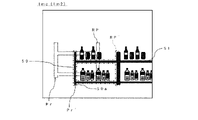
- FIG. 1 shows an example of the overall configuration of the system 1.
- the system 1 monitors the imaging status of the captured image of the imaging target 50 captured by the camera 20 as an imaging device.
- the system 1 is configured to be able to continue to monitor the imaging status of the imaging target 50 in the changed state even if the imaging status changes.
- the system 1 includes a server 10 capable of acquiring an image captured by the camera 20.
- the connection mode between the server 10 and the camera 20 does not matter.
- the connection mode may be a network connection type via a communication network such as the Internet 30, or a direct connection type.
- the connection mode may be wired or wireless.
- the server 10 may be physically formed as one server device, or may be physically formed as a cloud server formed on the cloud by a plurality of server devices.
- the camera 20 may be installed at a predetermined position of either the indoor Idr or the outdoor Odr of the building 40, for example.
- the camera 20 is installed at the camera position CP, which is a predetermined position of the indoor Idr.
- the camera 20 faces the image pickup target 50 side so as to image the image pickup target 50.
- the camera position CP of the camera 20 is the adhesive portion 20a of the member for installing the camera 20 to the store 40, but the present invention is not limited to this.
- the camera position CP may be a position that can be specified as the position of the Idr in the store where the camera 20 is installed.
- the camera 20 may be configured to image the image pickup target 50 periodically (for example, once to several times an hour).
- the camera 20 may be installed at the camera position of the outdoor Odr and image the image pickup target 50 arranged in the outdoor Odr.
- the building 40 is, for example, a store 40 that sells food (including a food floor such as a supermarket or a department store, a food specialty store, a store that sells food, a sales corner, and the like).
- the image pickup target 50 is an individual placed at the placement position AP, which is a predetermined position of the indoor Idr.
- the image pickup target 50 may be a part of the immovable body of the indoor Idr at a predetermined position.
- the image pickup target 50 has a predetermined shape.
- the image pickup target 50 may be fixed to the arrangement position AP, for example, or may be movable when some condition is satisfied (for example, when some force is applied).
- the image pickup target 50 is, for example, a fixture 50 in which food is displayed in the store 40.
- the arrangement position AP of the fixture 50 is specified by the position of the end portion 50a of the leg portion of the fixture 50, but the present invention is not limited to this.
- the placement position AP may be a position that can be specified as the position of the Idr in the store where the fixture 50 is placed.
- the server 10 monitors the imaging status of the imaging target 50 based on the captured image captured (that is, captured) by the camera 20. That is, in the present embodiment, the server 10 monitors the imaging status of the fixture 50 based on the captured image captured by the camera 20 and determines whether or not the imaging status has changed.
- the imaging situation includes, for example, the angle of view of the camera 20, the imaging environment (weather, illuminance, etc.) and the like.
- the "angle of view” refers to the relative positional relationship between the image pickup target 50 and the camera 20.
- “Change in angle of view” refers to a change in the relative positional relationship between the image pickup target 50 and the camera 20.
- the "change in angle of view” may include, for example, a change in the position of the fixture 50, a change in the orientation of the camera 20, a change in the position of the camera 20, and the like.
- the image server 10 used for monitoring the imaging status determines whether or not there is a change in the imaging status by comparing the reference image and the comparison image with reference to each other. The reference image and the comparative image will be described with reference to FIGS. 2 and 3.
- FIG. 2 is an example of the reference image Imr referred to by the server 10.
- the reference image Imr is a captured image of the fixture 50 arranged at the arrangement position AP.
- the reference image Imr is referred to as a reference when the server 10 determines whether or not there has been a change in the imaging status.
- the reference image Imr may be generated, for example, based on a plurality of first captured images Im1 captured by the camera 20 over time by the camera 20 during a predetermined period. The method of generating the reference image Imr will be described later.
- the reference image Imr shows a state in which the fixture 50 to be imaged and the fixture 51 adjacent to the fixture 50 are reflected in the field of view of the camera 20. As shown in FIG.
- a plurality of products 60 may be displayed on each shelf of the fixture 50, and a plurality of products 61 may be displayed on each shelf of the fixture 51.
- the image portions in which each of the fixture 50, the fixture 51, the plurality of products 60, and the plurality of products 61 is reflected in the reference image Imr will be described with the same reference numerals.
- the portion corresponding to the fixture 50 is referred to as “reference portion RP" (dotted line portion).
- the position of the reference portion RP may be specified as the position of the end portion 50a of one leg of the reflected fixture 50.
- the position of the reference portion RP (hereinafter referred to as “reference position Pr”) corresponds to the arrangement position AP of the fixture 50 in the store 40.
- the reference partial RP contains multiple fixed points.
- the fixed point is a point that can be regarded as an invariant position or an invariant position between a plurality of first captured images. Each of the plurality of fixed points may correspond to each of the plurality of feature points of the fixture 50.
- Each feature point of the fixture 50 is typically a feature of the shape of the fixture 50, for example, each end point of the fixture 50, the apex of each corner, and the like.
- the plurality of feature points of the fixture 50 may be set so that the shape of the fixture 50 is specified by, for example, an aggregate of the feature points.
- Each feature point is specified by, for example, a position and a feature amount (image gradient, etc.).
- the end portion 50a of one leg of the reflected fixture 50 may be a fixed point.
- the reference image Imr may be generated by, for example, the server 10. Further, the reference image Imr may be appropriately updated by, for example, the server 10.
- the reference image information which is information about the reference image Imr, may be held by, for example, the server 10.
- the reference image information includes fixed point information (for example, position and feature amount) capable of identifying each of the plurality of fixed points included in the reference portion RP.
- FIG. 3 shows an example of the comparative image Imc referred to by the server 10.
- the comparative image Imc may be, for example, the second captured image Im2 captured by the camera 20 after a predetermined period for capturing the first captured image Im1 (for example, after the generation of the reference image information of the reference image Imr).
- the reference portion RP'(dashed line portion) corresponding to the reference portion RP is located at the position Pr'. That is, in the example of FIG. 3, the comparative image Imc shows a state in which the reference portion RP has moved (that is, changed) from the reference position Pr to the position Pr'.
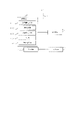
- FIG. 4 is a block diagram showing an example of the configuration of the server 10.
- the server 10 includes a storage device 11, an arithmetic unit 12, and an input device 13. Further, the server 10 may include an output device 14. The storage device 11, the arithmetic unit 12, the input device 13, and the output device 14 may be connected via the data bus 15.
- the storage device 11 can store desired data.
- the storage device 11 may temporarily store the computer program executed by the arithmetic unit 12.
- the storage device 11 may temporarily store data temporarily used by the arithmetic unit 12 while the arithmetic unit 12 is executing a computer program.
- the storage device 11 may store data stored by the server 10 for a long period of time, such as reference image information regarding the reference image Imr.
- the storage device 11 may include at least one of a RAM (Random Access Memory), a ROM (Read Only Memory), a hard disk device, a magneto-optical disk device, an SSD (Solid State Drive), and a disk array device. good. That is, the storage device 11 may include a volatile recording medium and a non-volatile recording medium.
- the arithmetic unit 12 includes, for example, a CPU (Central Processing Unit).
- the arithmetic unit 12 may be, for example, a computer unit including a CPU and a recording medium such as a RAM and a ROM for recording various information necessary for the operation of the CPU.
- the arithmetic unit 12 reads a computer program.
- the arithmetic unit 12 may read the computer program stored in the storage device 11.
- the arithmetic unit 12 may read a computer program that can be read by a computer and is stored in the non-volatile recording medium by using a recording medium reading device (not shown).
- the arithmetic unit 12 may acquire a computer program from a device (not shown) located outside the server 10 via the input device 13 (that is, it may be downloaded or read). The arithmetic unit 12 executes the read computer program. As a result, a logical functional block for executing the operation to be performed by the server 10 is realized in the arithmetic unit 12. That is, the arithmetic unit 12 can function as a controller for realizing a logical functional block for executing an operation to be performed by the server 10.
- FIG. 4 shows an example of a logical functional block realized in the arithmetic unit 12 in order to perform each process in the system 1.
- a reference image generation unit 121 an image acquisition unit 122, an image pickup status monitoring unit 123, an output unit 124, and an image reacquisition unit 125 are realized in the arithmetic unit 12. The details of the operation of each part 121 to 125 will be described later.
- the input device 13 is a device that receives input of information to the server 10 from the outside of the server 10.
- the input device 13 may accept input (that is, reception) of information by communication.
- the input device 13 may directly or indirectly acquire (that is, receive) various information such as a captured image captured by the camera 20 from the camera 20.
- the output device 14 is a device that outputs information to the outside of the server 10.
- the output device 14 may output information about each process performed by the server 10 in a user-recognizable output mode. Further, the output device 14 may output (that is, transmit) various information to another server or system.
- the output mode recognizable by the user includes, for example, display output by a screen or the like as an output device 14, audio output by a speaker or the like as an output device 14, print output by a printer or the like as an output device 14, and the like.
- the reference image generation unit 121 detects the reference portion RP based on a plurality of first captured images Im1 captured during a predetermined period by the fixture 50 arranged at the arrangement position AP of the Idr in the store, and the reference image. Generate reference image information about Imr. Further, even if the reference image generation unit 121 generates a new reference image Imr based on the state of the fixture 50 after the change, for example, when the angle of view of the camera 20 changes (for example, when the fixture 50 moves). good.
- the image acquisition unit 122 may, for example, capture a comparative image Imc (that is, a second captured image) of the fixture 50 captured by the camera 20 after a predetermined period of time when the first captured image Im1 is captured (for example, after the generation of the reference image information). Im2) is acquired via the input device 13.
- the image acquisition unit 122 may periodically acquire the comparative image Imc at predetermined time intervals (for example, once every 30 minutes or once an hour). Further, the image acquisition unit 122 may acquire a plurality of first captured images Im1 for generating the reference image Imr via the input device 13.
- the imaging status monitoring unit 123 monitors the imaging status of the captured image of the fixture 50 based on the reference image Imr and the comparative image Imc (second captured image Im2).
- the image pickup status monitoring unit 123 is, for example, based on the relationship between the reference position Pr of the reference portion RP in the reference image Imr and the position Pr'of the reference portion RP'in the comparison image Imc (second captured image Im2). Determine the imaging status of whether or not imaging is possible.
- the image pickup status monitoring unit 123 is, for example, when the reference portion RP'is not detected near the reference position Pr in the comparative image Imcc (for example, when the difference between the reference position Pr and the position Pr'exceeds a predetermined first threshold value. ), It may be determined that the fixture 50 cannot be imaged.
- the output unit 124 outputs, for example, information on the imaging status of the comparative image Imc from the output device 14 according to the difference between the reference position Pr of the reference portion RP and the position Pr'of the reference portion RP'. For example, when a plurality of levels are set for the difference, the output unit 124 may output a notification (for example, a warning or a confirmation recommendation) corresponding to each level from the output device 14. Alternatively, for example, when a predetermined second threshold value (> first threshold value) is set for the difference, the output unit 124 receives a predetermined notification (for example, a warning or a warning) when the difference exceeds the second threshold value.
- the confirmation recommendation may be output from the output device 14.
- the "notification" includes, for example, an abnormality occurrence warning of the captured image, a state confirmation recommendation of the camera 20, a state confirmation recommendation of the fixture 50, and the like.
- the image re-acquisition unit 125 caused the camera 20 to re-image the fixture 50 and re-imaged it by the image acquisition unit 122.
- the first captured image Im1 or the re-imaged second captured image Im2 is reacquired.
- the image acquisition unit 122 may reacquire the first captured image Im1 or the second captured image Im2 stored by the camera 20.
- the server 10 generates the reference image Imr and monitors the imaging status of the fixture 50 based on the reference image Imr and the comparison image Imc. Then, the server 10 updates the reference image Imr, for example, when the angle of view of the camera 20 changes.
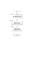
- the flow of processing performed by the server 10 will be described with reference to FIGS. 5 to 7. First, an example of the flow of processing related to the generation of the reference image Imr will be described with reference to FIG.
- the processing routine shown in FIG. 5 is performed by the reference image generation unit 121 of the server 10.
- the server 10 first performs the first captured image acquisition process (step S100).
- the server 10 causes, for example, the image acquisition unit 122 to acquire a plurality of first captured images Im1 captured within a predetermined time.
- the “predetermined time” is, for example, a time preset as a time for capturing a plurality of first captured images Im1 for generating a reference image Imr.
- the "predetermined time” may be, for example, about several seconds.
- the number of first captured images Im1 to be captured may be any number as long as it can be captured within a predetermined time.
- the server 10 performs the reference partial detection process (step S101).
- the server 10 first extracts a plurality of feature points from each of the plurality of first captured images Im1.
- the feature points are specified by, for example, a position and a feature amount. Therefore, for example, the server 10 may generate feature point information including a position and a feature amount for each feature point and store it in the storage device 11.
- the server 10 identifies a feature point whose position is invariant or can be regarded as invariant in position among a plurality of first captured images Im1 as a fixed point.
- a fixed point is also specified by, for example, a position and a feature amount, like a feature point.
- the server 10 may generate fixed point information including a position and a feature amount for each specified fixed point and store it in the storage device 11.
- the server 10 may store, for example, the feature point information of the corresponding feature point in the storage device 11 as the fixed point information.
- the set of fixed points identified corresponds to the reference partial RP. As a result, the reference partial RP is detected.
- the server 10 may use the shape information regarding the shape (that is, the two-dimensional shape) of the fixture 50 reflected in the captured image of the camera 20.
- the server 10 may use the shape information to extract an image portion in which the fixture 50 is reflected from each first captured image Im1 and extract feature points by focusing on the extracted image portion. good.
- the shape information of the fixture 50 may be stored in the storage device 11 for a long period of time, for example.
- the shape information of the fixture 50 may be input via the input device 13 each time it is used and temporarily stored in the storage device 11.
- the server 10 performs a reference image generation process following the reference partial detection process (step S101) (step S102).
- a reference image Imr including a reference portion RP which is an aggregate of the specified fixed points, is generated.
- the server 10 generates reference image information regarding the generated reference image Imr and stores it in, for example, a storage device 11.
- the reference image information includes fixed point information regarding a plurality of fixed points included in the reference portion RP.
- the server 10 may appropriately refer to the reference image information when processing the reference image Imr, for example.
- the server 10 may generate a reference image Imr according to the imaging environment.
- the server 10 may generate a reference image Imr according to the illuminance level (that is, the brightness level) of the Idr in the store, for example.
- the server 10 may specify, for example, the illuminance level of the in-store Idr when the reference image Imr is generated, and set the generated reference image Imr as the reference image Imr for the specified illuminance level.
- the server 10 may acquire the weather information at the time of imaging from a predetermined weather information providing site, and specify the illuminance level at the time of imaging from the acquired weather information. And / or, for example, the server 10 may specify the illuminance level at the time of imaging from the imaging date and time.
- the server 10 may generate the reference image Imr by the generation method described above for each different illuminance level, for example.
- the server 10 may obtain a reference image Imr for another illuminance level by a predetermined formula, a predetermined calculation model, or the like, based on the illuminance level corresponding to the generated reference image Imr.
- Each illuminance level may be appropriately set according to the imaging environment of the actual imaging site.
- the server 10 may store the image pickup environment information (for example, the illuminance level) regarding the image pickup environment and the reference image Imr in association with each other, for example, in the storage device 11.
- the server 10 may detect the reference portion RP and generate the reference image Imr by extracting a plurality of feature points related to the fixture 50 from one first captured image Im1 as a plurality of fixed points. Further, in step S101, for example, when the reference portion RP cannot be detected due to a defect of at least one first captured image Im1, the server 10 reacquires at least one first captured image Im1 by the image reacquisition unit 125. You may.
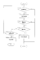
- the processing routine shown in FIG. 7 is performed, for example, after the generation of the reference image information regarding the first reference image Imr.
- the processing routine shown in FIG. 7 is executed by the arithmetic unit 12 of the server 10.
- the server 10 determines whether or not the image acquisition unit 122 has acquired the comparative image Imc from the camera 20 (step S200). The server 10 repeats step S200 until the comparative image Imc is acquired from the camera 20.
- the server 10 performs the feature point extraction process (step S201).
- the server 10 extracts a plurality of feature points from the acquired comparative image Imcc and acquires feature point information (position and feature amount) of each feature point.
- the server 10 may use the above-mentioned shape information when extracting feature points.
- the server 10 determines whether or not there has been a change in the imaging status (step S202).
- step S201 for example, in the comparative image Imcc, when the feature points can be extracted at the positions of the fixed points included in the reference portion RP (or the positions that can be regarded as the positions of the fixed points), the server 10 determines. It may be determined that there is no change in the imaging condition. For example, in the server 10, when the difference between the fixed point position Pr included in the reference portion RP and the feature point position Pr ′ corresponding to the fixed point in the comparative image Imc is within the first threshold value, the fixed point position It may be determined that the feature point can be extracted at (or a position that can be regarded as the position of the fixed point).
- the server 10 moves to the fixed point position (or a position that can be regarded as the fixed point position). It may be determined that the feature points could not be extracted. That is, when the difference between the reference position Pr of the reference portion RP and the position Pr'of the reference portion RP'corresponding to the reference portion RP in the comparative image Imc is within the first threshold value, the server 10 determines the position of the fixed point ( Alternatively, it may be determined that the feature points have been extracted at the positions that can be regarded as the positions of the fixed points).
- the server 10 when the difference between the reference position Pr of the reference portion RP and the position Pr'of the reference portion RP'exceeds the first threshold value, the server 10 is regarded as the position of the fixed point (or the position of the fixed point). It may be determined that the feature points could not be extracted at the obtained position). For example, when a plurality of feature points are extracted near the fixed point position Pr, the server 10 may specify the feature point closest to the fixed point position Pr as the feature point corresponding to the fixed point. ..
- step S202 When it is determined that there is no change in the imaging status (step S202: No), the server 10 returns to step S200.
- step S201 for example, in the comparative image Imcc, when the feature point cannot be extracted at the position of any fixed point (or the position that can be regarded as the position of the fixed point), the server 10 is in the imaging situation. Determine that there is a change.
- step S202: Yes the server 10 determines whether or not the angle of view of the camera 20 has changed (step S203).
- the server 10 is, for example, when the difference between the position Pr of the fixed point included in the reference portion RP and the position Pr'of the feature point corresponding to the fixed point in the comparative image Imc is within the second threshold value (for example, furniture). It may be determined that the angle of view of the camera 20 has changed (the position of 50 has moved). That is, for example, when the difference between the reference position Pr of the reference portion RP and the position Pr'of the reference portion RP'corresponding to the reference portion RP in the comparative image Imc is within the second threshold value, the server 10 has the camera 20. It may be determined that the angle of view has changed.
- the second threshold value for example, furniture
- step S203: Yes the server 10 determines that the angle of view of the camera 20 has changed.
- step S204 for processing when the angle of view of the camera 20 changes.
- the server 10 may determine that an abnormality has occurred in the imaging status.
- step S203: No the server 10 proceeds to step S205.
- the difference threshold value (at least one of the first threshold value and the second threshold value) used in each of steps S202 and S203 may be set according to the imaging environment.
- a threshold value for the difference may be set according to the illuminance level of Idr in the store.
- the server 10 can determine the imaging status in consideration of the difference in the illuminance of the Idr in the store based on the weather and the date and time by using, for example, the threshold value of the difference corresponding to the illuminance level of the Idr in the store.
- the server 10 may acquire the weather information at the time of imaging from a predetermined weather information providing site, and specify the illuminance level at the time of imaging from the acquired weather information. And / or, for example, the server 10 may specify the illuminance level at the time of imaging from the imaging date and time.
- step S204 the server 10 performs the reference partial update process.
- the reference partial update process is performed when it is determined that the angle of view of the camera 20 has changed.
- the server 10 generates a new reference image Imr based on the state in which the reference portion RP has moved (that is, the comparative image Immc), and updates the reference image information based on the new reference image Imr.
- the server 10 may set, for example, the comparative image Imc as the new reference image Imr. Therefore, the server 10 may use the reference portion RP'in the comparative image Imc as the new reference portion RP in the new reference image Imr.
- the server 10 may set, for example, a feature point at the position Pr'in the comparative image Imc as a new fixed point at the new reference position Pr in the new reference image Imr.
- a feature point at the position Pr'in the comparative image Imc is set as a new fixed point at the new reference position Pr in the new reference image Imr.
- the new reference portion RP in the new reference image Imr is specified.
- the server 10 updates the reference image information with a plurality of new fixed points included in the new reference portion RP so that the reference image information becomes information about the new reference image Imr.
- the server 10 returns to step S200 so as to continue the monitoring process based on the updated reference image information.
- the server 10 may generate the new reference image Imr by the processing routine shown in FIG. That is, the server 10 may generate a new reference image Imr based on a plurality of first captured images Im1 captured over time in a predetermined period. Further, the new reference image Imr may be generated according to the imaging environment. For example, as described above, the server 10 may generate a new reference image Imr according to the illuminance level of the Idr in the store.
- step S205 the server 10 determines whether or not the comparative image Imc has been reacquired. If the comparative image Imc is not reacquired (step S205: No), the process returns to step S200 to reacquire the comparative image Imc. When the comparative image Imc is reacquired (step S205: Yes), the abnormality status processing is performed (step S206).
- the server 10 may acquire the comparative image Imc twice or more. In this case, the server 10 may manage the number of times the comparative image Imc is reacquired.
- the server 10 determines, for example, the imaging status in which the comparative image Imc is captured, and outputs a notification to the user according to the determined imaging status via the output device 14. May be good. Notifications to users include, for example, warnings and confirmation recommendations. For example, when the difference between the position Pr'of the reference portion RP'and the reference position Pr in the comparative image Imc exceeds the second threshold value, it is determined that the angle of view of the camera 20 has changed beyond the assumed range, and the user is notified. You may recommend on-site confirmation. For example, when the reference portion RP'is not detected from the comparative image Imc, the server 10 may determine that some abnormality has occurred and recommend the user to confirm the site.
- the server 10 determines that the comparative image Imc indicates a state in which the comparative image Imc can be determined to be bad weather (for example, a state in which it can be determined to be affected by snow or raindrops), the comparative image Imc may be determined to be in bad weather. You may notify the user that you cannot get it. As a result, it is possible to avoid making the abnormality of the comparative image Imc due to bad weather into an abnormality of the imaging condition.
- the server 10 may have information about an image indicating a state that can be determined to be bad weather in the storage device 11. The server 10 ends the processing routine of FIG. 7 after step S206.
- the server 10 may restart the processing routine of FIG. 7, for example, when it is determined that the weather is such that the comparative image Imc can be obtained.
- the server 10 may restart the processing routine of FIG. 7 after a predetermined time has elapsed from the end of the processing routine of FIG. 7, for example.
- the server 10 may accept, for example, an input by the user via the input device 13.
- the server 10 may acquire information on the weather in the vicinity of the store 40 from the weather information providing site that provides the weather information.
- the server 10 may appropriately specify and use the reference image Imr suitable for the imaging environment.
- the server 10 may specify the illuminance level at the time of imaging from the date and time at the time of imaging (or the illuminance sensor provided in the store 40), and may use the reference image Imr corresponding to the specified illuminance level.
- the server 10 acquires the weather information at the time of imaging from a predetermined weather information providing site, specifies the illuminance level at the time of imaging from the acquired weather information, and uses the reference image Imr corresponding to the specified illuminance level. You can do it.
- the server 10 may specify the illuminance level at the time of imaging from the imaging date and time.
- step S200 is performed by the image acquisition unit 122 of the server 10.
- Steps S201 to S203 are performed by the image pickup status monitoring unit 123 of the server 10.
- Step S204 is performed by the reference image generation unit 121 of the server 10.
- Step S205 is performed by the image reacquisition unit 125 of the server 10.
- Step S206 is performed by the output unit 124 of the server 10.
- the imaging status monitoring system includes a reference image generation unit that generates reference image information regarding a reference image including a reference portion based on a first captured image in which an image pickup target is captured during a predetermined period, and the predetermined period.
- the image pickup status monitoring unit for determining the imaging status of whether or not the imaging target can be imaged is provided, and the reference image generation unit includes the position of the reference portion and the position of the corresponding portion in the reference image.
- the image pickup status monitoring system uses the position of the reference portion included in the reference image information as the position of the corresponding portion.
- the reference portion of the reference image information is determined.
- the position of is updated to the changed position. This makes it possible to continue monitoring the imaging status with the automatically updated reference image even if the position of the imaging target changes.
- the reference image information has information on the imaging environment
- the imaging status monitoring unit has a difference between the position of the reference portion and the position of the corresponding portion and a predetermined threshold value.
- the imaging status monitoring system according to Appendix 1 wherein the imaging status is determined based on the above, and the predetermined threshold value is set based on the imaging environment.
- the imaging status can be determined based on the difference between the position of the reference portion and the position of the corresponding portion with a threshold value according to the imaging environment.
- a threshold value for example, the illuminance level at which the second image is acquired can be considered as the imaging environment, and more accurate determination can be made.
- the imaging status monitoring system according to Appendix 3 further includes an output unit that performs processing related to output that outputs the imaging status to the user based on the difference between the position of the reference portion and the position of the corresponding portion.
- the imaging status monitoring system according to Appendix 1 or Appendix 2 is provided.
- a warning or confirmation recommendation is given to the user. Is possible. Alternatively, the user may be notified as necessary depending on the level of the magnitude of the difference.
- the imaging status monitoring system includes the shape information of the imaging target, and the reference image generation unit uses the portion corresponding to the shape information as the reference portion in the first captured image.
- the image pickup status monitoring system according to any one of 3 to 3.
- the reference image generation unit can use the shape information like a template when extracting feature points in the first captured image.
- the reference image generation unit can extract the image portion in which the image pickup target is reflected from the first captured image by using this shape information, and can extract the feature points by focusing on the extracted image portion. .. Therefore, it is possible to avoid extracting the feature points of the image portion in which another object that is not the image pickup target is captured. For example, when there is an object other than the image pickup target, the captured image obtained by capturing the image pickup target in the state where the other object exists can be used as the first captured image.
- the image pickup status monitoring system is an image reacquisition unit that causes an image pickup device to re-image the image pickup target and re-acquires the second image capture image when the corresponding portion is not extracted from the second image capture image.
- the image pickup status monitoring system according to any one of Supplementary note 1 to 4, further comprising.
- the reference image generation means may generate a reference image according to the imaging environment. Therefore, the reference image generation means has (i) a first reference based on the plurality of first captured images generated by the imaging target being imaged by the imaging device in the first imaging environment.
- a second reference image information different from the first reference image information may be generated.
- the reference image generation unit changes among the plurality of first captured images based on the plurality of first captured images captured by the imaging target during the predetermined period.
- the image pickup status monitoring system according to any one of Supplementary note 1 to 5, wherein the reference image information regarding the reference image is generated by using the portion without the reference portion as the reference portion.
- the reference image generation unit generates a reference image from a plurality of first captured images. For example, even if the first captured image in an abnormal state is acquired due to a temporary factor (for example, when an object or a person passes between the imaged object and the camera), the reference image generation unit is used. Can generate a reference image using a portion that does not change based on the first captured image in another normal state as a reference portion.
- the reference portion includes at least one feature point of the imaging target as a fixed point
- the reference image information includes fixed point information regarding the fixed point included in the reference portion.
- the imaging status monitoring unit determines the imaging status based on the relationship between the position of the fixed point in the reference image and the position of the corresponding portion
- the reference image generation unit determines the imaging status in the reference image. If the position of the fixed point is different from the position of the corresponding portion, the position of the reference portion included in the reference image information is set as the position of the corresponding portion in the second captured image, whichever is one of Supplementary note 1 to 6.
- the reference portion of the reference image can be treated as an aggregate of a plurality of fixed points. Therefore, for example, the position of the reference portion can be specified as the position of the fixed point.
- the imaging status monitoring method generates reference image information regarding a reference image including a reference portion based on a first captured image in which an image pickup target is captured during a predetermined period, and after the predetermined period, the imaging target is captured.
- the captured second captured image can be acquired, and the image pickup target can be imaged based on the relationship between the position of the reference portion in the reference image and the position of the corresponding portion corresponding to the reference portion in the second captured image.
- the position of the reference portion included in the reference image information is set to the position of the corresponding portion.
- the position of the reference portion that serves as a reference for the position of the imaging target under the monitoring of the imaging status of the imaging target similar to the imaging status monitoring system described in Appendix 1.
- the position of the reference portion of the reference image information is updated to the changed position. This makes it possible to continue monitoring the imaging status with the automatically updated reference image even if the position of the imaging target changes.
- the recording medium according to Appendix 9 is a reference image generation unit that generates reference image information about a reference image including a reference portion based on a first captured image in which an image pickup target is captured by a computer during a predetermined period, the predetermined period.
- the reference image generation unit functions as an imaging status monitoring unit that determines the imaging status of whether or not the imaging target can be imaged, and the reference image generation unit has the position of the reference portion in the reference image and the corresponding portion.
- the position is different, it is a recording medium on which a computer program configured to set the position of the reference portion included in the reference image information as the position of the corresponding portion is recorded.
- the imaging status monitoring system described in Appendix 1 can be realized.
- the present invention can be appropriately modified within the scope of the claims and within the scope not contrary to the gist or idea of the invention which can be read from the entire specification, and the inventory management system, the inventory management method, and the recording medium accompanied by such changes are also made. It is included in the technical idea of the present invention.
- Imaging status monitoring system 10 Server 20 Camera (imaging device) 50 Fixtures (target for imaging) RP, RP'Reference part Imr Reference image Im1 First captured image Im2 Second captured image 121 Reference image generation unit 122 Image acquisition unit 123 Image capture status monitoring unit 124 Output unit 125 Image reacquisition unit
Landscapes
- Engineering & Computer Science (AREA)
- Computer Vision & Pattern Recognition (AREA)
- Physics & Mathematics (AREA)
- General Physics & Mathematics (AREA)
- Theoretical Computer Science (AREA)
- Multimedia (AREA)
- Signal Processing (AREA)
- Studio Devices (AREA)
- Closed-Circuit Television Systems (AREA)
- Image Analysis (AREA)
- Alarm Systems (AREA)
Priority Applications (3)
| Application Number | Priority Date | Filing Date | Title |
|---|---|---|---|
| JP2022558615A JP7521590B2 (ja) | 2020-10-26 | 2020-10-26 | 撮像状況監視システム、撮像状況監視方法、及び記録媒体 |
| PCT/JP2020/040119 WO2022091182A1 (ja) | 2020-10-26 | 2020-10-26 | 撮像状況監視システム、撮像状況監視方法、及び記録媒体 |
| US18/032,063 US20230386073A1 (en) | 2020-10-26 | 2020-10-26 | Imaging status monitoring system, imaging status monitoring method, and recording medium |
Applications Claiming Priority (1)
| Application Number | Priority Date | Filing Date | Title |
|---|---|---|---|
| PCT/JP2020/040119 WO2022091182A1 (ja) | 2020-10-26 | 2020-10-26 | 撮像状況監視システム、撮像状況監視方法、及び記録媒体 |
Publications (1)
| Publication Number | Publication Date |
|---|---|
| WO2022091182A1 true WO2022091182A1 (ja) | 2022-05-05 |
Family
ID=81383764
Family Applications (1)
| Application Number | Title | Priority Date | Filing Date |
|---|---|---|---|
| PCT/JP2020/040119 Ceased WO2022091182A1 (ja) | 2020-10-26 | 2020-10-26 | 撮像状況監視システム、撮像状況監視方法、及び記録媒体 |
Country Status (3)
| Country | Link |
|---|---|
| US (1) | US20230386073A1 (https=) |
| JP (1) | JP7521590B2 (https=) |
| WO (1) | WO2022091182A1 (https=) |
Cited By (1)
| Publication number | Priority date | Publication date | Assignee | Title |
|---|---|---|---|---|
| WO2025017855A1 (ja) * | 2023-07-19 | 2025-01-23 | 日本電気株式会社 | 監視装置、監視方法、及び記録媒体 |
Citations (2)
| Publication number | Priority date | Publication date | Assignee | Title |
|---|---|---|---|---|
| JP2002157676A (ja) * | 2000-11-21 | 2002-05-31 | Natl Inst For Land & Infrastructure Management Mlit | 可視画像式路面状況把握装置における路面状況判定方法 |
| WO2014010174A1 (ja) * | 2012-07-12 | 2014-01-16 | 日本電気株式会社 | 画角変動検知装置、画角変動検知方法および画角変動検知プログラム |
-
2020
- 2020-10-26 JP JP2022558615A patent/JP7521590B2/ja active Active
- 2020-10-26 WO PCT/JP2020/040119 patent/WO2022091182A1/ja not_active Ceased
- 2020-10-26 US US18/032,063 patent/US20230386073A1/en active Pending
Patent Citations (2)
| Publication number | Priority date | Publication date | Assignee | Title |
|---|---|---|---|---|
| JP2002157676A (ja) * | 2000-11-21 | 2002-05-31 | Natl Inst For Land & Infrastructure Management Mlit | 可視画像式路面状況把握装置における路面状況判定方法 |
| WO2014010174A1 (ja) * | 2012-07-12 | 2014-01-16 | 日本電気株式会社 | 画角変動検知装置、画角変動検知方法および画角変動検知プログラム |
Cited By (1)
| Publication number | Priority date | Publication date | Assignee | Title |
|---|---|---|---|---|
| WO2025017855A1 (ja) * | 2023-07-19 | 2025-01-23 | 日本電気株式会社 | 監視装置、監視方法、及び記録媒体 |
Also Published As
| Publication number | Publication date |
|---|---|
| JPWO2022091182A1 (https=) | 2022-05-05 |
| US20230386073A1 (en) | 2023-11-30 |
| JP7521590B2 (ja) | 2024-07-24 |
Similar Documents
| Publication | Publication Date | Title |
|---|---|---|
| CN103026720B (zh) | 立体摄像机系统的光学自诊断 | |
| US11468261B2 (en) | Information processing apparatus, image processing method, and computer-readable recording medium recording image processing program | |
| US20120310898A1 (en) | Server and method for managing monitored data | |
| JP2018520416A5 (https=) | ||
| CN105793884A (zh) | 设备维护服务器以及设备维护系统 | |
| JP2014173775A (ja) | 空調制御装置、システム、及び方法 | |
| WO2022091182A1 (ja) | 撮像状況監視システム、撮像状況監視方法、及び記録媒体 | |
| JP6177461B2 (ja) | 監視レコーダ及びその起動方法 | |
| JP7390856B2 (ja) | 修理金額算出システム及び修理金額算出方法 | |
| JP2020199704A (ja) | 電子機器、交換ガイダンスの表示方法およびプログラム | |
| JP2005316808A (ja) | 性能監視装置および性能監視方法並びにプログラム | |
| CN114168435B (zh) | 一种告警处理推荐方法、装置、设备及可读存储介质 | |
| CN105378586A (zh) | 确定电源模块的故障状态 | |
| US20160218945A1 (en) | Monitoring apparatus, system, control method for monitoring apparatus, control method for system, and program | |
| CN111273932B (zh) | 一种部件刷新方法、系统及计算机可读存储介质 | |
| EP2860633A1 (en) | Method for maintaining file system of computer system | |
| CN110333968B (zh) | 应用于数据库的数据管理方法、装置及计算机设备 | |
| US20220207267A1 (en) | Computer-readable recording medium storing detection program, detection method, and detection device | |
| US20230401859A1 (en) | Management apparatus, management method, management system, computer program and recording medium | |
| JP6287434B2 (ja) | 温度制御装置、温度制御方法、及び温度制御プログラム | |
| US9767399B2 (en) | Management apparatus which controls limit value of storage volume of setting data according to type of setting data, control method for controlling management apparatus, storage medium storing program, and system | |
| CN106357948B (zh) | 远端维护系统以及远端维护方法 | |
| JP7476028B2 (ja) | 監視情報処理装置、方法およびプログラム | |
| CN111931682B (zh) | 一种异常行为检测方法及装置 | |
| US10642450B2 (en) | Information processing apparatus |
Legal Events
| Date | Code | Title | Description |
|---|---|---|---|
| 121 | Ep: the epo has been informed by wipo that ep was designated in this application |
Ref document number: 20959700 Country of ref document: EP Kind code of ref document: A1 |
|
| ENP | Entry into the national phase |
Ref document number: 2022558615 Country of ref document: JP Kind code of ref document: A |
|
| WWE | Wipo information: entry into national phase |
Ref document number: 18032063 Country of ref document: US |
|
| NENP | Non-entry into the national phase |
Ref country code: DE |
|
| 122 | Ep: pct application non-entry in european phase |
Ref document number: 20959700 Country of ref document: EP Kind code of ref document: A1 |