WO2022085655A1 - Wind turbine blade, wind turbine blade monitoring device, wind power generation device, and wind turbine blade monitoring method - Google Patents
Wind turbine blade, wind turbine blade monitoring device, wind power generation device, and wind turbine blade monitoring method Download PDFInfo
- Publication number
- WO2022085655A1 WO2022085655A1 PCT/JP2021/038514 JP2021038514W WO2022085655A1 WO 2022085655 A1 WO2022085655 A1 WO 2022085655A1 JP 2021038514 W JP2021038514 W JP 2021038514W WO 2022085655 A1 WO2022085655 A1 WO 2022085655A1
- Authority
- WO
- WIPO (PCT)
- Prior art keywords
- wind turbine
- magnetic field
- wing
- turbine blade
- pair
- Prior art date
Links
Images


Classifications
-
- F—MECHANICAL ENGINEERING; LIGHTING; HEATING; WEAPONS; BLASTING
- F03—MACHINES OR ENGINES FOR LIQUIDS; WIND, SPRING, OR WEIGHT MOTORS; PRODUCING MECHANICAL POWER OR A REACTIVE PROPULSIVE THRUST, NOT OTHERWISE PROVIDED FOR
- F03D—WIND MOTORS
- F03D17/00—Monitoring or testing of wind motors, e.g. diagnostics
-
- F—MECHANICAL ENGINEERING; LIGHTING; HEATING; WEAPONS; BLASTING
- F03—MACHINES OR ENGINES FOR LIQUIDS; WIND, SPRING, OR WEIGHT MOTORS; PRODUCING MECHANICAL POWER OR A REACTIVE PROPULSIVE THRUST, NOT OTHERWISE PROVIDED FOR
- F03D—WIND MOTORS
- F03D80/00—Details, components or accessories not provided for in groups F03D1/00 - F03D17/00
- F03D80/30—Lightning protection
-
- Y—GENERAL TAGGING OF NEW TECHNOLOGICAL DEVELOPMENTS; GENERAL TAGGING OF CROSS-SECTIONAL TECHNOLOGIES SPANNING OVER SEVERAL SECTIONS OF THE IPC; TECHNICAL SUBJECTS COVERED BY FORMER USPC CROSS-REFERENCE ART COLLECTIONS [XRACs] AND DIGESTS
- Y02—TECHNOLOGIES OR APPLICATIONS FOR MITIGATION OR ADAPTATION AGAINST CLIMATE CHANGE
- Y02E—REDUCTION OF GREENHOUSE GAS [GHG] EMISSIONS, RELATED TO ENERGY GENERATION, TRANSMISSION OR DISTRIBUTION
- Y02E10/00—Energy generation through renewable energy sources
- Y02E10/70—Wind energy
- Y02E10/72—Wind turbines with rotation axis in wind direction
Definitions
- the present disclosure relates to a wind turbine wing, a wind turbine wing monitoring device and a wind power generation device, and a method for monitoring the wind turbine wing.
- the wind turbine wing is provided with a receptor (lightning receiving part) as a device for protecting the wind turbine wing from lightning.
- the receptor is provided at the tip of the wind turbine wing and other places, and is electrically connected to the down conductor (pulling conductor) extending the wind turbine wing and the wind turbine tower. The lightning current when a lightning strike occurs on the receptor is guided to the ground via the down conductor and discharged.
- Patent Document 1 discloses a lightning strike detection system for a wind turbine blade provided with a plurality of receptors.
- This lightning strike detection system includes a plurality of current sensors, each of which is provided corresponding to a plurality of receptors.
- the plurality of current sensors each detect the current flowing through the branch line (conductor) connecting the plurality of receptors and the conductor (down conductor) extending inside the wind turbine blade. Then, based on the detection results of a plurality of current sensors, it is possible to detect that there is a lightning strike on the wind turbine blade and identify the receptor that has been hit by lightning.
- the wind turbine wing is provided with a receptor, it may be hit by a lightning strike at a place other than the place where the receptor is installed, for example, the surface of the wing body (shell, etc.). Therefore, in order to properly or promptly perform maintenance when the wind turbine wing is damaged by a lightning strike, it is desirable to be able to appropriately identify the position of the lightning strike on the wind turbine wing.
- At least one embodiment of the present invention provides a wind turbine wing, a wind turbine wing monitoring device and a wind power generation device, and a method for monitoring the wind turbine wing, which can appropriately identify the position of a lightning strike on the wind turbine wing.
- the wind turbine blade according to at least one embodiment of the present invention is With the wing body, A down conductor extending along the longitudinal direction of the wing body, At least a pair of magnetic field sensors arranged inside the wing body at positions sandwiching the down conductor and for detecting a local magnetic field at each of the positions. To prepare for.
- the monitoring device is A wind turbine wing monitoring device comprising a wing body and a down conductor extending along the longitudinal direction of the wing body. At least a pair of magnetic field sensors provided in the wind turbine blade at a position sandwiching the down conductor inside the blade body and for detecting a local magnetic field at each of the positions. Based on the detection signals of each of the at least a pair of magnetic field sensors, a lightning position information acquisition unit for obtaining information on the lightning position of the wind turbine blade, and a lightning position information acquisition unit. To prepare for.
- the wind power generation device is With the wind turbine rotor including the above-mentioned wind turbine blades, A generator configured to be driven by the rotation of the wind turbine rotor, A monitoring device including a lightning position information acquisition unit for obtaining information on the lightning position of the wind turbine blade based on the detection signals of each of the at least a pair of magnetic field sensors. To prepare for.
- a wind turbine wing a wind turbine wing monitoring device and a wind power generation device, and a method for monitoring the wind turbine wing, which can appropriately identify the position of a lightning strike on the wind turbine wing.
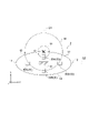
- FIG. 1 is a schematic diagram of a wind turbine generator to which a wind turbine blade or a monitoring device according to some embodiments is applied.
- 2 and 3 are schematic views of a wind turbine blade according to an embodiment. 2 is a cross-sectional view orthogonal to the longitudinal direction of the wind turbine blade, and FIG. 3 is a cross-sectional view taken along the line AA of FIG.
- FIG. 4 is a schematic configuration diagram of monitoring according to an embodiment.
- the wind power generation device 1 includes a rotor (wind turbine rotor) 5 composed of at least one (for example, three) wind turbine blades 2 and a hub 4.
- the wind turbine blade 2 is radially attached to the hub 4, and is configured to rotate the rotor 5 by receiving wind from the wind turbine blade 2 to drive a generator (not shown) connected to the rotor 5.
- the rotor 5 is supported by a nacelle 8 provided above the tower 6.
- the tower 6 may be erected on a foundation structure such as a foundation structure or a floating structure provided on water or on land.
- the wind turbine blade 2 has a blade body 10 including a shell (skin) and a down conductor extending along the longitudinal direction of the blade body 10 (hereinafter, also simply referred to as the longitudinal direction). 24 and at least a pair of magnetic field sensors 30 provided inside the blade body 10.
- the wing body 10 is provided between the wing root 15 attached to the hub 4 of the wind power generator 1, the wing root 16 located farthest from the hub 4, and between the wing root 15 and the wing tip 16. Includes an extending wing shape. Further, as shown in FIGS. 2 and 3, the wing body 10 has a leading edge 11 and a trailing edge 12 from the wing root 15 to the wing tip 16. Further, the outer shape of the wing body 10 is formed by a negative pressure surface (back surface) 13 and a pressure surface (ventral surface) 14. The negative pressure surface 13 and the pressure surface 14 of the blade body 10 include the surface of the shell.
- the wing body 10 may be made of fiber reinforced plastic.
- the wing body 10 is provided with a receptacle (lightning receiving portion) 20.
- the receptacle 20 is made of a conductive material and is typically made of metal.
- the receptor 20 is provided on the surface (negative pressure surface 13 or pressure surface 14) of the blade body 10 at a position on the blade root 15 side in the longitudinal direction from the receptor 21 provided in the region including the blade tip 16 and / or the region.
- the receptacle 22 provided may be included.
- the down conductor 24 of the wind turbine blade 2 is composed of, for example, a conducting wire, is electrically connected to each of the above-mentioned receptors 20, and is connected to the down conductor 26 extending inside the tower 6.
- the lightning current when a lightning strike occurs on the wind turbine blade 2 (receptor 20 or the like) is guided to the outside of the wind power generation device 1 such as the ground via the down conductor 24 and the down conductor 26.
- the down conductor 24 may extend along the longitudinal direction inside the blade body 10, for example, as shown in FIG. Alternatively, the down conductor 24 may extend along the longitudinal direction along the surface of the blade body 10 (negative pressure surface 13 or pressure surface 14) (see FIGS. 6A and 6B).
- At least a pair of magnetic field sensors 30 are arranged at positions on both sides of the down conductor 24 inside the blade body 10, and are configured to detect a local magnetic field at each of the positions. That is, each of the magnetic field sensors 30 is arranged at a position separated from the down conductor 24 inside the blade main body 10, and is configured to detect the direction of the magnetic field and the like at this position. Therefore, when a lightning current flows through the down conductor 24 or the blade body 10 and a magnetic field is generated around the lightning current, the direction of the magnetic field at the installation position of the magnetic field sensor 30 and the like are detected by each of the above-mentioned magnetic field sensors 30. Can be done.
- the magnetic field sensor 30 may be supported by the shell or girder of the blade body 10.
- the down conductor 24 is provided inside the blade body 10, and a plurality of magnetic field sensors 30A to 30D are provided inside the blade body 10 in a cross section orthogonal to the longitudinal direction.
- the magnetic field sensor 30A is between the down conductor 24 and the negative pressure surface 13
- the magnetic field sensor 30B is between the down conductor 24 and the pressure surface 14
- the magnetic field sensor 30C is between the down conductor 24 and the front edge 11.
- 30D is provided between the down conductor 24 and the trailing edge 12, respectively.
- Each of the magnetic field sensors 30 is a sensor capable of detecting the direction of the magnetic field at the installation position of the magnetic field sensor 30.
- a sensor having an effective response to the frequency component of the lightning current can be preferably used.
- the magnetic field sensor 30 for example, a loop coil sensor, a B-dot sensor, or a Hall element sensor can be used.
- the wind power generation device 1 may include a lightning current sensor 36 provided on a lightning current path from the down conductor 24 to the ground.
- the lightning current sensor 36 may be configured to detect the polarity (positive or negative) of the lightning current from the down conductor 24 toward the ground. Further, the lightning current sensor 36 may be configured to detect the magnitude of the above-mentioned lightning current. Alternatively, the lightning current sensor 36 may be configured to measure the current value of the above-mentioned lightning current. Then, the polarity of the lightning current may be specified or the magnitude of the lightning current may be specified from the current waveform showing the time change of the current measured value by the lightning current sensor 36 by a processor such as the processing device 40 described later. ..
- the lightning current sensor 36 is provided between the down conductor 24 of the wind turbine blade 2 and the ground.
- the lightning current sensor 36 may be provided inside the blade body 10, or may be provided inside the nacelle or inside the tower (see FIG. 1).
- the lightning current flowing through the blade body 10 toward the ground usually flows into the down conductor 24 before reaching the ground. Therefore, even when a lightning strike occurs on the blade body 10 and a lightning current flows through the blade body 10, the polarity of the lightning current can be detected by the above-mentioned lightning current sensor 36.
- the wind power generation device 1 shown in FIG. 1 further includes a monitoring device 50 for monitoring the wind turbine blade 2. As shown in FIGS. 1, 2 and 4, the monitoring device 50 is detected by at least a pair of magnetic field sensors 30 and / or lightning current sensors 36 and at least a pair of magnetic field sensors 30 and / or lightning current sensors 36 described above.
- a processing device 40 for processing a signal and a processing device 40 are included.
- the processing device 40 includes a lightning position information acquisition unit 42 configured to obtain information on the lightning position of the wind turbine blade 2 based on the detection signals of at least a pair of magnetic field sensors 30 and / or the lightning current sensor 36. ..
- the detection signals from at least a pair of magnetic field sensors 30 and / or lightning current sensors 36 may be transmitted to the processing device 40 by cable, optical fiber, or radio.
- the processing device 40 includes a computer including a processor (CPU, etc.), a storage device (memory device; RAM, etc.), an auxiliary storage unit, an interface, and the like.
- the processing device 40 receives signals from the above-mentioned at least pair of magnetic field sensors 30 and / or lightning current sensors 36 via an interface.
- the processor is configured to process the signal thus received.
- the processor is configured to process the program deployed in the storage device. As a result, the function of the lightning strike position information acquisition unit 42 described above is realized.
- the processing content in the processing device 40 is implemented as a program executed by the processor.
- the program may be stored in the auxiliary storage unit. When the programs are executed, these programs are expanded in the storage device.
- the processor reads the program from the storage device and executes the instructions contained in the program.
- the processing device 40 may be provided inside the nacelle 8 or the tower 6 of the wind power generation device 1. Alternatively, a part or all of the functions of the processing device 40 may be provided outside the wind power generation device 1 (remote location or the like).
- At least a pair of magnetic field sensors 30 described above are used to detect a local magnetic field at each installation position of the magnetic field sensors 30. Then, the lightning position information acquisition unit 42 and the like described above acquire information on the lightning position of the wind turbine blade 2 based on the detection results of each of the magnetic field sensors 30.
- FIGS. 6A to 6B, and FIGS. 7 and 8 are schematic cross-sectional views of the wind turbine blade 2 according to the embodiment, respectively, and are cross-sectional views orthogonal to the longitudinal direction of the wind turbine blade 2.
- the X axis is the axis in the direction connecting the leading edge 11 and the trailing edge 12 (that is, the chord direction of the wind turbine blade 2) (however, the direction from the leading edge 11 to the trailing edge).
- the Y-axis is the axis perpendicular to the X-axis (that is, the thickness direction of the wind turbine blade 2) (however, the direction from the pressure plane 14 to the negative pressure plane 13 is positive), and the Z-axis.
- FIGS. 5A to 8 reference numeral C indicates a lightning current, and reference numeral M indicates the direction of the magnetic field generated around the lightning current.
- FIGS. 5A and 5B show the same cross section of the same wind turbine blade 2, but the parts through which the lightning current flows are different. Specifically, in FIG. 5A, the lightning current C flows through the down conductor 24, whereas in FIG. 5B, the lightning current C is the surface of the blade body 10 (more specifically, in FIG. 5B, the negative pressure surface 13 side). Surface) is flowing. The same applies to FIGS. 6A and 6B.
- the lightning current C in FIGS. 5A to 8 is a positive lightning current.
- a magnetic field M in the clockwise direction is generated on the paper surface around the lightning current C.
- At least a pair of magnetic field sensors 30 are provided inside the blade body 10.
- the down conductor 24 is provided inside the blade body 10. Further, in FIGS. 5A to 8, the magnetic field sensor 30A is between the down conductor 24 and the negative pressure surface 13, the magnetic field sensor 30B is between the down conductor 24 and the pressure surface 14, and the magnetic field sensor 30C is between the down conductor 24 and the front.
- the magnetic field sensor 30D is provided between the edge 11 and the down conductor 24 and the trailing edge 12, respectively.
- a magnetic field M is generated around the lightning current C.
- the direction of the magnetic field M at the position of the magnetic field sensor 30 differs depending on the positional relationship between the portion where the lightning current C flows in the wind turbine blade 2 and the magnetic field sensor 30.
- At least one magnetic field sensor 30 includes a pair of magnetic field sensors 30 provided on both sides of the downconductor 24.
- a pair of magnetic field sensors 30A and 30B are provided on both sides of the down conductor 24 in the Y-axis direction (thickness direction). ..
- a pair of magnetic field sensors 30C and 30D are provided on both sides of the down conductor 24 in the X-axis direction (code direction). ..
- the pair of magnetic field sensors 30 are provided on both sides of the down conductor 24, whether or not the lightning current C flows through the down conductor 24. Can be determined.
- the pair of magnetic field sensors 30A and 30B both use the pair of magnetic field sensors 30A and 30B in the negative direction of the X axis.
- the magnetic field M is detected.
- the magnetic field M in the negative direction of the Y axis is detected by both the pair of magnetic field sensors 30C and 30D. Will be done.
- the lightning current C has flowed through the down conductor 24. Further, when the directions of the magnetic fields M detected by the pair of magnetic field sensors 30 are the same, it can be determined that the lightning current C has flowed through a portion other than the down conductor (blade body or the like). Of these, it can be identified that a lightning strike has occurred at a location other than the installation site of the receptacle 20 (wing body 10, etc.). That is, it is possible to acquire information regarding the position of the wind turbine blade 2 to be hit by lightning. Therefore, the position of the lightning strike on the wind turbine blade 2 can be appropriately specified.
- information regarding the lightning position of the wind turbine blade 2 may be acquired based on the polarity of the lightning current C detected by the lightning current sensor 36. good.
- the lightning current C may have a positive electrode property or a negative electrode property, and the direction of the magnetic field generated around the lightning current C differs depending on the polarity of the lightning current C. That is, FIGS. 5A to 8 show that the positive lightning current C generates a magnetic field M in the clockwise direction on the paper surface, but in the case of the negative lightning current, the negative lightning current is generated. A magnetic field M in the counterclockwise direction (counterclockwise) on the paper surface is generated.
- the detection result by each of the pair of magnetic field sensors 30 that is, the direction of the magnetic field M at each installation position of the pair of magnetic field sensors 30
- the detection by the lightning current sensor 36 Based on the polarity of the lightning current C to be generated, the portion of the windmill blade through which the lightning current flows can be specified in more detail. Therefore, the position of the lightning strike on the wind turbine blade can be specified in more detail.
- the blade body 10 on the negative pressure surface 13 side (or pressure surface 14 side) of the wind turbine blade 2 It can be identified as a lightning strike. Further, when it is determined that the lightning current C has flowed through the down conductor 24, the lightning current C when the lightning strikes on the receptor 20 conducted to the down conductor 24 or the lightning strike on the blade body 10 is directed toward the ground. It can be specified that the current flows into the down conductor 24 while flowing through the main body 10.
- the at least pair of magnetic field sensors 30 is identical to a pair of first sensors arranged on a first axis passing through the location of the downconductor 24 in a longitudinally intersecting cross section.
- the cross section includes a pair of second sensors arranged on a second axis that passes through the installation position of the down conductor 24 and is orthogonal to the first axis.
- they are arranged on an X-axis (first axis; shown by straight line Q2) passing through the installation position of the down conductor 24 in a cross section intersecting in the longitudinal direction.
- the magnetic field sensors 30C and 30D In the same cross section as the pair of first sensors, the magnetic field sensors 30C and 30D, the Y-axis (second axis; straight line Q1) that passes through the installation position of the down conductor 24 and is orthogonal to the X-axis (first axis). Includes a pair of second sensors, magnetic field sensors 30A, 30B, which are arranged above).
- a pair of first sensors on the above-mentioned X-axis (first axis) (for example, X-axis) in a cross section intersecting the longitudinal direction of the wind turbine blade 2.
- a pair of second sensors are arranged on the second axis (for example, Y axis) orthogonal to the first axis (X axis), so that the lightning current C is generated in the windmill blade 2.
- the flowed part can be specified in more detail. Therefore, the position of the lightning strike on the wind turbine blade 2 can be specified in more detail.
- the at least pair of magnetic field sensors 30 pass through the installation position of the downconductor 24 in the cross section described above, in addition to the pair of first sensor and pair of second sensors described above, and the first axis and Includes a pair of third sensors located on a third axis that intersects the second axis.
- a third axis (indicated by a straight line Q3) that intersects the X-axis (first axis) and the Y-axis (second axis) in a cross section that intersects in the longitudinal direction.
- a pair of magnetic field sensors 30E and 30F (third sensor) arranged above, and arranged on the third axis (indicated by the straight line Q4) intersecting the X-axis (first axis) and the Y-axis (second axis).
- a pair of magnetic field sensors 30G and 30H (third sensor) are included.
- the third axis intersecting the first axis and the second axis. Since the pair of third sensors (magnetometers 30D to 30H) are arranged on the shaft, the portion where the lightning current C flows in the wind turbine blade 2 can be specified in more detail. Therefore, the position of the lightning strike on the wind turbine blade 2 can be specified in more detail.
- the distance L1 between the magnetic field sensor 30 and the down conductor 24 in a cross section orthogonal to the longitudinal direction and the distance L2 between the magnetic field sensor 30 and the surface of the blade body 10 in the same cross section are 0. Satisfy 75 ⁇ L1 / L2 ⁇ 1.25.
- the above-mentioned distances L1 and L2 for the magnetic field sensor 30A are shown by L1A and L2A.
- the above-mentioned distances L1 and L2 for the magnetic field sensors 30B to 30D are L1B to L1D and L2B to L2D , respectively.
- the ratio of the distance L1 between the magnetic field sensor 30 and the down conductor 24 and the distance L2 between the magnetic field sensor 30 and the surface of the blade body 10 is close to 1, that is, L1 and L2 are the same. Degree. Therefore, the strength of the magnetic field generated around the lightning current at the position of the magnetic field sensor 30 is about the same when a lightning current of the same magnitude flows through the down conductor 24 and when it flows on the surface of the blade body 10. Become. Therefore, regardless of whether the lightning current C flows through the down conductor 24 or the blade body 10, the magnetic field M at the position of the magnetic field sensor 30 can be appropriately detected.
- At least a pair of magnetic field sensors 30 are provided in the longitudinal direction on the wing root 15 side of the center position of the wing tip 16 and the wing root 15 of the blade body 10.
- the wing root side sensor 32 is included.
- the length of the wing body 10 in the longitudinal direction is S, and the position of half the length (S / 2) from the wing root 15 or the wing tip 16 is the above-mentioned central position.
- the blade root side sensor 32 (magnetic field sensor 30) is provided in the region of the wind turbine blade 2 on the blade root 15 side through which the lightning current flowing toward the ground passes through the down conductor 24 or the blade body 10. Since it is provided, the magnetic field M generated around the lightning current C can be appropriately detected.
- At least a pair of magnetic field sensors 30 includes a plurality of pairs of magnetic field sensors 30 each provided at a plurality of positions in the longitudinal direction.
- the range of lightning strike positions in the longitudinal direction can be specified. Further, based on the determination result of the portion where the lightning current flows based on the detection result of the magnetic field sensor 30 at each position in the longitudinal direction, for example, the lightning current flowing through the blade body 10 is in the middle of the longitudinal direction in the wind turbine blade 2. It is possible to detect that the current has flowed into the down conductor 24.
- At least a pair of magnetic field sensors 30 are provided in the longitudinal direction on the wing root 15 side of the center position of the wing tip 16 and the wing root 15 of the blade body 10. It includes at least a pair of wing root side sensors 32 and a plurality of pairs of wing tip side sensors 34 provided on the wing tip 16 side from the above-mentioned center position.
- the number of blade tip side sensors 34 is larger than the number of blade root side sensors 32.
- the portion on the wing tip 16 side tends to be more easily struck by lightning than the portion on the wing root 15 side.
- blade tip side sensors 34 magnetic field sensors 30
- the blade tip 16 of the wind turbine blade 2 is relatively prone to lightning strikes.
- the part where the lightning current flows and the position of the lightning strike can be specified in more detail. Therefore, the position of the lightning strike can be efficiently specified while suppressing the number of magnetic field sensors 30 installed in the wind turbine blade 2 as a whole.
- the number of blade tip side sensors 34 in the first cross section orthogonal to the longitudinal direction is the second cross section orthogonal to the longitudinal direction. It is larger than the number of wing root side sensors 32 in (for example, the cross section at the position BB in FIG. 2).
- a pair of blade root side sensors 32 are arranged on both sides of the down conductor 24 in the X-axis direction, and the first blade tip 16 side is arranged.
- a pair of wing root side sensors 32 are arranged on both sides of the down conductor 24 in each of the X-axis direction and the Y-axis direction. May be good.
- the number of magnetic field sensors 30 in the cross section orthogonal to the longitudinal direction is increased on the blade tip 16 side as compared with the blade root 15 side, so that lightning strikes relatively among the wind turbine blades 2.
- the portion where the lightning current flows and the position of the lightning strike can be specified in more detail. Therefore, the position of the lightning strike can be efficiently specified while suppressing the number of magnetic field sensors 30 installed in the wind turbine blade 2 as a whole.
- the wind turbine blade (2) is Wing body (10) and A down conductor (24) extending along the longitudinal direction of the wing body, and A pair of magnetic field sensors (30) arranged at positions sandwiching the down conductor inside the wing body and for detecting a local magnetic field at each of the positions. To prepare for.
- the direction of the above-mentioned magnetic field at the position of the magnetic field sensor differs depending on the positional relationship between the portion where the lightning current flows in the wind turbine blade (down conductor or the blade body (shell, etc.), etc.) and the magnetic field sensor.
- the magnetic field detected by the magnetic field sensor when a lightning current flows through the wind turbine blade Based on the direction, it can be determined whether or not the lightning current has flowed through the down conductor.
- the lightning current has flowed through a part other than the down conductor (blade body, etc.), and the part where the receptacle is installed in the wind turbine blade. It can be identified that a lightning strike has occurred at a location other than the wing body (wing body, etc.). Therefore, the position of the lightning strike on the wind turbine blade can be appropriately specified.
- the lightning current may have a positive electrode property or a negative electrode property, and the direction of the magnetic field generated around the lightning current differs depending on the polarity of the lightning current.
- the polarity of the lightning current can be detected by the lightning current sensor provided on the path of the lightning current from the down conductor to the ground. Therefore, based on the direction of the magnetic field detected by the above-mentioned magnetic field sensor and the polarity of the lightning current detected by the lightning current sensor, the portion where the lightning current flows in the wind turbine blade can be specified in more detail. Therefore, the position of the lightning strike on the wind turbine blade can be specified in more detail.
- the lightning current flowing through the wing body toward the ground usually flows into the down conductor before reaching the ground. Therefore, even when a lightning strikes the wing body and a lightning current flows through the wing body, the polarity of the lightning current can be detected by the above-mentioned lightning current sensor. Further, if the magnitude of the lightning current is detected by the lightning current sensor, the degree of damage to the wind turbine blade due to the lightning strike can be estimated based on the magnitude of the detected lightning current. Therefore, the maintenance of the wind turbine blade can be effectively performed by utilizing the information related to the degree of damage of the wind turbine blade obtained in this way.
- the at least pair of magnetic field sensors With the first sensor arranged on the first axis (for example, the axis in the straight line Q2 direction described above) passing through the installation position of the down conductor in the cross section intersecting the longitudinal direction.
- the second sensor is arranged on a second axis (for example, the axis in the straight line Q1 direction described above) that passes through the installation position and is orthogonal to the first axis.
- the first sensor (magnetic field sensor) is arranged on the above-mentioned first axis in the cross section intersecting the longitudinal direction of the wind turbine blade, and the second sensor orthogonal to the first axis is arranged. Since the second sensor (magnetic field sensor) is arranged on the shaft, the portion where the lightning current flows in the wind turbine blade can be specified in more detail. Therefore, the position of the lightning strike on the wind turbine blade can be specified in more detail.
- the at least pair of magnetic field sensors pass through the installation position of the down conductor and cross the first axis and the second axis in the cross section (for example, in the straight line Q3 direction or the straight line Q4 direction described above). Includes a third sensor located on the axis).
- the ratio of the distance L1 between the magnetic field sensor and the down conductor and the distance L2 between the magnetic field sensor and the surface of the blade body is close to 1, that is, L1 and L2 are about the same. be. Therefore, the strength of the magnetic field generated around the lightning current at the position of the magnetic field sensor is about the same when a lightning current of the same magnitude flows through the down conductor and when it flows on the surface of the blade body. Therefore, regardless of whether the lightning current flows through the down conductor or the blade body, the magnetic field at the position of the magnetic field sensor can be appropriately detected.
- the down conductor is provided inside the blade body.
- the at least pair of magnetic field sensors includes a wing root side sensor (32) provided on the wing root side of the center position of the wing tip (16) and the wing root (15) of the wing body in the longitudinal direction. ..
- the blade root side sensor (magnetic field sensor) is provided in the region of the wind turbine blade on the blade root side through which the lightning current flowing toward the ground passes through the down conductor or the blade body. The magnetic field generated around the lightning current can be detected appropriately.
- the at least pair of magnetic field sensors includes a plurality of pairs of magnetic field sensors each provided at a plurality of positions in the longitudinal direction.
- the detection results of each of the pair of magnetic field sensors at each position in the longitudinal direction are obtained.
- the range of the lightning strike position in the longitudinal direction can be specified based on. Further, based on the determination result of the portion where the lightning current flows based on the detection result of at least a pair of magnetic field sensors at each position in the longitudinal direction, for example, the lightning current flowing through the blade body is in the middle of the longitudinal direction in the wind turbine blade. It is possible to detect that the current has flowed into the down conductor.
- the plurality of pairs of magnetic field sensors include at least a pair of wing root side sensors (32) provided on the wing root side of the center position of the wing tip and the wing root of the wing body in the longitudinal direction, and the center position. Includes a plurality of pairs of wing tip side sensors (34) provided on the wing tip side. The number of the plurality of pairs of wing tip side sensors is larger than the number of the at least pair of wing root side sensors.
- the lightning strike tends to occur more easily on the tip side of the wing than on the root side.
- the configuration of (9) above since a relatively large number of blade tip side sensors (magnetic field sensors) are provided in the blade tip side region, in the blade tip side region of the wind turbine blade where lightning strikes are relatively easy to occur. , The part where the lightning current flows and the position of the lightning strike can be specified in more detail. Therefore, the position of the lightning strike can be efficiently specified while suppressing the number of magnetic field sensors installed in the entire wind turbine blade.
- the number of the plurality of pairs of wing tip side sensors in the first cross section orthogonal to the longitudinal direction is larger than the number of the at least pair of wing root side sensors in the second cross section orthogonal to the longitudinal direction.
- the number of magnetic field sensors in the cross section orthogonal to the longitudinal direction is increased on the blade tip side as compared with the blade root side, so that lightning strikes are relatively easy among the wind turbine blades.
- the part where the lightning current flows and the position of the lightning strike can be specified in more detail. Therefore, the position of the lightning strike can be efficiently specified while suppressing the number of magnetic field sensors installed in the entire wind turbine blade.
- the monitoring device (50) is A wind turbine wing monitoring device comprising a wing body and a down conductor extending along the longitudinal direction of the wing body. At least a pair of magnetic field sensors provided in the wind turbine blade at a position sandwiching the down conductor inside the blade body and for detecting a local magnetic field at each of the positions.
- a lightning position information acquisition unit (42) for obtaining information on a lightning position of the wind turbine blade based on the detection signals of each of the at least a pair of magnetic field sensors, and a lightning position information acquisition unit (42). To prepare for.
- the wind power generation device (1) is The wind turbine rotor (5) including the wind turbine blade according to any one of (1) to (10) above, and A generator configured to be driven by the rotation of the wind turbine rotor, A monitoring device (50) including a lightning position information acquisition unit (42) for obtaining information on the lightning position of the wind turbine blade based on each detection signal of the at least pair of magnetic field sensors. To prepare for.
- the method for monitoring a wind turbine blade is as follows.
- a method for monitoring a wind turbine blade including a blade body (10) and a down conductor (24) extending along the longitudinal direction of the blade body.
- the present invention is not limited to the above-described embodiments, and includes a modified form of the above-described embodiments and a combination of these embodiments as appropriate.
- an expression representing a relative or absolute arrangement such as “in a certain direction”, “along a certain direction”, “parallel”, “orthogonal”, “center”, “concentric” or “coaxial”. Strictly represents not only such an arrangement, but also a tolerance or a state of relative displacement at an angle or distance to the extent that the same function can be obtained.
- expressions such as “same”, “equal”, and “homogeneous” that indicate that things are in the same state not only represent exactly the same state, but also have tolerances or differences to the extent that the same function can be obtained. It shall also represent the existing state.
- the expression representing a shape such as a quadrangular shape or a cylindrical shape not only represents a shape such as a quadrangular shape or a cylindrical shape in a geometrically strict sense, but also within a range in which the same effect can be obtained.
- the shape including the uneven portion, the chamfered portion, etc. shall also be represented.
- the expression “comprising”, “including”, or “having” one component is not an exclusive expression excluding the existence of another component.
Abstract
This wind turbine comprises: a blade body; a down conductor that extends along the longitudinal direction of the blade body; and at least a pair of magnetic-field sensors which are disposed at positions inside of the blade body so as to sandwich the down conductor, and which are for detecting a local magnetic field at each of said positions.
Description
本開示は、風車翼、風車翼のモニタリング装置及び風力発電装置並びに風車翼のモニタリング方法に関する。
本願は、2020年10月20日に日本国特許庁に出願された特願2020-176259号に基づき優先権を主張し、その内容をここに援用する。 The present disclosure relates to a wind turbine wing, a wind turbine wing monitoring device and a wind power generation device, and a method for monitoring the wind turbine wing.
This application claims priority based on Japanese Patent Application No. 2020-176259 filed with the Japan Patent Office on October 20, 2020, the contents of which are incorporated herein by reference.
風車翼には、風車翼を雷から保護するための装置として、レセプタ(受雷部)が設けられる。レセプタは、風車翼の先端部やその他の箇所に設けられ、風車翼及び風車タワーを延びるダウンコンダクタ(引き下げ導体)と電気的に接続される。レセプタに落雷した際の雷電流は、ダウンコンダクタを介して大地に導かれて放電されるようになっている。
The wind turbine wing is provided with a receptor (lightning receiving part) as a device for protecting the wind turbine wing from lightning. The receptor is provided at the tip of the wind turbine wing and other places, and is electrically connected to the down conductor (pulling conductor) extending the wind turbine wing and the wind turbine tower. The lightning current when a lightning strike occurs on the receptor is guided to the ground via the down conductor and discharged.
特許文献1には、複数のレセプタが設けられた風車翼の落雷検知システムが開示されている。この落雷検知システムは、複数のレセプタに対応してそれぞれ設けられる複数の電流センサを含む。複数の電流センサは、複数のレセプタと、風車翼の内部を延びる導体(ダウンコンダクタ)との間をそれぞれ接続する分岐ライン(導体)を流れる電流をそれぞれ検出する。そして、複数の電流センサでの検出結果に基づいて、風車翼に落雷があったことを検出したり、被雷したレセプタを特定したりするようになっている。
Patent Document 1 discloses a lightning strike detection system for a wind turbine blade provided with a plurality of receptors. This lightning strike detection system includes a plurality of current sensors, each of which is provided corresponding to a plurality of receptors. The plurality of current sensors each detect the current flowing through the branch line (conductor) connecting the plurality of receptors and the conductor (down conductor) extending inside the wind turbine blade. Then, based on the detection results of a plurality of current sensors, it is possible to detect that there is a lightning strike on the wind turbine blade and identify the receptor that has been hit by lightning.
ところで、レセプタが設けられた風車翼であっても、レセプタ設置部位以外の箇所、例えば翼本体(シェル等)の表面に雷撃を受けることがある。そこで、落雷により風車翼に損傷が生じた場合等にメンテナンスを適切又は迅速に行うために、風車翼における被雷位置を適切に特定できることが望ましい。
By the way, even if the wind turbine wing is provided with a receptor, it may be hit by a lightning strike at a place other than the place where the receptor is installed, for example, the surface of the wing body (shell, etc.). Therefore, in order to properly or promptly perform maintenance when the wind turbine wing is damaged by a lightning strike, it is desirable to be able to appropriately identify the position of the lightning strike on the wind turbine wing.
しかし、特許文献1に記載される落雷検知システムでは、翼本体表面等のレセプタ以外の箇所に落雷する場合のことが考慮されておらず、レセプタ設置部位又はそれ以外の箇所のどちらに被雷したのかを特定することができない。
However, in the lightning strike detection system described in Patent Document 1, the case where a lightning strike occurs at a place other than the receptor such as the surface of the wing body is not taken into consideration, and the lightning strikes at either the place where the receptor is installed or the other place. Cannot be specified.
上述の事情に鑑みて、本発明の少なくとも一実施形態は、風車翼における被雷位置を適切に特定可能な風車翼、風車翼のモニタリング装置及び風力発電装置並びに風車翼のモニタリング方法を提供することを目的とする。
In view of the above circumstances, at least one embodiment of the present invention provides a wind turbine wing, a wind turbine wing monitoring device and a wind power generation device, and a method for monitoring the wind turbine wing, which can appropriately identify the position of a lightning strike on the wind turbine wing. With the goal.
本発明の少なくとも一実施形態に係る風車翼は、
翼本体と、
前記翼本体の長手方向に沿って延在するダウンコンダクタと、
前記翼本体の内部にて前記ダウンコンダクタを挟む位置に配置され、該位置の各々における局所的な磁界を検出するための少なくとも一対の磁界センサと、
を備える。 The wind turbine blade according to at least one embodiment of the present invention is
With the wing body,
A down conductor extending along the longitudinal direction of the wing body,
At least a pair of magnetic field sensors arranged inside the wing body at positions sandwiching the down conductor and for detecting a local magnetic field at each of the positions.
To prepare for.
また、本発明の少なくとも一実施形態に係るモニタリング装置は、
翼本体と、前記翼本体の長手方向に沿って延在するダウンコンダクタと、を含む風車翼のモニタリング装置であって、
前記翼本体の内部にて前記ダウンコンダクタを挟む位置に前記風車翼内に設けられ、前記位置の各々における局所的な磁界を検出するための少なくとも一対の磁界センサと、
前記少なくとも一対の磁界センサの各々の検出信号に基づいて、前記風車翼の被雷位置に関する情報を得るための被雷位置情報取得部と、
を備える。 Further, the monitoring device according to at least one embodiment of the present invention is
A wind turbine wing monitoring device comprising a wing body and a down conductor extending along the longitudinal direction of the wing body.
At least a pair of magnetic field sensors provided in the wind turbine blade at a position sandwiching the down conductor inside the blade body and for detecting a local magnetic field at each of the positions.
Based on the detection signals of each of the at least a pair of magnetic field sensors, a lightning position information acquisition unit for obtaining information on the lightning position of the wind turbine blade, and a lightning position information acquisition unit.
To prepare for.
また、本発明の少なくとも一実施形態に係る風力発電装置は、
上述の風車翼を含む風車ロータと、
前記風車ロータの回転によって駆動されるように構成された発電機と、
前記少なくとも一対の磁界センサの各々の検出信号に基づいて、前記風車翼の被雷位置に関する情報を得るための被雷位置情報取得部を含むモニタリング装置と、
を備える。 Further, the wind power generation device according to at least one embodiment of the present invention is
With the wind turbine rotor including the above-mentioned wind turbine blades,
A generator configured to be driven by the rotation of the wind turbine rotor,
A monitoring device including a lightning position information acquisition unit for obtaining information on the lightning position of the wind turbine blade based on the detection signals of each of the at least a pair of magnetic field sensors.
To prepare for.
本発明の少なくとも一実施形態によれば、風車翼における被雷位置を適切に特定可能な風車翼、風車翼のモニタリング装置及び風力発電装置並びに風車翼のモニタリング方法が提供される。
According to at least one embodiment of the present invention, there is provided a wind turbine wing, a wind turbine wing monitoring device and a wind power generation device, and a method for monitoring the wind turbine wing, which can appropriately identify the position of a lightning strike on the wind turbine wing.
以下、添付図面を参照して本発明の幾つかの実施形態について説明する。ただし、実施形態として記載されている又は図面に示されている構成部品の寸法、材質、形状、その相対的配置等は、本発明の範囲をこれに限定する趣旨ではなく、単なる説明例にすぎない。
Hereinafter, some embodiments of the present invention will be described with reference to the accompanying drawings. However, the dimensions, materials, shapes, relative arrangements, etc. of the components described as embodiments or shown in the drawings are not intended to limit the scope of the present invention to this, but are merely explanatory examples. not.
(風力発電装置及び風車翼の構成)
図1は、幾つかの実施形態に係る風車翼又はモニタリング装置が適用される風力発電装置の概略図である。図2及び図3は、一実施形態に係る風車翼の模式図である。なお、図2は、風車翼の長手方向に直交する断面図であり、図3は、図2のA-Aに沿った断面である。図4は、一実施形態に係るモニタリングの概略構成図である。 (Structure of wind power generator and wind turbine wing)
FIG. 1 is a schematic diagram of a wind turbine generator to which a wind turbine blade or a monitoring device according to some embodiments is applied. 2 and 3 are schematic views of a wind turbine blade according to an embodiment. 2 is a cross-sectional view orthogonal to the longitudinal direction of the wind turbine blade, and FIG. 3 is a cross-sectional view taken along the line AA of FIG. FIG. 4 is a schematic configuration diagram of monitoring according to an embodiment.
図1に示すように、風力発電装置1は、少なくとも一本(例えば3本)の風車翼2及びハブ4で構成されるロータ(風車ロータ)5を備える。風車翼2は放射状にハブ4に取り付けられており、風車翼2で風を受けることによってロータ5が回転し、ロータ5に連結された発電機(不図示)を駆動するように構成されている。なお、図1に示す実施形態において、ロータ5は、タワー6の上方に設けられたナセル8に支持されている。タワー6は、水上又は陸上に設けられた基礎構造又は浮体構造などの土台構造に立設されていてもよい。
As shown in FIG. 1, the wind power generation device 1 includes a rotor (wind turbine rotor) 5 composed of at least one (for example, three) wind turbine blades 2 and a hub 4. The wind turbine blade 2 is radially attached to the hub 4, and is configured to rotate the rotor 5 by receiving wind from the wind turbine blade 2 to drive a generator (not shown) connected to the rotor 5. .. In the embodiment shown in FIG. 1, the rotor 5 is supported by a nacelle 8 provided above the tower 6. The tower 6 may be erected on a foundation structure such as a foundation structure or a floating structure provided on water or on land.
図1~図3に示すように、風車翼2は、シェル(外皮)を含む翼本体10と、翼本体10の長手方向(以下、単に長手方向ともいう。)に沿って延在するダウンコンダクタ24と、翼本体10の内部に設けられる少なくとも一対の磁界センサ30と、を備える。
As shown in FIGS. 1 to 3, the wind turbine blade 2 has a blade body 10 including a shell (skin) and a down conductor extending along the longitudinal direction of the blade body 10 (hereinafter, also simply referred to as the longitudinal direction). 24 and at least a pair of magnetic field sensors 30 provided inside the blade body 10.
図2に示すように、翼本体10は、風力発電装置1のハブ4に取り付けられる翼根15と、ハブ4から最も遠くに位置する翼先端16と、翼根15と翼先端16の間に延在する翼型部と、を含む。また、図2及び図3に示すように、翼本体10は、翼根15から翼先端16にかけて、前縁11と後縁12とを有する。また、翼本体10の外形は、負圧面(背面)13及び圧力面(腹面)14によって形成される。なお、翼本体10の負圧面13及び圧力面14は、シェルの表面を含む。翼本体10は、繊維強化プラスチックから形成されていてもよい。
As shown in FIG. 2, the wing body 10 is provided between the wing root 15 attached to the hub 4 of the wind power generator 1, the wing root 16 located farthest from the hub 4, and between the wing root 15 and the wing tip 16. Includes an extending wing shape. Further, as shown in FIGS. 2 and 3, the wing body 10 has a leading edge 11 and a trailing edge 12 from the wing root 15 to the wing tip 16. Further, the outer shape of the wing body 10 is formed by a negative pressure surface (back surface) 13 and a pressure surface (ventral surface) 14. The negative pressure surface 13 and the pressure surface 14 of the blade body 10 include the surface of the shell. The wing body 10 may be made of fiber reinforced plastic.
翼本体10には、レセプタ(受雷部)20が設けられる。レセプタ20は導電性材料から形成され、典型的には金属製である。レセプタ20は、翼先端16を含む領域に設けられるレセプタ21、及び/又は、該領域よりも長手方向における翼根15側の位置にて翼本体10の表面(負圧面13又は圧力面14)に設けられるレセプタ22を含んでもよい。
The wing body 10 is provided with a receptacle (lightning receiving portion) 20. The receptacle 20 is made of a conductive material and is typically made of metal. The receptor 20 is provided on the surface (negative pressure surface 13 or pressure surface 14) of the blade body 10 at a position on the blade root 15 side in the longitudinal direction from the receptor 21 provided in the region including the blade tip 16 and / or the region. The receptacle 22 provided may be included.
風車翼2のダウンコンダクタ24は、例えば導線により構成され、上述のレセプタ20の各々に電気的に接続されるとともに、タワー6の内部を延びるダウンコンダクタ26に接続される。風車翼2(レセプタ20等)に落雷した際の雷電流は、ダウンコンダクタ24及びダウンコンダクタ26を介して、大地(グラウンド)等の風力発電装置1の外部に導かれるようになっている。
The down conductor 24 of the wind turbine blade 2 is composed of, for example, a conducting wire, is electrically connected to each of the above-mentioned receptors 20, and is connected to the down conductor 26 extending inside the tower 6. The lightning current when a lightning strike occurs on the wind turbine blade 2 (receptor 20 or the like) is guided to the outside of the wind power generation device 1 such as the ground via the down conductor 24 and the down conductor 26.
ダウンコンダクタ24は、例えば図3に示すように、翼本体10の内部において長手方向に沿って延在していてもよい。あるいは、ダウンコンダクタ24は、翼本体10の表面(負圧面13又は圧力面14)に沿って、長手方向に沿って延在していてもよい(図6A、図6B参照)。
The down conductor 24 may extend along the longitudinal direction inside the blade body 10, for example, as shown in FIG. Alternatively, the down conductor 24 may extend along the longitudinal direction along the surface of the blade body 10 (negative pressure surface 13 or pressure surface 14) (see FIGS. 6A and 6B).
少なくとも一対の磁界センサ30は、翼本体10の内部にてダウンコンダクタ24を挟んで両側の位置に配置され、該位置の各々における局所的な磁界を検出するように構成される。すなわち、磁界センサ30の各々は、翼本体10の内部にてダウンコンダクタ24から離間した位置に配置され、この位置における磁界の向き等を検出するように構成される。したがって、ダウンコンダクタ24又は翼本体10に雷電流が流れて雷電流のまわり磁界が生じたとき、磁界センサ30の設置位置における該磁界の向き等を、上述の磁界センサ30の各々によって検出することができる。磁界センサ30は、翼本体10のシェルや桁に支持されていてもよい。
At least a pair of magnetic field sensors 30 are arranged at positions on both sides of the down conductor 24 inside the blade body 10, and are configured to detect a local magnetic field at each of the positions. That is, each of the magnetic field sensors 30 is arranged at a position separated from the down conductor 24 inside the blade main body 10, and is configured to detect the direction of the magnetic field and the like at this position. Therefore, when a lightning current flows through the down conductor 24 or the blade body 10 and a magnetic field is generated around the lightning current, the direction of the magnetic field at the installation position of the magnetic field sensor 30 and the like are detected by each of the above-mentioned magnetic field sensors 30. Can be done. The magnetic field sensor 30 may be supported by the shell or girder of the blade body 10.
磁界センサ30の設置位置の例については後で詳述する。なお、図3に示す例では、ダウンコンダクタ24が翼本体10の内部に設けられるとともに、長手方向に直交する断面内にて、翼本体10の内部に複数の磁界センサ30A~30Dが設けられている。磁界センサ30Aはダウンコンダクタ24と負圧面13との間に、磁界センサ30Bはダウンコンダクタ24と圧力面14との間に、磁界センサ30Cはダウンコンダクタ24と前縁11との間に、磁界センサ30Dはダウンコンダクタ24と後縁12との間に、それぞれ設けられている。
An example of the installation position of the magnetic field sensor 30 will be described in detail later. In the example shown in FIG. 3, the down conductor 24 is provided inside the blade body 10, and a plurality of magnetic field sensors 30A to 30D are provided inside the blade body 10 in a cross section orthogonal to the longitudinal direction. There is. The magnetic field sensor 30A is between the down conductor 24 and the negative pressure surface 13, the magnetic field sensor 30B is between the down conductor 24 and the pressure surface 14, and the magnetic field sensor 30C is between the down conductor 24 and the front edge 11. 30D is provided between the down conductor 24 and the trailing edge 12, respectively.
磁界センサ30の各々は、該磁界センサ30の設置位置における磁界の向きを検出可能なセンサである。磁界センサ30として、雷電流の周波数成分に対して有効な応答性を有するセンサを好適に用いることができる。磁界センサ30として、例えば、ループコイルセンサ、B-dotセンサ、又は、ホール素子センサを用いることができる。
Each of the magnetic field sensors 30 is a sensor capable of detecting the direction of the magnetic field at the installation position of the magnetic field sensor 30. As the magnetic field sensor 30, a sensor having an effective response to the frequency component of the lightning current can be preferably used. As the magnetic field sensor 30, for example, a loop coil sensor, a B-dot sensor, or a Hall element sensor can be used.
風力発電装置1は、ダウンコンダクタ24からグラウンドに向かう雷電流の経路上に設けられる雷電流センサ36を備えていてもよい。雷電流センサ36は、ダウンコンダクタ24からグラウンドに向かう雷電流の極性(正又は負)を検出するように構成されていてもよい。また、雷電流センサ36は、上述の雷電流の大きさを検出するように構成されてもよい。あるいは、雷電流センサ36は、上述の雷電流の電流値を計測するように構成されていてもよい。そして、後述の処理装置40等のプロセッサにより、雷電流センサ36による電流計測値の時間変化を示す電流波形から、雷電流の極性を特定し、又は、雷電流の大きさを特定してもよい。
The wind power generation device 1 may include a lightning current sensor 36 provided on a lightning current path from the down conductor 24 to the ground. The lightning current sensor 36 may be configured to detect the polarity (positive or negative) of the lightning current from the down conductor 24 toward the ground. Further, the lightning current sensor 36 may be configured to detect the magnitude of the above-mentioned lightning current. Alternatively, the lightning current sensor 36 may be configured to measure the current value of the above-mentioned lightning current. Then, the polarity of the lightning current may be specified or the magnitude of the lightning current may be specified from the current waveform showing the time change of the current measured value by the lightning current sensor 36 by a processor such as the processing device 40 described later. ..
雷電流センサ36は、風車翼2のダウンコンダクタ24と、グラウンドとの間に設けられる。雷電流センサ36は、翼本体10の内部に設けられていてもよく、あるいは、ナセルの内部又はタワーの内部(図1参照)に設けられていてもよい。
The lightning current sensor 36 is provided between the down conductor 24 of the wind turbine blade 2 and the ground. The lightning current sensor 36 may be provided inside the blade body 10, or may be provided inside the nacelle or inside the tower (see FIG. 1).
なお、翼本体10をグラウンドに向かって流れる雷電流は、通常、グラウンドに到達する前にダウンコンダクタ24に流入する。よって、翼本体10に落雷して翼本体10を雷電流が流れる場合であっても、上述の雷電流センサ36によって、雷電流の極性を検出することができる。
The lightning current flowing through the blade body 10 toward the ground usually flows into the down conductor 24 before reaching the ground. Therefore, even when a lightning strike occurs on the blade body 10 and a lightning current flows through the blade body 10, the polarity of the lightning current can be detected by the above-mentioned lightning current sensor 36.
図1に示す風力発電装置1は、風車翼2を監視するためのモニタリング装置50をさらに備える。図1、図2及び図4に示すように、モニタリング装置50は、上述の少なくとも一対の磁界センサ30及び/又は雷電流センサ36と、少なくとも一対の磁界センサ30及び/又は雷電流センサ36による検出信号を処理するための処理装置40と、を含む。処理装置40は、少なくとも一対の磁界センサ30及び/又は雷電流センサ36の検出信号に基づいて、風車翼2の被雷位置に関する情報を得るように構成された被雷位置情報取得部42を含む。少なくとも一対の磁界センサ30及び/又は雷電流センサ36からの検出信号は、ケーブル、光ファイバ、又は無線により、処理装置40に伝送されるようになっていてもよい。
The wind power generation device 1 shown in FIG. 1 further includes a monitoring device 50 for monitoring the wind turbine blade 2. As shown in FIGS. 1, 2 and 4, the monitoring device 50 is detected by at least a pair of magnetic field sensors 30 and / or lightning current sensors 36 and at least a pair of magnetic field sensors 30 and / or lightning current sensors 36 described above. A processing device 40 for processing a signal and a processing device 40 are included. The processing device 40 includes a lightning position information acquisition unit 42 configured to obtain information on the lightning position of the wind turbine blade 2 based on the detection signals of at least a pair of magnetic field sensors 30 and / or the lightning current sensor 36. .. The detection signals from at least a pair of magnetic field sensors 30 and / or lightning current sensors 36 may be transmitted to the processing device 40 by cable, optical fiber, or radio.
処理装置40は、プロセッサ(CPU等)、記憶装置(メモリデバイス;RAM等)、補助記憶部及びインターフェース等を備えた計算機を含む。処理装置40は、インターフェースを介して、上述の少なくとも一対の磁界センサ30及び/又は雷電流センサ36からの信号を受け取るようになっている。プロセッサは、このようにして受け取った信号を処理するように構成される。また、プロセッサは、記憶装置に展開されるプログラムを処理するように構成される。これにより、上述の被雷位置情報取得部42の機能が実現される。
The processing device 40 includes a computer including a processor (CPU, etc.), a storage device (memory device; RAM, etc.), an auxiliary storage unit, an interface, and the like. The processing device 40 receives signals from the above-mentioned at least pair of magnetic field sensors 30 and / or lightning current sensors 36 via an interface. The processor is configured to process the signal thus received. In addition, the processor is configured to process the program deployed in the storage device. As a result, the function of the lightning strike position information acquisition unit 42 described above is realized.
処理装置40での処理内容は、プロセッサにより実行されるプログラムとして実装される。プログラムは、補助記憶部に記憶されていてもよい。プログラム実行時には、これらのプログラムは記憶装置に展開される。プロセッサは、記憶装置からプログラムを読み出し、プログラムに含まれる命令を実行するようになっている。
The processing content in the processing device 40 is implemented as a program executed by the processor. The program may be stored in the auxiliary storage unit. When the programs are executed, these programs are expanded in the storage device. The processor reads the program from the storage device and executes the instructions contained in the program.
処理装置40は、風力発電装置1のナセル8又はタワー6の内部に設けられていてもよい。あるいは、処理装置40の機能の一部又は全部が、風力発電装置1の外部(遠隔地等)に設けられていてもよい。
The processing device 40 may be provided inside the nacelle 8 or the tower 6 of the wind power generation device 1. Alternatively, a part or all of the functions of the processing device 40 may be provided outside the wind power generation device 1 (remote location or the like).
(モニタリングのフロー及び磁界センサの配置例)
ここで、上述した風力発電装置1の風車翼2のモニタリング方法の概要を説明する。幾つかの実施形態では、上述の少なくとも一対の磁界センサ30を用いて、該磁界センサ30の各々の設置位置における局所的な磁界を検出する。そして、上述の被雷位置情報取得部42等により、磁界センサ30の各々での検出結果に基づいて、風車翼2の被雷位置に関する情報を取得する。 (Monitoring flow and magnetic field sensor placement example)
Here, an outline of the monitoring method of thewind turbine blade 2 of the wind power generation device 1 described above will be described. In some embodiments, at least a pair of magnetic field sensors 30 described above are used to detect a local magnetic field at each installation position of the magnetic field sensors 30. Then, the lightning position information acquisition unit 42 and the like described above acquire information on the lightning position of the wind turbine blade 2 based on the detection results of each of the magnetic field sensors 30.
ここで、上述した風力発電装置1の風車翼2のモニタリング方法の概要を説明する。幾つかの実施形態では、上述の少なくとも一対の磁界センサ30を用いて、該磁界センサ30の各々の設置位置における局所的な磁界を検出する。そして、上述の被雷位置情報取得部42等により、磁界センサ30の各々での検出結果に基づいて、風車翼2の被雷位置に関する情報を取得する。 (Monitoring flow and magnetic field sensor placement example)
Here, an outline of the monitoring method of the
以下、風車翼2における磁界センサ30の配置例と、各配置例を採用した場合の上述のモニタリングの特徴を説明する。図5A~5B、図6A~6B、図7及び図8は、それぞれ、一実施形態に係る風車翼2の概略的な断面図であり、風車翼2の長手方向に直交する断面図である。
Hereinafter, an arrangement example of the magnetic field sensor 30 in the wind turbine blade 2 and the above-mentioned monitoring features when each arrangement example is adopted will be described. 5A to 5B, FIGS. 6A to 6B, and FIGS. 7 and 8 are schematic cross-sectional views of the wind turbine blade 2 according to the embodiment, respectively, and are cross-sectional views orthogonal to the longitudinal direction of the wind turbine blade 2.
なお、図5A~図8において、X軸は、前縁11と後縁12とを結ぶ方向(すなわち風車翼2のコード方向)の軸であり(ただし、前縁11から後縁に向かう方向を正とする)、Y軸は、X軸に直交する方向(すなわち風車翼2の厚さ方向)の軸であり(ただし、圧力面14から負圧面13に向かう方向を正とする)、Z軸は、X軸及びY軸に直交する方向(すなわち風車翼2の長手方向)の軸である(ただし、翼先端16側(紙面手前側)から翼根15側(紙面奥側)に向かう方向を正とする)。
In FIGS. 5A to 8, the X axis is the axis in the direction connecting the leading edge 11 and the trailing edge 12 (that is, the chord direction of the wind turbine blade 2) (however, the direction from the leading edge 11 to the trailing edge). Positive), the Y-axis is the axis perpendicular to the X-axis (that is, the thickness direction of the wind turbine blade 2) (however, the direction from the pressure plane 14 to the negative pressure plane 13 is positive), and the Z-axis. Is an axis in a direction orthogonal to the X-axis and the Y-axis (that is, the longitudinal direction of the wind turbine blade 2) (however, the direction from the blade tip 16 side (front side of the paper) to the blade root 15 side (back side of the paper)). Positive).
また、図5A~図8において、符号Cは雷電流を示し、符号Mは雷電流のまわりに生じる磁界の向きを示す。また、図5Aと図5Bとは、同一の風車翼2の同一断面を示すものであるが、雷電流の流れる部位が異なっている。具体的には、図5Aでは雷電流Cはダウンコンダクタ24を流れているのに対し、図5Bでは、雷電流Cは翼本体10の表面(より具体的には、図5Bでは負圧面13側の表面)を流れている。図6Aと図6Bについても同様である。
Further, in FIGS. 5A to 8, reference numeral C indicates a lightning current, and reference numeral M indicates the direction of the magnetic field generated around the lightning current. Further, FIGS. 5A and 5B show the same cross section of the same wind turbine blade 2, but the parts through which the lightning current flows are different. Specifically, in FIG. 5A, the lightning current C flows through the down conductor 24, whereas in FIG. 5B, the lightning current C is the surface of the blade body 10 (more specifically, in FIG. 5B, the negative pressure surface 13 side). Surface) is flowing. The same applies to FIGS. 6A and 6B.
以下の説明において、図5A~図8における雷電流Cは、正極性の雷電流であることを前提とする。なお、この場合、図5A~図8に示すように、雷電流Cのまわりに、紙面上で右回り(時計回り)方向の磁界Mが生じることになる。
In the following description, it is assumed that the lightning current C in FIGS. 5A to 8 is a positive lightning current. In this case, as shown in FIGS. 5A to 8, a magnetic field M in the clockwise direction is generated on the paper surface around the lightning current C.
図5A~図8に示すように、翼本体10の内部には、少なくとも一対の磁界センサ30が設けられる。
As shown in FIGS. 5A to 8, at least a pair of magnetic field sensors 30 are provided inside the blade body 10.
なお、図5A~5B、図6A~6B、図7及び図8に示す実施形態では、ダウンコンダクタ24は翼本体10の内部に設けられている。また、図5A~図8において、磁界センサ30Aはダウンコンダクタ24と負圧面13との間に、磁界センサ30Bはダウンコンダクタ24と圧力面14との間に、磁界センサ30Cはダウンコンダクタ24と前縁11との間に、磁界センサ30Dはダウンコンダクタ24と後縁12との間に、それぞれ設けられる磁界センサ30である。
In the embodiments shown in FIGS. 5A to 5B, FIGS. 6A to 6B, and FIGS. 7 and 8, the down conductor 24 is provided inside the blade body 10. Further, in FIGS. 5A to 8, the magnetic field sensor 30A is between the down conductor 24 and the negative pressure surface 13, the magnetic field sensor 30B is between the down conductor 24 and the pressure surface 14, and the magnetic field sensor 30C is between the down conductor 24 and the front. The magnetic field sensor 30D is provided between the edge 11 and the down conductor 24 and the trailing edge 12, respectively.
雷電流Cが風車翼2を流れるとき、雷電流Cのまわりに磁界Mが発生する。ここで、磁界センサ30の位置における磁界Mの向きは、風車翼2において雷電流Cが流れる部位と、該磁界センサ30との位置関係によって異なる。
When the lightning current C flows through the wind turbine blade 2, a magnetic field M is generated around the lightning current C. Here, the direction of the magnetic field M at the position of the magnetic field sensor 30 differs depending on the positional relationship between the portion where the lightning current C flows in the wind turbine blade 2 and the magnetic field sensor 30.
幾つかの実施形態では、例えば図5A~図8に示すように、少なくとも1つの磁界センサ30は、ダウンコンダクタ24の両側に設けられる一対の磁界センサ30を含む。例えば、図5A~5B、図7及び図8に示す例示的な実施形態では、Y軸の方向(厚さ方向)におけるダウンコンダクタ24の両側に、一対の磁界センサ30A,30Bが設けられている。また例えば、図6A~6B、図7及び図8に示す例示的な実施形態では、X軸の方向(コード方向)におけるダウンコンダクタ24の両側に、一対の磁界センサ30C,30Dが設けられている。
In some embodiments, for example, as shown in FIGS. 5A-8, at least one magnetic field sensor 30 includes a pair of magnetic field sensors 30 provided on both sides of the downconductor 24. For example, in the exemplary embodiment shown in FIGS. 5A-5B, 7 and 8, a pair of magnetic field sensors 30A and 30B are provided on both sides of the down conductor 24 in the Y-axis direction (thickness direction). .. Further, for example, in the exemplary embodiment shown in FIGS. 6A to 6B, FIGS. 7 and 8, a pair of magnetic field sensors 30C and 30D are provided on both sides of the down conductor 24 in the X-axis direction (code direction). ..
上述の実施形態によれば、一対の磁界センサ30(磁界センサ30Aと30B、又は、磁界センサ30Cと30D)をダウンコンダクタ24の両側に設けたので、雷電流Cがダウンコンダクタ24を流れたか否かを判別することができる。
According to the above-described embodiment, since the pair of magnetic field sensors 30 ( magnetic field sensors 30A and 30B or magnetic field sensors 30C and 30D) are provided on both sides of the down conductor 24, whether or not the lightning current C flows through the down conductor 24. Can be determined.
例えば、図5A~5B、及び、図6A~6Bに示す実施形態において、正極性の雷電流Cがダウンコンダクタ24を流れた場合には、図5A及び図6Aに示すように、一対の磁界センサ30A,30B又は一対の磁界センサ30C,30Dによって、互いに逆向きの磁界Mが検出される。一方、同実施形態において、正極性の雷電流Cが翼本体10を流れた場合には、一対の磁界センサ30によって検出される磁界Mの向きが、互いに逆向きではなくなる。具体的には、例えば図5Bに示すように、負圧面13側における翼本体10に雷電流Cが流れた場合には、一対の磁界センサ30A,30Bの両方によって、X軸の負の向きの磁界Mが検出される。また例えば図6Bに示すように、前縁11側における翼本体10に雷電流Cが流れた場合には、一対の磁界センサ30C,30Dの両方によって、Y軸の負の向きの磁界Mが検出される。
For example, in the embodiments shown in FIGS. 5A to 5B and 6A to 6B, when a positive lightning current C flows through the down conductor 24, as shown in FIGS. 5A and 6A, a pair of magnetic field sensors. The magnetic fields M in opposite directions are detected by the 30A, 30B or the pair of magnetic field sensors 30C, 30D. On the other hand, in the same embodiment, when the positive lightning current C flows through the blade body 10, the directions of the magnetic fields M detected by the pair of magnetic field sensors 30 are not opposite to each other. Specifically, for example, as shown in FIG. 5B, when a lightning current C flows through the blade body 10 on the negative pressure surface 13 side, the pair of magnetic field sensors 30A and 30B both use the pair of magnetic field sensors 30A and 30B in the negative direction of the X axis. The magnetic field M is detected. Further, for example, as shown in FIG. 6B, when a lightning current C flows through the blade body 10 on the leading edge 11 side, the magnetic field M in the negative direction of the Y axis is detected by both the pair of magnetic field sensors 30C and 30D. Will be done.
このように、上述の実施形態では、一対の磁界センサ30によって検出される磁界Mの向きが逆向きであるときには、雷電流Cがダウンコンダクタ24を流れたと判別することができる。また、一対の磁界センサ30によって検出される磁界Mの向きが同一であるときには、雷電流Cがダウンコンダクタ以外の部位(翼本体等)を流れたと判別することができ、したがって、風車翼2のうちレセプタ20の設置部位以外の箇所(翼本体10等)に落雷したと特定することができる。すなわち、風車翼2の被雷位置に関する情報を取得することができる。よって、風車翼2における被雷位置を適切に特定することができる。
As described above, in the above-described embodiment, when the directions of the magnetic fields M detected by the pair of magnetic field sensors 30 are opposite to each other, it can be determined that the lightning current C has flowed through the down conductor 24. Further, when the directions of the magnetic fields M detected by the pair of magnetic field sensors 30 are the same, it can be determined that the lightning current C has flowed through a portion other than the down conductor (blade body or the like). Of these, it can be identified that a lightning strike has occurred at a location other than the installation site of the receptacle 20 (wing body 10, etc.). That is, it is possible to acquire information regarding the position of the wind turbine blade 2 to be hit by lightning. Therefore, the position of the lightning strike on the wind turbine blade 2 can be appropriately specified.
なお、図7~図8に示す実施形態によっても、同様の効果が得られる。
The same effect can be obtained by the embodiments shown in FIGS. 7 to 8.
幾つかの実施形態では、磁界センサ30での検出結果に加え、雷電流センサ36で検出される雷電流Cの極性に基づいて、風車翼2の被雷位置に関する情報を取得するようにしてもよい。
In some embodiments, in addition to the detection result of the magnetic field sensor 30, information regarding the lightning position of the wind turbine blade 2 may be acquired based on the polarity of the lightning current C detected by the lightning current sensor 36. good.
雷電流Cは、正極性をもつ場合と負極性をもつ場合とがあり、雷電流Cの極性に応じて、雷電流Cのまわりに発生する磁界の向きは異なる。すなわち、図5A~図8には、正極性の雷電流Cによって、紙面上右回り(時計回り)方向の磁界Mが生じることが示されているが、負極性の雷電流の場合には、紙面上左回り(反時計回り)方向の磁界Mが生じることになる。
The lightning current C may have a positive electrode property or a negative electrode property, and the direction of the magnetic field generated around the lightning current C differs depending on the polarity of the lightning current C. That is, FIGS. 5A to 8 show that the positive lightning current C generates a magnetic field M in the clockwise direction on the paper surface, but in the case of the negative lightning current, the negative lightning current is generated. A magnetic field M in the counterclockwise direction (counterclockwise) on the paper surface is generated.
この点、上述の実施形態によれば、一対の磁界センサ30の各々での検出結果(すなわち、一対の磁界センサ30の各々の設置位置における磁界Mの方向)、及び、雷電流センサ36により検出される雷電流Cの極性に基づいて、風車翼において雷電流が流れた部位をより詳細に特定することができる。よって、風車翼における被雷位置をより詳細に特定することができる。
In this regard, according to the above-described embodiment, the detection result by each of the pair of magnetic field sensors 30 (that is, the direction of the magnetic field M at each installation position of the pair of magnetic field sensors 30) and the detection by the lightning current sensor 36. Based on the polarity of the lightning current C to be generated, the portion of the windmill blade through which the lightning current flows can be specified in more detail. Therefore, the position of the lightning strike on the wind turbine blade can be specified in more detail.
なお、一例として、図5A及び5Bに示す実施形態の風車翼2では、一対の磁界センサ30A,30Bでの検出結果、及び、雷電流センサ36により検出される雷電流Cの極性に基づいて、下記表1に示すように、風車翼2における雷電流Cの流れた部位又は被雷位置を特定することができる。
As an example, in the wind turbine blade 2 of the embodiment shown in FIGS. 5A and 5B, based on the detection results of the pair of magnetic field sensors 30A and 30B and the polarity of the lightning current C detected by the lightning current sensor 36, As shown in Table 1 below, it is possible to specify the portion where the lightning current C flows or the position of the lightning strike in the windmill blade 2.

なお、雷電流Cが負圧面13側(又は圧力面14側)における翼本体10を流れたと判別される場合、風車翼2のうち負圧面13側(又は圧力面14側)における翼本体10に落雷したと特定することができる。また、雷電流Cがダウンコンダクタ24を流れたと判別される場合、ダウンコンダクタ24に導通されるレセプタ20に落雷したか、又は、翼本体10に落雷した際の雷電流Cがグラウンドに向かって翼本体10を流れる途中でダウンコンダクタ24に流入した、と特定することができる。
When it is determined that the lightning current C has flowed through the blade body 10 on the negative pressure surface 13 side (or pressure surface 14 side), the blade body 10 on the negative pressure surface 13 side (or pressure surface 14 side) of the wind turbine blade 2 It can be identified as a lightning strike. Further, when it is determined that the lightning current C has flowed through the down conductor 24, the lightning current C when the lightning strikes on the receptor 20 conducted to the down conductor 24 or the lightning strike on the blade body 10 is directed toward the ground. It can be specified that the current flows into the down conductor 24 while flowing through the main body 10.
幾つかの実施形態では、少なくとも一対の磁界センサ30は、長手方向に交差する断面内にて、ダウンコンダクタ24の設置位置を通る第1軸上に配置される一対の第1センサと、同一の断面内にて、ダウンコンダクタ24の設置位置を通り第1軸に直交する第2軸上に配置される一対の第2センサと、を含む。例えば、図7及び図8に示す例示的な実施形態では、長手方向に交差する断面内にて、ダウンコンダクタ24の設置位置を通るX軸(第1軸;直線Q2で示す)上に配置される一対の第1センサである磁界センサ30C,30Dと、同一の断面内にて、ダウンコンダクタ24の設置位置を通りX軸(第1軸)に直交するY軸(第2軸;直線Q1で示す)上に配置される一対の第2センサである磁界センサ30A,30Bと、を含む。
In some embodiments, the at least pair of magnetic field sensors 30 is identical to a pair of first sensors arranged on a first axis passing through the location of the downconductor 24 in a longitudinally intersecting cross section. In the cross section, it includes a pair of second sensors arranged on a second axis that passes through the installation position of the down conductor 24 and is orthogonal to the first axis. For example, in the exemplary embodiment shown in FIGS. 7 and 8, they are arranged on an X-axis (first axis; shown by straight line Q2) passing through the installation position of the down conductor 24 in a cross section intersecting in the longitudinal direction. In the same cross section as the pair of first sensors, the magnetic field sensors 30C and 30D, the Y-axis (second axis; straight line Q1) that passes through the installation position of the down conductor 24 and is orthogonal to the X-axis (first axis). Includes a pair of second sensors, magnetic field sensors 30A, 30B, which are arranged above).
上述の実施形態によれば、風車翼2の長手方向に交差する断面内にて、上述のX軸(第1軸)(例えばX軸)上に一対の第1センサ(磁界センサ30C,30D)を配置するとともに、第1軸(X軸)に直交する第2軸(例えばY軸)上に一対の第2センサ(磁界センサ30A,30B)を配置したので、風車翼2において雷電流Cが流れた部位をより詳細に特定することができる。よって、風車翼2における被雷位置をより詳細に特定することができる。
According to the above-described embodiment, a pair of first sensors ( magnetic field sensors 30C, 30D) on the above-mentioned X-axis (first axis) (for example, X-axis) in a cross section intersecting the longitudinal direction of the wind turbine blade 2. And a pair of second sensors ( magnetic field sensors 30A, 30B) are arranged on the second axis (for example, Y axis) orthogonal to the first axis (X axis), so that the lightning current C is generated in the windmill blade 2. The flowed part can be specified in more detail. Therefore, the position of the lightning strike on the wind turbine blade 2 can be specified in more detail.
幾つかの実施形態では、少なくとも一対の磁界センサ30は、上述の一対の第1センサ及び一対の第2センサに加え、上述の断面内にて、ダウンコンダクタ24の設置位置を通り第1軸及び第2軸に交差する第3軸上に配置される一対の第3センサを含む。例えば、図8に示す例示的な実施形態では、長手方向に交差する断面内にて、X軸(第1軸)及びY軸(第2軸)に交差する第3軸(直線Q3で示す)上に配置される一対の磁界センサ30E,30F(第3センサ)、及び、X軸(第1軸)及びY軸(第2軸)に交差する第3軸(直線Q4で示す)上に配置される一対の磁界センサ30G,30H(第3センサ)を含む。
In some embodiments, the at least pair of magnetic field sensors 30 pass through the installation position of the downconductor 24 in the cross section described above, in addition to the pair of first sensor and pair of second sensors described above, and the first axis and Includes a pair of third sensors located on a third axis that intersects the second axis. For example, in the exemplary embodiment shown in FIG. 8, a third axis (indicated by a straight line Q3) that intersects the X-axis (first axis) and the Y-axis (second axis) in a cross section that intersects in the longitudinal direction. A pair of magnetic field sensors 30E and 30F (third sensor) arranged above, and arranged on the third axis (indicated by the straight line Q4) intersecting the X-axis (first axis) and the Y-axis (second axis). A pair of magnetic field sensors 30G and 30H (third sensor) are included.
上述の実施形態によれば、風車翼2の長手方向に交差する断面内にて、上述の一対の第1センサ及び一対の第2センサに加え、第1軸及び第2軸に交差する第3軸上に一対の第3センサ(磁界センサ30D~30H)を配置したので、風車翼2において雷電流Cが流れた部位をより詳細に特定することができる。よって、風車翼2における被雷位置をより詳細に特定することができる。
According to the above-described embodiment, in the cross section intersecting the longitudinal direction of the wind turbine blade 2, in addition to the pair of the first sensor and the pair of the second sensors described above, the third axis intersecting the first axis and the second axis. Since the pair of third sensors (magnetometers 30D to 30H) are arranged on the shaft, the portion where the lightning current C flows in the wind turbine blade 2 can be specified in more detail. Therefore, the position of the lightning strike on the wind turbine blade 2 can be specified in more detail.
幾つかの実施形態では、長手方向に直交する断面内における磁界センサ30とダウンコンダクタ24との距離L1と、同一断面内における磁界センサ30と翼本体10の表面との距離L2とは、0.75≦L1/L2≦1.25を満たす。なお、図3において、磁界センサ30Aについての上述の距離L1及びL2を、L1A及びL2Aで示している。同様に、図3において、磁界センサ30B~30Dについての上述の距離L1及びL2は、それぞれ、L1B~L1D、及び、L2B~L2Dである。
In some embodiments, the distance L1 between the magnetic field sensor 30 and the down conductor 24 in a cross section orthogonal to the longitudinal direction and the distance L2 between the magnetic field sensor 30 and the surface of the blade body 10 in the same cross section are 0. Satisfy 75 ≦ L1 / L2 ≦ 1.25. In FIG. 3, the above-mentioned distances L1 and L2 for the magnetic field sensor 30A are shown by L1A and L2A. Similarly, in FIG . 3, the above-mentioned distances L1 and L2 for the magnetic field sensors 30B to 30D are L1B to L1D and L2B to L2D , respectively.
上述の実施形態によれば、磁界センサ30とダウンコンダクタ24との距離L1と、磁界センサ30と翼本体10の表面との距離L2との比が1に近く、すなわち、L1とL2とは同程度である。したがって、雷電流のまわりに発生する磁場の磁界センサ30の位置での強度が、同じ大きさの雷電流がダウンコンダクタ24に流れた場合と翼本体10の表面を流れた場合とで同程度となる。よって、ダウンコンダクタ24及び翼本体10のどちらに雷電流Cが流れたとしても、磁界センサ30の位置における磁界Mを適切に検出することができる。
According to the above-described embodiment, the ratio of the distance L1 between the magnetic field sensor 30 and the down conductor 24 and the distance L2 between the magnetic field sensor 30 and the surface of the blade body 10 is close to 1, that is, L1 and L2 are the same. Degree. Therefore, the strength of the magnetic field generated around the lightning current at the position of the magnetic field sensor 30 is about the same when a lightning current of the same magnitude flows through the down conductor 24 and when it flows on the surface of the blade body 10. Become. Therefore, regardless of whether the lightning current C flows through the down conductor 24 or the blade body 10, the magnetic field M at the position of the magnetic field sensor 30 can be appropriately detected.
幾つかの実施形態では、例えば図2に示すように、少なくとも一対の磁界センサ30は、長手方向において、翼本体10の翼先端16と翼根15との中央位置よりも翼根15側に設けられる翼根側センサ32を含む。なお、図2において、長手方向における翼本体10の長さはSであり、翼根15又は翼先端16からその半分の長さ(S/2)の位置が上述の中央位置である。
In some embodiments, for example, as shown in FIG. 2, at least a pair of magnetic field sensors 30 are provided in the longitudinal direction on the wing root 15 side of the center position of the wing tip 16 and the wing root 15 of the blade body 10. The wing root side sensor 32 is included. In FIG. 2, the length of the wing body 10 in the longitudinal direction is S, and the position of half the length (S / 2) from the wing root 15 or the wing tip 16 is the above-mentioned central position.
上述の実施形態によれば、風車翼2のうち、ダウンコンダクタ24又は翼本体10をグラウンドに向かって流れる雷電流が通過する翼根15側の領域に翼根側センサ32(磁界センサ30)を設けたので、雷電流Cのまわりに発生する磁界Mを適切に検出することができる。
According to the above-described embodiment, the blade root side sensor 32 (magnetic field sensor 30) is provided in the region of the wind turbine blade 2 on the blade root 15 side through which the lightning current flowing toward the ground passes through the down conductor 24 or the blade body 10. Since it is provided, the magnetic field M generated around the lightning current C can be appropriately detected.
幾つかの実施形態では、例えば図2に示すように、少なくとも一対の磁界センサ30は、長手方向における複数の位置にそれぞれ設けられる複数対の磁界センサ30を含む。
In some embodiments, for example, as shown in FIG. 2, at least a pair of magnetic field sensors 30 includes a plurality of pairs of magnetic field sensors 30 each provided at a plurality of positions in the longitudinal direction.
上述の実施形態によれば、翼本体10の内部にて、長手方向における複数の位置に少なくとも一対の磁界センサ30をそれぞれ設置したので、長手方向の各位置における磁界センサ30の検出結果に基づいて、長手方向における被雷位置の範囲を特定することができる。また、長手方向の各位置での磁界センサ30の検出結果に基づく雷電流の流れた部位の判定結果に基づいて、例えば、翼本体10を流れる雷電流が、風車翼2における長手方向の途中でダウンコンダクタ24に流入したことを検出することができる。
According to the above-described embodiment, since at least a pair of magnetic field sensors 30 are installed at a plurality of positions in the longitudinal direction inside the blade body 10, based on the detection results of the magnetic field sensors 30 at each position in the longitudinal direction. , The range of lightning strike positions in the longitudinal direction can be specified. Further, based on the determination result of the portion where the lightning current flows based on the detection result of the magnetic field sensor 30 at each position in the longitudinal direction, for example, the lightning current flowing through the blade body 10 is in the middle of the longitudinal direction in the wind turbine blade 2. It is possible to detect that the current has flowed into the down conductor 24.
幾つかの実施形態では、例えば図2に示すように、少なくとも一対の磁界センサ30は、長手方向において、翼本体10の翼先端16と翼根15との中央位置よりも翼根15側に設けられる少なくとも一対の翼根側センサ32と、上述の中央位置よりも翼先端16側に設けられる複数対の翼先端側センサ34と、を含む。そして、翼先端側センサ34の個数は、翼根側センサ32の個数よりも多い。
In some embodiments, for example, as shown in FIG. 2, at least a pair of magnetic field sensors 30 are provided in the longitudinal direction on the wing root 15 side of the center position of the wing tip 16 and the wing root 15 of the blade body 10. It includes at least a pair of wing root side sensors 32 and a plurality of pairs of wing tip side sensors 34 provided on the wing tip 16 side from the above-mentioned center position. The number of blade tip side sensors 34 is larger than the number of blade root side sensors 32.
風車翼2においては、翼根15側部分に比べて翼先端16側部分の方が落雷しやすい傾向がある。この点、上述の実施形態によれば、翼先端16側の領域に比較的多数の翼先端側センサ34(磁界センサ30)を設けたので、風車翼2のうち比較的落雷しやすい翼先端16側領域において、雷電流の流れる部位や被雷位置をより詳細に特定することができる。このため、風車翼2全体として、磁界センサ30の設置個数を抑えながら、効率的に被雷位置を特定することができる。
In the wind turbine wing 2, the portion on the wing tip 16 side tends to be more easily struck by lightning than the portion on the wing root 15 side. In this regard, according to the above-described embodiment, since a relatively large number of blade tip side sensors 34 (magnetic field sensors 30) are provided in the region on the blade tip 16 side, the blade tip 16 of the wind turbine blade 2 is relatively prone to lightning strikes. In the side region, the part where the lightning current flows and the position of the lightning strike can be specified in more detail. Therefore, the position of the lightning strike can be efficiently specified while suppressing the number of magnetic field sensors 30 installed in the wind turbine blade 2 as a whole.
幾つかの実施形態では、長手方向に直交する第1断面(例えば、図2のA-Aの位置での断面)内における翼先端側センサ34の個数は、前記長手方向に直交する第2断面(例えば、図2のB-Bの位置での断面)内における翼根側センサ32の個数よりも多い。例えば、翼根15側の第2断面では、図7A~7Bに示すようにX軸方向にてダウンコンダクタ24の両側に一対の翼根側センサ32を配置するとともに、翼先端16側の第1断面では、図9に示すようにX軸方向及びY軸方向の各々にてダウンコンダクタ24の両側に一対の翼根側センサ32(合計二対の翼根側センサ32)を配置するようにしてもよい。
In some embodiments, the number of blade tip side sensors 34 in the first cross section orthogonal to the longitudinal direction (eg, the cross section at position AA in FIG. 2) is the second cross section orthogonal to the longitudinal direction. It is larger than the number of wing root side sensors 32 in (for example, the cross section at the position BB in FIG. 2). For example, in the second cross section on the blade root 15 side, as shown in FIGS. 7A to 7B, a pair of blade root side sensors 32 are arranged on both sides of the down conductor 24 in the X-axis direction, and the first blade tip 16 side is arranged. In the cross section, as shown in FIG. 9, a pair of wing root side sensors 32 (a total of two pairs of wing root side sensors 32) are arranged on both sides of the down conductor 24 in each of the X-axis direction and the Y-axis direction. May be good.
上述の実施形態によれば、長手方向に直交する断面における磁界センサ30の個数が、翼根15側に比べて翼先端16側にて多くなるようにしたので、風車翼2のうち比較的落雷しやすい翼先端16側領域において、雷電流の流れる部位や被雷位置をより詳細に特定することができる。このため、風車翼2全体として、磁界センサ30の設置個数を抑えながら、効率的に被雷位置を特定することができる。
According to the above-described embodiment, the number of magnetic field sensors 30 in the cross section orthogonal to the longitudinal direction is increased on the blade tip 16 side as compared with the blade root 15 side, so that lightning strikes relatively among the wind turbine blades 2. In the region on the wing tip 16 side where lightning is easy to flow, the portion where the lightning current flows and the position of the lightning strike can be specified in more detail. Therefore, the position of the lightning strike can be efficiently specified while suppressing the number of magnetic field sensors 30 installed in the wind turbine blade 2 as a whole.
上記各実施形態に記載の内容は、例えば以下のように把握される。
The contents described in each of the above embodiments are grasped as follows, for example.
(1)本発明の少なくとも一実施形態に係る風車翼(2)は、
翼本体(10)と、
前記翼本体の長手方向に沿って延在するダウンコンダクタ(24)と、
前記翼本体の内部にて前記ダウンコンダクタを挟む位置に配置され、該位置の各々における局所的な磁界を検出するための少なくとも一対の磁界センサ(30)と、
を備える。 (1) The wind turbine blade (2) according to at least one embodiment of the present invention is
Wing body (10) and
A down conductor (24) extending along the longitudinal direction of the wing body, and
A pair of magnetic field sensors (30) arranged at positions sandwiching the down conductor inside the wing body and for detecting a local magnetic field at each of the positions.
To prepare for.
雷電流が風車翼を流れるとき、雷電流のまわりに磁界が発生する。ここで、磁界センサの位置における前述の磁界の向きは、風車翼において雷電流が流れる部位(ダウンコンダクタ又は翼本体(シェル等)等)と、磁界センサとの位置関係によって異なる。この点、上記(1)の構成によれば、風車翼の内部において一対の磁界センサをダウンコンダクタの両側に設けたので、風車翼に雷電流が流れたときに磁界センサによって検出される磁界の方向に基づいて、雷電流がダウンコンダクタを流れたか否かを判別することができる。例えば、一対の磁界センサによって検出される磁界の向きが同一であるときには、雷電流がダウンコンダクタ以外の部位(翼本体等)を流れたと判別することができるとともに、風車翼のうちレセプタの設置部位以外の箇所(翼本体等)に落雷したと特定することができる。よって、風車翼における被雷位置を適切に特定することができる。
When the lightning current flows through the wind turbine blades, a magnetic field is generated around the lightning current. Here, the direction of the above-mentioned magnetic field at the position of the magnetic field sensor differs depending on the positional relationship between the portion where the lightning current flows in the wind turbine blade (down conductor or the blade body (shell, etc.), etc.) and the magnetic field sensor. In this regard, according to the configuration of (1) above, since a pair of magnetic field sensors are provided on both sides of the down conductor inside the wind turbine blade, the magnetic field detected by the magnetic field sensor when a lightning current flows through the wind turbine blade. Based on the direction, it can be determined whether or not the lightning current has flowed through the down conductor. For example, when the directions of the magnetic fields detected by the pair of magnetic field sensors are the same, it can be determined that the lightning current has flowed through a part other than the down conductor (blade body, etc.), and the part where the receptacle is installed in the wind turbine blade. It can be identified that a lightning strike has occurred at a location other than the wing body (wing body, etc.). Therefore, the position of the lightning strike on the wind turbine blade can be appropriately specified.
(2)幾つかの実施形態では、上記(1)の構成において、
前記ダウンコンダクタからグラウンドに向かう雷電流の経路上に設けられ、前記雷電流の極性を検出するための雷電流センサ(36)を備える。 (2) In some embodiments, in the configuration of (1) above,
It is provided on the path of the lightning current from the down conductor to the ground, and includes a lightning current sensor (36) for detecting the polarity of the lightning current.
雷電流は、正極性をもつ場合と負極性をもつ場合とがあり、雷電流の極性に応じて、雷電流のまわりに発生する磁界の向きは異なる。この点、上記(2)の構成によれば、ダウンコンダクタからグラウンドに向かう雷電流の経路上に設けた雷電流センサにより、雷電流の極性を検出可能である。したがって、上述の磁界センサで検出される磁界の向き、及び、雷電流センサによって検出される雷電流の極性に基づいて、風車翼において雷電流が流れた部位をより詳細に特定することができる。よって、風車翼における被雷位置をより詳細に特定することができる。
The lightning current may have a positive electrode property or a negative electrode property, and the direction of the magnetic field generated around the lightning current differs depending on the polarity of the lightning current. In this respect, according to the configuration of (2) above, the polarity of the lightning current can be detected by the lightning current sensor provided on the path of the lightning current from the down conductor to the ground. Therefore, based on the direction of the magnetic field detected by the above-mentioned magnetic field sensor and the polarity of the lightning current detected by the lightning current sensor, the portion where the lightning current flows in the wind turbine blade can be specified in more detail. Therefore, the position of the lightning strike on the wind turbine blade can be specified in more detail.
なお、翼本体をグラウンドに向かって流れる雷電流は、通常、グラウンドに到達する前にダウンコンダクタに流入する。よって、翼本体に落雷して翼本体を雷電流が流れる場合であっても、上述の雷電流センサによって、雷電流の極性を検出することができる。また、雷電流センサによって雷電流の大きさを検出すれば、検出された雷電流の大きさに基づき、落雷による風車翼の損傷の程度を推定することができる。よって、このようにして得られた風車翼の損傷の程度に係る情報を活用して風車翼のメンテナンスを効果的に行うことができる。
The lightning current flowing through the wing body toward the ground usually flows into the down conductor before reaching the ground. Therefore, even when a lightning strikes the wing body and a lightning current flows through the wing body, the polarity of the lightning current can be detected by the above-mentioned lightning current sensor. Further, if the magnitude of the lightning current is detected by the lightning current sensor, the degree of damage to the wind turbine blade due to the lightning strike can be estimated based on the magnitude of the detected lightning current. Therefore, the maintenance of the wind turbine blade can be effectively performed by utilizing the information related to the degree of damage of the wind turbine blade obtained in this way.
(3)幾つかの実施形態では、上記(1)又は(2)の構成において、
前記少なくとも一対の磁界センサは、
前記長手方向に交差する断面内にて、前記ダウンコンダクタの設置位置を通る第1軸(例えば上述の直線Q2方向の軸)上に配置される第1センサと、
前記断面内にて、前記設置位置を通り前記第1軸に直交する第2軸(例えば上述の直線Q1方向の軸)上に配置される第2センサと、を含む。 (3) In some embodiments, in the configuration of (1) or (2) above,
The at least pair of magnetic field sensors
With the first sensor arranged on the first axis (for example, the axis in the straight line Q2 direction described above) passing through the installation position of the down conductor in the cross section intersecting the longitudinal direction.
In the cross section, the second sensor is arranged on a second axis (for example, the axis in the straight line Q1 direction described above) that passes through the installation position and is orthogonal to the first axis.
上記(3)の構成によれば、風車翼の長手方向に交差する断面内にて、上述の第1軸上に第1センサ(磁界センサ)を配置するとともに、第1軸に直交する第2軸上に第2センサ(磁界センサ)を配置したので、風車翼において雷電流が流れた部位をより詳細に特定することができる。よって、風車翼における被雷位置をより詳細に特定することができる。
According to the configuration of (3) above, the first sensor (magnetic field sensor) is arranged on the above-mentioned first axis in the cross section intersecting the longitudinal direction of the wind turbine blade, and the second sensor orthogonal to the first axis is arranged. Since the second sensor (magnetic field sensor) is arranged on the shaft, the portion where the lightning current flows in the wind turbine blade can be specified in more detail. Therefore, the position of the lightning strike on the wind turbine blade can be specified in more detail.
(4)幾つかの実施形態では、上記(3)の構成において、
前記少なくとも一対の磁界センサは、前記断面内にて、前記ダウンコンダクタの前記設置位置を通り前記第1軸及び前記第2軸に交差する第3軸上(例えば上述の直線Q3方向又は直線Q4方向の軸)に配置される第3センサを含む。 (4) In some embodiments, in the configuration of (3) above,
The at least pair of magnetic field sensors pass through the installation position of the down conductor and cross the first axis and the second axis in the cross section (for example, in the straight line Q3 direction or the straight line Q4 direction described above). Includes a third sensor located on the axis).
上記(4)の構成によれば、風車翼の長手方向に交差する断面内にて、上述の第1センサ及び第2センサに加え、第1軸及び第2軸に交差する第3軸上に第3センサ(磁界センサ)を配置したので、風車翼において雷電流が流れた部位をより詳細に特定することができる。よって、風車翼における被雷位置をより詳細に特定することができる。
According to the configuration of (4) above, in the cross section intersecting the longitudinal direction of the wind turbine blade, in addition to the above-mentioned first sensor and the second sensor, on the third axis intersecting the first axis and the second axis. Since the third sensor (magnetic field sensor) is arranged, the portion where the lightning current flows in the wind turbine blade can be specified in more detail. Therefore, the position of the lightning strike on the wind turbine blade can be specified in more detail.
(5)幾つかの実施形態では、上記(1)乃至(4)の何れかの構成において、
前記長手方向に直交する断面内における前記少なくとも一対の磁界センサの一方と前記ダウンコンダクタとの距離L1と、前記断面内における前記少なくとも一対の磁界センサの前記一方と前記翼本体の表面との距離L2とは、0.75≦L1/L2≦1.25を満たす。 (5) In some embodiments, in any of the configurations (1) to (4) above,
The distance L1 between the at least one pair of magnetic field sensors and the down conductor in the cross section orthogonal to the longitudinal direction, and the distance L2 between the one at least one of the pair of magnetic field sensors in the cross section and the surface of the blade body. Meets 0.75 ≦ L1 / L2 ≦ 1.25.
上記(5)の構成によれば、磁界センサとダウンコンダクタとの距離L1と、磁界センサと翼本体の表面との距離L2との比が1に近く、すなわち、L1とL2とは同程度である。したがって、雷電流のまわりに発生する磁場の磁界センサの位置での強度が、同じ大きさの雷電流がダウンコンダクタに流れた場合と翼本体の表面を流れた場合とで同程度となる。よって、ダウンコンダクタ及び翼本体のどちらに雷電流が流れたとしても、磁界センサの位置における磁界を適切に検出することができる。
According to the configuration of (5) above, the ratio of the distance L1 between the magnetic field sensor and the down conductor and the distance L2 between the magnetic field sensor and the surface of the blade body is close to 1, that is, L1 and L2 are about the same. be. Therefore, the strength of the magnetic field generated around the lightning current at the position of the magnetic field sensor is about the same when a lightning current of the same magnitude flows through the down conductor and when it flows on the surface of the blade body. Therefore, regardless of whether the lightning current flows through the down conductor or the blade body, the magnetic field at the position of the magnetic field sensor can be appropriately detected.
(6)幾つかの実施形態では、上記(1)乃至(5)の何れかの構成において、
前記ダウンコンダクタは、前記翼本体の内部に設けられる。 (6) In some embodiments, in any of the configurations (1) to (5) above,
The down conductor is provided inside the blade body.
前記ダウンコンダクタは、前記翼本体の内部に設けられる。 (6) In some embodiments, in any of the configurations (1) to (5) above,
The down conductor is provided inside the blade body.
上記(6)の構成によれば、ダウンコンダクタが翼本体の内部に設けられた風車翼において、磁界センサによって検出される磁界の方向に基づいて、雷電流がダウンコンダクタを流れた可能性の有無を判別可能である。よって、風車翼における被雷位置をある程度特定することができる。
According to the configuration (6) above, in a wind turbine blade provided with a down conductor inside the blade body, there is a possibility that a lightning current has flowed through the down conductor based on the direction of the magnetic field detected by the magnetic field sensor. Can be determined. Therefore, the position of the lightning strike on the wind turbine blade can be specified to some extent.
(7)幾つかの実施形態では、上記(1)乃至(6)の何れかの構成において、
前記少なくとも一対の磁界センサは、前記長手方向において、前記翼本体の翼先端(16)と翼根(15)との中央位置よりも前記翼根側に設けられる翼根側センサ(32)を含む。 (7) In some embodiments, in any of the configurations (1) to (6) above,
The at least pair of magnetic field sensors includes a wing root side sensor (32) provided on the wing root side of the center position of the wing tip (16) and the wing root (15) of the wing body in the longitudinal direction. ..
上記(7)の構成によれば、風車翼のうち、ダウンコンダクタ又は翼本体をグラウンドに向かって流れる雷電流が通過する翼根側の領域に翼根側センサ(磁界センサ)を設けたので、雷電流のまわりに発生する磁界を適切に検出することができる。
According to the configuration of (7) above, the blade root side sensor (magnetic field sensor) is provided in the region of the wind turbine blade on the blade root side through which the lightning current flowing toward the ground passes through the down conductor or the blade body. The magnetic field generated around the lightning current can be detected appropriately.
(8)幾つかの実施形態では、上記(1)乃至(7)の何れかの構成において、
前記少なくとも一対の磁界センサは、前記長手方向における複数の位置にそれぞれ設けられる複数対の磁界センサを含む。 (8) In some embodiments, in any of the configurations (1) to (7) above,
The at least pair of magnetic field sensors includes a plurality of pairs of magnetic field sensors each provided at a plurality of positions in the longitudinal direction.
上記(8)の構成によれば、翼本体の内部にて、長手方向における複数の位置に少なくとも一対の磁界センサをそれぞれ設置したので、長手方向の各位置における一対の磁界センサの各々の検出結果に基づいて、長手方向における被雷位置の範囲を特定することができる。また、長手方向の各位置での少なくとも一対の磁界センサの検出結果に基づく雷電流の流れた部位の判定結果に基づいて、例えば、翼本体を流れる雷電流が、風車翼における長手方向の途中でダウンコンダクタに流入したことを検出することができる。
According to the configuration of (8) above, since at least a pair of magnetic field sensors are installed at a plurality of positions in the longitudinal direction inside the blade body, the detection results of each of the pair of magnetic field sensors at each position in the longitudinal direction are obtained. The range of the lightning strike position in the longitudinal direction can be specified based on. Further, based on the determination result of the portion where the lightning current flows based on the detection result of at least a pair of magnetic field sensors at each position in the longitudinal direction, for example, the lightning current flowing through the blade body is in the middle of the longitudinal direction in the wind turbine blade. It is possible to detect that the current has flowed into the down conductor.
(9)幾つかの実施形態では、上記(8)の構成において、
前記複数対の磁界センサは、前記長手方向において、前記翼本体の翼先端と翼根との中央位置よりも前記翼根側に設けられる少なくとも一対の翼根側センサ(32)と、前記中央位置よりも前記翼先端側に設けられる複数対の翼先端側センサ(34)と、を含み、
前記複数対の翼先端側センサの個数は、前記少なくとも一対の翼根側センサの個数よりも多い。 (9) In some embodiments, in the configuration of (8) above,
The plurality of pairs of magnetic field sensors include at least a pair of wing root side sensors (32) provided on the wing root side of the center position of the wing tip and the wing root of the wing body in the longitudinal direction, and the center position. Includes a plurality of pairs of wing tip side sensors (34) provided on the wing tip side.
The number of the plurality of pairs of wing tip side sensors is larger than the number of the at least pair of wing root side sensors.
風車翼においては、翼根側部分に比べて翼先端側部分の方が落雷しやすい傾向がある。この点、上記(9)の構成によれば、翼先端側の領域に比較的多数の翼先端側センサ(磁界センサ)を設けたので、風車翼のうち比較的落雷しやすい翼先端側領域において、雷電流の流れる部位や被雷位置をより詳細に特定することができる。このため、風車翼全体として、磁界センサの設置個数を抑えながら、効率的に被雷位置を特定することができる。
In the wind turbine wing, the lightning strike tends to occur more easily on the tip side of the wing than on the root side. In this regard, according to the configuration of (9) above, since a relatively large number of blade tip side sensors (magnetic field sensors) are provided in the blade tip side region, in the blade tip side region of the wind turbine blade where lightning strikes are relatively easy to occur. , The part where the lightning current flows and the position of the lightning strike can be specified in more detail. Therefore, the position of the lightning strike can be efficiently specified while suppressing the number of magnetic field sensors installed in the entire wind turbine blade.
(10)幾つかの実施形態では、上記(9)の構成において、
前記長手方向に直交する第1断面内における前記複数対の翼先端側センサの個数は、前記長手方向に直交する第2断面内における前記少なくとも一対の翼根側センサの個数よりも多い。 (10) In some embodiments, in the configuration of (9) above,
The number of the plurality of pairs of wing tip side sensors in the first cross section orthogonal to the longitudinal direction is larger than the number of the at least pair of wing root side sensors in the second cross section orthogonal to the longitudinal direction.
上記(10)の構成によれば、長手方向に直交する断面における磁界センサの個数が、翼根側に比べて翼先端側にて多くなるようにしたので、風車翼のうち比較的落雷しやすい翼先端側領域において、雷電流の流れる部位や被雷位置をより詳細に特定することができる。このため、風車翼全体として、磁界センサの設置個数を抑えながら、効率的に被雷位置を特定することができる。
According to the configuration of (10) above, the number of magnetic field sensors in the cross section orthogonal to the longitudinal direction is increased on the blade tip side as compared with the blade root side, so that lightning strikes are relatively easy among the wind turbine blades. In the wing tip side region, the part where the lightning current flows and the position of the lightning strike can be specified in more detail. Therefore, the position of the lightning strike can be efficiently specified while suppressing the number of magnetic field sensors installed in the entire wind turbine blade.
(11)本発明の少なくとも一実施形態に係るモニタリング装置(50)は、
翼本体と、前記翼本体の長手方向に沿って延在するダウンコンダクタと、を含む風車翼のモニタリング装置であって、
前記翼本体の内部にて前記ダウンコンダクタを挟む位置に前記風車翼内に設けられ、前記位置の各々における局所的な磁界を検出するための少なくとも一対の磁界センサと、
前記少なくとも一対の磁界センサの各々の検出信号に基づいて、前記風車翼の被雷位置に関する情報を得るための被雷位置情報取得部(42)と、
を備える。 (11) The monitoring device (50) according to at least one embodiment of the present invention is
A wind turbine wing monitoring device comprising a wing body and a down conductor extending along the longitudinal direction of the wing body.
At least a pair of magnetic field sensors provided in the wind turbine blade at a position sandwiching the down conductor inside the blade body and for detecting a local magnetic field at each of the positions.
A lightning position information acquisition unit (42) for obtaining information on a lightning position of the wind turbine blade based on the detection signals of each of the at least a pair of magnetic field sensors, and a lightning position information acquisition unit (42).
To prepare for.
上記(11)の構成によれば、風車翼の内部において一対の磁界センサをダウンコンダクタの両側に設けたので、風車翼に雷電流が流れたときに磁界センサによって検出される磁界の方向に基づいて、雷電流がダウンコンダクタを流れたか否かを判別することができる。よって、風車翼における被雷位置を適切に特定することができる。
According to the configuration of (11) above, since a pair of magnetic field sensors are provided on both sides of the down conductor inside the wind turbine blade, it is based on the direction of the magnetic field detected by the magnetic field sensor when a lightning current flows through the wind turbine blade. Therefore, it is possible to determine whether or not the lightning current has flowed through the down conductor. Therefore, the position of the lightning strike on the wind turbine blade can be appropriately specified.
(12)本発明の少なくとも一実施形態に係る風力発電装置(1)は、
上記(1)乃至(10)の何れか一項に記載の風車翼を含む風車ロータ(5)と、
前記風車ロータの回転によって駆動されるように構成された発電機と、
前記少なくとも一対の磁界センサの各々の検出信号に基づいて、前記風車翼の被雷位置に関する情報を得るための被雷位置情報取得部(42)を含むモニタリング装置(50)と、
を備える。 (12) The wind power generation device (1) according to at least one embodiment of the present invention is
The wind turbine rotor (5) including the wind turbine blade according to any one of (1) to (10) above, and
A generator configured to be driven by the rotation of the wind turbine rotor,
A monitoring device (50) including a lightning position information acquisition unit (42) for obtaining information on the lightning position of the wind turbine blade based on each detection signal of the at least pair of magnetic field sensors.
To prepare for.
上記(12)の構成によれば、風車翼の内部において一対の磁界センサをダウンコンダクタの両側に設けたので、風車翼に雷電流が流れたときに磁界センサによって検出される磁界の方向に基づいて、雷電流がダウンコンダクタを流れたか否かを判別することができる。よって、風車翼における被雷位置を適切に特定することができる。
According to the configuration of (12) above, since a pair of magnetic field sensors are provided on both sides of the down conductor inside the wind turbine blade, it is based on the direction of the magnetic field detected by the magnetic field sensor when a lightning current flows through the wind turbine blade. Therefore, it is possible to determine whether or not the lightning current has flowed through the down conductor. Therefore, the position of the lightning strike on the wind turbine blade can be appropriately specified.
(13)本発明の少なくとも一実施形態に係る風車翼のモニタリング方法は、
翼本体(10)と、前記翼本体の長手方向に沿って延在するダウンコンダクタ(24)と、を含む風車翼のモニタリング方法であって、
前記翼本体の内部にて前記ダウンコンダクタを挟む位置に前記風車翼内に設けられた少なくとも一対の磁界センサ(30)を用いて、前記位置の各々における局所的な磁界を検出するステップと、
前記少なくとも一対の磁界センサの検出信号に基づいて、前記風車翼の被雷位置に関する情報を得るステップと、
を備える。 (13) The method for monitoring a wind turbine blade according to at least one embodiment of the present invention is as follows.
A method for monitoring a wind turbine blade including a blade body (10) and a down conductor (24) extending along the longitudinal direction of the blade body.
A step of detecting a local magnetic field at each of the positions by using at least a pair of magnetic field sensors (30) provided in the wind turbine blade at a position sandwiching the down conductor inside the blade body.
A step of obtaining information on the lightning position of the wind turbine blade based on the detection signals of the at least pair of magnetic field sensors.
To prepare for.
上記(13)の方法によれば、風車翼の内部において一対の磁界センサをダウンコンダクタの両側に設けたので、風車翼に雷電流が流れたときに磁界センサによって検出される磁界の方向に基づいて、雷電流がダウンコンダクタを流れたか否かを判別することができる。よって、風車翼における被雷位置を適切に特定することができる。
According to the method (13) above, since a pair of magnetic field sensors are provided on both sides of the down conductor inside the wind turbine blade, it is based on the direction of the magnetic field detected by the magnetic field sensor when a lightning current flows through the wind turbine blade. Therefore, it is possible to determine whether or not the lightning current has flowed through the down conductor. Therefore, the position of the lightning strike on the wind turbine blade can be appropriately specified.
以上、本発明の実施形態について説明したが、本発明は上述した実施形態に限定されることはなく、上述した実施形態に変形を加えた形態や、これらの形態を適宜組み合わせた形態も含む。
Although the embodiments of the present invention have been described above, the present invention is not limited to the above-described embodiments, and includes a modified form of the above-described embodiments and a combination of these embodiments as appropriate.
本明細書において、「ある方向に」、「ある方向に沿って」、「平行」、「直交」、「中心」、「同心」或いは「同軸」等の相対的或いは絶対的な配置を表す表現は、厳密にそのような配置を表すのみならず、公差、若しくは、同じ機能が得られる程度の角度や距離をもって相対的に変位している状態も表すものとする。
例えば、「同一」、「等しい」及び「均質」等の物事が等しい状態であることを表す表現は、厳密に等しい状態を表すのみならず、公差、若しくは、同じ機能が得られる程度の差が存在している状態も表すものとする。
また、本明細書において、四角形状や円筒形状等の形状を表す表現は、幾何学的に厳密な意味での四角形状や円筒形状等の形状を表すのみならず、同じ効果が得られる範囲で、凹凸部や面取り部等を含む形状も表すものとする。
また、本明細書において、一の構成要素を「備える」、「含む」、又は、「有する」という表現は、他の構成要素の存在を除外する排他的な表現ではない。 In the present specification, an expression representing a relative or absolute arrangement such as "in a certain direction", "along a certain direction", "parallel", "orthogonal", "center", "concentric" or "coaxial". Strictly represents not only such an arrangement, but also a tolerance or a state of relative displacement at an angle or distance to the extent that the same function can be obtained.
For example, expressions such as "same", "equal", and "homogeneous" that indicate that things are in the same state not only represent exactly the same state, but also have tolerances or differences to the extent that the same function can be obtained. It shall also represent the existing state.
Further, in the present specification, the expression representing a shape such as a quadrangular shape or a cylindrical shape not only represents a shape such as a quadrangular shape or a cylindrical shape in a geometrically strict sense, but also within a range in which the same effect can be obtained. , The shape including the uneven portion, the chamfered portion, etc. shall also be represented.
Further, in the present specification, the expression "comprising", "including", or "having" one component is not an exclusive expression excluding the existence of another component.
1 風力発電装置
2 風車翼
4 ハブ
5 ロータ
6 タワー
8 ナセル
10 翼本体
11 前縁
12 後縁
13 負圧面
14 圧力面
15 翼根
16 翼先端
20 レセプタ
21 レセプタ
22 レセプタ
24 ダウンコンダクタ
26 ダウンコンダクタ
30,30A~30H 磁界センサ
32 翼根側センサ
34 翼先端側センサ
36 雷電流センサ
40 処理装置
42 被雷位置情報取得部
50 モニタリング装置
C 雷電流
M 磁界 1Wind power generator 2 Windmill wing 4 Hub 5 Rotor 6 Tower 8 Nacelle 10 Wing body 11 Leading edge 12 Trailing edge 13 Negative pressure surface 14 Pressure surface 15 Wing root 16 Wing tip 20 Receptor 21 Receptor 22 Receptor 24 Downconductor 26 Downconductor 30, 30A to 30H Magnetic field sensor 32 Wing root side sensor 34 Wing tip side sensor 36 Lightning current sensor 40 Processing device 42 Lightning position information acquisition unit 50 Monitoring device C Lightning current M Magnetic field
2 風車翼
4 ハブ
5 ロータ
6 タワー
8 ナセル
10 翼本体
11 前縁
12 後縁
13 負圧面
14 圧力面
15 翼根
16 翼先端
20 レセプタ
21 レセプタ
22 レセプタ
24 ダウンコンダクタ
26 ダウンコンダクタ
30,30A~30H 磁界センサ
32 翼根側センサ
34 翼先端側センサ
36 雷電流センサ
40 処理装置
42 被雷位置情報取得部
50 モニタリング装置
C 雷電流
M 磁界 1
Claims (13)
- 翼本体と、
前記翼本体の長手方向に沿って延在するダウンコンダクタと、
前記翼本体の内部にて前記ダウンコンダクタを挟む位置に配置され、該位置の各々における局所的な磁界を検出するための少なくとも一対の磁界センサと、
を備える風車翼。 With the wing body,
A down conductor extending along the longitudinal direction of the wing body,
At least a pair of magnetic field sensors arranged inside the wing body at positions sandwiching the down conductor and for detecting a local magnetic field at each of the positions.
Windmill wings equipped with. - 前記ダウンコンダクタからグラウンドに向かう雷電流の経路上に設けられ、前記雷電流の極性を検出するための雷電流センサを備える
請求項1に記載の風車翼。 The wind turbine blade according to claim 1, further comprising a lightning current sensor for detecting the polarity of the lightning current, which is provided on the path of the lightning current from the down conductor to the ground. - 前記少なくとも一対の磁界センサは、
前記長手方向に交差する断面内にて、前記ダウンコンダクタの設置位置を通る第1軸上に配置される第1センサと、
前記断面内にて、前記設置位置を通り前記第1軸に直交する第2軸上に配置される第2センサと、を含む
請求項1又は2に記載の風車翼。 The at least pair of magnetic field sensors
In the cross section intersecting in the longitudinal direction, the first sensor arranged on the first axis passing through the installation position of the down conductor, and the first sensor.
The wind turbine blade according to claim 1 or 2, comprising a second sensor arranged in the cross section on a second axis that passes through the installation position and is orthogonal to the first axis. - 前記少なくとも一対の磁界センサは、前記断面内にて、前記ダウンコンダクタの前記設置位置を通り前記第1軸及び前記第2軸に交差する第3軸上に配置される第3センサを含む
請求項3に記載の風車翼。 Claimed that the at least pair of magnetic field sensors includes a third sensor arranged in the cross section on a third axis that passes through the installation position of the down conductor and intersects the first axis and the second axis. The wind turbine wing according to 3. - 前記長手方向に直交する断面内における前記少なくとも一対の磁界センサの一方と前記ダウンコンダクタとの距離L1と、前記断面内における前記少なくとも一対の磁界センサの前記一方と前記翼本体の表面との距離L2とは、0.75≦L1/L2≦1.25を満たす
請求項1乃至4の何れか一項に記載の風車翼。 The distance L1 between the at least one pair of magnetic field sensors and the down conductor in the cross section orthogonal to the longitudinal direction, and the distance L2 between the one at least one of the pair of magnetic field sensors in the cross section and the surface of the blade body. Is the wind turbine blade according to any one of claims 1 to 4, which satisfies 0.75 ≦ L1 / L2 ≦ 1.25. - 前記ダウンコンダクタは、前記翼本体の内部に設けられる
請求項1乃至5の何れか一項に記載の風車翼。 The wind turbine blade according to any one of claims 1 to 5, wherein the down conductor is provided inside the blade body. - 前記少なくとも一対の磁界センサは、前記長手方向において、前記翼本体の翼先端と翼根との中央位置よりも前記翼根側に設けられる翼根側センサを含む
請求項1乃至6の何れか一項に記載の風車翼。 The at least pair of magnetic field sensors is any one of claims 1 to 6, including a wing root side sensor provided on the wing root side of the center position of the wing tip and the wing root of the wing body in the longitudinal direction. The windmill wing described in the section. - 前記少なくとも一対の磁界センサは、前記長手方向における複数の位置にそれぞれ設けられる複数対の磁界センサを含む
請求項1乃至7の何れか一項に記載の風車翼。 The wind turbine blade according to any one of claims 1 to 7, wherein the at least pair of magnetic field sensors includes a plurality of pairs of magnetic field sensors provided at a plurality of positions in the longitudinal direction. - 前記複数対の磁界センサは、前記長手方向において、前記翼本体の翼先端と翼根との中央位置よりも前記翼根側に設けられる少なくとも一対の翼根側センサと、前記中央位置よりも前記翼先端側に設けられる複数対の翼先端側センサと、を含み、
前記複数対の翼先端側センサの個数は、前記少なくとも一対の翼根側センサの個数よりも多い
請求項8に記載の風車翼。 The plurality of pairs of magnetic field sensors include at least a pair of wing root side sensors provided on the wing root side of the wing tip and the wing root of the wing body in the longitudinal direction, and the wing root side sensor from the center position. Including multiple pairs of wing tip side sensors provided on the wing tip side,
The wind turbine blade according to claim 8, wherein the number of the plurality of pairs of blade tip side sensors is larger than the number of at least the pair of blade root side sensors. - 前記長手方向に直交する第1断面内における前記複数対の翼先端側センサの個数は、前記長手方向に直交する第2断面内における前記少なくとも一対の翼根側センサの個数よりも多い
請求項9に記載の風車翼。 9. The number of the plurality of pairs of wing tip side sensors in the first cross section orthogonal to the longitudinal direction is larger than the number of the at least pair of wing root side sensors in the second cross section orthogonal to the longitudinal direction. The windmill wing described in. - 翼本体と、前記翼本体の長手方向に沿って延在するダウンコンダクタと、を含む風車翼のモニタリング装置であって、
前記翼本体の内部にて前記ダウンコンダクタを挟む位置に前記風車翼内に設けられ、前記位置の各々における局所的な磁界を検出するための少なくとも一対の磁界センサと、
前記少なくとも一対の磁界センサの各々の検出信号に基づいて、前記風車翼の被雷位置に関する情報を得るための被雷位置情報取得部と、
を備える風車翼のモニタリング装置。 A wind turbine wing monitoring device comprising a wing body and a down conductor extending along the longitudinal direction of the wing body.
At least a pair of magnetic field sensors provided in the wind turbine blade at a position sandwiching the down conductor inside the blade body and for detecting a local magnetic field at each of the positions.
Based on the detection signals of each of the at least a pair of magnetic field sensors, a lightning position information acquisition unit for obtaining information on the lightning position of the wind turbine blade, and a lightning position information acquisition unit.
A wind turbine wing monitoring device equipped with. - 請求項1乃至10の何れか一項に記載の風車翼を含む風車ロータと、
前記風車ロータの回転によって駆動されるように構成された発電機と、
前記少なくとも一対の磁界センサの各々の検出信号に基づいて、前記風車翼の被雷位置に関する情報を得るための被雷位置情報取得部を含むモニタリング装置と、
を備える風力発電装置。 A wind turbine rotor including the wind turbine blade according to any one of claims 1 to 10.
A generator configured to be driven by the rotation of the wind turbine rotor,
A monitoring device including a lightning position information acquisition unit for obtaining information on the lightning position of the wind turbine blade based on the detection signals of each of the at least a pair of magnetic field sensors.
A wind power generator equipped with. - 翼本体と、前記翼本体の長手方向に沿って延在するダウンコンダクタと、を含む風車翼のモニタリング方法であって、
前記翼本体の内部にて前記ダウンコンダクタを挟む位置に前記風車翼内に設けられた少なくとも一対の磁界センサを用いて、前記位置の各々における局所的な磁界を検出するステップと、
前記少なくとも一対の磁界センサの各々の検出信号に基づいて、前記風車翼の被雷位置に関する情報を得るステップと、
を備える風車翼のモニタリング方法。 A method for monitoring a wind turbine blade including a blade body and a down conductor extending along the longitudinal direction of the blade body.
A step of detecting a local magnetic field at each of the positions by using at least a pair of magnetic field sensors provided in the wind turbine blade at a position sandwiching the down conductor inside the blade body.
A step of obtaining information on the lightning position of the wind turbine blade based on the detection signals of each of the at least a pair of magnetic field sensors.
How to monitor the wind turbine wings.
Priority Applications (2)
| Application Number | Priority Date | Filing Date | Title |
|---|---|---|---|
| EP21882796.2A EP4151855A1 (en) | 2020-10-20 | 2021-10-19 | Wind turbine blade, wind turbine blade monitoring device, wind power generation device, and wind turbine blade monitoring method |
| US18/010,116 US11891978B2 (en) | 2020-10-20 | 2021-10-19 | Wind turbine blade, monitoring apparatus for wind turbine blade and wind power generating apparatus, and monitoring method for wind turbine blade |
Applications Claiming Priority (2)
| Application Number | Priority Date | Filing Date | Title |
|---|---|---|---|
| JP2020-176259 | 2020-10-20 | ||
| JP2020176259A JP2022067517A (en) | 2020-10-20 | 2020-10-20 | Wind turbine blade, monitoring device for wind turbine blade, wind power generation device, and monitoring method for wind turbine blade |
Publications (1)
| Publication Number | Publication Date |
|---|---|
| WO2022085655A1 true WO2022085655A1 (en) | 2022-04-28 |
Family
ID=81289888
Family Applications (1)
| Application Number | Title | Priority Date | Filing Date |
|---|---|---|---|
| PCT/JP2021/038514 WO2022085655A1 (en) | 2020-10-20 | 2021-10-19 | Wind turbine blade, wind turbine blade monitoring device, wind power generation device, and wind turbine blade monitoring method |
Country Status (4)
| Country | Link |
|---|---|
| US (1) | US11891978B2 (en) |
| EP (1) | EP4151855A1 (en) |
| JP (1) | JP2022067517A (en) |
| WO (1) | WO2022085655A1 (en) |
Citations (6)
| Publication number | Priority date | Publication date | Assignee | Title |
|---|---|---|---|---|
| US20070041834A1 (en) * | 2005-08-17 | 2007-02-22 | Christian Schram | Device For Detecting Damage Of A Wind Energy Turbine Rotor Blade Due To A Lightning Strike |
| JP2012117446A (en) * | 2010-11-30 | 2012-06-21 | Mitsubishi Heavy Ind Ltd | Lightning detection device, windmill rotating blade with the same, and wind turbine generator |
| US8258773B2 (en) | 2011-06-09 | 2012-09-04 | General Electric Company | System for detecting lightning strikes on wind turbine rotor blades |
| JP2017150827A (en) * | 2016-02-22 | 2017-08-31 | 中部電力株式会社 | Lightning stroke detection device and lightning stroke detection method |
| JP2019120219A (en) * | 2018-01-10 | 2019-07-22 | 株式会社日立製作所 | Windmill blade lightning strike determination system and method |
| JP2020176259A (en) | 2019-04-15 | 2020-10-29 | 旭化成株式会社 | Polyamide composition and molding |
Family Cites Families (2)
| Publication number | Priority date | Publication date | Assignee | Title |
|---|---|---|---|---|
| US9835141B2 (en) * | 2011-07-28 | 2017-12-05 | Vestas Wind Systems A/S | Wind turbine blade and a lightning measurement system therein |
| WO2019012424A1 (en) * | 2017-07-11 | 2019-01-17 | Polytech A/S | Lightning detection and measurement system and method for location detection of lightning strikes on a wind turbine blade |
-
2020
- 2020-10-20 JP JP2020176259A patent/JP2022067517A/en active Pending
-
2021
- 2021-10-19 EP EP21882796.2A patent/EP4151855A1/en active Pending
- 2021-10-19 WO PCT/JP2021/038514 patent/WO2022085655A1/en unknown
- 2021-10-19 US US18/010,116 patent/US11891978B2/en active Active
Patent Citations (6)
| Publication number | Priority date | Publication date | Assignee | Title |
|---|---|---|---|---|
| US20070041834A1 (en) * | 2005-08-17 | 2007-02-22 | Christian Schram | Device For Detecting Damage Of A Wind Energy Turbine Rotor Blade Due To A Lightning Strike |
| JP2012117446A (en) * | 2010-11-30 | 2012-06-21 | Mitsubishi Heavy Ind Ltd | Lightning detection device, windmill rotating blade with the same, and wind turbine generator |
| US8258773B2 (en) | 2011-06-09 | 2012-09-04 | General Electric Company | System for detecting lightning strikes on wind turbine rotor blades |
| JP2017150827A (en) * | 2016-02-22 | 2017-08-31 | 中部電力株式会社 | Lightning stroke detection device and lightning stroke detection method |
| JP2019120219A (en) * | 2018-01-10 | 2019-07-22 | 株式会社日立製作所 | Windmill blade lightning strike determination system and method |
| JP2020176259A (en) | 2019-04-15 | 2020-10-29 | 旭化成株式会社 | Polyamide composition and molding |
Also Published As
| Publication number | Publication date |
|---|---|
| JP2022067517A (en) | 2022-05-06 |
| US20230265835A1 (en) | 2023-08-24 |
| EP4151855A1 (en) | 2023-03-22 |
| US11891978B2 (en) | 2024-02-06 |
Similar Documents
| Publication | Publication Date | Title |
|---|---|---|
| US7806657B2 (en) | Device for detecting damage of a wind energy turbine rotor blade due to a lightning strike | |
| US9835141B2 (en) | Wind turbine blade and a lightning measurement system therein | |
| JP2008115783A (en) | Blade for wind turbine | |
| EP2533056B1 (en) | System for detecting lightning strikes on wind turbine rotor blades | |
| CN104220747B (en) | The wind turbine blade of root sleeve pipe with conduction | |
| EP2685095A2 (en) | Method and system to actively pitch to reduce extreme loads on wind turbine | |
| Ebert et al. | The near wake of a model horizontal-axis wind turbine: Part 3: properties of the tip and hub vortices | |
| TWI662187B (en) | Blade or wind power generating device for wind power generation | |
| BR102015028849B1 (en) | ROTOR BLADES, WIND TURBINE AND METHOD TO MANUFACTURE A STRIP COVER | |
| CN102345567A (en) | Lightning protection of a wind turbine blade | |
| BRPI1107022A2 (en) | Carbon fiber laminated wind turbine lightning arrester system | |
| JP6877575B2 (en) | Windmill wings and wind power generators | |
| US20100135796A1 (en) | Monitoring joint efficiency in wind turbine rotor blades | |
| EP2889476A1 (en) | Wind turbine lightning protection system and corresponding wind turbine rotor | |
| JP2015132245A (en) | Wind power generator | |
| WO2022085655A1 (en) | Wind turbine blade, wind turbine blade monitoring device, wind power generation device, and wind turbine blade monitoring method | |
| CN106762469A (en) | Fan blade lightning protection device with metal blade tip | |
| JP5200117B2 (en) | Wind turbine rotor design method, wind turbine rotor design support device, wind turbine rotor design support program, and wind turbine rotor | |
| JP6628395B2 (en) | External lightning protection systems, wind turbine blades and wind turbines | |
| US10487800B2 (en) | Wind turbines | |
| JP2019183806A (en) | Windmill blade and wind generator system | |
| Dahlberg et al. | Is the nacelle mounted anemometer an acceptable option in performance testing? | |
| WO2022107786A1 (en) | Anti-lightning system for wind turbine blade, wind power generation facility, and method of monitoring wind turbine blade | |
| KR20130005845A (en) | Wind power generator | |
| JP2020106032A (en) | Double down conductor system, soundness evaluation system for double down conductor system and wind power generation device |
Legal Events
| Date | Code | Title | Description |
|---|---|---|---|
| 121 | Ep: the epo has been informed by wipo that ep was designated in this application |
Ref document number: 21882796 Country of ref document: EP Kind code of ref document: A1 |
|
| ENP | Entry into the national phase |
Ref document number: 2021882796 Country of ref document: EP Effective date: 20221213 |
|
| NENP | Non-entry into the national phase |
Ref country code: DE |