WO2022085253A1 - 加工面判定装置、加工面判定プログラム、加工面判定方法、及び、加工システム - Google Patents
加工面判定装置、加工面判定プログラム、加工面判定方法、及び、加工システム Download PDFInfo
- Publication number
- WO2022085253A1 WO2022085253A1 PCT/JP2021/026260 JP2021026260W WO2022085253A1 WO 2022085253 A1 WO2022085253 A1 WO 2022085253A1 JP 2021026260 W JP2021026260 W JP 2021026260W WO 2022085253 A1 WO2022085253 A1 WO 2022085253A1
- Authority
- WO
- WIPO (PCT)
- Prior art keywords
- image
- processing
- determination
- unit
- machined surface
- Prior art date
- Legal status (The legal status is an assumption and is not a legal conclusion. Google has not performed a legal analysis and makes no representation as to the accuracy of the status listed.)
- Ceased
Links
Images





Classifications
-
- G—PHYSICS
- G06—COMPUTING OR CALCULATING; COUNTING
- G06N—COMPUTING ARRANGEMENTS BASED ON SPECIFIC COMPUTATIONAL MODELS
- G06N3/00—Computing arrangements based on biological models
- G06N3/02—Neural networks
- G06N3/08—Learning methods
- G06N3/09—Supervised learning
-
- G—PHYSICS
- G01—MEASURING; TESTING
- G01B—MEASURING LENGTH, THICKNESS OR SIMILAR LINEAR DIMENSIONS; MEASURING ANGLES; MEASURING AREAS; MEASURING IRREGULARITIES OF SURFACES OR CONTOURS
- G01B11/00—Measuring arrangements characterised by the use of optical techniques
- G01B11/30—Measuring arrangements characterised by the use of optical techniques for measuring roughness or irregularity of surfaces
-
- G—PHYSICS
- G01—MEASURING; TESTING
- G01N—INVESTIGATING OR ANALYSING MATERIALS BY DETERMINING THEIR CHEMICAL OR PHYSICAL PROPERTIES
- G01N21/00—Investigating or analysing materials by the use of optical means, i.e. using sub-millimetre waves, infrared, visible or ultraviolet light
- G01N21/84—Systems specially adapted for particular applications
- G01N21/88—Investigating the presence of flaws or contamination
-
- G—PHYSICS
- G06—COMPUTING OR CALCULATING; COUNTING
- G06N—COMPUTING ARRANGEMENTS BASED ON SPECIFIC COMPUTATIONAL MODELS
- G06N20/00—Machine learning
-
- G—PHYSICS
- G06—COMPUTING OR CALCULATING; COUNTING
- G06N—COMPUTING ARRANGEMENTS BASED ON SPECIFIC COMPUTATIONAL MODELS
- G06N3/00—Computing arrangements based on biological models
- G06N3/02—Neural networks
- G06N3/04—Architecture, e.g. interconnection topology
- G06N3/0464—Convolutional networks [CNN, ConvNet]
-
- G—PHYSICS
- G06—COMPUTING OR CALCULATING; COUNTING
- G06N—COMPUTING ARRANGEMENTS BASED ON SPECIFIC COMPUTATIONAL MODELS
- G06N3/00—Computing arrangements based on biological models
- G06N3/02—Neural networks
- G06N3/08—Learning methods
-
- G—PHYSICS
- G06—COMPUTING OR CALCULATING; COUNTING
- G06T—IMAGE DATA PROCESSING OR GENERATION, IN GENERAL
- G06T7/00—Image analysis
Definitions
- the present invention relates to a machined surface determination device, a machined surface determination program, a machined surface determination method, and a processing system.
- Patent Document 1 discloses an inspection device that inspects the outer shape of an impeller by performing binarization processing or the like on an captured image of an impeller, which is an inspection target.
- One of the indexes for determining the quality of a product is, for example, the state of the machined surface after various processing processes such as a polishing process, a grinding process, a cutting process or a casting process are performed.
- the state of the machined surface includes various determination items such as roughness, unevenness, waviness, warpage, pattern, streaks, and waviness.
- Patent Document 1 inspects the outer shape of the inspection target, it cannot determine the state of the machined surface of the inspection target.
- the worker decides the condition of the machined surface, the individual difference of the worker becomes large because it depends on the skill level and experience (including tacit knowledge) of the worker, and the quality of the product is guaranteed. It is difficult to do.
- the present invention provides a machined surface determination device, a machined surface determination program, a machined surface determination method, and a processing system capable of automatically determining the state of the machined surface of the object to be determined.
- the purpose is to provide.
- the machined surface determination device is It is a machined surface judgment device that judges the state of the machined surface of the judgment target.
- An image acquisition unit that acquires a determination image having a predetermined determination image area in which the processed surface is imaged, and an image acquisition unit.
- Each of the plurality of small images generated from the determination image by dividing the determination image area into small image areas is a learning image having a learning image area corresponding to the small image area and the learning image.
- a determination unit for determining the state of the machined surface based on the processing result is provided.
- the inference unit inputs each of a plurality of small images generated from the determination image by dividing the determination image area into small image areas into the training model.
- the classification result for a plurality of small images is inferred in small image units
- the classification result processing unit obtains the processing result by processing the classification result for multiple small images inferred in small image units
- the judgment unit determines.
- the state of the machined surface is determined based on the processing result. Therefore, the state of the machined surface of the object to be determined can be automatically determined.
- FIG. 1 is a schematic configuration diagram showing an example of a machining system 1 including a machining surface determination device 7 according to an embodiment.
- the processing system 1 uses a processing unit 3 for processing the determination target object 10, an image pickup unit 4 for imaging the processing surface 100 of the determination target object 10, and a learning model 2 to determine the state of the processing surface 100 of the determination target object 10. It includes a machined surface determination device 7 for determination, and a control device 5 for controlling the machined unit 3, the imaging unit 4, and the machined surface determination device 7. Further, the processing system 1 includes a machine learning device 6 that generates a learning model 2 as an additional configuration.
- the determination target object 10 is an arbitrary article that is formed of an arbitrary material such as metal, resin, or ceramics and is a processing target by the processing unit 3.
- the determination object 10 is a fluid machine or a fluid component constituting the fluid machine.
- the three-dimensional shape, surface texture, color, size, etc. of the determination object 10 are not particularly limited.
- the machined surface 100 is, for example, the surface of the determination object 10 when the determination object 10 is processed by the processing unit 3.
- the machined surface 100 may be any surface of the determination object 10, may be the entire surface of the determination object 10, or may be a part thereof.
- the processing unit 3 is composed of various robot manipulators that operate with electric power, fluid pressure, or the like as a drive source, a processing mechanism unit of a machine tool, or the like.
- the processing unit 3 carries out processing processes such as polishing, grinding, cutting or casting based on a control command from the control device 5.
- the processing unit 3 may perform any processing step as long as it processes or forms the surface of the determination target object 10, and may further perform a combination of a plurality of processing steps.
- the machining section 3 is composed of a robot manipulator having a replaceable grindstone attached to the tip thereof, and carries out a grinding process.
- the determination object 10 is an impeller having a plurality of blades as a fluid component constituting the pump, and the machined surface 100 is the surface of each blade machined by the grinding process by the machined portion 3.
- the image pickup unit 4 is a camera that images the machined surface 100, and is composed of, for example, an image sensor such as a CMOS sensor or a CCD sensor.
- the image pickup unit 4 is attached to a predetermined position where the machined surface 100 can be imaged.
- the processing unit 3 is composed of, for example, a robot manipulator
- the image pickup unit 4 may be attached to the tip of the robot manipulator, or a mounting table (including a movable type) on which the determination object 10 is placed. ) May be fixed.
- the processing unit 3 is composed of, for example, the processing mechanism unit of the machine tool
- the image pickup unit 4 may be attached to the inside of the safety cover of the machine tool, or is separate from the machine tool. It may be fixed above the workbench.
- the image pickup unit 4 is attached to a predetermined position as described above, and the position and orientation are adjusted so that the machined surface 100 fits within the angle of view of the image pickup unit 4.
- the image pickup unit 4 may be provided with the image pickup unit 4 connected to the machine learning device 6 and the image pickup unit 4 connected to the machined surface determination device 7 separately.
- One imaging unit 4 may be connected to and shared with both the machine learning device 6 and the machined surface determination device 7. Further, the image pickup unit 4 may have a pan / tilt / zoom function. Further, the image pickup unit 4 is not limited to the one in which the machined surface 100 is imaged by one camera, and may be the one in which the machined surface 100 is imaged by a plurality of cameras.
- the control device 5 includes, for example, a control panel 50 composed of a general-purpose or dedicated computer (see FIG. 2 described later), a microcontroller, or the like, and an operation display panel 51 composed of a touch panel display, switches, buttons, and the like. ..
- the control panel 50 is connected to an actuator or a sensor (not shown) of the machining unit 3 and sends a control command to the actuator according to a machining operation parameter for carrying out a machining process or a detection signal of the sensor.
- the machining process by the machining unit 3 is controlled.
- the control panel 50 sends an image pickup command to the image pickup unit 4, and as a result, receives the image captured image captured by the image pickup unit 4.
- the control panel 50 sends the captured image as a determination image to the machined surface determination device 7, and as a result, receives the state of the machined surface 100 determined by the machined surface determination device 7.
- the control panel 50 may send the captured image to the machine learning device 6.
- the operation display panel 51 accepts the operator's operation and outputs various information by displaying or sounding.
- the machine learning device 6 operates as the main body of the learning phase in machine learning.
- the machine learning device 6 generates a learning model 2 in which the correlation between the learning image and the classification result of classifying the state of the machined surface 100 included in the learning image is machine-learned, and is arbitrarily used by the machined surface determination device 7.
- the learning model 2 is provided via the communication network, recording medium, and the like. The details of the machine learning device 6 will be described later.
- the machined surface determination device 7 operates as the main body of the inference phase in machine learning.
- the machined surface determination device 7 uses the learning model 2 generated by the machine learning device 6 to use the image of the machined surface 100 captured by the image pickup unit 4 as a judgment image, and the state of the machined surface 100 of the determination object 10. To judge. Details of the machined surface determination device 7 will be described later.
- each component of the machining system 1 may be configured as one machine tool.
- the machine learning device 6 and the machining surface determination device 7 may be configured. At least one of the above may be incorporated in the control device 5.
- each component of the machining system 1 may be composed of a machining device including a machining section 3 and an inspection device including an image pickup section 4 and a machining surface determination device 7.
- the control device 5 may be composed of an inspection device. Functions may be distributed between processing equipment and inspection equipment.
- each component of the processing system 1 is connected by a wireless or wired network, so that at least one of the machine learning device 6 and the processing surface determination device 7 is processed with the processing unit 3 and the imaging unit 4 installed. It may be installed at a place away from the site, and in that case, the control device 5 may be installed at the processing site or at another place.
- FIG. 2 is a hardware configuration diagram showing an example of a computer 200 constituting the machine learning device 6 and the machined surface determination device 7.
- Each of the machine learning device 6 and the machined surface determination device 7 is composed of a general-purpose or dedicated computer 200.
- the computer 200 has, as its main components, a bus 210, a processor 212, a memory 214, an input device 216, a display device 218, a storage device 220, a communication I / F (interface) unit 222, and an external device. It includes a device I / F unit 224, an I / O (input / output) device I / F unit 226, and a media input / output unit 228.
- the above components may be omitted as appropriate depending on the intended use of the computer 200.
- the processor 212 is composed of one or a plurality of arithmetic processing units (CPU, MPU, GPU, DSP, etc.) and operates as a control unit that controls the entire computer 200.
- the memory 214 stores various data and the program 230, and is composed of, for example, a volatile memory (DRAM, SRAM, etc.) that functions as a main memory, and a non-volatile memory (ROM, flash memory, etc.).
- the input device 216 is composed of, for example, a keyboard, a mouse, a numeric keypad, an electronic pen, and the like.
- the display device 218 is composed of, for example, a liquid crystal display, an organic EL display, electronic paper, a projector, or the like.
- the input device 216 and the display device 218 may be integrally configured as in the touch panel display.
- the storage device 220 is composed of, for example, an HDD, an SSD, or the like, and stores various data necessary for executing the operating system and the program 230.
- the communication I / F unit 222 is connected to a network 240 such as the Internet or an intranet by wire or wirelessly, and transmits / receives data to / from another computer according to a predetermined communication standard.
- the external device I / F unit 224 is connected to an external device 250 such as a printer or a scanner by wire or wirelessly, and transmits / receives data to / from the external device 250 in accordance with a predetermined communication standard.
- the I / O device I / F unit 226 is connected to the I / O device 260 such as various sensors and actuators, and is connected to the I / O device 260, for example, a detection signal by a sensor or a control signal to the actuator. Sends and receives various signals and data.
- the media input / output unit 228 is composed of a drive device such as a DVD drive or a CD drive, and reads / writes data to / from the media 270 such as a DVD or a CD.
- the processor 212 calls and executes the program 230 in the work memory area of the memory 214, and controls each part of the computer 200 via the bus 210.
- the program 230 may be stored in the storage device 220 instead of the memory 214.
- the program 230 may be recorded on a non-temporary recording medium such as a CD or DVD in an installable file format or an executable file format, and may be provided to the computer 200 via the media input / output unit 228.
- the program 230 may be provided to the computer 200 by downloading via the network 240 via the communication I / F unit 222.
- the computer 200 may realize various functions realized by the processor 212 executing the program 230 by hardware such as FPGA and ASIC.
- the computer 200 is composed of, for example, a stationary computer or a portable computer, and is an electronic device of any form.
- the computer 200 may be a client type computer, a server type computer, or a cloud type computer.
- the computer 200 may be applied to devices other than the machine learning device 6 and the machined surface determination device 7.
- FIG. 3 is a block diagram showing an example of the machine learning device 6 according to the embodiment.
- the machine learning device 6 includes a learning data acquisition unit 60, a learning data storage unit 61, a machine learning unit 62, and a learned model storage unit 63.
- the machine learning device 6 is composed of, for example, the computer 200 shown in FIG.
- the learning data acquisition unit 60 is composed of the communication I / F unit 222 or the I / O device I / F unit 226 and the processor 212
- the machine learning unit 62 is composed of the processor 212 and is composed of learning data.
- the storage unit 61 and the learned model storage unit 63 are composed of a storage device 220.
- the learning data acquisition unit 60 is an interface unit that is connected to various external devices via a communication network and acquires learning data associated with input data and output data.
- the external device is, for example, an image pickup unit 4, a machined surface determination device 7, a worker terminal 8 used by a worker, and the like.
- the learning data storage unit 61 is a database that stores a plurality of sets of learning data acquired by the learning data acquisition unit 60.
- the specific configuration of the database constituting the learning data storage unit 61 may be appropriately designed.
- the machine learning unit 62 performs machine learning using the learning data stored in the learning data storage unit 61. That is, the machine learning unit 62 learns by inputting a plurality of sets of learning data into the learning model 2 and causing the learning model 2 to machine-learn the correlation between the input data and the output data included in the learning data. Generate model 2.
- the trained model storage unit 63 is a database that stores the learning model 2 generated by the machine learning unit 62.
- the learning model 2 stored in the trained model storage unit 63 is provided to an actual system (for example, a machined surface determination device 7) via an arbitrary communication network, a recording medium, or the like.
- the learning model 2 may be provided to an external computer (for example, a server type computer or a cloud type computer) and stored in a storage unit of the external computer.
- the learning data storage unit 61 and the trained model storage unit 63 are shown as separate storage units, but these may be configured by a single storage unit.
- FIG. 4 is a data structure diagram showing an example of learning data.
- the learning data includes the learning image 41 as input data, and the classification result of classifying the state of the processed surface 100 included in the learning image 41 into any of a plurality of processing states as output data, and input these.
- Data and output data are associated and configured.
- the learning image 41 as input data is generated by dividing the captured image 40 having a predetermined captured image region 400 in which the processed surface 100 of the determination object 10 is captured by the imaging unit 4 into the learning image region 410. Each of a plurality of images.
- the captured image area 400 of the captured image 40 is a region imaged by the image pickup unit 4, and is determined by the angle of view of the image pickup unit 4.
- the captured image area 400 shown in FIG. 4 is set to include a part of one blade of the impeller, which is the determination object 10.
- the captured image 40 shown in FIG. 4 not only the processed surface 100 but also the background 110 is captured, but the captured image region 400 may be set so that the background 110 is not captured.
- the learning image area 410 of the learning image 41 is obtained by dividing the captured image area 400 of the captured image 40 into a grid pattern so that each of the learning image areas 410 has a square shape.
- the number, shape, size, and aspect ratio of the image area 410 for learning may be appropriately changed, and may be, for example, a rectangular shape or another shape.
- the division method for dividing the captured image area 400 into the learning image area 410 may be appropriately changed, for example, may be divided in a staggered manner, or may be divided according to other criteria.
- the classification result as output data is called, for example, teacher data or correct answer label in supervised learning.
- the classification result is represented by either “good” or "bad”.
- the classification result is represented by any of "good”, “possible” and “defective”.
- the plurality of machining states when classifying the states of the machined surface 100 are not limited to the above classes, and may be classified into, for example, four or more classes, or may be classified from another viewpoint. ..
- the background 110 other than the processed surface 100 captured in the learning image 41 by adding a class "not subject to determination", and the classification result in this case is an example of the above two classes. Then, it is represented by any of "good”, “bad” and “not subject to judgment", and in the above three class examples, as shown in FIG. 4, "good”, “possible”, “bad” and “judgment target”. Represented by either "outside”.
- the learning image 41 is classified into the "not subject to determination" class.
- the class may not always be classified as "not subject to judgment".
- the learning data acquisition unit 60 can adopt various methods as a method of acquiring learning data. For example, the learning data acquisition unit 60 acquires an image 40 captured by the image pickup unit 4 of the determination object 10 after the processing step is performed by the processing unit 3, and divides the image captured image 40. The plurality of learning images 41 generated by this are displayed on the display screen of the worker terminal 8. Then, when the worker visually recognizes each of the learning images 41 on the display screen and classifies the classes for each of the learning images 41 (classification result) by the worker terminal 8, the learning is performed. The data acquisition unit 60 acquires learning data by associating the learning image 41 (input data) on the display screen with the classification result (input data) that has been input-operated.
- the learning data acquisition unit 60 can acquire a number of learning data corresponding to the number of divisions when the one captured image 40 is divided into a plurality of learning images 41, and further, the above-mentioned work. By repeating the above steps, a desired number of training data can be obtained. Therefore, learning data can be easily collected.
- FIG. 5 is a schematic diagram showing an example of the inference model 20 applied to the learning model 2.
- the inference model 20 employs a convolutional neural network (CNN (Convolutional Neural Network)) as a specific method of machine learning.
- CNN Convolutional Neural Network
- the inference model 20 includes an input layer 21, an intermediate layer 22, and an output layer 23.
- the input layer 21 has a number of neurons corresponding to the learning image 41 as input data, and the pixel value of each pixel is input to each neuron.
- the intermediate layer 22 is composed of a convolutional layer 22a, a pooling layer 22b, and a fully connected layer 22c.
- a plurality of convolutional layers 22a and pooling layers 22b are provided alternately, for example.
- the convolution layer 22a and the pooling layer 22b extract the feature amount from the image input via the input layer 21.
- the fully connected layer 22c converts the feature amount extracted from the image by the convolution layer 22a and the pooling layer 22b by, for example, an activation function, and outputs the feature vector.
- the fully bonded layer 22c may be provided with a plurality of layers.
- the output layer 23 outputs output data including the classification result based on the feature vector output from the fully connected layer 22c.
- the output data may include, for example, a score indicating the reliability of the classification result.
- Synapses connecting the neurons between the layers are stretched between each layer of the inference model 20, and weights are associated with each synapse of the convolutional layer 22a and the fully connected layer 22c of the intermediate layer 22.
- the machine learning unit 62 inputs the learning data into the inference model 20, and causes the inference model 20 to machine learn the correlation between the learning image 41 and the classification result. Specifically, the machine learning unit 62 inputs the learning image 41 constituting the learning data to the input layer 21 of the inference model 20 as input data.
- the machine learning unit 62 performs predetermined image adjustment (for example, image format, image size, image filter, image mask, etc.) as a preprocessing when the learning image 41 is input to the input layer 21. May be applied to.
- the machine learning unit 62 uses an error function that compares the classification result (inference result) indicated by the output data output from the output layer 23 with the classification result (teacher data) constituting the learning data. Iterately adjusts the weights associated with each synapse (back provacancy) so that the evaluation value of is small. Then, when the machine learning unit 62 determines that a predetermined learning end condition such as repeating the above series of processes a predetermined number of times or the evaluation value of the error function becomes smaller than the permissible value is satisfied. Ends machine learning, and stores the reasoning model 20 (all weights associated with each synapse) at that time in the trained model storage unit 63 as the learning model 2.
- FIG. 6 is a block diagram showing an example of the machined surface determination device 7 according to the embodiment.
- the machined surface determination device 7 includes an image acquisition unit 70, an inference unit 71, a learned model storage unit 72, a classification result processing unit 73, a determination unit 74, and an output processing unit 75.
- the machined surface determination device 7 is composed of, for example, the computer 200 shown in FIG.
- the image acquisition unit 70 is composed of a communication I / F unit 222 or an I / O device I / F unit 226 and a processor 212, and includes an inference unit 71, a classification result processing unit 73, a determination unit 74, and an output.
- the processing unit 75 is composed of the processor 212
- the learned model storage unit 72 is composed of the storage device 220.
- the image acquisition unit 70 is an interface that is connected to the image pickup unit 4 and acquires an image captured by the image pickup unit 4 on the processed surface 100 of the determination object 10 as a determination image 42 having a predetermined determination image area. It is a unit.
- the inference unit 71 classifies the plurality of small images 43 by inputting each of the plurality of small images 43 generated from the determination image 42 into the learning model 2 by dividing the determination image area into the small image areas. Inference processing (see FIG. 7 described later) for inferring the result in small image units is performed. At that time, the inference unit 71 determines the positional relationship of each small image area 430 with respect to the determination image area 420 so that the determination image 42 before division can be reconstructed from the plurality of small images 43, for example, the small image 43. Record as additional information.
- a part or all of the inference unit 71 may be substituted by a processor of an external computer (for example, a server type computer or a cloud type computer), and a part or all of the inference processing by the inference unit 71 may be performed by the external computer. It may be executed.
- an external computer for example, a server type computer or a cloud type computer
- the trained model storage unit 72 is a database that stores the trained learning model 2 used in the inference processing of the inference unit 71.
- the number of learning models 2 stored in the trained model storage unit 72 is not limited to one, and for example, a plurality of different conditions such as a machine learning method, a processing process by the processing unit 3, a determination object 10, and the like.
- the trained model may be stored and selectively available. Further, the trained model storage unit 72 may be replaced by a storage unit of an external computer (for example, a server type computer or a cloud type computer), in which case the inference unit 71 accesses the external computer. Then, the above inference processing may be performed.
- the classification result processing unit 73 obtains the processing result by processing the classification result for the plurality of small images 43 inferred in small image units (see FIG. 8 described later). At that time, when the inference unit 71 functions as a classifier that classifies the background 110 captured by the small image 43 into the non-judgment target, the classification result processing unit 73 among the classification results for the plurality of small images 43.
- the processing result may be obtained by processing the classification result for the small image 43 other than the small image 43 classified as a non-judgment target.
- the classification result processing unit 73 to process the classification result for a plurality of small images 43, for example, an arbitrary method based on a ratio, a distribution, a statistic, or the like can be adopted. In addition, a plurality of criteria may be combined, or other criteria may be used.
- the classification result processing unit 73 classifies the processing surface 100 into a predetermined processing state among a plurality of processing states with respect to the total number of the small images 43 captured.
- the ratio of the total number of images 43 is calculated. That is, the classification result processing unit 73 evaluates the state of the processed surface 100 from the viewpoint of how much the small image 43 classified into the predetermined processing state occupies the entire determination image 42 before division. Find the above ratio.
- the classification result processing unit 73 classifies the small image classified into a predetermined processing state among a plurality of processing states with respect to the set of the small images 43 in which the processing surface 100 is captured as the processing result. Find the distribution of the set of 43. That is, the classification result processing unit 73 has a viewpoint of what position and what degree of variation the small image 43 classified into a predetermined processing state exists with respect to the entire determination image 42 before division. The above distribution is obtained in order to evaluate the state of the machined surface 100.
- the determination unit 74 determines the state of the machined surface 100 based on the processing result obtained by the classification result processing unit 73. Specifically, the determination unit 74 determines the state of the machined surface 100, whether or not it is necessary to perform the same machining process again as when the machined surface 100 is machined, and a machining process different from that when the machined surface 100 is machined. The necessity of another processing to be performed, the necessity of finishing processing in which the worker finishes the processed surface 100, and the processing range of the processed surface 100 to be reprocessed, separately processed or finished. Determine at least one.
- the output processing unit 75 performs output processing for outputting the determination result determined by the determination unit 74.
- various means can be adopted.
- the output processing unit 75 transmits an operation command for remachining or another machining to the machining unit 3 via the control panel 50, or the output processing unit 75 via the operation display panel 51 or the operator terminal 8.
- the execution of the finishing process may be notified to the operator by display or sound, or may be stored in the storage means of the control panel 50 as the operation history of the processing unit 3.
- the output processing unit 75 may only output (transmit, notify, and store) the determination result of the machined surface 100 by the determination unit 74, and in addition to the determination result of the machined surface 100, a plurality of small items by the inference unit 71.
- the classification result for the image 43 or the processing result by the classification result processing unit 73 may be output (transmitted, notified, stored).
- FIG. 7 is a function explanatory diagram showing an example of inference processing by the inference unit 71.
- the determination image area 420 of the determination image 42 is an area imaged by the image pickup unit 4, and is determined by the angle of view of the image pickup unit 4.
- the determination image area 420 shown in FIG. 7 is set to include a part of one blade of the impeller, which is the determination object 10, like the captured image area 400 shown in FIG.
- the determination image area 420 may be set at a position different from that of the captured image area 400, or may have different numbers of images, shapes, sizes, and aspect ratios.
- the small image region 430 of the small image 43 is a grid-like division of the determination image region 420 of the determination image 42 so that each of the small image regions 430 has a square shape. ..
- the small image area 430 of the small image 43 corresponds to the learning image area 410 of the learning image 41 when the learning model 2 is generated by the machine learning device 6, and the number, shape, and size of both images.
- the aspect ratio is preferably the same or about the same.
- the determination image area 420 is a small image.
- the division method for dividing into the region 430 may be appropriately changed, for example, may be divided in a staggered manner, or may be divided according to other criteria.
- the division method when dividing the determination image area 420 into the small image area 430 may be the same as or different from the division method when the captured image area 400 is divided into the learning image area 410.
- the learning model 2 classifies the state of the learning image 41 having the learning image area 410 corresponding to the small image area 430 and the state of the processed surface 100 included in the learning image 41 into any of a plurality of processed states.
- the correlation with the classification result was machine-learned by the machine learning device 6. Therefore, by inputting each of the small images 43 into the learning model 2, the inference unit 71 classifies the state of the machined surface 100 captured in the small image 43 into any of a plurality of machined states in units of small images. Functions as a classifier.
- the classification result by the inference unit 71 is represented by two classes (good and bad), and three classes (good and bad) are used as a plurality of machining states.
- the classification result by the inference unit 71 is represented by three classes (good, good, bad).
- the learning model 2 has a plurality of processed states of the learning image 41 in which at least one of the machined surface 100 or the background 110 other than the machined surface 100 is captured and the machined surface 100 captured in the learning image 41.
- the background 110 captured in the learning image 41 may be classified into any one, and the correlation with the classification result classified as non-judgment target may be machine-learned by the machine learning device 6.
- the inference unit 71 inputs each of the small images 43 into the learning model 2, and classifies the state of the machined surface 100 captured in the small image 43 into one of a plurality of machined states in units of small images. At the same time, it functions as a classifier that classifies the background 110 captured in the small image 43 into non-judgment targets.
- the classification result by the inference unit 71 in the above example is classified into 3 classes (good, defective, not subject to judgment) or 4 classes (good, acceptable). , Defective, not subject to judgment).
- the classification result for the small image 43 by the inference unit 71 may include a score (reliability) for each class.
- the scores for each class for the specific small image 43 are, for example, "0.02" and "0". It is output as ".10", "0.95", "0.31". Any method may be adopted as the method of using the score.
- the class with the highest score in the above example, the defect with the score "0.95"
- the score of the class exceeds the predetermined score reference value (in the above example, the score "0.95" of the "bad” class exceeds the score reference value "0.80").
- the class may be a classification result for the small image 43.
- the classification result for the small image 43 by the inference unit 71 is stored in the learned model storage unit 72 or another storage device (not shown), and the past classification result is, for example, the learned learning model 2. It can be used as learning data used for online learning and re-learning in order to further improve the inference accuracy of.
- FIG. 8 is a function explanatory diagram showing an example of the classification result processing unit 73 and the determination unit 74 when the ratio is used as a reference.
- FIG. 9 is a functional explanatory diagram showing an example of the classification result processing unit 73 and the determination unit 74 when the distribution is used as a reference.
- a specific example of the classification result processing unit 73 and the determination unit 74 will be described assuming that one determination image 42 is divided into 60 small images 43 as shown in FIGS. 8 and 9. ..
- the classification result processing unit 73 is, for example, the remaining small images excluding 11 of the small images 43 classified as “not subject to determination”. 43, that is, the total number of small images 43 in which the machined surface 100 is captured is determined to be 49. Then, the classification result processing unit 73 has the first ratio of the total number (25 images) of the small images 43 classified as "good” to the total number (49 images), and "good” and "possible". The second ratio of the total number of small images 43 classified as "defective" (40 images) and the third ratio of the total number of small images 43 classified as "defective" (11 images) are obtained. The classification result processing unit 73 may obtain all of the first to third ratios, may obtain any of them, or may obtain a ratio based on another calculation formula.
- the determination unit 74 determines the state of the machined surface 100 by comparing the ratio obtained as the processing result as described above with the predetermined ratio reference value. For example, when the first ratio is 80% (ratio reference value) or more, the determination unit 74 may determine that the rework is "unnecessary", the separate processing is “unnecessary", or the finishing processing is “unnecessary”. good. Further, when the second ratio is 70% or less, it may be determined that reworking is "necessary". Further, when the third ratio is 50% or more, it is determined that another processing is “necessary”, and when the third ratio is 10% to 50%, it is determined that reprocessing is "necessary".
- the determination unit 74 determines that the reprocessing is "necessary", another processing is “required”, or the finishing processing is "required”, the determination unit 74 includes, for example, at least a range including the small image 43 classified as “defective”. It may be determined as a processing range.
- the classification result processing unit 73 is, for example, the remaining small images excluding 11 of the small images 43 classified as “not subject to determination”. 43, that is, a set of small images 43 (machined surface set 120) in which the machined surface 100 is captured is obtained. Then, the classification result processing unit 73 obtains, for example, the distribution of a set of small images 43 (defect set 130) classified as “defective” with respect to the machined surface set 120. As the distribution of the defective set 130 with respect to the machined surface set 120, for example, the first distribution in which nine small images 43 classified as “defective” are adjacent to each other and gathered in a specific portion of the machined surface set 120. A second distribution situation (FIG. 9) in which the situation (left side of FIG. 9) is not represented or the three small images 43 classified as “defective” are not adjacent to each other and are dispersed throughout the machined surface set 120. To the right of).
- the determination unit 74 determines the state of the machined surface 100 by comparing the distribution obtained as the processing result as described above with a predetermined distribution standard. For example, when the distribution of the defective set 130 with respect to the machined surface set 120 is the first distribution situation, the determination unit 74 determines that the reworking is “necessary”, another machining is “necessary”, or the finishing machining is “unnecessary”. You may. Further, in the case of the second distribution situation, it may be determined that the reprocessing is "unnecessary", the separate processing is "unnecessary", or the finishing processing is "necessary”. When the determination unit 74 determines that the reworking is "necessary", another machining "necessary”, or the finishing machining "necessary”, the determination unit 74 may determine the machining range including at least the defective set 130.
- the classification result processing unit 73 may obtain the processing result using the score. For example, the classification result processing unit 73 determines the ratio of the total number of small images 43 in which the score of the “good” class exceeds a predetermined score reference value (for example, “0.90”) to the total number. It may be obtained, or the distribution of the set of small images 43 in which the score of the "good” class exceeds a predetermined score reference value (for example, "0.90”) with respect to the machined surface set 120 is obtained. May be good.
- a predetermined score reference value for example, “0.90”
- FIG. 10 is a flowchart showing an example of a machined surface determination method by the machined surface determination device 7 according to the embodiment.
- the series of machined surface determination methods shown in FIG. 10 are repeatedly executed at predetermined timings by the machined surface determination device 7.
- the predetermined timing may be any timing, for example, after the machining process by the machining unit 3 is completed, in the middle of the machining process, or when a predetermined event occurs (when the operator operates, the production control system). (When instructed by, etc.).
- a predetermined event occurs (when the operator operates, the production control system).
- step 100 when the processing step by the processing unit 3 is completed, the processed surface 100 of the determination object 10 processed by the processing unit is imaged by the imaging unit 4, and the captured image is captured via the control device 5.
- the image acquisition unit 70 of the machined surface determination device 7 acquires the captured image as the determination image 42.
- step S110 the inference unit 71 generates a plurality of small images 43 by dividing the judgment image area 420 of the judgment image 42 into the small image areas 430 as preprocessing for the judgment image 42.
- the inference unit 71 sets the variable i in a state where the number of divisions of the plurality of small images 43 is K and a serial number (1 ⁇ n ⁇ K) is assigned to each of the plurality of small images 43. Loop processing is executed by incrementing from "1" to "K".
- step S120 the inference unit 71 initializes the variable i with "1".
- step S122 the inference unit 71 selects the i-th small image 43 and inputs it to the input layer 21 of the learning model 2, so that the classification result output from the output layer 23 of the learning model 2 is input. get.
- step S124 the variable i is incremented, and in step S126, it is determined whether or not the variable i exceeds the number of divisions K. Then, the inference unit 71 infers the classification result for the plurality of small images 43 in small image units by repeating the steps S122 and S124 until the variable i exceeds the number of divisions K.
- step S130 the classification result processing unit 73 processes the classification results for the plurality of small images 43 inferred in small image units as post-processing for the classification results, thereby processing the processing results (for example, ratio, distribution, etc.). Statistics, etc.) are calculated.
- step S140 the determination unit 74 determines the state of the machined surface 100 (for example, the necessity of remachining, the necessity of another machining, and the finishing machining) based on the processing result obtained by the classification result processing section 73. Necessity, processing range, etc.) is determined.
- step S150 the output processing unit 75 outputs information according to the determination result determined by the determination unit 74 to the output means (for example, the control device 5, the worker terminal 8, etc.). Then, a series of machined surface determination methods shown in FIG. 10 is completed.
- step S100 corresponds to an image acquisition step
- steps S110 to S126 correspond to an inference step
- step S130 corresponds to a classification result processing step
- step S140 corresponds to a determination step
- step S150 corresponds to an output processing step.
- the inference unit 71 generates the determination image area 420 from the determination image 42 by dividing the determination image area 420 into the small image area 430.
- the classification results for the plurality of small images 43 are inferred in small image units, and the classification result processing unit 73 infers the plurality of inferred in small image units.
- the processing result is obtained by processing the classification result for the small image 43 of the above, and the determination unit 74 determines the state of the machined surface 100 based on the processing result.
- the classification result by the learning model 2 is inferred in small image units by inputting each of the small images 43 in which the determination image 42 is divided, so that one determination image is input to the learning model 2. It is easier to collect the learning data required for machine learning and the accuracy of the learning model 2 can be improved. Then, as post-processing for the classification result by the learning model 2, the state of the machined surface 100 is determined based on the processing result obtained by processing the classification result for the plurality of small images 43. Therefore, the state of the machined surface 100 of the determination object 10 can be automatically determined.
- the determination image area 420 shown in FIG. 7 is set so as to include a part of one blade of the impeller of the determination object 10 as the processing surface 100 to be determined.
- the determination image area 420 may be set to include a plurality of blades of the impeller as a plurality of machined surfaces 100 to be determined by expanding the entire impeller to the entire impeller. That is, when the determination object 10 has a plurality of processed surfaces 100 processed by the processing unit 3 through different processing steps, the determination image area 420 is set to include the plurality of processed surfaces 100. You may.
- the image acquisition unit 70 acquires a determination image 42 in which a plurality of processed surfaces 100 are captured. Then, the classification result processing unit 73 processes the classification results for the plurality of small images 43 for each machined surface to obtain the processing result, and the determination unit 74 determines the state of the plurality of machined surfaces 100 based on the processing results. Judgment is made every time. As in the above embodiment, the inference unit 71 inputs each of the plurality of small images 43 generated from the determination image 42 into the learning model 2, thereby reducing the classification results for the plurality of small images 43. It may be inferred on an image-by-image basis. Further, the boundaries of the plurality of processed surfaces 100 in the determination image 42 may be set in advance, may be set by image processing for the determination image 42, or may be set based on the classification result. ..
- machine learning unit 62 is an arbitrary other machine learning method. May be adopted.
- Other machine learning methods include, for example, tree types such as decision trees and regression trees, ensemble learning such as bagging and boosting, neural network types such as recursive neural networks and convolutional neural networks (including deep learning). Examples include hierarchical clustering, non-hierarchical clustering, k-nearest neighbor method, clustering type such as k-means method, principal component analysis, factor analysis, multivariate analysis such as logistic regression, and support vector machine.
- the present invention can provide the computer 200 shown in FIG. 2 in the form of a program (machined surface determination program) 230 that functions as each part of the machined surface determination device 7 according to the above embodiment. Further, the present invention can also be provided in the form of a program (machined surface determination program) 230 for causing the computer 200 shown in FIG. 2 to execute each step provided in the machined surface determination method according to the above embodiment.
- the present invention is not only based on the aspect of the machined surface determination device 7 (machined surface determination method or machined surface determination program) according to the above embodiment, but also an inference device (inference method) used for determining the state of the machined surface 100. Alternatively, it can be provided in the form of an inference program).
- the inference device includes a memory and a processor, and the processor may execute a series of processes.
- the series of processes includes an image acquisition process (image acquisition step) for acquiring a determination image 42 having a predetermined determination image area 420 on which the processed surface 100 is captured, and a determination image 42 in the image acquisition process.
- the state of the machined surface 100 is set to any one of the plurality of machined states for each of the plurality of small images 43 generated from the judgment image 42 by dividing the judgment image area 420 into the small image area 430.
- Inference processing that infers the classification results classified into the above in small image units
- classification result processing classification results
- an inference device inference method or inference program
- it can be easily applied to various devices as compared with the case where the machined surface determination device 7 is mounted.
- the inference device inference method or inference program
- the inference of the machined surface determination device 7 is performed using the trained learning model 2 generated by the machine learning device 6 according to the above embodiment. It is understandable to those skilled in the art that the inference method carried out by Part 71 may be applied.
- the present invention can be used for a machined surface determination device, a machined surface determination program, a machined surface determination method, and a processing system.
- image acquisition unit 71 ... inference unit, 72 ... model storage unit, 73 ... Classification result processing unit, 74 ... Judgment unit, 75 ... Output processing unit, 100 ... machined surface, 110 ... background, 120 ... machined surface set, 130 ... defective set, 200 ... Computer 400 ... Captured image area, 410 ... Learning image area, 420 ... Judgment image area, 430 ... Small image area
Landscapes
- Engineering & Computer Science (AREA)
- Physics & Mathematics (AREA)
- Theoretical Computer Science (AREA)
- General Physics & Mathematics (AREA)
- Software Systems (AREA)
- Artificial Intelligence (AREA)
- Life Sciences & Earth Sciences (AREA)
- Health & Medical Sciences (AREA)
- Data Mining & Analysis (AREA)
- Evolutionary Computation (AREA)
- General Health & Medical Sciences (AREA)
- Mathematical Physics (AREA)
- Computing Systems (AREA)
- General Engineering & Computer Science (AREA)
- Computational Linguistics (AREA)
- Molecular Biology (AREA)
- Biophysics (AREA)
- Biomedical Technology (AREA)
- Computer Vision & Pattern Recognition (AREA)
- Analytical Chemistry (AREA)
- Chemical & Material Sciences (AREA)
- Medical Informatics (AREA)
- Biochemistry (AREA)
- Immunology (AREA)
- Pathology (AREA)
- Image Analysis (AREA)
- Investigating Materials By The Use Of Optical Means Adapted For Particular Applications (AREA)
- Length Measuring Devices By Optical Means (AREA)
Abstract
加工面判定装置(7)は、判定対象物の加工面が撮像された所定の判定用画像領域を有する判定用画像(42)を取得する画像取得部(70)と、判定用画像領域を小画像領域に分割することで判定用画像(42)から生成される複数の小画像(43)の各々を、小画像領域に相当する学習用画像領域を有する学習用画像と当該学習用画像に含まれる加工面の状態を複数の加工状態のいずれかに分類した分類結果との相関関係を機械学習させた学習モデル(2)に入力することにより、複数の小画像(43)に対する分類結果を小画像単位で推論する推論部(71)と、小画像単位で推論された複数の小画像(43)に対する分類結果を処理することで処理結果を求める分類結果処理部(73)と、処理結果に基づいて、加工面の状態を判定する判定部(75)とを備える。
Description
本発明は、加工面判定装置、加工面判定プログラム、加工面判定方法、及び、加工システムに関する。
近年、各種の製品を製造する製造過程において、作業者が目視にて製品の品質を判定することに代えて、各種のセンサを用いて製品の品質を自動的に判定する装置の開発が進められている。例えば、特許文献1には、検査対象物である羽根車を撮像した撮像画像に対して二値化処理等を行うことにより、羽根車の外形形状を検査する検査装置が開示されている。
製品の品質を判定する際の指標の1つとして、例えば、研磨工程、研削工程、切削工程又は鋳造工程等の各種の加工工程が実施された後の加工面の状態が挙げられる。この加工面の状態には、例えば、粗さ、凹凸、うねり、そり、模様、筋目、波打ち等の様々な判定項目が含まれる。
しかしながら、特許文献1に開示された検査装置は、検査対象物の外形形状を検査するものであるが、検査対象物における加工面の状態を判定することはできない。また、作業員が、加工面の状態を判定するものとした場合、作業者の熟練度や経験(暗黙知を含む)に依存するため、作業者の個人差が大きくなり、製品の品質を担保することが困難である。
本発明は、上述した課題に鑑み、判定対象物が有する加工面の状態を自動的に判定することを可能とする加工面判定装置、加工面判定プログラム、加工面判定方法、及び、加工システムを提供することを目的とする。
上記目的を達成するために、本発明の一態様に係る加工面判定装置は、
判定対象物の加工面の状態を判定する加工面判定装置であって、
前記加工面が撮像された所定の判定用画像領域を有する判定用画像を取得する画像取得部と、
前記判定用画像領域を小画像領域に分割することで前記判定用画像から生成される複数の小画像の各々を、前記小画像領域に相当する学習用画像領域を有する学習用画像と当該学習用画像に含まれる前記加工面の状態を複数の加工状態のいずれかに分類した分類結果との相関関係を機械学習させた学習モデルに入力することにより、複数の前記小画像に対する前記分類結果を前記小画像単位で推論する推論部と、
前記小画像単位で推論された複数の前記小画像に対する前記分類結果を処理することで処理結果を求める分類結果処理部と、
前記処理結果に基づいて、前記加工面の状態を判定する判定部と、を備える。
判定対象物の加工面の状態を判定する加工面判定装置であって、
前記加工面が撮像された所定の判定用画像領域を有する判定用画像を取得する画像取得部と、
前記判定用画像領域を小画像領域に分割することで前記判定用画像から生成される複数の小画像の各々を、前記小画像領域に相当する学習用画像領域を有する学習用画像と当該学習用画像に含まれる前記加工面の状態を複数の加工状態のいずれかに分類した分類結果との相関関係を機械学習させた学習モデルに入力することにより、複数の前記小画像に対する前記分類結果を前記小画像単位で推論する推論部と、
前記小画像単位で推論された複数の前記小画像に対する前記分類結果を処理することで処理結果を求める分類結果処理部と、
前記処理結果に基づいて、前記加工面の状態を判定する判定部と、を備える。
本発明に係る加工面判定装置によれば、推論部が、判定用画像領域を小画像領域に分割することで判定用画像から生成される複数の小画像の各々を学習モデルに入力することにより、複数の小画像に対する分類結果を小画像単位で推論し、分類結果処理部が、小画像単位で推論された複数の小画像に対する分類結果を処理することで処理結果を求め、判定部が、処理結果に基づいて加工面の状態を判定する。したがって、判定対象物が有する加工面の状態を自動的に判定することができる。
上記以外の課題、構成及び効果は、後述する発明を実施するための形態にて明らかにされる。
以下、図面を参照して本発明を実施するための実施形態について説明する。以下では、本発明の目的を達成するための説明に必要な範囲を模式的に示し、本発明の該当部分の説明に必要な範囲を主に説明することとし、説明を省略する箇所については公知技術によるものとする。
(実施形態)
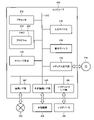
図1は、実施形態に係る加工面判定装置7を備える加工システム1の一例を示す概略構成図である。
図1は、実施形態に係る加工面判定装置7を備える加工システム1の一例を示す概略構成図である。
加工システム1は、判定対象物10を加工する加工部3と、判定対象物10の加工面100を撮像する撮像部4と、学習モデル2を用いて判定対象物10の加工面100の状態を判定する加工面判定装置7と、加工部3、撮像部4及び加工面判定装置7を制御する制御装置5とを備える。また、加工システム1は、付加的な構成として、学習モデル2を生成する機械学習装置6を備える。
判定対象物10は、例えば、金属、樹脂、セラミックス等の任意の材料で形成されて、加工部3による加工対象となる任意の物品である。判定対象物10は、その具体例として、流体機械又は流体機械を構成する流体部品である。なお、判定対象物10の立体形状、表面性状、色、大きさ等は特に限定されない。
加工面100は、例えば、加工部3により判定対象物10が加工されたときの当該判定対象物10の表面である。加工面100は、判定対象物10が有する任意の表面でよく、判定対象物10が有する表面の全体でもよいし、その一部分でもよい。
加工部3は、電力や流体圧等を駆動源として動作する各種のロボットマニュピレータや工作機械の加工機構部等で構成される。加工部3は、制御装置5からの制御指令に基づいて、研磨、研削、切削又は鋳造等の加工工程を実施する。なお、加工部3は、判定対象物10の表面を加工又は形成するものであれば任意の加工工程を実施するものでよく、さらに複数の加工工程を組み合わせて実施するものでもよい。
図1に示す加工システム1では、加工部3は、交換式の砥石が先端に装着されたロボットマニュピレータで構成され、研削工程を実施するものである。また、判定対象物10は、ポンプを構成する流体部品として、複数の羽根を有する羽根車であり、加工面100は、加工部3による研削工程により加工された各羽根の表面である。
撮像部4は、加工面100を撮像するカメラであり、例えば、CMOSセンサやCCDセンサ等のイメージセンサで構成される。撮像部4は、加工面100を撮像可能な所定の位置に取り付けられる。加工部3が、例えば、ロボットマニュピレータで構成される場合には、撮像部4は、ロボットマニュピレータの先端に取り付けられてもよいし、判定対象物10が載置される載置台(可動式も含む)の上方に固定されてもよい。また、加工部3が、例えば、工作機械の加工機構部で構成される場合には、撮像部4は、工作機械の安全カバーの内側に取り付けられてもよいし、工作機械とは別体の作業台の上方に固定されてもよい。
撮像部4は、上記のような所定の位置に取り付けられて、撮像部4の画角内に加工面100が収まるように、位置や向きが調節されている。なお、撮像部4は、図1に示すように、機械学習装置6に接続された撮像部4と、加工面判定装置7に接続された撮像部4とが別々に設けられてもよいし、1つの撮像部4が機械学習装置6及び加工面判定装置7の双方に接続されて共用されてもよい。また、撮像部4は、パン・チルト・ズームの機能を備えるものでもよい。さらに、撮像部4は、加工面100を1台のカメラで撮像するものに限られず、複数台のカメラで撮像するものでもよい。
制御装置5は、例えば、汎用又は専用のコンピュータ(後述の図2参照)やマイクロコントローラ等で構成される制御盤50と、タッチパネルディスプレイ、スイッチ、ボタン等で構成される操作表示盤51とを備える。
制御盤50は、加工部3のアクチュエータやセンサ(いずれも不図示)に接続されて、加工工程を実施するための加工動作パラメータやセンサの検出信号に応じてアクチュエータに制御指令を送ることで、加工部3による加工工程を制御する。制御盤50は、撮像部4に撮像指令を送り、その結果として撮像部4により撮像された撮像画像を受け取る。制御盤50は、撮像画像を判定用画像として加工面判定装置7に送り、その結果として、加工面判定装置7により判定された加工面100の状態を受け取る。なお、制御盤50は、撮像画像を機械学習装置6に送るようにしてもよい。
操作表示盤51は、作業者の操作を受け付けるとともに、各種の情報を表示や音で出力する。
機械学習装置6は、機械学習における学習フェーズの主体として動作する。機械学習装置6は、学習用画像と当該学習用画像に含まれる加工面100の状態を分類した分類結果との相関関係を機械学習させた学習モデル2を生成し、加工面判定装置7に任意の通信網や記録媒体等を介して学習モデル2を提供する。機械学習装置6の詳細は後述する。
加工面判定装置7は、機械学習における推論フェーズの主体として動作する。加工面判定装置7は、機械学習装置6により生成された学習モデル2を用いて、撮像部4により撮像された加工面100の画像を判定用画像として、判定対象物10の加工面100の状態を判定する。加工面判定装置7の詳細は後述する。
なお、加工システム1の各構成要素は、1つの筐体に組み込まれることで、例えば、1つの工作機械として構成されていてもよく、その場合には、機械学習装置6及び加工面判定装置7の少なくとも一方は、制御装置5に組み込まれてもよい。また、加工システム1の各構成要素は、加工部3を備える加工装置と、撮像部4及び加工面判定装置7を備える検査装置とで構成されてもよく、その場合には、制御装置5の機能が加工装置と検査装置とに分散されてもよい。さらに、加工システム1の各構成要素は、無線又は有線のネットワークにより接続されることで、機械学習装置6及び加工面判定装置7の少なくとも一方は、加工部3及び撮像部4が設置された加工現場とは離れた場所に設置されてもよく、その場合には、制御装置5は、加工現場に設置されてもよいし、他の場所に設置されてもよい。
図2は、機械学習装置6及び加工面判定装置7を構成するコンピュータ200の一例を示すハードウエア構成図である。
機械学習装置6及び加工面判定装置7のそれぞれは、汎用又は専用のコンピュータ200により構成される。コンピュータ200は、図2に示すように、その主要な構成要素として、バス210、プロセッサ212、メモリ214、入力デバイス216、表示デバイス218、ストレージ装置220、通信I/F(インターフェース)部222、外部機器I/F部224、I/O(入出力)デバイスI/F部226、及び、メディア入出力部228を備える。なお、上記の構成要素は、コンピュータ200が使用される用途に応じて適宜省略されてもよい。
プロセッサ212は、1つ又は複数の演算処理装置(CPU、MPU、GPU、DSP等)で構成され、コンピュータ200全体を統括する制御部として動作する。メモリ214は、各種のデータ及びプログラム230を記憶し、例えば、メインメモリとして機能する揮発性メモリ(DRAM、SRAM等)と、不揮発性メモリ(ROM、フラッシュメモリ等)とで構成される。
入力デバイス216は、例えば、キーボード、マウス、テンキー、電子ペン等で構成される。表示デバイス218は、例えば、液晶ディスプレイ、有機ELディスプレイ、電子ペーパー、プロジェクタ等で構成される。入力デバイス216及び表示デバイス218は、タッチパネルディスプレイのように、一体的に構成されていてもよい。ストレージ装置220は、例えば、HDD、SSD等で構成され、オペレーティングシステムやプログラム230の実行に必要な各種のデータを記憶する。
通信I/F部222は、インターネットやイントラネット等のネットワーク240に有線又は無線により接続され、所定の通信規格に従って他のコンピュータとの間でデータの送受信を行う。外部機器I/F部224は、プリンタ、スキャナ等の外部機器250に有線又は無線により接続され、所定の通信規格に従って外部機器250との間でデータの送受信を行う。I/OデバイスI/F部226は、各種のセンサ、アクチュエータ等のI/Oデバイス260に接続され、I/Oデバイス260との間で、例えば、センサによる検出信号やアクチュエータへの制御信号等の各種の信号やデータの送受信を行う。メディア入出力部228は、例えば、DVDドライブ、CDドライブ等のドライブ装置で構成され、DVD、CD等のメディア270に対してデータの読み書きを行う。
上記構成を有するコンピュータ200において、プロセッサ212は、プログラム230をメモリ214のワークメモリ領域に呼び出して実行し、バス210を介してコンピュータ200の各部を制御する。なお、プログラム230は、メモリ214の代わりに、ストレージ装置220に記憶されていてもよい。プログラム230は、インストール可能なファイル形式又は実行可能なファイル形式でCD、DVD等の非一時的な記録媒体に記録され、メディア入出力部228を介してコンピュータ200に提供されてもよい。プログラム230は、通信I/F部222を介してネットワーク240経由でダウンロードすることによりコンピュータ200に提供されてもよい。また、コンピュータ200は、プロセッサ212がプログラム230を実行することで実現する各種の機能を、例えば、FPGA、ASIC等のハードウエアで実現するものでもよい。
コンピュータ200は、例えば、据置型コンピュータや携帯型コンピュータで構成され、任意の形態の電子機器である。コンピュータ200は、クライアント型コンピュータでもよいし、サーバ型コンピュータやクラウド型コンピュータでもよい。コンピュータ200は、機械学習装置6及び加工面判定装置7以外の他の装置に適用されてもよい。
(機械学習装置6)
図3は、実施形態に係る機械学習装置6の一例を示すブロック図である。
図3は、実施形態に係る機械学習装置6の一例を示すブロック図である。
機械学習装置6は、学習用データ取得部60、学習用データ記憶部61、機械学習部62、及び、学習済みモデル記憶部63を備える。機械学習装置6は、例えば、図2に示すコンピュータ200で構成される。その場合、学習用データ取得部60は、通信I/F部222又はI/OデバイスI/F部226とプロセッサ212とで構成され、機械学習部62は、プロセッサ212で構成され、学習用データ記憶部61及び学習済みモデル記憶部63は、ストレージ装置220で構成される。
学習用データ取得部60は、各種の外部装置と通信網を介して接続され、入力データ及び出力データが対応付けられた学習用データを取得するインタフェースユニットである。外部装置は、例えば、撮像部4、加工面判定装置7、及び、作業者が使用する作業者用端末8等である。
学習用データ記憶部61は、学習用データ取得部60で取得した学習用データを複数組記憶するデータベースである。なお、学習用データ記憶部61を構成するデータベースの具体的な構成は適宜設計すればよい。
機械学習部62は、学習用データ記憶部61に記憶された学習用データを用いて機械学習を実施する。すなわち、機械学習部62は、学習モデル2に学習用データを複数組入力することで、学習用データに含まれる入力データと出力データとの相関関係を学習モデル2に機械学習させることで、学習モデル2を生成する。
学習済みモデル記憶部63は、機械学習部62により生成された学習モデル2を記憶するデータベースである。学習済みモデル記憶部63に記憶された学習モデル2は、任意の通信網や記録媒体等を介して実システム(例えば、加工面判定装置7)に提供される。なお、学習モデル2は、外部コンピュータ(例えば、サーバ型コンピュータやクラウド型コンピュータ)に提供されて、外部コンピュータの記憶部に記憶されてもよい。また、図3では、学習用データ記憶部61と、学習済みモデル記憶部63とが別々の記憶部として示されているが、これらは単一の記憶部で構成されてもよい。
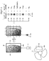
図4は、学習用データの一例を示すデータ構成図である。
学習用データは、学習用画像41を入力データとし、当該学習用画像41に含まれる加工面100の状態を複数の加工状態のいずれかに分類した分類結果を出力データとしてそれぞれ含み、これらの入力データ及び出力データが対応付けられて構成される。
入力データとしての学習用画像41は、撮像部4により判定対象物10の加工面100が撮像された所定の撮像画像領域400を有する撮像画像40を学習用画像領域410に分割することで生成される複数の画像の各々である。
撮像画像40の撮像画像領域400は、撮像部4により撮像された領域であり、撮像部4の画角により定められる。図4に示す撮像画像領域400は、判定対象物10である羽根車が有する1つの羽根の一部分を含むように設定されている。なお、図4に示す撮像画像40には、加工面100だけでなく、背景110についても撮像されているが、背景110が撮像されないように、撮像画像領域400が設定されてもよい。
学習用画像41の学習用画像領域410は、図4に示すように、学習用画像領域410の各々が正方形状となるように、撮像画像40の撮像画像領域400を格子状に分割したものである。なお、学習用画像領域410の画像数、形状、大きさ及び縦横比は、適宜変更してもよく、例えば、長方形状でもよいし、他の形状でもよい。また、撮像画像領域400を学習用画像領域410に分割するときの分割方法は、適宜変更してもよく、例えば、千鳥状に分割してもよいし、他の基準に従って分割してもよい。
出力データとしての分類結果は、教師あり学習において、例えば、教師データや正解ラベルと称される。複数の加工状態として、例えば、「良」及び「不良」の2クラスを採用する場合には、分類結果は、「良」及び「不良」のいずれかで表される。複数の加工状態として、「良」、「可」及び「不良」の3クラスを採用する場合には、分類結果は、「良」、「可」及び「不良」のいずれかで表される。なお、加工面100の状態を分類する際の複数の加工状態は、上記のようなクラスに限定されず、例えば、4クラス以上に分類されてもよいし、他の観点で分類されてもよい。
さらに、学習用画像41に撮像された加工面100以外の背景110を、「判定対象外」というクラスを追加して分類することも可能であり、この場合の分類結果は、上記2クラスの例では、「良」、「不良」及び「判定対象外」のいずれかで表され、上記3クラスの例では、図4に示すように、「良」、「可」「不良」及び「判定対象外」のいずれかで表される。なお、学習用画像41に加工面100及び背景110の両方が撮像されている場合には、例えば、背景110の比率が所定の比率よりも高い場合には「判定対象外」のクラスに分類するようにしてもよいし、「判定対象外」のクラスに常に分類しないようにしてもよい。
学習用データ取得部60は、学習用データを取得する方法として、各種の方法を採用することができる。例えば、学習用データ取得部60は、加工部3により加工工程が実施された後の判定対象物10を撮像部4で撮像された撮像画像40を取得し、その撮像した撮像画像40を分割することで生成される複数の学習用画像41を作業者用端末8の表示画面に表示させる。そして、作業者が、その表示画面上の学習用画像41の各々を視認し、学習用画像41の各々に対するクラスを分類した結果(分類結果)を作業者用端末8により入力操作すると、学習用データ取得部60は、表示画面上の学習用画像41(入力データ)と、入力操作された分類結果(入力データ)とを対応付けることで学習用データを取得する。
したがって、学習用データ取得部60は、1枚の撮像画像40から複数枚の学習用画像41に分割したときの分割数に相当する数の学習用データを取得することができ、さらに上記の作業を繰り返すことで所望の数の学習用データを取得することができる。そのため、学習用データを容易に収集することができる。
図5は、学習モデル2に適用される推論モデル20の一例を示す概略図である。
推論モデル20は、機械学習の具体的な手法として、畳み込みニューラルネットワーク(CNN(Convolutional Neural Network))を採用したものである。推論モデル20は、入力層21、中間層22、及び、出力層23を備える。
入力層21は、入力データとしての学習用画像41に対応する数のニューロンを有し、各ピクセルの画素値が各ニューロンにそれぞれ入力される。
中間層22は、畳み込み層22a、プーリング層22b及び全結合層22cから構成されている。畳み込み層22a及びプーリング層22bは、例えば、交互に複数層設けられている。畳み込み層22a及びプーリング層22bは、入力層21を介して入力された画像から特徴量を抽出する。全結合層22cは、畳み込み層22a及びプーリング層22bにより画像から抽出された特徴量を、例えば、活性化関数によって変換し、特徴ベクトルとして出力する。なお、全結合層22cは、複数層設けられていてもよい。
出力層23は、全結合層22cから出力された特徴ベクトルに基づいて、分類結果を含む出力データを出力する。なお、出力データは、分類結果の他に、例えば、分類結果の信頼度を示すスコアを含むものでもよい。
推論モデル20の各層の間には、層間のニューロンをそれぞれ接続するシナプスが張られており、中間層22の畳み込み層22a及び全結合層22cの各シナプスには、重みが対応付けられている。
機械学習部62は、学習用データを推論モデル20に入力し、学習用画像41と分類結果との相関関係を推論モデル20に機械学習させる。具体的には、機械学習部62は、学習用データを構成する学習用画像41を入力データとして、推論モデル20の入力層21に入力する。なお、機械学習部62は、学習用画像41を入力層21に入力する際の前処理として、所定の画像調整(例えば、画像フォーマット、画像サイズ、画像フィルタ、画像マスク等)を学習用画像41に施してもよい。
機械学習部62は、出力層23から出力された出力データが示す分類結果(推論結果)と、当該学習用データを構成する分類結果(教師データ)とを比較する誤差関数を用いて、誤差関数の評価値が小さくなるように、各シナプスに対応付けられた重みを調整する(バックプロバケーション)ことを反復する。そして、機械学習部62は、上記の一連の処理を所定の回数反復実施することや、誤差関数の評価値が許容値より小さくなること等の所定の学習終了条件が満たされたと判断した場合には、機械学習を終了し、そのときの推論モデル20(各シナプスのそれぞれに対応付けられた全ての重み)を、学習モデル2として学習済みモデル記憶部63に格納する。
(加工面判定装置7)
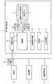
図6は、実施形態に係る加工面判定装置7の一例を示すブロック図である。
図6は、実施形態に係る加工面判定装置7の一例を示すブロック図である。
加工面判定装置7は、画像取得部70、推論部71、学習済みモデル記憶部72、分類結果処理部73、判定部74、及び、出力処理部75を備える。加工面判定装置7は、例えば、図2に示すコンピュータ200で構成される。その場合、画像取得部70は、通信I/F部222又はI/OデバイスI/F部226とプロセッサ212とで構成され、推論部71、分類結果処理部73、判定部74、及び、出力処理部75は、プロセッサ212で構成され、学習済みモデル記憶部72は、ストレージ装置220で構成される。
画像取得部70は、撮像部4に接続されて、撮像部4により判定対象物10の加工面100が撮像された撮像画像を、所定の判定用画像領域を有する判定用画像42として取得するインタフェースユニットである。
推論部71は、判定用画像領域を小画像領域に分割することで判定用画像42から生成される複数の小画像43の各々を学習モデル2に入力することにより、複数の小画像43に対する分類結果を小画像単位で推論する推論処理(後述の図7参照)を行う。その際、推論部71は、複数の小画像43から分割前の判定用画像42を再構築できるように、判定用画像領域420に対する各小画像領域430の位置関係を、例えば、小画像43の付加情報として記録する。なお、推論部71の一部又は全ては、外部コンピュータ(例えば、サーバ型コンピュータやクラウド型コンピュータ)のプロセッサで代用されてもよく、推論部71による推論処理の一部又は全てが、外部コンピュータで実行されてもよい。
学習済みモデル記憶部72は、推論部71の推論処理にて用いられる学習済みの学習モデル2を記憶するデータベースである。なお、学習済みモデル記憶部72に記憶される学習モデル2の数は1つに限定されず、例えば、機械学習の手法、加工部3による加工工程、判定対象物10等の条件が異なる複数の学習済みモデルが記憶され、選択的に利用可能としてもよい。また、学習済みモデル記憶部72は、外部コンピュータ(例えば、サーバ型コンピュータやクラウド型コンピュータ)の記憶部で代用されてもよく、その場合には、推論部71は、当該外部コンピュータにアクセスすることで、上記の推論処理を行ってもよい。
分類結果処理部73は、小画像単位で推論された複数の小画像43に対する分類結果を処理することで処理結果を求める(後述の図8参照)。その際、推論部71が、小画像43に撮像された背景110を判定対象外に分類する分類器として機能する場合には、分類結果処理部73は、複数の小画像43に対する分類結果のうち判定対象外に分類された小画像43以外の小画像43に対する分類結果を処理することで処理結果を求めるようにしてもよい。
分類結果処理部73が複数の小画像43に対する分類結果を処理する方法には、例えば、割合、分布、統計量等を基準とする任意の方法を採用することができる。なお、複数の基準が組み合わせられてもよいし、他の基準が用いられてもよい。
例えば、割合を基準とする場合、分類結果処理部73は、処理結果として、加工面100が撮像された小画像43の全体数に対する、複数の加工状態のうち所定の加工状態に分類された小画像43の合計数の割合を求める。すなわち、分類結果処理部73は、分割前の判定用画像42全体に対して、所定の加工状態に分類された小画像43がどのくらいを占めるのかという観点で加工面100の状態を評価するために上記の割合を求める。
また、分布を基準とする場合、分類結果処理部73は、処理結果として、加工面100が撮像された小画像43の集合に対する、複数の加工状態のうち所定の加工状態に分類された小画像43の集合の分布を求める。すなわち、分類結果処理部73は、分割前の判定用画像42全体に対して、所定の加工状態に分類された小画像43がどのような位置に、どのようなばらつき度合いで存在するのかという観点で加工面100の状態を評価するために上記の分布を求める。
判定部74は、分類結果処理部73により求められた処理結果に基づいて、加工面100の状態を判定する。具体的には、判定部74は、加工面100の状態として、加工面100を加工したときと同一の加工工程を再度行う再加工の要否、加工面100を加工したときと異なる加工工程を行う別加工の要否、加工面100に対して作業者が仕上げ加工を行う仕上げ加工の要否、及び、加工面100のうち再加工、別加工又は仕上げ加工を行う対象とする加工範囲、の少なくとも1つを判定する。
出力処理部75は、判定部74により判定された判定結果を出力するための出力処理を行う。判定結果を出力するための具体的な出力手段は、種々の手段を採用することが可能である。例えば、出力処理部75は、判定結果に応じて、制御盤50を介して再加工や別加工の動作指令を加工部3に送信したり、操作表示盤51や作業者用端末8を介して作業者に仕上げ加工の実施を表示や音で報知したり、加工部3の動作履歴として制御盤50の記憶手段に記憶したりしてもよい。なお、出力処理部75は、判定部74による加工面100の判定結果を出力(送信、報知、記憶)するだけでもよいし、加工面100の判定結果の他に、推論部71による複数の小画像43に対する分類結果、又は、分類結果処理部73による処理結果を出力(送信、報知、記憶)してもよい。
図7は、推論部71による推論処理の一例を示す機能説明図である。
判定用画像42の判定用画像領域420は、撮像部4により撮像された領域であり、撮像部4の画角により定められる。図7に示す判定用画像領域420は、図4に示す撮像画像領域400と同様に、判定対象物10である羽根車が有する1つの羽根の一部分を含むように設定されている。なお、判定用画像領域420は、撮像画像領域400と異なる位置に設定されてもよいし、両者の画像数、形状、大きさ及び縦横比が異なるものでもよい。
小画像43の小画像領域430は、図7に示すように、小画像領域430の各々が正方形状となるように、判定用画像42の判定用画像領域420を格子状に分割したものである。小画像43の小画像領域430は、機械学習装置6にて学習モデル2を生成したときの学習用画像41の学習用画像領域410に相当するものであり、両者の画像数、形状、大きさ及び縦横比は同一又は同程度であることが好ましい。
したがって、小画像領域430の画像数、形状、大きさ及び縦横比が、学習用画像領域410の画像数、形状、大きさ及び縦横比に相当するのであれば、判定用画像領域420を小画像領域430に分割するときの分割方法は、適宜変更してもよく、例えば、千鳥状に分割してもよいし、他の基準に従って分割してもよい。その際、判定用画像領域420を小画像領域430に分割するときの分割方法は、撮像画像領域400を学習用画像領域410に分割するときの分割方法と同一でもよいし、異なるものでもよい。
ここで、学習モデル2は、小画像領域430に相当する学習用画像領域410を有する学習用画像41と当該学習用画像41に含まれる加工面100の状態を複数の加工状態のいずれかに分類した分類結果との相関関係を機械学習装置6にて機械学習させたものである。したがって、推論部71は、小画像43の各々を学習モデル2に入力することにより、小画像単位で、小画像43に撮像された加工面100の状態を複数の加工状態のいずれかに分類する分類器として機能する。複数の加工状態として、2クラス(良、不良)を採用する場合には、推論部71による分類結果は、2クラス(良、不良)で表され、複数の加工状態として、3クラス(良、可、不良)を採用する場合には、推論部71による分類結果は、3クラス(良、可、不良)で表される。
また、学習モデル2は、加工面100又は加工面100以外の背景110の少なくとも一方が撮像された学習用画像41と当該学習用画像41に撮像された加工面100の状態を複数の加工状態のいずれかに分類するとともに当該学習用画像41に撮像された背景110を判定対象外に分類した分類結果との相関関係を機械学習装置6にて機械学習させたものでもよい。この場合、推論部71は、小画像43の各々を学習モデル2に入力することにより、小画像単位で、小画像43に撮像された加工面100の状態を複数の加工状態のいずれかに分類するとともに、小画像43に撮像された背景110を判定対象外に分類する分類器として機能する。分類結果には、複数の加工状態にさらに判定対象外が加わるため、上記の例における推論部71による分類結果は、3クラス(良、不良、判定対象外)、又は、4クラス(良、可、不良、判定対象外)で表される。
なお、推論部71による小画像43に対する分類結果は、各クラスに対するスコア(信頼度)を含むものでもよい。この場合、分類結果が、4クラス(良、可、不良、判定対象外)で表されるものとすると、特定の小画像43に対するクラス毎のスコアは、例えば、「0.02」、「0.10」、「0.95」、「0.31」のように出力される。スコアの利用方法は、任意の方法を採用すればよく、例えば、スコアが最も高いクラス(上記の例では、スコア「0.95」の不良)を小画像43に対する分類結果としてもよいし、所定のクラスのスコアが所定のスコア基準値を超えている場合(上記の例では、「不良」のクラスのスコア「0.95」がスコア基準値「0.80」を超えている場合)、当該クラスを小画像43に対する分類結果としてもよい。
また、推論部71による小画像43に対する分類結果は、学習済みモデル記憶部72や他の記憶装置(不図示)に記憶することが好ましく、過去の分類結果は、例えば、学習済みの学習モデル2の推論精度の更なる向上のため、オンライン学習や再学習に用いられる学習用データとして利用することが可能である。
図8は、割合を基準とする場合の分類結果処理部73及び判定部74の一例を示す機能説明図である。図9は、分布を基準とする場合の分類結果処理部73及び判定部74の一例を示す機能説明図である。
分類結果処理部73及び判定部74の具体例について、1枚の判定用画像42が、図8、図9に示すように、60枚の小画像43に分割された場合を想定して説明する。
図8に示すように、割合を基準とする処理結果を採用する場合、分類結果処理部73は、例えば、「判定対象外」に分類された小画像43の11枚を除いた残りの小画像43、すなわち、加工面100が撮像された小画像43の全体数を49枚と求める。そして、分類結果処理部73は、その全体数(49枚)に対して、「良」に分類された小画像43の合計数(25枚)の第1の割合や、「良」及び「可」に分類された小画像43の合計数(40枚)の第2の割合や、「不良」に分類された小画像43の合計数(11枚)の第3の割合を求める。なお、分類結果処理部73は、第1乃至第3の割合の全てを求めてもよいし、いずれかを求めてよいし、他の計算式に基づく割合を求めてもよい。
判定部74は、上記のように処理結果として求められた割合と、所定の割合基準値とを比較することで、加工面100の状態を判定する。例えば、判定部74は、第1の割合が80%(割合基準値)以上である場合には、再加工「不要」、別加工「不要」、又は、仕上げ加工「不要」と判定してもよい。また、第2の割合が70%以下である場合には、再加工「要」と判定してもよい。さらに、第3の割合が50%以上である場合には、別加工「要」と判定し、第3の割合が10%~50%である場合には、再加工「要」と判定し、第3の割合が5%~10%である場合には、仕上げ加工「要」と判定してもよい。なお、判定部74は、再加工「要」、別加工「要」、又は、仕上げ加工「要」と判定した場合には、例えば、「不良」に分類された小画像43を少なくとも含む範囲を加工範囲として判定してもよい。
図9に示すように、分布を基準とする処理結果を採用する場合、分類結果処理部73は、例えば、「判定対象外」に分類された小画像43の11枚を除いた残りの小画像43、すなわち、加工面100が撮像された小画像43の集合(加工面集合120)を求める。そして、分類結果処理部73は、その加工面集合120に対して、例えば、「不良」に分類された小画像43の集合(不良集合130)の分布を求める。加工面集合120に対する不良集合130の分布としては、例えば、「不良」に分類された9枚の小画像43が隣接するようにして、加工面集合120の特定部分に集まっている第1の分布状況(図9の左側)を表したり、「不良」に分類された3枚の小画像43がそれぞれ隣接することなく、加工面集合120の全体に分散している第2の分布状況(図9の右側)を表したりする。
そして、判定部74は、上記のように処理結果として求められた分布と、所定の分布基準とを比較することで、加工面100の状態を判定する。例えば、判定部74は、加工面集合120に対する不良集合130の分布が第1の分布状況である場合には、再加工「要」、別加工「要」、又は、仕上げ加工「不要」と判定してもよい。また、第2の分布状況である場合には、再加工「不要」、別加工「不要」、又は、仕上げ加工「要」と判定してもよい。なお、判定部74は、再加工「要」、別加工「要」、又は、仕上げ加工「要」と判定した場合には、不良集合130を少なくとも含む範囲を加工範囲として判定してもよい。
なお、推論部71による小画像43に対する分類結果が、各クラスに対するスコアを含む場合には、分類結果処理部73は、当該スコアを利用して処理結果を求めてもよい。例えば、分類結果処理部73は、全体数に対して、「良」のクラスのスコアが所定のスコア基準値(例えば、「0.90」)を超えている小画像43の合計数の割合を求めてもよいし、加工面集合120に対して、「良」のクラスのスコアが所定のスコア基準値(例えば、「0.90」)を超えている小画像43の集合の分布を求めてもよい。
(加工面判定方法)
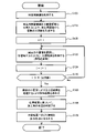
図10は、実施形態に係る加工面判定装置7による加工面判定方法の一例を示すフローチャートである。なお、図10に示す一連の加工面判定方法は、加工面判定装置7により所定のタイミングにて繰り返し実行されるものである。所定のタイミングは、任意のタイミングでよく、例えば、加工部3による加工工程が終了した後でもよいし、加工工程の途中でもよいし、所定の事象発生時(作業者の操作時、生産管理システムからの指示時等)でもよい。以下では、加工面判定方法が、加工部3による加工工程が終了した後に、当該加工工程により加工された判定対象物10に対して実行される場合について説明する。
図10は、実施形態に係る加工面判定装置7による加工面判定方法の一例を示すフローチャートである。なお、図10に示す一連の加工面判定方法は、加工面判定装置7により所定のタイミングにて繰り返し実行されるものである。所定のタイミングは、任意のタイミングでよく、例えば、加工部3による加工工程が終了した後でもよいし、加工工程の途中でもよいし、所定の事象発生時(作業者の操作時、生産管理システムからの指示時等)でもよい。以下では、加工面判定方法が、加工部3による加工工程が終了した後に、当該加工工程により加工された判定対象物10に対して実行される場合について説明する。
まず、ステップ100において、加工部3による加工工程が終了すると、当該加工工程により加工された判定対象物10の加工面100が撮像部4により撮像されて、撮像画像が制御装置5を経由して加工面判定装置7に送られることで、加工面判定装置7の画像取得部70が、当該撮像画像を判定用画像42として取得する。
次に、ステップS110において、推論部71は、判定用画像42に対する前処理として、判定用画像42の判定用画像領域420を小画像領域430に分割することで複数の小画像43を生成する。
次に、ステップS120~S126において、推論部71は、複数の小画像43の分割数をKとして、複数の小画像43に通し番号(1≦n≦K)をそれぞれ割り当てた状態で、変数iを「1」から「K」までインクリメントすることにより、ループ処理を実行する。
具体的には、ステップS120において、推論部71は、変数iを「1」で初期化する。次に、ステップS122において、推論部71は、i番目の小画像43を選択し、学習モデル2の入力層21に入力することにより、当該学習モデル2の出力層23から出力された分類結果を取得する。
次に、ステップS124において、変数iをインクリメントし、ステップS126において、変数iが分割数Kを超えたか否かを判定する。そして、推論部71は、変数iが分割数Kを超えるまで上記ステップS122、S124を繰り返すことで、複数の小画像43に対する分類結果を小画像単位で推論する。
次に、ステップS130において、分類結果処理部73は、分類結果に対する後処理として、小画像単位で推論された複数の小画像43に対する分類結果を処理することで処理結果(例えば、割合、分布、統計量等)を求める。
次に、ステップS140において、判定部74は、分類結果処理部73により求められた処理結果に基づいて、加工面100の状態(例えば、再加工の要否、別加工の要否、仕上げ加工の要否、加工範囲等)を判定する。
次に、ステップS150において、出力処理部75は、判定部74により判定された判定結果に応じた情報を出力手段(例えば、制御装置5、作業者用端末8等)に出力する。そして、図10に示す一連の加工面判定方法を終了する。加工面判定方法において、ステップS100が画像取得工程、ステップS110~S126が推論工程、ステップS130が分類結果処理工程、ステップS140が判定工程、ステップS150が出力処理工程に相当する。
以上のように、本実施形態に係る加工面判定装置7及び加工面判定法によれば、推論部71が、判定用画像領域420を小画像領域430に分割することで判定用画像42から生成される複数の小画像43の各々を学習モデル2に入力することにより、複数の小画像43に対する分類結果を小画像単位で推論し、分類結果処理部73が、小画像単位で推論された複数の小画像43に対する分類結果を処理することで処理結果を求め、判定部74が、処理結果に基づいて加工面100の状態を判定する。
そのため、学習モデル2による分類結果は、判定用画像42が分割された小画像43の各々が入力されることにより小画像単位で推論されるので、1枚の判定用画像を学習モデル2に入力する場合に比べて、機械学習に必要な学習データの収集が容易であるとともに、学習モデル2の精度を向上することができる。そして、学習モデル2による分類結果に対する後処理として、複数の小画像43に対する分類結果を処理することで求められた処理結果に基づいて加工面100の状態が判定される。したがって、判定対象物10が有する加工面100の状態を自動的に判定することができる。
(他の実施形態)
本発明は上述した実施形態に制約されるものではなく、本発明の主旨を逸脱しない範囲内で種々変更して実施することが可能である。そして、それらはすべて、本発明の技術思想に含まれるものである。
本発明は上述した実施形態に制約されるものではなく、本発明の主旨を逸脱しない範囲内で種々変更して実施することが可能である。そして、それらはすべて、本発明の技術思想に含まれるものである。
例えば、上記実施形態では、図7に示す判定用画像領域420は、判定対象物10の羽根車が有する1つの羽根の一部分を判定対象の加工面100として含むように設定されたものである。これに対し、判定用画像領域420は、羽根車全体に拡大することで、羽根車が有する複数の羽根を、判定対象の複数の加工面100として含むように設定されてもよい。すなわち、判定対象物10が、加工部3により異なる加工工程を経てそれぞれ加工された複数の加工面100を有する場合には、判定用画像領域420は、複数の加工面100を含むように設定されてもよい。
この場合、画像取得部70は、複数の加工面100が撮像された判定用画像42を取得する。そして、分類結果処理部73は、複数の小画像43に対する分類結果を加工面毎に処理して処理結果を求め、判定部74は、処理結果に基づいて複数の加工面100の状態を加工面毎に判定する。なお、推論部71は、上記実施形態と同様に、判定用画像42から生成される複数の小画像43の各々を、学習モデル2に入力することにより、複数の小画像43に対する分類結果を小画像単位で推論すればよい。また、判定用画像42における複数の加工面100の境界は、事前に設定されてもよいし、判定用画像42に対する画像処理により設定されてもよいし、分類結果に基づいて設定されてもよい。
また、上記実施形態では、機械学習部62による機械学習の具体的な手法として、CNN(図5参照)を採用した場合について説明したが、機械学習部62は、任意の他の機械学習の手法を採用してもよい。他の機械学習の手法としては、例えば、決定木、回帰木等のツリー型、バギング、ブースティング等のアンサンブル学習、再帰型ニューラルネットワーク、畳み込みニューラルネットワーク等のニューラルネット型(ディープラーニングを含む)、階層型クラスタリング、非階層型クラスタリング、k近傍法、k平均法等のクラスタリング型、主成分分析、因子分析、ロジスティク回帰等の多変量解析、サポートベクターマシン等が挙げられる。
(加工面判定プログラム)
本発明は、図2に示すコンピュータ200を、上記実施形態に係る加工面判定装置7が備える各部として機能させるプログラム(加工面判定プログラム)230の態様で提供することができる。また、本発明は、図2に示すコンピュータ200に、上記実施形態に係る加工面判定方法が備える各工程を実行させるためのプログラム(加工面判定プログラム)230の態様で提供することもできる。
本発明は、図2に示すコンピュータ200を、上記実施形態に係る加工面判定装置7が備える各部として機能させるプログラム(加工面判定プログラム)230の態様で提供することができる。また、本発明は、図2に示すコンピュータ200に、上記実施形態に係る加工面判定方法が備える各工程を実行させるためのプログラム(加工面判定プログラム)230の態様で提供することもできる。
(推論装置、推論方法及び推論プログラム)
本発明は、上記実施形態に係る加工面判定装置7(加工面判定方法又は加工面判定プログラム)の態様によるもののみならず、加工面100の状態を判定するために用いられる推論装置(推論方法又は推論プログラム)の態様で提供することもできる。その場合、推論装置(推論方法又は推論プログラム)としては、メモリと、プロセッサとを含み、このうちのプロセッサが、一連の処理を実行するものとすることができる。当該一連の処理とは、加工面100が撮像された所定の判定用画像領域420を有する判定用画像42を取得する画像取得処理(画像取得工程)と、画像取得処理にて判定用画像42を取得すると、判定用画像領域420を小画像領域430に分割することで判定用画像42から生成される複数の小画像43の各々に対して、加工面100の状態を複数の加工状態のいずれかに分類した分類結果を小画像単位で推論する推論処理(推論工程)と、小画像単位で推論された複数の小画像43に対する分類結果を処理することで処理結果を求める分類結果処理(分類結果処理工程)と、処理結果に基づいて、加工面100の状態を判定する判定処理(判定工程)と、を含む。
本発明は、上記実施形態に係る加工面判定装置7(加工面判定方法又は加工面判定プログラム)の態様によるもののみならず、加工面100の状態を判定するために用いられる推論装置(推論方法又は推論プログラム)の態様で提供することもできる。その場合、推論装置(推論方法又は推論プログラム)としては、メモリと、プロセッサとを含み、このうちのプロセッサが、一連の処理を実行するものとすることができる。当該一連の処理とは、加工面100が撮像された所定の判定用画像領域420を有する判定用画像42を取得する画像取得処理(画像取得工程)と、画像取得処理にて判定用画像42を取得すると、判定用画像領域420を小画像領域430に分割することで判定用画像42から生成される複数の小画像43の各々に対して、加工面100の状態を複数の加工状態のいずれかに分類した分類結果を小画像単位で推論する推論処理(推論工程)と、小画像単位で推論された複数の小画像43に対する分類結果を処理することで処理結果を求める分類結果処理(分類結果処理工程)と、処理結果に基づいて、加工面100の状態を判定する判定処理(判定工程)と、を含む。
推論装置(推論方法又は推論プログラム)の態様で提供することで、加工面判定装置7を実装する場合に比して簡単に種々の装置への適用が可能となる。推論装置(推論方法又は推論プログラム)が加工面100の状態を推論する際、上記実施形態に係る機械学習装置6により生成された学習済みの学習モデル2を用いて、加工面判定装置7の推論部71が実施する推論手法を適用してもよいことは、当業者にとって当然に理解され得るものである。
本発明は、加工面判定装置、加工面判定プログラム、加工面判定方法、及び、加工システムに利用可能である。
1…加工システム、2…学習モデル、3…加工部、4…撮像部、5…制御装置
6…機械学習装置、7…加工面判定装置、8…作業者用端末、10…判定対象物、
20…推論モデル、21…入力層、22…中間層、22a…畳み込み層、
22b…プーリング層、22c…全結合層、23…出力層、
40…撮像画像、41…学習用画像、42…判定用画像、43…小画像、
50…制御盤、51…操作表示盤、
60…学習用データ取得部、61…学習用データ記憶部、
62…機械学習部、63…モデル記憶部、
70…画像取得部、71…推論部、72…モデル記憶部、
73…分類結果処理部、74…判定部、75…出力処理部、
100…加工面、110…背景、120…加工面集合、130…不良集合、
200…コンピュータ
400…撮像画像領域、410…学習用画像領域、
420…判定用画像領域、430…小画像領域
6…機械学習装置、7…加工面判定装置、8…作業者用端末、10…判定対象物、
20…推論モデル、21…入力層、22…中間層、22a…畳み込み層、
22b…プーリング層、22c…全結合層、23…出力層、
40…撮像画像、41…学習用画像、42…判定用画像、43…小画像、
50…制御盤、51…操作表示盤、
60…学習用データ取得部、61…学習用データ記憶部、
62…機械学習部、63…モデル記憶部、
70…画像取得部、71…推論部、72…モデル記憶部、
73…分類結果処理部、74…判定部、75…出力処理部、
100…加工面、110…背景、120…加工面集合、130…不良集合、
200…コンピュータ
400…撮像画像領域、410…学習用画像領域、
420…判定用画像領域、430…小画像領域
Claims (11)
- 判定対象物の加工面の状態を判定する加工面判定装置であって、
前記加工面が撮像された所定の判定用画像領域を有する判定用画像を取得する画像取得部と、
前記判定用画像領域を小画像領域に分割することで前記判定用画像から生成される複数の小画像の各々を、前記小画像領域に相当する学習用画像領域を有する学習用画像と当該学習用画像に含まれる前記加工面の状態を複数の加工状態のいずれかに分類した分類結果との相関関係を機械学習させた学習モデルに入力することにより、複数の前記小画像に対する前記分類結果を前記小画像単位で推論する推論部と、
前記小画像単位で推論された複数の前記小画像に対する前記分類結果を処理することで処理結果を求める分類結果処理部と、
前記処理結果に基づいて、前記加工面の状態を判定する判定部と、を備える、
加工面判定装置。 - 前記分類結果処理部は、
前記処理結果として、前記加工面が撮像された前記小画像の全体数に対する、複数の前記加工状態のうち所定の加工状態に分類された前記小画像の合計数の割合を求める、
請求項1に記載の加工面判定装置。 - 前記分類結果処理部は、
前記処理結果として、前記加工面が撮像された前記小画像の集合に対する、複数の前記加工状態のうち所定の加工状態に分類された前記小画像の集合の分布を求める、
請求項1に記載の加工面判定装置。 - 前記画像取得部は、
複数の前記加工面が撮像された前記判定用画像を取得し、
前記分類結果処理部は、
複数の前記小画像に対する前記分類結果を前記加工面毎に処理して処理結果を求め、
前記判定部は、前記処理結果に基づいて複数の前記加工面の状態を前記加工面毎に判定する、
請求項1乃至請求項3のいずれか一項に記載の加工面判定装置。 - 前記推論部は、
複数の前記小画像の各々を、前記加工面又は前記加工面以外の背景の少なくとも一方が撮像された前記学習用画像と当該学習用画像に撮像された前記加工面の状態を複数の加工状態のいずれかに分類するとともに当該学習用画像に撮像された前記背景を判定対象外に分類した分類結果との相関関係を機械学習させた学習モデルに入力することにより、複数の前記小画像に対する前記分類結果を前記小画像単位で推論し、
前記分類結果処理部は、
前記小画像単位で推論された複数の前記小画像に対する前記分類結果のうち前記判定対象外に分類された前記小画像以外の前記小画像に対する前記分類結果を処理することで前記処理結果を求める、
請求項1乃至請求項4のいずれか一項に記載の加工面判定装置。 - 前記判定部は、
前記加工面の状態として、
前記加工面を加工したときと同一の加工工程を再度行う再加工の要否、
前記加工面を加工したときと異なる加工工程を行う別加工の要否、
前記加工面に対して作業者が仕上げ加工を行う仕上げ加工の要否、及び、
前記加工面のうち前記再加工、前記別加工又は前記仕上げ加工を行う対象とする加工範囲、
の少なくとも1つを判定する、
請求項1乃至請求項5のいずれか一項に記載の加工面判定装置。 - 前記加工面は、研磨工程、研削工程、切削工程又は鋳造工程により前記判定対象物が加工されたときの当該判定対象物の表面である、
請求項1乃至請求項6のいずれか一項に記載の加工面判定装置。 - 前記判定対象物は、流体機械又は前記流体機械を構成する流体部品である、
請求項1乃至請求項7のいずれか一項に記載の加工面判定装置。 - コンピュータを、請求項1乃至請求項8のいずれか一項に記載の加工面判定装置として機能させる、
加工面判定プログラム。 - 判定対象物の加工面を判定する加工面判定方法であって、
前記加工面が撮像された所定の判定用画像領域を有する判定用画像を取得する画像取得工程と、
前記判定用画像領域を小画像領域に分割することで前記判定用画像から生成される複数の小画像の各々を、前記小画像領域に相当する学習用画像領域を有する学習用画像と当該学習用画像に含まれる前記加工面の状態を複数の加工状態のいずれかに分類した分類結果との相関関係を機械学習させた学習モデルに入力することにより、複数の前記小画像に対する前記分類結果を前記小画像単位で推論する推論工程と、
前記小画像単位で推論された複数の前記小画像に対する前記分類結果を処理することで処理結果を求める分類結果処理工程と、
前記処理結果に基づいて、前記加工面の状態を判定する判定工程と、を備える、
加工面判定方法。 - 請求項1乃至請求項8のいずれか一項に記載の加工面判定装置と、
前記判定対象物を加工する加工部と、
前記判定対象物の加工面を撮像する撮像部と、
前記加工面判定装置、前記加工部及び前記撮像部を制御する制御部と、を備える、
加工システム。
Priority Applications (1)
| Application Number | Priority Date | Filing Date | Title |
|---|---|---|---|
| CN202180071197.6A CN116324334A (zh) | 2020-10-23 | 2021-07-13 | 加工面判定装置、加工面判定程序、加工面判定方法、以及加工系统 |
Applications Claiming Priority (2)
| Application Number | Priority Date | Filing Date | Title |
|---|---|---|---|
| JP2020-178367 | 2020-10-23 | ||
| JP2020178367A JP7450517B2 (ja) | 2020-10-23 | 2020-10-23 | 加工面判定装置、加工面判定プログラム、加工面判定方法、及び、加工システム |
Publications (1)
| Publication Number | Publication Date |
|---|---|
| WO2022085253A1 true WO2022085253A1 (ja) | 2022-04-28 |
Family
ID=81290407
Family Applications (1)
| Application Number | Title | Priority Date | Filing Date |
|---|---|---|---|
| PCT/JP2021/026260 Ceased WO2022085253A1 (ja) | 2020-10-23 | 2021-07-13 | 加工面判定装置、加工面判定プログラム、加工面判定方法、及び、加工システム |
Country Status (3)
| Country | Link |
|---|---|
| JP (1) | JP7450517B2 (ja) |
| CN (1) | CN116324334A (ja) |
| WO (1) | WO2022085253A1 (ja) |
Families Citing this family (3)
| Publication number | Priority date | Publication date | Assignee | Title |
|---|---|---|---|---|
| US12149110B2 (en) * | 2021-10-14 | 2024-11-19 | Arm Limited | Battery cell monitoring systems, battery packs, and methods of operation of the same |
| JP7582250B2 (ja) * | 2022-05-13 | 2024-11-13 | Jfeスチール株式会社 | 画像解析装置、機械の評価装置、及び機械の診断方法 |
| KR102883296B1 (ko) * | 2022-06-07 | 2025-11-14 | 주식회사 채움아이티 | 인공지능을 이용한 소성가공 분야의 툴 상태 및 절단품 검사 장치 및 방법 |
Citations (4)
| Publication number | Priority date | Publication date | Assignee | Title |
|---|---|---|---|---|
| WO2018235266A1 (ja) * | 2017-06-23 | 2018-12-27 | 株式会社Rist | 検査装置、検査方法及び検査プログラム |
| JP2019056668A (ja) * | 2017-09-22 | 2019-04-11 | エヌ・ティ・ティ・コムウェア株式会社 | 情報処理装置、情報処理システム、情報処理方法、及び情報処理プログラム |
| CN109632817A (zh) * | 2019-01-15 | 2019-04-16 | 天津大学 | 一种基于准直激光束的织物织造在线疵点检测方法 |
| JP2019211415A (ja) * | 2018-06-08 | 2019-12-12 | アズビル株式会社 | 外観検査装置および方法 |
Family Cites Families (6)
| Publication number | Priority date | Publication date | Assignee | Title |
|---|---|---|---|---|
| JP5658873B2 (ja) * | 2009-11-13 | 2015-01-28 | オリンパス株式会社 | 画像処理装置、電子機器、内視鏡システム及びプログラム |
| JP6359350B2 (ja) * | 2014-06-13 | 2018-07-18 | 株式会社キーエンス | 三次元形状測定装置、測定データ処理ユニット、測定データ処理方法、及びコンピュータプログラム |
| DE102016212486A1 (de) * | 2016-07-08 | 2018-01-11 | Fraunhofer-Gesellschaft zur Förderung der angewandten Forschung e.V. | Verfahren und Einrichtung zur Kategorisierung einer Bruchfläche eines Bauteils |
| JP6530779B2 (ja) * | 2017-04-20 | 2019-06-12 | ファナック株式会社 | 加工不良要因推定装置 |
| JP7062474B2 (ja) * | 2018-03-14 | 2022-05-06 | 株式会社Nttファシリティーズ | 劣化状況識別装置、劣化状況識別方法及びプログラム |
| CN109636772A (zh) * | 2018-10-25 | 2019-04-16 | 同济大学 | 基于深度学习的不规则形状金属加工表面的缺陷检测方法 |
-
2020
- 2020-10-23 JP JP2020178367A patent/JP7450517B2/ja active Active
-
2021
- 2021-07-13 WO PCT/JP2021/026260 patent/WO2022085253A1/ja not_active Ceased
- 2021-07-13 CN CN202180071197.6A patent/CN116324334A/zh active Pending
Patent Citations (4)
| Publication number | Priority date | Publication date | Assignee | Title |
|---|---|---|---|---|
| WO2018235266A1 (ja) * | 2017-06-23 | 2018-12-27 | 株式会社Rist | 検査装置、検査方法及び検査プログラム |
| JP2019056668A (ja) * | 2017-09-22 | 2019-04-11 | エヌ・ティ・ティ・コムウェア株式会社 | 情報処理装置、情報処理システム、情報処理方法、及び情報処理プログラム |
| JP2019211415A (ja) * | 2018-06-08 | 2019-12-12 | アズビル株式会社 | 外観検査装置および方法 |
| CN109632817A (zh) * | 2019-01-15 | 2019-04-16 | 天津大学 | 一种基于准直激光束的织物织造在线疵点检测方法 |
Also Published As
| Publication number | Publication date |
|---|---|
| JP7450517B2 (ja) | 2024-03-15 |
| JP2022069275A (ja) | 2022-05-11 |
| CN116324334A (zh) | 2023-06-23 |
Similar Documents
| Publication | Publication Date | Title |
|---|---|---|
| Jin et al. | Autonomous in-situ correction of fused deposition modeling printers using computer vision and deep learning | |
| Rachmawati et al. | Digital twin-enabled 3D printer fault detection for smart additive manufacturing | |
| EP3921711B1 (en) | Systems, methods, and media for artificial intelligence process control in additive manufacturing | |
| US11511420B2 (en) | Machine learning device, robot system, and machine learning method for learning operation program of robot | |
| WO2022085253A1 (ja) | 加工面判定装置、加工面判定プログラム、加工面判定方法、及び、加工システム | |
| KR20220117194A (ko) | 추론 연산 장치, 모델 훈련 장치, 및 추론 연산 시스템 | |
| CN114897102B (zh) | 一种工业机器人故障诊断方法、系统、设备与存储介质 | |
| JP6993483B2 (ja) | ロボット装置の異常を検出する方法 | |
| JP2019162712A (ja) | 制御装置、機械学習装置及びシステム | |
| US11035666B2 (en) | Inspection-guided critical site selection for critical dimension measurement | |
| CN113537277A (zh) | 确定分类的解释 | |
| CN114730407A (zh) | 使用神经网络对工作环境中的人类行为进行建模 | |
| US20230342908A1 (en) | Distortion prediction for additive manufacturing using image analysis | |
| CN111831703A (zh) | 显示方法、用户接口部、显示装置以及检查装置 | |
| Hong et al. | Hyperparameter optimization for convolutional neural network by opposite-based particle swarm optimization and an empirical study of photomask defect classification | |
| JP6542738B2 (ja) | 対象物の出荷時検査情報と稼働時アラーム情報の相関関係を学習する機械学習装置および機械学習方法 | |
| CN116664934B (zh) | 无人机镜头处理方法、装置、计算机设备和存储介质 | |
| JP7531412B2 (ja) | 加工面判定装置、加工面判定プログラム、加工面判定方法、加工システム、推論装置、及び、機械学習装置 | |
| JP7712151B2 (ja) | 肌落ち予測装置、機械学習装置、肌落ち予測方法、及び、機械学習方法 | |
| JP7799033B2 (ja) | 機械学習装置、特徴抽出装置、及び制御装置 | |
| WO2021124417A1 (ja) | 前景抽出装置、前景抽出方法、及び、記録媒体 | |
| JP6829271B2 (ja) | 測定動作パラメータ調整装置、機械学習装置及びシステム | |
| TWI768092B (zh) | 用於臨界尺寸量測之檢測導引臨界位點選擇 | |
| JP2024060240A (ja) | 情報処理装置、情報処理方法およびプログラム | |
| Ju et al. | Comparison of deep learning models for 3D food printing monitoring system |
Legal Events
| Date | Code | Title | Description |
|---|---|---|---|
| 121 | Ep: the epo has been informed by wipo that ep was designated in this application |
Ref document number: 21882394 Country of ref document: EP Kind code of ref document: A1 |
|
| NENP | Non-entry into the national phase |
Ref country code: DE |
|
| 122 | Ep: pct application non-entry in european phase |
Ref document number: 21882394 Country of ref document: EP Kind code of ref document: A1 |