WO2022085252A1 - Terminal, base station, transmitting method, and receiving method - Google Patents
Terminal, base station, transmitting method, and receiving method Download PDFInfo
- Publication number
- WO2022085252A1 WO2022085252A1 PCT/JP2021/026259 JP2021026259W WO2022085252A1 WO 2022085252 A1 WO2022085252 A1 WO 2022085252A1 JP 2021026259 W JP2021026259 W JP 2021026259W WO 2022085252 A1 WO2022085252 A1 WO 2022085252A1
- Authority
- WO
- WIPO (PCT)
- Prior art keywords
- terminal
- offset
- timing
- base station
- transmission
- Prior art date
Links
- 238000000034 method Methods 0.000 title claims description 131
- 230000005540 biological transmission Effects 0.000 claims abstract description 230
- 230000008569 process Effects 0.000 claims description 52
- 238000011144 upstream manufacturing Methods 0.000 claims description 3
- 238000004891 communication Methods 0.000 description 69
- 230000006870 function Effects 0.000 description 42
- 238000012545 processing Methods 0.000 description 35
- 238000010586 diagram Methods 0.000 description 26
- 230000008859 change Effects 0.000 description 20
- 238000001514 detection method Methods 0.000 description 15
- 101000741965 Homo sapiens Inactive tyrosine-protein kinase PRAG1 Proteins 0.000 description 14
- 102100038659 Inactive tyrosine-protein kinase PRAG1 Human genes 0.000 description 14
- 239000002245 particle Substances 0.000 description 14
- 238000005516 engineering process Methods 0.000 description 13
- 238000007726 management method Methods 0.000 description 13
- 230000007958 sleep Effects 0.000 description 13
- 238000006243 chemical reaction Methods 0.000 description 10
- 230000011664 signaling Effects 0.000 description 10
- 230000004044 response Effects 0.000 description 9
- 230000001413 cellular effect Effects 0.000 description 7
- 238000013507 mapping Methods 0.000 description 7
- 230000008054 signal transmission Effects 0.000 description 6
- 102100039292 Cbp/p300-interacting transactivator 1 Human genes 0.000 description 4
- 101000888413 Homo sapiens Cbp/p300-interacting transactivator 1 Proteins 0.000 description 4
- 239000011362 coarse particle Substances 0.000 description 4
- 238000012937 correction Methods 0.000 description 4
- 230000006872 improvement Effects 0.000 description 4
- 230000002618 waking effect Effects 0.000 description 4
- 238000004364 calculation method Methods 0.000 description 3
- 125000004122 cyclic group Chemical group 0.000 description 3
- 230000000694 effects Effects 0.000 description 3
- 239000010419 fine particle Substances 0.000 description 3
- 238000000926 separation method Methods 0.000 description 3
- 102100022734 Acyl carrier protein, mitochondrial Human genes 0.000 description 2
- 101000678845 Homo sapiens Acyl carrier protein, mitochondrial Proteins 0.000 description 2
- 230000008901 benefit Effects 0.000 description 2
- 238000004590 computer program Methods 0.000 description 2
- 230000001934 delay Effects 0.000 description 2
- 238000009826 distribution Methods 0.000 description 2
- 238000004519 manufacturing process Methods 0.000 description 2
- 238000005259 measurement Methods 0.000 description 2
- 238000002360 preparation method Methods 0.000 description 2
- 238000013468 resource allocation Methods 0.000 description 2
- 230000007704 transition Effects 0.000 description 2
- 238000012935 Averaging Methods 0.000 description 1
- 101100150274 Caenorhabditis elegans srb-2 gene Proteins 0.000 description 1
- 241000854291 Dianthus carthusianorum Species 0.000 description 1
- 101001055444 Homo sapiens Mediator of RNA polymerase II transcription subunit 20 Proteins 0.000 description 1
- 102100026165 Mediator of RNA polymerase II transcription subunit 20 Human genes 0.000 description 1
- 230000001133 acceleration Effects 0.000 description 1
- 230000006978 adaptation Effects 0.000 description 1
- 230000002411 adverse Effects 0.000 description 1
- 230000003321 amplification Effects 0.000 description 1
- 230000003190 augmentative effect Effects 0.000 description 1
- 230000003139 buffering effect Effects 0.000 description 1
- 239000000969 carrier Substances 0.000 description 1
- 238000007906 compression Methods 0.000 description 1
- 230000006835 compression Effects 0.000 description 1
- 230000001186 cumulative effect Effects 0.000 description 1
- 238000013523 data management Methods 0.000 description 1
- 230000003111 delayed effect Effects 0.000 description 1
- 238000011161 development Methods 0.000 description 1
- 239000003814 drug Substances 0.000 description 1
- 238000005538 encapsulation Methods 0.000 description 1
- 238000001914 filtration Methods 0.000 description 1
- 238000009472 formulation Methods 0.000 description 1
- 230000036541 health Effects 0.000 description 1
- 238000009776 industrial production Methods 0.000 description 1
- 238000007689 inspection Methods 0.000 description 1
- 230000010354 integration Effects 0.000 description 1
- 230000003993 interaction Effects 0.000 description 1
- 238000012423 maintenance Methods 0.000 description 1
- 230000007246 mechanism Effects 0.000 description 1
- 239000000203 mixture Substances 0.000 description 1
- 238000012544 monitoring process Methods 0.000 description 1
- 238000003199 nucleic acid amplification method Methods 0.000 description 1
- 230000000737 periodic effect Effects 0.000 description 1
- 238000011084 recovery Methods 0.000 description 1
- 239000004065 semiconductor Substances 0.000 description 1
- 238000001356 surgical procedure Methods 0.000 description 1
- 238000012384 transportation and delivery Methods 0.000 description 1
- 230000001960 triggered effect Effects 0.000 description 1
- 238000012795 verification Methods 0.000 description 1
Images


Classifications
-
- H—ELECTRICITY
- H04—ELECTRIC COMMUNICATION TECHNIQUE
- H04W—WIRELESS COMMUNICATION NETWORKS
- H04W72/00—Local resource management
- H04W72/12—Wireless traffic scheduling
- H04W72/1263—Mapping of traffic onto schedule, e.g. scheduled allocation or multiplexing of flows
- H04W72/1268—Mapping of traffic onto schedule, e.g. scheduled allocation or multiplexing of flows of uplink data flows
-
- H—ELECTRICITY
- H04—ELECTRIC COMMUNICATION TECHNIQUE
- H04W—WIRELESS COMMUNICATION NETWORKS
- H04W56/00—Synchronisation arrangements
- H04W56/004—Synchronisation arrangements compensating for timing error of reception due to propagation delay
- H04W56/0045—Synchronisation arrangements compensating for timing error of reception due to propagation delay compensating for timing error by altering transmission time
-
- H—ELECTRICITY
- H04—ELECTRIC COMMUNICATION TECHNIQUE
- H04L—TRANSMISSION OF DIGITAL INFORMATION, e.g. TELEGRAPHIC COMMUNICATION
- H04L5/00—Arrangements affording multiple use of the transmission path
- H04L5/003—Arrangements for allocating sub-channels of the transmission path
- H04L5/0053—Allocation of signaling, i.e. of overhead other than pilot signals
-
- H—ELECTRICITY
- H04—ELECTRIC COMMUNICATION TECHNIQUE
- H04L—TRANSMISSION OF DIGITAL INFORMATION, e.g. TELEGRAPHIC COMMUNICATION
- H04L5/00—Arrangements affording multiple use of the transmission path
- H04L5/0091—Signaling for the administration of the divided path
- H04L5/0094—Indication of how sub-channels of the path are allocated
-
- H—ELECTRICITY
- H04—ELECTRIC COMMUNICATION TECHNIQUE
- H04W—WIRELESS COMMUNICATION NETWORKS
- H04W56/00—Synchronisation arrangements
- H04W56/004—Synchronisation arrangements compensating for timing error of reception due to propagation delay
- H04W56/005—Synchronisation arrangements compensating for timing error of reception due to propagation delay compensating for timing error by adjustment in the receiver
-
- H—ELECTRICITY
- H04—ELECTRIC COMMUNICATION TECHNIQUE
- H04W—WIRELESS COMMUNICATION NETWORKS
- H04W72/00—Local resource management
- H04W72/04—Wireless resource allocation
- H04W72/11—Semi-persistent scheduling
-
- H—ELECTRICITY
- H04—ELECTRIC COMMUNICATION TECHNIQUE
- H04W—WIRELESS COMMUNICATION NETWORKS
- H04W72/00—Local resource management
- H04W72/20—Control channels or signalling for resource management
- H04W72/23—Control channels or signalling for resource management in the downlink direction of a wireless link, i.e. towards a terminal
- H04W72/232—Control channels or signalling for resource management in the downlink direction of a wireless link, i.e. towards a terminal the control data signalling from the physical layer, e.g. DCI signalling
-
- H—ELECTRICITY
- H04—ELECTRIC COMMUNICATION TECHNIQUE
- H04W—WIRELESS COMMUNICATION NETWORKS
- H04W72/00—Local resource management
- H04W72/20—Control channels or signalling for resource management
- H04W72/23—Control channels or signalling for resource management in the downlink direction of a wireless link, i.e. towards a terminal
-
- H—ELECTRICITY
- H04—ELECTRIC COMMUNICATION TECHNIQUE
- H04W—WIRELESS COMMUNICATION NETWORKS
- H04W84/00—Network topologies
- H04W84/02—Hierarchically pre-organised networks, e.g. paging networks, cellular networks, WLAN [Wireless Local Area Network] or WLL [Wireless Local Loop]
- H04W84/04—Large scale networks; Deep hierarchical networks
- H04W84/06—Airborne or Satellite Networks
Definitions
- This disclosure relates to terminals, base stations, transmission methods and reception methods.
- NR New Radio access technology
- the non-limiting embodiment of the present disclosure contributes to the provision of a terminal, a base station, a transmission method, and a reception method capable of realizing appropriate timing control according to the propagation delay between the terminal and the base station.
- the terminal controls the uplink transmission timing by using either the first offset or the second offset shorter than the first offset based on the information regarding the control signal for scheduling.
- a control circuit for performing uplink transmission and a transmission circuit for performing uplink transmission based on the control of the uplink transmission timing are provided.
- Diagram showing an example of a 4-step random access procedure A diagram showing an example of timing adjustment based on the position information of the terminal and the orbit information of the satellite.
- Diagram showing an example of transmission slot timing Block diagram showing a partial configuration example of a terminal
- Block diagram showing a partial configuration example of a base station Block diagram showing an example of the configuration of the terminal according to the first embodiment
- Block diagram showing an example of the configuration of the base station according to the first embodiment
- FIG. 1 Figure showing an example of timing adjustment using information including K adj, UE
- FIG. 2 The figure which shows an example of the sequence chart about the timing control in Embodiment 2.
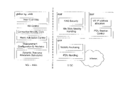
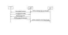
- Illustration of an exemplary architecture of a 3GPP NR system Schematic diagram showing functional separation between NG-RAN and 5GC Sequence diagram of RRC connection setup / reset procedure Use scenarios for large-capacity high-speed communication (eMBB: enhancedMobile BroadBand), multiple simultaneous connection machine type communication (mMTC: massiveMachineTypeCommunications), and high-reliability / ultra-low latency communication (URLLC: UltraReliableandLowLatencyCommunications).
- eMBB enhancedMobile BroadBand
- mMTC massiveMachineTypeCommunications
- URLLC UltraReliableandLowLatencyCommunications
- Non-Terrestrial Network Release 15 (Rel.15), a new radio access technology (NR), is specified as a radio access technology for terrestrial networks.
- NR is being considered for extension to non-terrestrial networks (NTN: Non-Terrestrial Network) such as communication using satellites and / or high-altitude platform stations (HAPS) (NTN: Non-Terrestrial Network) (Non-Terrestrial Network).
- NTN Non-Terrestrial Network
- HAPS high-altitude platform stations
- Non-Patent Document 1 In the NTN environment, for example, a terminal and a base station perform wireless communication via a satellite.
- the wireless link between the terminal and the satellite may be described as a "service link”
- the wireless link between the satellite and the base station may be described as a "feeder link”.
- a satellite coverage area for a ground terminal or an aircraft terminal is formed by a beam from the satellite.
- the round-trip time of radio wave propagation between the terminal and the satellite is determined by the altitude of the satellite (for example, up to about 36000 km) and / or the angle seen from the terminal, that is, the positional relationship between the satellite and the terminal.
- the base station is located on the ground GW (Gateway)
- the round-trip time of radio wave propagation between the base station and the terminal is the sum of the round-trip time of radio wave propagation between the satellite and the ground GW.
- Non-Patent Document 1 the round-trip time (RTT: Round Trip Time) of radio wave propagation between a base station and a terminal takes about 540 ms at the maximum. Further, Non-Patent Document 1 also describes that a maximum delay difference of about 10 ms occurs depending on the location of the terminal in the beam (inside the cell). The maximum delay difference is, for example, the round-trip time between the terminal farthest from the satellite and the satellite and the round-trip time between the terminal closest to the satellite and the satellite in the beam (inside the cell). Shows the difference with.
- RTT Round Trip Time
- Random access procedure In 5G NR, the terminal performs transmission using a random access channel for initial access and data transmission request.
- the random access procedure is carried out by 4-step random access (also called 4-step RACH (Random Access Channel) or 4-Step CBRA (Contention Based Random Access)).
- FIG. 1 is a diagram showing an example of a four-step random access procedure.
- the terminal UE: User Equipment
- Send to. MSG1 transmission in the terminal is carried out at the transmission timing (slot timing or RACH Occasion) notified from the base station for each cell.
- transmitting a PRACH signal for example, a Preamble signal
- PRACH transmission for example, a Preamble signal
- PRACH transmission for example, a Preamble signal
- receiving a PRACH signal may be described as "PRACH reception” or “PRACH reception”.
- transmission / reception of signals of other channels may be abbreviated.
- the base station receives and decodes the MSG1 and, in the second stage transmission (MSG2), sends the RA response (Random Access response (RAR)) to the PRACH Preamble signal and the scheduling information including the uplink transmission timing of the MSG3 to the terminal. Notice.
- the terminal receives and decodes MSG2, and in the third stage transmission (MSG3), using the scheduling information instructed by MSG2, information related to the terminal (for example, terminal ID, etc.) and other information for establishing a connection, etc. Is notified to the base station.
- MSG3 is notified in, for example, PUSCH (Physical Uplink Shared Channel).
- the information notified by MSG3 may be referred to as RRC (Radio Resource Control) connection request information.
- the base station receives and decodes MSG3 and notifies the Connection establishment response etc. in the fourth stage transmission (MSG4).
- the transmission timing of terminals is controlled so that signals from different terminals in the cell are settled within a certain time at the base station. For example, within a certain period of time is within the CP (Cyclic Prefix) of an OFDM (Orthogonal Frequency Division Multiplexing) signal or a DFT-S-OFDM (Discrete Fourier Transform-Spread-OFDM) signal.
- CP Cyclic Prefix
- OFDM Orthogonal Frequency Division Multiplexing
- DFT-S-OFDM Discrete Fourier Transform-Spread-OFDM
- the transmission of the MSG1 of the terminal is carried out at the transmission timing (RACH Occasion) notified from the base station for each cell.
- the terminal determines the transmission timing based on the reception timing of the synchronization signal called SSB (SS (Synchronization Signal) / PBCH (Physical Broadcast channel) Block) transmitted from the base station on the downlink. Therefore, the reception timing at the base station deviates from the reception timing assumed at the base station according to the propagation delay between the base station and the terminal.
- the reception timing assumed in the base station is, for example, a reception timing determined based on the transmission timing (RACH Occasion) notified by the base station for each cell.
- the base station transmits information for correcting (adjusting) the timing to the terminal in MSG2.
- Information for correcting (adjusting) the timing may be referred to as a TA (Timing Advance) command (for example, Non-Patent Document 2).
- the terminal corrects the transmission timing after MSG3 based on the TA command included in MSG2.
- the base station transmits a TA command to the terminal when it detects a deviation in reception timing in the transmission / reception of signals after MSG3.
- the communication between the base station and the terminal is a long-distance communication, so the propagation delay between the base station and the terminal is larger than that of the terrestrial cellular system, and the difference in the propagation delay between the terminals. Is big.
- the difference in propagation delay between terminals is, for example, the difference between the propagation delay between a certain base station A and a certain terminal a and the propagation delay between the base station A and a terminal b different from the terminal a. Corresponds to.
- the reception timing of PRACH transmitted from different terminals at the base station differs greatly, and reception at the base station becomes complicated.
- the TA command specified in Rel.15 may not be able to correct the propagation delay that occurs in the NTN environment. Further, when the range (range) of the value of the TA command is widened in order to correct the large propagation delay, the amount of information (for example, the number of bits) required for the notification of the TA command increases.
- the terminal is a terminal and a satellite estimated by using the position information of the terminal acquired by GNSS (Global Navigation Satellite System) and the position information of the satellite obtained from the orbit information (satellite ephemeris) of the satellite. It is considered that the propagation delay is calculated based on the distance between the satellite and the terminal autonomously adjusts the timing.
- GNSS Global Navigation Satellite System
- the propagation delay is calculated based on the distance between the satellite and the terminal autonomously adjusts the timing.
- FIG. 2 is a diagram showing an example of timing adjustment based on the position information (UE location information) of the terminal and the orbit information (satellite ephemeris) of the satellite.
- FIG. 2 illustrates the downlink (DL) transmission slot and uplink (UL) reception slot of the base station (gNB), and the DL reception slot and UL transmission slot of the terminal (UE).
- the horizontal axis of FIG. 2 indicates a time axis.
- the propagation delay from the transmission timing of a certain signal at the base station to the reception timing of the signal at the terminal is the feeder link propagation delay (Feeder link delay) and the service link propagation delay (Service link delay). Is shown to be represented by. Further, FIG. 2 shows that the terminal adjusts the signal transmission timing by using the TA determined based on the position information of the terminal and the orbit information of the satellite. In FIG. 2, TA corresponds to, for example, twice the propagation delay of the service link.
- the delay between the terminal and the satellite is corrected, but with the base station located on the ground GW (Gateway). Delays to and from satellites (ie, feeder links) are not compensated. Also, in an environment where the satellite and the terminal are out of line (Non Line-of-Sight: NLOS), the propagation delay calculated using the position information is the actual reflection and / or diffraction that occurs in the out-of-line environment. It may be different from the propagation delay.
- the timing of the transmission slot is specified in Rel.15.
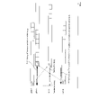
- FIG. 3 is a diagram showing an example of transmission slot timing.
- FIG. 3 shows an example of the transmission slot timing in the ground cellular specified by Rel.15 and an example of the transmission slot timing examined by NTN.
- FIG. 3 illustrates the DL transmission slot and UL reception slot of the base station (gNB), and the DL reception slot and UL transmission slot of the terminal (UE).
- the horizontal axis in FIG. 3 indicates a time axis.
- a signal including DCI Downlink Control Information
- the PUSCH signal is transmitted in the n + K second slot. It is transmitted from the terminal to the base station.
- NTN may abbreviate the offset K offset, cell (K offset ) for correcting the propagation delay longer than that of the ground cellular with respect to the transmission slot timing regulation of Rel.15. ) Is being considered.
- K offset is notified cell by cell.
- the round-trip propagation delay (RTT) between the terminal and the satellite differs depending on the position of the terminal in the cell, even if an offset for correcting the propagation delay longer than that of the ground cellular is provided, it depends on the terminal. May not be in time for transmission, or may wait for a long time.
- timing control using TA and transmission slot control are performed in an environment where the propagation delay between the terminal and the base station increases. Considering both, appropriate timing control according to the propagation delay between the terminal and the base station is realized.
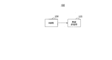
- the communication system includes a terminal 100 (corresponding to a transmitting device) and a base station 200 (corresponding to a receiving device).
- FIG. 4 is a block diagram showing a configuration example of a part of the terminal 100.
- the control unit 109 is based on the first information regarding the control of the signal transmission timing in the signal transmission unit and the second information regarding the control of the transmission timing in a unit finer than the transmission unit. And control the transmission timing.
- the wireless transmission unit 105 transmits a signal based on the control of the transmission timing by the control unit 109.
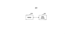
- FIG. 5 is a block diagram showing a configuration example of a part of the base station 200.
- the control unit 209 uses the first information regarding the control of the signal reception timing in the signal reception unit and the second information regarding the control of the transmission timing in a unit finer than the reception unit. Based on this, the reception timing is controlled.
- the wireless reception unit 202 receives a signal based on the control of the reception timing by the control unit 209.
- Terminal configuration Next, a configuration example of the terminal 100 will be described.
- FIG. 6 is a block diagram showing an example of the configuration of the terminal 100 according to the first embodiment.
- the terminal 100 includes a PRACH generation unit 101, a data generation unit 102, a position information acquisition unit 103, a timing adjustment unit 104, a wireless transmission unit 105, an antenna 106, a wireless reception unit 107, and a demodulation / decoding unit 108. And prepare.
- the PRACH generation unit 101, the data generation unit 102, the position information acquisition unit 103, the timing adjustment unit 104, and the demodulation / decoding unit 108 may be included in the control unit 109.
- the PRACH generation unit 101 determines the PRACH transmission resource from, for example, the PRACH transmission resource candidates available in the cell of the base station 200. For example, the PRACH generation unit 101 sets the time / frequency resource and the Preamble number used for the PRACH transmission based on the information of the time / frequency resource in which the PRACH can be transmitted and the information of the Preamble number group. Information on the time / frequency resources and the Preamble number group that can be transmitted by PRACH is notified from, for example, the base station 200.
- the data generation unit 102 generates an uplink transmission data string, and generates a time / frequency resource for data signal transmission allocated from the base station 200 and a data signal to be transmitted by MCS (Modulation and Coding Scheme).
- MCS Modulation and Coding Scheme
- the position information acquisition unit 103 acquires the position information (information such as latitude, longitude, altitude, etc.) of the terminal 100 and the position information of the satellite of the communication partner by the GNSS function such as GPS.
- the position information acquisition unit 103 calculates the distance between the terminal 100 and the satellite, and outputs the calculated distance information to the timing adjustment unit 104.
- the position information of the satellite may be obtained, for example, by acquiring orbital information and / or time information called satellite ephemeris in advance.
- the timing adjustment unit 104 adjusts the reception timing of the received signal and the transmission timing of the transmission signal. For example, the timing adjustment unit 104 adjusts the transmission timing based on the information notified or notified from the base station 200 and / or the information calculated by the timing adjustment unit 104.
- the timing adjustment unit 104 calculates the propagation delay time between the satellite and the terminal 100 from the distance information output from the position information acquisition unit 103 and the radio wave propagation speed. Then, the timing adjustment unit 104 includes the reception timing of the signal transmitted from the base station 200, the calculated propagation delay time, the cell-common timing adjustment value notified from the base station 200, and the terminal notified from the base station 200.
- the transmission timing is adjusted based on one or a combination of 100 timing adjustment values (for example, TA values).
- the timing adjustment may be different depending on the channel and / or the signal to be transmitted. For example, the timing adjustment may differ depending on PRACH, PUSCH, PUCCH (Physical Uplink Control Channel), and SRS (Sounding Reference Signal). An example of timing adjustment will be described later.
- the wireless transmission unit 105 performs transmission processing such as D / A conversion and up-conversion on the signal output from the PRACH generation unit 101 and the data signal output from the data generation unit 102.
- the radio transmission unit 105 transmits the radio signal obtained by the transmission process from the antenna 106 to the base station 200 at the transmission timing adjusted by the timing adjustment unit 104.
- the wireless reception unit 107 receives a reception signal from the base station 200 via the antenna 106 at the reception timing adjusted by the timing adjustment unit 104.
- the received signal may be, for example, a PDCCH (Physical Downlink Control Channel) or PDSCH (Physical Downlink Shared Channel) downlink signal. Further, the received signal may include data and / or control information.
- the wireless reception unit 107 performs reception processing such as down-conversion and A / D conversion on the received signal, and outputs the received signal to the demodulation / decoding unit 108.
- the demodulation / decoding unit 108 performs demodulation and decoding processing of the signal output from the wireless reception unit 107. For example, the demodulation / decoding unit 108 demodulates and decodes the PRACH response data signal. For example, when the demodulated / decoded information includes information on transmission timing and reception timing, the demodulation / decoding unit 108 outputs the information to the timing adjustment unit 104.
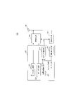
- FIG. 7 is a block diagram showing an example of the configuration of the base station 200 according to the first embodiment.
- the base station 200 includes an antenna 201, a wireless reception unit 202, a data reception processing unit 203, a PRACH detection unit 204, a timing control information generation unit 205, a data generation unit 206, a data transmission processing unit 207, and wireless communication.
- a transmission unit 208 is provided.
- the data reception processing unit 203, the PRACH detection unit 204, the timing control information generation unit 205, the data generation unit 206, and the data transmission processing unit 207 may be included in the control unit 209.
- the wireless reception unit 202 performs reception processing such as down-conversion and A / D conversion on the data signal and PRACH signal from the terminal 100 received via the antenna 201, and receives the received signal. Output to the processing unit 203 and the PRACH detection unit 204.
- the data reception processing unit 203 performs demodulation / decoding processing on received data signals other than PRACH. Further, the data reception processing unit 203 may perform channel estimation and timing estimation based on the received data signal. The data reception processing unit 203 outputs information regarding the estimated timing to the timing control information generation unit 205.
- the PRACH detection unit 204 performs correlation processing on the received PRACH Preamble signal with the series number corresponding to the set Preamble number and the replica signal of the Preamble signal generated by using the cyclic shift amount. Preamble signal is detected, and transmission timing and reception timing are estimated.
- the correlation processing in the PRACH detection unit 204 may be performed in the time domain to calculate the delay profile, or by performing the correlation processing (division processing) in the frequency domain and then performing the IFFT (Inversed Fourier Transform). It may be a process of calculating a delay profile.
- the calculated delay profile may be used to estimate transmission timing and / or reception timing.
- the PRACH detection unit 204 outputs, for example, information regarding the estimated transmission timing and / or reception timing to the timing control information generation unit 205.
- the PRACH detection unit 204 calculates the difference between the reference timing of the base station 200 and the arrival timing of the received signal, and outputs the calculation result to the timing control information generation unit 205.
- the timing control information generation unit 205 generates a TA command for the terminal 100 based on the information (for example, the timing estimation result) output from the PRACH detection unit 204 and the data reception processing unit 203. There may be multiple types of TA commands. Further, the timing control information generation unit 205 generates a timing adjustment value common to the cells. The cell-common timing adjustment value is generated based on, for example, at least one of the cell size formed by the satellite beam, the feeder link length, and the feeder link delay amount.
- the data generation unit 206 generates downlink data signals such as user data, synchronization signals, system information (notification information), individual control information (for example, RRC control information), and MAC control information for the terminal 100.
- the data generation unit 206 outputs the generated downlink data signal to the data transmission processing unit 207.
- the data transmission processing unit 207 encodes and modulates the downlink data signal output from the data generation unit 206 and the information output from the timing control information generation unit 205, and outputs the modulated signal to the wireless transmission unit 208.
- the wireless transmission unit 208 performs transmission processing such as D / A conversion, up-conversion, and amplification on the signal output from the data transmission processing unit 207, and transmits the wireless signal obtained by the transmission processing from the antenna 201. Send.
- the terminal 100 adjusts the timing by one or a plurality of timing adjustment values.
- two timing adjustments are performed: relatively fine-grained timing adjustment and relatively coarse-grained timing adjustment.
- the terminal 100 adjusts the transmission timing in sample units. For example, the transmission timing is adjusted so that the base station 200 receives the PUSCH OFDM symbol or the PRACH symbol within the CP length. In the relatively coarse-grained timing adjustment, the terminal 100 adjusts the transmission timing in units of slots and / or OFDM symbols. For example, in the base station 200, the transmission timing is adjusted so that it is received in the slot or OFDM symbol assumed by the base station 200.
- timing adjustment value for finely adjusting the particle size examples include the following values. -Timing adjustment value based on location information calculated by the terminal-Timing adjustment value by head path tracking calculated by the terminal-Timing adjustment value based on TA command 1 transmitted from the base station (Fine TA command)
- timing adjustment value for coarsely adjusting the particle size for example, the following values can be mentioned.
- -Cell-specific timing adjustment value notified from the base station cell-specific TA offset
- K adj, UE base station
- Timing adjustment value based on TA command 2 transmitted from the base station Coarse TA command
- timing adjustment value by the head path tracking calculated by the terminal will be described in the second embodiment.
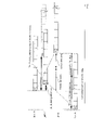
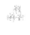
- FIG. 8 is a diagram showing an example of a sequence chart relating to timing control in the first embodiment.
- FIG. 8 shows an example of a signal (or a channel used for transmitting / receiving a signal) transmitted / received between the terminal 100 (UE) and the base station 200 (gNB) and a timing adjustment value used by the UE for signal transmission. Is done.
- a signal or a channel used for transmitting / receiving a signal
- gNB base station 200
- the base station transmits SSB and SIB (System Information Block).
- SSB and SIB may be transmitted periodically.
- the SSB contains signals for synchronization and cell-specific basic control information (eg, Master Information Block).
- the SIB contains cell-specific information for the terminal to access the base station.
- the SIB may include information indicating the position of the satellite (for example, satellite ephemeris).
- the SIB includes a Cell specific TA offset and a slot offset (K offset, cell ) indicating the slot position of data allocation.
- the terminal receives the SSB and SIB and sends a PRACH for initial access.
- the terminal adjusts the transmission timing of PRACH.
- the terminal adjusts the timing by using the value of the cell-specific TA offset notified from the base station and the timing adjustment value based on the position information calculated by the terminal.
- the timing adjustment value based on the position information may be described as "TA based on GNSS / ephemeris" or "GNSS / ephemeris based TA".
- the terminal acquires the position information of the terminal using the GNSS function or the like.
- the terminal calculates the distance between the satellite and the terminal from the position information of the satellite held or notified and the position information of the terminal.
- the terminal calculates the one-way propagation delay time by dividing the calculated distance by the radio wave propagation velocity (for example, 3 ⁇ 108 [m / s]). Twice the calculated propagation delay time corresponds to the round-trip propagation delay time (RTT).
- the calculated round-trip propagation delay time is a timing adjustment value based on the position information.
- the timing adjustment value based on the position information may be a value obtained by adding the processing delay time of the terminal and / or the base station to the calculated round-trip propagation delay time.
- the TA value is the value obtained by adding the cell-specific TA offset value notified from the base station to the timing adjustment value based on the position information.
- the terminal uses equations (1), (2) and (3) to determine the value TA final used for timing adjustment.
- the TA final determined by the equation (1), the TA NTN_offset determined by the equation (2), and the TA coarse determined by the equation (3) may be, for example, in ns (nano second) units.
- the first term on the right side of the above equation (1) is the same as the Rel.15 NR specification.
- Tc 0.509ns
- NTA is a correction value by the TA command transmitted from the base station.
- N TA offset is an offset value used for timing adjustment between different base stations.
- TA final which is the TA value calculated by equation (1), is synonymous with T TA described in section 4.3.1 of TS38.211V15.8.0, and is the same equation (1) as the Rel.15 NR specification.
- the correction term TA NTN_offset for NTN expressed by Eq. (2) is added to the first term. Since the Rel.15 NR specification can be reused, expansion to NTN can be realized with a small amount of change.
- TA location represents the round-trip propagation delay time calculated based on the location information.
- TA location may be represented by ns.
- the term of 106/2 ⁇ in the equation (3) represents the slot length in the case of the parameter ⁇ representing the subcarrier spacing, and the unit may be represented by ns, for example.
- M offset and cell are cell-specific TA offsets.
- the cell-specific TA offset indicates, for example, the number of slots to shift.
- M coarse is an offset described later and is set to zero at the time of PRACH transmission. Note that these offsets may indicate the offset time (for example, in ms unit) instead of the number of slots. In the case of an offset indicating time, the offset may not be multiplied by the term of 10 6/2 ⁇ indicating the slot length, or another coefficient may be multiplied or divided.
- the terminal transmits an uplink signal at a timing earlier than the reference reception timing of the downlink such as SSB by the above TA value (TA final ).
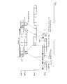
- FIG. 9 is a diagram showing an example of timing adjustment using a cell-specific TA offset value and a timing adjustment value based on position information.
- FIG. 9 illustrates the DL transmission slot and UL reception slot of the base station (gNB), and the DL reception slot and UL transmission slot of the terminal (UE).
- the horizontal axis of FIG. 9 indicates a time axis.
- FIG. 9 shows an example of an uplink signal transmitted at a transmission timing earlier than the reference reception timing of the downlink by the amount of the TA value.
- the TA value in FIG. 9 is represented by the sum of the cell-specific offset value and the timing adjustment value based on the position information.
- DL-UL timing difference due to feeder link delay shows the DL-UL timing difference caused by the feeder link delay that occurs when the cell-specific offset value is not used.
- the base station can shorten the DL-UL timing difference caused by, for example, the feeder link delay.
- the DL-UL timing difference can be controlled to the extent manageable by the base station (for example, within 10 ms).
- the propagation delay of the feeder link changes according to the position of the non-geostationary satellite that changes with time. Therefore, the delay amount with the shortest feeder link delay time may be corrected.
- the increase in notification overhead can be suppressed by notifying the terminal of coarse particle size values such as slot units and OFDM symbol units. It can handle long delay environments of satellite communication such as NTN environment.
- the base station receives the PRACH and detects the difference between the base station reference timing and the PRACH reception timing.
- the base station determines the TA command 1 (Fine TA command in FIG. 8) for correcting the timing corresponding to the detected difference, and transmits the PDSCH including the determined TA command 1.
- the TA command 1 may be, for example, a TA command similar to Rel.15 NR.
- the response to the terminal including the TA command 1 in S103 may be referred to as a RACH response (RAR).
- the CP length of PRACH is set to a value longer than the CP length of PUSCH. Therefore, even if the PRACH is received within the CP length of the PRACH, the reception timing at the PUSCH base station transmitted by the terminal after the PRACH may deviate from the CP length. In this step, the base station transmits TA command 1 and controls the transmission timing of the terminal so as to be within the CP length of PUSCH.
- the terminal sends PUSCH at the time / frequency resource specified by RAR.
- the time resource is a slot corresponding to the slot number offset by the amount of K offset, cell notified by the base station by SIB, and the terminal transmits at the timing of being received in the slot of this slot number in the base station.
- the terminal further adjusts the timing from the PRACH transmission timing according to the notified TA command 1. For example, in equation (1), timing adjustment is performed using TA final determined by using the value of TA command 1 for NTA, and PUSCH is transmitted.
- the terminal may notify the base station of the timing information (TA value report in FIG. 8). For example, the terminal may notify the TA final determined by using the equation (1), or may notify the TA NTN_offset or TA location which is an unknown value in the base station. In either case, the notification is rounded to a coarse particle size value such as slot length unit or OFDM symbol length unit. For example, conversion to a coarse-grained value may use a round or floor operation. Since this notification is used to control the PUSCH and / or HARQ-ACK allocation slots in the base station, it may be a coarse-grained notification such as in slot units. Coarse-grained notifications can reduce the notification overhead.
- the terminal may notify the location information acquired by GNSS as a substitute for the TA location , or may notify both the TA location and the location information.
- the position information to be notified may be, for example, position information having a particle size of about 1 km or position information limiting the values after the decimal point of latitude and longitude so that the calculation error of the propagation delay is equal to or less than a predetermined value. .. Further, as the position information, information for use for bandover control or the like may be reused.
- the base station transmits information for resolving conflicts in random access and / or RRC configuration information using PDSCH.
- the base station transmits a MAC CE including TA command 2 (Coarse TA command in FIG. 8).
- the TA command 2 is, for example, a slot-based particle size timing adjustment command.
- the base station sets the TA command 2 based on the information of the TA value notified from the terminal in S104.
- the base station may set the TA command 2 notified to the terminal to a smaller value.
- the PUSCH and / or HARQ-ACK slots assigned by DCI become slots with later timing, that is, slots with a larger slot number.
- the terminal can transmit PUSCH or HARQ-ACK after sufficient transmission preparation time after receiving DCI or PDSCH.
- the PUSCH and / or HARQ-ACK slots are earlier timing slots, i.e., slots with smaller slot numbers.
- the terminal can send the PUSCH or HARQ-ACK after sufficient transmission preparation time after receiving the DCI or PDSCH, even if the timing is adjusted to the previous timing by TA command 2.
- K offset cell is set according to the propagation delay that occurs in the terminal located farthest from the satellite in the cell
- TA command 2 notifying the terminal located farthest from the satellite will be zero. May be set.
- the terminal located closer to the satellite may be notified of the TA command 2 having a larger value. With such control, the closer the terminal is to the satellite, the lower the delay of transmission becomes possible.
- the base station may estimate the TA value of the terminal based on the notified position information and set the TA command 2 in the same manner as above.
- TA command 2 may be included in the RRC configuration information and sent.
- the terminal determines the TA value (TA final of equation (1)) by setting M coarse of equation (2) to the value notified by TA command 2 in the timing adjustment for subsequent PUSCH and HARQ-ACK transmissions. ) Is used.
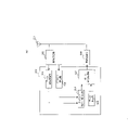
- FIG. 10 is a diagram showing an example of timing adjustment using each TA including the TA command 2.
- FIG. 10 illustrates the DL transmission slot and UL reception slot of the base station (gNB), and the DL reception slot and UL transmission slot of the terminal (UE).
- the horizontal axis of FIG. 10 indicates a time axis.
- “Coarse TA” in FIG. 10 indicates the TA notified by the TA command 2.
- “Fine TA” in FIG. 10 indicates the TA notified by the TA command 1.
- the “TA based on GNSS / ephemeris” and “Cell specific TA offset” in FIG. 10 may be the same as the “TA based on GNSS / ephemeris” and “Cell specific TA offset” shown in FIG. 9, respectively.
- Cell specific timing in FIG. 10 is the timing of PUSCH reception of the base station assumed in the case of transmission without using TA command 2 such as transmission of msg3 described above.
- the timing is set so that even the farthest terminal can transmit, considering the round-trip propagation delay time of the terminal farthest from the satellite.
- the timing is adjusted to the farthest terminal, a useless delay will occur for the terminal close to the satellite.
- the transmission / reception timing of the PUSCH can be made earlier than the Cell specific timing.
- the M coarse in the equation (2) may be converted by the particle size of the TA command 2.
- the particle size is in OFDM symbol units
- the value notified by TA command 2 (slot unit value) is converted to the OFDM symbol unit value by dividing by 14, which is the number of OFDM symbols per slot. May be good.
- the terminal When the satellite and / or the terminal moves beyond the threshold of the moving distance, the terminal again calculates the propagation delay from the GNSS position information and the position information from the satellite ephemeris, updates the TA location in the equation (1), and performs uplink transmission. ..
- the update of the TA location is not limited to the case where the satellite and / or the terminal moves by the threshold value or more, and may be executed, for example, at a predetermined cycle. Alternatively, it may be executed both when the satellite and / or the terminal moves beyond the threshold value and at a predetermined period.
- the frequency and cycle of updating the TA location , or the threshold value of the travel distance may be notified from the base station. Instead of the threshold value of the movement distance, the amount of change in the TA value due to the movement may be notified. Further, a predetermined value may be used for the frequency and cycle of updating the TA location or the threshold value of the moving distance.
- the terminal bases the corrected timing value information and / or the position information as in S104. You may notify the station.
- the terminal may transmit the user data without notifying the corrected timing value information and / or the position information.
- the base station may change the propagation delay amount due to the movement of the satellite, but for the stationary terminal or the terminal whose movement amount is equal to or less than the threshold value, the previous time. The amount of change in TA can be grasped based on the notified terminal position information. Therefore, it is possible to avoid frequently notifying the position information of the terminal, and it is possible to reduce the overhead of notifying the position information.
- the base station sends TA command 2 to change the PUSCH and / or HARQ-ACK allocation slot of the terminal. do.
- the terminal performs two timing adjustments, a relatively fine-grained timing adjustment and a relatively coarse-grained timing adjustment.
- the terminal makes different timing adjustments depending on the channel and / or the signal to be transmitted.
- the information notified from the base station to the terminal in the above sequence diagram is an example, and the present disclosure is not limited to this.
- the information notified by the TA command 2 of S105 and S109 may be notified by an offset value (K adj, UE ) for the allocated slot instead of the TA command.
- the offset value (K adj, UE ) is, for example, a timing adjustment value for each terminal.
- M coarse in equation (3) may be set to zero.
- the terminal interprets the PUSCH allocation slot as "n + K 2 + K offset, cell --K adj, UE ".
- n is the slot to which the DCI that allocates PUSCH is transmitted
- K 2 is the value notified by the DCI.
- K adj, UE the time required for preparing for PUSCH transmission and / or the time from the uplink slot that can be transmitted next after receiving DCI is set.
- the offset value (K adj, UE ) may be a negative value.
- FIG. 11 is a diagram showing an example of timing adjustment using information including K adj and UE .
- FIG. 11 illustrates the DL transmission slot and UL reception slot of the base station (gNB), and the DL reception slot and UL transmission slot of the terminal (UE).
- the horizontal axis of FIG. 11 indicates a time axis.
- the terminal determines the slot assigned to the PUSCH from the slot having the “Cell specific timing” to the slot shifted by the offset value of Kadj, UE .
- FIG. 11 shows an example in which the offset values of Kadj and UE are used in determining the allocation slot of PUSCH, but the present disclosure is not limited to this.
- the offset value of Kadj, UE may be applied in determining the transmission slot of HARQ-ACK transmission and / or SRS. If the offset value applies to HARQ-ACK transmission, n may be the PDSCH slot of interest for HARQ-ACK. Further, when the offset value is applied to the SRS transmission, n may be the DCI slot instructing the SRS transmission. Since the information indicating the offset from K offset and cell is notified instead of the TA command, the amount of information to be notified can be reduced.
- the particle size of the offset to be notified may be in units of slots or in units of OFDM symbols. Finer timing control is possible by using OFDM symbol units. Further, the offset value of Kadj, UE may not be applied depending on the channel and / or the signal, or different offset values may be used.
- the coarse-grained timing control is performed to suppress the increase in the notification overhead, and the long propagation delay and the propagation delay difference between the terminals. It is possible to control the transmission timing of the terminal, which is suitable for a large satellite communication environment.
- the configuration of the terminal according to the second embodiment may be the same as the configuration of the terminal 100 shown in the first embodiment. However, the processing in the timing adjustment unit 104 of the terminal 100 shown in the first embodiment is added.
- the timing adjustment unit 104 follows the reception timing of the SSB, PDCCH or PDSCH received by the wireless reception unit 107, and calculates the timing adjustment value according to the amount of change in the reception timing. When a plurality of paths (for example, delayed waves) are detected, the following reception timing may be the timing of the first path. Then, the timing adjustment unit 104 performs timing adjustment using any one or more of the calculated timing adjustment value by path tracking and the timing adjustment value shown in the first embodiment.
- the terminal uses equations (4) and (5) to determine the value TA final used for timing adjustment.
- the TA final determined by the equation (4) may be, for example, in ns (nano second) units.
- Equation (4) is the same as the equation (1), but the second term on the right side is expressed by the equation (5).
- TA path is added to the parameters on the right side of equation (2).
- TA path is a value of timing adjustment by path tracking.
- the terminal uses a case where the timing is adjusted based on the position information and a case where the timing is adjusted by path tracking in addition to the timing adjustment based on the position information according to the uplink transmission channel and / or the transmission timing of the terminal. good.
- the TA path may be set to zero. Which of the two cases to use may be instructed to the terminal by the control information from the base station.
- the rules may be defined in advance, and the terminal may be used properly according to the prescribed rules.
- the case where the timing adjustment is performed based on the position information is, for example, the following case.
- PRACH transmission ⁇ SRS transmission ⁇ First transmission after waking up from the sleep section of DRX (long sleep and / or short sleep) ⁇ First transmission after the TA valid timer expires ⁇ Transmission in IDLE or INACTIVE state
- timing adjustment based on position information and timing adjustment by path tracking are, for example, the following cases.
- RRC_CONNECTED state Transmission after the second time after waking up from sleep
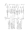
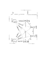
- FIG. 12 is a diagram showing an example of a sequence chart relating to timing control in the second embodiment.
- the signal (or the channel used for transmitting / receiving the signal) transmitted / received between the terminal 100 (UE) and the base station 200 (gNB) and the timing used by the UE for signal transmission are shown.
- An example of the adjustment value is shown.
- the same code number may be assigned and the description may be omitted.
- the base station transmits SSB and SIB.
- SSB and SIB may be transmitted periodically.
- the SSB contains signals for synchronization and cell-specific basic control information.
- the SIB contains cell-specific information for the terminal to access the base station.
- the SIB may include information indicating the position of the satellite (for example, satellite ephemeris).
- the SIB contains a Cell specific TA offset.
- the terminal may update the timing when the amount of change in the reception timing of the path exceeds the threshold value.
- the interval at which the TA value is updated and / or the threshold value of the amount of change that determines whether or not the TA value is updated may be specified by the base station or may be predetermined.
- the terminal notifies the base station of timing information (for example, at least one of the TA value and the position information) (TA value report in FIG. 12).
- the terminal may notify the sum of the TA location and the TA path .
- the notification may be rounded to a coarse particle size value such as a slot length unit or an OFDM symbol length unit.
- the terminal sleeps when there is no data to communicate with.
- the same operation as Rel.15 NR described in TS38.821 may be performed.
- the sleep of the terminal is not limited to the sleep of communication when there is no data to be communicated, and may be read as, for example, the sleep of CPU operation.
- the terminal acquires the position information of the terminal in the first transmission (for example, PUSCH transmission) after waking up from sleep.
- the terminal uses the changed position information of the satellite.
- the terminal updates the TA location , adjusts the timing, and performs PUSCH transmission.
- the terminal sets (reset or clears) the TA path to zero.
- the terminal may notify the base station of timing information (for example, TA value). Whether or not to notify the timing information to the base station may be specified by the base station (notified by SIB) depending on the type of satellite (geostationary satellite, non-geostationary satellite), etc., and the movement speed of the terminal and / or It may be set for each terminal depending on the type or the like, or may be notified for each terminal.
- timing information for example, TA value
- the terminal performs two timing adjustments, that is, the timing adjustment having a relatively fine particle size and the timing adjustment having a relatively coarse particle size.
- the terminal makes different timing adjustments depending on the channel and / or the signal to be transmitted.
- the terminal determines the TA path by path tracking, and adjusts the timing using the timing adjustment value including the TA path .
- the present disclosure is not limited to this.
- the same applies to the return from IDLE or INACTIVE, or the return from the expiration of the TA timer.
- the TA timer may be the timeAlignmentTimer described in TS38.321V15.8.0.
- K offset, cell , Kadj, UE , and TA command 2 may be used, may not be used, or a predetermined value may be used, as in the first embodiment. It may be used.
- the base station may explicitly notify the invalidation or may notify a predetermined value.
- the coarse-grained timing control is performed to suppress the increase in the notification overhead, and the long propagation delay and the propagation delay difference between the terminals. It is possible to control the transmission timing of the terminal, which is suitable for a large satellite communication environment. Further, in the second embodiment, the transmission timing control of an appropriate terminal can be performed by using the timing adjustment value by path tracking in the timing control.
- timing adjustment based on the position information of terminals and satellites for example, GNSS / ephemeris position information
- an environment outside the line of sight for example, an environment where there is no direct wave and reflected or diffracted waves arrive
- the actual propagation path is There will be an error.
- This error can be corrected by the TA command sent from the base station, but if the timing adjustment by the GNSS / ephemeris position information is repeated every time the position of the terminal or satellite changes, the error will occur again and the correction by the TA command will be performed again. Start over.
- the accuracy of timing control can be maintained and frequent TA command transmission from the base station can be avoided by performing correction by path tracking without re-adjusting the timing by GNSS / ephemeris position information frequently.
- the timing accuracy can be improved and the overhead can be reduced.
- the timing adjustment by GNSS / ephemeris position information is performed. By doing so, a certain degree of timing accuracy can be maintained.
- the configuration of the terminal and the base station according to the present embodiment may be the same as the configuration of the terminal 100 and the base station 200 shown in the first embodiment. However, the operations related to the timing adjustment of the terminal 100 and the base station 200 shown in the first embodiment are different.
- timing adjustment is performed by "Koffset" that defines the transmission slot timing.
- the control unit 109 has a first offset (eg, K offset, cell ) and a first, based on information about a control signal (eg, DCI or PDCCH) for scheduling.
- the uplink transmission timing (eg, transmission slot timing) is controlled by using any one of the second offsets (for example, K offset, UE ) shorter than the offset.
- the wireless transmission unit 105 performs uplink transmission based on control of uplink transmission timing.
- the control unit 209 has a first offset (for example, K offset, cell) and a first offset (for example, K offset, cell ) based on the information regarding the control signal for scheduling (for example, DCI or PDCCH).
- the uplink reception timing (eg, reception slot timing) is controlled by using any one of the second offset (for example, K offset, UE ) shorter than the first offset.
- the wireless reception unit 202 performs uplink reception based on control of uplink reception timing.
- Koffset for example, "K offset, cell " which is a cell-specific value or "K offset, UE " which is a terminal-specific (UE-specific) value may be set.
- the terminal-specific K offset, UE is shorter than the cell-specific K offset, cell .
- the cell-specific K offset, cell may be notified to the terminal 100 by the SIB.
- the terminal 100 is, for example, a transmission (for example, a PUSCH for MSG3 at the time of initial access or an ACK / NACK for a PDSCH for MSG4 (for example, also referred to as HARQ-feedback)) until the K offset and UE of each terminal are notified.
- the terminal-specific K offset, UE may be notified to the terminal 100 by at least one of the terminal-specific RRC message, MAC CE, and DCI. Further, as information on the K offset and UE of each terminal, the relative value (or difference) from the K offset and cell and the relative value (or difference) from the previously notified K offset and UE value are notified to the terminal 100. May be done.
- the K offset and UE of each terminal may be updated as appropriate with the movement of at least one of the satellite and the terminal.
- the K offset, UE of each terminal may be updated as the terminal 100 moves.
- the update frequency of K offset and UE for each terminal is relatively low, notification by RRC message is appropriate.
- the K offset, UE of each terminal may be updated with the high-speed movement of the satellite.
- the relative value (for example, for example) of the K offset and UE of each terminal by MAC CE or DCI that can be notified and reflected in a shorter time than the RRC message. The difference) may be notified to the terminal 100.
- the amount of notification information can be reduced and the K offset can be notified more quickly.
- a DCI common to the group for example, DCI format 2_0, etc. may be used in addition to the DCI for each terminal.
- the recognition of the K offset and UE values does not match between the base station 200 and the terminal 100 due to an error in receiving the notification information or an error in the ACK / NACK signal for the notification information.
- a relative value or difference
- the difference from the previous value that may be misrecognized between the base station 200 and the terminal 100 is sent to the terminal 100. Since it is notified, it is difficult to reconcile the recognition between the base station 200 and the terminal 100.
- the terminal 100 and the base station 200 are set to cell-specific K offset, cell and terminal-specific K offset, UE based on, for example, information regarding DCI (or PDCCH) for scheduling. Use either one to control the transmission / reception timing of the uplink signal. For example, when the terminal 100 and the base station 200 are scheduled by a specific method or a specific DCI, the terminal-specific K offset, UE is notified to the terminal 100, even if the terminal-specific K offset , UE is notified to the terminal 100. Instead, use cell-specific K offset, cell .
- FIG. 13 is a diagram showing an example of a flowchart relating to control of transmission slot timing of an uplink signal (for example, PUSCH or PUCCH) in the terminal 100 according to the present embodiment.
- an uplink signal for example, PUSCH or PUCCH
- FIG. 13 each process from step 301 (S301) to S305 in FIG. 13 will be described.
- the terminal 100 receives, for example, a cell-specific K offset, cell .
- the cell-specific K offset, cell may be included in the SIB, for example.
- the terminal 100 determines, for example, whether or not a terminal-specific K offset, UE has been received. For example, the K offset and UE of each terminal may be notified from the base station 200 to the terminal 100 at the timing of receiving PDSCH (msg4) (processing of S105) or receiving PDSCH (S109) shown in FIG. Further, for example, when transmission / reception at the time of initial access or when the cell size is small (when the cell size is less than the threshold value), K offset, UE for each terminal is not set (in other words, notification) from the base station 200. In some cases, the data is scheduled (for example, when receiving a DCI for uplink or downlink data allocation).
- ⁇ S303> When a terminal-specific K offset, UE is received (S302: Yes), the terminal 100 determines, for example, whether the PUSCH or PUCCH transmission was scheduled by a particular method or a particular DCI. Specific methods and examples of specific DCI will be described later.
- the terminal 100 may be, for example, a cell. Determine the transmit slot based on the unique K offset, cell .
- the terminal 100 may be, for example, a terminal. Determine the transmit slot based on the individual K offset, UE .
- the terminal 100 even if the terminal 100 receives the terminal-specific K offset, UE , if it is scheduled by a specific method or a specific DCI, the terminal 100 is based on the cell-specific K offset, cell . Determine the transmission slot.
- the offset Koffset used to determine the transmission slot is determined based on the DCI format.
- the terminal 100 uses a cell-specific K offset, cell when the DCI format for scheduling is DCI format 0_0 or DCI format 1_0.
- the particular DCI is, for example, DCI format 0_0 and DCI format 1_0.
- DCI formats such as DCI format 0_0 and DCI format 1_0 are limited to DCI formats that do not support MIMO (Multiple-Input Multiple-Output), notifications of consecutive resource blocks, and so on. May be a limited DCI format, a DCI format used for scheduling PDSCHs common to cells, or a DCI format with a small number of bits (eg, the number of bits is less than the threshold). Such DCI can be used, for example, for transmission with a smaller number of bits or transmission with lower overhead.
- MIMO Multiple-Input Multiple-Output
- DCI formats such as DCI format 0_1, DCI format 0_2, DCI format 1_1 or DCI format 1_2, which are different from the specific DCI mentioned above, are more flexible and can notify scheduling information with less restrictions, for example. It may be a DCI format for high-speed data communication or high-reliability low-latency data communication.
- the terminal 100 determines the transmission slot based on the cell-specific K offset, cell .
- the terminal 100 determines the transmission slot based on the K offset, UE of each terminal.
- terminal 100 determines the PUSCH transmit slot scheduled by DCI format 0_0 by slot n + K 2 + K offset, cell and transmits PUSCH scheduled by DCI format 0_1 or DCI format 0_2.
- the slot may be determined by slot n + K 2 + K offset, UE .
- slot n is the slot number to which DCI was notified.
- the terminal 100 determines the transmission slot of HARQ-feedback (or ACK / NACK) for PDSCH scheduled by DCI format 1_0 by slot n'+ K 1 + K offset, cell .
- the HARQ-feedback (or ACK / NACK) transmit slot for PDSCH scheduled by DCI format 1_1 or DCI format 1_2 may be determined by slot n'+ K 1 + K offset, UE .
- slot n' is the slot number to which PDSCH was transmitted.
- the terminal 100 Due to the determination of the transmission slot, for example, even if the recognition deviation of the K offset, UE value of each terminal occurs between the base station 200 and the terminal 100, the terminal 100 is based on the cell-specific K offset, cell . Communication can be continued.
- the base station 200 when the base station 200 does not detect PUSCH or HARQ-feedback (for example, PUCCH) from the terminal 100 for a certain period of time, it is determined that a recognition discrepancy has occurred between the base station 200 and the terminal 100. It may communicate with the terminal 100 based on DCI format 0_0 or DCI format 1_0 (in other words, cell-specific K offset, cell ).
- DCI format 0_0 or DCI format 1_0 in other words, cell-specific K offset, cell
- the base station 200 notifies the terminal 100 of the K offset and UE values of each terminal again by communication using DCI format 0_0 or DCI format 1_0, so that the base station 200 and the base station 200 have the K offset and UE values.
- the recognition with the terminal 100 may be matched.
- the terminal 100 and the base station 200 may reset the cumulative value of the difference information previously notified by MAC CE or DCI in the past.
- the recognition between the base station 200 and the terminal 100 can be matched with respect to the values of K offset and UE .
- cell-specific K offset, cell -based communication using DCI format 0_0 or 1_0 is sufficient for the notification of K offset, UE for matching the recognition between the terminal 100 and the base station 200.
- the terminal 100 uses, for example, DCI format 0_1, 0_2, 1_1, 1_2, which enables more flexible scheduling, and is used for individual terminals with a smaller delay. It is possible to transmit using K offset and UE of.
- the offset Koffset used for determining the transmission slot is determined based on the type of search space (SS: Search Space) used for scheduling (for example, transmission of DCI).
- SS Search Space
- the terminal 100 uses a cell-specific K offset, cell when the search space used for transmitting DCI for scheduling is a search space common to a plurality of terminals (common search space).
- the particular method is, for example, a method in which a DCI (or PDCCH) containing scheduling information is transmitted in a common search space.
- the terminal 100 determines the transmission slot based on the cell-specific K offset, cell .
- the terminal 100 determines the transmission slot based on the terminal individual K offset, UE . ..
- the terminal 100 determines the transmission slot of the PUSCH scheduled by the DCI transmitted in the common search space by slot n + K 2 + K offset, cell , and the DCI transmitted in the terminal individual search space.
- the PUSCH transmit slot scheduled by may be determined by slot n + K 2 + K offset, UE .
- slot n is the slot number to which DCI was notified.
- the terminal 100 sets the transmission slot of HARQ-feedback (or ACK / NACK) for PDSCH scheduled by DCI transmitted in the common search space to slot n'+ K 1 + K offset,
- the HARQ-feedback (or ACK / NACK) transmission slot for the DCI-scheduled PDSCH determined by the cell and transmitted in the terminal-specific search space is determined by slot n'+ K 1 + K offset, UE . good.
- slot n' is the slot number to which PDSCH was transmitted.
- the terminal 100 Due to the determination of the transmission slot, for example, even if the recognition deviation of the K offset, UE value of each terminal occurs between the base station 200 and the terminal 100, the terminal 100 is based on the cell-specific K offset, cell . Communication can be continued.
- the DCI for scheduling to the terminal 100 has, for example, a larger number of candidates for the number of CCEs (Control Channel Elements) or a larger number of blind decodings (for example, more resource candidates for mapping the DCI) in normal communication.
- the terminal 100 may be notified in the terminal individual search space.
- the DCI for scheduling is a candidate for the number of CCEs or a candidate for the resource that maps the DCI.
- the base station 200 may not detect PUSCH or HARQ-feedback (for example, PUCCH) from the terminal 100 for a certain period of time, it is determined that a recognition discrepancy has occurred between the base station 200 and the terminal 100, and a common search is performed. It may communicate with the terminal 100 by transmitting DCI using a space (in other words, a cell-specific K offset, cell ). For example, the base station 200 notifies the terminal 100 of the K offset and UE values of each terminal again by communication using the common search space, and recognizes the K offset and UE values between the base station 200 and the terminal 100. You may match.
- a space in other words, a cell-specific K offset, cell
- the offset Koffset used to determine the transmit slot is determined based on the control channel transmit resource (eg, CORESET: Control Resource Set) used for scheduling (eg, DCI transmission).
- the terminal 100 uses a cell-specific K offset, cell when the CORESET used for transmitting the DCI for scheduling is a specific CORESET.
- the particular method is, for example, a method in which a DCI (or PDCCH) containing scheduling information is transmitted at a particular CORESET.
- the specific CORESET may be CORESET0.
- the resource of CORESET0 may be notified by the SIB and may be a resource common to a plurality of terminals in the cell.
- CORESET which is different from CORESET0, may be a resource set individually for each terminal.
- the specific CORESET number is not limited to 0. Also, the number of specific CORESETs is not limited to one.
- the terminal 100 determines the transmission slot based on the cell-specific K offset, cell .
- the terminal 100 determines the transmission slot based on the K offset, UE of each terminal.
- terminal 100 determines a PUSCH transmit slot scheduled by DCI transmitted at CORESET0 by slot n + K 2 + K offset, cell and is scheduled by DCI transmitted at CORESET different from CORESET0.
- the transmission slot of the PUSCH that has been created may be determined by slot n + K 2 + K offset, UE .
- slot n is the slot number to which DCI was notified.
- the terminal 100 sets the transmission slot of HARQ-feedback (or ACK / NACK) for PDSCH scheduled by DCI transmitted in CORESET0 by slot n'+ K 1 + K offset, cell .
- the HARQ-feedback (or ACK / NACK) transmit slot for the DCI-scheduled PDSCH transmitted in CORESET different from CORESET0 may be determined by slot n'+ K 1 + K offset, UE .
- slot n' is the slot number to which PDSCH was transmitted.
- the terminal 100 Due to the determination of the transmission slot, for example, even if the recognition deviation of the K offset, UE value of each terminal occurs between the base station 200 and the terminal 100, the terminal 100 is based on the cell-specific K offset, cell . Communication can be continued.
- the DCI for scheduling to the terminal 100 may be notified to the terminal 100 in a normal time, for example, in a terminal-specific CORESET (here, a CORESET different from CORESET0) in which resources can be set more flexibly.
- the recognition deviation of the K offset and UE values of each terminal occurs, the DCI for scheduling is notified to the terminal 100 at CORESET0 (for example, CORESET common to a plurality of terminals).
- CORESET0 for example, CORESET common to a plurality of terminals
- the base station 200 may communicate with the terminal 100 by transmitting DCI using a cell-specific K offset (cell ).
- the base station 200 notifies the terminal 100 of the K offset and UE values of each terminal again by communication using CORESET0, and the base station 200 and the terminal 100 recognize the K offset and UE values together. May be good.
- the offset Koffset used to determine the transmission slot is determined based on the scheduling method.
- the terminal 100 uses cell-specific K offset, cell when the scheduling method by DCI (or PDCCH) for scheduling is SPS (Semi-persistent scheduling).
- the particular scheduling method is, for example, SPS.
- terminal 100 determines the HARQ-feedback (or ACK / NACK) transmission slot for PDSCH scheduled by SPS by slot n'+ K 1 + K offset, cell , and is scheduled by a method different from SPS.
- the HARQ-feedback (or ACK / NACK) transmission slot for the PDSCH may be determined by slot n'+ K 1 + K offset, UE .
- slot n' is the slot number to which PDSCH was transmitted.
- the terminal 100 Due to the determination of the transmission slot, for example, even if the recognition deviation of the K offset, UE value of each terminal occurs between the base station 200 and the terminal 100, the terminal 100 is based on the cell-specific K offset, cell . Communication can be continued.
- the overhead can increase as the terminal-specific K offset, UE is updated frequently as the LEO satellites move.
- the SPS can transmit with reduced PDCCH overhead for periodic traffic or small amounts of data transmission. Therefore, according to the method 4, for the HARQ-feedback for PDSCH scheduled by SPS, by using the cell-specific K offset and cell instead of the terminal-specific K offset and UE , the terminal-specific K offset and cell are used. , UE does not need to be updated frequently, and overhead can be reduced.
- the offset Koffset used to determine the transmit slot is determined based on the HARQ process (retransmission process) assigned to the PUSCH or PDSCH.
- the terminal 100 selects either a cell-specific K offset, cell or a terminal-specific K offset, UE according to the HARQ process number notified by the DCI for scheduling.
- a particular method is one in which PUSCH or PUCCH is assigned to a particular HARQ process and transmitted.
- a specific HARQ process be a HARQ process with HARQ process number 0.
- the specific HARQ process may be, for example, a HARQ process assigned in the SPS described in Method 3 (including, for example, HARQ process number 0).
- the HARQ process number may be notified to the terminal 100 by DCI, for example. For example, when the HARQ process number is 0, the terminal 100 selects a cell-specific K offset, cell .
- the terminal 100 determines the transmission slot based on the cell-specific K offset, cell .
- the terminal 100 determines the transmission slot based on the K offset, UE of each terminal.
- the terminal 100 determines the transmission slot of PUSCH to which HARQ process number 0 is assigned by slot n + K 2 + K offset, cell , and is assigned a HARQ process number different from HARQ process number 0.
- the transmission slot of PUSCH may be determined by slot n + K 2 + K offset, UE .
- slot n is the slot number to which DCI was notified.
- the terminal 100 determines the transmission slot of HARQ-feedback (or ACK / NACK) for the PDSCH to which HARQ process number 0 is assigned by slot n'+ K 1 + K offset, cell .
- the HARQ-feedback (or ACK / NACK) transmission slot for a PDSCH assigned a HARQ process number different from HARQ process number 0 may be determined by slot n'+ K 1 + K offset, UE .
- slot n' is the slot number to which PDSCH was transmitted.
- the terminal 100 Due to the determination of the transmission slot, for example, even if the recognition deviation of the K offset, UE value of each terminal occurs between the base station 200 and the terminal 100, the terminal 100 is based on the cell-specific K offset, cell . Communication can be continued. For example, the base station 200 may continue communication with the terminal 100 by scheduling using HARQ process number 0.
- the base station 200 notifies the terminal 100 of the K offset, UE value of each terminal again by communication using the HARQ process number 0 (in other words, the cell-specific K offset, cell ), and the base station 200.
- the recognition of 200 and the terminal 100 may be combined.
- the terminal 100 can be either a cell-specific K offset, a cell or a terminal-specific K offset, UE based on the combination of DCI format (method 1) and search space used to transmit DCI for scheduling. Either one may be used.
- the terminal 100 uses the cell-specific K offset, cell when scheduled by DCI format 0_0 or 1_0 using the common search space, and uses the terminal-specific K offset, UE in other cases. You may. The same applies to the other combinations of methods 1 to 5.
- the base station 200 may notify whether the cell-specific K offset, cell or the terminal-specific K offset, UE is used in the DCI for data scheduling.
- the terminal 100 has a cell-specific K offset, cell and a terminal-specific K based on information about the DCI for scheduling (eg, a specific DCI or a specific method).
- the uplink transmission timing is controlled by using either offset or UE .
- the K offset of each terminal, the K offset of the cell even when the UE is notified to the terminal 100, Communication between the terminal 100 and the base station 200 can be continued based on the transmission slot timing using the cell . Therefore, according to the present embodiment, appropriate timing control according to the propagation delay between the terminal 100 and the base station 200 can be realized.
- the uplink transmission timing is set using either the cell-specific K offset, cell or the terminal-specific K offset, UE .
- the same effect can be obtained by controlling it.
- DCI whose contents do not change depending on the settings of each terminal such as DCI format 0_0 and DCI format 1_0 are sometimes called Fallback DCI.
- the cell-specific K offset, cell may be used, and in other cases, the terminal-specific K offset, UE may be used.
- the configuration of the terminal and the base station according to the present embodiment may be the same as the configuration of the terminal 100 and the base station 200 shown in the first embodiment. However, the operations related to the timing adjustment of the terminal 100 and the base station 200 shown in the first embodiment are different. For example, the terminal 100 and the base station 200 may adjust the timing by the “Koffset” that defines the transmission slot timing, as in the third embodiment.
- HARQ-feedback for example, for data transmission, a HARQ process in which HARQ-feedback is enabled (enabled) or a HARQ process in which HARQ-feedback is disabled (disabled) is used.
- Information on enabling or disabling HARQ-feedback may be notified from the base station 200 to the terminal 100 as individual information to the HARQ process, for example.
- the terminal 100 transmits HARQ-feedback (eg, ACK / NACK) to, for example, the PDSCH (or transport block) of the HARQ process with HARQ-feedback enabled, and HARQ with HARQ-feedback disabled. Do not send HARQ-feedback to the process's PDSCH (or transport block).
- HARQ-feedback eg, ACK / NACK
- a HARQ process with HARQ-feedback enabled is assigned to the PDSCH used for notification of Koffset (for example, K offset, UE , K offset, adj , or Coarse TA).
- Koffset for example, K offset, UE , K offset, adj , or Coarse TA
- terminal 100 may receive information about Koffset by a HARQ-feedback enabled retransmission process. In other words, terminal 100 does not receive information about Koffset by the retransmission process with HARQ-feedback disabled.
- the terminal 100 may reflect, for example, the received Koffset value at a predetermined timing. For example, when the Koffset is notified by the MAC CE, the terminal 100 may reflect the Koffset 3 slots (or after the X slot) from the HARQ-ACK transmission timing to the PDSCH including the MAC CE. Further, for example, when the Koffset is notified by RRC signaling, the terminal 100 may reflect the Koffset 10 ms after the receiving slot of the PDSCH.
- the base station 200 can infer whether or not the terminal 100 has correctly received the MAC CE by receiving the HARQ-feedback signal transmitted from the terminal 100 in response to the Koffset notification. Therefore, it is possible to reduce the possibility that the recognition of the Koffset value does not match between the base station 200 and the terminal 100.
- the reflection timing of the Koffset after the Koffset is received in the terminal 100 is uniquely defined, when the Koffset is correctly received in the terminal 100, the recognition of the Koffset is recognized between the base station 200 and the terminal 100. Can be matched.
- the HARQ process in which HARQ-feedback is enabled and the HARQ- Any of the HARQ processes with feedback disabled may be assigned.
- terminal 100 may receive information about Koffset by either a HARQ-feedback enabled retransmission process or a HARQ-feedback disabled retransmission process.
- Base station 200 when using a HARQ process in which HARQ-feedback is disabled, causes an error in Koffset notification due to transmission of a low target error rate (BLER: Block Error Rate) such as use of low MCS or Repetition transmission. Therefore, the probability of occurrence of a recognition deviation of the transmission timing between the base station 200 and the terminal 100 may be reduced.
- BLER Block Error Rate
- the terminal 100 may reflect, for example, the received Koffset value at a predetermined timing. For example, when the Koffset is notified by the MAC CE, the terminal 100 may reflect the Koffset 3 slots (or after the X slot) from the HARQ-ACK transmission timing to the PDSCH including the MAC CE.
- HARQ-ACK transmission will not be performed.
- the terminal 100 is not actually transmitted, but is 3 slots later (or after the X slot) from the timing assumed for HARQ-ACK transmission (for example, called virtual HARQ-ACK timing). Koffset may be reflected.
- the transmission timing of HARQ-ACK is determined based on, for example, the value of K1 (offset value from the PDSCH slot) notified by DCI at the time of scheduling PDSCH. For example, if a HARQ process with HARQ-feedback disabled is used, terminal 100 does not actually send HARQ-ACK, but virtual HARQ-ACK timing based on the notified K1 value. May be determined.
- the K1 value is essentially unnecessary, so the K1 value may not be notified by DCI, used for other purposes, or treated as an invalid field. There is. In these cases, one of the configured values (eg, minimum or maximum) is used to determine the virtual HARQ-ACK timing. You may. Alternatively, the K1 value used when HARQ-feedback is disabled may be configured, or the default value for the K1 value may be specified in the specification.
- the notification method 2 uniquely defines the Koffset reflection timing regardless of whether HARQ-feedback is enabled or disabled, for example, the base station 200 and the terminal 100 when the Koffset value is correctly received by the terminal 100. Koffset recognition can be matched with.
- the K offset and UE of each terminal are K offset , for example, using the K adj and UE which are the adjustment values described in the first embodiment or the second embodiment.
- cell - may be calculated by K adj, UE .
- the K offset, UE for each terminal may be calculated by K offset, cell --TA coarse , for example, using a coarse TA value (for example, Coarse TA).
- the K adj, UE or coarse TA value may be notified to terminal 100, for example, by at least one of RRC messages, MAC CE or DCI.
- the terminal 100 when Koffset is notified by Group common DCI in which information for a plurality of terminals such as DCI format 2_x is included in one DCI, the terminal 100 has 3 slots (or X slots) from the slot receiving the DCI. ) You may reflect Koffset later. For example, in order to minimize the occurrence of recognition deviation of K offset and UE , the terminal 100 may transmit a HARA-ACK signal to the base station 200 when receiving DCI containing information on K offset and UE . good.
- the HARQ-feedback for the PDSCH scheduled by the DCI of RA-RNTI has a cell-specific K. offset
- cell may be used. That is, the RNTI of the DCI used for scheduling may determine whether to use the cell-specific K offset, cell or the terminal-specific K offset, UE .
- cell-specific K offset, cell may be used for HARQ-feedback for PDSCH scheduled by DCI of RNTI other than C-RNTI, which is a terminal-specific ID.
- the cell-specific K offset, cell is used for the PUSCH scheduled by the UL grant for Msg3 notified by the RACH response (MSG2). May be done.
- the cell-specific K offset, cell may be a satellite beam-specific Koffset value or an SSB beam-specific Koffset value specified in 3GPP.
- the cell-specific K offset and cell may be K offset values notified by SIB.
- the K offset and UE for each terminal may be the Koffset value notified by the RRC reconfiguration message notified for each terminal, or may be the Koffset value notified by MAC CE or DCI.
- an offset value for determining the transmission slot of PUSCH or PUCCH (HARQ-feedback) (for example, K offset, cell + K1, K offset, cell + K2, or K offset, UE + K1, K offset ).
- UE + K2 multiply the slot length for time conversion)
- the PUSCH or PUCCH transmission slot is from the DCI or PDSCH reception slot.
- the terminal 100 does not have to transmit PUSCH or PUCCH.
- the terminal 100 may start, for example, a radio link failure procedure (RLF (Radio Link Failure) procedure) or a beam failure procedure (Beam Failure or Beam Recovery). You may also send RACH for resynchronization.
- RLF Radio Link Failure
- Beam Failure or Beam Recovery You may also send RACH for resynchronization.
- HARQ-feedback may be referred to as HARQ-ACK or ACK / NACK.
- the NTN environment for example, satellite communication environment
- the present disclosure is not limited to this.
- the present disclosure may be applied to other communication environments (eg, LTE and / or NR terrestrial cellular environments).
- GNSS position detection using satellite signals
- position detection by a ground cellular base station, WiFi signals and / or Bluetooth registered trademark.
- Position detection using a signal, position detection using an acceleration sensor, or a combination thereof may be performed.
- altitude information may also be included in the position information. Further, it may be a value of a coordinate system defined separately. Altitude information may be obtained from a barometric pressure sensor or the like.
- the terminal has shown an example of notifying the base station of at least one of the TA value and the position information, but the timing of notification (notification trigger) may be different from that of the above-described embodiment. ..
- the notification trigger may be based on other indicators, such as the amount of change in channel quality, instead of the amount of change in TA value or position.
- RSRP Reference Signal Received Power
- RSRQ Reference Signal Received Quality
- SINR Signal to Interference plus Noise. Ratio
- the index to be used and the threshold value of the amount of change may be configured from the base station.
- the base station may instruct which information to notify, such as TA value and location information.
- the cell-specific TA offset, K offset, cell, etc. may notify the difference from the value notified by the cell parameter (for example, the value corresponding to RTT near the center of the cell). By notifying the difference, the amount of notification information can be reduced.
- the TA command 1 that controls with fine particle size may use the TA command of Rel15 NR without changing the particle size and range. By using it without changing the particle size and range, it is possible to reduce the amount of change in the implementation between the terminal and the base station. Further, the particle size and range of the TA command 2 may be notified from the base station by SIB or the like. As a result, the notification overhead of TA command 2 can be reduced with an appropriate number of bits (for example, the minimum number of bits) depending on the cell size, satellite altitude, and the like. The same applies to the particle size and range of K offset , K adj, and UE .
- the TA command 1 may be expressed as a relative value with the TA command 1 transmitted at the previous transmission timing or a control value with respect to the TA value transmitted at the previous transmission timing.
- the N TA in Eq. (1) uses the accumulated value of the TA command 1 received so far.
- the TA command 2 may be expressed by a relative value from the TA command 2 transmitted at the previous transmission timing or a control value with respect to the TA value transmitted at the previous transmission timing.
- M coarse in Eq. (2) uses the accumulated value of the TA command 2 received so far.
- the cell-specific TA offset and / or K offset, cell may be a value for each beam associated with the SSB.
- the amount of information to be notified may be reduced by notifying the difference from the value notified in cell units.
- the signal and / or information notified from the base station may be transmitted by SSB and / or SIB, or transmitted by a method that can be received by a plurality of terminals, for example, DCI format (DCI format 2_x, etc.) common to the group. You may. Also, if the same timing adjustment value is used for multiple terminals by notifying multiple terminals of TA command 1 and / or TA command 2 at once, TA command 1 and / or TA command 2 May be transmitted by DCI format (DCI format 2_x, etc.) common to the group.
- DCI format DCI format 2_x, etc.
- timing adjustment values having different particle sizes and ranges are used, but the same particle size and range may be used, or one of them may be different. Further, three or more kinds of timing adjustment values having different particle sizes and ranges may be used.
- the timing adjustment based on the GNSS / ephemeris position information of each of the above-described embodiments and the timing adjustment by path tracking are not performed by commands from the base station, but are autonomously performed by the terminal.
- the base station detects the reception timing for the received signal from the terminal, but if the reception timing changes significantly in the averaging window at the time of detection, the accuracy of the reception timing detection may deteriorate. Therefore, the timing adjustment that the terminal autonomously performs may specify the minimum interval and / or the minimum timing change width, and the terminal may be set to change within the specified range. Further, the information regarding the minimum interval and / or the minimum change width may be notified from the base station to the terminal.
- the terminal may perform timing adjustment based on GNSS / ephemeris position information and timing adjustment by path tracking, triggered by an instruction from the base station.
- the cell may be an area defined by the received power of SSB and / or CSI-RS transmitted by the base station (or satellite), or may be an area defined by a geographical location. .. Further, the cell of the above embodiment may be replaced with a beam defined by SSB.
- Satellite ephemeris information which is information on the position of satellites, may be notified by system information or the like, or may be held by a terminal (or base station) in advance. Further, the terminal (or base station) may update the Satellite ephemeris information when communication is possible. In addition, the terminal (or base station) may specify the position of the satellite by using other information.
- timing control may be performed according to the timing control information common to the cells notified from the base station.
- the base station may transmit timing control information corresponding to the propagation delay amount near the center of the cell.
- the terminal transmits PUSCH without using TA command 2. You may.
- cell-specific TA offset, TA command 1, TA command 2, and TA value notification from the terminal is not limited to those described above.
- this TA control may be performed for each TA group.
- some parameters such as cell-specific TA offset may be shared.
- Koffset may be set for each TA group.
- the Koffset set in PCell or SpCell may be used in another Component carrier or Cell (SCell). This can reduce the amount of notification information.
- timing adjustment value based on the position information is described as a fine-grained timing adjustment value, it may be positioned as a coarse-grained timing adjustment value in consideration of the accuracy of the position information and the like.
- the base station may be referred to as gNodeB or gNB. Further, the terminal may be referred to as a UE.
- Slots may be replaced with time slots, mini slots, frames, subframes, etc.
- the radio wave propagation velocity is described as about 3 ⁇ 10 8 [m / s], but the present invention is not limited to this, and for example, a numerical value such as 2.97992 ⁇ ⁇ 10 8 [m / s] is used. You may use it.
- the accuracy of the radio wave propagation velocity may depend on the implementation.
- the downlink control signal (or downlink control information) related to one embodiment of the present disclosure may be, for example, a signal (or information) transmitted on the Physical Downlink Control Channel (PDCCH) of the physical layer. It may be a signal (or information) transmitted by the upper layer Medium Access Control Control Element (MAC CE) or Radio Resource Control (RRC). Further, the signal (or information) is not limited to the case of being notified by the downlink control signal, and may be predetermined in the specifications (or standards) or may be preset in the base station and the terminal.
- PDCCH Physical Downlink Control Channel
- MAC CE Medium Access Control Element
- RRC Radio Resource Control
- the signal (or information) is not limited to the case of being notified by the downlink control signal, and may be predetermined in the specifications (or standards) or may be preset in the base station and the terminal.
- the uplink control signal (or uplink control information) related to one embodiment of the present disclosure may be, for example, a signal (or information) transmitted in the PUCCH of the physical layer, and the MAC CE or the MAC CE of the upper layer or It may be a signal (or information) transmitted in RRC. Further, the signal (or information) is not limited to the case of being notified by the uplink control signal, and may be predetermined in the specifications (or standards) or may be preset in the base station and the terminal. Further, the uplink control signal may be replaced with, for example, uplink control information (UCI), 1st stage sidelink control information (SCI), or 2nd stage SCI.
- UCI uplink control information
- SCI 1st stage sidelink control information
- 2nd stage SCI 2nd stage SCI.
- the base station is a Transmission Reception Point (TRP), a cluster head, an access point, a Remote Radio Head (RRH), an eNodeB (eNB), a gNodeB (gNB), a Base Station (BS), a Base Transceiver. It may be a Station (BTS), a master unit, a gateway, or the like. Further, in side link communication, a terminal may be used instead of the base station. Further, instead of the base station, it may be a relay device that relays the communication between the upper node and the terminal. It may also be a roadside device.
- TRP Transmission Reception Point
- RRH Remote Radio Head
- eNB eNodeB
- gNB gNodeB
- BS Base Station
- BTS Base Transceiver
- a terminal may be used instead of the base station.
- the base station it may be a relay device that relays the communication between the upper node and the terminal. It may also be a roadside device.
- an embodiment of the present disclosure may be applied to any of an uplink, a downlink, and a side link, for example.
- an embodiment of the present disclosure may be an uplink Physical Uplink Shared Channel (PUSCH), a Physical Uplink Control Channel (PUCCH), a Physical Random Access Channel (PRACH), a downlink Physical Downlink Shared Channel (PDSCH), PDCCH, Physical. It may be applied to Broadcast Channel (PBCH), Physical Sidelink Shared Channel (PSSCH), Physical Sidelink Control Channel (PSCCH), or Physical Sidelink Broadcast Channel (PSBCH).
- PUSCH Physical Uplink Shared Channel
- PUCCH Physical Uplink Control Channel
- PRACH Physical Random Access Channel
- PDSCH Physical Downlink Shared Channel
- PDCCH Physical. It may be applied to Broadcast Channel (PBCH), Physical Sidelink Shared Channel (PSSCH), Physical Sidelink Control Channel (PSCCH), or Physical Sidelink Broadcast Channel (PSBCH).
- PDCCH, PDSCH, PUSCH, and PUCCH are examples of downlink control channel, downlink data channel, uplink data channel, and uplink control channel, respectively.
- PSCCH and PSSCH are examples of a side link control channel and a side link data channel.
- PBCH and PSBCH are examples of broadcast channels, and PRACH is an example of a random access channel.
- Data channel / control channel One embodiment of the present disclosure may be applied to either a data channel or a control channel, for example.
- the channel in one embodiment of the present disclosure may be replaced with any of the data channels PDSCH, PUSCH, PSSCH, or the control channels PDCCH, PUCCH, PBCH, PSCCH, PSBCH.
- the reference signal is, for example, a signal known to both base stations and mobile stations, and may also be referred to as a reference signal (RS) or pilot signal.
- the reference signal is Demodulation Reference Signal (DMRS), Channel State Information --Reference Signal (CSI-RS), Tracking Reference Signal (TRS), Phase Tracking Reference Signal (PTRS), Cell-specific Reference Signal (CRS), or Sounding. Any of the Reference Signal (SRS) may be used.
- the unit of time resource is not limited to one or a combination of slots and symbols, for example, frame, superframe, subframe, slot, timeslot subslot, minislot or symbol, Orthogonal. It may be a time resource unit such as a Frequency Division Multiplexing (OFDM) symbol or a Single Carrier --Frequency Division Multiplexing (SC-FDMA) symbol, or it may be another time resource unit. Further, the number of symbols included in one slot is not limited to the number of symbols exemplified in the above-described embodiment, and may be another number of symbols.
- OFDM Frequency Division Multiplexing
- SC-FDMA Single Carrier --Frequency Division Multiplexing
- One embodiment of the present disclosure may be applied to either a licensed band or an unlicensed band.
- One embodiment of the present disclosure is applied to any of communication between a base station and a terminal (Uu link communication), communication between a terminal and a terminal (Sidelink communication), and communication of Vehicle to Everything (V2X). May be good.
- the channel in one embodiment of the present disclosure may be replaced with any of PSCCH, PSSCH, Physical Sidelink Feedback Channel (PSFCH), PSBCH, PDCCH, PUCCH, PDSCH, PUSCH, or PBCH.
- one embodiment of the present disclosure may be applied to any of a terrestrial network, a satellite, or a non-terrestrial network (NTN: Non-Terrestrial Network) using a high altitude pseudo satellite (HAPS). .. Further, one embodiment of the present disclosure may be applied to a terrestrial network having a large transmission delay as compared with the symbol length and the slot length, such as a network having a large cell size and an ultra-wideband transmission network.
- NTN Non-Terrestrial Network
- HAPS high altitude pseudo satellite
- an antenna port refers to a logical antenna (antenna group) composed of one or more physical antennas.
- the antenna port does not necessarily refer to one physical antenna, but may refer to an array antenna or the like composed of a plurality of antennas.
- the number of physical antennas that an antenna port is composed of is not specified, but may be specified as the minimum unit that a terminal station can transmit a reference signal.
- the antenna port may also be defined as the smallest unit to multiply the weighting of the Precoding vector.
- 5G fifth-generation mobile phone technology
- NR wireless access technology
- the system architecture is assumed to be NG-RAN (Next Generation-Radio Access Network) equipped with gNB as a whole.
- the gNB provides the UE-side termination of the NG radio access user plane (SDAP / PDCP / RLC / MAC / PHY) and control plane (RRC) protocols.
- SDAP NG radio access user plane
- RRC control plane
- the gNBs are connected to each other by an Xn interface.
- gNB is converted to NGC (Next Generation Core) by the Next Generation (NG) interface, and more specifically, AMF (Access and Mobility Management Function) by the NG-C interface (for example, a specific core entity that performs AMF).
- NGC Next Generation Core
- AMF Access and Mobility Management Function
- UPF User Plane Function
- NG-U interface For example, a specific core entity that performs UPF
- the NG-RAN architecture is shown in FIG. 14 (see, for example, 3GPP TS 38.300 v15.6.0, section 4).
- the NR user plane protocol stack (see, for example, 3GPP TS 38.300, section 4.4.1) is a PDCP (Packet Data Convergence Protocol (see Section 6.4 of TS 38.300)) sublayer, which is terminated on the network side in gNB. Includes RLC (RadioLinkControl (see Section 6.3 of TS38.300)) sublayer and MAC (Medium AccessControl (see Section 6.2 of TS38.300)) sublayer.
- RLC RadioLinkControl
- MAC Medium AccessControl
- SDAP Service Data Adaptation Protocol
- control plane protocol stack is defined for NR (see, for example, TS 38.300, section 4.4.2).
- Layer 2 functionality is given in Section 6 of TS 38.300.
- the functions of the PDCP sublayer, RLC sublayer, and MAC sublayer are listed in Sections 6.4, 6.3, and 6.2 of TS 38.300, respectively.
- the functions of the RRC layer are listed in Section 7 of TS 38.300.
- the Medium-Access-Control layer handles multiplexing of logical channels and scheduling and scheduling-related functions, including handling various numerologies.
- the physical layer is responsible for coding, PHY HARQ processing, modulation, multi-antenna processing, and mapping of signals to appropriate physical time-frequency resources.
- the physical layer also handles the mapping of transport channels to physical channels.
- the physical layer provides services to the MAC layer in the form of transport channels. Physical channels correspond to a set of time-frequency resources used to transmit a particular transport channel, and each transport channel is mapped to the corresponding physical channel.
- the physical channels include PRACH (Physical Random Access Channel), PUSCH (Physical Uplink Shared Channel), and PUCCH (Physical Uplink Control Channel) as upstream physical channels, and PDSCH (Physical Downlink Shared Channel) as downstream physical channels.
- PDCCH Physical Downlink Control Channel
- PBCH Physical Broadcast Channel
- NR use cases / deployment scenarios include enhanced mobile broadband (eMBB), ultra-reliable low-latency communications (URLLC), and massive machine type communication (mTMTC), which have diverse requirements in terms of data rate, latency, and coverage.
- eMBB is expected to support peak data rates (20 Gbps on downlink and 10 Gbps on uplink) and user-experienced data rates as high as three times the data rates provided by IMT-Advanced. ..
- URLLC more stringent requirements are imposed for ultra-low latency (0.5 ms for UL and DL respectively for user plane latency) and high reliability (1-10-5 within 1 ms).
- mMTC preferably high connection densities (1,000,000 units / km 2 equipment in urban environments), wide coverage in adverse environments, and extremely long-life batteries for low-cost equipment (15 years). Can be required.
- OFDM numerology suitable for one use case for example, subcarrier interval, OFDM symbol length, cyclic prefix (CP) length, number of symbols per scheduling interval
- CP cyclic prefix
- a low latency service preferably requires a shorter symbol length (and therefore a larger subcarrier interval) and / or a smaller number of symbols per scheduling interval (also referred to as TTI) than the mMTC service.
- TTI time-to-Time to Physical channels
- deployment scenarios with large channel delay spreads may preferably require a longer CP length than scenarios with short delay spreads.
- the subcarrier spacing may be situationally optimized to maintain similar CP overhead.
- the value of the subcarrier interval supported by NR may be one or more.
- resource element can be used to mean the smallest resource unit consisting of one subcarrier for the length of one OFDM / SC-FDMA symbol.
- resource grids of subcarriers and OFDM symbols are defined for each of the uplink and downlink for each numerology and each carrier.
- Each element of the resource grid is called a resource element and is identified based on the frequency index in the frequency domain and the symbol position in the time domain (see 3GPP TS 38.211 v15.6.0).
- FIG. 15 shows the functional separation between NG-RAN and 5GC.
- the logical node of NG-RAN is gNB or ng-eNB.
- the 5GC has logical nodes AMF, UPF, and SMF.
- gNB and ng-eNB host the following main functions: -Radio Bearer Control, Radio Admission Control, Connection Mobility Control, Dynamic allocation of resources to UEs on both uplink and downlink (scheduling), etc. Radio Resource Management function; -Data IP header compression, encryption, and integrity protection; -Selection of AMF when attaching the UE when it is not possible to determine the routing to AMF from the information provided by the UE; -Routing user plane data towards UPF; -Routing control plane information for AMF; -Set up and disconnect connections; -Scheduling and sending paging messages; -Scheduling and transmission of system notification information (sourced from AMF or Operation, Admission, Maintenance); -Measurement and measurement reporting settings for mobility and scheduling; -Transport level packet marking on the uplink; -Session management; -Network slicing support; -Management of QoS flows and mapping to data radio bearers; -Support for UEs in the RRC
- the Access and Mobility Management Function hosts the following key functions: -Ability to terminate Non-Access Stratum (NAS) signaling; -NAS signaling security; -Access Stratum (AS) security control; -Core Network (CN) node-to-node signaling for mobility between 3GPP access networks; -Reachability to UE in idle mode (including control and execution of paging retransmission); -Registration area management; -Support for in-system mobility and inter-system mobility; -Access authentication; -Access approval including roaming permission check; -Mobility management control (subscription and policy); -Network slicing support; -Select Session Management Function (SMF).
- NAS Non-Access Stratum
- AS Access Stratum
- CN Core Network
- the User Plane Function hosts the following key functions: -Anchor point for intra-RAT mobility / inter-RAT mobility (if applicable); -External PDU (Protocol Data Unit) session point for interconnection with data networks; -Packet routing and forwarding; -Packet inspection and policy rule enforcement for the user plane part; -Traffic usage report; -Uplink classifier to support the routing of traffic flows to the data network; -Branching Point to support multi-homed PDU sessions; -Quos processing for the user plane (eg packet filtering, gating, UL / DL rate enforcement); -Verification of uplink traffic (mapping of SDF to QoS flow); -Downlink packet buffering and downlink data notification trigger function.
- -Anchor point for intra-RAT mobility / inter-RAT mobility if applicable
- -External PDU Protocol Data Unit
- -Packet routing and forwarding -Packet inspection and policy rule enforcement for the user plane part
- Session Management Function hosts the following key functions: -Session management; -IP address assignment and management for UEs; -UPF selection and control; -Traffic steering setting function in User Plane Function (UPF) for routing traffic to appropriate destinations; -Control policy enforcement and QoS; -Notification of downlink data.
- FIG. 16 shows some of the NAS part's interactions between the UE, gNB, and AMF (5GC entity) as the UE transitions from RRC_IDLE to RRC_CONNECTED (see TS 38.300 v15.6.0).
- RRC is an upper layer signaling (protocol) used to set UE and gNB.
- AMF will prepare UE context data (which includes, for example, PDU session context, security key, UE RadioCapability, UESecurityCapabilities, etc.) and the initial context.
- UE context data which includes, for example, PDU session context, security key, UE RadioCapability, UESecurityCapabilities, etc.
- gNB activates AS security together with UE. This is done by the gNB sending a SecurityModeCommand message to the UE and the UE responding to the gNB with a SecurityModeComplete message.
- the gNB sends an RRC Reconfiguration message to the UE, and the gNB receives the RRC Reconfiguration Complete from the UE for this, so that the signaling Radio Bearer 2 (SRB 2) and the Data Radio Bearer (DRB) are reconfigured to be set up. ..
- SRB 2 Signaling Radio Bearer 2
- DRB Data Radio Bearer
- the steps for RRC Reconfiguration are omitted because SRB2 and DRB are not set up.
- gNB notifies AMF that the setup procedure is completed by the initial context setup response (INITIALCONTEXTSETUPRESPONSE).
- the control circuit that establishes the Next Generation (NG) connection with gNodeB during operation and the signaling radio bearer between gNodeB and the user equipment (UE: User Equipment) are set up so as to be NG during operation.
- a 5th Generation Core (5GC) entity eg, AMF, SMF, etc.
- gNodeB transmits RadioResourceControl (RRC) signaling including a resource allocation setting information element (IE: Information Element) to the UE via a signaling radio bearer. Then, the UE performs transmission on the uplink or reception on the downlink based on the resource allocation setting.
- RRC RadioResourceControl
- FIG. 17 shows some of the use cases for 5G NR.
- the 3rd generation partnership project new radio (3GPP NR) considers three use cases envisioned by IMT-2020 to support a wide variety of services and applications.
- the formulation of the first stage specifications for high-capacity and high-speed communication (eMBB: enhanced mobile-broadband) has been completed.
- eMBB enhanced mobile-broadband
- URLLC ultra-reliable and low-latency communications
- mTC multi-concurrent machine type communications
- Figure 17 shows some examples of conceptual usage scenarios for IMT since 2020 (see, eg, ITU-R M. 2083 Figure 2).
- URLLC use cases have strict performance requirements such as throughput, latency, and availability.
- the URLLC use case is envisioned as one of the elemental technologies for realizing these future applications such as wireless control of industrial production process or manufacturing process, telemedicine surgery, automation of power transmission and distribution in smart grid, traffic safety, etc. ing.
- the ultra-high reliability of URLLC is supported by identifying technologies that meet the requirements set by TR 38.913.
- the important requirement is that the latency of the target user plane is 0.5 ms for UL (uplink) and 0.5 ms for DL (downlink).
- the general requirement of URLLC for one packet transmission is that when the latency of the user plane is 1 ms, the block error rate (BLER: block error rate) is 1E-5 for the packet size of 32 bytes.
- BLER block error rate
- the technological enhancement aimed at by NR URLLC aims to improve latency and reliability.
- Technology enhancements to improve latency include configurable numerology, non-slot-based scheduling with flexible mapping, grant-free (configured grant) uplinks, slot-level iterations in data channels, and And includes pre-emption on the downlink. Preemption means that a transmission that has already been allocated a resource is stopped and the already allocated resource is used for other transmissions with later requested lower latency / higher priority requirements. Therefore, a transmission that has already been permitted will be replaced by a later transmission. Preemption is applicable regardless of the specific service type. For example, the transmission of service type A (URLLC) may be replaced by the transmission of service type B (eMBB, etc.).
- Technical enhancements for reliability improvement include a dedicated CQI / MCS table for the 1E-5 goal BLER.
- a feature of the mMTC (massive machine type communication) use case is that the number of connected devices that transmit a relatively small amount of data, which is typically less susceptible to delays, is extremely large.
- the device is required to be inexpensive and have a very long battery life. From an NR perspective, utilizing a very narrow bandwidth portion is one solution that saves power and allows for longer battery life from the perspective of the UE.
- Strict requirements are high reliability (reliability up to 10-6 levels), high availability, packet size up to 256 bytes, time synchronization up to a few microseconds (values depending on the use case). It can be 1 ⁇ s or several ⁇ s depending on the frequency range and short latencies of about 0.5 ms to 1 ms (eg, 0.5 ms latency in the target user plane).
- NR URLLC there may be some technical enhancements from the viewpoint of the physical layer. These technical enhancements include the enhancement of PDCCH (Physical Downlink Control Channel) for compact DCI, the repetition of PDCCH, and the increase of PDCCH monitoring.
- the enhancement of UCI Uplink Control Information
- HARQ Hybrid Automatic Repeat Request
- CSI feedback There may also be enhancements to the PUSCH associated with minislot level hopping and enhancements to retransmission / repetition.
- mini slot refers to a Transmission Time Interval (TTI) that contains fewer symbols than a slot (a slot comprises 14 symbols).
- the 5G QoS (Quality of Service) model is based on a QoS flow, and a QoS flow (GBR: Guaranteed Bit Rate QoS flow) that requires a guaranteed flow bit rate and a guaranteed flow bit rate are required. Supports any non-GBR QoS flow (non-GBR QoS flow). Therefore, at the NAS level, QoS flow is the finest grain size QoS segment in a PDU session.
- the QoS flow is specified in the PDU session by the QoS flow ID (QFI: QoS Flow ID) carried in the encapsulation header via the NG-U interface.
- QFI QoS Flow ID
- 5GC For each UE, 5GC establishes one or more PDU sessions. For each UE, for a PDU session, the NG-RAN establishes at least one Data Radio Bearers (DRB), eg, as shown above with reference to FIG. Also, an additional DRB for the QoS flow of the PDU session can be set later (when to set it depends on NG-RAN).
- DRB Data Radio Bearers
- NG-RAN maps packets belonging to different PDU sessions to different DRBs.
- NAS level packet filters in UEs and 5GCs associate UL packets and DL packets with QoS flows, whereas AS level mapping rules in UEs and NG-RANs associate UL QoS flows and DL QoS flows with DRBs.
- FIG. 18 shows a non-roaming reference architecture of 5G NR (see TS 23.501 v16.1.0, section 4.23).
- the Application Function (AF) (for example, the external application server that hosts the 5G service illustrated in FIG. 17) interacts with the 3GPP core network to provide the service. For example, accessing a Network Exposure Function (NEF) to support an application that affects traffic routing, or interacting with a policy framework for policy control (eg, QoS control) (Policy Control Function). (PCF)).
- NEF Network Exposure Function
- PCF Policy Control Function
- the Application Function that is considered trusted by the operator can interact directly with the associated Network Function.
- An Application Function that is not allowed direct access to the Network Function by the operator interacts with the relevant Network Function using the release framework to the outside via the NEF.
- FIG. 18 shows a further functional unit of the 5G architecture, that is, Network Slice Selection Function (NSSF), Network Repository Function (NRF), Unified Data Management (UDM), Authentication Server Function (AUSF), Access and Mobility Management Function (AMF). , Session Management Function (SMF), and Data Network (DN, eg, service by operator, Internet access, or service by a third party). All or part of the core network functions and application services may be deployed and operate in a cloud computing environment.
- NSSF Network Slice Selection Function
- NRF Network Repository Function
- UDM Unified Data Management
- AUSF Authentication Server Function
- AMF Access and Mobility Management Function
- SMF Session Management Function
- DN Data Network
- the QoS requirement for at least one of the URLLC service, the eMMB service, and the mMTC service at the time of operation is set.
- An application server eg, AF with 5G architecture
- Each functional block used in the description of the above embodiment is partially or wholly realized as an LSI which is an integrated circuit, and each process described in the above embodiment is partially or wholly. It may be controlled by one LSI or a combination of LSIs.
- the LSI may be composed of individual chips, or may be composed of one chip so as to include a part or all of functional blocks.
- the LSI may include data input and output.
- LSIs may be referred to as ICs, system LSIs, super LSIs, and ultra LSIs depending on the degree of integration.
- the method of making an integrated circuit is not limited to LSI, and may be realized by a dedicated circuit, a general-purpose processor, or a dedicated processor. Further, an FPGA (Field Programmable Gate Array) that can be programmed after the LSI is manufactured, or a reconfigurable processor that can reconfigure the connection and settings of the circuit cells inside the LSI may be used.
- FPGA Field Programmable Gate Array
- the present disclosure may be realized as digital processing or analog processing.
- the communication device may include a wireless transceiver and a processing / control circuit.
- the wireless transceiver may include a receiver and a transmitter, or them as a function.
- the radio transceiver (transmitter, receiver) may include an RF (Radio Frequency) module and one or more antennas.
- the RF module may include an amplifier, an RF modulator / demodulator, or the like.
- Non-limiting examples of communication devices include telephones (mobile phones, smartphones, etc.), tablets, personal computers (PCs) (laptops, desktops, notebooks, etc.), cameras (digital stills / video cameras, etc.).
- Digital players digital audio / video players, etc.
- wearable devices wearable cameras, smart watches, tracking devices, etc.
- game consoles digital book readers
- telehealth telemedicines remote health Care / medicine prescription
- vehicles with communication functions or mobile transportation automobiles, planes, ships, etc.
- combinations of the above-mentioned various devices can be mentioned.
- Communication devices are not limited to those that are portable or mobile, but are all types of devices, devices, systems that are not portable or fixed, such as smart home devices (home appliances, lighting equipment, smart meters or or Includes measuring instruments, control panels, etc.), vending machines, and any other "Things” that can exist on the IoT (Internet of Things) network.
- smart home devices home appliances, lighting equipment, smart meters or or Includes measuring instruments, control panels, etc.
- vending machines and any other “Things” that can exist on the IoT (Internet of Things) network.
- Communication includes data communication by a combination of these, in addition to data communication by a cellular system, a wireless LAN system, a communication satellite system, etc.
- the communication device also includes devices such as controllers and sensors that are connected or connected to communication devices that perform the communication functions described in the present disclosure.
- devices such as controllers and sensors that are connected or connected to communication devices that perform the communication functions described in the present disclosure.
- controllers and sensors that generate control and data signals used by communication devices that perform the communication functions of the communication device.
- Communication devices also include infrastructure equipment that communicates with or controls these non-limiting devices, such as base stations, access points, and any other device, device, or system. ..
- the terminal controls the uplink transmission timing by using either the first offset or the second offset shorter than the first offset based on the information regarding the control signal for scheduling.
- a control circuit for performing uplink transmission and a transmission circuit for performing uplink transmission based on the control of the uplink transmission timing are provided.
- the information indicates the format of the control signal
- the control circuit uses the first offset when the format is DCI format 0_0 or DCI format 1_0.
- the information indicates a search space used to transmit the control signal
- the control circuit uses the first offset when the search space is a search space common to a plurality of terminals. ..
- the information indicates a resource used to transmit the control signal
- the control circuit uses the first offset when the resource is a resource common to a plurality of terminals.
- the information indicates a scheduling method using the control signal
- the control circuit uses the first offset when the scheduling method is semi-persistent scheduling.
- the information indicates a retransmission process number notified by the control signal, and the control circuit uses either the first offset or the second offset depending on the retransmission process number. select.
- control circuit selects the first offset when the retransmission process number is 0.
- a receiving circuit for receiving information regarding the second offset by a retransmission process in which retransmission control is enabled.
- a receiving circuit for receiving information regarding the second offset by a retransmission process in which retransmission control is disabled.
- the base station sets the uplink reception timing by using either the first offset or the second offset shorter than the first offset based on the information regarding the control signal for scheduling. It includes a control circuit for controlling and a receiving circuit for performing uplink reception based on the control of the uplink reception timing.
- the terminal is uplinked using either a first offset or a second offset shorter than the first offset, based on information about the control signal for scheduling.
- the transmission timing is controlled, and uplink transmission is performed based on the control of the uplink transmission timing.
- the base station uses either a first offset or a second offset shorter than the first offset based on information about the control signal for scheduling.
- the uplink reception timing is controlled, and uplink reception is performed based on the uplink reception timing control.
- One aspect of the present disclosure is useful for wireless communication systems.
- Terminal 101 PRACH generator 102, 206 Data generator 103 Position information acquisition unit 104 Timing adjustment unit 105, 208 Wireless transmitter 106, 201 Antenna 107, 202 Wireless receiver 108 Demodition / decoding unit 109, 209 Control unit 200 Base station 203 Data reception processing unit 204 PRACH detection unit 205 Timing control information generation unit 207 Data transmission processing unit
Abstract
Description
新しい無線アクセス技術(NR:New Radio access technology)のRelease 15 (Rel.15)は、地上ネットワーク向けの無線アクセス技術として仕様化されている。一方で、NRは、衛星および/または高高度疑似衛星(HAPS:High-altitude platform station)を用いた通信等の地上以外のネットワーク(NTN:Non-Terrestrial Network)への拡張が検討されている(例えば、非特許文献1)。NTN環境では、例えば、端末と基地局とは、衛星を介して無線通信を行う。以下、端末と衛星との間の無線リンクは、「サービスリンク」と記載され、衛星と基地局との間の無線リンクは、「フィーダリンク」と記載される場合がある。 [Extension to non-terrestrial networks (NTN: Non-Terrestrial Network)]
Release 15 (Rel.15), a new radio access technology (NR), is specified as a radio access technology for terrestrial networks. On the other hand, NR is being considered for extension to non-terrestrial networks (NTN: Non-Terrestrial Network) such as communication using satellites and / or high-altitude platform stations (HAPS) (NTN: Non-Terrestrial Network) (Non-Terrestrial Network). For example, Non-Patent Document 1). In the NTN environment, for example, a terminal and a base station perform wireless communication via a satellite. Hereinafter, the wireless link between the terminal and the satellite may be described as a "service link", and the wireless link between the satellite and the base station may be described as a "feeder link".
5G NRにおいて、端末は、初期アクセス及びデータ送信要求などのために、ランダムアクセスチャネルを用いた送信を行う。例えば、ランダムアクセス手順は、4段階ランダムアクセス(4-step RACH(Random Access Channel)又は4-Step CBRA(Contention Based Random Access)とも呼ぶ)によって実施される。 [Random access procedure]
In 5G NR, the terminal performs transmission using a random access channel for initial access and data transmission request. For example, the random access procedure is carried out by 4-step random access (also called 4-step RACH (Random Access Channel) or 4-Step CBRA (Contention Based Random Access)).
5G NRでは、セル内の異なる端末からの信号が、基地局において或る時間内に収まるように、端末の送信タイミングが制御される。例えば、或る時間内とは、OFDM(Orthogonal Frequency Division Multiplexing)信号又はDFT-S-OFDM(Discrete Fourier Transform-Spread-OFDM)信号のCP(Cyclic Prefix)内である。 [Timing adjustment]
In 5G NR, the transmission timing of terminals is controlled so that signals from different terminals in the cell are settled within a certain time at the base station. For example, within a certain period of time is within the CP (Cyclic Prefix) of an OFDM (Orthogonal Frequency Division Multiplexing) signal or a DFT-S-OFDM (Discrete Fourier Transform-Spread-OFDM) signal.
[通信システムの概要]
本開示の一実施の形態に係る通信システムは、端末100(送信装置に相当)及び基地局200(受信装置に相当)を備える。 (Embodiment 1)
[Overview of communication system]
The communication system according to the embodiment of the present disclosure includes a terminal 100 (corresponding to a transmitting device) and a base station 200 (corresponding to a receiving device).
次に、端末100の構成例を説明する。 [Terminal configuration]
Next, a configuration example of the terminal 100 will be described.
図7は、本実施の形態1に係る基地局200の構成の一例を示すブロック図である。基地局200は、アンテナ201と、無線受信部202と、データ受信処理部203と、PRACH検出部204と、タイミング制御情報生成部205と、データ生成部206と、データ送信処理部207と、無線送信部208と、を備える。データ受信処理部203と、PRACH検出部204と、タイミング制御情報生成部205と、データ生成部206と、データ送信処理部207とは、制御部209に含まれてよい。 [Base station configuration]
FIG. 7 is a block diagram showing an example of the configuration of the
次に、本実施の形態1におけるタイミング調整について説明する。端末100は、1つまたは複数のタイミング調整値によりタイミング調整を行う。 [Example of timing adjustment]
Next, the timing adjustment in the first embodiment will be described. The terminal 100 adjusts the timing by one or a plurality of timing adjustment values.
・端末で算出する位置情報に基づくタイミング調整値
・端末で算出する先頭パストラッキングによるタイミング調整値
・基地局から送信されるTAコマンド1に基づくタイミング調整値(Fine TAコマンド) Examples of the timing adjustment value for finely adjusting the particle size include the following values.
-Timing adjustment value based on location information calculated by the terminal-Timing adjustment value by head path tracking calculated by the terminal-Timing adjustment value based on TA command 1 transmitted from the base station (Fine TA command)
・基地局から報知されるセル固有のタイミング調整値(セル固有TAオフセット)
・基地局から通知される端末個別のタイミング調整値(Kadj,UE)
・基地局から送信されるTAコマンド2に基づくタイミング調整値(Coarse TAコマンド) Further, as the timing adjustment value for coarsely adjusting the particle size, for example, the following values can be mentioned.
-Cell-specific timing adjustment value notified from the base station (cell-specific TA offset)
-Timing adjustment value for each terminal notified from the base station (K adj, UE )
-Timing adjustment value based on TA command 2 transmitted from the base station (Coarse TA command)
基地局(gNB)は、SSB及びSIB(System Information Block)を送信する。SSB及びSIBは、周期的に送信されてよい。SSBには、同期用の信号及びセル固有の基本制御情報(例えば、Master Information Block)が含まれる。また、SIBには、端末が基地局へアクセスするためのセル固有の情報等が含まれる。また、SIBの中に衛星の位置を示す情報(例えば、satellite ephemeris)が含まれてもよい。SIBの中には、セル固有TAオフセット(Cell specific TA offset)とデータ割り当てのスロット位置を示すスロットオフセット(Koffset,cell)とが含まれる。 <S101>
The base station (gNB) transmits SSB and SIB (System Information Block). SSB and SIB may be transmitted periodically. The SSB contains signals for synchronization and cell-specific basic control information (eg, Master Information Block). In addition, the SIB contains cell-specific information for the terminal to access the base station. In addition, the SIB may include information indicating the position of the satellite (for example, satellite ephemeris). The SIB includes a Cell specific TA offset and a slot offset (K offset, cell ) indicating the slot position of data allocation.
端末は、SSB及びSIBを受信し、初期アクセスのためのPRACHを送信する。ここで、端末は、PRACHの送信タイミングを調整する。例えば、端末は、基地局から報知されるセル固有TAオフセットの値と端末が算出する位置情報に基づくタイミング調整値とを用いて、タイミング調整を行う。位置情報に基づくタイミング調整値は、「TA based on GNSS/ephemeris」又は「GNSS/ephemeris based TA」と記載される場合がある。 <S102>
The terminal receives the SSB and SIB and sends a PRACH for initial access. Here, the terminal adjusts the transmission timing of PRACH. For example, the terminal adjusts the timing by using the value of the cell-specific TA offset notified from the base station and the timing adjustment value based on the position information calculated by the terminal. The timing adjustment value based on the position information may be described as "TA based on GNSS / ephemeris" or "GNSS / ephemeris based TA".

基地局は、PRACHを受信し、基地局基準タイミングとPRACH受信タイミングとの間の差を検出する。基地局は、検出した差に相当するタイミングを補正するためのTAコマンド1(図8におけるFine TAコマンド)を決定し、決定したTAコマンド1を含むPDSCHを送信する。TAコマンド1は、例えば、Rel.15 NRと同様のTAコマンドであってよい。また、S103における、TAコマンド1を含む端末への応答は、RACH応答(RAR)と称されてもよい。 <S103>
The base station receives the PRACH and detects the difference between the base station reference timing and the PRACH reception timing. The base station determines the TA command 1 (Fine TA command in FIG. 8) for correcting the timing corresponding to the detected difference, and transmits the PDSCH including the determined TA command 1. The TA command 1 may be, for example, a TA command similar to Rel.15 NR. Further, the response to the terminal including the TA command 1 in S103 may be referred to as a RACH response (RAR).
端末は、RARによって指定された時間・周波数リソースにおいて、PUSCHを送信する。時間リソースは、基地局からSIBで通知されたKoffset,cellの分、オフセットさせたスロット番号に対応するスロットであり、端末は基地局においてこのスロット番号のスロットで受信されるタイミングで送信する。このとき、端末は、PRACH送信のタイミングから、更に、通知されたTAコマンド1に従ってタイミングを調整する。例えば、式(1)において、NTAにTAコマンド1の値を用いて決定したTAfinalを用いて、タイミング調整を行い、PUSCHを送信する。 <S104>
The terminal sends PUSCH at the time / frequency resource specified by RAR. The time resource is a slot corresponding to the slot number offset by the amount of K offset, cell notified by the base station by SIB, and the terminal transmits at the timing of being received in the slot of this slot number in the base station. At this time, the terminal further adjusts the timing from the PRACH transmission timing according to the notified TA command 1. For example, in equation (1), timing adjustment is performed using TA final determined by using the value of TA command 1 for NTA, and PUSCH is transmitted.
基地局は、ランダムアクセスにおける競合解決のための情報及び/又はRRC configuration情報などを、PDSCHを用いて送信する。例えば、基地局は、TAコマンド2(図8におけるCoarse TAコマンド)を含むMAC CEを送信する。TAコマンド2は、例えば、スロット単位の粒度のタイミング調整コマンドである。基地局は、S104において端末から通知されたTA値の情報に基づいて、TAコマンド2を設定する。 <S105>
The base station transmits information for resolving conflicts in random access and / or RRC configuration information using PDSCH. For example, the base station transmits a MAC CE including TA command 2 (Coarse TA command in FIG. 8). The TA command 2 is, for example, a slot-based particle size timing adjustment command. The base station sets the TA command 2 based on the information of the TA value notified from the terminal in S104.
端末は、これ以降のPUSCH及びHARQ-ACK送信に対するタイミング調整において、式(2)のMcoarseをTAコマンド2で通知された値に設定することによって決定したTA値(式(1)のTAfinal)を用いる。 <S106>
The terminal determines the TA value (TA final of equation (1)) by setting M coarse of equation (2) to the value notified by TA command 2 in the timing adjustment for subsequent PUSCH and HARQ-ACK transmissions. ) Is used.
衛星及び/又は端末が移動距離の閾値以上移動した場合、端末は、再度GNSS位置情報及び衛星ephemerisからの位置情報により伝搬遅延を算出し式(1)のTAlocationを更新して上り送信を行う。なお、TAlocationの更新は、衛星及び/又は端末が閾値以上移動した場合に限らず、例えば、決められた周期で実行されてもよい。あるいは、衛星及び/又は端末が閾値以上移動した場合と、決められた周期との両方で実行されてもよい。 <S107, S108>
When the satellite and / or the terminal moves beyond the threshold of the moving distance, the terminal again calculates the propagation delay from the GNSS position information and the position information from the satellite ephemeris, updates the TA location in the equation (1), and performs uplink transmission. .. The update of the TA location is not limited to the case where the satellite and / or the terminal moves by the threshold value or more, and may be executed, for example, at a predetermined cycle. Alternatively, it may be executed both when the satellite and / or the terminal moves beyond the threshold value and at a predetermined period.
基地局は、端末の往復の伝搬遅延量が所定値以上(例えば1スロット以上)変化した場合には、端末のPUSCH及び/又はHARQ-ACKの割り当てスロットを変更するために、TAコマンド2を送信する。 <S109>
When the round-trip propagation delay of the terminal changes by a predetermined value or more (for example, one slot or more), the base station sends TA command 2 to change the PUSCH and / or HARQ-ACK allocation slot of the terminal. do.
本実施の形態2では、実施の形態1において、更に、パス追従によるタイミング調整を行う。 (Embodiment 2)
In the second embodiment, in the first embodiment, the timing is further adjusted by path tracking.
本実施の形態2に係る端末の構成は、実施の形態1に示した端末100の構成と同様であってよい。ただし、実施の形態1に示した端末100のタイミング調整部104における処理が追加される。 [Terminal configuration]
The configuration of the terminal according to the second embodiment may be the same as the configuration of the terminal 100 shown in the first embodiment. However, the processing in the
次に、本実施の形態2におけるタイミング調整について説明する。 [Example of timing adjustment]
Next, the timing adjustment in the second embodiment will be described.

基地局(gNB)は、SSB及びSIBを送信する。SSB及びSIBは、周期的に送信されてよい。SSBには、同期用の信号及びセル固有の基本制御情報が含まれる。また、SIBには、端末が基地局へアクセスするためのセル固有の情報等が含まれる。また、SIBの中に衛星の位置を示す情報(例えば、satellite ephemeris)が含まれてもよい。SIBの中には、セル固有TAオフセット(Cell specific TA offset)が含まれる。 <S201>
The base station (gNB) transmits SSB and SIB. SSB and SIB may be transmitted periodically. The SSB contains signals for synchronization and cell-specific basic control information. In addition, the SIB contains cell-specific information for the terminal to access the base station. In addition, the SIB may include information indicating the position of the satellite (for example, satellite ephemeris). The SIB contains a Cell specific TA offset.
端末は、PRACH送信(図12におけるS102)での位置情報に基づくタイミング調整値TAlocationの算出において、SSB受信タイミング(先頭パスタイミング)を記憶する。そして、端末は、SSB、PDCCH、又は、PDSCHをある間隔で受信し、先頭パスのタイミングの変化をモニタリングする。端末は、ある程度の変化があった場合に、送信タイミングを変更(更新)する。パスのタイミング変化量をΔpathとした場合、端末は、TApath=2×Δpathと決定する。端末は、式(4)及び式(5)において、TApathを含むタイミング調整値のそれぞれを用いてTAfinalを決定し、決定したTAfinalを用いてタイミング調整を行い、PUSCHを送信する。 <S204 and S205>
The terminal stores the SSB reception timing (leading path timing) in the calculation of the timing adjustment value TA location based on the position information in the PRACH transmission (S102 in FIG. 12). Then, the terminal receives SSB, PDCCH, or PDSCH at a certain interval and monitors the change in the timing of the first path. The terminal changes (updates) the transmission timing when there is a certain change. When the amount of change in the timing of the path is Δ path , the terminal determines that TA path = 2 × Δ path . The terminal determines the TA final using each of the timing adjustment values including the TA path in the equations (4) and (5), adjusts the timing using the determined TA final , and transmits the PUSCH.
端末は、スリープから起床(wake up)した後の最初の送信(例えば、PUSCH送信)において、端末の位置情報を取得する。端末は、衛星の位置が変更している場合には、変更された衛星の位置情報を用いる。そして、端末は、TAlocationを更新して、タイミング調整を行い、PUSCH送信を行う。なお、ここで、端末は、TApathをゼロに設定(リセット又はクリア)する。 <S206>
The terminal acquires the position information of the terminal in the first transmission (for example, PUSCH transmission) after waking up from sleep. When the position of the satellite is changed, the terminal uses the changed position information of the satellite. Then, the terminal updates the TA location , adjusts the timing, and performs PUSCH transmission. Here, the terminal sets (reset or clears) the TA path to zero.
端末は、スリープから起床した後では衛星または端末の位置が変わっている可能性が高いため、タイミング情報(例えば、TA値)を基地局に通知してもよい。また、タイミング情報を基地局に通知するか否かは、衛星の種類(静止衛星、非静止衛星)などにより基地局が指定(SIBで通知)してもよいし、端末の移動速度及び/又は種別などにより端末毎に設定されてもよいし、端末毎に通知されてもよい。 <S207>
Since it is highly possible that the position of the satellite or the terminal has changed after waking up from sleep, the terminal may notify the base station of timing information (for example, TA value). Whether or not to notify the timing information to the base station may be specified by the base station (notified by SIB) depending on the type of satellite (geostationary satellite, non-geostationary satellite), etc., and the movement speed of the terminal and / or It may be set for each terminal depending on the type or the like, or may be notified for each terminal.
S204及びS205と同様に、端末は、パス追従により、TApathを更新する。なお、ここでは、端末は、TAlocationを更新しなくてよい。 <S208 and S209>
Similar to S204 and S205, the terminal updates the TA path by path tracking. Here, the terminal does not have to update the TA location .
本実施の形態に係る端末および基地局の構成は、実施の形態1に示した端末100および基地局200の構成と同様であってよい。ただし、実施の形態1に示した端末100および基地局200のタイミング調整に関する動作が異なる。 (Embodiment 3)
The configuration of the terminal and the base station according to the present embodiment may be the same as the configuration of the terminal 100 and the
端末100は、例えば、セル固有のKoffset,cellを受信する。セル固有のKoffset,cellは、例えば、SIBに含まれてよい。 <S301>
The terminal 100 receives, for example, a cell-specific K offset, cell . The cell-specific K offset, cell may be included in the SIB, for example.
端末100は、例えば、端末個別のKoffset,UEを受信したか否かを判断する。例えば、端末個別のKoffset,UEは、図8に示すPDSCH(msg4)の受信(S105の処理)またはPDSCHの受信(S109)のタイミングにおいて基地局200から端末100へ通知されてもよい。また、例えば、初期アクセス時の送受信、または、セルサイズが小さい場合(セルサイズが閾値未満の場合)には、基地局200から端末個別のKoffset,UEが設定(換言すると、通知)されずに、データをスケジューリングされる場合(例えば、上りまたは下りデータ割当のDCIを受信する場合)もある。 <S302>
The terminal 100 determines, for example, whether or not a terminal-specific K offset, UE has been received. For example, the K offset and UE of each terminal may be notified from the
端末個別のKoffset,UEを受信した場合(S302:Yes)、端末100は、例えば、PUSCHまたはPUCCHの送信が特定の方法または特定のDCIによってスケジューリングされたか否かを判断する。特定の方法、および、特定のDCIの例については後述する。 <S303>
When a terminal-specific K offset, UE is received (S302: Yes), the terminal 100 determines, for example, whether the PUSCH or PUCCH transmission was scheduled by a particular method or a particular DCI. Specific methods and examples of specific DCI will be described later.
端末個別のKoffset,UEを受信しない場合(S302:No)、或いは、PUSCHまたはPUCCHの送信が特定の方法または特定のDCIによってスケジューリングされた場合(S303:Yes)、端末100は、例えば、セル固有のKoffset,cellに基づいて送信スロットを決定する。 <S304, S305>
If the terminal-specific K offset, UE is not received (S302: No), or if the PUSCH or PUCCH transmission is scheduled by a specific method or a specific DCI (S303: Yes), the terminal 100 may be, for example, a cell. Determine the transmit slot based on the unique K offset, cell .
方法1では、例えば、送信スロット決定に使用されるオフセットKoffsetは、DCIのフォーマット(DCI format)に基づいて決定される。例えば、端末100は、スケジューリングのためのDCIのフォーマットがDCI format 0_0またはDCI format 1_0の場合、セル固有のKoffset,cellを用いる。換言すると、方法1では、特定のDCIは、例えば、DCI format 0_0およびDCI format 1_0である。 <Method 1>
In method 1, for example, the offset Koffset used to determine the transmission slot is determined based on the DCI format. For example, the terminal 100 uses a cell-specific K offset, cell when the DCI format for scheduling is DCI format 0_0 or DCI format 1_0. In other words, in Method 1, the particular DCI is, for example, DCI format 0_0 and DCI format 1_0.
方法2では、例えば、送信スロット決定に使用されるオフセットKoffsetは、スケジューリング(例えば、DCIの送信)に使用されるサーチスペース(SS:Search Space)の種別に基づいて決定される。例えば、端末100は、スケジューリングのためのDCIの送信に用いるサーチスペースが複数の端末に共通のサーチスペース(共通サーチスペース(common search space))の場合、セル固有のKoffset,cellを用いる。換言すると、方法2では、特定の方法は、例えば、スケジューリング情報を含むDCI(または、PDCCH)が共通サーチスペースにおいて送信される方法である。 <Method 2>
In the method 2, for example, the offset Koffset used for determining the transmission slot is determined based on the type of search space (SS: Search Space) used for scheduling (for example, transmission of DCI). For example, the terminal 100 uses a cell-specific K offset, cell when the search space used for transmitting DCI for scheduling is a search space common to a plurality of terminals (common search space). In other words, in Method 2, the particular method is, for example, a method in which a DCI (or PDCCH) containing scheduling information is transmitted in a common search space.
方法3では、例えば、送信スロット決定に使用されるオフセットKoffsetは、スケジューリング(例えば、DCIの送信)に使用される制御チャネル送信用リソース(例えば、CORESET:Control Resource Set)に基づいて決定される。例えば、端末100は、スケジューリングのためのDCIの送信に用いるCORESETが特定のCORESETの場合、セル固有のKoffset,cellを用いる。換言すると、方法3では、特定の方法は、例えば、スケジューリング情報を含むDCI(または、PDCCH)が特定のCORESETにおいて送信される方法である。 <Method 3>
In Method 3, for example, the offset Koffset used to determine the transmit slot is determined based on the control channel transmit resource (eg, CORESET: Control Resource Set) used for scheduling (eg, DCI transmission). For example, the terminal 100 uses a cell-specific K offset, cell when the CORESET used for transmitting the DCI for scheduling is a specific CORESET. In other words, in Method 3, the particular method is, for example, a method in which a DCI (or PDCCH) containing scheduling information is transmitted at a particular CORESET.
方法4では、例えば、送信スロット決定に使用されるオフセットKoffsetは、スケジューリング方法に基づいて決定される。例えば、端末100は、スケジューリングのためのDCI(または、PDCCH)によるスケジューリング方法がSPS(Semi-persistent scheduling)の場合、セル固有のKoffset,cellを用いる。換言すると、方法4では、特定のスケジューリング方法は、例えば、SPSである。 <Method 4>
In method 4, for example, the offset Koffset used to determine the transmission slot is determined based on the scheduling method. For example, the terminal 100 uses cell-specific K offset, cell when the scheduling method by DCI (or PDCCH) for scheduling is SPS (Semi-persistent scheduling). In other words, in Method 4, the particular scheduling method is, for example, SPS.
方法5では、例えば、送信スロット決定に使用されるオフセットKoffsetは、PUSCHまたはPDSCHに割り当てられるHARQプロセス(再送プロセス)に基づいて決定される。例えば、端末100は、スケジューリングのためのDCIによって通知されるHARQプロセス番号に応じてセル固有のKoffset,cellおよび端末個別のKoffset,UEの何れかを選択する。方法5では、例えば、特定の方法は、PUSCHまたはPUCCHが特定のHARQプロセスに割り当てられて送信される方法である。 <
In
本実施の形態に係る端末および基地局の構成は、実施の形態1に示した端末100および基地局200の構成と同様であってよい。ただし、実施の形態1に示した端末100および基地局200のタイミング調整に関する動作が異なる。例えば、端末100および基地局200は、実施の形態3と同様、送信スロットタイミングを規定する「Koffset」によりタイミング調整を行ってよい。 (Embodiment 4)
The configuration of the terminal and the base station according to the present embodiment may be the same as the configuration of the terminal 100 and the
通知方法1では、例えば、Koffset(例えば、Koffset,UE、Koffset,adj、または、Coarse TA)の通知に用いるPDSCHに対して、HARQ-feedbackが有効化されたHARQプロセスが割り当てられる。例えば、端末100は、Koffsetに関する情報を、HARQ-feedbackが有効化された再送プロセスによって受信してよい。換言すると、端末100は、Koffsetに関する情報を、HARQ-feedbackが無効化された再送プロセスによって受信しない。 <Koffset notification method 1>
In the notification method 1, for example, a HARQ process with HARQ-feedback enabled is assigned to the PDSCH used for notification of Koffset (for example, K offset, UE , K offset, adj , or Coarse TA). For example, terminal 100 may receive information about Koffset by a HARQ-feedback enabled retransmission process. In other words, terminal 100 does not receive information about Koffset by the retransmission process with HARQ-feedback disabled.
通知方法2では、例えば、Koffset(例えば、Koffset,UE、Koffset,adj、または、Coarse TA)の通知に用いるPDSCHに対して、HARQ-feedbackが有効化されたHARQプロセス、および、HARQ-feedbackが無効化されたHARQプロセスの何れが割り当てられてもよい。例えば、端末100は、Koffsetに関する情報を、HARQ-feedbackが有効化された再送プロセス、および、HARQ-feedbackが無効化された再送プロセスの何れかによって受信してよい。 <Koffset notification method 2>
In the notification method 2, for example, the HARQ process in which HARQ-feedback is enabled and the HARQ- Any of the HARQ processes with feedback disabled may be assigned. For example, terminal 100 may receive information about Koffset by either a HARQ-feedback enabled retransmission process or a HARQ-feedback disabled retransmission process.
本開示において、本開示の一実施例に関連する下り制御信号(又は、下り制御情報)は、例えば、物理層のPhysical Downlink Control Channel(PDCCH)において送信される信号(又は、情報)でもよく、上位レイヤのMedium Access Control Control Element(MAC CE)又はRadio Resource Control(RRC)において送信される信号(又は、情報)でもよい。また、信号(又は、情報)は、下り制御信号によって通知される場合に限定されず、仕様(又は、規格)において予め規定されてもよく、基地局及び端末に予め設定されてもよい。 (Control signal)
In the present disclosure, the downlink control signal (or downlink control information) related to one embodiment of the present disclosure may be, for example, a signal (or information) transmitted on the Physical Downlink Control Channel (PDCCH) of the physical layer. It may be a signal (or information) transmitted by the upper layer Medium Access Control Control Element (MAC CE) or Radio Resource Control (RRC). Further, the signal (or information) is not limited to the case of being notified by the downlink control signal, and may be predetermined in the specifications (or standards) or may be preset in the base station and the terminal.
本開示の一実施例において、基地局は、Transmission Reception Point(TRP)、クラスタヘッド、アクセスポイント、Remote Radio Head(RRH)、eNodeB (eNB)、gNodeB(gNB)、Base Station(BS)、Base Transceiver Station(BTS)、親機、ゲートウェイなどでもよい。また、サイドリンク通信では、基地局の代わりに端末としてもよい。また、基地局の代わりに、上位ノードと端末の通信を中継する中継装置であってもよい。また、路側器であってもよい。 (base station)
In one embodiment of the present disclosure, the base station is a Transmission Reception Point (TRP), a cluster head, an access point, a Remote Radio Head (RRH), an eNodeB (eNB), a gNodeB (gNB), a Base Station (BS), a Base Transceiver. It may be a Station (BTS), a master unit, a gateway, or the like. Further, in side link communication, a terminal may be used instead of the base station. Further, instead of the base station, it may be a relay device that relays the communication between the upper node and the terminal. It may also be a roadside device.
本開示の一実施例は、例えば、上りリンク、下りリンク、及び、サイドリンクの何れに適用してもよい。例えば、本開示の一実施例を上りリンクのPhysical Uplink Shared Channel(PUSCH)、Physical Uplink Control Channel(PUCCH)、Physical Random Access Channel(PRACH)、下りリンクのPhysical Downlink Shared Channel(PDSCH)、PDCCH、Physical Broadcast Channel(PBCH)、又は、サイドリンクのPhysical Sidelink Shared Channel(PSSCH)、Physical Sidelink Control Channel(PSCCH)、Physical Sidelink Broadcast Channel(PSBCH)に適用してもよい。 (Uplink / Downlink / Sidelink)
One embodiment of the present disclosure may be applied to any of an uplink, a downlink, and a side link, for example. For example, an embodiment of the present disclosure may be an uplink Physical Uplink Shared Channel (PUSCH), a Physical Uplink Control Channel (PUCCH), a Physical Random Access Channel (PRACH), a downlink Physical Downlink Shared Channel (PDSCH), PDCCH, Physical. It may be applied to Broadcast Channel (PBCH), Physical Sidelink Shared Channel (PSSCH), Physical Sidelink Control Channel (PSCCH), or Physical Sidelink Broadcast Channel (PSBCH).
本開示の一実施例は、例えば、データチャネル及び制御チャネルの何れに適用してもよい。例えば、本開示の一実施例におけるチャネルをデータチャネルのPDSCH、PUSCH、PSSCH、又は、制御チャネルのPDCCH、PUCCH、PBCH、PSCCH、PSBCHの何れかに置き換えてもよい。 (Data channel / control channel)
One embodiment of the present disclosure may be applied to either a data channel or a control channel, for example. For example, the channel in one embodiment of the present disclosure may be replaced with any of the data channels PDSCH, PUSCH, PSSCH, or the control channels PDCCH, PUCCH, PBCH, PSCCH, PSBCH.
本開示の一実施例において、参照信号は、例えば、基地局及び移動局の双方で既知の信号であり、Reference Signal(RS)又はパイロット信号と呼ばれることもある。参照信号は、Demodulation Reference Signal(DMRS)、Channel State Information - Reference Signal(CSI-RS)、Tracking Reference Signal(TRS)、Phase Tracking Reference Signal(PTRS)、Cell-specific Reference Signal(CRS)、又は、Sounding Reference Signal(SRS)の何れでもよい。 (Reference signal)
In one embodiment of the present disclosure, the reference signal is, for example, a signal known to both base stations and mobile stations, and may also be referred to as a reference signal (RS) or pilot signal. The reference signal is Demodulation Reference Signal (DMRS), Channel State Information --Reference Signal (CSI-RS), Tracking Reference Signal (TRS), Phase Tracking Reference Signal (PTRS), Cell-specific Reference Signal (CRS), or Sounding. Any of the Reference Signal (SRS) may be used.
本開示の一実施例において、時間リソースの単位は、スロット及びシンボルの1つ又は組み合わせに限らず、例えば、フレーム、スーパーフレーム、サブフレーム、スロット、タイムスロットサブスロット、ミニスロット又は、シンボル、Orthogonal Frequency Division Multiplexing(OFDM)シンボル、Single Carrier - Frequency Division Multiplexing(SC-FDMA)シンボルといった時間リソース単位でもよく、他の時間リソース単位でもよい。また、1スロットに含まれるシンボル数は、上述した実施の形態において例示したシンボル数に限定されず、他のシンボル数でもよい。 (Time interval)
In one embodiment of the present disclosure, the unit of time resource is not limited to one or a combination of slots and symbols, for example, frame, superframe, subframe, slot, timeslot subslot, minislot or symbol, Orthogonal. It may be a time resource unit such as a Frequency Division Multiplexing (OFDM) symbol or a Single Carrier --Frequency Division Multiplexing (SC-FDMA) symbol, or it may be another time resource unit. Further, the number of symbols included in one slot is not limited to the number of symbols exemplified in the above-described embodiment, and may be another number of symbols.
本開示の一実施例は、ライセンスバンド、アンライセンスバンドのいずれに適用してもよい。 (frequency band)
One embodiment of the present disclosure may be applied to either a licensed band or an unlicensed band.
本開示の一実施例は、基地局と端末との間の通信(Uuリンク通信)、端末と端末との間の通信(Sidelink通信)、Vehicle to Everything(V2X)の通信のいずれに適用してもよい。例えば、本開示の一実施例におけるチャネルをPSCCH、PSSCH、Physical Sidelink Feedback Channel(PSFCH)、PSBCH、PDCCH、PUCCH、PDSCH、PUSCH、又は、PBCHの何れかに置き換えてもよい。 (communication)
One embodiment of the present disclosure is applied to any of communication between a base station and a terminal (Uu link communication), communication between a terminal and a terminal (Sidelink communication), and communication of Vehicle to Everything (V2X). May be good. For example, the channel in one embodiment of the present disclosure may be replaced with any of PSCCH, PSSCH, Physical Sidelink Feedback Channel (PSFCH), PSBCH, PDCCH, PUCCH, PDSCH, PUSCH, or PBCH.
本開示の一実施例において、アンテナポートは、1本又は複数の物理アンテナから構成される論理的なアンテナ(アンテナグループ)を指す。例えば、アンテナポートは必ずしも1本の物理アンテナを指すとは限らず、複数のアンテナから構成されるアレイアンテナ等を指すことがある。例えば、アンテナポートが何本の物理アンテナから構成されるかは規定されず、端末局が基準信号(Reference signal)を送信できる最小単位として規定されてよい。また、アンテナポートはプリコーディングベクトル(Precoding vector)の重み付けを乗算する最小単位として規定されることもある。 (Antenna port)
In one embodiment of the present disclosure, an antenna port refers to a logical antenna (antenna group) composed of one or more physical antennas. For example, the antenna port does not necessarily refer to one physical antenna, but may refer to an array antenna or the like composed of a plurality of antennas. For example, the number of physical antennas that an antenna port is composed of is not specified, but may be specified as the minimum unit that a terminal station can transmit a reference signal. The antenna port may also be defined as the smallest unit to multiply the weighting of the Precoding vector.
3GPPは、100GHzまでの周波数範囲で動作する新無線アクセス技術(NR)の開発を含む第5世代携帯電話技術(単に「5G」ともいう)の次のリリースに向けて作業を続けている。5G規格の初版は2017年の終わりに完成しており、これにより、5G NRの規格に準拠した端末(例えば、スマートフォン)の試作および商用展開に移ることが可能である。 <5G NR system architecture and protocol stack>
3GPP continues to work towards the next release of fifth-generation mobile phone technology (also simply referred to as "5G"), including the development of a new wireless access technology (NR) that operates in the frequency range up to 100 GHz. The first edition of the 5G standard was completed at the end of 2017, which allows us to move on to prototyping and commercial deployment of terminals (eg, smartphones) that comply with the 5G NR standard.
図15は、NG-RANと5GCとの間の機能分離を示す。NG-RANの論理ノードは、gNBまたはng-eNBである。5GCは、論理ノードAMF、UPF、およびSMFを有する。 <Functional separation between NG-RAN and 5GC in 5G NR>
FIG. 15 shows the functional separation between NG-RAN and 5GC. The logical node of NG-RAN is gNB or ng-eNB. The 5GC has logical nodes AMF, UPF, and SMF.
- 無線ベアラ制御(Radio Bearer Control)、無線アドミッション制御(Radio Admission Control)、接続モビリティ制御(Connection Mobility Control)、上りリンクおよび下りリンクの両方におけるリソースのUEへの動的割当(スケジューリング)等の無線リソース管理(Radio Resource Management)の機能;
- データのIPヘッダ圧縮、暗号化、および完全性保護;
- UEが提供する情報からAMFへのルーティングを決定することができない場合のUEのアタッチ時のAMFの選択;
- UPFに向けたユーザプレーンデータのルーティング;
- AMFに向けた制御プレーン情報のルーティング;
- 接続のセットアップおよび解除;
- ページングメッセージのスケジューリングおよび送信;
- システム報知情報(AMFまたは運用管理保守機能(OAM:Operation, Admission, Maintenance)が発信源)のスケジューリングおよび送信;
- モビリティおよびスケジューリングのための測定および測定報告の設定;
- 上りリンクにおけるトランスポートレベルのパケットマーキング;
- セッション管理;
- ネットワークスライシングのサポート;
- QoSフローの管理およびデータ無線ベアラに対するマッピング;
- RRC_INACTIVE状態のUEのサポート;
- NASメッセージの配信機能;
- 無線アクセスネットワークの共有;
- デュアルコネクティビティ;
- NRとE-UTRAとの緊密な連携。 For example, gNB and ng-eNB host the following main functions:
-Radio Bearer Control, Radio Admission Control, Connection Mobility Control, Dynamic allocation of resources to UEs on both uplink and downlink (scheduling), etc. Radio Resource Management function;
-Data IP header compression, encryption, and integrity protection;
-Selection of AMF when attaching the UE when it is not possible to determine the routing to AMF from the information provided by the UE;
-Routing user plane data towards UPF;
-Routing control plane information for AMF;
-Set up and disconnect connections;
-Scheduling and sending paging messages;
-Scheduling and transmission of system notification information (sourced from AMF or Operation, Admission, Maintenance);
-Measurement and measurement reporting settings for mobility and scheduling;
-Transport level packet marking on the uplink;
-Session management;
-Network slicing support;
-Management of QoS flows and mapping to data radio bearers;
-Support for UEs in the RRC_INACTIVE state;
-NAS message delivery function;
-Radio access network sharing;
-Dual connectivity;
-Close cooperation between NR and E-UTRA.
- Non-Access Stratum(NAS)シグナリングを終端させる機能;
- NASシグナリングのセキュリティ;
- Access Stratum(AS)のセキュリティ制御;
- 3GPPのアクセスネットワーク間でのモビリティのためのコアネットワーク(CN:Core Network)ノード間シグナリング;
- アイドルモードのUEへの到達可能性(ページングの再送信の制御および実行を含む);
- 登録エリアの管理;
- システム内モビリティおよびシステム間モビリティのサポート;
- アクセス認証;
- ローミング権限のチェックを含むアクセス承認;
- モビリティ管理制御(加入およびポリシー);
- ネットワークスライシングのサポート;
- Session Management Function(SMF)の選択。 The Access and Mobility Management Function (AMF) hosts the following key functions:
-Ability to terminate Non-Access Stratum (NAS) signaling;
-NAS signaling security;
-Access Stratum (AS) security control;
-Core Network (CN) node-to-node signaling for mobility between 3GPP access networks;
-Reachability to UE in idle mode (including control and execution of paging retransmission);
-Registration area management;
-Support for in-system mobility and inter-system mobility;
-Access authentication;
-Access approval including roaming permission check;
-Mobility management control (subscription and policy);
-Network slicing support;
-Select Session Management Function (SMF).
- intra-RATモビリティ/inter-RATモビリティ(適用可能な場合)のためのアンカーポイント;
- データネットワークとの相互接続のための外部PDU(Protocol Data Unit)セッションポイント;
- パケットのルーティングおよび転送;
- パケット検査およびユーザプレーン部分のポリシールールの強制(Policy rule enforcement);
- トラフィック使用量の報告;
- データネットワークへのトラフィックフローのルーティングをサポートするための上りリンククラス分類(uplink classifier);
- マルチホームPDUセッション(multi-homed PDU session)をサポートするための分岐点(Branching Point);
- ユーザプレーンに対するQoS処理(例えば、パケットフィルタリング、ゲーティング(gating)、UL/DLレート制御(UL/DL rate enforcement);
- 上りリンクトラフィックの検証(SDFのQoSフローに対するマッピング);
- 下りリンクパケットのバッファリングおよび下りリンクデータ通知のトリガ機能。 In addition, the User Plane Function (UPF) hosts the following key functions:
-Anchor point for intra-RAT mobility / inter-RAT mobility (if applicable);
-External PDU (Protocol Data Unit) session point for interconnection with data networks;
-Packet routing and forwarding;
-Packet inspection and policy rule enforcement for the user plane part;
-Traffic usage report;
-Uplink classifier to support the routing of traffic flows to the data network;
-Branching Point to support multi-homed PDU sessions;
-Quos processing for the user plane (eg packet filtering, gating, UL / DL rate enforcement);
-Verification of uplink traffic (mapping of SDF to QoS flow);
-Downlink packet buffering and downlink data notification trigger function.
- セッション管理;
- UEに対するIPアドレスの割当および管理;
- UPFの選択および制御;
- 適切な宛先にトラフィックをルーティングするためのUser Plane Function(UPF)におけるトラフィックステアリング(traffic steering)の設定機能;
- 制御部分のポリシーの強制およびQoS;
- 下りリンクデータの通知。 Finally, the Session Management Function (SMF) hosts the following key functions:
-Session management;
-IP address assignment and management for UEs;
-UPF selection and control;
-Traffic steering setting function in User Plane Function (UPF) for routing traffic to appropriate destinations;
-Control policy enforcement and QoS;
-Notification of downlink data.
図16は、NAS部分の、UEがRRC_IDLEからRRC_CONNECTEDに移行する際のUE、gNB、およびAMF(5GCエンティティ)の間のやり取りのいくつかを示す(TS 38.300 v15.6.0参照)。 <Procedure for setting up and reconfiguring RRC connection>
FIG. 16 shows some of the NAS part's interactions between the UE, gNB, and AMF (5GC entity) as the UE transitions from RRC_IDLE to RRC_CONNECTED (see TS 38.300 v15.6.0).
図17は、5G NRのためのユースケースのいくつかを示す。3rd generation partnership project new radio(3GPP NR)では、多種多様なサービスおよびアプリケーションをサポートすることがIMT-2020によって構想されていた3つのユースケースが検討されている。大容量・高速通信(eMBB:enhanced mobile-broadband)のための第一段階の仕様の策定が終了している。現在および将来の作業には、eMBBのサポートを拡充していくことに加えて、高信頼・超低遅延通信(URLLC:ultra-reliable and low-latency communications)および多数同時接続マシンタイプ通信(mMTC:massive machine-type communicationsのための標準化が含まれる。図17は、2020年以降のIMTの構想上の利用シナリオのいくつかの例を示す(例えばITU-R M.2083 図2参照)。 <IMT usage scenario after 2020>
FIG. 17 shows some of the use cases for 5G NR. The 3rd generation partnership project new radio (3GPP NR) considers three use cases envisioned by IMT-2020 to support a wide variety of services and applications. The formulation of the first stage specifications for high-capacity and high-speed communication (eMBB: enhanced mobile-broadband) has been completed. For current and future work, in addition to expanding eMBB support, high-reliability, ultra-reliable and low-latency communications (URLLC) and multi-concurrent machine type communications (mTC:). Includes standardization for massive machine-type communications. Figure 17 shows some examples of conceptual usage scenarios for IMT since 2020 (see, eg, ITU-R M. 2083 Figure 2).
5GのQoS(Quality of Service)モデルは、QoSフローに基づいており、保証されたフロービットレートが求められるQoSフロー(GBR:Guaranteed Bit Rate QoSフロー)、および、保証されたフロービットレートが求められないQoSフロー(非GBR QoSフロー)をいずれもサポートする。したがって、NASレベルでは、QoSフローは、PDUセッションにおける最も微細な粒度のQoSの区分である。QoSフローは、NG-Uインタフェースを介してカプセル化ヘッダ(encapsulation header)において搬送されるQoSフローID(QFI:QoS Flow ID)によってPDUセッション内で特定される。 <QoS control>
The 5G QoS (Quality of Service) model is based on a QoS flow, and a QoS flow (GBR: Guaranteed Bit Rate QoS flow) that requires a guaranteed flow bit rate and a guaranteed flow bit rate are required. Supports any non-GBR QoS flow (non-GBR QoS flow). Therefore, at the NAS level, QoS flow is the finest grain size QoS segment in a PDU session. The QoS flow is specified in the PDU session by the QoS flow ID (QFI: QoS Flow ID) carried in the encapsulation header via the NG-U interface.
101 PRACH生成部
102,206 データ生成部
103 位置情報取得部
104 タイミング調整部
105,208 無線送信部
106,201 アンテナ
107,202 無線受信部
108 復調・復号部
109,209 制御部
200 基地局
203 データ受信処理部
204 PRACH検出部
205 タイミング制御情報生成部
207 データ送信処理部
Claims (12)
- スケジューリングのための制御信号に関する情報に基づいて、第1オフセット、および、前記第1オフセットより短い第2オフセットの何れか一方を用いて上り送信タイミングを制御する制御回路と、
前記上り送信タイミングの制御に基づいて、上り送信を行う送信回路と、
を具備する端末。 A control circuit that controls the uplink transmission timing using either the first offset or the second offset shorter than the first offset based on the information about the control signal for scheduling.
A transmission circuit that performs uplink transmission based on the control of the uplink transmission timing,
A terminal equipped with. - 前記情報は、前記制御信号のフォーマットを示し、
前記制御回路は、前記フォーマットがDCI format 0_0またはDCI format 1_0の場合、前記第1オフセットを用いる、
請求項1に記載の端末。 The information indicates the format of the control signal.
The control circuit uses the first offset when the format is DCI format 0_0 or DCI format 1_0.
The terminal according to claim 1. - 前記情報は、前記制御信号の送信に用いるサーチスペースを示し、
前記制御回路は、前記サーチスペースが複数の端末に共通のサーチスペースの場合、前記第1オフセットを用いる、
請求項1に記載の端末。 The information indicates a search space used to transmit the control signal.
The control circuit uses the first offset when the search space is a search space common to a plurality of terminals.
The terminal according to claim 1. - 前記情報は、前記制御信号の送信に用いるリソースを示し、
前記制御回路は、前記リソースが複数の端末に共通のリソースの場合、前記第1オフセットを用いる、
請求項1に記載の端末。 The information indicates a resource used to transmit the control signal.
The control circuit uses the first offset when the resource is a resource common to a plurality of terminals.
The terminal according to claim 1. - 前記情報は、前記制御信号によるスケジューリング方法を示し、
前記制御回路は、前記スケジューリング方法がセミパーシステントスケジューリングの場合、前記第1オフセットを用いる、
請求項1に記載の端末。 The information indicates a scheduling method using the control signal.
The control circuit uses the first offset when the scheduling method is semi-persistent scheduling.
The terminal according to claim 1. - 前記情報は、前記制御信号によって通知される再送プロセス番号を示し、
前記制御回路は、前記再送プロセス番号に応じて前記第1オフセットおよび前記第2オフセットの何れかを選択する、
請求項1に記載の端末。 The information indicates a retransmission process number notified by the control signal.
The control circuit selects either the first offset or the second offset according to the retransmission process number.
The terminal according to claim 1. - 前記制御回路は、前記再送プロセス番号が0の場合、前記第1オフセットを選択する、
請求項6に記載の端末。 The control circuit selects the first offset when the retransmission process number is 0.
The terminal according to claim 6. - 前記第2オフセットに関する情報を、再送制御が有効化された再送プロセスによって受信する受信回路を備えた、
請求項1に記載の端末。 It comprises a receiving circuit that receives information about the second offset by a retransmission process with retransmission control enabled.
The terminal according to claim 1. - 前記第2オフセットに関する情報を、再送制御が無効化された再送プロセスによって受信する受信回路を備えた、
請求項1に記載の端末。 It comprises a receiving circuit that receives information about the second offset by a retransmission process in which retransmission control is disabled.
The terminal according to claim 1. - スケジューリングのための制御信号に関する情報に基づいて、第1オフセット、および、前記第1オフセットより短い第2オフセットの何れか一方を用いて上り受信タイミングを制御する制御回路と、
前記上り受信タイミングの制御に基づいて、上り受信を行う受信回路と、
を具備する基地局。 A control circuit that controls the uplink reception timing by using either the first offset or the second offset shorter than the first offset based on the information about the control signal for scheduling.
A receiving circuit that performs uplink reception based on the control of the uplink reception timing,
A base station equipped with. - 端末は、
スケジューリングのための制御信号に関する情報に基づいて、第1オフセット、および、前記第1オフセットより短い第2オフセットの何れか一方を用いて上り送信タイミングを制御し、
前記上り送信タイミングの制御に基づいて、上り送信を行う、
送信方法。 The terminal is
Based on the information about the control signal for scheduling, the uplink transmission timing is controlled by using either the first offset or the second offset shorter than the first offset.
Upstream transmission is performed based on the control of the uplink transmission timing.
Sending method. - 基地局は、
スケジューリングのための制御信号に関する情報に基づいて、第1オフセット、および、前記第1オフセットより短い第2オフセットの何れか一方を用いて上り受信タイミングを制御し、
前記上り受信タイミングの制御に基づいて、上り受信を行う、
受信方法。 The base station
Based on the information about the control signal for scheduling, the uplink reception timing is controlled by using either the first offset or the second offset shorter than the first offset.
Upstream reception is performed based on the control of the uplink reception timing.
Receiving method.
Priority Applications (8)
| Application Number | Priority Date | Filing Date | Title |
|---|---|---|---|
| CA3197761A CA3197761A1 (en) | 2020-10-22 | 2021-07-13 | Terminal, base station, transmitting method, and receiving method |
| JP2022556408A JPWO2022085252A5 (en) | 2021-07-13 | Terminal, base station, transmission method, reception method and integrated circuit | |
| US18/249,364 US20230397196A1 (en) | 2020-10-22 | 2021-07-13 | Terminal, base station, transmitting method, and receiving method |
| CN202180070791.3A CN116326098A (en) | 2020-10-22 | 2021-07-13 | Terminal, base station, transmitting method and receiving method |
| KR1020237012819A KR20230092897A (en) | 2020-10-22 | 2021-07-13 | Terminal, base station, transmission method and reception method |
| MX2023003472A MX2023003472A (en) | 2020-10-22 | 2021-07-13 | Terminal, base station, transmitting method, and receiving method. |
| EP21882393.8A EP4236537A4 (en) | 2020-10-22 | 2021-07-13 | Terminal, base station, transmitting method, and receiving method |
| CONC2023/0004639A CO2023004639A2 (en) | 2020-10-22 | 2023-04-14 | Terminal, base station, transmission method and reception method |
Applications Claiming Priority (2)
| Application Number | Priority Date | Filing Date | Title |
|---|---|---|---|
| JP2020177279 | 2020-10-22 | ||
| JP2020-177279 | 2020-10-22 |
Publications (1)
| Publication Number | Publication Date |
|---|---|
| WO2022085252A1 true WO2022085252A1 (en) | 2022-04-28 |
Family
ID=81291208
Family Applications (1)
| Application Number | Title | Priority Date | Filing Date |
|---|---|---|---|
| PCT/JP2021/026259 WO2022085252A1 (en) | 2020-10-22 | 2021-07-13 | Terminal, base station, transmitting method, and receiving method |
Country Status (8)
| Country | Link |
|---|---|
| US (1) | US20230397196A1 (en) |
| EP (1) | EP4236537A4 (en) |
| KR (1) | KR20230092897A (en) |
| CN (1) | CN116326098A (en) |
| CA (1) | CA3197761A1 (en) |
| CO (1) | CO2023004639A2 (en) |
| MX (1) | MX2023003472A (en) |
| WO (1) | WO2022085252A1 (en) |
Families Citing this family (1)
| Publication number | Priority date | Publication date | Assignee | Title |
|---|---|---|---|---|
| US20230180231A1 (en) * | 2021-12-08 | 2023-06-08 | Qualcomm Incorporated | Downlink control information for retransmission of semi-persistently scheduled physical downlink shared channels |
Citations (1)
| Publication number | Priority date | Publication date | Assignee | Title |
|---|---|---|---|---|
| JP2020177279A (en) | 2019-04-15 | 2020-10-29 | 株式会社メルカリ | Information processing program, information processing method, and information processing device |
Family Cites Families (2)
| Publication number | Priority date | Publication date | Assignee | Title |
|---|---|---|---|---|
| EP2897318B1 (en) * | 2014-01-21 | 2017-09-06 | Panasonic Intellectual Property Corporation of America | TDD uplink/downlink configuration enhancements |
| US11832205B2 (en) * | 2017-11-21 | 2023-11-28 | Qualcomm Incorporated | Open loop uplink timing advance |
-
2021
- 2021-07-13 CA CA3197761A patent/CA3197761A1/en active Pending
- 2021-07-13 EP EP21882393.8A patent/EP4236537A4/en active Pending
- 2021-07-13 KR KR1020237012819A patent/KR20230092897A/en unknown
- 2021-07-13 WO PCT/JP2021/026259 patent/WO2022085252A1/en unknown
- 2021-07-13 CN CN202180070791.3A patent/CN116326098A/en active Pending
- 2021-07-13 US US18/249,364 patent/US20230397196A1/en active Pending
- 2021-07-13 MX MX2023003472A patent/MX2023003472A/en unknown
-
2023
- 2023-04-14 CO CONC2023/0004639A patent/CO2023004639A2/en unknown
Patent Citations (1)
| Publication number | Priority date | Publication date | Assignee | Title |
|---|---|---|---|---|
| JP2020177279A (en) | 2019-04-15 | 2020-10-29 | 株式会社メルカリ | Information processing program, information processing method, and information processing device |
Non-Patent Citations (8)
| Title |
|---|
| 3GPP TS 38.211 |
| 3GPP TS 38.300 |
| CAICT: "Timing relationship enhancements to support NTN", 3GPP DRAFT; R1-2006855, 3RD GENERATION PARTNERSHIP PROJECT (3GPP), MOBILE COMPETENCE CENTRE ; 650, ROUTE DES LUCIOLES ; F-06921 SOPHIA-ANTIPOLIS CEDEX ; FRANCE, vol. RAN WG1, no. e-Meeting; 20200817 - 20200828, 7 August 2020 (2020-08-07), Mobile Competence Centre ; 650, route des Lucioles ; F-06921 Sophia-Antipolis Cedex ; France , XP051915499 * |
| INTEL CORPORATION: "Discussion on TA and PRACH for NTN", 3GPP DRAFT; R1-1908643 ON TA AND RACH PROCEDURE FOR NTN, 3RD GENERATION PARTNERSHIP PROJECT (3GPP), MOBILE COMPETENCE CENTRE ; 650, ROUTE DES LUCIOLES ; F-06921 SOPHIA-ANTIPOLIS CEDEX ; FRANCE, vol. RAN WG1, no. Prague, Czech Republic; 20190826 - 20190830, 17 August 2019 (2019-08-17), Mobile Competence Centre ; 650, route des Lucioles ; F-06921 Sophia-Antipolis Cedex ; France , XP051765251 * |
| PANASONIC: "Timing relationship enhancement for NTN", 3GPP DRAFT; R1-2006325, 3RD GENERATION PARTNERSHIP PROJECT (3GPP), MOBILE COMPETENCE CENTRE ; 650, ROUTE DES LUCIOLES ; F-06921 SOPHIA-ANTIPOLIS CEDEX ; FRANCE, vol. RAN WG1, no. E-meeting; 20200817 - 20200828, 7 August 2020 (2020-08-07), Mobile Competence Centre ; 650, route des Lucioles ; F-06921 Sophia-Antipolis Cedex ; France , XP051915305 * |
| QUALCOMM INCORPORATED: "Enhancements on Timing Relationship for NTN", 3GPP DRAFT; R1-2006804, 3RD GENERATION PARTNERSHIP PROJECT (3GPP), MOBILE COMPETENCE CENTRE ; 650, ROUTE DES LUCIOLES ; F-06921 SOPHIA-ANTIPOLIS CEDEX ; FRANCE, vol. RAN WG1, no. e-Meeting; 20200817 - 20200828, 8 August 2020 (2020-08-08), Mobile Competence Centre ; 650, route des Lucioles ; F-06921 Sophia-Antipolis Cedex ; France , XP051918254 * |
| See also references of EP4236537A4 |
| SONY: "Enhancements on delay-tolerant HARQ", 3GPP DRAFT; R1-2005575, 3RD GENERATION PARTNERSHIP PROJECT (3GPP), MOBILE COMPETENCE CENTRE ; 650, ROUTE DES LUCIOLES ; F-06921 SOPHIA-ANTIPOLIS CEDEX ; FRANCE, vol. RAN WG1, no. E-meeting; 20200817 - 20200828, 7 August 2020 (2020-08-07), Mobile Competence Centre ; 650, route des Lucioles ; F-06921 Sophia-Antipolis Cedex ; France , XP051917555 * |
Also Published As
| Publication number | Publication date |
|---|---|
| MX2023003472A (en) | 2023-04-19 |
| EP4236537A1 (en) | 2023-08-30 |
| KR20230092897A (en) | 2023-06-26 |
| CA3197761A1 (en) | 2022-04-28 |
| CN116326098A (en) | 2023-06-23 |
| US20230397196A1 (en) | 2023-12-07 |
| EP4236537A4 (en) | 2024-03-13 |
| JPWO2022085252A1 (en) | 2022-04-28 |
| CO2023004639A2 (en) | 2023-04-27 |
Similar Documents
| Publication | Publication Date | Title |
|---|---|---|
| US20220345961A1 (en) | User equipment and base station involved in a handover | |
| WO2021161710A1 (en) | Transmission device and transmission method | |
| WO2021161639A1 (en) | Reception device, transmission device, reception method, and transmission method | |
| EP4304257A1 (en) | Sidelink transmitting and receiving method in wireless communication system, and apparatus therefor | |
| AU2020429408A1 (en) | Beam failure recovery for single DCI-based M-TRP URLLC transmissions | |
| WO2022085252A1 (en) | Terminal, base station, transmitting method, and receiving method | |
| CN113875288A (en) | Transceiver device and base station | |
| CN117501803A (en) | User equipment, scheduling node, method of user equipment and method of scheduling node | |
| WO2022030059A1 (en) | Terminal, base station, and communication method | |
| WO2023203740A1 (en) | Terminal, base station, and communication method | |
| WO2024070402A1 (en) | Terminal, base station, communication method, and integrated circuit | |
| WO2022208990A1 (en) | Terminal, base station, and communication method | |
| WO2023153011A1 (en) | Terminal, base station, and communication method | |
| WO2022024427A1 (en) | Terminal and communication method | |
| US20230300859A1 (en) | Terminal and sidelink communication control method | |
| US20230362840A1 (en) | Terminal and communication method | |
| WO2024034199A1 (en) | Base station, terminal, and communication method | |
| WO2022085254A1 (en) | Communication device and communication method | |
| WO2023014285A2 (en) | Communication apparatus and communication method for allocating one or more additional operating windows for a sidelink signal | |
| WO2023152368A1 (en) | Non-terrestrial network epoch time indication considering sfn cycle | |
| WO2023132786A2 (en) | Advance indication of resource selection | |
| WO2023051965A1 (en) | User equipment, scheduling node, method for user equipment, and method for scheduling node |
Legal Events
| Date | Code | Title | Description |
|---|---|---|---|
| 121 | Ep: the epo has been informed by wipo that ep was designated in this application |
Ref document number: 21882393 Country of ref document: EP Kind code of ref document: A1 |
|
| ENP | Entry into the national phase |
Ref document number: 3197761 Country of ref document: CA |
|
| ENP | Entry into the national phase |
Ref document number: 2022556408 Country of ref document: JP Kind code of ref document: A |
|
| REG | Reference to national code |
Ref country code: BR Ref legal event code: B01A Ref document number: 112023005943 Country of ref document: BR |
|
| NENP | Non-entry into the national phase |
Ref country code: DE |
|
| ENP | Entry into the national phase |
Ref document number: 2021882393 Country of ref document: EP Effective date: 20230522 |
|
| ENP | Entry into the national phase |
Ref document number: 112023005943 Country of ref document: BR Kind code of ref document: A2 Effective date: 20230329 |