WO2021161710A1 - Transmission device and transmission method - Google Patents
Transmission device and transmission method Download PDFInfo
- Publication number
- WO2021161710A1 WO2021161710A1 PCT/JP2021/000939 JP2021000939W WO2021161710A1 WO 2021161710 A1 WO2021161710 A1 WO 2021161710A1 JP 2021000939 W JP2021000939 W JP 2021000939W WO 2021161710 A1 WO2021161710 A1 WO 2021161710A1
- Authority
- WO
- WIPO (PCT)
- Prior art keywords
- timing
- terminal
- transmission
- information
- base station
- Prior art date
Links
Images


Classifications
-
- H—ELECTRICITY
- H04—ELECTRIC COMMUNICATION TECHNIQUE
- H04W—WIRELESS COMMUNICATION NETWORKS
- H04W56/00—Synchronisation arrangements
- H04W56/004—Synchronisation arrangements compensating for timing error of reception due to propagation delay
-
- H—ELECTRICITY
- H04—ELECTRIC COMMUNICATION TECHNIQUE
- H04B—TRANSMISSION
- H04B7/00—Radio transmission systems, i.e. using radiation field
- H04B7/14—Relay systems
- H04B7/15—Active relay systems
- H04B7/185—Space-based or airborne stations; Stations for satellite systems
- H04B7/1853—Satellite systems for providing telephony service to a mobile station, i.e. mobile satellite service
-
- H—ELECTRICITY
- H04—ELECTRIC COMMUNICATION TECHNIQUE
- H04W—WIRELESS COMMUNICATION NETWORKS
- H04W56/00—Synchronisation arrangements
- H04W56/001—Synchronization between nodes
-
- H—ELECTRICITY
- H04—ELECTRIC COMMUNICATION TECHNIQUE
- H04W—WIRELESS COMMUNICATION NETWORKS
- H04W56/00—Synchronisation arrangements
- H04W56/004—Synchronisation arrangements compensating for timing error of reception due to propagation delay
- H04W56/0045—Synchronisation arrangements compensating for timing error of reception due to propagation delay compensating for timing error by altering transmission time
-
- H—ELECTRICITY
- H04—ELECTRIC COMMUNICATION TECHNIQUE
- H04W—WIRELESS COMMUNICATION NETWORKS
- H04W56/00—Synchronisation arrangements
- H04W56/0055—Synchronisation arrangements determining timing error of reception due to propagation delay
- H04W56/006—Synchronisation arrangements determining timing error of reception due to propagation delay using known positions of transmitter and receiver
Definitions
- This disclosure relates to a transmission device and a transmission method.
- NR New Radio access technology
- the non-limiting embodiment of the present disclosure contributes to the provision of a transmission device and a transmission method capable of realizing appropriate timing control according to the propagation delay between the terminal and the base station.
- the transmission device includes first information regarding control of the signal transmission timing in a signal transmission unit, and second information regarding control of the transmission timing in a unit finer than the transmission unit.
- a control circuit that controls the transmission timing based on A transmission circuit for transmitting a signal based on the control of the transmission timing by the control circuit is provided.
- Diagram showing an example of a 4-step random access procedure A diagram showing an example of timing adjustment based on the position information of the terminal and the orbit information of the satellite.
- Diagram showing an example of transmission slot timing Block diagram showing a partial configuration example of a terminal
- Block diagram showing a partial configuration example of a base station Block diagram showing an example of the configuration of the terminal according to the first embodiment
- Block diagram showing an example of the configuration of the base station according to the first embodiment
- Diagram showing an example of timing adjustment using information including K adj and UE The figure which shows an example of the sequence chart concerning the timing control in Embodiment 2.
- Illustration of an exemplary architecture of a 3GPP NR system Schematic showing functional separation between NG-RAN and 5GC Sequence diagram of RRC connection setup / reset procedure Use scenarios for large-capacity, high-speed communication (eMBB: enhanced Mobile BroadBand), multiple simultaneous connection machine type communication (mMTC: massive Machine Type Communications), and high-reliability, ultra-low latency communication (URLLC: Ultra Reliable and Low Latency Communications).
- eMBB enhanced Mobile BroadBand
- mMTC massive Machine Type Communications
- URLLC Ultra Reliable and Low Latency Communications
- Non-Terrestrial Network Release 15 (Rel.15), a new radio access technology (NR), is specified as a wireless access technology for terrestrial networks.
- NR is being considered for extension to non-terrestrial networks (NTN: Non-Terrestrial Network) such as communication using satellites and / or high-altitude platform stations (HAPS) (NTN: Non-Terrestrial Network).
- NTN Non-Terrestrial Network
- HAPS high-altitude platform stations
- Non-Patent Document 1 In the NTN environment, for example, a terminal and a base station perform wireless communication via a satellite.
- the wireless link between the terminal and the satellite may be described as a "service link”
- the wireless link between the satellite and the base station may be described as a "feeder link”.
- a satellite coverage area for a ground terminal or an aircraft terminal is formed by a beam from the satellite.
- the round-trip time of radio wave propagation between the terminal and the satellite is determined by the altitude of the satellite (for example, a maximum of about 36000 km) and / or the angle seen from the terminal, that is, the positional relationship between the satellite and the terminal.
- the base station is located on the terrestrial GW (Gateway)
- the round-trip time of radio wave propagation between the base station and the terminal is the sum of the round-trip time of radio wave propagation between the satellite and the terrestrial GW.
- Non-Patent Document 1 the round-trip time (RTT: Round Trip Time) of radio wave propagation between a base station and a terminal takes about 540 ms at the maximum. Further, Non-Patent Document 1 also describes that a maximum delay difference of about 10 ms occurs depending on the location of the terminal in the beam (inside the cell). The maximum delay difference is, for example, the round-trip time between the terminal farthest from the satellite and the satellite in the beam (in the cell) and the round-trip time between the terminal closest to the satellite and the satellite. Shows the difference with.
- RTT Round Trip Time
- Random access procedure In 5G NR, the terminal transmits using a random access channel for initial access and data transmission request.
- the random access procedure is performed by 4-step random access (also called 4-step RACH (Random Access Channel) or 4-Step CBRA (Contention Based Random Access)).
- FIG. 1 is a diagram showing an example of a four-step random access procedure.
- the terminal (UE) transmits a PRACH (Physical Random Access Channel) Preambe signal to the base station (gNB) in the first-step transmission (MSG1). .. MSG1 transmission in the terminal is carried out at the transmission timing (slot timing or RACH Occasion) notified from the base station for each cell.
- transmitting a PRACH signal (for example, a Preamble signal) may be abbreviated as "PRACH transmission” or "PRACH transmission”.
- receiving a PRACH signal may be described as "PRACH reception” or "PRACH reception”.
- the transmission and reception of signals of other channels may be abbreviated.
- the base station receives and decodes the MSG1 and, in the second stage transmission (MSG2), sends the RA response (Random Access response (RAR)) to the PRACH Preamble signal and the scheduling information including the uplink transmission timing of the MSG3 to the terminal. Notice.
- the terminal receives and decodes the MSG2, and in the third stage transmission (MSG3), uses the scheduling information instructed by the MSG2 to establish a connection such as information about the terminal (for example, terminal ID). Is notified to the base station. MSG3 is notified in, for example, PUSCH (Physical Uplink Shared Channel). The information notified by MSG3 may be referred to as RRC (Radio Resource Control) connection request information.
- RRC Radio Resource Control
- the base station receives and decodes MSG3 and notifies the Connection establishment response etc. in the fourth stage transmission (MSG4).
- the transmission timing of terminals is controlled so that the reception timing at which the base station receives signals transmitted from different terminals in the cell is settled within a certain time at the base station. For example, within a certain period of time is within the CP (Cyclic Prefix) of an OFDM (Orthogonal Frequency Division Multiplexing) signal or a DFT-S-OFDM (Discrete Fourier Transform-Spread-OFDM) signal.
- CP Cyclic Prefix
- OFDM Orthogonal Frequency Division Multiplexing
- DFT-S-OFDM Discrete Fourier Transform-Spread-OFDM
- the transmission of the MSG1 of the terminal is carried out at the transmission timing (RACH Occasion) notified from the base station for each cell.
- the terminal determines the transmission timing based on the reception timing of the synchronization signal called SSB (Synchronization Signal Block) transmitted from the base station on the downlink. Therefore, the reception timing at the base station deviates from the reception timing assumed at the base station according to the propagation delay between the base station and the terminal.
- the reception timing assumed in the base station is, for example, a reception timing determined based on the transmission timing (RACH Occasion) notified by the base station for each cell.
- the base station transmits information for correcting (adjusting) the timing to the terminal in MSG2.
- Information for correcting (adjusting) the timing may be referred to as a TA (Timing Advance) command (for example, Non-Patent Document 2).
- the terminal corrects the transmission timing after MSG3 based on the TA command included in MSG2.
- the base station transmits a TA command to the terminal when it detects a deviation in reception timing in transmitting and receiving signals after MSG3.
- the propagation delay between the base station and the terminal is larger than that of the terrestrial cellular system, and the difference in the propagation delay between the terminals. Is big.
- the difference in propagation delay between terminals is, for example, the difference between the propagation delay between a certain base station A and a certain terminal a and the propagation delay between the base station A and a terminal b different from the terminal a. Corresponds to.
- the reception timing of PRACH transmitted from different terminals at the base station is significantly different, and the reception process at the base station becomes complicated.
- the TA command specified in Rel.15 may not be able to correct the propagation delay that occurs in the NTN environment. Further, when the range (range) of the value of the TA command is widened in order to correct the large propagation delay, the amount of information (for example, the number of bits) required for the notification of the TA command increases.
- the terminal is a terminal and a satellite estimated by using the position information of the terminal acquired by GNSS (Global Navigation Satellite System) or the like and the position information of the satellite obtained from the orbit information (satellite epihemeris) of the satellite. It is considered that the propagation delay is calculated based on the distance between the two and the terminal autonomously adjusts the timing.
- GNSS Global Navigation Satellite System
- the propagation delay is calculated based on the distance between the two and the terminal autonomously adjusts the timing.
- FIG. 2 is a diagram showing an example of timing adjustment based on terminal position information (UE location information) and satellite orbit information (satellite ephemeris).
- UE location information terminal position information
- satellite orbit information satellite ephemeris
- FIG. 2 illustrates the downlink (DL) transmission slot and uplink (UL) reception slot of the base station (gNB), and the DL reception slot and UL transmission slot of the terminal (UE).
- the horizontal axis of FIG. 2 indicates the time axis.
- the propagation delays from the transmission timing of a certain signal at the base station to the reception timing of the signal at the terminal are the feeder link propagation delay (Feeder link delay) and the service link propagation delay (Service link delay). It is shown that it is represented by. Further, FIG. 2 shows that the terminal adjusts the signal transmission timing by using the TA determined based on the position information of the terminal and the orbit information of the satellite. In FIG. 2, TA corresponds to, for example, twice the propagation delay of the service link.
- terminal timing adjustment based on the distance between the satellite and the terminal corrects the delay between the terminal and the satellite (that is, the service link), but with the base station located on the ground GW (Gateway). Delays to and from satellites (ie, feeder links) are not compensated. Also, in an environment where the satellite and the terminal are out of line (Non Line-of-Sight: NLOS), the propagation delay calculated using the position information is the actual including reflection and / or diffraction that occurs in the out-of-line environment. It may be different from the propagation delay.
- the timing of the transmission slot is specified in Rel.15.
- FIG. 3 is a diagram showing an example of transmission slot timing.
- FIG. 3 shows an example of the transmission slot timing in the ground cellular specified by Rel.15 and an example of the transmission slot timing examined by NTN.
- FIG. 3 illustrates the DL transmission slot and UL reception slot of the base station (gNB), and the DL reception slot and UL transmission slot of the terminal (UE).
- the horizontal axis of FIG. 3 indicates the time axis.
- the signal including DCI Downlink Control Information
- the n + K 2 th slot the signal of the PUSCH It is transmitted from the terminal to the base station.
- NTN may abbreviate the offset K offset, cell (K offset) for correcting the propagation delay longer than that of the ground cellular with respect to the transmission slot timing specification of Rel.15. ) Is being considered. For example, K offset is notified for each cell.
- RTT round-trip propagation delay
- timing control using TA and transmission slot control are performed in an environment where the propagation delay between the terminal and the base station increases. Considering both, the appropriate timing control according to the propagation delay between the terminal and the base station is realized.
- the communication system includes a terminal 100 (corresponding to a transmitting device) and a base station 200 (corresponding to a receiving device).
- FIG. 4 is a block diagram showing a partial configuration example of the terminal 100.
- the control unit 109 is based on the first information regarding the control of the signal transmission timing in the signal transmission unit and the second information regarding the control of the transmission timing in a unit finer than the transmission unit. And control the transmission timing.
- the wireless transmission unit 105 transmits a signal based on the control of the transmission timing by the control unit 109.
- FIG. 5 is a block diagram showing a partial configuration example of the base station 200.
- the control unit 209 uses the first information regarding the control of the signal reception timing in the signal reception unit and the second information regarding the control of the transmission timing in a unit finer than the reception unit. Based on this, the reception timing is controlled.
- the wireless reception unit 202 receives a signal based on the control of the reception timing by the control unit 209.
- Terminal configuration Next, a configuration example of the terminal 100 will be described.
- FIG. 6 is a block diagram showing an example of the configuration of the terminal 100 according to the first embodiment.
- the terminal 100 includes a PRACH generation unit 101, a data generation unit 102, a position information acquisition unit 103, a timing adjustment unit 104, a wireless transmission unit 105, an antenna 106, a wireless reception unit 107, and a demodulation / decoding unit 108.
- the PRACH generation unit 101, the data generation unit 102, the position information acquisition unit 103, the timing adjustment unit 104, and the demodulation / decoding unit 108 may be included in the control unit 109.
- the PRACH generation unit 101 determines the PRACH transmission resource from, for example, the PRACH transmission resource candidates available in the cell of the base station 200. For example, the PRACH generation unit 101 sets the time / frequency resource and the Preamble number used for the PRACH transmission based on the information of the time / frequency resource capable of transmitting the PRACH and the Preamble number group. Information on the time / frequency resources and the Preamble number group capable of transmitting the PRACH is notified from, for example, the base station 200.
- the data generation unit 102 generates an uplink transmission data string, and generates a time / frequency resource for data signal transmission allocated from the base station 200 and a data signal to be transmitted by MCS (Modulation and Coding Scheme).
- MCS Modulation and Coding Scheme
- the position information acquisition unit 103 acquires the position information (information such as latitude, longitude, altitude, etc.) of the terminal 100 and the position information of the satellite of the communication partner by the GNSS function such as GPS.
- the position information acquisition unit 103 calculates the distance between the terminal 100 and the satellite, and outputs the calculated distance information to the timing adjustment unit 104.
- the position information of the satellite may be obtained, for example, by acquiring orbit information and / or time information called satellite ephemeris in advance.
- the timing adjustment unit 104 adjusts the reception timing of the reception signal and the transmission timing of the transmission signal. For example, the timing adjustment unit 104 adjusts the transmission timing based on the information notified or notified from the base station 200 and / or the information calculated by the timing adjustment unit 104.
- the timing adjustment unit 104 calculates the propagation delay time between the satellite and the terminal 100 from the distance information output from the position information acquisition unit 103 and the radio wave propagation speed. Then, the timing adjustment unit 104 determines the reception timing of the signal transmitted from the base station 200, the calculated propagation delay time, the timing adjustment value common to the cells notified from the base station 200, and the terminal notified from the base station 200.
- the transmission timing is adjusted based on one or a combination of 100 timing adjustment values (for example, TA values).
- the timing adjustment may be different depending on the channel and / or the signal to be transmitted. For example, the timing adjustment may differ depending on PRACH, PUSCH, PUCCH (Physical Uplink Control Channel), and SRS (Sounding Reference Signal). An example of timing adjustment will be described later.
- the wireless transmission unit 105 performs transmission processing such as D / A conversion and up-conversion on the signal output from the PRACH generation unit 101 and the data signal output from the data generation unit 102.
- the radio transmission unit 105 transmits the radio signal obtained by the transmission process from the antenna 106 to the base station 200 at the transmission timing adjusted by the timing adjustment unit 104.
- the wireless reception unit 107 receives a reception signal from the base station 200 via the antenna 106 at the reception timing adjusted by the timing adjustment unit 104.
- the received signal may be, for example, a PDCCH (Physical Downlink Control Channel) or PDSCH (Physical Downlink Shared Channedl) downlink signal.
- the received signal may include data and / or control information.
- the wireless reception unit 107 performs reception processing such as down-conversion and A / D conversion on the reception signal, and outputs the received signal to the demodulation / decoding unit 108.
- the demodulation / decoding unit 108 demodulates and decodes the signal output from the wireless reception unit 107. For example, the demodulation / decoding unit 108 demodulates and decodes the PRACH response data signal. For example, when the demodulated / decoded information includes information on transmission timing and reception timing, the demodulation / decoding unit 108 outputs the information to the timing adjustment unit 104.
- FIG. 7 is a block diagram showing an example of the configuration of the base station 200 according to the first embodiment.
- the base station 200 includes an antenna 201, a radio reception unit 202, a data reception processing unit 203, a PRACH detection unit 204, a timing control information generation unit 205, a data generation unit 206, a data transmission processing unit 207, and a radio.
- a transmission unit 208 is provided.
- the data reception processing unit 203, the PRACH detection unit 204, the timing control information generation unit 205, the data generation unit 206, and the data transmission processing unit 207 may be included in the control unit 209.
- the wireless reception unit 202 performs reception processing such as down-conversion and A / D conversion on the data signal and PRACH signal from the terminal 100 received via the antenna 201, and receives the received signal. Output to the processing unit 203 and the PRACH detection unit 204.
- Data reception processing unit 203 performs demodulation / decoding processing on received data signals other than PRACH. Further, the data reception processing unit 203 may perform channel estimation and timing estimation based on the received data signal. The data reception processing unit 203 outputs information regarding the estimated timing to the timing information generation unit 205.
- the PRACH detection unit 204 performs PRACH correlation processing on the received PRACH Preamble signal with the series number corresponding to the set Preamble number and the replica signal of the Preamble signal generated by using the cyclic shift amount.
- the Preamble signal is detected, and the transmission timing and reception timing are estimated.
- the correlation processing in the PRACH detection unit 204 may be performed in the time domain to calculate the delay profile, or may be performed by performing the correlation processing (division processing) in the frequency domain and then performing the IFFT (Inversed Fourier Transform). It may be a process of calculating a delay profile.
- the calculated delay profile may be used to estimate transmission timing and / or reception timing.
- the PRACH detection unit 204 outputs, for example, information on the estimated transmission timing and / or reception timing to the timing information generation unit 205.
- the PRACH detection unit 204 calculates the difference between the reference timing of the base station 200 and the arrival timing of the received signal, and outputs the calculation result to the timing information generation unit 205.
- the timing information generation unit 205 generates a TA command for the terminal 100 based on the information (for example, the timing estimation result) output from the PRACH detection unit 204 and the data reception processing unit 203. There may be multiple types of TA commands. Further, the timing information generation unit 205 generates a timing adjustment value common to the cells. The cell-common timing adjustment value is generated based on, for example, at least one of the cell size formed by the satellite beam, the feeder link length, and the feeder link delay amount.
- the data generation unit 206 generates downlink data signals such as user data, synchronization signals, system information (notification information), individual control information (for example, RRC control information), and MAC control information for the terminal 100.
- the data generation unit 206 outputs the generated downlink data signal to the data transmission processing unit 207.
- the data transmission processing unit 207 encodes and modulates the downlink data signal output from the data generation unit 206 and the information output from the timing information generation unit 205, and outputs the modulated signal to the wireless transmission unit 208.
- the wireless transmission unit 208 performs transmission processing such as D / A conversion, up-conversion, and amplification on the signal output from the data transmission processing unit 207, and transmits the wireless signal obtained by the transmission processing from the antenna 201. Send.
- the terminal 100 adjusts the timing by one or a plurality of timing adjustment values.
- two timing adjustments are performed: relatively fine-grained timing adjustment and relatively coarse-grained timing adjustment.
- the terminal 100 adjusts the transmission timing in sample units.
- the transmission timing is adjusted so that the base station 200 receives the PUSCH OFDM symbol or the PRACH symbol within the CP length.
- the terminal 100 adjusts the transmission timing in units of slots and / or OFDM symbols.
- the time unit for coarse timing adjustment may be an integral multiple of the basic sample time Tc, or may be a time such as 1 ⁇ s or 1 ms.
- the transmission timing is adjusted so that it is received in the slot or the OFDM symbol assumed by the base station 200.
- timing adjustment value for finely adjusting the particle size examples include the following values. -Timing adjustment value based on position information calculated by the terminal-Timing adjustment value by leading path tracking calculated by the terminal-Timing adjustment value based on TA command 1 sent from the base station (Fine TA command)
- timing adjustment value for coarse-grained adjustment for example, the following values can be mentioned.
- cell-specific TA offset cell-specific TA offset
- Kadj, UE TA offset
- TA command 2 TA command 2 sent from the base station
- timing adjustment value by the head path tracking calculated by the terminal will be described in the second embodiment.
- FIG. 8 is a diagram showing an example of a sequence chart relating to timing control according to the first embodiment.
- FIG. 8 shows an example of a signal (or a channel used for transmitting / receiving a signal) transmitted / received between the terminal 100 (UE) and the base station 200 (gNB) and a timing adjustment value used by the UE for signal transmission. Is done.
- a signal or a channel used for transmitting / receiving a signal
- gNB base station 200
- the base station transmits SSB and SIB (System Information Block).
- SSB and SIB may be transmitted periodically.
- the SSB contains signals for synchronization and cell-specific basic control information (eg, Master Information Block).
- the SIB includes cell-specific information for the terminal to access the base station.
- the SIB may include information indicating the position of the satellite (for example, satellite ephemeris).
- the SIB includes a Cell specific TA offset and a slot offset (K offset, cell ) that indicates the slot position of data allocation.
- the terminal receives the SSB and SIB and sends a PRACH for initial access.
- the terminal adjusts the transmission timing of PRACH.
- the terminal adjusts the timing by using the value of the cell-specific TA offset notified from the base station and the timing adjustment value based on the position information calculated by the terminal.
- the timing adjustment value based on the position information is a terminal-specific adjustment value, and may be described as "TA based on GNSS / ephemeris" or "GNSS / ephemeris based TA".
- the terminal acquires the position information of the terminal using the GNSS function or the like.
- the terminal calculates the distance between the satellite and the terminal from the position information of the satellite held or notified and the position information of the terminal.
- the terminal calculates the one-way propagation delay time by dividing the calculated distance by the radio wave propagation speed (for example, 3 ⁇ 108 [m / s]). Twice the calculated propagation delay time corresponds to the round-trip propagation delay time (RTT).
- the calculated round-trip propagation delay time is a timing adjustment value based on the position information.
- the timing adjustment value based on the position information may be a value obtained by adding the processing delay time of the terminal and / or the base station to the calculated round-trip propagation delay time.
- the TA value is the sum of the timing adjustment value based on the position information and the cell-specific TA offset value notified from the base station.
- the terminal uses equations (1), (2), and (3) to determine the value TA final used for timing adjustment.
- the TA final determined by the equation (1), the TA NTN_offset determined by the equation (2), and the TA coarse determined by the equation (3) may be, for example, in ns (nano second) units.
- N TA is a correction value by TA command transmitted from the base station.
- N TA offset is an offset value used for timing adjustment between different base stations.
- TA final which is the TA value calculated by equation (1), is synonymous with T TA described in section 4.3.1 of TS38.211V15.8.0, and is the same equation (1) as the Rel.15 NR specification.
- the correction term TA NTN_offset for NTN expressed by Eq. (2) is added to the first term of. Since the Rel.15 NR specification can be reused, expansion to NTN can be realized with a small amount of change.
- TA location represents the round-trip propagation delay time calculated based on the location information.
- TA location may be represented by ns.
- Section 10 6/2 mu of formula (3) represents the slot length in the case of the parameter mu representing the subcarrier spacing, for example, units may be represented by ns.
- terms of 10 6/2 mu is a kind of scaling values, it may be another value.
- M offset and cell are cell-specific TA offsets.
- the cell-specific TA offset indicates, for example, the number of slots to shift.
- M coarse is an offset described later and is set to zero when PRACH is transmitted. Note that these offsets may indicate the offset time (for example, in ms unit) instead of the number of slots. In the case of offset indicating a time, to multiply the terms of 10 6/2 mu representing the offset and slot length may not be performed, another factor may be multiplied or divided.
- the correction term TA NTN_offset can be normalized by Tc and expressed as in equation (4) below.
- the timing adjustment value TA location based on the position information and the timing adjustment value TA coarse based on the cell-specific offset or coarse offset notified from the base station are set in TA NTN_offset.
- this disclosure is not limited to this.
- the timing adjustment value TA location based on the location information is to be included in the N TA, includes only the timing adjustment value based on the cell specific offset and / or coarse offset is notified from the base station in the TA NTN_offset You may do so.
- the terminal transmits an uplink signal at a timing earlier than the reference reception timing of the downlink such as SSB by the above TA value (TA final).
- FIG. 9 is a diagram showing an example of timing adjustment using the cell-specific TA offset value and the timing adjustment value based on the position information.
- FIG. 9 illustrates the DL transmission slot and UL reception slot of the base station (gNB), and the DL reception slot and UL transmission slot of the terminal (UE).
- the horizontal axis of FIG. 9 indicates the time axis.
- FIG. 9 shows an example of an uplink signal transmitted at a transmission timing earlier than the reference reception timing of the downlink by the amount of the TA value.
- the TA value in FIG. 9 is represented by the sum of the cell-specific offset value and the timing adjustment value based on the position information.
- DL-UL timing difference due to feeder link delay shows the DL-UL timing difference caused by the feeder link delay that occurs when the cell-specific offset value is not used.
- the base station can shorten the DL-UL timing difference caused by, for example, the feeder link delay.
- the DL-UL timing difference can be controlled to a degree manageable by the base station (for example, within 10 ms).
- the propagation delay of the feeder link changes according to the position of the non-geostationary satellite that changes with time. Therefore, a cell-specific TA offset value that corrects the shortest delay amount of the feeder link delay time may be used.
- the increase in notification overhead can be suppressed by notifying the terminal of coarse-grained values such as slot units and OFDM symbol units. It can support long delay environments of satellite communication such as NTN environment.
- the information (for example, SIB) notified from the base station may include the time change rate (Timing drift rate) of the propagation delay time of the feeder link.
- the terminal may calculate the TA offset at the current time (that is, TA NTN_offset) from the cell-specific TA offset notified from the base station and the time change rate.
- the base station receives the PRACH and detects the difference between the base station reference timing and the PRACH reception timing.
- the base station determines the TA command 1 (Fine TA command in FIG. 8) for correcting the timing corresponding to the detected difference, and transmits the PDSCH including the determined TA command 1.
- the TA command 1 may be, for example, a TA command similar to Rel.15 NR.
- the response to the terminal including the TA command 1 in S103 may be referred to as a RACH response (RAR).
- the CP length of PRACH is set to a value longer than the CP length of PUSCH. Therefore, even if the PRACH is received within the CP length of the PRACH, the reception timing at the PUSCH base station transmitted by the terminal after the PRACH may deviate from the CP length. In this step, the base station transmits TA command 1 and controls the transmission timing of the terminal so as to be within the CP length of PUSCH.
- the terminal transmits PUSCH at the time / frequency resource specified by RAR.
- the time resource is a slot corresponding to the slot number offset by the amount of K offset, cell notified by the SIB from the base station, and the terminal transmits at the timing of being received in the slot of this slot number at the base station.
- the terminal further adjusts the timing from the PRACH transmission timing according to the notified TA command 1. For example, in the formula (1), using a TA final determined using the values of TA commands 1 to N TA, perform timing adjustment, transmits a PUSCH.
- the terminal may notify the base station of the timing information (TA value report in FIG. 8). For example, the terminal may notify the TA final determined by using the equation (1), or may notify the TA NTN_offset or TA location , which is an unknown value in the base station. In either case, the notification is rounded to a coarse particle size value such as a slot length unit or an OFDM symbol length unit. For example, conversion to a coarse-grained value may use a round or floor operation. Since this notification is used in the base station to control the allocation slot of PUSCH and / or HARQ-ACK, it may be a coarse-grained notification such as in slot units. Coarse-grained notifications can reduce notification overhead.
- the timing information notified by the terminal to the base station is TA final , TA NTN_offset or TA location, or a value normalized by the slot length, for example, a relative value from the value notified to the entire cell by the notification information. It may be the represented information.
- the value notified to the entire cell by the broadcast information may be a cell-specific K offset, cell indicating the transmission timing of PUSCH or HARQ-ACK with respect to the timing of DCI or PDSCH.
- the terminal may notify information represented by a relative value of how much earlier (for example, a slot) the PUSCH or HARQ-ACK can be transmitted from the cell-specific timing set by K offset, cell. ..
- Notification overhead can be reduced by expressing the information notified by the terminal as a relative value.
- the rate of change in the propagation delay amount and transmission timing for example, the time required for the timing to change by one slot length (for example, the number of slots) You may also notify.
- the base station can calculate the change in timing for each terminal due to the movement of the satellite, so that the timing offset values Kadj and UE for each terminal, which will be described later, can be appropriately controlled.
- the terminal may notify the location information acquired by the GNSS as a substitute for TA location, may notify both the positional information and the TA location.
- the position information to be notified may be, for example, position information having a particle size of about 1 km or position information limiting the values after the decimal point of latitude and longitude so that the calculation error of the propagation delay is equal to or less than a predetermined value. ..
- the position information to be notified may have a particle size according to the slot length (or subcarrier interval) so that the calculation error of the propagation delay is equal to or less than the slot length.
- the position information information for use for bandover control or the like may be reused.
- the base station transmits information for resolving conflicts in random access and / or RRC configuration information using PDSCH.
- the base station transmits a MAC CE including TA command 2 (Coarse TA command in FIG. 8).
- the TA command 2 is, for example, a slot-based particle size timing adjustment command.
- the base station sets the TA command 2 based on the information of the TA value notified from the terminal in S104.
- the base station may set the TA command 2 notified to the terminal to a smaller value.
- the PUSCH and / or HARQ-ACK slots assigned by DCI become slots with later timing, that is, slots with higher slot numbers.
- the terminal can transmit PUSCH or HARQ-ACK after sufficient transmission preparation time after receiving DCI or PDSCH.
- the PUSCH and / or HARQ-ACK slots are earlier timing slots, that is, slots with lower slot numbers.
- the terminal can transmit PUSCH or HARQ-ACK after sufficient transmission preparation time after receiving DCI or PDSCH, even if adjusted to the previous timing by TA command 2.
- K offset cell is set according to the propagation delay that occurs in the terminal located farthest from the satellite in the cell
- TA command 2 notifying the terminal located farthest from the satellite will be zero. May be set.
- the terminal located closer to the satellite may be notified of the TA command 2 having a larger value. With such control, the closer the terminal is to the satellite, the lower the delay of transmission becomes possible.
- the base station may estimate the TA value of the terminal based on the notified position information and set the TA command 2 in the same manner as described above.
- TA command 2 may be included in the RRC configuration information and sent.
- the terminal determines the TA value (TA final of equation (1)) determined by setting M coarse of equation (2) to the value notified by TA command 2 in the timing adjustment for subsequent PUSCH and HARQ-ACK transmissions. ) Is used.
- FIG. 10 is a diagram showing an example of timing adjustment using each TA including the TA command 2.
- FIG. 10 illustrates the DL transmission slot and UL reception slot of the base station (gNB), and the DL reception slot and UL transmission slot of the terminal (UE).
- the horizontal axis of FIG. 10 indicates the time axis.
- “Coarse TA” in FIG. 10 indicates the TA notified by the TA command 2.
- “Fine TA” in FIG. 10 indicates the TA notified by the TA command 1.
- the “TA based on GNSS / ephemeris” and “Cell specific TA offset” in FIG. 10 may be the same as the “TA based on GNSS / ephemeris” and “Cell specific TA offset” shown in FIG. 9, respectively.
- Cell specific timing in FIG. 10 is the timing of PUSCH reception of the base station assumed in the case of transmission without using TA command 2 such as the transmission of msg3 described above.
- the timing is set so that even the farthest terminal can transmit, considering the round-trip propagation delay time of the terminal farthest from the satellite.
- the timing is adjusted to the farthest terminal, a useless delay will occur for the terminal close to the satellite.
- the transmission / reception timing of the PUSCH can be made earlier than the Cell specific timing.
- M coarse in Eq. (2) may be converted by the particle size of TA command 2.
- the value notified by TA command 2 (slot unit value) is converted to the OFDM symbol unit value by dividing by 14, which is the number of OFDM symbols per slot. May be good.
- the terminal When the satellite and / or the terminal moves beyond the threshold of the moving distance, the terminal again calculates the propagation delay based on the GNSS position information and the position information from the satellite ephemeris , updates the TA location in the equation (1), and transmits the uplink. I do.
- the update of the TA location is not limited to the case where the satellite and / or the terminal moves by the threshold value or more, and may be executed, for example, at a predetermined cycle. Alternatively, the TA location update may be performed both when the satellite and / or terminal has moved above the threshold and at a fixed period.
- the TA location may be updated based on the amount of change in the detection timing of the first path of the received signal from the base station.
- the reference timing is the timing before the TA value from the downlink timing (that is, the timing of the first path of the received signal), and the timing error is the difference between the reference timing and the transmission timing.
- T e the transmission timing so as not to exceed a predetermined value
- the TA location is updated so that the difference between the reference timing and the transmission timing does not exceed a predetermined value (Te ), and transmission is performed at the transmission timing using the updated TA value.
- the base station reception processing can be performed in the same manner as the terrestrial network, and the base station equipment can be shared and simplified.
- the frequency and cycle of updating the TA location , or the threshold value of the travel distance may be notified from the base station. Instead of the movement distance threshold value, the amount of change in the TA value due to movement may be notified. Further, a predetermined value may be used for the frequency and cycle of updating the TA location or the threshold value of the moving distance.
- the terminal bases the corrected timing value information and / or the position information as in S104. You may notify the station.
- the terminal may transmit the user data without notifying the corrected timing value information and / or the position information.
- the base station since the propagation delay amount changes due to the movement of the satellite, the base station last time for the stationary terminal or the terminal whose movement amount is less than the threshold value. The amount of change in TA can be grasped based on the notified terminal position information. Therefore, it is possible to avoid notifying the position information of the terminal frequently, and it is possible to reduce the overhead of notifying the position information.
- the base station sends TA command 2 to change the PUSCH and / or HARQ-ACK allocation slot of the terminal. do.
- the terminal performs two timing adjustments, a relatively fine-grained timing adjustment and a relatively coarse-grained timing adjustment.
- the terminal makes different timing adjustments depending on the channel and / or the signal to be transmitted.
- the information notified from the base station to the terminal in the above sequence diagram is an example, and the present disclosure is not limited to this.
- the information notified by the TA command 2 of S105 and S109 may be notified by an offset value (K adj, UE ) for the allocated slot instead of the TA command.
- the offset value (K adj, UE ) is, for example, a timing adjustment value for each terminal.
- M coarse in equation (2) may not be used or set to zero.
- the terminal interprets the PUSCH allocation slot as "n + K 2 + K offset, cell --K adj, UE".
- n is the slot to which the DCI that allocates PUSCH is transmitted
- K 2 is the value notified by the DCI.
- K 2 is set to the time required to prepare for PUSCH transmission and / or the time to the next transmittable uplink slot after receiving DCI.
- the offset value (K adj, UE ) may be a negative value.
- the offset value (K adj, UE ) may be represented by a relative value from K offset, cell.
- the offset value ( Kadj, UE ) may be used not only for the allocation of PUSCH but also for the notification of the slot of HARQ-ACK to PDSCH.
- the base station notifies the terminal of the value K offset, UE corresponding to (K offset, cell --K adj, UE ), and the terminal notifies the terminal of the K offset, UE notified from the base station instead of K offset, cell. You may use a value.
- FIG. 11 is a diagram showing an example of timing adjustment using information including Kadj and UE.
- FIG. 11 illustrates the DL transmission slot and UL reception slot of the base station (gNB), and the DL reception slot and UL transmission slot of the terminal (UE).
- the horizontal axis of FIG. 11 indicates the time axis.
- the terminal determines the slot assigned to the PUSCH from the slot having the “Cell specific timing” to the slot shifted by the offset value of Kadj and UE.
- FIG. 11 shows an example in which the offset values of Kadj and UE are used in determining the allocation slot of PUSCH, but the present disclosure is not limited to this.
- the offset value of Kadj, UE may be applied in determining the transmission slot of HARQ-ACK transmission and / or SRS. If the offset value applies to HARQ-ACK transmission, n may be the PDSCH slot of interest for HARQ-ACK. Further, when the offset value is applied to the SRS transmission, n may be the DCI slot instructing the SRS transmission. Since the information indicating the offset from K offset and cell is notified instead of the TA command, the amount of information to be notified can be reduced.
- the particle size of the offset to be notified may be in units of slots or in units of OFDM symbols. Finer timing control is possible by using OFDM symbol units. Further, the offset value of Kadj, UE may not be applied depending on the channel and / or signal, or different offset values may be used.
- the coarse-grained timing control is performed to suppress the increase in the notification overhead, and the long propagation delay and the propagation delay difference between the terminals are different. It is possible to control the transmission timing of the terminal, which is suitable for a large satellite communication environment.
- the configuration of the terminal according to the second embodiment may be the same as the configuration of the terminal 100 shown in the first embodiment. However, the processing in the timing adjustment unit 104 of the terminal 100 shown in the first embodiment is added.
- the timing adjustment unit 104 follows the reception timing of the SSB, PDCCH, PDSCH or TRS (Tracking RS) received by the wireless reception unit 107, and calculates the timing adjustment value according to the amount of change in the reception timing.
- the reception timing to follow may be the timing of the first pass.
- the timing adjustment unit 104 adjusts the timing by using any one or more of the calculated timing adjustment value by path tracking and the timing adjustment value shown in the first embodiment.
- the terminal uses equations (5) and (6) to determine the value TA final used for timing adjustment.
- the TA final determined by the equation (5) may be, for example, in ns (nano second) units.
- Equation (5) is the same as Equation (1), but the second term on the right side is expressed by Equation (6).
- TA path is added to the parameters on the right side of equation (2). TA path is the value of timing adjustment by path tracking.
- the terminal uses a case where the timing is adjusted based on the position information and a case where the timing is adjusted by path tracking in addition to the timing adjustment based on the position information according to the uplink transmission channel and / or the transmission timing of the terminal. good.
- the TA path may be set to zero. Which of the two cases to use may be instructed to the terminal by the control information from the base station.
- the rules may be defined in advance, and the terminal may be used properly according to the prescribed rules.
- the case where the timing adjustment is performed based on the position information is, for example, the following case.
- PRACH transmission ⁇ SRS transmission ⁇ First transmission after waking up from DRX sleep section (long sleep and / or short sleep) ⁇ First transmission after TA valid timer expires ⁇ Transmission in IDLE or INACTIVE state
- the cases where the timing adjustment based on the position information and the timing adjustment based on the path tracking are performed are, for example, the following cases. ⁇ RRC_CONNECTED state ⁇ Transmission after the second time after waking up from sleep
- FIG. 12 is a diagram showing an example of a sequence chart relating to timing control in the second embodiment.
- the signal (or the channel used for transmitting and receiving the signal) transmitted and received between the terminal 100 (UE) and the base station 200 (gNB) and the timing used by the UE for signal transmission are shown.
- An example of the adjustment value is shown.
- the same processing as in FIG. 8 may be assigned the same number and the description thereof may be omitted.
- the base station transmits SSB and SIB.
- SSB and SIB may be transmitted periodically.
- the SSB contains signals for synchronization and cell-specific basic control information.
- the SIB includes cell-specific information for the terminal to access the base station.
- the SIB may include information indicating the position of the satellite (for example, satellite ephemeris).
- the SIB contains a Cell specific TA offset.
- the terminal may update the timing when the amount of change in the reception timing of the path exceeds the threshold value.
- the interval at which the TA value is updated and / or the threshold value of the amount of change that determines whether or not the TA value is updated may be specified by the base station or may be predetermined.
- the terminal notifies the base station of the timing information (for example, at least one of the TA value and the position information) as in the first embodiment (TA value report in FIG. 12). For example, the terminal may notify the sum of the TA location and the TA path. Alternatively, the terminal may round and notify a coarse particle size value such as a slot length unit or an OFDM symbol length unit as in the first embodiment.
- the timing information for example, at least one of the TA value and the position information
- the terminal may notify the sum of the TA location and the TA path.
- the terminal may round and notify a coarse particle size value such as a slot length unit or an OFDM symbol length unit as in the first embodiment.
- the terminal sleeps when there is no data to communicate with.
- the same DRX operation as Rel.15 NR described in TS38.321 may be performed.
- the sleep of the terminal is not limited to the sleep of communication when there is no data to be communicated, and may be read as, for example, the sleep of CPU operation.
- the terminal acquires the position information of the terminal in the first transmission (for example, PUSCH transmission) after waking up from sleep.
- the terminal uses the changed position information of the satellite.
- the terminal updates the TA location , adjusts the timing, and performs PUSCH transmission.
- the terminal sets (reset or clears) the TA path to zero.
- the terminal may notify the base station of timing information (for example, TA value). Whether or not to notify the base station of the timing information may be specified by the base station (notified by SIB) depending on the type of satellite (geostationary satellite, non-geostationary satellite), etc., and the moving speed of the terminal and / or It may be set for each terminal depending on the type or the like, or may be notified for each terminal.
- TA value for example, TA value
- the terminal performs two timing adjustments, that is, a relatively fine-grained timing adjustment and a relatively coarse-grained timing adjustment.
- the terminal makes different timing adjustments depending on the channel and / or the signal to be transmitted.
- the terminal determines the TA path by path tracking, and adjusts the timing using the timing adjustment value including the TA path.
- the present disclosure is not limited to this.
- the same applies to the return from IDLE or INACTIVE, or the return from the expiration of the TA timer.
- the TA timer may be the timeAlignmentTimer described in TS38.321V15.8.0.
- K offset, cell , Kadj, UE , and TA command 2 may be used, may not be used, or a predetermined value may be used as in the first embodiment. It may be used.
- the base station may explicitly notify the invalidation or may notify a predetermined value.
- the coarse-grained timing control is performed to suppress the increase in the notification overhead, and the long propagation delay and the propagation delay difference between the terminals are different. It is possible to control the transmission timing of the terminal, which is suitable for a large satellite communication environment. Further, in the second embodiment, appropriate terminal transmission timing control can be performed by using the timing adjustment value by path tracking in the timing control.
- timing adjustment based on the position information of terminals and satellites for example, GNSS / ephemeris position information
- an environment outside the line of sight for example, an environment where there is no direct wave and reflected or diffracted waves arrive
- the actual propagation path is There will be an error.
- This error can be corrected by the TA command sent from the base station, but if the timing adjustment based on the GNSS / ephemeris position information is repeated every time the position of the terminal or satellite changes, an error will occur again and the error will be corrected again by the TA command. Redo.
- the accuracy of timing control can be maintained and frequent TA command transmission from the base station can be avoided by performing correction by path tracking without frequently re-adjusting the timing based on the GNSS / ephemeris position information.
- the timing accuracy can be improved and the overhead can be reduced.
- GNSS / ephemeris position information is likely to be unable to follow the path in cases where the signal is not received for a long time, such as during sleep, and / or for the first transmission after stopping some functions.
- the NTN environment for example, satellite communication environment
- the present disclosure is not limited to this.
- the present disclosure may be applied to other communication environments (eg, LTE and / or NR terrestrial cellular environments).
- the "... part” in the above-described embodiment is a “... circuitry”, a “... device”, a “... unit”, or a “... module”. You may.
- first embodiment and the second embodiment may be used in combination.
- GNSS position detection using satellite signals
- WiFi signal and / or Bluetooth registered trademark
- Position detection using a signal, position detection using an acceleration sensor, or a combination thereof may be performed.
- altitude information may also be included in the position information.
- the position information may be a value of a coordinate system defined separately.
- Altitude information may be obtained from a barometric pressure sensor or the like.
- the terminal has shown an example of notifying the base station of at least one of the TA value and the position information, but the timing of notification (notification trigger) may be different from that of the above embodiment.
- the notification trigger may be based on other indicators, such as the amount of change in channel quality, instead of the amount of change in TA value or position.
- RSRP Reference Signal Received Power
- RSRQ Reference Signal Received Quality
- SINR Signal to Interference plus Noise. Ratio
- the index to be used and the threshold value of the amount of change may be configured from the base station.
- the base station may instruct which information to notify, such as TA value and location information.
- the cell-specific TA offset, K offset, cell, etc. may notify the difference from the value notified by the cell parameter (for example, the value corresponding to RTT near the cell center). By notifying the difference, the amount of notification information can be reduced.
- the TA command 1 that controls with fine particle size may use the TA command of Rel15 NR without changing the particle size and range.
- the particle size and the range without changing the particle size and the range, the amount of change in the implementation between the terminal and the base station can be reduced.
- the particle size and range of the TA command 2 may be notified from the base station by SIB or the like.
- the notification overhead of TA command 2 can be reduced with an appropriate number of bits (for example, the minimum number of bits) depending on the cell size, satellite altitude, and the like.
- the base station may notify the particle size and range of K offset , Kadj, and UE by SIB or the like.
- the TA command 1 may be expressed as a relative value with the TA command 1 transmitted at the previous transmission timing or a control value with respect to the TA value transmitted at the previous transmission timing.
- the N TA in Eq. (1) uses the accumulated value of the TA command 1 received so far.
- the TA command 2 may be expressed as a relative value from the TA command 2 transmitted at the previous transmission timing or a control value with respect to the TA value transmitted at the previous transmission timing.
- M coarse in Eq. (2) uses the accumulated value of the TA command 2 received so far.
- the cell-specific TA offset and / or K offset, cell may be a value for each beam associated with the SSB. In this case, the amount of information to be notified may be reduced by notifying the difference from the value notified for each cell. It may also be called a common TA offset or a common timing offset.
- the signal and / or information notified from the base station may be transmitted by SSB and / or SIB, or transmitted by a method that can be received by a plurality of terminals, for example, DCI format (DCI format 2_x, etc.) common to the group. You may.
- DCI format DCI format 2_x, etc.
- the TA command 1 and / or the TA command 2 is used. May be transmitted by the DCI format (DCI format 2_x, etc.) common to the group.
- timing adjustment values having different particle sizes and ranges are used, but the same particle size and range may be used, or one of them may be different. Further, three or more kinds of timing adjustment values having different particle sizes and ranges may be used.
- the cell-specific TA offset may be used for applications other than those described above.
- the fine-grained adjustment value may be used as an offset value added to absorb an error in the terminal position information and / or the satellite position information.
- TA NTN_offset may include fine-grained adjustment elements and coarse-grained adjustment elements.
- a fine-grained timing adjustment value similar to the control by the TA command of NR Rel.15 (for example, N TA described in TS38.213 section 4.2) and a coarser-grained timing adjustment value may be used.
- the timing adjustment value of the particle size of Tc and the timing adjustment value of the particle size coarser than that may be used.
- the coarse particle size timing adjustment value may be the particle size of the slot length and / or the particle size of the OFDM symbol length.
- the slot length and / or the OFDM symbol length may be a value that depends on the SCS (subcarrier interval) or may be a value that does not depend on it.
- the base station notifies the terminal of information on the granularity such as the scaling factor (coefficient) of the cell-specific TA offset. For example, the terminal multiplies the notified cell-specific TA offset value by the scaling factor. It may be used as a TA offset value.
- the scaling factor according to the operating environment such as beam size, the range of TA offset value can be adjusted by the number of bits of the same cell-specific TA offset in the broadcast information.
- the timing adjustment based on the GNSS / ephemeris position information and the timing adjustment by path tracking in the above embodiment are not performed by commands from the base station, but are autonomously performed by the terminal.
- the base station detects the reception timing for the reception signal from the terminal, but if the reception timing changes significantly in the averaging window at the time of detection, the accuracy of the reception timing detection may deteriorate. Therefore, the timing adjustment autonomously performed by the terminal may specify the minimum interval and / or the minimum timing change width, and the terminal may be set to change within the specified range. In addition, information regarding the minimum interval and / or the minimum change width may be notified from the base station to the terminal.
- the terminal may perform timing adjustment based on GNSS / ephemeris position information and timing adjustment by path tracking, triggered by an instruction from the base station.
- the cell may be an area defined by the received power of SSB and / or CSI-RS transmitted by the base station (or satellite), or may be an area defined by the geographical position. .. Further, the cell of the above embodiment may be replaced with a beam defined by SSB.
- Satellite ephemeris information which is information on the position of satellites, may be notified by system information or the like, or may be held by a terminal (or base station) in advance.
- the terminal (or base station) may update the Satellite ephemeris information when communication is possible.
- the terminal (or base station) may specify the position of the satellite by using other information.
- the Satellite ephemeris information may be information in a format called TLE (Two Line Elements: 2-line orbital element format) format as information indicating the position of the satellite, or PV (Position and) which is information on the position, moving speed, and direction. Velocity) Information may be used.
- Timing control may be performed according to the timing control information common to the cells notified from the base station.
- the base station may transmit timing control information corresponding to the propagation delay amount near the center of the cell.
- the terminal transmits PUSCH without using TA command 2. You may.
- cell-specific TA offset, TA command 1, TA command 2, and TA value notification from the terminal is not limited to those described above.
- the TA control shown in the present embodiment may be performed for each TA group.
- some parameters such as cell-specific TA offset may be shared.
- timing adjustment value based on the position information is described as a fine-grained timing adjustment value, it may be positioned as a coarse-grained timing adjustment value in consideration of the accuracy of the position information and the like.
- the base station may be referred to as gNodeB or gNB.
- the terminal may also be referred to as a UE.
- Slots may be replaced with time slots, mini slots, frames, subframes, etc.
- 5G NR system architecture and protocol stack> 3GPP is working towards the next release of fifth-generation mobile phone technology (also simply referred to as "5G"), including the development of a new wireless access technology (NR) that operates in the frequency range up to 100 GHz.
- 5G fifth-generation mobile phone technology
- NR wireless access technology
- the first edition of the 5G standard was completed at the end of 2017, which allows us to move on to prototyping and commercial deployment of terminals (eg, smartphones) that comply with the 5G NR standard.
- the system architecture assumes NG-RAN (Next Generation-Radio Access Network) equipped with gNB as a whole.
- the gNB provides a UE-side termination of the NG radio access user plane (SDAP / PDCP / RLC / MAC / PHY) and control plane (RRC) protocols.
- SDAP NG radio access user plane
- RRC control plane
- the gNBs are connected to each other by an Xn interface.
- gNB is converted to NGC (Next Generation Core) by the Next Generation (NG) interface, and more specifically, AMF (Access and Mobility Management Function) by the NG-C interface (for example, a specific core entity that performs AMF).
- NGC Next Generation Core
- AMF Access and Mobility Management Function
- UPF User Plane Function
- NG-U interface For example, a specific core entity that performs UPF
- the NG-RAN architecture is shown in FIG. 13 (see, for example, 3GPP TS 38.300 v15.6.0, section 4).
- the NR user plane protocol stack (see, for example, 3GPP TS 38.300, section 4.4.1) is a PDCP (Packet Data Convergence Protocol (see Section 6.4 of TS 38.300)) sublayer, which is terminated on the network side in gNB. Includes RLC (RadioLinkControl (see Section 6.3 of TS38.300)) sublayer and MAC (Medium AccessControl (see Section 6.2 of TS38.300)) sublayer.
- RLC RadioLinkControl
- MAC Medium AccessControl
- SDAP Service Data Adaptation Protocol
- control plane protocol stack is defined for NR (see, for example, TS 38.300, section 4.4.2).
- An overview of Layer 2 features is given in Section 6 of TS 38.300.
- the functions of the PDCP sublayer, RLC sublayer, and MAC sublayer are listed in Sections 6.4, 6.3, and 6.2 of TS 38.300, respectively.
- the functions of the RRC layer are listed in Section 7 of TS 38.300.
- the Medium-Access-Control layer handles multiplexing of logical channels and scheduling and scheduling-related functions including handling various numerologies.
- the physical layer is responsible for coding, PHY HARQ processing, modulation, multi-antenna processing, and mapping of signals to appropriate physical time-frequency resources.
- the physical layer also handles the mapping of transport channels to physical channels.
- the physical layer provides services to the MAC layer in the form of transport channels.
- Physical channels correspond to a set of time-frequency resources used to transmit a particular transport channel, and each transport channel is mapped to a corresponding physical channel.
- physical channels include PRACH (Physical Random Access Channel), PUSCH (Physical Uplink Shared Channel), and PUCCH (Physical Uplink Control Channel) as upstream physical channels, and PDSCH (Physical Downlink Shared Channel) as downlink physical channels.
- PDCCH Physical Downlink Control Channel
- PBCH Physical Broadcast Channel
- NR use cases / deployment scenarios include enhanced mobile broadband (eMBB), ultra-reliable low-latency communications (URLLC), and massive machine type communication (mMTC), which have diverse requirements in terms of data rate, latency, and coverage.
- eMBB is expected to support peak data rates (20 Gbps on downlink and 10 Gbps on uplink) and user-experienced data rates, which are about three times the data rates provided by IMT-Advanced. ..
- URLLC stricter requirements are imposed for ultra-low latency (0.5 ms for user plane latency, respectively for UL and DL) and high reliability (1-10-5 within 1 ms).
- mMTC preferably high connection densities (1,000,000 units / km2 of equipment in urban environments), wide coverage in adverse environments, and extremely long-life batteries (15 years) for low-cost equipment. Can be sought.
- OFDM numerology suitable for one use case for example, subcarrier interval, OFDM symbol length, cyclic prefix (CP) length, number of symbols per scheduling interval
- CP cyclic prefix
- a low latency service preferably requires a shorter symbol length (and therefore a larger subcarrier interval) and / or a smaller number of symbols per scheduling interval (also referred to as TTI) than the mMTC service. Can be done.
- TTI also referred to as TTI
- the subcarrier spacing may be contextually optimized to maintain similar CP overhead.
- the value of the subcarrier interval supported by NR may be one or more.
- resource element can be used to mean the smallest resource unit consisting of one subcarrier for the length of one OFDM / SC-FDMA symbol.
- resource grids of subcarriers and OFDM symbols are defined for each of the uplink and downlink.
- Each element of the resource grid is called a resource element and is identified based on the frequency index in the frequency domain and the symbol position in the time domain (see 3GPP TS 38.211 v15.6.0).
- FIG. 14 shows the functional separation between NG-RAN and 5GC.
- the logical node of NG-RAN is gNB or ng-eNB.
- the 5GC has logical nodes AMF, UPF, and SMF.
- gNB and ng-eNB host the following main functions: -Radio Bearer Control, Radio Admission Control, Connection Mobility Control, Dynamic allocation of resources to UEs on both uplink and downlink (scheduling), etc. Radio Resource Management function; -Data IP header compression, encryption, and integrity protection; -Selection of AMF when attaching the UE when the routing to AMF cannot be determined from the information provided by the UE; -Routing user plane data towards UPF; -Routing control plane information towards AMF; -Setting up and disconnecting; -Scheduling and sending paging messages; -Scheduling and transmission of system notification information (sourced from AMF or Operation, Admission, Maintenance); -Measurement and measurement reporting settings for mobility and scheduling; -Transport level packet marking on the uplink; -Session management; -Network slicing support; -Management of QoS flows and mapping to data radio bearers; -Support for UEs in the RRC_INA
- the Access and Mobility Management Function hosts the following key functions: -Ability to terminate Non-Access Stratum (NAS) signaling; -NAS signaling security; -Access Stratum (AS) security control; -Core Network (CN) node-to-node signaling for mobility between 3GPP access networks; -Reachability to UE in idle mode (including control and execution of paging retransmission); -Registration area management; -Support for in-system mobility and inter-system mobility; -Access authentication; -Access approval including checking roaming authority; -Mobility management control (subscription and policy); -Network slicing support; -Select Session Management Function (SMF).
- NAS Non-Access Stratum
- AS Access Stratum
- CN Core Network
- the User Plane Function hosts the following key functions: -Anchor points for intra-RAT mobility / inter-RAT mobility (if applicable); -External PDU (Protocol Data Unit) session point for interconnection with data networks; -Packet routing and forwarding; -Policy rule enforcement for packet inspection and user plane parts; -Traffic usage report; -Uplink classifier to support the routing of traffic flows to the data network; -Branching Point to support multi-homed PDU sessions; -Quos processing for the user plane (eg packet filtering, gating, UL / DL rate enforcement); -Verification of uplink traffic (mapping of SDF to QoS flow); -Downlink packet buffering and downlink data notification trigger function.
- -Anchor points for intra-RAT mobility / inter-RAT mobility if applicable
- -External PDU Protocol Data Unit
- Policy rule enforcement for packet inspection and user plane parts
- -Traffic usage report -Uplink classifier to support the routing of
- Session Management Function hosts the following key functions: -Session management; -Assignment and management of IP addresses for UEs; -UPF selection and control; -Traffic steering setting function in the User Plane Function (UPF) for routing traffic to the appropriate destination; -Control policy enforcement and QoS; -Notification of downlink data.
- FIG. 15 shows some of the NAS portion of the interaction between the UE, gNB, and AMF (5GC entity) as the UE transitions from RRC_IDLE to RRC_CONNECTED (see TS 38.300 v15.6.0).
- AMF 5GC entity
- RRC is a higher layer signaling (protocol) used to configure UEs and gNBs.
- AMF prepares UE context data (which includes, for example, PDU session context, security key, UE RadioCapability, UESecurityCapabilities, etc.) and provides the initial context.
- UE context data which includes, for example, PDU session context, security key, UE RadioCapability, UESecurityCapabilities, etc.
- the gNB then activates AS security along with the UE. This is done by the gNB sending a SecurityModeCommand message to the UE and the UE responding to the gNB with a SecurityModeComplete message.
- the gNB sends an RRC Reconfiguration message to the UE, and the gNB receives the RRC Reconfiguration Complete from the UE in response to the RRC Reconfiguration message, thereby performing reconfiguration for setting up Signaling Radio Bearer 2 (SRB2) and Data Radio Bearer (DRB). ..
- SRB2 Signaling Radio Bearer 2
- DRB Data Radio Bearer
- the steps for RRC Reconfiguration are omitted because SRB2 and DRB are not set up.
- gNB notifies AMF that the setup procedure is completed by the initial context setup response (INITIALCONTEXTSETUPRESPONSE).
- the control circuit that establishes the Next Generation (NG) connection with the gNodeB during operation and the signaling radio bearer between the gNodeB and the user equipment (UE: User Equipment) are set up so as to be NG during operation.
- a 5th Generation Core (5GC) entity eg, AMF, SMF, etc.
- RRC RadioResourceControl
- IE Information Element
- FIG. 16 shows some of the use cases for 5G NR.
- the 3rd generation partnership project new radio (3GPP NR) is considering three use cases envisioned by IMT-2020 to support a wide variety of services and applications.
- the first-stage specifications for high-capacity, high-speed communication (eMBB: enhanced mobile-broadband) have been completed.
- eMBB enhanced mobile-broadband
- URLLC ultra-reliable and low-latency communications
- mMTTC multiple simultaneous machine type communications Standardization for massive machine-type communications is included.
- FIG. 16 shows some examples of conceptual use scenarios for IMT since 2020 (see, eg, ITU-RM. 2083, FIG. 14).
- URLLC use cases have strict performance requirements such as throughput, latency, and availability.
- the URLLC use case is envisioned as one of the elemental technologies to realize these future applications such as wireless control of industrial production process or manufacturing process, telemedicine surgery, automation of power transmission and distribution in smart grid, traffic safety, etc. ing.
- the ultra-reliability of URLLC is supported by identifying technologies that meet the requirements set by TR 38.913.
- the NR URLLC in Release 15 includes that the target user plane latency is 0.5 ms for UL (uplink) and 0.5 ms for DL (downlink) as an important requirement.
- the general requirement of URLLC for one packet transmission is that when the latency of the user plane is 1 ms, the block error rate (BLER: block error rate) is 1E-5 for the packet size of 32 bytes.
- BLER block error rate
- the technological enhancement aimed at by NR URLLC aims to improve latency and reliability.
- Technology enhancements to improve latency include configurable numerology, non-slot-based scheduling with flexible mapping, grant-free (configured grant) uplinks, slot-level iterations in data channels, And includes pre-emption on the downlink. Preemption means that a transmission that has already been allocated a resource is stopped and the already allocated resource is used for other transmissions of later requested lower latency / higher priority requirements. Therefore, a transmission that has already been permitted will be replaced by a later transmission. Preemption is applicable regardless of the specific service type. For example, the transmission of service type A (URLLC) may be replaced by the transmission of service type B (eMBB, etc.).
- Technology enhancements for reliability improvement include a dedicated CQI / MCS table for the 1E-5 goal BLER.
- a feature of the mMTC (massive machine type communication) use case is that the number of connecting devices that transmit a relatively small amount of data, which is typically less susceptible to delays, is extremely large.
- the device is required to be inexpensive and have a very long battery life. From an NR point of view, utilizing a very narrow bandwidth portion is one solution that saves power from the perspective of the UE and allows for longer battery life.
- Strict requirements are high reliability (reliability up to 10-6 levels), high availability, packet size up to 256 bytes, time synchronization up to a few microseconds (values depending on the use case). It can be 1 ⁇ s or several ⁇ s depending on the frequency range and short latencies of about 0.5 ms to 1 ms (eg, 0.5 ms latency in the target user plane).
- NR URLLC there may be some technical enhancements from the viewpoint of the physical layer.
- These technological enhancements include enhancement of PDCCH (Physical Downlink Control Channel) for compact DCI, repetition of PDCCH, and increase of PDCCH monitoring.
- the enhancement of UCI is related to the enhancement of enhanced HARQ (Hybrid Automatic Repeat Request) and CSI feedback.
- PUSCH enhancements related to minislot level hopping and retransmission / repetition enhancements.
- minislot refers to a Transmission Time Interval (TTI) that contains fewer symbols than a slot (a slot comprises 14 symbols).
- TTI Transmission Time Interval
- QoS Quality of Service
- GRR Guaranteed Bit Rate QoS flow
- QoS flow is the finest grain size QoS segment in a PDU session.
- the quality of service ID (QFI) is identified in the PDU session by the quality of service ID (QFI) carried in the encapsulation header via the NG-U interface.
- 5GC For each UE, 5GC establishes one or more PDU sessions. For each UE, the NG-RAN establishes at least one Data Radio Bearers (DRB) for the PDU session, eg, as shown above with reference to FIG. Also, an additional DRB for the QoS flow of the PDU session can be set later (when to set it depends on NG-RAN).
- NG-RAN maps packets belonging to different PDU sessions to different DRBs.
- the NAS level packet filter in the UE and 5GC associates the UL packet and DL packet with the QoS flow, while the AS level mapping rule in the UE and NG-RAN associates the UL QoS flow and the DL QoS flow with the DRB.
- FIG. 17 shows a non-roaming reference architecture of 5G NR (see TS 23.501 v16.1.0, section 4.23).
- the Application Function (AF) (for example, the external application server that hosts the 5G service illustrated in FIG. 16) interacts with the 3GPP core network to provide the service. For example, accessing a Network Exposure Function (NEF) to support applications that affect traffic routing, or interacting with a policy framework for policy control (eg, QoS control) (Policy Control Function). (Refer to PCF)).
- NEF Network Exposure Function
- Policy Control Function Policy Control Function
- the Application Function which is considered to be trusted by the operator, can interact directly with the associated Network Function.
- Application Functions that are not allowed direct access to Network Functions by the operator interact with related Network Functions using the release framework to the outside via NEF.
- FIG. 17 shows further functional units of the 5G architecture, namely Network Slice Selection Function (NSSF), Network Repository Function (NRF), Unified Data Management (UDM), Authentication Server Function (AUSF), Access and Mobility Management Function (AMF). , Session Management Function (SMF), and Data Network (DN, eg, service by operator, Internet access, or service by a third party). All or part of the core network functions and application services may be deployed and operated in a cloud computing environment.
- NSSF Network Slice Selection Function
- NRF Network Repository Function
- UDM Unified Data Management
- AUSF Authentication Server Function
- AMF Access and Mobility Management Function
- SMF Session Management Function
- DN Data Network
- a QoS requirement for at least one of the URLLC service, the eMMB service, and the mMTC service is set in operation.
- a transmitter that transmits the including request to at least one of the 5GC functions eg, NEF, AMF, SMF, PCF, UPF, etc.
- An application server eg, AF with a 5G architecture
- Each functional block used in the description of the above embodiment is partially or wholly realized as an LSI which is an integrated circuit, and each process described in the above embodiment is partially or wholly. It may be controlled by one LSI or a combination of LSIs.
- the LSI may be composed of individual chips, or may be composed of one chip so as to include a part or all of functional blocks.
- the LSI may include data input and output.
- LSIs may be referred to as ICs, system LSIs, super LSIs, and ultra LSIs depending on the degree of integration.
- the method of making an integrated circuit is not limited to LSI, and may be realized by a dedicated circuit, a general-purpose processor, or a dedicated processor. Further, an FPGA (Field Programmable Gate Array) that can be programmed after the LSI is manufactured, or a reconfigurable processor that can reconfigure the connection and settings of the circuit cells inside the LSI may be used.
- FPGA Field Programmable Gate Array
- the present disclosure may be realized as digital processing or analog processing.
- the communication device may include a wireless transceiver and a processing / control circuit.
- the wireless transceiver may include a receiver and a transmitter, or them as functions.
- the radio transceiver (transmitter, receiver) may include an RF (Radio Frequency) module and one or more antennas.
- RF modules may include amplifiers, RF modulators / demodulators, or the like.
- Non-limiting examples of communication devices include telephones (mobile phones, smartphones, etc.), tablets, personal computers (PCs) (laptops, desktops, notebooks, etc.), cameras (digital stills / video cameras, etc.).
- Digital players digital audio / video players, etc.
- wearable devices wearable cameras, smart watches, tracking devices, etc.
- game consoles digital book readers
- telehealth telemedicines remote health Care / medicine prescription
- vehicles with communication functions or mobile transportation automobiles, airplanes, ships, etc.
- combinations of the above-mentioned various devices can be mentioned.
- Communication devices are not limited to those that are portable or mobile, but are all types of devices, devices, systems that are not portable or fixed, such as smart home devices (home appliances, lighting equipment, smart meters or Includes measuring instruments, control panels, etc.), vending machines, and any other "Things” that can exist on the IoT (Internet of Things) network.
- smart home devices home appliances, lighting equipment, smart meters or Includes measuring instruments, control panels, etc.
- vending machines and any other “Things” that can exist on the IoT (Internet of Things) network.
- Communication includes data communication using a combination of these, in addition to data communication using a cellular system, wireless LAN system, communication satellite system, etc.
- the communication device also includes a device such as a controller or a sensor that is connected or connected to a communication device that executes the communication function described in the present disclosure.
- a device such as a controller or a sensor that is connected or connected to a communication device that executes the communication function described in the present disclosure.
- it includes controllers and sensors that generate control and data signals used by communication devices that perform the communication functions of the communication device.
- Communication devices also include infrastructure equipment that communicates with or controls these non-limiting devices, such as base stations, access points, and any other device, device, or system. ..
- the transmission device includes first information regarding control of the signal transmission timing in a signal transmission unit, and second information regarding control of the transmission timing in a unit finer than the transmission unit.
- a control circuit that controls the transmission timing based on the above, and a transmission circuit that transmits a signal based on the control of the transmission timing by the control circuit are provided.
- the first information is at least one of a cell-specific third information, a transmission device-specific fourth information, and a fifth information instructing timing control.
- the second information reaches the sixth information, the transmitting device, which is determined based on the position of the transmitting device and the position of the receiving device which is the communication partner of the transmitting device. It is at least one of the seventh information determined from the signal path arrival timing and the eighth information instructing the timing control.
- the transmitter circuit provides information about the eighth information when at least one of the transmitter position, the receiver position, and the change in the first value is greater than or equal to a threshold value. Is transmitted to the receiving device.
- the information regarding the eighth information is at least one of the eighth information, the position information of the transmitting device, and the position information of the receiving device.
- the transmission device relates to first information regarding control of the signal transmission timing in a signal transmission unit and control of the transmission timing in a unit finer than the transmission unit.
- the transmission timing is controlled based on the information of 2, and the signal transmission is performed based on the control of the transmission timing.
- One aspect of the present disclosure is useful for wireless communication systems.
- Terminal 101 PRACH generator 102, 206 Data generator 103 Position information acquisition unit 104 Timing adjustment unit 105, 208 Wireless transmitter 106, 201 Antenna 107, 202 Wireless receiver 108 Demodulation / decoding unit 109, 209 Control unit 200 Base station 203 Data reception processing unit 204 PRACH detection unit 205 Timing information generation unit 207 Data transmission processing unit
Abstract
Description
前記制御回路による前記送信タイミングの制御に基づいて、信号送信を行う送信回路と、を具備する。 The transmission device according to an embodiment of the present disclosure includes first information regarding control of the signal transmission timing in a signal transmission unit, and second information regarding control of the transmission timing in a unit finer than the transmission unit. A control circuit that controls the transmission timing based on
A transmission circuit for transmitting a signal based on the control of the transmission timing by the control circuit is provided.
新しい無線アクセス技術(NR:New Radio access technology)のRelease 15 (Rel.15)は、地上ネットワーク向けの無線アクセス技術として仕様化されている。一方で、NRは、衛星および/または高高度疑似衛星(HAPS:High-altitude platform station)を用いた通信等の地上以外のネットワーク(NTN:Non-Terrestrial Network)への拡張が検討されている(例えば、非特許文献1)。NTN環境では、例えば、端末と基地局とは、衛星を介して無線通信を行う。以下、端末と衛星との間の無線リンクは、「サービスリンク」と記載され、衛星と基地局との間の無線リンクは、「フィーダリンク」と記載される場合がある。 [Extension to non-terrestrial networks (NTN: Non-Terrestrial Network)]
Release 15 (Rel.15), a new radio access technology (NR), is specified as a wireless access technology for terrestrial networks. On the other hand, NR is being considered for extension to non-terrestrial networks (NTN: Non-Terrestrial Network) such as communication using satellites and / or high-altitude platform stations (HAPS) (NTN: Non-Terrestrial Network). For example, Non-Patent Document 1). In the NTN environment, for example, a terminal and a base station perform wireless communication via a satellite. Hereinafter, the wireless link between the terminal and the satellite may be described as a "service link", and the wireless link between the satellite and the base station may be described as a "feeder link".
5G NRにおいて、端末は、初期アクセス及びデータ送信要求などのために、ランダムアクセスチャネルを用いた送信を行う。例えば、ランダムアクセス手順は、4段階ランダムアクセス(4-step RACH(Random Access Channel)又は4-Step CBRA(Contention Based Random Access)とも呼ぶ)によって実施される。 [Random access procedure]
In 5G NR, the terminal transmits using a random access channel for initial access and data transmission request. For example, the random access procedure is performed by 4-step random access (also called 4-step RACH (Random Access Channel) or 4-Step CBRA (Contention Based Random Access)).
5G NRでは、セル内の異なる端末から送信される信号を基地局が受信する受信タイミングが、基地局において或る時間内に収まるように、端末の送信タイミングが制御される。例えば、或る時間内とは、OFDM(Orthogonal Frequency Division Multiplexing)信号又はDFT-S-OFDM(Discrete Fourier Transform-Spread-OFDM)信号のCP(Cyclic Prefix)内である。 [Timing adjustment]
In 5G NR, the transmission timing of terminals is controlled so that the reception timing at which the base station receives signals transmitted from different terminals in the cell is settled within a certain time at the base station. For example, within a certain period of time is within the CP (Cyclic Prefix) of an OFDM (Orthogonal Frequency Division Multiplexing) signal or a DFT-S-OFDM (Discrete Fourier Transform-Spread-OFDM) signal.
[通信システムの概要]
本開示の一実施の形態に係る通信システムは、端末100(送信装置に相当)及び基地局200(受信装置に相当)を備える。 (Embodiment 1)
[Outline of communication system]
The communication system according to the embodiment of the present disclosure includes a terminal 100 (corresponding to a transmitting device) and a base station 200 (corresponding to a receiving device).
次に、端末100の構成例を説明する。 [Terminal configuration]
Next, a configuration example of the terminal 100 will be described.
図7は、本実施の形態1に係る基地局200の構成の一例を示すブロック図である。基地局200は、アンテナ201と、無線受信部202と、データ受信処理部203と、PRACH検出部204と、タイミング制御情報生成部205と、データ生成部206と、データ送信処理部207と、無線送信部208と、を備える。データ受信処理部203と、PRACH検出部204と、タイミング制御情報生成部205と、データ生成部206と、データ送信処理部207とは、制御部209に含まれてよい。 [Base station configuration]
FIG. 7 is a block diagram showing an example of the configuration of the
次に、本実施の形態1におけるタイミング調整について説明する。端末100は、1つまたは複数のタイミング調整値によりタイミング調整を行う。 [Example of timing adjustment]
Next, the timing adjustment in the first embodiment will be described. The terminal 100 adjusts the timing by one or a plurality of timing adjustment values.
・端末で算出する位置情報に基づくタイミング調整値
・端末で算出する先頭パストラッキングによるタイミング調整値
・基地局から送信されるTAコマンド1に基づくタイミング調整値(Fine TAコマンド) Examples of the timing adjustment value for finely adjusting the particle size include the following values.
-Timing adjustment value based on position information calculated by the terminal-Timing adjustment value by leading path tracking calculated by the terminal-Timing adjustment value based on TA command 1 sent from the base station (Fine TA command)
・基地局から報知されるセル固有のタイミング調整値(セル固有TAオフセット)
・基地局から通知される端末個別のタイミング調整値(Kadj,UE)
・基地局から送信されるTAコマンド2に基づくタイミング調整値(Coarse TAコマンド) Further, as the timing adjustment value for coarse-grained adjustment, for example, the following values can be mentioned.
-Cell-specific timing adjustment value notified from the base station (cell-specific TA offset)
-Timing adjustment value for each terminal notified from the base station ( Kadj, UE )
-Timing adjustment value based on TA command 2 sent from the base station (Coarse TA command)
基地局(gNB)は、SSB及びSIB(System Information Block)を送信する。SSB及びSIBは、周期的に送信されてよい。SSBには、同期用の信号及びセル固有の基本制御情報(例えば、Master Information Block)が含まれる。また、SIBには、端末が基地局へアクセスするためのセル固有の情報等が含まれる。また、SIBの中に衛星の位置を示す情報(例えば、satellite ephemeris)が含まれてもよい。SIBの中には、セル固有TAオフセット(Cell specific TA offset)とデータ割り当てのスロット位置を示すスロットオフセット(Koffset,cell)とが含まれる。 <S101>
The base station (gNB) transmits SSB and SIB (System Information Block). SSB and SIB may be transmitted periodically. The SSB contains signals for synchronization and cell-specific basic control information (eg, Master Information Block). In addition, the SIB includes cell-specific information for the terminal to access the base station. In addition, the SIB may include information indicating the position of the satellite (for example, satellite ephemeris). The SIB includes a Cell specific TA offset and a slot offset (K offset, cell ) that indicates the slot position of data allocation.
端末は、SSB及びSIBを受信し、初期アクセスのためのPRACHを送信する。ここで、端末は、PRACHの送信タイミングを調整する。例えば、端末は、基地局から報知されるセル固有TAオフセットの値と端末が算出する位置情報に基づくタイミング調整値とを用いて、タイミング調整を行う。位置情報に基づくタイミング調整値は、端末固有の調整値であり、「TA based on GNSS/ephemeris」又は「GNSS/ephemeris based TA」と記載される場合がある。 <S102>
The terminal receives the SSB and SIB and sends a PRACH for initial access. Here, the terminal adjusts the transmission timing of PRACH. For example, the terminal adjusts the timing by using the value of the cell-specific TA offset notified from the base station and the timing adjustment value based on the position information calculated by the terminal. The timing adjustment value based on the position information is a terminal-specific adjustment value, and may be described as "TA based on GNSS / ephemeris" or "GNSS / ephemeris based TA".
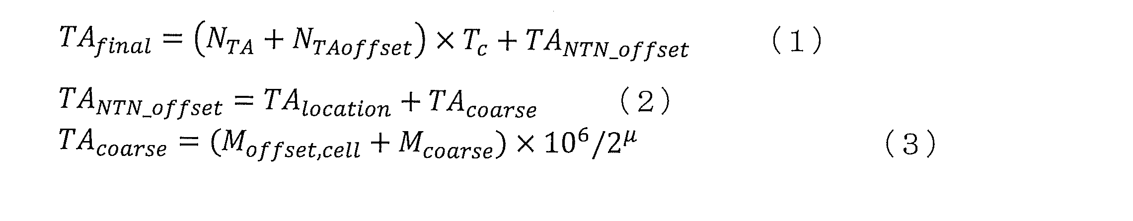

基地局は、PRACHを受信し、基地局基準タイミングとPRACH受信タイミングとの間の差を検出する。基地局は、検出した差に相当するタイミングを補正するためのTAコマンド1(図8におけるFine TAコマンド)を決定し、決定したTAコマンド1を含むPDSCHを送信する。TAコマンド1は、例えば、Rel.15 NRと同様のTAコマンドであってよい。また、S103における、TAコマンド1を含む端末への応答は、RACH応答(RAR)と称されてもよい。 <S103>
The base station receives the PRACH and detects the difference between the base station reference timing and the PRACH reception timing. The base station determines the TA command 1 (Fine TA command in FIG. 8) for correcting the timing corresponding to the detected difference, and transmits the PDSCH including the determined TA command 1. The TA command 1 may be, for example, a TA command similar to Rel.15 NR. Further, the response to the terminal including the TA command 1 in S103 may be referred to as a RACH response (RAR).
端末は、RARによって指定された時間・周波数リソースにおいて、PUSCHを送信する。時間リソースは、基地局からSIBで通知されたKoffset,cellの分、オフセットさせたスロット番号に対応するスロットであり、端末は基地局においてこのスロット番号のスロットで受信されるタイミングで送信する。このとき、端末は、PRACH送信のタイミングから、更に、通知されたTAコマンド1に従ってタイミングを調整する。例えば、式(1)において、NTAにTAコマンド1の値を用いて決定したTAfinalを用いて、タイミング調整を行い、PUSCHを送信する。 <S104>
The terminal transmits PUSCH at the time / frequency resource specified by RAR. The time resource is a slot corresponding to the slot number offset by the amount of K offset, cell notified by the SIB from the base station, and the terminal transmits at the timing of being received in the slot of this slot number at the base station. At this time, the terminal further adjusts the timing from the PRACH transmission timing according to the notified TA command 1. For example, in the formula (1), using a TA final determined using the values of TA commands 1 to N TA, perform timing adjustment, transmits a PUSCH.
基地局は、ランダムアクセスにおける競合解決のための情報及び/又はRRC configuration情報などを、PDSCHを用いて送信する。例えば、基地局は、TAコマンド2(図8におけるCoarse TAコマンド)を含むMAC CEを送信する。TAコマンド2は、例えば、スロット単位の粒度のタイミング調整コマンドである。基地局は、S104において端末から通知されたTA値の情報に基づいて、TAコマンド2を設定する。 <S105>
The base station transmits information for resolving conflicts in random access and / or RRC configuration information using PDSCH. For example, the base station transmits a MAC CE including TA command 2 (Coarse TA command in FIG. 8). The TA command 2 is, for example, a slot-based particle size timing adjustment command. The base station sets the TA command 2 based on the information of the TA value notified from the terminal in S104.
端末は、これ以降のPUSCH及びHARQ-ACK送信に対するタイミング調整において、式(2)のMcoarseをTAコマンド2で通知された値に設定することによって決定したTA値(式(1)のTAfinal)を用いる。 <S106>
The terminal determines the TA value (TA final of equation (1)) determined by setting M coarse of equation (2) to the value notified by TA command 2 in the timing adjustment for subsequent PUSCH and HARQ-ACK transmissions. ) Is used.
衛星及び/又は端末が移動距離の閾値以上移動した場合、端末は、再度、GNSS位置情報及び衛星ephemerisからの位置情報により伝搬遅延を算出し、式(1)のTAlocationを更新して上り送信を行う。なお、TAlocationの更新は、衛星及び/又は端末が閾値以上移動した場合に限らず、例えば、決められた周期で実行されてもよい。あるいは、TAlocationの更新は、衛星及び/又は端末が閾値以上移動した場合と、決められた周期との両方で実行されてもよい。 <S107, S108>
When the satellite and / or the terminal moves beyond the threshold of the moving distance, the terminal again calculates the propagation delay based on the GNSS position information and the position information from the satellite ephemeris , updates the TA location in the equation (1), and transmits the uplink. I do. The update of the TA location is not limited to the case where the satellite and / or the terminal moves by the threshold value or more, and may be executed, for example, at a predetermined cycle. Alternatively, the TA location update may be performed both when the satellite and / or terminal has moved above the threshold and at a fixed period.
基地局は、端末の往復の伝搬遅延量が所定値以上(例えば1スロット以上)変化した場合には、端末のPUSCH及び/又はHARQ-ACKの割り当てスロットを変更するために、TAコマンド2を送信する。 <S109>
When the round-trip propagation delay of the terminal changes by a predetermined value or more (for example, one slot or more), the base station sends TA command 2 to change the PUSCH and / or HARQ-ACK allocation slot of the terminal. do.
本実施の形態2では、パス追従によるタイミング調整を行う。 (Embodiment 2)
In the second embodiment, the timing is adjusted by following the path.
本実施の形態2に係る端末の構成は、実施の形態1に示した端末100の構成と同様であってよい。ただし、実施の形態1に示した端末100のタイミング調整部104における処理が追加される。 [Terminal configuration]
The configuration of the terminal according to the second embodiment may be the same as the configuration of the terminal 100 shown in the first embodiment. However, the processing in the
次に、本実施の形態2におけるタイミング調整について説明する。 [Example of timing adjustment]
Next, the timing adjustment in the second embodiment will be described.

・PRACH送信
・SRS送信
・DRXのスリープ区間(long sleep and/or short sleep)から起床して最初の送信
・TA有効タイマが満了した後の最初の送信
・IDLEまたはINACTIVE状態での送信 The case where the timing adjustment is performed based on the position information, that is, the case where the timing adjustment by path tracking is not performed is, for example, the following case.
・ PRACH transmission ・ SRS transmission ・ First transmission after waking up from DRX sleep section (long sleep and / or short sleep) ・ First transmission after TA valid timer expires ・ Transmission in IDLE or INACTIVE state
・RRC_CONNECTED状態
・スリープから起床後2回目以降の送信 Further, the cases where the timing adjustment based on the position information and the timing adjustment based on the path tracking are performed are, for example, the following cases.
・ RRC_CONNECTED state ・ Transmission after the second time after waking up from sleep
基地局(gNB)は、SSB及びSIBを送信する。SSB及びSIBは、周期的に送信されてよい。SSBには、同期用の信号及びセル固有の基本制御情報が含まれる。また、SIBには、端末が基地局へアクセスするためのセル固有の情報等が含まれる。また、SIBの中に衛星の位置を示す情報(例えば、satellite ephemeris)が含まれてもよい。SIBの中には、セル固有TAオフセット(Cell specific TA offset)が含まれる。 <S201>
The base station (gNB) transmits SSB and SIB. SSB and SIB may be transmitted periodically. The SSB contains signals for synchronization and cell-specific basic control information. In addition, the SIB includes cell-specific information for the terminal to access the base station. In addition, the SIB may include information indicating the position of the satellite (for example, satellite ephemeris). The SIB contains a Cell specific TA offset.
端末は、PRACH送信(図12におけるS102)での位置情報に基づくタイミング調整値TAlocationの算出において、SSB受信タイミング(先頭パスタイミング)を記憶する。そして、端末は、SSB、PDCCH、又は、PDSCHをある間隔で受信し、先頭パスのタイミングの変化をモニタリングする。端末は、ある程度の変化があった場合に、送信タイミングを変更(更新)する。パスのタイミング変化量をΔpathとした場合、端末は、TApath=2×Δpathと決定する。端末は、式(3)において、TApathを含むタイミング調整値のそれぞれを用いてTAfinalを決定し、決定したTAfinalを用いてタイミング調整を行い、PUSCHを送信する。 <S204 and S205>
The terminal stores the SSB reception timing (first path timing) in the calculation of the timing adjustment value TA location based on the position information in the PRACH transmission (S102 in FIG. 12). Then, the terminal receives SSB, PDCCH, or PDSCH at a certain interval and monitors the change in the timing of the first path. The terminal changes (updates) the transmission timing when there is a certain change. When the amount of change in the timing of the path is Δ path, the terminal determines that TA path = 2 × Δ path . In equation (3), the terminal determines the TA final using each of the timing adjustment values including the TA path , adjusts the timing using the determined TA final , and transmits the PUSCH.
端末は、スリープから起床(wake up)した後の最初の送信(例えば、PUSCH送信)において、端末の位置情報を取得する。端末は、衛星の位置が変更している場合には、変更された衛星の位置情報を用いる。そして、端末は、TAlocationを更新して、タイミング調整を行い、PUSCH送信を行う。なお、ここで、端末は、TApathをゼロに設定(リセット又はクリア)する。 <S206>
The terminal acquires the position information of the terminal in the first transmission (for example, PUSCH transmission) after waking up from sleep. When the position of the satellite is changed, the terminal uses the changed position information of the satellite. Then, the terminal updates the TA location , adjusts the timing, and performs PUSCH transmission. Here, the terminal sets (reset or clears) the TA path to zero.
端末は、スリープから起床した後では衛星または端末の位置が変わっている可能性が高いため、タイミング情報(例えば、TA値)を基地局に通知してもよい。また、タイミング情報を基地局に通知するか否かは、衛星の種類(静止衛星、非静止衛星)などにより基地局が指定(SIBで通知)してもよいし、端末の移動速度及び/又は種別などにより端末毎に設定されてもよいし、端末毎に通知されてもよい。 <S207>
Since it is highly possible that the position of the satellite or the terminal has changed after waking up from sleep, the terminal may notify the base station of timing information (for example, TA value). Whether or not to notify the base station of the timing information may be specified by the base station (notified by SIB) depending on the type of satellite (geostationary satellite, non-geostationary satellite), etc., and the moving speed of the terminal and / or It may be set for each terminal depending on the type or the like, or may be notified for each terminal.
S204及びS205と同様に、端末は、パス追従により、TApathを更新する。なお、ここでは、端末は、TAlocationを更新しなくてよい。 <S208 and S209>
Similar to S204 and S205, the terminal updates the TA path by path tracking. Here, the terminal does not have to update the TA location.
3GPPは、100GHzまでの周波数範囲で動作する新無線アクセス技術(NR)の開発を含む第5世代携帯電話技術(単に「5G」ともいう)の次のリリースに向けて作業を続けている。5G規格の初版は2017年の終わりに完成しており、これにより、5G NRの規格に準拠した端末(例えば、スマートフォン)の試作および商用展開に移ることが可能である。 <5G NR system architecture and protocol stack>
3GPP is working towards the next release of fifth-generation mobile phone technology (also simply referred to as "5G"), including the development of a new wireless access technology (NR) that operates in the frequency range up to 100 GHz. The first edition of the 5G standard was completed at the end of 2017, which allows us to move on to prototyping and commercial deployment of terminals (eg, smartphones) that comply with the 5G NR standard.
図14は、NG-RANと5GCとの間の機能分離を示す。NG-RANの論理ノードは、gNBまたはng-eNBである。5GCは、論理ノードAMF、UPF、およびSMFを有する。 <Functional separation between NG-RAN and 5GC in 5G NR>
FIG. 14 shows the functional separation between NG-RAN and 5GC. The logical node of NG-RAN is gNB or ng-eNB. The 5GC has logical nodes AMF, UPF, and SMF.
- 無線ベアラ制御(Radio Bearer Control)、無線アドミッション制御(Radio Admission Control)、接続モビリティ制御(Connection Mobility Control)、上りリンクおよび下りリンクの両方におけるリソースのUEへの動的割当(スケジューリング)等の無線リソース管理(Radio Resource Management)の機能;
- データのIPヘッダ圧縮、暗号化、および完全性保護;
- UEが提供する情報からAMFへのルーティングを決定することができない場合のUEのアタッチ時のAMFの選択;
- UPFに向けたユーザプレーンデータのルーティング;
- AMFに向けた制御プレーン情報のルーティング;
- 接続のセットアップおよび解除;
- ページングメッセージのスケジューリングおよび送信;
- システム報知情報(AMFまたは運用管理保守機能(OAM:Operation, Admission, Maintenance)が発信源)のスケジューリングおよび送信;
- モビリティおよびスケジューリングのための測定および測定報告の設定;
- 上りリンクにおけるトランスポートレベルのパケットマーキング;
- セッション管理;
- ネットワークスライシングのサポート;
- QoSフローの管理およびデータ無線ベアラに対するマッピング;
- RRC_INACTIVE状態のUEのサポート;
- NASメッセージの配信機能;
- 無線アクセスネットワークの共有;
- デュアルコネクティビティ;
- NRとE-UTRAとの緊密な連携。 For example, gNB and ng-eNB host the following main functions:
-Radio Bearer Control, Radio Admission Control, Connection Mobility Control, Dynamic allocation of resources to UEs on both uplink and downlink (scheduling), etc. Radio Resource Management function;
-Data IP header compression, encryption, and integrity protection;
-Selection of AMF when attaching the UE when the routing to AMF cannot be determined from the information provided by the UE;
-Routing user plane data towards UPF;
-Routing control plane information towards AMF;
-Setting up and disconnecting;
-Scheduling and sending paging messages;
-Scheduling and transmission of system notification information (sourced from AMF or Operation, Admission, Maintenance);
-Measurement and measurement reporting settings for mobility and scheduling;
-Transport level packet marking on the uplink;
-Session management;
-Network slicing support;
-Management of QoS flows and mapping to data radio bearers;
-Support for UEs in the RRC_INACIVE state;
-NAS message delivery function;
-Radio access network sharing;
-Dual connectivity;
-Close cooperation between NR and E-UTRA.
- Non-Access Stratum(NAS)シグナリングを終端させる機能;
- NASシグナリングのセキュリティ;
- Access Stratum(AS)のセキュリティ制御;
- 3GPPのアクセスネットワーク間でのモビリティのためのコアネットワーク(CN:Core Network)ノード間シグナリング;
- アイドルモードのUEへの到達可能性(ページングの再送信の制御および実行を含む);
- 登録エリアの管理;
- システム内モビリティおよびシステム間モビリティのサポート;
- アクセス認証;
- ローミング権限のチェックを含むアクセス承認;
- モビリティ管理制御(加入およびポリシー);
- ネットワークスライシングのサポート;
- Session Management Function(SMF)の選択。 The Access and Mobility Management Function (AMF) hosts the following key functions:
-Ability to terminate Non-Access Stratum (NAS) signaling;
-NAS signaling security;
-Access Stratum (AS) security control;
-Core Network (CN) node-to-node signaling for mobility between 3GPP access networks;
-Reachability to UE in idle mode (including control and execution of paging retransmission);
-Registration area management;
-Support for in-system mobility and inter-system mobility;
-Access authentication;
-Access approval including checking roaming authority;
-Mobility management control (subscription and policy);
-Network slicing support;
-Select Session Management Function (SMF).
- intra-RATモビリティ/inter-RATモビリティ(適用可能な場合)のためのアンカーポイント;
- データネットワークとの相互接続のための外部PDU(Protocol Data Unit)セッションポイント;
- パケットのルーティングおよび転送;
- パケット検査およびユーザプレーン部分のポリシールールの強制(Policy rule enforcement);
- トラフィック使用量の報告;
- データネットワークへのトラフィックフローのルーティングをサポートするための上りリンククラス分類(uplink classifier);
- マルチホームPDUセッション(multi-homed PDU session)をサポートするための分岐点(Branching Point);
- ユーザプレーンに対するQoS処理(例えば、パケットフィルタリング、ゲーティング(gating)、UL/DLレート制御(UL/DL rate enforcement);
- 上りリンクトラフィックの検証(SDFのQoSフローに対するマッピング);
- 下りリンクパケットのバッファリングおよび下りリンクデータ通知のトリガ機能。 In addition, the User Plane Function (UPF) hosts the following key functions:
-Anchor points for intra-RAT mobility / inter-RAT mobility (if applicable);
-External PDU (Protocol Data Unit) session point for interconnection with data networks;
-Packet routing and forwarding;
-Policy rule enforcement for packet inspection and user plane parts;
-Traffic usage report;
-Uplink classifier to support the routing of traffic flows to the data network;
-Branching Point to support multi-homed PDU sessions;
-Quos processing for the user plane (eg packet filtering, gating, UL / DL rate enforcement);
-Verification of uplink traffic (mapping of SDF to QoS flow);
-Downlink packet buffering and downlink data notification trigger function.
- セッション管理;
- UEに対するIPアドレスの割当および管理;
- UPFの選択および制御;
- 適切な宛先にトラフィックをルーティングするためのUser Plane Function(UPF)におけるトラフィックステアリング(traffic steering)の設定機能;
- 制御部分のポリシーの強制およびQoS;
- 下りリンクデータの通知。 Finally, the Session Management Function (SMF) hosts the following key functions:
-Session management;
-Assignment and management of IP addresses for UEs;
-UPF selection and control;
-Traffic steering setting function in the User Plane Function (UPF) for routing traffic to the appropriate destination;
-Control policy enforcement and QoS;
-Notification of downlink data.
図15は、NAS部分の、UEがRRC_IDLEからRRC_CONNECTEDに移行する際のUE、gNB、およびAMF(5GCエンティティ)の間のやり取りのいくつかを示す(TS 38.300 v15.6.0参照)。 <Procedure for setting up and reconfiguring RRC connection>
FIG. 15 shows some of the NAS portion of the interaction between the UE, gNB, and AMF (5GC entity) as the UE transitions from RRC_IDLE to RRC_CONNECTED (see TS 38.300 v15.6.0).
図16は、5G NRのためのユースケースのいくつかを示す。3rd generation partnership project new radio(3GPP NR)では、多種多様なサービスおよびアプリケーションをサポートすることがIMT-2020によって構想されていた3つのユースケースが検討されている。大容量・高速通信(eMBB:enhanced mobile-broadband)のための第一段階の仕様の策定が終了している。現在および将来の作業には、eMBBのサポートを拡充していくことに加えて、高信頼・超低遅延通信(URLLC:ultra-reliable and low-latency communications)および多数同時接続マシンタイプ通信(mMTC:massive machine-type communicationsのための標準化が含まれる。図16は、2020年以降のIMTの構想上の利用シナリオのいくつかの例を示す(例えばITU-R M.2083 図14参照)。 <IMT usage scenario after 2020>
FIG. 16 shows some of the use cases for 5G NR. The 3rd generation partnership project new radio (3GPP NR) is considering three use cases envisioned by IMT-2020 to support a wide variety of services and applications. The first-stage specifications for high-capacity, high-speed communication (eMBB: enhanced mobile-broadband) have been completed. For current and future work, in addition to expanding eMBB support, high-reliability, ultra-reliable and low-latency communications (URLLC) and multiple simultaneous machine type communications (mMTTC:) Standardization for massive machine-type communications is included. FIG. 16 shows some examples of conceptual use scenarios for IMT since 2020 (see, eg, ITU-RM. 2083, FIG. 14).
5GのQoS(Quality of Service)モデルは、QoSフローに基づいており、保証されたフロービットレートが求められるQoSフロー(GBR:Guaranteed Bit Rate QoSフロー)、および、保証されたフロービットレートが求められないQoSフロー(非GBR QoSフロー)をいずれもサポートする。したがって、NASレベルでは、QoSフローは、PDUセッションにおける最も微細な粒度のQoSの区分である。QoSフローは、NG-Uインタフェースを介してカプセル化ヘッダ(encapsulation header)において搬送されるQoSフローID(QFI:QoS Flow ID)によってPDUセッション内で特定される。 <QoS control>
The 5G Quality of Service (QoS) model is based on QoS flow, and QoS flow (GBR: Guaranteed Bit Rate QoS flow), which requires a guaranteed flow bit rate, and guaranteed flow bit rate are required. Supports none of QoS flows (non-GBR QoS flows). Therefore, at the NAS level, QoS flow is the finest grain size QoS segment in a PDU session. The quality of service ID (QFI) is identified in the PDU session by the quality of service ID (QFI) carried in the encapsulation header via the NG-U interface.
101 PRACH生成部
102,206 データ生成部
103 位置情報取得部
104 タイミング調整部
105,208 無線送信部
106,201 アンテナ
107,202 無線受信部
108 復調・復号部
109,209 制御部
200 基地局
203 データ受信処理部
204 PRACH検出部
205 タイミング情報生成部
207 データ送信処理部
Claims (6)
- 信号の送信単位における前記信号の送信タイミングの制御に関する第1の情報と、前記送信単位よりも細かい単位における前記送信タイミングの制御に関する第2の情報とに基づいて、送信タイミングを制御する制御回路と、
前記制御回路による前記送信タイミングの制御に基づいて、信号送信を行う送信回路と、
を具備する送信装置。 A control circuit that controls the transmission timing based on the first information regarding the control of the transmission timing of the signal in the signal transmission unit and the second information regarding the control of the transmission timing in a unit finer than the transmission unit. ,
A transmission circuit that transmits signals based on the control of the transmission timing by the control circuit, and
A transmitter equipped with. - 前記第1の情報は、セル固有の第3の情報、前記送信装置固有の第4の情報及びタイミング制御を指示する第5の情報の少なくとも1つである、
請求項1に記載の送信装置。 The first information is at least one of a cell-specific third information, a transmission device-specific fourth information, and a fifth information instructing timing control.
The transmitting device according to claim 1. - 前記第2の情報は、前記送信装置の位置と前記送信装置の通信相手である受信装置の位置とに基づいて決定した第6の情報、前記送信装置に到達する信号のパス到来タイミングから決定した第7の情報、及び、タイミング制御を指示する第8の情報の少なくとも1つである、
請求項1に記載の送信装置。 The second information is determined from the sixth information determined based on the position of the transmitting device and the position of the receiving device which is the communication partner of the transmitting device, and the path arrival timing of the signal reaching the transmitting device. At least one of the seventh piece of information and the eighth piece of information instructing timing control.
The transmitting device according to claim 1. - 前記送信回路は、前記送信装置の位置、前記受信装置の位置、及び、前記第1の値の変化の少なくとも1つが閾値以上の場合、前記第8の情報に関する情報を、前記受信装置に送信する、
請求項3に記載の送信装置。 When at least one of the position of the transmitting device, the position of the receiving device, and the change of the first value is equal to or more than a threshold value, the transmitting circuit transmits information regarding the eighth information to the receiving device. ,
The transmitter according to claim 3. - 前記第8の情報に関する情報は、前記第8の情報、前記送信装置の位置情報、及び、前記受信装置の位置情報の少なくとも1つである、
請求項4に記載の送信装置。 The information regarding the eighth information is at least one of the eighth information, the position information of the transmitting device, and the position information of the receiving device.
The transmitting device according to claim 4. - 送信装置が、
信号の送信単位における前記信号の送信タイミングの制御に関する第1の情報と、前記送信単位よりも細かい単位における前記送信タイミングの制御に関する第2の情報とに基づいて、送信タイミングを制御し、
前記送信タイミングの制御に基づいて、信号送信を行う、
送信方法。 The transmitter is
The transmission timing is controlled based on the first information regarding the control of the transmission timing of the signal in the transmission unit of the signal and the second information regarding the control of the transmission timing in a unit finer than the transmission unit.
Signal transmission is performed based on the control of the transmission timing.
Sending method.
Priority Applications (9)
| Application Number | Priority Date | Filing Date | Title |
|---|---|---|---|
| US17/798,266 US20230049008A1 (en) | 2020-02-13 | 2021-01-14 | Transmission device and transmission method |
| JP2022500273A JPWO2021161710A5 (en) | 2021-01-14 | Transmission device, communication method, and integrated circuit | |
| CA3170163A CA3170163A1 (en) | 2020-02-13 | 2021-01-14 | Transmission device and transmission method |
| EP21753984.0A EP4106424A4 (en) | 2020-02-13 | 2021-01-14 | Transmission device and transmission method |
| MX2022009387A MX2022009387A (en) | 2020-02-13 | 2021-01-14 | Transmission device and transmission method. |
| KR1020227027122A KR20220140724A (en) | 2020-02-13 | 2021-01-14 | Transmitting device and transmitting method |
| CN202180014049.0A CN115088322A (en) | 2020-02-13 | 2021-01-14 | Transmission device and transmission method |
| BR112022015881A BR112022015881A2 (en) | 2020-02-13 | 2021-01-14 | TRANSMISSION DEVICE AND TRANSMISSION METHOD |
| CONC2022/0010652A CO2022010652A2 (en) | 2020-02-13 | 2022-07-29 | Transmission device and transmission method |
Applications Claiming Priority (2)
| Application Number | Priority Date | Filing Date | Title |
|---|---|---|---|
| JP2020022772 | 2020-02-13 | ||
| JP2020-022772 | 2020-02-13 |
Publications (1)
| Publication Number | Publication Date |
|---|---|
| WO2021161710A1 true WO2021161710A1 (en) | 2021-08-19 |
Family
ID=77292993
Family Applications (1)
| Application Number | Title | Priority Date | Filing Date |
|---|---|---|---|
| PCT/JP2021/000939 WO2021161710A1 (en) | 2020-02-13 | 2021-01-14 | Transmission device and transmission method |
Country Status (9)
| Country | Link |
|---|---|
| US (1) | US20230049008A1 (en) |
| EP (1) | EP4106424A4 (en) |
| KR (1) | KR20220140724A (en) |
| CN (1) | CN115088322A (en) |
| BR (1) | BR112022015881A2 (en) |
| CA (1) | CA3170163A1 (en) |
| CO (1) | CO2022010652A2 (en) |
| MX (1) | MX2022009387A (en) |
| WO (1) | WO2021161710A1 (en) |
Cited By (3)
| Publication number | Priority date | Publication date | Assignee | Title |
|---|---|---|---|---|
| WO2022091557A1 (en) * | 2020-10-29 | 2022-05-05 | 株式会社Nttドコモ | Terminal, base station and communication method |
| WO2023042319A1 (en) * | 2021-09-15 | 2023-03-23 | 株式会社Nttドコモ | Terminal and communication method |
| WO2023151098A1 (en) * | 2022-02-14 | 2023-08-17 | 北京小米移动软件有限公司 | Method and apparatus for transmitting system information, and readable storage medium |
Families Citing this family (2)
| Publication number | Priority date | Publication date | Assignee | Title |
|---|---|---|---|---|
| US11889450B2 (en) * | 2020-05-06 | 2024-01-30 | Qualcomm Incorporated | Techniques for compensating timing advance for full duplex communication |
| EP4197263A1 (en) * | 2020-10-15 | 2023-06-21 | FG Innovation Company Limited | Mac-ce command action timing control in non-terrestrial networks |
Citations (1)
| Publication number | Priority date | Publication date | Assignee | Title |
|---|---|---|---|---|
| JP2020022772A (en) | 2013-09-24 | 2020-02-13 | アダージョ メディカル インコーポレイテッドAdagio Medical,Inc. | Freezing ablation system |
Family Cites Families (3)
| Publication number | Priority date | Publication date | Assignee | Title |
|---|---|---|---|---|
| CN109644493A (en) * | 2016-06-15 | 2019-04-16 | 康维达无线有限责任公司 | Without permit operation |
| CN111149394B (en) * | 2017-12-06 | 2022-01-25 | 上海朗帛通信技术有限公司 | Method and device in communication node for wireless communication |
| KR20210005004A (en) * | 2018-04-03 | 2021-01-13 | 아이디에이씨 홀딩스, 인크. | Timing advance for non-terrestrial network communication |
-
2021
- 2021-01-14 US US17/798,266 patent/US20230049008A1/en active Pending
- 2021-01-14 BR BR112022015881A patent/BR112022015881A2/en unknown
- 2021-01-14 WO PCT/JP2021/000939 patent/WO2021161710A1/en unknown
- 2021-01-14 EP EP21753984.0A patent/EP4106424A4/en active Pending
- 2021-01-14 CA CA3170163A patent/CA3170163A1/en active Pending
- 2021-01-14 CN CN202180014049.0A patent/CN115088322A/en active Pending
- 2021-01-14 MX MX2022009387A patent/MX2022009387A/en unknown
- 2021-01-14 KR KR1020227027122A patent/KR20220140724A/en active Search and Examination
-
2022
- 2022-07-29 CO CONC2022/0010652A patent/CO2022010652A2/en unknown
Patent Citations (1)
| Publication number | Priority date | Publication date | Assignee | Title |
|---|---|---|---|---|
| JP2020022772A (en) | 2013-09-24 | 2020-02-13 | アダージョ メディカル インコーポレイテッドAdagio Medical,Inc. | Freezing ablation system |
Non-Patent Citations (8)
| Title |
|---|
| "Medium Access Control (MAC) protocol specification (Release 15", 3GPP, TS 38.321 |
| "Solutions for NR to support non-terrestrial networks (NTN) (Release 16", 3GPP, TR 38.821 |
| 3GPP TS 38.211 |
| 3GPP TS 38.300 |
| ERICSSON: "Remaining details on Random access for NTN", 3GPP DRAFT; R2-1915567, vol. RAN WG2, 7 November 2019 (2019-11-07), Reno, Nevada, US, pages 1 - 7, XP051815978 * |
| MEDIATEK INC: "Doppler, Timing Advance and RACH in NR-NTN", 3GPP DRAFT; R1-1906464-MEDIATEK-DOPPLER, TA AND RACH IN NR-NTN, vol. RAN WG1, 2 May 2019 (2019-05-02), Reno, Nevada, USA, pages 1 - 8, XP051708499 * |
| MEDIATEK INC: "Physical layer control procedure in NR-NTN", 3GPP DRAFT; R1-1908014-MEDIATEK-PHYSICAL LAYER CONTROL PROCEDURE IN NR NTN, vol. RAN WG1, 16 August 2019 (2019-08-16), Prague, Czech Republic, pages 1 - 5, XP051764637 * |
| PANASONIC: "Timing advance and PRACH design for NTN", 3GPP DRAFT; R1-1912903, vol. RAN WG1, 8 November 2019 (2019-11-08), Reno, USA, pages 1 - 13, XP051820238 * |
Cited By (3)
| Publication number | Priority date | Publication date | Assignee | Title |
|---|---|---|---|---|
| WO2022091557A1 (en) * | 2020-10-29 | 2022-05-05 | 株式会社Nttドコモ | Terminal, base station and communication method |
| WO2023042319A1 (en) * | 2021-09-15 | 2023-03-23 | 株式会社Nttドコモ | Terminal and communication method |
| WO2023151098A1 (en) * | 2022-02-14 | 2023-08-17 | 北京小米移动软件有限公司 | Method and apparatus for transmitting system information, and readable storage medium |
Also Published As
| Publication number | Publication date |
|---|---|
| KR20220140724A (en) | 2022-10-18 |
| CN115088322A (en) | 2022-09-20 |
| EP4106424A1 (en) | 2022-12-21 |
| CO2022010652A2 (en) | 2022-08-19 |
| US20230049008A1 (en) | 2023-02-16 |
| CA3170163A1 (en) | 2021-08-19 |
| EP4106424A4 (en) | 2023-07-19 |
| BR112022015881A2 (en) | 2022-10-04 |
| MX2022009387A (en) | 2022-09-07 |
| JPWO2021161710A1 (en) | 2021-08-19 |
Similar Documents
| Publication | Publication Date | Title |
|---|---|---|
| WO2021161710A1 (en) | Transmission device and transmission method | |
| WO2021161639A1 (en) | Reception device, transmission device, reception method, and transmission method | |
| US20230053871A1 (en) | Beam failure recovery for single dci-based m-trp urllc transmissions | |
| CN115606141A (en) | Communication device and base station | |
| WO2022085252A1 (en) | Terminal, base station, transmitting method, and receiving method | |
| CN113875288A (en) | Transceiver device and base station | |
| WO2021131307A1 (en) | Communication device and communication method | |
| KR20240005935A (en) | User equipment, scheduling node, method for user equipment and method for scheduling node | |
| CN116349393A (en) | Optimizing system information acquisition for NR devices | |
| JP2023514076A (en) | Communication device and communication method using reserved resources | |
| WO2022030059A1 (en) | Terminal, base station, and communication method | |
| WO2023203740A1 (en) | Terminal, base station, and communication method | |
| WO2023153011A1 (en) | Terminal, base station, and communication method | |
| WO2022208990A1 (en) | Terminal, base station, and communication method | |
| WO2024070402A1 (en) | Terminal, base station, communication method, and integrated circuit | |
| WO2022024427A1 (en) | Terminal and communication method | |
| WO2024034199A1 (en) | Base station, terminal, and communication method | |
| JP2023553174A (en) | NTN entities, user equipment and base stations involved in the transmission procedure | |
| WO2023132786A2 (en) | Advance indication of resource selection | |
| WO2023152368A1 (en) | Non-terrestrial network epoch time indication considering sfn cycle | |
| KR20240041920A (en) | Communication device and communication method for allocating one or more additional operating windows for sidelink signals | |
| JP2023536970A (en) | Transceiver equipment, network entities and base stations | |
| KR20240046556A (en) | Sidelink discontinuous reception operation method and device |
Legal Events
| Date | Code | Title | Description |
|---|---|---|---|
| 121 | Ep: the epo has been informed by wipo that ep was designated in this application |
Ref document number: 21753984 Country of ref document: EP Kind code of ref document: A1 |
|
| ENP | Entry into the national phase |
Ref document number: 2022500273 Country of ref document: JP Kind code of ref document: A |
|
| ENP | Entry into the national phase |
Ref document number: 3170163 Country of ref document: CA |
|
| REG | Reference to national code |
Ref country code: BR Ref legal event code: B01A Ref document number: 112022015881 Country of ref document: BR |
|
| NENP | Non-entry into the national phase |
Ref country code: DE |
|
| ENP | Entry into the national phase |
Ref document number: 2021753984 Country of ref document: EP Effective date: 20220913 |
|
| ENP | Entry into the national phase |
Ref document number: 112022015881 Country of ref document: BR Kind code of ref document: A2 Effective date: 20220810 |