WO2022080311A1 - 方向・流量制御弁および液圧システム - Google Patents
方向・流量制御弁および液圧システム Download PDFInfo
- Publication number
- WO2022080311A1 WO2022080311A1 PCT/JP2021/037565 JP2021037565W WO2022080311A1 WO 2022080311 A1 WO2022080311 A1 WO 2022080311A1 JP 2021037565 W JP2021037565 W JP 2021037565W WO 2022080311 A1 WO2022080311 A1 WO 2022080311A1
- Authority
- WO
- WIPO (PCT)
- Prior art keywords
- annular groove
- spool
- electromagnetic proportional
- port
- proportional valve
- Prior art date
Links
- 230000007935 neutral effect Effects 0.000 claims description 16
- 230000002093 peripheral effect Effects 0.000 claims description 10
- 239000010720 hydraulic oil Substances 0.000 description 12
- 238000012986 modification Methods 0.000 description 12
- 230000004048 modification Effects 0.000 description 12
- 238000010586 diagram Methods 0.000 description 4
- 230000000903 blocking effect Effects 0.000 description 3
- 230000000694 effects Effects 0.000 description 3
- 238000004904 shortening Methods 0.000 description 2
- 238000006073 displacement reaction Methods 0.000 description 1
- 239000012530 fluid Substances 0.000 description 1
- 238000000034 method Methods 0.000 description 1
Images


Classifications
-
- F—MECHANICAL ENGINEERING; LIGHTING; HEATING; WEAPONS; BLASTING
- F15—FLUID-PRESSURE ACTUATORS; HYDRAULICS OR PNEUMATICS IN GENERAL
- F15B—SYSTEMS ACTING BY MEANS OF FLUIDS IN GENERAL; FLUID-PRESSURE ACTUATORS, e.g. SERVOMOTORS; DETAILS OF FLUID-PRESSURE SYSTEMS, NOT OTHERWISE PROVIDED FOR
- F15B13/00—Details of servomotor systems ; Valves for servomotor systems
- F15B13/02—Fluid distribution or supply devices characterised by their adaptation to the control of servomotors
- F15B13/04—Fluid distribution or supply devices characterised by their adaptation to the control of servomotors for use with a single servomotor
- F15B13/042—Fluid distribution or supply devices characterised by their adaptation to the control of servomotors for use with a single servomotor operated by fluid pressure
- F15B13/043—Fluid distribution or supply devices characterised by their adaptation to the control of servomotors for use with a single servomotor operated by fluid pressure with electrically-controlled pilot valves
- F15B13/0433—Fluid distribution or supply devices characterised by their adaptation to the control of servomotors for use with a single servomotor operated by fluid pressure with electrically-controlled pilot valves the pilot valves being pressure control valves
-
- F—MECHANICAL ENGINEERING; LIGHTING; HEATING; WEAPONS; BLASTING
- F16—ENGINEERING ELEMENTS AND UNITS; GENERAL MEASURES FOR PRODUCING AND MAINTAINING EFFECTIVE FUNCTIONING OF MACHINES OR INSTALLATIONS; THERMAL INSULATION IN GENERAL
- F16K—VALVES; TAPS; COCKS; ACTUATING-FLOATS; DEVICES FOR VENTING OR AERATING
- F16K11/00—Multiple-way valves, e.g. mixing valves; Pipe fittings incorporating such valves
- F16K11/02—Multiple-way valves, e.g. mixing valves; Pipe fittings incorporating such valves with all movable sealing faces moving as one unit
- F16K11/06—Multiple-way valves, e.g. mixing valves; Pipe fittings incorporating such valves with all movable sealing faces moving as one unit comprising only sliding valves, i.e. sliding closure elements
- F16K11/065—Multiple-way valves, e.g. mixing valves; Pipe fittings incorporating such valves with all movable sealing faces moving as one unit comprising only sliding valves, i.e. sliding closure elements with linearly sliding closure members
- F16K11/07—Multiple-way valves, e.g. mixing valves; Pipe fittings incorporating such valves with all movable sealing faces moving as one unit comprising only sliding valves, i.e. sliding closure elements with linearly sliding closure members with cylindrical slides
-
- F—MECHANICAL ENGINEERING; LIGHTING; HEATING; WEAPONS; BLASTING
- F16—ENGINEERING ELEMENTS AND UNITS; GENERAL MEASURES FOR PRODUCING AND MAINTAINING EFFECTIVE FUNCTIONING OF MACHINES OR INSTALLATIONS; THERMAL INSULATION IN GENERAL
- F16K—VALVES; TAPS; COCKS; ACTUATING-FLOATS; DEVICES FOR VENTING OR AERATING
- F16K11/00—Multiple-way valves, e.g. mixing valves; Pipe fittings incorporating such valves
- F16K11/10—Multiple-way valves, e.g. mixing valves; Pipe fittings incorporating such valves with two or more closure members not moving as a unit
- F16K11/20—Multiple-way valves, e.g. mixing valves; Pipe fittings incorporating such valves with two or more closure members not moving as a unit operated by separate actuating members
- F16K11/207—Multiple-way valves, e.g. mixing valves; Pipe fittings incorporating such valves with two or more closure members not moving as a unit operated by separate actuating members with two handles or actuating mechanisms at opposite sides of the housing
-
- F—MECHANICAL ENGINEERING; LIGHTING; HEATING; WEAPONS; BLASTING
- F16—ENGINEERING ELEMENTS AND UNITS; GENERAL MEASURES FOR PRODUCING AND MAINTAINING EFFECTIVE FUNCTIONING OF MACHINES OR INSTALLATIONS; THERMAL INSULATION IN GENERAL
- F16K—VALVES; TAPS; COCKS; ACTUATING-FLOATS; DEVICES FOR VENTING OR AERATING
- F16K11/00—Multiple-way valves, e.g. mixing valves; Pipe fittings incorporating such valves
- F16K11/10—Multiple-way valves, e.g. mixing valves; Pipe fittings incorporating such valves with two or more closure members not moving as a unit
- F16K11/20—Multiple-way valves, e.g. mixing valves; Pipe fittings incorporating such valves with two or more closure members not moving as a unit operated by separate actuating members
- F16K11/22—Multiple-way valves, e.g. mixing valves; Pipe fittings incorporating such valves with two or more closure members not moving as a unit operated by separate actuating members with an actuating member for each valve, e.g. interconnected to form multiple-way valves
-
- F—MECHANICAL ENGINEERING; LIGHTING; HEATING; WEAPONS; BLASTING
- F16—ENGINEERING ELEMENTS AND UNITS; GENERAL MEASURES FOR PRODUCING AND MAINTAINING EFFECTIVE FUNCTIONING OF MACHINES OR INSTALLATIONS; THERMAL INSULATION IN GENERAL
- F16K—VALVES; TAPS; COCKS; ACTUATING-FLOATS; DEVICES FOR VENTING OR AERATING
- F16K27/00—Construction of housing; Use of materials therefor
- F16K27/04—Construction of housing; Use of materials therefor of sliding valves
- F16K27/041—Construction of housing; Use of materials therefor of sliding valves cylindrical slide valves
-
- F—MECHANICAL ENGINEERING; LIGHTING; HEATING; WEAPONS; BLASTING
- F16—ENGINEERING ELEMENTS AND UNITS; GENERAL MEASURES FOR PRODUCING AND MAINTAINING EFFECTIVE FUNCTIONING OF MACHINES OR INSTALLATIONS; THERMAL INSULATION IN GENERAL
- F16K—VALVES; TAPS; COCKS; ACTUATING-FLOATS; DEVICES FOR VENTING OR AERATING
- F16K3/00—Gate valves or sliding valves, i.e. cut-off apparatus with closing members having a sliding movement along the seat for opening and closing
- F16K3/30—Details
- F16K3/314—Forms or constructions of slides; Attachment of the slide to the spindle
-
- F—MECHANICAL ENGINEERING; LIGHTING; HEATING; WEAPONS; BLASTING
- F16—ENGINEERING ELEMENTS AND UNITS; GENERAL MEASURES FOR PRODUCING AND MAINTAINING EFFECTIVE FUNCTIONING OF MACHINES OR INSTALLATIONS; THERMAL INSULATION IN GENERAL
- F16K—VALVES; TAPS; COCKS; ACTUATING-FLOATS; DEVICES FOR VENTING OR AERATING
- F16K31/00—Actuating devices; Operating means; Releasing devices
- F16K31/12—Actuating devices; Operating means; Releasing devices actuated by fluid
- F16K31/122—Actuating devices; Operating means; Releasing devices actuated by fluid the fluid acting on a piston
- F16K31/1225—Actuating devices; Operating means; Releasing devices actuated by fluid the fluid acting on a piston with a plurality of pistons
-
- F—MECHANICAL ENGINEERING; LIGHTING; HEATING; WEAPONS; BLASTING
- F15—FLUID-PRESSURE ACTUATORS; HYDRAULICS OR PNEUMATICS IN GENERAL
- F15B—SYSTEMS ACTING BY MEANS OF FLUIDS IN GENERAL; FLUID-PRESSURE ACTUATORS, e.g. SERVOMOTORS; DETAILS OF FLUID-PRESSURE SYSTEMS, NOT OTHERWISE PROVIDED FOR
- F15B2211/00—Circuits for servomotor systems
- F15B2211/30—Directional control
- F15B2211/305—Directional control characterised by the type of valves
- F15B2211/3056—Assemblies of multiple valves
- F15B2211/30565—Assemblies of multiple valves having multiple valves for a single output member, e.g. for creating higher valve function by use of multiple valves like two 2/2-valves replacing a 5/3-valve
- F15B2211/3057—Assemblies of multiple valves having multiple valves for a single output member, e.g. for creating higher valve function by use of multiple valves like two 2/2-valves replacing a 5/3-valve having two valves, one for each port of a double-acting output member
-
- F—MECHANICAL ENGINEERING; LIGHTING; HEATING; WEAPONS; BLASTING
- F15—FLUID-PRESSURE ACTUATORS; HYDRAULICS OR PNEUMATICS IN GENERAL
- F15B—SYSTEMS ACTING BY MEANS OF FLUIDS IN GENERAL; FLUID-PRESSURE ACTUATORS, e.g. SERVOMOTORS; DETAILS OF FLUID-PRESSURE SYSTEMS, NOT OTHERWISE PROVIDED FOR
- F15B2211/00—Circuits for servomotor systems
- F15B2211/30—Directional control
- F15B2211/32—Directional control characterised by the type of actuation
- F15B2211/327—Directional control characterised by the type of actuation electrically or electronically
-
- F—MECHANICAL ENGINEERING; LIGHTING; HEATING; WEAPONS; BLASTING
- F15—FLUID-PRESSURE ACTUATORS; HYDRAULICS OR PNEUMATICS IN GENERAL
- F15B—SYSTEMS ACTING BY MEANS OF FLUIDS IN GENERAL; FLUID-PRESSURE ACTUATORS, e.g. SERVOMOTORS; DETAILS OF FLUID-PRESSURE SYSTEMS, NOT OTHERWISE PROVIDED FOR
- F15B2211/00—Circuits for servomotor systems
- F15B2211/30—Directional control
- F15B2211/32—Directional control characterised by the type of actuation
- F15B2211/329—Directional control characterised by the type of actuation actuated by fluid pressure
-
- F—MECHANICAL ENGINEERING; LIGHTING; HEATING; WEAPONS; BLASTING
- F15—FLUID-PRESSURE ACTUATORS; HYDRAULICS OR PNEUMATICS IN GENERAL
- F15B—SYSTEMS ACTING BY MEANS OF FLUIDS IN GENERAL; FLUID-PRESSURE ACTUATORS, e.g. SERVOMOTORS; DETAILS OF FLUID-PRESSURE SYSTEMS, NOT OTHERWISE PROVIDED FOR
- F15B2211/00—Circuits for servomotor systems
- F15B2211/30—Directional control
- F15B2211/355—Pilot pressure control
-
- F—MECHANICAL ENGINEERING; LIGHTING; HEATING; WEAPONS; BLASTING
- F15—FLUID-PRESSURE ACTUATORS; HYDRAULICS OR PNEUMATICS IN GENERAL
- F15B—SYSTEMS ACTING BY MEANS OF FLUIDS IN GENERAL; FLUID-PRESSURE ACTUATORS, e.g. SERVOMOTORS; DETAILS OF FLUID-PRESSURE SYSTEMS, NOT OTHERWISE PROVIDED FOR
- F15B2211/00—Circuits for servomotor systems
- F15B2211/60—Circuit components or control therefor
- F15B2211/63—Electronic controllers
- F15B2211/6303—Electronic controllers using input signals
- F15B2211/6346—Electronic controllers using input signals representing a state of input means, e.g. joystick position
-
- F—MECHANICAL ENGINEERING; LIGHTING; HEATING; WEAPONS; BLASTING
- F15—FLUID-PRESSURE ACTUATORS; HYDRAULICS OR PNEUMATICS IN GENERAL
- F15B—SYSTEMS ACTING BY MEANS OF FLUIDS IN GENERAL; FLUID-PRESSURE ACTUATORS, e.g. SERVOMOTORS; DETAILS OF FLUID-PRESSURE SYSTEMS, NOT OTHERWISE PROVIDED FOR
- F15B2211/00—Circuits for servomotor systems
- F15B2211/60—Circuit components or control therefor
- F15B2211/635—Circuits providing pilot pressure to pilot pressure-controlled fluid circuit elements
- F15B2211/6355—Circuits providing pilot pressure to pilot pressure-controlled fluid circuit elements having valve means
-
- F—MECHANICAL ENGINEERING; LIGHTING; HEATING; WEAPONS; BLASTING
- F15—FLUID-PRESSURE ACTUATORS; HYDRAULICS OR PNEUMATICS IN GENERAL
- F15B—SYSTEMS ACTING BY MEANS OF FLUIDS IN GENERAL; FLUID-PRESSURE ACTUATORS, e.g. SERVOMOTORS; DETAILS OF FLUID-PRESSURE SYSTEMS, NOT OTHERWISE PROVIDED FOR
- F15B2211/00—Circuits for servomotor systems
- F15B2211/60—Circuit components or control therefor
- F15B2211/67—Methods for controlling pilot pressure
-
- F—MECHANICAL ENGINEERING; LIGHTING; HEATING; WEAPONS; BLASTING
- F16—ENGINEERING ELEMENTS AND UNITS; GENERAL MEASURES FOR PRODUCING AND MAINTAINING EFFECTIVE FUNCTIONING OF MACHINES OR INSTALLATIONS; THERMAL INSULATION IN GENERAL
- F16K—VALVES; TAPS; COCKS; ACTUATING-FLOATS; DEVICES FOR VENTING OR AERATING
- F16K2200/00—Details of valves
- F16K2200/30—Spring arrangements
Definitions
- the present disclosure relates to a directional / flow rate control valve for a hydraulic actuator that operates in both directions, and a hydraulic system including the directional / flow rate control valve.
- a directional / flow rate control valve containing multiple spools may be used for the hydraulic actuator that operates in both directions.
- Each spool opens and closes between specific ports, and the opening area between the ports (that is, the flow rate of the hydraulic fluid) changes according to the amount of movement of the spool.
- Patent Document 1 a direction / flow rate control valve 100 arranged between the hydraulic cylinder 120 and the hydraulic pump 110 (referred to as “independent metering valve” in Patent Document 1). ) Is disclosed.
- the direction / flow rate control valve 100 has a pump port 101, a pair of supply / discharge ports 102 and 103, and a tank port 104. Further, the direction / flow rate control valve 100 includes a first spool 130 that opens and closes between the pump port 101 and the supply / discharge port 102, a second spool 140 that opens and closes between the supply / discharge port 102 and the tank port 104, and a pump port. It includes a third spool 150 that opens and closes between the supply / discharge port 103 and the supply / discharge port 103, and a fourth spool 160 that opens and closes between the supply / discharge port 103 and the tank port 104. With such a configuration, independent metering control is possible on the meter-in side or the meter-out side regardless of which direction the hydraulic cylinder 120 operates.
- Patent Document 1 describes "electro-hydraulic displacement control" for the first to fourth spools 130 to 160. It is presumed that this means that the electric signal is converted into a pilot pressure, and the pilot pressure causes the spool to be displaced. In such a configuration, an electromagnetic proportional valve is generally used. That is, the direction / flow rate control valve 100 of Patent Document 1 requires four electromagnetic proportional valves. The electromagnetic proportional valve may be incorporated in the direction / flow rate control valve 100, or may be connected to the direction / flow rate control valve 100 by piping.
- an object of the present disclosure is to provide a directional / flow rate control valve capable of independent metering control with a small number of electromagnetic proportional valves, and a hydraulic pressure system including the directional / flow rate control valve.
- the direction / flow rate control valve of the present disclosure has a pump port, a first supply / discharge port, a second supply / discharge port and a tank port, and internally has a first pilot chamber and a second pilot chamber. It has a housing in which a third pilot chamber is formed, a first end surface facing the first pilot chamber, and a second end surface facing the third pilot chamber, and the first supply / discharge port is the pump port and the pump port.
- a first spool that shuts off from both of the tank ports or communicates the first supply / discharge port with either the pump port or the tank port, and a second spool that is independent of the first spool.
- the second end surface facing the second pilot chamber and the second end surface facing the third pilot chamber are provided, and the second supply / discharge port is blocked from both the pump port and the tank port, or the tank port is blocked. It is characterized by comprising a second spool for communicating the second supply / discharge port with the other of the pump port and the tank port.
- the hydraulic actuator connected to the first supply / discharge port and the second supply / discharge port can be operated in both directions by using the two spools, the first spool and the second spool. Further, since the first spool and the second spool are independent of each other, the first spool can be moved according to the pressure difference between the first pilot chamber and the third pilot chamber, and the second pilot chamber and the second spool can be moved. 3 The second spool can be moved according to the pressure difference with the pilot chamber. As a result, independent metering control is possible on the meter-in side or the meter-out side regardless of which direction the hydraulic actuator operates. Further, since the number of pilot chambers is three, the number of electromagnetic proportional valves required can be reduced to three.
- the hydraulic pressure system of the present disclosure includes the above-mentioned direction / flow control valve, a hydraulic pump connected to the pump port of the direction / flow control valve, and the first supply / discharge of the direction / flow control valve.
- a hydraulic actuator that operates in the first and second directions connected to the port and the second supply / discharge port, and a first electromagnetic proportional valve that regulates the pressure in the first pilot chamber of the direction / flow control valve.
- a second electromagnetic proportional valve that adjusts the pressure in the second pilot chamber of the direction / flow control valve, and a third electromagnetic proportional valve that adjusts the pressure in the third pilot chamber of the direction / flow control valve. It is characterized by comprising the first electromagnetic proportional valve, the second electromagnetic proportional valve, and a control device for controlling the third electromagnetic proportional valve.
- a directional / flow rate control valve capable of independent metering control with a small number of electromagnetic proportional valves is provided.
- FIG. 3 is a schematic configuration diagram of a hydraulic pressure system including a direction / flow rate control valve of FIG. It is a figure which shows the operation of the direction / flow rate control valve of FIG. 1 when the hydraulic actuator is operated in the 1st direction. It is a figure which shows the operation of the direction / flow rate control valve of FIG. 1 when the hydraulic actuator is operated in the 2nd direction. It is a schematic block diagram of the hydraulic system when the shape of the 1st spool and the shape of the 2nd spool are exchanged. It is sectional drawing of the direction
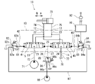
- FIG. 1 shows a direction / flow rate control valve 1 according to an embodiment
- FIG. 2 shows a hydraulic pressure system 10 including the direction / flow rate control valve 1.
- the direction / flow rate control valve 1 is arranged between the hydraulic actuator 73 and the hydraulic pump 71 that operate in the first direction A and the second direction B.
- the hydraulic actuator 73 is a single-rod hydraulic cylinder
- the first direction A is the shortening direction
- the second direction B is the extension direction.
- the first direction A may be the extension direction
- the second direction B may be the shortening direction.
- the hydraulic actuator may be a hydraulic cylinder of both rods or a hydraulic motor.
- the direction / flow rate control valve 1 includes a housing 2 and a first spool 5 and a second spool 6 slidably held by the housing 2.
- the first spool 5 and the second spool 6 are independent of each other.
- the housing 2 has a pump port 11, a first supply / discharge port 12, a second supply / discharge port 13, and a tank port 14 on the surface. Further, the housing 2 has a first pilot port 42, a second pilot port 46, and a third pilot port 27 on the surface. Further, inside the housing 2, a first pilot chamber 41, a second pilot chamber 45, and a third pilot chamber 25 are formed.
- the housing 2 includes a rectangular parallelepiped housing body 3 and a first cover 4A and a second cover 4B attached to both side surfaces of the housing body 3, respectively.
- the first cover 4A and the second cover 4B have a container-like shape, and the opening of the first cover 4A is closed by the side surface of the housing body 3 to form the first pilot chamber 41, and the second cover 4B has a shape.
- the second pilot chamber 45 is formed by closing the opening on the side surface of the housing body 3.
- the configuration of the housing 2 is not limited to this, and can be changed as appropriate.
- the housing body 3 is composed of a single block in this embodiment, but may be composed of a plurality of blocks.
- a through hole 30 is formed in the housing body 3 so as to straddle the first pilot chamber 41 and the second pilot chamber 45, and the first spool 5 and the second spool 6 are slidably inserted into the through hole 30. Has been done. In other words, the first spool 5 and the second spool 6 are arranged coaxially.
- the above-mentioned third pilot chamber 25 is a portion in the through hole 30 between the first spool 5 and the second spool 6.
- first spool 5 has a first end surface 5a facing the first pilot chamber 41 and a second end surface 5b facing the third pilot chamber 25.
- second spool 6 has a first end surface 6a facing the second pilot chamber 45 and a second end surface 6b facing the third pilot chamber 25.
- the first spool 5 has a neutral position in which the first supply / discharge port 12 is cut off from both the pump port 11 and the tank port 14, and a first spool 5 communicates with the pump port 11 while blocking the first supply / discharge port 12 from the tank port 14. It moves between one position (see FIG. 3) and a second position (see FIG. 4) in which the first supply / discharge port 12 is blocked from the pump port 11 and communicates with the tank port 14.
- the second spool 6 has a neutral position in which the second supply / discharge port 13 is cut off from both the pump port 11 and the tank port 14, and a second spool 6 communicates with the tank port 14 while blocking the second supply / discharge port 13 from the pump port 11. It moves between one position (see FIG. 3) and a second position (see FIG. 4) in which the second supply / discharge port 13 communicates with the pump port 11 while blocking it from the tank port 14.
- the first spool 5 and the second spool 6 are both located in the first position or the second position, the first spool 5 sets the first supply / discharge port 12 to either the tank port 14 or the pump port 11.
- the second spool 6 communicates the second supply / discharge port 13 with the other of the tank port 14 and the pump port 11.
- the housing body 3 has a first inflow annular groove 31, a first intermediate annular groove 33, and a first outflow annular groove that are radially outwardly recessed from the through hole 30 in a region overlapping the first spool 5.
- a groove 35 is formed.
- the first inflow annular groove 31, the first intermediate annular groove 33, and the first outflow annular groove 35 are arranged in this order from the center of the through hole 30 outward.
- a pump passage 21 for connecting the first inflow annular groove 31 to the pump port 11 a supply / discharge passage 22 for connecting the first intermediate annular groove 33 with the first supply / discharge port 12, and a second. 1
- a tank path 24 for connecting the outflow annular groove 35 to the tank port 14 is formed.
- the first spool 5 is a first land portion 53 that constitutes a second end surface 5b and opens and closes a first inflow annular groove 31, and a first that constitutes a first end surface 5a and opens and closes a first outflow annular groove 35.
- the 2 land portion 51 includes a small diameter portion 52 connecting the first land portion 53 and the second land portion 51. As shown in FIG. 1, the neutral position is a state in which the first land portion 53 closes the first inflow annular groove 31 and the second land portion 51 closes the first outflow annular groove 35.
- the first land portion 53 opens the first inflow annular groove 31 and the first inflow annular groove 31 opens the first inflow annular groove 31, as shown in FIG. 1 Communicates with the intermediate annular groove 33. This is the first position.
- the second land portion 51 opens the first outflow annular groove 35 and the first outflow annular groove 35 is opened.
- the groove 35 communicates with the first intermediate annular groove 33. This is the second position.
- the second inflow annular groove 32, the second intermediate annular groove 34, and the second outflow annular groove 36 which are recessed radially outward from the through hole 30 in the region overlapping with the second spool 6, are formed. Is formed.
- the second inflow annular groove 32, the second intermediate annular groove 34, and the second outflow annular groove 36 are arranged in this order from the center of the through hole 30 outward. That is, the second inflow annular groove 32 and the above-mentioned first inflow annular groove 31 are located on both sides of the third pilot chamber 25, and the second intermediate annular groove 34, the above-mentioned first intermediate annular groove 33, and the second outflow.
- the annular groove 36 and the first outflow annular groove 35 described above are located outside the first inflow annular groove 31 and the second inflow annular groove 32. Further, the first intermediate annular groove 33 and the first outflow annular groove 35 are located on the opposite side of the first inflow annular groove 31 from the second inflow annular groove 32, and the second intermediate annular groove 34 and the second inflow annular groove 34 and the second.
- the outflow annular groove 36 is located on the side opposite to the first inflow annular groove 31 with respect to the second inflow annular groove 32.
- the housing main body 3 is formed with a supply / discharge path 23 for connecting the second intermediate annular groove 34 to the second supply / discharge port 13.
- the second spool 6 opens and closes the first land portion 65 constituting the second end surface 6b and the second intermediate annular groove 34, which are located on the center side of the through hole 30 with respect to the second inflow annular groove 32. It includes a land portion 63 and a third land portion 61 constituting a first end surface 6a located outside the through hole 30 with respect to the second outflow annular groove 36. Further, the second spool 6 has a first small diameter portion 64 connecting the first land portion 65 and the second land portion 63, and a second small diameter portion 62 connecting the second land portion 63 and the third land portion 61. including. As shown in FIG. 1, the state in which the second land portion 63 closes the second intermediate annular groove 34 is the neutral position.
- the second land portion 63 opens the second intermediate annular groove 34, and the second intermediate annular groove 34 flows out second, as shown in FIG. It communicates with the annular groove 36 for communication. This is the first position.
- the second land portion 63 opens the second intermediate annular groove 34 and the second intermediate annular groove 34. Communicates with the second inflow annular groove 32. This is the second position.
- the shapes of the first spool 5 and the second spool 6 shown in FIG. 1 are merely examples, and the shapes thereof can be changed as appropriate.
- the housing body 3 is formed with a central annular groove 37 that is radially outwardly recessed from the through hole 30 between the first spool 5 and the second spool 6 (in the present embodiment, the center of the through hole 30). Has been done. Further, the housing main body 3 is formed with a pilot path 26 for connecting the central annular groove 37 to the above-mentioned third pilot port 27. That is, the pilot road 26 opens in the central annular groove 37.
- a first spring 44 that gives an urging force to the first spool 5 to maintain the first spool 5 in a neutral position is arranged.
- the first spring 44 urges the first spool 5 directly toward the second spool 6 via the spring seat.
- a rod with a head 43 is attached to the first end surface 5a of the first spool 5, and the first spring 44 connects the first spool 5 to the second spool via the spring seat and the rod 43 with the head.
- the first cover 4A is provided with a first pilot port 42 that communicates with the first pilot room 41.
- the first pilot port 42 may be provided in the housing main body 3, and a pilot path connecting the first pilot chamber 41 to the first pilot port 42 may be formed in the housing main body 3.
- a second spring 48 that gives the second spool 6 an urging force for maintaining the second spool 6 in a neutral position is arranged.
- the second spring 48 urges the second spool 6 directly toward the first spool 5 via the spring seat.
- a rod with a head 47 is attached to the first end surface 6a of the second spool 6, and the second spring 48 connects the second spool 6 to the first spool via the spring seat and the rod 47 with the head.
- the first spring 44 and the second spring 48 have the same configuration as each other. That is, the urging force given by the first spring 44 to the first spool 5 and the urging force given by the second spring 48 to the second spool 6 are equal.
- the second cover 4B is provided with a second pilot port 46 that communicates with the second pilot room 45.
- the second pilot port 46 may be provided in the housing main body 3, and a pilot path connecting the second pilot chamber 45 to the second pilot port 46 may be formed in the housing main body 3.
- two spools, the first spool 5 and the second spool 6, are used to connect to the first supply / discharge port 12 and the second supply / discharge port 13.
- the hydraulic actuator 73 to be operated can be operated in both directions.
- the first spool 5 and the second spool 6 are independent of each other, the first spool 5 can be moved according to the pressure difference between the first pilot chamber 41 and the third pilot chamber 25, and the first spool 5 can be moved.
- the second spool 6 can be moved according to the pressure difference between the two pilot chambers 45 and the third pilot chamber 25.
- the pilot path 26 communicates with the third pilot chamber 25 via the central annular groove 37, when the first spool 5 and the second spool 6 are in close proximity (for example, the second end surface of the first spool 5). Even when the distance between the 5b and the second end surface 6b of the second spool 6 becomes smaller than the diameter of the pilot road 26), the hydraulic oil can be smoothly supplied and discharged to the third pilot chamber 25 through the pilot road 26. It can be carried out.
- the pump port 11 of the direction / flow rate control valve 1 is connected to the hydraulic pump 71 by the pump line 72, and the tank port 14 is connected to the tank 76 by the tank line 77.
- a relief line is branched from the pump line 72, and the relief valve provided in the relief line keeps the discharge pressure of the hydraulic pump 71 below a predetermined value.
- the first supply / discharge port 12 and the second supply / discharge port 13 of the direction / flow rate control valve 1 are connected to the hydraulic actuator 73 by a pair of supply / discharge lines 74 and 75.
- first pilot port 42 of the direction / flow rate control valve 1 is connected to the first electromagnetic proportional valve 82 via the pilot line 81
- second pilot port 46 is connected to the second electromagnetic proportional valve 84 via the pilot line 83
- third pilot port 27 is connected to the third electromagnetic proportional valve 86 via the pilot line 85.
- the first electromagnetic proportional valve 82 adjusts the pressure of the first pilot chamber 41
- the second electromagnetic proportional valve 84 adjusts the pressure of the second pilot chamber 45
- the third electromagnetic proportional valve 86 adjusts the pressure of the third pilot chamber 25. To adjust.
- the first electromagnetic proportional valve 82, the second electromagnetic proportional valve 84, and the third electromagnetic proportional valve 86 are connected to the hydraulic pump 88 by the primary pressure line 87.
- a relief line is branched from the primary pressure line 87, and the relief valve provided in the relief line keeps the discharge pressure of the hydraulic pump 88 constant.
- the discharge pressure of the hydraulic pump 71 is set to the first electromagnetic proportional valve 82, the second electromagnetic proportional valve 84, and the third electromagnetic proportional valve 86. It can also be used as the primary pressure.
- the pilot lines 81, 83, 85 may be configured by piping.
- the first electromagnetic proportional valve 82, the second electromagnetic proportional valve 84, and the third electromagnetic proportional valve 86 are used.
- the first to third electromagnetic proportional valves 82, 84, 86 are attached to the housing body 3 of the direction / flow rate control valve 1 and the first to third electromagnetic proportional valves 82, 84, 86 are connected to the first to third pilot chambers 41, 45, 25 by the pilot path formed in the housing body 3. May be connected to each.
- the first electromagnetic proportional valve 82 has a primary pressure port 82a, a secondary pressure port 82b, and a tank port 82c.
- the second electromagnetic proportional valve 84 has a primary pressure port 84a, a secondary pressure port 84b and a tank port 84c
- the third electromagnetic proportional valve 86 has a primary pressure port 86a, a secondary pressure port 86b and a tank port. It has 86c.
- Each of the first electromagnetic proportional valve 82, the second electromagnetic proportional valve 84, and the third electromagnetic proportional valve 86 outputs a secondary pressure according to the command current.
- each of the first electromagnetic proportional valve 82, the second electromagnetic proportional valve 84, and the third electromagnetic proportional valve 86 is a direct proportional type in which the command current and the secondary pressure show a positive correlation.
- each of the first electromagnetic proportional valve 82, the second electromagnetic proportional valve 84, and the third electromagnetic proportional valve 86 may be of an inverse proportional type in which the command current and the secondary pressure show a negative correlation.
- the first electromagnetic proportional valve 82, the second electromagnetic proportional valve 84, and the third electromagnetic proportional valve 86 are controlled by the control device 91.
- the control device 91 is a computer having a memory such as a ROM or a RAM, a storage such as an HDD or an SSD, and a CPU, and the program stored in the ROM or the storage is executed by the CPU.
- the control device 91 is electrically connected to the operation device 92 including the operation lever.
- the operating device 92 receives a first operation for operating the hydraulic actuator 73 in the first direction A and a second operation for operating the hydraulic actuator 73 in the second direction B.
- the operation device 92 receives the first operation
- the first operation signal corresponding to the size of the first operation is output to the control device 91
- the operation device 92 is the second according to the size of the second operation. 2
- the operation signal is output to the control device 91.
- the control device 91 supplies a command current to any of the first electromagnetic proportional valve 82, the second electromagnetic proportional valve 84, and the third electromagnetic proportional valve 86 based on the first operation signal or the second operation signal.
- control device 91 is connected to the camera, and determines whether the hydraulic actuator 73 should be operated in the first direction A or the second direction B based on the image captured by the camera. May be good.
- the control device 91 When the hydraulic actuator 73 is operated in the first direction A (in the present embodiment, when the operating device 92 receives the first operation), the control device 91 sends a command current to the third electromagnetic proportional valve 86. However, the command current is sent to the first electromagnetic proportional valve 82 and the second electromagnetic proportional valve 84. That is, the control device 91 communicates the secondary pressure port 86b of the third electromagnetic proportional valve 86 with the tank port 86c, causes the first electromagnetic proportional valve 82 to output the first secondary pressure P1, and the second electromagnetic proportional valve 84. To output the second secondary pressure P2. The primary secondary pressure P1 and the secondary secondary pressure P2 become higher as the first operation signal becomes larger.
- the independent metering control is not performed.
- the meter-in control can be performed by the first electromagnetic proportional valve 82, and the second electromagnetic proportional valve 82 can perform meter-in control.
- Meter-out control can be performed by the electromagnetic proportional valve 84.
- the meter-in control can be performed by the first electromagnetic proportional valve 82, and the first electromagnetic proportional valve 82 can perform meter-in control. 2 If the secondary secondary pressure P2 of the electromagnetic proportional valve 84 is lower than the primary secondary pressure P1 of the first electromagnetic proportional valve 82, the meter-out control can be performed by the second electromagnetic proportional valve 84.
- the control device 91 When the hydraulic actuator 73 is operated in the second direction B (in the present embodiment, when the operating device 92 receives the second operation), when the independent metering control is not performed, the control device 91 is in the first electromagnetic proportionality.
- the command current is not supplied to the valve 82 and the second electromagnetic proportional valve 84, but the command current is supplied to the third electromagnetic proportional valve 86. That is, the control device 91 communicates the secondary pressure port 82b of the first electromagnetic proportional valve 82 with the tank port 82c, communicates the secondary pressure port 84b of the second electromagnetic proportional valve 84 with the tank port 84c, and communicates with the third.
- the electromagnetic proportional valve 86 is made to output the third secondary pressure P3.
- the third secondary pressure P3 becomes higher as the second operation signal becomes larger. As a result, the first spool 5 and the second spool 6 can be moved in the same manner.
- the control device 91 when performing independent metering control, sends a command current to one of the first electromagnetic proportional valve 82 and the second electromagnetic proportional valve 84. That is, the control device 91 communicates one of the secondary pressure ports of the first electromagnetic proportional valve 82 and the second electromagnetic proportional valve 84 with the tank port, but the other of the first electromagnetic proportional valve 82 and the second electromagnetic proportional valve 84. Is the first electromagnetic proportional valve 82, the first electromagnetic proportional valve 82 is made to output the first secondary pressure P1, and the other of the first electromagnetic proportional valve 82 and the second electromagnetic proportional valve 94 is the second electromagnetic proportional valve 84. If this is the case, the second electromagnetic proportional valve 84 is made to output the second secondary pressure P2. At this time, the primary secondary pressure P1 of the first electromagnetic proportional valve 82 or the secondary secondary pressure P2 of the second electromagnetic proportional valve 84 is smaller than the third secondary pressure P3 of the third electromagnetic proportional valve 86.
- the third secondary pressure P3 of the third electromagnetic proportional valve 86 is increased by ⁇ P as compared with the case where the independent metering control is not performed, and the first electromagnetic proportional valve 82 is increased.
- the first secondary pressure P1 be ⁇ P.
- the third secondary pressure P3 of the third electromagnetic proportional valve 86 remains the same as in the case where the independent metering control is not performed, and the second electromagnetic proportional valve 84 is the second.
- the secondary pressure P2 be ⁇ P.
- the third secondary pressure P3 of the third electromagnetic proportional valve 86 is increased by ⁇ P as compared with the case where the independent metering control is not performed, and the second electromagnetic proportional valve 84 is used. Let the second secondary pressure P2 be ⁇ P. On the other hand, when it is desired to reduce the opening area of the meter-out, the third secondary pressure P3 of the third electromagnetic proportional valve 86 remains the same as in the case where the independent metering control is not performed, and the first electromagnetic proportional valve 82 is the first. 1 Let the secondary pressure P1 be ⁇ P.
- the first spool 5 and the second spool 6 do not necessarily have to be arranged coaxially.
- two holding holes parallel to each other may be formed in the housing body 3, and the first spool 5 and the second spool 6 may be slidably inserted into the holding holes.
- the third pilot chamber 25 may have a shape extending in a direction orthogonal to the axial direction of the holding holes so as to straddle the two holding holes.
- the first spool 5 and the second spool 6 are inserted into one through hole 30 as in the above embodiment, the structure can be simplified and a large space is not taken, so that the structure is low cost. can do.
- the shape of the first spool 5 and the shape of the second spool 6 may be interchanged. That is, as shown in FIG. 5, the valve symbol of the first spool 5 and the valve symbol of the second spool 6 may be reversed from those in FIG. In this case, when the first spool 5 and the second spool 6 move in a direction approaching each other, the hydraulic cylinder, which is the hydraulic actuator 73, operates in the extension direction. Therefore, when the extension direction is defined as the first direction, the second spool 6 is on the meter-in side and the first spool 5 is on the meter-out side. With this configuration, when the hydraulic actuator 73 is operated in the first direction, the meter-in control can be performed by the second electromagnetic proportional valve 84, and the meter-out control can be performed by the first electromagnetic proportional valve 82. ..
- the pilot path 26 is between the first spool 5 and the second spool 6 (for example,).
- the through hole 30 is opened at the center of the through hole 30), and the portion adjacent to the second end surface 5b in the first land portion 53 of the first spool 5 and the second end surface 6b in the first land portion 65 of the second spool 6 Adjacent portions may be reduced in diameter.
- only one of the portion adjacent to the second end surface 5b in the first land portion 53 of the first spool 5 and the portion adjacent to the second end surface 6b in the first land portion 65 of the second spool 6 is reduced in diameter. May be.
- hydraulic oil can be smoothly supplied and discharged to the third pilot chamber 25 through the pilot path 26.
- the reduced diameter of at least one of the portion adjacent to the second end surface 5b in the first land portion 53 of the first spool 5 and the portion adjacent to the second end surface 6b in the first land portion 65 of the second spool 6 is centered. It may be combined with the annular groove 37.
- the pilot pressure introduced into the third pilot chamber 25 (in FIG. 2, the third secondary pressure P3 output from the third electromagnetic proportional valve 86) is a low pressure, whereas both sides of the third pilot chamber 25 are low.
- the pump pressure introduced into the first inflow annular groove 31 and the second inflow annular groove 32 located in is high pressure. Therefore, it is desired to prevent the hydraulic oil from leaking into the third pilot chamber 25 from the first inflow annular groove 31 and the second inflow annular groove 32.
- the housing body 3 is radially outward from the through hole 30 between the first inflow annular groove 31 and the third pilot chamber 25.
- a first leak annular groove 38 is formed, and a second leak annular groove 39 that is radially outwardly recessed from the through hole 30 is formed between the second inflow annular groove 32 and the third pilot chamber 25.
- the first leak annular groove 38 and the second leak annular groove 39 may be formed and connected to the tank path 24 by the leak paths 28 and 29. That is, the first leak annular groove 38 and the second leak annular groove 39 are connected to the tank port 14 via the leak paths 28 and 29 and the tank path 24.
- a first drain recessed outward from the through hole 30 on the outside of the first outflow annular groove 35 and the second outflow annular groove 36.
- An annular groove 15 and a second drain annular groove 16 are provided, and when the first drain annular groove 15 and the second drain annular groove 16 are connected to the drain port 18 by a drain path 17, the first leak is provided.
- the annular groove 38 and the second leak annular groove 39 may be connected to the drain path 17 by the leak paths 28 and 29.
- the first drain annular groove 15 is located on the opposite side of the first inflow annular groove 31 from the second inflow annular groove 32, and is located on the opposite side of the first inflow annular groove 31.
- the 2 drain annular groove 16 is located on the opposite side of the 1st inflow annular groove 31 with respect to the 2nd inflow annular groove 32, similarly to the 2nd intermediate annular groove 34 and the 2nd outflow annular groove 36.
- the drain path 17 does not necessarily have to be a drain path communicating with the through hole 30, and may be a drain path for another purpose.
- the first inflow annular groove 31 and the second inflow annular groove 31 on the outer peripheral surface of the first land portion 53 are inside the first spool 5.
- a leak passage 50 may be provided from a position between the end faces 5b to the first outflow annular groove 35.
- a passage 60 may be provided for leakage inside the second spool 6 from a position between the second inflow annular groove 32 and the second end surface 6b on the outer peripheral surface of the first land portion 65 to the second outflow annular groove 36.
- a passage 60 may be provided. Even with this configuration, it is possible to prevent the hydraulic oil from leaking into the third pilot chamber 25 from the first inflow annular groove 31 and the second inflow annular groove 32. It should be noted that this effect can be obtained on the side where only one of the leak passages 50 and 60 is adopted.
- the leak passage 50 provided in the first spool 5 is the first inflow annular groove 31 on the outer peripheral surface of the first land portion 53.
- the first drain annular groove 15 may be reached from the position between the second end surface 5b and the second end surface 5b.
- the leak passage 60 provided in the second spool 6 is the second inflow annular groove on the outer peripheral surface of the first land portion 65.
- the second drain annular groove 16 may be reached from the position between 32 and the second end surface 6b.
- first leak annular groove 38 shown in FIG. 7 or 8 is adopted on the first spool 5 side
- the leak passage 60 shown in FIG. 9 is adopted on the second spool 6 side. You may.
- both the first leak annular groove 38 shown in FIG. 7 or 8 and the leak passage 50 shown in FIG. 9 may be adopted on the first spool 5 side, and FIG. 7 or on the second spool 6 side.
- Both the second leak annular groove 39 shown in FIG. 8 and the leak passage 60 shown in FIG. 9 may be adopted.
- the pump path 21 and the tank path 24 are bifurcated toward the through hole 30, but the pump is like the direction / flow rate control valve 1D of the fourth modification shown in FIG.
- the road 21 and the tank road 24 may not branch, and the supply / discharge roads 22 and 23 may branch in two toward the through hole 30.
- the direction / flow rate control valve of the present disclosure has a pump port, a first supply / discharge port, a second supply / discharge port, and a tank port, and a first pilot chamber, a second pilot chamber, and a third pilot chamber are formed therein. It has a housing, a first end surface facing the first pilot chamber, and a second end surface facing the third pilot chamber, and shuts off the first supply / discharge port from both the pump port and the tank port.
- a first spool that communicates the first supply / discharge port with either the pump port or the tank port, and a second spool that is independent of the first spool and faces the second pilot chamber.
- It has a first end face and a second end face facing the third pilot chamber, and either shuts off the second supply / discharge port from both the pump port and the tank port, or closes the second supply / discharge port to the pump. It is characterized by comprising a second spool that communicates with the port and the other of the tank ports.
- the hydraulic actuator connected to the first supply / discharge port and the second supply / discharge port can be operated in both directions by using the two spools, the first spool and the second spool. Further, since the first spool and the second spool are independent of each other, the first spool can be moved according to the pressure difference between the first pilot chamber and the third pilot chamber, and the second pilot chamber and the second spool can be moved. 3 The second spool can be moved according to the pressure difference with the pilot chamber. As a result, independent metering control is possible on the meter-in side or the meter-out side regardless of which direction the hydraulic actuator operates. Further, since the number of pilot chambers is three, the number of electromagnetic proportional valves required can be reduced to three.
- the housing includes a housing body in which a through hole is formed, the first spool and the second spool are slidably inserted into the through hole, and the third pilot chamber is the said in the through hole. It may be a portion between the first spool and the second spool. According to this configuration, since the first spool and the second spool are inserted into one through hole, the structure can be simplified.
- the housing body is formed with a first inflow annular groove and a second inflow annular groove that are radially outwardly recessed from the through hole on both sides of the third pilot chamber.
- the annular groove and the second inflow annular groove are connected to the pump port, the first spool includes a land portion constituting the second end surface, and the second spool includes a land constituting the second end surface. May include parts.
- the housing main body is formed with a first leak annular groove that is radially outwardly recessed from the through hole between the first inflow annular groove and the third pilot chamber, and the first leak is formed.
- the annular groove may be connected to the tank port or drain path. According to this configuration, it is possible to prevent the hydraulic oil from leaking from the first inflow annular groove into the third pilot chamber.
- the housing body has a second leak annular groove that is radially outwardly recessed from the through hole between the second inflow annular groove and the third pilot chamber.
- a groove is formed, and the second leak annular groove may be connected to the tank port or the drain path. According to this configuration, it is possible to prevent the hydraulic oil from leaking from the second inflow annular groove into the third pilot chamber.
- the housing body has a second outflow annular groove or a second outflow annular groove that is radially outwardly recessed from the through hole on the side opposite to the first inflow annular groove with respect to the second inflow annular groove.
- An annular groove for drain is formed, the second annular groove for outflow is connected to the tank port, and the second spool has the second annular groove for inflow and the annular groove for inflow on the outer peripheral surface of the land portion.
- a leak passage may be provided from a position between the second end faces to the second outflow annular groove or the second drain annular groove. Even with this configuration, it is possible to prevent the hydraulic oil from leaking from the second inflow annular groove into the third pilot chamber.
- a first outflow annular groove and a second outflow annular groove that are recessed radially outward from the through hole on the outside of the first inflow annular groove and the second inflow annular groove, or A first drain annular groove and a second drain annular groove are formed, and the first outflow annular groove and the second outflow annular groove are connected to the tank port, and the first spool has the said A leak passage is provided on the outer peripheral surface of the land portion from a position between the first inflow annular groove and the second end surface to the first outflow annular groove or the first drain annular groove.
- the second spool has a leak from the position between the second inflow annular groove and the second end surface on the outer peripheral surface of the land portion to the second outflow annular groove or the second drain annular groove.
- a passage may be provided. Even with this configuration, it is possible to prevent the hydraulic oil from leaking into the third pilot chamber from the first inflow annular groove and the second inflow annular groove.
- the housing body is formed with a central annular groove that is radially outwardly recessed from the through hole between the first spool and the second spool, and a pilot path that opens into the central annular groove is provided. It may be formed. According to this configuration, hydraulic oil can be smoothly supplied and discharged to the third pilot chamber through the pilot path.
- the housing body is formed with a pilot path that opens into the through hole between the first spool and the second spool, and is adjacent to the second end surface of the land portion of the first spool. At least one of the portion adjacent to the second end surface in the land portion of the second spool may be reduced in diameter. Even with this configuration, hydraulic oil can be smoothly supplied and discharged to the third pilot chamber through the pilot path.
- the first spool in the first pilot chamber, is provided with an urging force for maintaining the first spool in a neutral position that shuts off the first supply / discharge port from both the pump port and the tank port.
- a first spring to be provided is arranged, and in the second pilot chamber, the second spool is located at a neutral position in which the second supply / discharge port is cut off from both the pump port and the tank port.
- a second spring may be arranged to provide an urging force to maintain.
- the hydraulic pressure system of the present disclosure includes the above-mentioned direction / flow control valve, a hydraulic pump connected to the pump port of the direction / flow control valve, and the first supply / discharge of the direction / flow control valve.
- a hydraulic actuator that operates in the first and second directions connected to the port and the second supply / discharge port, and a first electromagnetic proportional valve that regulates the pressure in the first pilot chamber of the direction / flow control valve.
- a second electromagnetic proportional valve that adjusts the pressure in the second pilot chamber of the direction / flow control valve, and a third electromagnetic proportional valve that adjusts the pressure in the third pilot chamber of the direction / flow control valve. It is characterized by comprising the first electromagnetic proportional valve, the second electromagnetic proportional valve, and a control device for controlling the third electromagnetic proportional valve.
- the control device communicates the secondary pressure port of the third electromagnetic proportional valve with the tank port, and makes the first electromagnetic proportional valve communicate with the first second.
- the second electromagnetic proportional valve outputs the second secondary pressure
- the hydraulic actuator is operated in the second direction
- the third electromagnetic proportional valve receives the third secondary pressure. It may be output.
- the control device may make the primary secondary pressure different from the secondary secondary pressure when the hydraulic actuator is operated in the first direction. According to this configuration, when the hydraulic actuator is operated in the first direction, meter-in control can be performed by one of the first electromagnetic proportional valve and the second electromagnetic proportional valve, and meter-out control can be performed by the other. can.
- the control device When the hydraulic actuator is operated in the second direction, the control device communicates the secondary pressure port of the first electromagnetic proportional valve with the tank port and the secondary pressure port of the second electromagnetic proportional valve. May communicate with the tank port. According to this configuration, when the hydraulic actuator is operated in the second direction, the first spool and the second spool can be moved in the same manner.
- the control device communicates one of the secondary pressure ports of the first electromagnetic proportional valve and the second electromagnetic proportional valve with the tank port when the hydraulic actuator is operated in the second direction.
- the 1st electromagnetic proportional valve is made to output a primary secondary pressure smaller than the 3rd secondary pressure
- the second electromagnetic proportional valve is made to output a secondary pressure smaller than the third secondary pressure. May be good.
- meter-in control or meter-out is performed by either one or the second electromagnetic proportional valve and the third electromagnetic proportional valve. Control can be done.
Abstract
方向・流量制御弁(1)は、ポンプポート(11)、第1給排ポート(12)、第2給排ポート(13)およびタンクポート(14)を有するとともに、内部に第1パイロット室(41)、第2パイロット室(45)および第3パイロット室(25)が形成されたハウジング(2)と、互いに独立した第1スプール(5)および第2スプール(6)を含む。第1スプール(5)は、第1パイロット室(41)に面する第1端面(5a)および第3パイロット室(25)に面する第2端面(5b)を有し、第2スプール(6)は、第2パイロット室(45)に面する第1端面(6a)および第3パイロット室(25)に面する第2端面(6b)を有する。第1スプール(5)および第2スプール(6)は、それぞれ第1給排ポート(12)および第2給排ポート(13)をポンプポート(11)およびタンクポート(14)のどちらか一方および他方と連通させる。
Description
本開示は、双方向に作動する液圧アクチュエータ用の方向・流量制御弁、およびその方向・流量制御弁を含む液圧システムに関する。
双方向に作動する液圧アクチュエータには、複数のスプールを含む方向・流量制御弁が使用されることがある。各スプールは特定のポート間を開閉するものであり、スプールの移動量に応じてポート間の開口面積(すなわち、作動液の流量)が変化する。
例えば、特許文献1には、図11に示すように、液圧シリンダ120と液圧ポンプ110との間に配置される方向・流量制御弁100(特許文献1では「独立メータリングバルブ」と称呼)が開示されている。
方向・流量制御弁100は、図11に示すように、ポンプポート101と、一対の給排ポート102,103と、タンクポート104を有する。さらに、方向・流量制御弁100は、ポンプポート101と給排ポート102の間を開閉する第1スプール130と、給排ポート102とタンクポート104の間を開閉する第2スプール140と、ポンプポート101と給排ポート103の間を開閉する第3スプール150と、給排ポート103とタンクポート104の間を開閉する第4スプール160を含む。このような構成により、液圧シリンダ120がどちらの方向に作動するときでも、メータイン側またはメータアウト側で独立メータリング制御が可能である。
特許文献1には、第1~第4スプール130~160について「電気油圧式変位制御」と記載されている。これは、電気信号がパイロット圧に変換され、そのパイロット圧によってスプールが変位することを意味すると推測される。このような構成では、一般的に電磁比例弁が用いられる。すなわち、特許文献1の方向・流量制御弁100には4つの電磁比例弁が必要である。なお、電磁比例弁は方向・流量制御弁100に組み込まれてもよいし、方向・流量制御弁100と配管により接続されてもよい。
特許文献1の方向・流量制御弁100では4つのスプールが用いられているので、スプールの数を低減することが望まれる。この点、第1スプール130と第2スプール140とを一体化し、第3スプール150と第4スプール160とを一体化することが考えられる。このような構成でも、独立メータリング制御は可能である。しかし、必要な電磁比例弁の数は4つのままである。
そこで、本開示は、少ない電磁比例弁で独立メータリング制御が可能な方向・流量制御弁、およびその方向・流量制御弁を含む液圧システムを提供することを目的とする。
前記課題を解決するために、本開示の方向・流量制御弁は、ポンプポート、第1給排ポート、第2給排ポートおよびタンクポートを有するとともに、内部に第1パイロット室、第2パイロット室および第3パイロット室が形成されたハウジングと、前記第1パイロット室に面する第1端面および前記第3パイロット室に面する第2端面を有し、前記第1給排ポートを前記ポンプポートおよび前記タンクポートの双方から遮断するか、前記第1給排ポートを前記ポンプポートと前記タンクポートのどちらか一方と連通させる第1スプールと、前記第1スプールとは独立した第2スプールであって、前記第2パイロット室に面する第1端面および前記第3パイロット室に面する第2端面を有し、前記第2給排ポートを前記ポンプポートおよび前記タンクポートの双方から遮断するか、前記第2給排ポートを前記ポンプポートと前記タンクポートの他方と連通させる第2スプールと、を備える、ことを特徴とする。
上記の構成によれば、第1スプールおよび第2スプールという2つのスプールを用いて、第1給排ポートおよび第2給排ポートと接続される液圧アクチュエータを双方向へ作動させることができる。また、第1スプールと第2スプールは互いに独立しているので、第1パイロット室と第3パイロット室との圧力差に応じて第1スプールを移動させることができるとともに、第2パイロット室と第3パイロット室との圧力差に応じて第2スプールを移動させることができる。これにより、液圧アクチュエータがどちらの方向に作動するときでも、メータイン側またはメータアウト側で独立メータリング制御が可能である。さらに、パイロット室の数は3つであるので、必要な電磁比例弁の数を3つと少なくすることができる。
また、本開示の液圧システムは、上記の方向・流量制御弁と、前記方向・流量制御弁の前記ポンプポートと接続された液圧ポンプと、前記方向・流量制御弁の前記第1給排ポートおよび前記第2給排ポートと接続された、第1方向および第2方向に作動する液圧アクチュエータと、前記方向・流量制御弁の前記第1パイロット室の圧力を調整する第1電磁比例弁と、前記方向・流量制御弁の前記第2パイロット室の圧力を調整する第2電磁比例弁と、前記方向・流量制御弁の前記第3パイロット室の圧力を調整する第3電磁比例弁と、前記第1電磁比例弁、前記第2電磁比例弁および前記第3電磁比例弁を制御する制御装置と、を備える、ことを特徴とする。
上記の構成によれば、1つの液圧アクチュエータに対して3つの電磁比例弁を用いて独立メータリング制御が可能である。
本開示によれば、少ない電磁比例弁で独立メータリング制御が可能な方向・流量制御弁が提供される。
図1に、一実施形態に係る方向・流量制御弁1を示し、図2に、その方向・流量制御弁1を含む液圧システム10を示す。
方向・流量制御弁1は、図2に示すように、第1方向Aおよび第2方向Bに作動する液圧アクチュエータ73と液圧ポンプ71との間に配置される。図2に示す例では、液圧アクチュエータ73が片ロッドの液圧シリンダであり、第1方向Aが短縮方向、第2方向Bが伸長方向である。ただし、本実施形態とは逆に、第1方向Aが伸長方向、第2方向Bが短縮方向であってもよい。あるいは、液圧アクチュエータは、両ロッドの液圧シリンダであってもよいし、液圧モータであってもよい。
具体的に、方向・流量制御弁1は、図1に示すように、ハウジング2と、ハウジング2に摺動可能に保持された第1スプール5および第2スプール6を含む。第1スプール5と第2スプール6は、互いに独立している。
ハウジング2は、ポンプポート11、第1給排ポート12、第2給排ポート13およびタンクポート14を表面に有する。さらに、ハウジング2は、第1パイロットポート42、第2パイロットポート46および第3パイロットポート27を表面に有する。また、ハウジング2の内部には、第1パイロット室41、第2パイロット室45および第3パイロット室25が形成されている。
本実施形態では、ハウジング2が、直方体状のハウジング本体3と、ハウジング本体3の両側面にそれぞれ取り付けられた第1カバー4Aおよび第2カバー4Bを含む。第1カバー4Aおよび第2カバー4Bは容器状の形状を有し、第1カバー4Aの開口がハウジング本体3の側面で閉塞されることで第1パイロット室41が形成され、第2カバー4Bの開口がハウジング本体3の側面で閉塞されることで第2パイロット室45が形成されている。ただし、ハウジング2の構成はこれに限られるものではなく、適宜変更可能である。
ハウジング本体3は、本実施形態では単一のブロックで構成されているが、複数のブロックで構成されてもよい。ハウジング本体3には第1パイロット室41と第2パイロット室45とに跨るように貫通穴30が形成されており、この貫通穴30に第1スプール5および第2スプール6が摺動可能に挿入されている。換言すれば、第1スプール5と第2スプール6は同軸上に配置されている。上述した第3パイロット室25は、貫通穴30内の第1スプール5と第2スプール6の間の部分である。
つまり、第1スプール5は、第1パイロット室41に面する第1端面5aと、第3パイロット室25に面する第2端面5bを有する。同様に、第2スプール6は、第2パイロット室45に面する第1端面6aと、第3パイロット室25に面する第2端面6bを有する。
第1スプール5は、第1給排ポート12をポンプポート11およびタンクポート14の双方から遮断する中立位置と、第1給排ポート12をタンクポート14から遮断しつつポンプポート11と連通させる第1位置(図3参照)と、第1給排ポート12をポンプポート11から遮断しつつタンクポート14と連通させる第2位置(図4参照)との間で移動する。
第2スプール6は、第2給排ポート13をポンプポート11およびタンクポート14の双方から遮断する中立位置と、第2給排ポート13をポンプポート11から遮断しつつタンクポート14と連通させる第1位置(図3参照)と、第2給排ポート13をタンクポート14から遮断しつつポンプポート11と連通させる第2位置(図4参照)との間で移動する。
すなわち、第1スプール5および第2スプール6が共に第1位置または第2位置に位置するときは、第1スプール5が第1給排ポート12をタンクポート14とポンプポート11のどちらか一方と連通させ、第2スプール6が第2給排ポート13をタンクポート14とポンプポート11の他方と連通させる。
より詳しくは、ハウジング本体3には、第1スプール5と重なり合う領域に、貫通穴30から径方向外向きに窪む第1流入用環状溝31、第1中間環状溝33および第1流出用環状溝35が形成されている。第1流入用環状溝31、第1中間環状溝33および第1流出用環状溝35は、貫通穴30の中央から外向きにこの順に並んでいる。また、ハウジング本体3には、第1流入用環状溝31をポンプポート11と接続するポンプ路21と、第1中間環状溝33を第1給排ポート12と接続する給排路22と、第1流出用環状溝35をタンクポート14と接続するタンク路24が形成されている。
第1スプール5は、第2端面5bを構成するとともに第1流入用環状溝31を開閉する第1ランド部53と、第1端面5aを構成するとともに第1流出用環状溝35を開閉する第2ランド部51と、第1ランド部53と第2ランド部51とを連結する小径部52を含む。図1に示すように、第1ランド部53が第1流入用環状溝31を閉じ、第2ランド部51が第1流出用環状溝35を閉じる状態が中立位置である。
第1スプール5が中立位置から第2スプール6に向かって移動すると、図3に示すように、第1ランド部53が第1流入用環状溝31を開き、第1流入用環状溝31が第1中間環状溝33と連通する。これが第1位置である。逆に、第1スプール5が中立位置から第2スプール6と反対向きに移動すると、図4に示すように、第2ランド部51が第1流出用環状溝35を開き、第1流出用環状溝35が第1中間環状溝33と連通する。これが第2位置である。
また、ハウジング本体3には、第2スプール6と重なり合う領域に、貫通穴30から径方向外向きに窪む第2流入用環状溝32、第2中間環状溝34および第2流出用環状溝36が形成されている。第2流入用環状溝32、第2中間環状溝34および第2流出用環状溝36は、貫通穴30の中央から外向きにこの順に並んでいる。つまり、第2流入用環状溝32と上述した第1流入用環状溝31は第3パイロット室25の両側に位置し、第2中間環状溝34および上述した第1中間環状溝33ならびに第2流出用環状溝36および上述した第1流出用環状溝35は第1流入用環状溝31および第2流入用環状溝32の外側に位置する。また、第1中間環状溝33および第1流出用環状溝35は第1流入用環状溝31に対して第2流入用環状溝32と反対側に位置し、第2中間環状溝34および第2流出用環状溝36は第2流入用環状溝32に対して第1流入用環状溝31と反対側に位置する。
上述したポンプ路21は第1流入用環状溝31だけでなく第2流入用環状溝32もポンプポート11と接続し、上述したタンク路24は第1流出用環状溝35だけでなく第2流出用環状溝36もタンクポート14と接続している。また、ハウジング本体3には、第2中間環状溝34を第2給排ポート13と接続する給排路23が形成されている。
第2スプール6は、第2流入用環状溝32よりも貫通穴30の中央側に位置する、第2端面6bを構成する第1ランド部65と、第2中間環状溝34を開閉する第2ランド部63と、第2流出用環状溝36よりも貫通穴30の外側に位置する、第1端面6aを構成する第3ランド部61を含む。さらに、第2スプール6は、第1ランド部65と第2ランド部63とを連結する第1小径部64と、第2ランド部63と第3ランド部61とを連結する第2小径部62を含む。図1に示すように、第2ランド部63が第2中間環状溝34を閉じる状態が中立位置である。
第2スプール6が中立位置から第1スプール5に向かって移動すると、図3に示すように、第2ランド部63が第2中間環状溝34を開き、第2中間環状溝34が第2流出用環状溝36と連通する。これが第1位置である。逆に、第2スプール6が中立位置から第1スプール5と反対向きに移動すると、図4に示すように、第2ランド部63が第2中間環状溝34を開き、第2中間環状溝34が第2流入用環状溝32と連通する。これが第2位置である。
なお、図1に示す第1スプール5および第2スプール6の形状は単なる一例であり、それらの形状は適宜変更可能である。
さらに、ハウジング本体3には、第1スプール5と第2スプール6との間(本実施形態では、貫通穴30の中央)で貫通穴30から径方向外向きに窪む中央環状溝37が形成されている。また、ハウジング本体3には、中央環状溝37を上述した第3パイロットポート27と接続するパイロット路26が形成されている。つまり、パイロット路26は中央環状溝37に開口する。
上述した第1パイロット室41内には、第1スプール5に当該第1スプール5を中立位置に維持するための付勢力を与える第1スプリング44が配置されている。第1スプリング44は、第1スプール5を、スプリング座を介して第2スプール6に向かって直接的に付勢する。一方、第1スプール5の第1端面5aには頭部付ロッド43が取り付けられており、第1スプリング44は、第1スプール5を、スプリング座および頭部付ロッド43を介して第2スプール6と反対向きに付勢する。このような構成により、貫通穴30の軸方向が鉛直方向となるように方向・流量制御弁1が設置された場合でも、第1スプール5の自重による中立位置のズレを防止することができる。
本実施形態では、第1カバー4Aに、第1パイロット室41と連通する第1パイロットポート42が設けられている。ただし、第1パイロットポート42がハウジング本体3に設けられ、ハウジング本体3に、第1パイロット室41を第1パイロットポート42と接続するパイロット路が形成されてもよい。
同様に、第2パイロット室45内には、第2スプール6に当該第2スプール6を中立位置に維持するための付勢力を与える第2スプリング48が配置されている。第2スプリング48は、第2スプール6を、スプリング座を介して第1スプール5に向かって直接的に付勢する。一方、第2スプール6の第1端面6aには頭部付ロッド47が取り付けられており、第2スプリング48は、第2スプール6を、スプリング座および頭部付ロッド47を介して第1スプール5と反対向きに付勢する。このような構成により、貫通穴30の軸方向が鉛直方向となるように方向・流量制御弁1が設置された場合でも、第2スプール6の自重による中立位置のズレを防止することができる。
第1スプリング44と第2スプリング48は互いに同じ構成を有する。すなわち、第1スプリング44が第1スプール5に与える付勢力と、第2スプリング48が第2スプール6に与える付勢力は等しい。
本実施形態では、第2カバー4Bに、第2パイロット室45と連通する第2パイロットポート46が設けられている。ただし、第2パイロットポート46がハウジング本体3に設けられ、ハウジング本体3に、第2パイロット室45を第2パイロットポート46と接続するパイロット路が形成されてもよい。
以上説明したように、本実施形態の方向・流量制御弁1では、第1スプール5および第2スプール6という2つのスプールを用いて、第1給排ポート12および第2給排ポート13と接続される液圧アクチュエータ73を双方向へ作動させることができる。また、第1スプール5と第2スプール6は互いに独立しているので、第1パイロット室41と第3パイロット室25との圧力差に応じて第1スプール5を移動させることができるとともに、第2パイロット室45と第3パイロット室25との圧力差に応じて第2スプール6を移動させることができる。これにより、液圧アクチュエータ73がどちらの方向に作動するときでも、メータイン側またはメータアウト側で独立メータリング制御が可能である。さらに、パイロット室の数は3つであるので、必要な電磁比例弁の数を3つと少なくすることができる。
しかも、パイロット路26は中央環状溝37を介して第3パイロット室25と連通しているので、第1スプール5と第2スプール6とが近接した場合(例えば、第1スプール5の第2端面5bと第2スプール6の第2端面6bとの間の距離がパイロット路26の直径よりも小さくなった場合)でも、パイロット路26を通じた第3パイロット室25に対する作動油の給排をスムーズに行うことができる。
次に、図2を参照して、方向・流量制御弁1を含む液圧システム10を詳しく説明する。方向・流量制御弁1のポンプポート11は、ポンプライン72により液圧ポンプ71と接続されており、タンクポート14はタンクライン77によりタンク76と接続されている。図示は省略するが、ポンプライン72からはリリーフラインが分岐しており、このリリーフラインに設けられたリリーフ弁によって、液圧ポンプ71の吐出圧が所定値以下に保たれる。また、方向・流量制御弁1の第1給排ポート12および第2給排ポート13は、一対の給排ライン74,75により液圧アクチュエータ73と接続されている。
さらに、方向・流量制御弁1の第1パイロットポート42はパイロットライン81を介して第1電磁比例弁82と接続され、第2パイロットポート46はパイロットライン83を介して第2電磁比例弁84と接続され、第3パイロットポート27はパイロットライン85を介して第3電磁比例弁86と接続されている。第1電磁比例弁82は第1パイロット室41の圧力を調整し、第2電磁比例弁84は第2パイロット室45の圧力を調整し、第3電磁比例弁86は第3パイロット室25の圧力を調整する。
第1電磁比例弁82、第2電磁比例弁84および第3電磁比例弁86は、一次圧ライン87により液圧ポンプ88と接続されている。図示は省略するが、一次圧ライン87からはリリーフラインが分岐しており、このリリーフラインに設けられたリリーフ弁によって、液圧ポンプ88の吐出圧が一定に保たれる。なお、液圧ポンプ71の吐出圧の最小値がある程度高く保たれる場合には、液圧ポンプ71の吐出圧を第1電磁比例弁82、第2電磁比例弁84および第3電磁比例弁86の一次圧として用いることも可能である。
なお、パイロットライン81,83,85は配管により構成されてもよい。あるいは、第1~第3パイロットポート42,46,27およびパイロットライン81,83,85が省略される代わりに、第1電磁比例弁82、第2電磁比例弁84および第3電磁比例弁86が方向・流量制御弁1のハウジング本体3に取り付けられ、ハウジング本体3に形成されたパイロット路によって第1~第3電磁比例弁82,84,86が第1~第3パイロット室41,45,25とそれぞれ接続されてもよい。
第1電磁比例弁82は、一次圧ポート82a、二次圧ポート82bおよびタンクポート82cを有する。同様に、第2電磁比例弁84は、一次圧ポート84a、二次圧ポート84bおよびタンクポート84cを有し、第3電磁比例弁86は、一次圧ポート86a、二次圧ポート86bおよびタンクポート86cを有する。
第1電磁比例弁82、第2電磁比例弁84および第3電磁比例弁86のそれぞれは、指令電流に応じた二次圧を出力する。本実施形態では、第1電磁比例弁82、第2電磁比例弁84および第3電磁比例弁86のそれぞれが、指令電流と二次圧が正の相関を示す正比例型である。ただし、第1電磁比例弁82、第2電磁比例弁84および第3電磁比例弁86のそれぞれは、指令電流と二次圧が負の相関を示す逆比例型であってもよい。
第1電磁比例弁82、第2電磁比例弁84および第3電磁比例弁86は、制御装置91により制御される。ただし、図2では、図面の簡略化のために一部の信号線のみを描いている。例えば、制御装置91は、ROMやRAMなどのメモリと、HDDやSSDなどのストレージと、CPUを有するコンピュータであり、ROMまたはストレージに記憶されたプログラムがCPUにより実行される。
本実施形態では、制御装置91が操作レバーを含む操作装置92と電気的に接続されている。操作装置92は、液圧アクチュエータ73を第1方向Aに作動させる第1操作と、液圧アクチュエータ73を第2方向Bに作動させる第2操作を受ける。操作装置92は、第1操作を受けたときには第1操作の大きさに応じた第1操作信号を制御装置91へ出力し、第2操作を受けたときには第2操作の大きさに応じた第2操作信号を制御装置91へ出力する。制御装置91は、第1操作信号または第2操作信号に基づいて、第1電磁比例弁82、第2電磁比例弁84および第3電磁比例弁86のいずれかに指令電流を送給する。
ただし、制御装置91はカメラと接続され、そのカメラにより撮影される映像に基づいて自ら液圧アクチュエータ73を第1方向Aに作動させるべきか第2方向Bに作動させるべきかなどを判定してもよい。
図2に示す液圧システム10であれば、1つの液圧アクチュエータ73に対して3つの電磁比例弁を用いて独立メータリング制御が可能である。以下に、その具体的な制御方法を説明する。
液圧アクチュエータ73を第1方向Aに作動させるとき(本実施形態では、操作装置92が第1操作を受けたとき)、制御装置91は、第3電磁比例弁86へは指令電流を送給しないが、第1電磁比例弁82および第2電磁比例弁84へ指令電流を送給する。すなわち、制御装置91は、第3電磁比例弁86の二次圧ポート86bをタンクポート86cと連通させ、第1電磁比例弁82に第1二次圧P1を出力させ、第2電磁比例弁84に第2二次圧P2を出力させる。第1二次圧P1および第2二次圧P2は、第1操作信号が大きくなるほど高くなる。
このとき、第1電磁比例弁82の第1二次圧P1と第2電磁比例弁84の第2二次圧P2が同じであれば、独立メータリング制御は行われない。しかし、第1電磁比例弁82の第1二次圧P1と第2電磁比例弁84の第2二次圧P2が異なれば、第1電磁比例弁82によりメータイン制御を行うことができ、第2電磁比例弁84によりメータアウト制御を行うことができる。例えば、第1電磁比例弁82の第1二次圧P1が第2電磁比例弁84の第2二次圧P2よりも低ければ、第1電磁比例弁82によりメータイン制御を行うことができ、第2電磁比例弁84の第2二次圧P2が第1電磁比例弁82の第1二次圧P1よりも低ければ、第2電磁比例弁84によりメータアウト制御を行うことができる。
液圧アクチュエータ73を第2方向Bに作動させるとき(本実施形態では、操作装置92が第2操作を受けたとき)、独立メータリング制御を行わない場合、制御装置91は、第1電磁比例弁82および第2電磁比例弁84へは指令電流を送給しないが、第3電磁比例弁86へ指令電流を送給する。すなわち、制御装置91は、第1電磁比例弁82の二次圧ポート82bをタンクポート82cと連通させ、第2電磁比例弁84の二次圧ポート84bをタンクポート84cと連通させるとともに、第3電磁比例弁86に第3二次圧P3を出力させる。第3二次圧P3は、第2操作信号が大きくなるほど高くなる。これにより、第1スプール5および第2スプール6を同様に移動させることができる。
一方、独立メータリング制御を行う場合、制御装置91は、第1電磁比例弁82と第2電磁比例弁84の一方へ指令電流を送給する。すなわち、制御装置91は、第1電磁比例弁82と第2電磁比例弁84の一方の二次圧ポートをタンクポートと連通させるが、第1電磁比例弁82と第2電磁比例弁84の他方が第1電磁比例弁82である場合は第1電磁比例弁82に第1二次圧P1を出力させ、第1電磁比例弁82と第2電磁比例弁94の他方が第2電磁比例弁84である場合は第2電磁比例弁84に第2二次圧P2を出力させる。このときの第1電磁比例弁82の第1二次圧P1または第2電磁比例弁84の第2二次圧P2は、第3電磁比例弁86の第3二次圧P3よりも小さい。
これにより、液圧アクチュエータ73を第2方向Bに作動させるときに、第1電磁比例弁82と第2電磁比例弁84のどちらか一方またはどちらか一方と第3電磁比例弁86によりメータイン制御またはメータアウト制御を行うことができる。
例えば、メータインの開口面積を増加させたいとき、第3電磁比例弁86の第3二次圧P3を独立メータリング制御を行わない場合に比べてΔPだけ増加させるとともに、第1電磁比例弁82の第1二次圧P1をΔPとする。一方、メータインの開口面積を減少させたいとき、第3電磁比例弁86の第3二次圧P3を独立メータリング制御を行わない場合と同様としたままで、第2電磁比例弁84の第2二次圧P2をΔPとする。
あるいは、メータアウトの開口面積を増加させたいとき、第3電磁比例弁86の第3二次圧P3を独立メータリング制御を行わない場合に比べてΔPだけ増加させるとともに、第2電磁比例弁84の第2二次圧P2をΔPとする。一方、メータアウトの開口面積を減少させたいとき、第3電磁比例弁86の第3二次圧P3を独立メータリング制御を行わない場合と同様としたままで、第1電磁比例弁82の第1二次圧P1をΔPとする。
(変形例)
本開示は上述した実施形態に限定されるものではなく、本開示の要旨を逸脱しない範囲で種々の変形が可能である。
本開示は上述した実施形態に限定されるものではなく、本開示の要旨を逸脱しない範囲で種々の変形が可能である。
例えば、第1スプール5と第2スプール6は必ずしも同軸上に配置される必要はない。例えば、図示は省略するが、ハウジング本体3に互いに平行な2つの保持穴が形成され、それらの保持穴に第1スプール5および第2スプール6がそれぞれ摺動可能に挿入されてもよい。この場合、第3パイロット室25が、2つの保持穴に跨るようにそれらの保持穴の軸方向と直交する方向に延びる形状を有してもよい。ただし、前記実施形態のように第1スプール5と第2スプール6が1つの貫通穴30に挿入されれば、構造を簡易化することができ、大きなスペースも取らないので、低コストな構造とすることができる。
また、第1スプール5の形状と第2スプール6の形状が入れ替わっていてもよい。すなわち、図5に示すように、第1スプール5の弁記号と第2スプール6の弁記号が図2と逆になってもよい。この場合、第1スプール5と第2スプール6が互いに近づく方向に移動するとき、液圧アクチュエータ73である液圧シリンダは伸長方向に作動する。それ故、伸長方向を第1方向と定めた場合、第2スプール6がメータイン側、第1スプール5がメータアウト側となる。この構成であれば、液圧アクチュエータ73を第1方向に作動させるときに、第2電磁比例弁84によりメータイン制御を行うことができ、第1電磁比例弁82によりメータアウト制御を行うことができる。
また、図6に示す第1変形例の方向・流量制御弁1Aのように、中央環状溝37を省略する代わりに、パイロット路26が第1スプール5と第2スプール6との間(例えば、貫通穴30の中央)で貫通穴30に開口し、第1スプール5の第1ランド部53における第2端面5bに隣接する部分および第2スプール6の第1ランド部65における第2端面6bに隣接する部分が縮径されてもよい。あるいは、第1スプール5の第1ランド部53における第2端面5bに隣接する部分および第2スプール6の第1ランド部65における第2端面6bに隣接する部分のどちらか一方のみが縮径されてもよい。このような構成でも、パイロット路26を通じた第3パイロット室25に対する作動油の給排をスムーズに行うことができる。なお、第1スプール5の第1ランド部53における第2端面5bに隣接する部分および第2スプール6の第1ランド部65における第2端面6bに隣接する部分の少なくとも一方の縮径を、中央環状溝37と組み合わせてもよい。
ところで、第3パイロット室25に導入されるパイロット圧(図2では、第3電磁比例弁86から出力される第3二次圧P3)は低圧であるのに対し、第3パイロット室25の両側に位置する第1流入用環状溝31および第2流入用環状溝32に導入されるポンプ圧は高圧である。このため、第1流入用環状溝31および第2流入用環状溝32から第3パイロット室25への作動油の漏れ込みを防止することが望まれる。
例えば、図7に示す第2変形例の方向・流量制御弁1Bのように、ハウジング本体3に、第1流入用環状溝31と第3パイロット室25の間で貫通穴30から径方向外向きに窪む第1リーク用環状溝38を形成するとともに、第2流入用環状溝32と第3パイロット室25の間で貫通穴30から径方向外向きに窪む第2リーク用環状溝39を形成し、これらの第1リーク用環状溝38および第2リーク用環状溝39をリーク路28,29によりタンク路24と接続してもよい。つまり、第1リーク用環状溝38および第2リーク用環状溝39はリーク路28,29およびタンク路24を介してタンクポート14と接続される。この構成であれば、第1流入用環状溝31および第2流入用環状溝32から第3パイロット室25への作動油の漏れ込みを防止することができる。なお、この効果は、第1リーク用環状溝38と第2リーク用環状溝39のどちらか一方のみを採用した場合でもその採用した側で得ることができる。
第2変形例の代替案としては、図8に示すように、第1流出用環状溝35および第2流出用環状溝36の外側に、貫通穴30から径方向外向きに窪む第1ドレン用環状溝15および第2ドレン用環状溝16が設けられ、第1ドレン用環状溝15および第2ドレン用環状溝16がドレン路17によりドレンポート18と接続される場合は、第1リーク用環状溝38および第2リーク用環状溝39がリーク路28,29によりドレン路17と接続されてもよい。第1ドレン用環状溝15は第1中間環状溝33および第1流入用環状溝35と同様に第1流入用環状溝31に対して第2流入用環状溝32と反対側に位置し、第2ドレン用環状溝16は第2中間環状溝34および第2流出用環状溝36と同様に第2流入用環状溝32に対して第1流入用環状溝31と反対側に位置する。
このように第1リーク用環状溝38および第2リーク用環状溝39がドレン路17と接続される構成でも、第1流入用環状溝31および第2流入用環状溝32から第3パイロット室25への作動油の漏れ込みを防止することができる。なお、この効果は、第1リーク用環状溝38と第2リーク用環状溝39のどちらか一方のみを採用した場合でもその採用した側で得ることができる。また、ドレン路17は、必ずしも貫通穴30と連通するドレン路である必要はなく、別の用途のドレン路であってもよい。
あるいは、図9に示す第3変形例の方向・流量制御弁1Cのように、第1スプール5の内部に、第1ランド部53の外周面上の、第1流入用環状溝31と第2端面5bの間の位置から第1流出用環状溝35に至るリーク用通路50を設けてもよい。同様に、第2スプール6の内部に、第1ランド部65の外周面上の、第2流入用環状溝32と第2端面6bの間の位置から第2流出用環状溝36に至るリーク用通路60を設けてもよい。この構成でも、第1流入用環状溝31および第2流入用環状溝32から第3パイロット室25への作動油の漏れ込みを防止することができる。なお、この効果は、リーク用通路50,60のどちらか一方のみを採用した場合でもその採用した側で得ることができる。
なお、図8に示すように第1ドレン用環状溝15が設けられる場合は、第1スプール5に設けられるリーク用通路50が第1ランド部53の外周面上の第1流入用環状溝31と第2端面5bの間の位置から第1ドレン用環状溝15に至ってもよい。同様に、図8に示すように第2ドレン用環状溝16が設けられる場合は、第2スプール6に設けられるリーク用通路60が第1ランド部65の外周面上の第2流入用環状溝32と第2端面6bの間の位置から第2ドレン用環状溝16に至ってもよい。
さらには、図示は省略するが、第1スプール5側では図7または図8に示す第1リーク用環状溝38が採用され、第2スプール6側では図9に示すリーク用通路60が採用されてもよい。あるいは、第1スプール5側では図7または図8に示す第1リーク用環状溝38と図9に示すリーク用通路50の双方が採用されてもよいし、第2スプール6側では図7または図8に示す第2リーク用環状溝39と図9に示すリーク用通路60の双方が採用されてもよい。
また、前記実施形態では、ポンプ路21およびタンク路24が貫通穴30に向かって二又に分岐していたが、図10に示す第4変形例の方向・流量制御弁1Dのように、ポンプ路21およびタンク路24が分岐せず、給排路22,23が貫通穴30に向かって二又に分岐してもよい。
(まとめ)
本開示の方向・流量制御弁は、ポンプポート、第1給排ポート、第2給排ポートおよびタンクポートを有するとともに、内部に第1パイロット室、第2パイロット室および第3パイロット室が形成されたハウジングと、前記第1パイロット室に面する第1端面および前記第3パイロット室に面する第2端面を有し、前記第1給排ポートを前記ポンプポートおよび前記タンクポートの双方から遮断するか、前記第1給排ポートを前記ポンプポートと前記タンクポートのどちらか一方と連通させる第1スプールと、前記第1スプールとは独立した第2スプールであって、前記第2パイロット室に面する第1端面および前記第3パイロット室に面する第2端面を有し、前記第2給排ポートを前記ポンプポートおよび前記タンクポートの双方から遮断するか、前記第2給排ポートを前記ポンプポートと前記タンクポートの他方と連通させる第2スプールと、を備える、ことを特徴とする。
本開示の方向・流量制御弁は、ポンプポート、第1給排ポート、第2給排ポートおよびタンクポートを有するとともに、内部に第1パイロット室、第2パイロット室および第3パイロット室が形成されたハウジングと、前記第1パイロット室に面する第1端面および前記第3パイロット室に面する第2端面を有し、前記第1給排ポートを前記ポンプポートおよび前記タンクポートの双方から遮断するか、前記第1給排ポートを前記ポンプポートと前記タンクポートのどちらか一方と連通させる第1スプールと、前記第1スプールとは独立した第2スプールであって、前記第2パイロット室に面する第1端面および前記第3パイロット室に面する第2端面を有し、前記第2給排ポートを前記ポンプポートおよび前記タンクポートの双方から遮断するか、前記第2給排ポートを前記ポンプポートと前記タンクポートの他方と連通させる第2スプールと、を備える、ことを特徴とする。
上記の構成によれば、第1スプールおよび第2スプールという2つのスプールを用いて、第1給排ポートおよび第2給排ポートと接続される液圧アクチュエータを双方向へ作動させることができる。また、第1スプールと第2スプールは互いに独立しているので、第1パイロット室と第3パイロット室との圧力差に応じて第1スプールを移動させることができるとともに、第2パイロット室と第3パイロット室との圧力差に応じて第2スプールを移動させることができる。これにより、液圧アクチュエータがどちらの方向に作動するときでも、メータイン側またはメータアウト側で独立メータリング制御が可能である。さらに、パイロット室の数は3つであるので、必要な電磁比例弁の数を3つと少なくすることができる。
前記ハウジングは、貫通穴が形成されたハウジング本体を含み、前記貫通穴に前記第1スプールおよび前記第2スプールが摺動可能に挿入されており、前記第3パイロット室は、前記貫通穴内の前記第1スプールと前記第2スプールの間の部分であってもよい。この構成によれば、1つの貫通穴に第1スプールと第2スプールが挿入されるので、構造を簡易化することができる。
例えば、前記ハウジング本体には、前記第3パイロット室の両側に、前記貫通穴から径方向外向きに窪む第1流入用環状溝および第2流入用環状溝が形成されており、前記流入用環状溝および前記第2流入用環状溝が前記ポンプポートと接続され、前記第1スプールは、前記第2端面を構成するランド部を含み、前記第2スプールは、前記第2端面を構成するランド部を含んでもよい。
前記ハウジング本体には、前記第1流入用環状溝と前記第3パイロット室との間で前記貫通穴から径方向外向きに窪む第1リーク用環状溝が形成されており、前記第1リーク用環状溝が前記タンクポートまたはドレン路と接続されてもよい。この構成によれば、第1流入用環状溝から第3パイロット室への作動油の漏れ込みを防止することができる。
前記第1リーク用環状溝に加えて、前記ハウジング本体には、前記第2流入用環状溝と前記第3パイロット室との間で前記貫通穴から径方向外向きに窪む第2リーク用環状溝が形成されており、前記第2リーク用環状溝が前記タンクポートまたはドレン路と接続されてもよい。この構成によれば、第2流入用環状溝から第3パイロット室への作動油の漏れ込みを防止することができる。
あるいは、前記ハウジング本体には、前記第2流入用環状溝に対して前記第1流入用環状溝と反対側に、前記貫通穴から径方向外向きに窪む第2流出用環状溝または第2ドレン用環状溝が形成されており、前記第2流出用環状溝が前記タンクポートと接続され、前記第2スプールには、前記ランド部の外周面上の、前記第2流入用環状溝と前記第2端面の間の位置から前記第2流出用環状溝または前記第2ドレン用環状溝に至るリーク用通路が設けられてもよい。この構成でも、第2流入用環状溝から第3パイロット室への作動油の漏れ込みを防止することができる。
前記ハウジング本体には、前記第1流入用環状溝および前記第2流入用環状溝の外側に、前記貫通穴から径方向外向きに窪む第1流出用環状溝および第2流出用環状溝または第1ドレン用環状溝および第2ドレン用環状溝が形成されており、前記第1流出用環状溝および前記第2流出用環状溝が前記タンクポートと接続され、前記第1スプールには、前記ランド部の外周面上の、前記第1流入用環状溝と前記第2端面の間の位置から前記第1流出用環状溝または前記第1ドレン用環状溝に至るリーク用通路が設けられ、前記第2スプールには、前記ランド部の外周面上の、前記第2流入用環状溝と前記第2端面の間の位置から前記第2流出用環状溝または前記第2ドレン用環状溝に至るリーク用通路が設けられてもよい。この構成でも、第1流入用環状溝および第2流入用環状溝から第3パイロット室への作動油の漏れ込みを防止することができる。
前記ハウジング本体には、前記第1スプールと前記第2スプールとの間で前記貫通穴から径方向外向きに窪む中央環状溝が形成されているとともに、前記中央環状溝に開口するパイロット路が形成されてもよい。この構成によれば、パイロット路を通じた第3パイロット室に対する作動油の給排をスムーズに行うことができる。
あるいは、前記ハウジング本体には、前記第1スプールと前記第2スプールとの間で前記貫通穴に開口するパイロット路が形成されており、前記第1スプールの前記ランド部における前記第2端面に隣接する部分と前記第2スプールの前記ランド部における前記第2端面に隣接する部分の少なくとも一方が縮径されてもよい。この構成でも、パイロット路を通じた第3パイロット室に対する作動油の給排をスムーズに行うことができる。
例えば、前記第1パイロット室内には、前記第1スプールに、前記第1給排ポートを前記ポンプポートおよび前記タンクポートの双方から遮断する中立位置に当該第1スプールを維持するための付勢力を与える第1スプリングが配置されており、前記第2パイロット室内には、前記第2スプールに、前記第2給排ポートを前記ポンプポートおよび前記タンクポートの双方から遮断する中立位置に当該第2スプールを維持するための付勢力を与える第2スプリングが配置されてもよい。
また、本開示の液圧システムは、上記の方向・流量制御弁と、前記方向・流量制御弁の前記ポンプポートと接続された液圧ポンプと、前記方向・流量制御弁の前記第1給排ポートおよび前記第2給排ポートと接続された、第1方向および第2方向に作動する液圧アクチュエータと、前記方向・流量制御弁の前記第1パイロット室の圧力を調整する第1電磁比例弁と、前記方向・流量制御弁の前記第2パイロット室の圧力を調整する第2電磁比例弁と、前記方向・流量制御弁の前記第3パイロット室の圧力を調整する第3電磁比例弁と、前記第1電磁比例弁、前記第2電磁比例弁および前記第3電磁比例弁を制御する制御装置と、を備える、ことを特徴とする。
上記の構成によれば、1つの液圧アクチュエータに対して3つの電磁比例弁を用いて独立メータリング制御が可能である。
例えば、前記制御装置は、前記液圧アクチュエータを前記第1方向に作動させるときに、前記第3電磁比例弁の二次圧ポートをタンクポートと連通させ、前記第1電磁比例弁に第1二次圧を出力させ、前記第2電磁比例弁に第2二次圧を出力させ、前記液圧アクチュエータを前記第2方向に作動させるときに、前記第3電磁比例弁に第3二次圧を出力させてもよい。
前記制御装置は、前記液圧アクチュエータを前記第1方向に作動させるときに、前記第1二次圧と前記第2二次圧とを異ならせてもよい。この構成によれば、液圧アクチュエータを第1方向に作動させるときに、第1電磁比例弁と第2電磁比例弁の一方によりメータイン制御を行うことができ、他方によりメータアウト制御を行うことができる。
前記制御装置は、前記液圧アクチュエータを前記第2方向に作動させるときに、前記第1電磁比例弁の二次圧ポートをタンクポートと連通させるとともに、前記第2電磁比例弁の二次圧ポートをタンクポートと連通させてもよい。この構成によれば、液圧アクチュエータを第2方向に作動させるときに、第1スプールと第2スプールを同様に移動させることができる。
前記制御装置は、前記液圧アクチュエータを前記第2方向に作動させるときに、前記第1電磁比例弁と前記第2電磁比例弁の一方の二次圧ポートをタンクポートと連通させるが、前記第1電磁比例弁と前記第2電磁比例弁の他方が前記第1電磁比例弁である場合は前記第1電磁比例弁に前記第3二次圧よりも小さな第1二次圧を出力させ、前記第1電磁比例弁と前記第2電磁比例弁の他方が前記第2電磁比例弁である場合は前記第2電磁比例弁に前記第3二次圧よりも小さな第2二次圧を出力させてもよい。この構成によれば、液圧アクチュエータを第2方向に作動させるときに、第1電磁比例弁と第2電磁比例弁のどちらか一方またはどちらか一方と第3電磁比例弁によりメータイン制御またはメータアウト制御を行うことができる。
Claims (15)
- ポンプポート、第1給排ポート、第2給排ポートおよびタンクポートを有するとともに、内部に第1パイロット室、第2パイロット室および第3パイロット室が形成されたハウジングと、
前記第1パイロット室に面する第1端面および前記第3パイロット室に面する第2端面を有し、前記第1給排ポートを前記ポンプポートおよび前記タンクポートの双方から遮断するか、前記第1給排ポートを前記ポンプポートと前記タンクポートのどちらか一方と連通させる第1スプールと、
前記第1スプールとは独立した第2スプールであって、前記第2パイロット室に面する第1端面および前記第3パイロット室に面する第2端面を有し、前記第2給排ポートを前記ポンプポートおよび前記タンクポートの双方から遮断するか、前記第2給排ポートを前記ポンプポートと前記タンクポートの他方と連通させる第2スプールと、
を備える、方向・流量制御弁。 - 前記ハウジングは、貫通穴が形成されたハウジング本体を含み、前記貫通穴に前記第1スプールおよび前記第2スプールが摺動可能に挿入されており、
前記第3パイロット室は、前記貫通穴内の前記第1スプールと前記第2スプールの間の部分である、請求項1に記載の方向・流量制御弁。 - 前記ハウジング本体には、前記第3パイロット室の両側に、前記貫通穴から径方向外向きに窪む第1流入用環状溝および第2流入用環状溝が形成されており、前記第1流入用環状溝および前記第2流入用環状溝が前記ポンプポートと接続され、
前記第1スプールは、前記第2端面を構成するランド部を含み、
前記第2スプールは、前記第2端面を構成するランド部を含む、請求項2に記載の方向・流量制御弁。 - 前記ハウジング本体には、前記第1流入用環状溝と前記第3パイロット室との間で前記貫通穴から径方向外向きに窪む第1リーク用環状溝が形成されており、前記第1リーク用環状溝が前記タンクポートまたはドレン路と接続されている、請求項3に記載の方向・流量制御弁。
- 前記ハウジング本体には、前記第2流入用環状溝と前記第3パイロット室との間で前記貫通穴から径方向外向きに窪む第2リーク用環状溝が形成されており、前記第2リーク用環状溝が前記タンクポートまたはドレン路と接続されている、請求項4に記載の方向・流量制御弁。
- 前記ハウジング本体には、前記第2流入用環状溝に対して前記第1流入用環状溝と反対側に、前記貫通穴から径方向外向きに窪む第2流出用環状溝または第2ドレン用環状溝が形成されており、前記第2流出用環状溝が前記タンクポートと接続され、
前記第2スプールには、前記ランド部の外周面上の、前記第2流入用環状溝と前記第2端面の間の位置から前記第2流出用環状溝または前記第2ドレン用環状溝に至るリーク用通路が設けられている、請求項3~5の何れか一項に記載の方向・流量制御弁。 - 前記ハウジング本体には、前記第1流入用環状溝および前記第2流入用環状溝の外側に、前記貫通穴から径方向外向きに窪む第1流出用環状溝および第2流出用環状溝または第1ドレン用環状溝および第2ドレン用環状溝が形成されており、前記第1流出用環状溝および前記第2流出用環状溝が前記タンクポートと接続され、
前記第1スプールには、前記ランド部の外周面上の、前記第1流入用環状溝と前記第2端面の間の位置から前記第1流出用環状溝または前記第1ドレン用環状溝に至るリーク用通路が設けられ、
前記第2スプールには、前記ランド部の外周面上の、前記第2流入用環状溝と前記第2端面の間の位置から前記第2流出用環状溝または前記第2ドレン用環状溝に至るリーク用通路が設けられている、請求項3~5の何れか一項に記載の方向・流量制御弁。 - 前記ハウジング本体には、前記第1スプールと前記第2スプールとの間で前記貫通穴から径方向外向きに窪む中央環状溝が形成されているとともに、前記中央環状溝に開口するパイロット路が形成されている、請求項2~7の何れか一項に記載の方向・流量制御弁。
- 前記ハウジング本体には、前記第1スプールと前記第2スプールとの間で前記貫通穴に開口するパイロット路が形成されており、
前記第1スプールの前記ランド部における前記第2端面に隣接する部分と前記第2スプールの前記ランド部における前記第2端面に隣接する部分の少なくとも一方が縮径されている、請求項2~8の何れか一項に記載の方向・流量制御弁。 - 前記第1パイロット室内には、前記第1スプールに、前記第1給排ポートを前記ポンプポートおよび前記タンクポートの双方から遮断する中立位置に当該第1スプールを維持するための付勢力を与える第1スプリングが配置されており、
前記第2パイロット室内には、前記第2スプールに、前記第2給排ポートを前記ポンプポートおよび前記タンクポートの双方から遮断する中立位置に当該第2スプールを維持するための付勢力を与える第2スプリングが配置されている、請求項1~9の何れか一項に記載の方向・流量制御弁。 - 請求項1~10の何れか一項に記載の方向・流量制御弁と、
前記方向・流量制御弁の前記ポンプポートと接続された液圧ポンプと、
前記方向・流量制御弁の前記第1給排ポートおよび前記第2給排ポートと接続された、第1方向および第2方向に作動する液圧アクチュエータと、
前記方向・流量制御弁の前記第1パイロット室の圧力を調整する第1電磁比例弁と、
前記方向・流量制御弁の前記第2パイロット室の圧力を調整する第2電磁比例弁と、
前記方向・流量制御弁の前記第3パイロット室の圧力を調整する第3電磁比例弁と、
前記第1電磁比例弁、前記第2電磁比例弁および前記第3電磁比例弁を制御する制御装置と、
を備える、液圧システム。 - 前記制御装置は、前記液圧アクチュエータを前記第1方向に作動させるときに、前記第3電磁比例弁の二次圧ポートをタンクポートと連通させ、前記第1電磁比例弁に第1二次圧を出力させ、前記第2電磁比例弁に第2二次圧を出力させ、前記液圧アクチュエータを前記第2方向に作動させるときに、前記第3電磁比例弁に第3二次圧を出力させる、請求項11に記載の液圧システム。
- 前記制御装置は、前記液圧アクチュエータを前記第1方向に作動させるときに、前記第1二次圧と前記第2二次圧とを異ならせる、請求項12に記載の液圧システム。
- 前記制御装置は、前記液圧アクチュエータを前記第2方向に作動させるときに、前記第1電磁比例弁の二次圧ポートをタンクポートと連通さるとともに、前記第2電磁比例弁の二次圧ポートをタンクポートと連通させる、請求項12または13に記載の液圧システム。
- 前記制御装置は、前記液圧アクチュエータを前記第2方向に作動させるときに、前記第1電磁比例弁と前記第2電磁比例弁の一方の二次圧ポートをタンクポートと連通させるが、前記第1電磁比例弁と前記第2電磁比例弁の他方が前記第1電磁比例弁である場合は前記第1電磁比例弁に前記第3二次圧よりも小さな第1二次圧を出力させ、前記第1電磁比例弁と前記第2電磁比例弁の他方が前記第2電磁比例弁である場合は前記第2電磁比例弁に前記第3二次圧よりも小さな第2二次圧を出力させる、請求項12または13に記載の液圧システム。
Priority Applications (3)
| Application Number | Priority Date | Filing Date | Title |
|---|---|---|---|
| CN202180069511.7A CN116324186A (zh) | 2020-10-13 | 2021-10-11 | 方向、流量控制阀及液压系统 |
| JP2022556967A JP7474346B2 (ja) | 2020-10-13 | 2021-10-11 | 方向・流量制御弁および液圧システム |
| US18/031,504 US20230375093A1 (en) | 2020-10-13 | 2021-10-11 | Directional and flow control valve and hydraulic system |
Applications Claiming Priority (2)
| Application Number | Priority Date | Filing Date | Title |
|---|---|---|---|
| JP2020172349 | 2020-10-13 | ||
| JP2020-172349 | 2020-10-13 |
Publications (1)
| Publication Number | Publication Date |
|---|---|
| WO2022080311A1 true WO2022080311A1 (ja) | 2022-04-21 |
Family
ID=81209200
Family Applications (1)
| Application Number | Title | Priority Date | Filing Date |
|---|---|---|---|
| PCT/JP2021/037565 WO2022080311A1 (ja) | 2020-10-13 | 2021-10-11 | 方向・流量制御弁および液圧システム |
Country Status (4)
| Country | Link |
|---|---|
| US (1) | US20230375093A1 (ja) |
| JP (1) | JP7474346B2 (ja) |
| CN (1) | CN116324186A (ja) |
| WO (1) | WO2022080311A1 (ja) |
Cited By (1)
| Publication number | Priority date | Publication date | Assignee | Title |
|---|---|---|---|---|
| WO2023132228A1 (ja) * | 2022-01-07 | 2023-07-13 | 川崎重工業株式会社 | 流体制御装置 |
Citations (2)
| Publication number | Priority date | Publication date | Assignee | Title |
|---|---|---|---|---|
| JPH048903A (ja) * | 1990-04-26 | 1992-01-13 | Kayaba Ind Co Ltd | 多機能弁 |
| JPH0483904A (ja) * | 1990-07-24 | 1992-03-17 | Daikin Ind Ltd | 流体制御装置 |
Family Cites Families (1)
| Publication number | Priority date | Publication date | Assignee | Title |
|---|---|---|---|---|
| JP2023101191A (ja) | 2022-01-07 | 2023-07-20 | 川崎重工業株式会社 | 流体制御装置 |
-
2021
- 2021-10-11 US US18/031,504 patent/US20230375093A1/en active Pending
- 2021-10-11 JP JP2022556967A patent/JP7474346B2/ja active Active
- 2021-10-11 WO PCT/JP2021/037565 patent/WO2022080311A1/ja active Application Filing
- 2021-10-11 CN CN202180069511.7A patent/CN116324186A/zh active Pending
Patent Citations (2)
| Publication number | Priority date | Publication date | Assignee | Title |
|---|---|---|---|---|
| JPH048903A (ja) * | 1990-04-26 | 1992-01-13 | Kayaba Ind Co Ltd | 多機能弁 |
| JPH0483904A (ja) * | 1990-07-24 | 1992-03-17 | Daikin Ind Ltd | 流体制御装置 |
Cited By (1)
| Publication number | Priority date | Publication date | Assignee | Title |
|---|---|---|---|---|
| WO2023132228A1 (ja) * | 2022-01-07 | 2023-07-13 | 川崎重工業株式会社 | 流体制御装置 |
Also Published As
| Publication number | Publication date |
|---|---|
| US20230375093A1 (en) | 2023-11-23 |
| JP7474346B2 (ja) | 2024-04-24 |
| JPWO2022080311A1 (ja) | 2022-04-21 |
| CN116324186A (zh) | 2023-06-23 |
Similar Documents
| Publication | Publication Date | Title |
|---|---|---|
| JP5848721B2 (ja) | 緩衝弁 | |
| KR101718835B1 (ko) | 건설기계의 유압제어밸브 | |
| WO2022080311A1 (ja) | 方向・流量制御弁および液圧システム | |
| KR20170038933A (ko) | 로드 센싱 밸브 장치 | |
| US9222594B2 (en) | Directional valve equipped with pressure control | |
| US20130153043A1 (en) | Flow force-compensating valve element with load check | |
| WO2023132228A1 (ja) | 流体制御装置 | |
| JPH07103882B2 (ja) | 圧力補償付液圧弁 | |
| US20160377098A1 (en) | Valve structure | |
| KR20170052685A (ko) | 로드 센싱 밸브 장치 | |
| WO2022107430A1 (ja) | マルチ制御弁 | |
| JP2019056464A (ja) | 流量制御弁 | |
| JP4859786B2 (ja) | 制御装置 | |
| JP4578207B2 (ja) | 弁装置 | |
| JP2017215004A (ja) | 流量調整弁及び弁構造体 | |
| JP2008008386A (ja) | 多連形切換弁 | |
| JP2010127373A (ja) | 油圧パイロット式電磁比例制御弁 | |
| JP6836487B2 (ja) | 制御弁 | |
| JP4907143B2 (ja) | バルブ構造 | |
| JP3712688B2 (ja) | 油圧制御装置の取付構造 | |
| US20180298922A1 (en) | Valve device | |
| WO2023189508A1 (ja) | 方向制御弁 | |
| JP2018162835A (ja) | 多連方向切換弁 | |
| JP2018128066A (ja) | 油圧駆動装置 | |
| JP2583168Y2 (ja) | 圧力補償式方向制御弁装置 |
Legal Events
| Date | Code | Title | Description |
|---|---|---|---|
| 121 | Ep: the epo has been informed by wipo that ep was designated in this application |
Ref document number: 21880050 Country of ref document: EP Kind code of ref document: A1 |
|
| ENP | Entry into the national phase |
Ref document number: 2022556967 Country of ref document: JP Kind code of ref document: A |
|
| NENP | Non-entry into the national phase |
Ref country code: DE |
|
| 122 | Ep: pct application non-entry in european phase |
Ref document number: 21880050 Country of ref document: EP Kind code of ref document: A1 |