WO2022071419A1 - Steel material - Google Patents
Steel material Download PDFInfo
- Publication number
- WO2022071419A1 WO2022071419A1 PCT/JP2021/035934 JP2021035934W WO2022071419A1 WO 2022071419 A1 WO2022071419 A1 WO 2022071419A1 JP 2021035934 W JP2021035934 W JP 2021035934W WO 2022071419 A1 WO2022071419 A1 WO 2022071419A1
- Authority
- WO
- WIPO (PCT)
- Prior art keywords
- steel material
- ferrite
- less
- cross
- section
- Prior art date
Links
Images


Classifications
-
- C—CHEMISTRY; METALLURGY
- C22—METALLURGY; FERROUS OR NON-FERROUS ALLOYS; TREATMENT OF ALLOYS OR NON-FERROUS METALS
- C22C—ALLOYS
- C22C38/00—Ferrous alloys, e.g. steel alloys
- C22C38/02—Ferrous alloys, e.g. steel alloys containing silicon
-
- C—CHEMISTRY; METALLURGY
- C21—METALLURGY OF IRON
- C21D—MODIFYING THE PHYSICAL STRUCTURE OF FERROUS METALS; GENERAL DEVICES FOR HEAT TREATMENT OF FERROUS OR NON-FERROUS METALS OR ALLOYS; MAKING METAL MALLEABLE, e.g. BY DECARBURISATION OR TEMPERING
- C21D1/00—General methods or devices for heat treatment, e.g. annealing, hardening, quenching or tempering
- C21D1/06—Surface hardening
-
- C—CHEMISTRY; METALLURGY
- C21—METALLURGY OF IRON
- C21D—MODIFYING THE PHYSICAL STRUCTURE OF FERROUS METALS; GENERAL DEVICES FOR HEAT TREATMENT OF FERROUS OR NON-FERROUS METALS OR ALLOYS; MAKING METAL MALLEABLE, e.g. BY DECARBURISATION OR TEMPERING
- C21D8/00—Modifying the physical properties by deformation combined with, or followed by, heat treatment
- C21D8/06—Modifying the physical properties by deformation combined with, or followed by, heat treatment during manufacturing of rods or wires
- C21D8/065—Modifying the physical properties by deformation combined with, or followed by, heat treatment during manufacturing of rods or wires of ferrous alloys
-
- C—CHEMISTRY; METALLURGY
- C21—METALLURGY OF IRON
- C21D—MODIFYING THE PHYSICAL STRUCTURE OF FERROUS METALS; GENERAL DEVICES FOR HEAT TREATMENT OF FERROUS OR NON-FERROUS METALS OR ALLOYS; MAKING METAL MALLEABLE, e.g. BY DECARBURISATION OR TEMPERING
- C21D9/00—Heat treatment, e.g. annealing, hardening, quenching or tempering, adapted for particular articles; Furnaces therefor
- C21D9/28—Heat treatment, e.g. annealing, hardening, quenching or tempering, adapted for particular articles; Furnaces therefor for plain shafts
-
- C—CHEMISTRY; METALLURGY
- C21—METALLURGY OF IRON
- C21D—MODIFYING THE PHYSICAL STRUCTURE OF FERROUS METALS; GENERAL DEVICES FOR HEAT TREATMENT OF FERROUS OR NON-FERROUS METALS OR ALLOYS; MAKING METAL MALLEABLE, e.g. BY DECARBURISATION OR TEMPERING
- C21D9/00—Heat treatment, e.g. annealing, hardening, quenching or tempering, adapted for particular articles; Furnaces therefor
- C21D9/32—Heat treatment, e.g. annealing, hardening, quenching or tempering, adapted for particular articles; Furnaces therefor for gear wheels, worm wheels, or the like
-
- C—CHEMISTRY; METALLURGY
- C22—METALLURGY; FERROUS OR NON-FERROUS ALLOYS; TREATMENT OF ALLOYS OR NON-FERROUS METALS
- C22C—ALLOYS
- C22C38/00—Ferrous alloys, e.g. steel alloys
- C22C38/001—Ferrous alloys, e.g. steel alloys containing N
-
- C—CHEMISTRY; METALLURGY
- C22—METALLURGY; FERROUS OR NON-FERROUS ALLOYS; TREATMENT OF ALLOYS OR NON-FERROUS METALS
- C22C—ALLOYS
- C22C38/00—Ferrous alloys, e.g. steel alloys
- C22C38/002—Ferrous alloys, e.g. steel alloys containing In, Mg, or other elements not provided for in one single group C22C38/001 - C22C38/60
-
- C—CHEMISTRY; METALLURGY
- C22—METALLURGY; FERROUS OR NON-FERROUS ALLOYS; TREATMENT OF ALLOYS OR NON-FERROUS METALS
- C22C—ALLOYS
- C22C38/00—Ferrous alloys, e.g. steel alloys
- C22C38/04—Ferrous alloys, e.g. steel alloys containing manganese
-
- C—CHEMISTRY; METALLURGY
- C22—METALLURGY; FERROUS OR NON-FERROUS ALLOYS; TREATMENT OF ALLOYS OR NON-FERROUS METALS
- C22C—ALLOYS
- C22C38/00—Ferrous alloys, e.g. steel alloys
- C22C38/06—Ferrous alloys, e.g. steel alloys containing aluminium
-
- C—CHEMISTRY; METALLURGY
- C22—METALLURGY; FERROUS OR NON-FERROUS ALLOYS; TREATMENT OF ALLOYS OR NON-FERROUS METALS
- C22C—ALLOYS
- C22C38/00—Ferrous alloys, e.g. steel alloys
- C22C38/08—Ferrous alloys, e.g. steel alloys containing nickel
-
- C—CHEMISTRY; METALLURGY
- C22—METALLURGY; FERROUS OR NON-FERROUS ALLOYS; TREATMENT OF ALLOYS OR NON-FERROUS METALS
- C22C—ALLOYS
- C22C38/00—Ferrous alloys, e.g. steel alloys
- C22C38/12—Ferrous alloys, e.g. steel alloys containing tungsten, tantalum, molybdenum, vanadium, or niobium
-
- C—CHEMISTRY; METALLURGY
- C22—METALLURGY; FERROUS OR NON-FERROUS ALLOYS; TREATMENT OF ALLOYS OR NON-FERROUS METALS
- C22C—ALLOYS
- C22C38/00—Ferrous alloys, e.g. steel alloys
- C22C38/14—Ferrous alloys, e.g. steel alloys containing titanium or zirconium
-
- C—CHEMISTRY; METALLURGY
- C22—METALLURGY; FERROUS OR NON-FERROUS ALLOYS; TREATMENT OF ALLOYS OR NON-FERROUS METALS
- C22C—ALLOYS
- C22C38/00—Ferrous alloys, e.g. steel alloys
- C22C38/16—Ferrous alloys, e.g. steel alloys containing copper
-
- C—CHEMISTRY; METALLURGY
- C22—METALLURGY; FERROUS OR NON-FERROUS ALLOYS; TREATMENT OF ALLOYS OR NON-FERROUS METALS
- C22C—ALLOYS
- C22C38/00—Ferrous alloys, e.g. steel alloys
- C22C38/18—Ferrous alloys, e.g. steel alloys containing chromium
- C22C38/22—Ferrous alloys, e.g. steel alloys containing chromium with molybdenum or tungsten
-
- C—CHEMISTRY; METALLURGY
- C22—METALLURGY; FERROUS OR NON-FERROUS ALLOYS; TREATMENT OF ALLOYS OR NON-FERROUS METALS
- C22C—ALLOYS
- C22C38/00—Ferrous alloys, e.g. steel alloys
- C22C38/18—Ferrous alloys, e.g. steel alloys containing chromium
- C22C38/26—Ferrous alloys, e.g. steel alloys containing chromium with niobium or tantalum
-
- C—CHEMISTRY; METALLURGY
- C22—METALLURGY; FERROUS OR NON-FERROUS ALLOYS; TREATMENT OF ALLOYS OR NON-FERROUS METALS
- C22C—ALLOYS
- C22C38/00—Ferrous alloys, e.g. steel alloys
- C22C38/18—Ferrous alloys, e.g. steel alloys containing chromium
- C22C38/40—Ferrous alloys, e.g. steel alloys containing chromium with nickel
- C22C38/42—Ferrous alloys, e.g. steel alloys containing chromium with nickel with copper
-
- C—CHEMISTRY; METALLURGY
- C22—METALLURGY; FERROUS OR NON-FERROUS ALLOYS; TREATMENT OF ALLOYS OR NON-FERROUS METALS
- C22C—ALLOYS
- C22C38/00—Ferrous alloys, e.g. steel alloys
- C22C38/18—Ferrous alloys, e.g. steel alloys containing chromium
- C22C38/40—Ferrous alloys, e.g. steel alloys containing chromium with nickel
- C22C38/44—Ferrous alloys, e.g. steel alloys containing chromium with nickel with molybdenum or tungsten
-
- C—CHEMISTRY; METALLURGY
- C22—METALLURGY; FERROUS OR NON-FERROUS ALLOYS; TREATMENT OF ALLOYS OR NON-FERROUS METALS
- C22C—ALLOYS
- C22C38/00—Ferrous alloys, e.g. steel alloys
- C22C38/18—Ferrous alloys, e.g. steel alloys containing chromium
- C22C38/40—Ferrous alloys, e.g. steel alloys containing chromium with nickel
- C22C38/46—Ferrous alloys, e.g. steel alloys containing chromium with nickel with vanadium
-
- C—CHEMISTRY; METALLURGY
- C22—METALLURGY; FERROUS OR NON-FERROUS ALLOYS; TREATMENT OF ALLOYS OR NON-FERROUS METALS
- C22C—ALLOYS
- C22C38/00—Ferrous alloys, e.g. steel alloys
- C22C38/18—Ferrous alloys, e.g. steel alloys containing chromium
- C22C38/40—Ferrous alloys, e.g. steel alloys containing chromium with nickel
- C22C38/50—Ferrous alloys, e.g. steel alloys containing chromium with nickel with titanium or zirconium
-
- C—CHEMISTRY; METALLURGY
- C22—METALLURGY; FERROUS OR NON-FERROUS ALLOYS; TREATMENT OF ALLOYS OR NON-FERROUS METALS
- C22C—ALLOYS
- C22C38/00—Ferrous alloys, e.g. steel alloys
- C22C38/60—Ferrous alloys, e.g. steel alloys containing lead, selenium, tellurium, or antimony, or more than 0.04% by weight of sulfur
-
- C—CHEMISTRY; METALLURGY
- C21—METALLURGY OF IRON
- C21D—MODIFYING THE PHYSICAL STRUCTURE OF FERROUS METALS; GENERAL DEVICES FOR HEAT TREATMENT OF FERROUS OR NON-FERROUS METALS OR ALLOYS; MAKING METAL MALLEABLE, e.g. BY DECARBURISATION OR TEMPERING
- C21D1/00—General methods or devices for heat treatment, e.g. annealing, hardening, quenching or tempering
- C21D1/18—Hardening; Quenching with or without subsequent tempering
-
- C—CHEMISTRY; METALLURGY
- C21—METALLURGY OF IRON
- C21D—MODIFYING THE PHYSICAL STRUCTURE OF FERROUS METALS; GENERAL DEVICES FOR HEAT TREATMENT OF FERROUS OR NON-FERROUS METALS OR ALLOYS; MAKING METAL MALLEABLE, e.g. BY DECARBURISATION OR TEMPERING
- C21D1/00—General methods or devices for heat treatment, e.g. annealing, hardening, quenching or tempering
- C21D1/56—General methods or devices for heat treatment, e.g. annealing, hardening, quenching or tempering characterised by the quenching agents
- C21D1/58—Oils
-
- C—CHEMISTRY; METALLURGY
- C21—METALLURGY OF IRON
- C21D—MODIFYING THE PHYSICAL STRUCTURE OF FERROUS METALS; GENERAL DEVICES FOR HEAT TREATMENT OF FERROUS OR NON-FERROUS METALS OR ALLOYS; MAKING METAL MALLEABLE, e.g. BY DECARBURISATION OR TEMPERING
- C21D1/00—General methods or devices for heat treatment, e.g. annealing, hardening, quenching or tempering
- C21D1/56—General methods or devices for heat treatment, e.g. annealing, hardening, quenching or tempering characterised by the quenching agents
- C21D1/60—Aqueous agents
-
- C—CHEMISTRY; METALLURGY
- C21—METALLURGY OF IRON
- C21D—MODIFYING THE PHYSICAL STRUCTURE OF FERROUS METALS; GENERAL DEVICES FOR HEAT TREATMENT OF FERROUS OR NON-FERROUS METALS OR ALLOYS; MAKING METAL MALLEABLE, e.g. BY DECARBURISATION OR TEMPERING
- C21D1/00—General methods or devices for heat treatment, e.g. annealing, hardening, quenching or tempering
- C21D1/56—General methods or devices for heat treatment, e.g. annealing, hardening, quenching or tempering characterised by the quenching agents
- C21D1/613—Gases; Liquefied or solidified normally gaseous material
-
- C—CHEMISTRY; METALLURGY
- C21—METALLURGY OF IRON
- C21D—MODIFYING THE PHYSICAL STRUCTURE OF FERROUS METALS; GENERAL DEVICES FOR HEAT TREATMENT OF FERROUS OR NON-FERROUS METALS OR ALLOYS; MAKING METAL MALLEABLE, e.g. BY DECARBURISATION OR TEMPERING
- C21D1/00—General methods or devices for heat treatment, e.g. annealing, hardening, quenching or tempering
- C21D1/74—Methods of treatment in inert gas, controlled atmosphere, vacuum or pulverulent material
- C21D1/76—Adjusting the composition of the atmosphere
-
- C—CHEMISTRY; METALLURGY
- C21—METALLURGY OF IRON
- C21D—MODIFYING THE PHYSICAL STRUCTURE OF FERROUS METALS; GENERAL DEVICES FOR HEAT TREATMENT OF FERROUS OR NON-FERROUS METALS OR ALLOYS; MAKING METAL MALLEABLE, e.g. BY DECARBURISATION OR TEMPERING
- C21D2211/00—Microstructure comprising significant phases
- C21D2211/002—Bainite
-
- C—CHEMISTRY; METALLURGY
- C21—METALLURGY OF IRON
- C21D—MODIFYING THE PHYSICAL STRUCTURE OF FERROUS METALS; GENERAL DEVICES FOR HEAT TREATMENT OF FERROUS OR NON-FERROUS METALS OR ALLOYS; MAKING METAL MALLEABLE, e.g. BY DECARBURISATION OR TEMPERING
- C21D2211/00—Microstructure comprising significant phases
- C21D2211/005—Ferrite
-
- C—CHEMISTRY; METALLURGY
- C21—METALLURGY OF IRON
- C21D—MODIFYING THE PHYSICAL STRUCTURE OF FERROUS METALS; GENERAL DEVICES FOR HEAT TREATMENT OF FERROUS OR NON-FERROUS METALS OR ALLOYS; MAKING METAL MALLEABLE, e.g. BY DECARBURISATION OR TEMPERING
- C21D2211/00—Microstructure comprising significant phases
- C21D2211/009—Pearlite
-
- C—CHEMISTRY; METALLURGY
- C21—METALLURGY OF IRON
- C21D—MODIFYING THE PHYSICAL STRUCTURE OF FERROUS METALS; GENERAL DEVICES FOR HEAT TREATMENT OF FERROUS OR NON-FERROUS METALS OR ALLOYS; MAKING METAL MALLEABLE, e.g. BY DECARBURISATION OR TEMPERING
- C21D2261/00—Machining or cutting being involved
-
- C—CHEMISTRY; METALLURGY
- C21—METALLURGY OF IRON
- C21D—MODIFYING THE PHYSICAL STRUCTURE OF FERROUS METALS; GENERAL DEVICES FOR HEAT TREATMENT OF FERROUS OR NON-FERROUS METALS OR ALLOYS; MAKING METAL MALLEABLE, e.g. BY DECARBURISATION OR TEMPERING
- C21D7/00—Modifying the physical properties of iron or steel by deformation
- C21D7/13—Modifying the physical properties of iron or steel by deformation by hot working
-
- C—CHEMISTRY; METALLURGY
- C21—METALLURGY OF IRON
- C21D—MODIFYING THE PHYSICAL STRUCTURE OF FERROUS METALS; GENERAL DEVICES FOR HEAT TREATMENT OF FERROUS OR NON-FERROUS METALS OR ALLOYS; MAKING METAL MALLEABLE, e.g. BY DECARBURISATION OR TEMPERING
- C21D8/00—Modifying the physical properties by deformation combined with, or followed by, heat treatment
- C21D8/005—Modifying the physical properties by deformation combined with, or followed by, heat treatment of ferrous alloys
Definitions
- This disclosure relates to steel materials, and more particularly to steel materials suitable for materials for machine structural parts manufactured by performing vacuum carburizing treatment.
- the vacuum carburizing treatment also includes the vacuum carburizing nitriding treatment. Further, in the present specification, the vacuum carburizing treatment includes a vacuum carburizing step (including a vacuum carburizing nitriding step) and a quenching step after the vacuum carburizing step.
- Mechanical structural parts are represented by, for example, gears and shafts of automobiles and construction vehicles.
- alloy steel materials for machine structure represented by SCr420, SCM420, and SNCM420 specified in JIS G4053 (2016) are used.
- These steel materials are manufactured into machine structural parts by, for example, the following manufacturing process. Forging (hot forging or cold forging) and / or cutting is performed on the steel material to produce an intermediate product having a desired shape. The intermediate product is subjected to heat treatment (quenching and tempering, carburizing treatment, carburizing nitriding treatment, etc.) to adjust the hardness and microstructure of the intermediate product.
- Heat treatment quenching and tempering, carburizing treatment, carburizing nitriding treatment, etc.
- the steel material used as the material for machine structural parts is required to have high machinability.
- Vacuum carburizing treatment is known as a method for increasing the bending fatigue strength and surface fatigue strength of mechanical structural parts.
- a hardened layer (carburized layer or carburized nitrided layer) is formed on the surface layer of the mechanical structural component. This hardened layer improves bending fatigue strength and surface fatigue strength of mechanical structural parts.
- vacuum carburizing treatment vacuum carburizing treatment and vacuum carburizing nitriding treatment
- mechanical structural parts are easily deformed.
- the deformation of the mechanical structural parts during the vacuum carburizing process is referred to as heat treatment deformation. Due to heat treatment deformation, the shape of mechanical structural parts is distorted. Distortion of the shape of mechanical structural parts causes noise and vibration when driving automobiles, construction vehicles, and the like. Therefore, there is a need for a steel material that can suppress heat treatment deformation when vacuum carburizing treatment is performed.
- Patent Document 4 JP-A-2016-191151
- Patent Document 2 JP-A-2018-028130
- Patent Document 3 JP-A-2007-291486
- JP-A-2010. -150566 is disclosed in Japanese Patent Application Laid-Open No. 4 (Patent Document 4).
- the carburized parts disclosed in Patent Document 1 are C: 0.10 to 0.30%, Si: 0.16 to 1.40%, Mn: 1.40 to 3.00%, P: in mass%. Contains 0.030% or less, S: 0.060% or less, Cr: 0.01 to 0.29%, Al: 0.010 to 0.300%, and N: 0.003 to 0.030%. The balance is composed of Fe and impurities.
- This carburized part has a flat surface portion and an edge portion on the surface.
- the carbon concentration of the flat portion surface layer region from the surface of the flat portion to the position of 0.05 mm is 0.70 to 0.89%, and the edge portion surface layer from the surface of the edge portion to the position of 0.05 mm in depth.
- the carbon concentration in the region is 1.20% or less.
- Patent Document 1 describes that the carburized parts of Patent Document 1 are excellent in bending fatigue strength even if the carburized parts have a shape including an edge portion.
- the carburized parts disclosed in Patent Document 2 are C: 0.10 to 0.30%, Si: 0.16 to 1.40%, Mn: 1.40 to 3.00%, P: in mass%. Contains 0.030% or less, S: 0.060% or less, Cr: 0.01 to 0.29%, Al: 0.010 to 0.100%, and N: 0.003 to 0.030%. The balance is composed of Fe and impurities.
- This carburized part has a flat surface portion and an edge portion on the surface.
- the carbon concentration of the flat portion surface layer region from the surface of the flat portion to the position of 0.05 mm is 0.70 to 0.89%, and the edge portion surface layer from the surface of the edge portion to the position of 0.05 mm in depth.
- the carbon concentration in the region is 1.20% or less.
- Patent Document 2 describes that the carburized parts of Patent Document 2 are excellent in bending fatigue strength even if the carburized parts have a shape including an edge portion.
- the carburized parts disclosed in Patent Document 3 are, in mass%, C: 0.1 to 0.3%, Si: 0.5 to 3.0%, Mn: 0.3 to 3.0%, P:. 0.03% or less, S: 0.03% or less, Cu: 0.01 to 1.00%, Ni: 0.01 to 3.00%, Cr: 0.3 to 1.0%, Al: 0 .20% or less and N: 0.05% or less, the balance is composed of unavoidable impurities and Fe, [Si%] + [Ni%] + [Cu%]-[Cr%]> 0.5 It has an alloy composition that meets the conditions. Further, this carburized part is obtained by carrying out a carburizing treatment by vacuum carburizing.
- the steel material for vacuum carburizing or vacuum carburizing nitriding disclosed in Patent Document 4 has a mass% of C: 0.10 to 0.25%, Si: 0.35 to 1.5%, Mn: 0.4 to 1.5%, P: 0.025% or less, S: 0.015 to 0.05%, Cr: 0.50 to 2.0%, Al: 0.010 to 0.050% and N: 0. It contains 012 to 0.025%, the balance is Fe and impurities, O (oxygen) in the impurities: 0.0012% or less and Ti: 0.003% or less, and the formulas (1) to (3). Has a chemical composition that satisfies.
- the formula (1) is 910-203 ⁇ C 0.5 + 44.7 ⁇ Si ⁇ 860
- the formula (2) is 2.0 ⁇ (0.31 ⁇ C 0.5 ) ⁇ (0). .7 ⁇ Si + 1.00) ⁇ (3.33 ⁇ Mn + 1.00) ⁇ (2.16 ⁇ Cr + 1.00) ⁇ 3.5
- the formula (3) is 0.2 ⁇ (S / Mn) + P. ⁇ 0.030.
- the major axis of the inclusion is L ( ⁇ m) and the minor axis is W ( ⁇ m), and under predetermined conditions, an oxide represented by ( ⁇ LW / 4) 0.5 , etc.
- the maximum equivalent circle diameter of the inclusions is 35 ⁇ m or less.
- Patent Document 4 describes that the steel material of Patent Document 4 reduces variations in heat treatment strain during quenching and enhances surface fatigue strength and bending fatigue strength by adjusting the C and Si contents. ..
- Japanese Unexamined Patent Publication No. 2016-191151 Japanese Unexamined Patent Publication No. 2018-028130 Japanese Unexamined Patent Publication No. 2007-291486 Japanese Unexamined Patent Publication No. 2010-150566
- Patent Documents 1 to 4 disclose techniques for improving fatigue strength, and do not disclose any technique for suppressing heat treatment deformation.
- An object of the present disclosure is a steel material having excellent machinability, having excellent bending fatigue strength and surface fatigue strength after vacuum carburizing treatment, and capable of suppressing heat treatment deformation after vacuum carburizing treatment. Is to provide.
- the steel material of this embodiment is The chemical composition is by mass%, C: 0.18 to 0.25%, Si: 0.70 to 2.00%, Mn: 0.70 to 1.50%, S: 0.005 to 0.050%, N: 0.0050-0.0200%, Al: 0.001 to 0.100%, O: 0.0050% or less, and P: Contains 0.030% or less, The balance consists of Fe and impurities, and the formulas (1) and (2) are satisfied.
- the microstructure at each cross-sectional observation position contains ferrite and the rest consists of pearlite and / or bainite.
- the arithmetic mean value of the area fraction of the ferrite at the nine cross-sectional observation positions is 50 to 70%, and the standard deviation of the area fraction of the ferrite is 4.0% or less.
- the ratio of the maximum average grain size to the minimum average grain size is 2.00 or less.
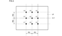
- Three central axis positions arranged at R / 2 pitch on the central axis, and six R / 2 positions arranged at R / 2 positions in the radial direction from each central axis position. When defined as 9 vertical cross-sectional observation positions, The microstructure at each longitudinal section observation position contains ferrite and the rest consists of pearlite and / or bainite.
- the arithmetic mean value of the area fraction of ferrite at the nine vertical cross-sectional observation positions is 50 to 70%, and the standard deviation of the area fraction of the ferrite is 4.0% or less.
- the ratio of the maximum average particle size to the minimum average particle size is 2.00 or less.
- the steel material according to the present disclosure has excellent machinability, has excellent bending fatigue strength and surface fatigue strength after vacuum carburizing treatment, and can suppress heat treatment deformation after vacuum carburizing treatment.
- FIG. 2 is a schematic view for explaining a cross-sectional observation position where microstructure observation is carried out in a cross section perpendicular to the longitudinal direction of the steel material of the present embodiment.
- FIG. 3 is a schematic view for explaining a vertical cross-sectional observation position in which microstructure observation is carried out in a vertical cross section including the central axis, which is parallel to the longitudinal direction of the steel material of the present embodiment.
- FIG. 4 is a schematic diagram of the band structure.
- FIG. 5 is a diagram showing an example of heat patterns in the vacuum carburizing step and the quenching step.
- FIG. 6 is a plan view of the Ono-type rotary bending test piece produced in the example.
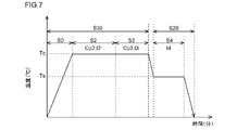
- FIG. 7 is a diagram showing an example of heat patterns in the gas carburizing step and the quenching step.
- FIG. 8 is a plan view of the test piece for the roller pitching fatigue test produced in the example.
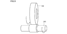
- FIG. 9 is a schematic diagram for explaining a roller pitching fatigue test.
- FIG. 10 is a front view of the large roller test piece produced in the example.
- FIG. 11A is a perspective view of the gear simulated test piece produced in the example.
- 11B is a perspective view of the through hole in FIG. 11A.
- the present inventors have excellent machinability, have excellent bending fatigue strength and surface fatigue strength when subjected to vacuum carburizing treatment to obtain mechanical structural parts, and after vacuum carburizing treatment.
- the present inventors examined a steel material having excellent machinability and further having excellent bending fatigue strength and surface fatigue strength after vacuum carburizing treatment from the viewpoint of chemical composition.
- the chemical composition was C: 0.18 to 0.25%, Si: 0.70 to 2.00%, Mn: 0.70 to 1.50%, S: 0.005 in mass%. ⁇ 0.050%, N: 0.0050 to 0.0200%, Al: 0.001 to 0.100%, O: 0.0050% or less, P: 0.030% or less, Mo: 0 to 0.
- Nb 0 to 0.050%
- Cr 0 to 0.60%
- Ti 0 to 0.020%
- Cu 0 to 0.50%
- Ni 0 to 0.80%
- V A steel material containing 0 to 0.30%
- Mg 0 to 0.0035%
- Ca 0 to 0.0030%
- rare earth elements 0 to 0.0050%, with the balance being Fe and impurities.
- it is considered that it has excellent machinability and may have excellent bending fatigue strength and surface fatigue strength after vacuum carburizing treatment.
- the present inventors further assume that the content of each element in the chemical composition is within the above range, and further satisfy the following formula (1) to have excellent bending fatigue strength after vacuum carburizing treatment. I thought there was a possibility. Si / Mn ⁇ 1.00 (1) Here, the content (mass%) of the corresponding element is substituted for each element symbol in the formula (1).
- the inclusions are soft MnO-SiO 2 .
- the inclusions are vitrified during hot working (hot rolling), stretched and fragmented, and refined. Therefore, coarse inclusions that reduce the bending fatigue strength can be reduced, and the bending fatigue strength is increased.
- the present inventors further investigated means for suppressing heat treatment deformation in vacuum carburizing treatment.
- the present inventors focused on the microstructure of steel materials. If the microstructure at each part of the steel material is as uniform as possible, specifically, if the variation in the phase composition of the microstructure at each part in the steel material and the variation in the crystal grains are suppressed, the vacuum Variations in the timing of martensitic transformation during carburizing and quenching can be suppressed. As a result, heat treatment deformation can be suppressed. Therefore, the present inventors investigated the phase composition and the crystal grain size at each part of the steel material.
- the present inventors first focused on the variation in microstructure in the cross section, which is the cross section perpendicular to the longitudinal direction of the steel material.
- the cross-sectional observation position which is the observation position of the microstructure in the cross section.
- the center position of the cross section and the position of R / 2 in the radial direction from the center of the cross section are arranged at a pitch of 45 ° around the center of the cross section 8
- the R / 2 position of the location is defined as the cross-sectional observation position of 9 locations.
- the present inventors investigated and examined the microstructure at each cross-sectional observation position. As a result of the examination, it was found that the heat treatment deformation after the carburizing treatment is suppressed if the microstructure at the cross-sectional observation position meets the following requirements.
- the microstructure at each cross-sectional observation position contains ferrite, and the balance consists of pearlite and / or bainite.
- the arithmetic mean value of the area fraction of ferrite at nine cross-sectional observation positions is 50 to 70%, and the standard deviation of the area fraction of ferrite is 4.0% or less.
- the ratio of the maximum average particle size to the minimum average particle size is 2.00 or less.
- the present inventors paid attention not only to the variation in the microstructure of the cross section of the steel material but also to the variation of the microstructure of the vertical cross section of the steel material. Then, in order to quantify the variation of the microstructure in the vertical section, the vertical section observation position, which is the observation position of the microstructure in the vertical section, is defined as follows.
- the present inventors investigated and examined the microstructure at each vertical cross-sectional observation position. As a result of the examination, if the microstructure at the cross-sectional observation position meets the above requirements and the microstructure at the vertical cross-section observation position meets the following requirements, the heat treatment deformation after the gas carburizing treatment is sufficiently suppressed. There was found.
- the microstructure at each vertical cross-sectional observation position contains ferrite, and the balance consists of pearlite and / or bainite.
- the arithmetic mean value of the area fraction of ferrite at nine vertical cross-sectional observation positions is 50 to 70%, and the standard deviation of the area fraction of ferrite is 4.0% or less.
- the ratio of the maximum average particle size to the minimum average particle size is 2.00 or less.
- the present inventors focused on martensitic transformation after vacuum carburizing. Then, the present inventors investigated in detail the mechanism of occurrence of martensitic transformation during vacuum carburizing and quenching.
- the present inventors first attempted to suppress heat treatment deformation by using a steel material having the above-mentioned chemical composition and making the martensitic transformation time at each part of the mechanical structural parts as similar as possible. Specifically, it is possible to suppress heat treatment deformation by suppressing variations in the microstructure at each part of the steel material (cross-section observation position, vertical cross-section observation position) and by suppressing variations in the Ms point of each part as much as possible. I tried.
- the microstructural changes of the steel material during the vacuum carburizing treatment occur as follows.
- quenching time quenching time
- martensitic transformation starts in a part of the inside of the steel material first. After that, as time progresses, martensitic transformation progresses from the central part toward the surface layer part. That is, the martensitic transformation occurs not from the surface layer of the steel material but from the inside of the steel material.
- the carbon concentration on the surface layer of the steel material is higher than the carbon concentration inside the steel material. Therefore, the Ms point on the surface layer of the steel material is lower than the Ms point inside the steel material. Further, even if it is possible to make the Ms points uniform in each part inside the steel material, the cooling rates of each part are not completely the same due to the shape of the steel material. Therefore, when the quenching time is divided into minute times, the martensitic transformation starts from each part of the steel material where the cooling rate inside the steel material is high. Therefore, at the time of quenching of the gas carburizing treatment, a minute time zone in which the martensitic transformed portion and the martensitic untransformed portion coexist always occurs.
- the present inventors do not suppress the heat treatment deformation by setting the martensitic transformation time as much as possible, but during the vacuum carburizing treatment, the martensitic transformed portion and the martensitic untransformed portion are mixed.
- the means for suppressing heat treatment deformation was investigated.
- the untransformed part of martensite is softer than the transformed part of martensite.
- the martensitic transformational portion having a body-centered cubic lattice structure has a larger volume than the martensitic untransformed portion having a face-centered cubic lattice structure. Therefore, when a part of the steel material undergoes martensitic transformation during quenching, and the martensitic transformed portion and the martensitic untransformed portion coexist, the martensitic untransformed portion is distorted. It is considered that this strain causes heat treatment deformation.
- the present inventors assume that there is a minute time zone in which the martensitic transformed portion and the martensitic untransformed portion coexist during the vacuum carburizing treatment, and when the martensitic transformed portion is generated, It was considered that if the strength of the untransformed martensite portion could be kept high, the occurrence of distortion in the untransformed martensite portion could be suppressed, and as a result, the heat treatment deformation could be suppressed.
- the present inventors further investigated a means for maintaining high strength of the martensitic untransformed portion when the martensitic transformed portion is generated during quenching in the vacuum carburizing treatment.
- the martensitic untransformed portion is strengthened in the temperature range where the martensitic transformed portion is generated. It is effective to appropriately contain the elements to be used.
- the present inventors considered that C, Si, Mn, Cr and Mo are effective as elements for increasing the strength of the martensitic untransformed portion in the temperature range where the martensitic transformed portion is generated. .. Therefore, the relationship between these elements and the amount of heat treatment deformation during quenching of the gas carburizing treatment was further investigated. As a result, it was found that the heat treatment deformation was remarkably suppressed by further satisfying the following formula (2) in the steel material having the above-mentioned chemical composition.
- 1- 0.5C + 0.03Si + 0.06Mn + 0.01Cr + 0.05Mo
- the content (mass%) of the corresponding element is substituted for each element symbol in the formula (2). If the corresponding element is not contained, "0" is substituted for the element symbol.
- FIG. 1 shows the F2 value and the maximum in a steel material in which the content of each element in the chemical composition is within the above range and the variation in microstructure at the cross-sectional observation position and the vertical cross-sectional observation position satisfies the above-mentioned requirements. It is a figure which shows the relationship with the deformation amount ratio (%).
- the maximum deformation ratio is an index of heat treatment deformation. The larger the maximum deformation amount ratio, the larger the heat treatment deformation of the steel material. The maximum deformation amount ratio was determined by the method described later.
- the content of each element in the chemical composition is within the above range, and the microstructure at the cross-sectional observation position and the vertical cross-sectional observation position satisfies the above-mentioned conditions (1) to (6).
- the maximum deformation amount ratio decreases as F2 decreases.
- F2 is less than 0.800
- the present inventors suppress the variation in the microstructure at the cross-sectional observation position and the vertical section observation position in the steel material having the above-mentioned chemical composition, and suppress the variation in the timing of martensitic transformation during quenching to some extent.
- it has excellent machinability by setting F2 to less than 0.800 on the premise that a minute time zone in which martensite transformed portion and martensite untransformed portion coexist is inevitably generated at the time of quenching. It has been found that it has excellent bending fatigue strength and excellent surface fatigue strength after vacuum carburizing treatment, and can sufficiently suppress heat treatment deformation after vacuum carburizing treatment.
- the steel material according to the present embodiment completed based on the above knowledge has the following constitution.
- the microstructure at each cross-sectional observation position contains ferrite and the rest consists of pearlite and / or bainite.
- the arithmetic mean value of the area fraction of the ferrite at the nine cross-sectional observation positions is 50 to 70%, and the standard deviation of the area fraction of the ferrite is 4.0% or less.
- the ratio of the maximum average grain size to the minimum average grain size is 2.00 or less.
- Three central axis positions arranged at R / 2 pitch on the central axis, and six R / 2 positions arranged at R / 2 positions in the radial direction from each central axis position. When defined as 9 vertical cross-sectional observation positions, The microstructure at each longitudinal section observation position contains ferrite and the rest consists of pearlite and / or bainite.
- the arithmetic mean value of the area fraction of ferrite at the nine vertical cross-sectional observation positions is 50 to 70%, and the standard deviation of the area fraction of the ferrite is 4.0% or less.
- the ratio of the maximum average particle size to the minimum average particle size is 2.00 or less.
- Steel material Si / Mn ⁇ 1.00 (1) 1- (0.5C + 0.03Si + 0.06Mn + 0.01Cr + 0.05Mo) ⁇ 0.800 (2)
- the content (mass%) of the corresponding element is substituted for each element symbol in the formula (1) and the formula (2). If the corresponding element is not contained, "0" is substituted for the element symbol.
- Carbon (C) increases the strength of the steel material. If the C content is less than 0.18%, the above effect cannot be sufficiently obtained even if the content of other elements is within the range of the present embodiment. On the other hand, if the C content exceeds 0.25%, the hardenability becomes excessively high even if the content of other elements is within the range of the present embodiment. In this case, the hardness of the mechanical structural parts after the vacuum carburizing treatment becomes excessively high. As a result, the machinability of mechanical structural parts is significantly reduced. Therefore, the C content is 0.18 to 0.25%.
- the lower limit of the C content is preferably 0.19%, more preferably 0.20%, still more preferably 0.21%.
- the preferred upper limit of the C content is 0.24%, more preferably 0.23%, still more preferably 0.22%.
- Si 0.70 to 2.00%
- Silicon (Si) enhances the hardenability of the steel material and enhances the strength of the steel material. Si further enhances the temper softening resistance of the hardened layer when steel is used as a mechanical structural component. Therefore, the surface fatigue strength of the mechanical structural parts is increased. If the Si content is less than 0.70%, the above effect cannot be sufficiently obtained even if the content of other elements is within the range of the present embodiment. On the other hand, if the Si content exceeds 2.00%, the hardenability is too high even if the content of other elements is within the range of the present embodiment. Therefore, the hardness of the steel material after the vacuum carburizing treatment becomes high. Therefore, the machinability of the steel material is significantly reduced. Therefore, the Si content is 0.70 to 2.00%.
- the lower limit of the Si content is preferably 0.71%, more preferably 0.72%, still more preferably 0.75%.
- the preferred upper limit of the Si content is 1.90%, more preferably 1.70%, still more preferably 1.50%, still more preferably 1.47%, still more preferably 1.45%. %.
- Mn 0.70 to 1.50%
- Manganese (Mn) enhances the hardenability of steel materials and enhances the bending fatigue strength and surface fatigue strength of mechanical structural parts. If the Mn content is less than 0.70%, the above effect cannot be sufficiently obtained even if the content of other elements is within the range of the present embodiment. On the other hand, if the Mn content exceeds 1.50%, the steel material becomes too hard even if the content of other elements is within the range of the present embodiment. In this case, the machinability of the steel material is reduced. Therefore, the Mn content is 0.70 to 1.50%.
- the preferred lower limit of the Mn content is more than 0.70%, more preferably 0.75%, still more preferably 0.80%.
- the preferred upper limit of the Mn content is less than 1.50%, more preferably 1.45%, still more preferably 1.40%, still more preferably 1.35%.
- S 0.005 to 0.050% Sulfur (S) combines with Mn to form MnS.
- MnS enhances the machinability of steel materials. If the S content is less than 0.005%, the above effect cannot be sufficiently obtained even if the content of other elements is within the range of the present embodiment. On the other hand, if the S content exceeds 0.050%, MnS is excessively formed even if the content of other elements is within the range of the present embodiment. In this case, the bending fatigue strength and the surface fatigue strength of the mechanical structural parts are reduced. Therefore, the S content is 0.005 to 0.050%.
- the lower limit of the S content is preferably 0.010%, more preferably 0.013%, still more preferably 0.015%.
- the preferred upper limit of the S content is less than 0.050%, more preferably 0.035%, still more preferably 0.025%.
- N 0.0050-0.0200%
- Nitrogen (N) combines with Al and Nb to form AlN and NbN.
- AlN and NbN suppress the coarsening of crystal grains during heating in the vacuum carburizing treatment due to the pinning effect. If the N content is less than 0.0050%, the above effect cannot be sufficiently obtained even if the content of other elements is within the range of the present embodiment. On the other hand, if the N content exceeds 0.0200%, scratches are likely to occur on the surface of the manufactured slab or ingot in the steelmaking process even if the content of other elements is within the range of the present embodiment. .. Therefore, the N content is 0.0050 to 0.0200%.
- the lower limit of the N content is preferably 0.0100%, more preferably 0.0120%, still more preferably 0.0130%.
- the preferred upper limit of the N content is less than 0.0200%, more preferably 0.0190%, still more preferably 0.0180%, still more preferably 0.0150%.
- Al 0.001 to 0.100%
- Aluminum (Al) deoxidizes steel. Al further combines with N to form AlN. AlN suppresses the coarsening of crystal grains during heating in the vacuum carburizing treatment due to the pinning effect. If the Al content is less than 0.001%, the above effect cannot be sufficiently obtained even if the content of other elements is within the range of the present embodiment. On the other hand, if the Al content exceeds 0.100%, the formation of a coarse Al oxide is promoted even if the content of other elements is within the range of the present embodiment. The coarse Al oxide reduces the bending fatigue strength of mechanical structural parts. Therefore, the Al content is 0.001 to 0.100%.
- the preferred lower limit of the Al content is 0.010%, more preferably 0.020%, still more preferably 0.025%, still more preferably 0.027%, still more preferably 0.030. %.
- the preferred upper limit of the Al content is 0.090%, more preferably 0.070%, still more preferably 0.050%, still more preferably 0.045%, still more preferably 0.040. %, More preferably 0.035%.
- Oxygen (O) is an impurity. O combines with other elements in the steel to form coarse oxide inclusions. Coarse oxide-based inclusions reduce the bending fatigue strength of mechanical structural parts. If the O content exceeds 0.0050%, the bending fatigue strength of the mechanical structural parts is significantly reduced even if the content of other elements is within the range of the present embodiment. Therefore, the O content is 0.0050% or less.
- the preferred upper limit of the O content is 0.0040%, more preferably 0.0030%, still more preferably 0.0020%, still more preferably 0.0015%. It is preferable that the O content is as low as possible. However, excessive reduction of O content raises manufacturing costs. Therefore, when considering normal industrial production, the preferred lower limit of the O content is more than 0%, more preferably 0.0001%, still more preferably 0.0005%, still more preferably 0.0010. %.
- Phosphorus (P) is an impurity. P segregates at the grain boundaries and lowers the grain boundary strength. If the P content exceeds 0.030%, even if the content of other elements is within the range of the present embodiment, P is excessively segregated at the grain boundaries to reduce the grain boundary strength, and as a result, the machine. Bending fatigue strength and surface fatigue strength of structural parts are reduced. Therefore, the P content is 0.030% or less.
- the preferred upper limit of the P content is 0.025%, more preferably 0.020%, still more preferably 0.015%. It is preferable that the P content is as low as possible. However, excessive reduction of P content raises manufacturing costs. Therefore, when considering normal industrial production, the preferred lower limit of the P content is more than 0%, more preferably 0.001%, still more preferably 0.005%, still more preferably 0.010. %.
- the balance of the chemical composition of the steel material according to this embodiment consists of Fe and impurities.
- the impurities are mixed from ore, scrap, or the manufacturing environment as a raw material when the steel material is industrially manufactured, and are within a range that does not adversely affect the steel material of the present embodiment. Means what is acceptable.
- the impurities referred to here are B, Pb, W, Sb, Bi, Co, Ta, Sn, In, Zr, Te, Se, Zn and the like.
- the total content of impurities other than O and P is 0.01% or less. Of the above impurities, the B content is 0.0003% or less.
- the chemical composition of the steel material of the present embodiment is replaced with a part of Fe.
- Mo 0.50% or less
- Nb 0.050% or less
- Cr 0.60% or less
- Ti 0.020% or less
- Cu 0.50% or less
- Ni 0.80% or less
- V 0.30% or less
- Mg 0.0035% or less
- Ca 0.0030% or less
- Rare earth element It may contain one or more elements selected from the group consisting of 0.0050% or less. These elements are arbitrary elements, and all of them enhance the bending fatigue strength and the surface fatigue strength of mechanical structural parts.
- Mo Molybdenum
- Mo Molybdenum
- Mo is an optional element and may not be contained. That is, the Mo content may be 0%.
- Mo enhances the hardenability of steel materials and enhances bending fatigue strength and surface fatigue strength of mechanical structural parts. If Mo is contained even in a small amount, the above effect can be obtained to some extent. However, if the Mo content exceeds 0.50%, the steel material becomes too hard even if the content of other elements is within the range of the present embodiment. In this case, the machinability of the steel material is reduced. Therefore, the Mo content is 0 to 0.50%, and when it is contained, it is 0.50% or less (that is, more than 0 to 0.50%).
- the lower limit of the Mo content is preferably 0.01%, more preferably 0.02%, still more preferably 0.05%, still more preferably 0.10%.
- the preferred upper limit of the Mo content is less than 0.50%, more preferably 0.45%, still more preferably 0.40%, still more preferably 0.35%.
- Niobium (Nb) is an optional element and may not be contained. That is, the Nb content may be 0%.
- Nb binds to C and / or N to form Nb precipitates (NbC, NbN, Nb (CN), etc.). Similar to AlN, the Nb precipitate suppresses the coarsening of crystal grains in the gas carburizing treatment due to the pinning effect. Therefore, the bending fatigue strength and the surface fatigue strength of the mechanical structural parts are increased. If even a small amount of Nb is contained, the above effect can be obtained to some extent.
- the Nb content is 0 to 0.050%, and when it is contained, it is 0.050% or less (that is, more than 0 to 0.050%).
- the preferred lower limit of the Nb content is 0.001%, more preferably 0.010%, still more preferably 0.015%, still more preferably 0.020%, still more preferably 0.025. %.
- the preferred upper limit of the Nb content is less than 0.050%, more preferably 0.045%, still more preferably 0.040%, still more preferably 0.035%.
- Chromium (Cr) is an optional element and may not be contained. That is, the Cr content may be 0%. When contained, Cr enhances the hardenability of steel materials and enhances bending fatigue strength and surface fatigue strength of mechanical structural parts. If even a small amount of Cr is contained, the above effect can be obtained to some extent. However, if the Cr content exceeds 0.60%, excessive carburizing is likely to occur on the surface layer of the mechanical structural parts during the vacuum carburizing treatment even if the other element content is within the range of the present embodiment. In this case, coarse cementite is formed at the grain boundaries. Therefore, the bending fatigue strength of the mechanical structural parts is reduced.
- the Cr content is 0 to 0.60%, and when it is contained, it is 0.60% or less (that is, more than 0 to 0.60%).
- the lower limit of the Cr content is preferably 0.01%, more preferably 0.05%, still more preferably 0.10%.
- the preferred upper limit of the Cr content is less than 0.60%, more preferably 0.55%, still more preferably 0.50%, still more preferably 0.45%, still more preferably 0. It is 40%.
- Titanium (Ti) is an optional element and may not be contained. That is, the Ti content may be 0%. When contained, Ti forms Ti precipitates (TiC, TiN, Ti (CN), etc.) as well as Nb. The Ti precipitate suppresses the coarsening of crystal grains in the gas carburizing treatment due to the pinning effect. Therefore, the bending fatigue strength and the surface fatigue strength of the mechanical structural parts are increased. If even a small amount of Ti is contained, the above effect can be obtained to some extent. However, if the Ti content exceeds 0.020%, the Ti precipitate will be coarsened even if the content of other elements is within the range of this embodiment.
- the Ti content is 0 to 0.020%, and when it is contained, it is 0.020% or less (that is, more than 0 to 0.020%).
- the lower limit of the Ti content is preferably 0.001%, more preferably 0.005%, still more preferably 0.010%.
- the preferred upper limit of the Ti content is 0.019%, more preferably 0.017%, still more preferably 0.015%.
- Cu 0.50% or less Copper (Cu) is an optional element and may not be contained. That is, the Cu content may be 0%. When contained, Cu enhances the hardenability of steel materials and enhances bending fatigue strength and surface fatigue strength of mechanical structural parts. If even a small amount of Cu is contained, the above effect can be obtained to some extent. However, if the Cu content exceeds 0.50%, the steel material becomes too hard even if the content of other elements is within the range of this embodiment. In this case, the machinability of the steel material is reduced. Therefore, the Cu content is 0 to 0.50%, and when it is contained, it is 0.50% or less (that is, more than 0 to 0.50%).
- the lower limit of the Cu content is preferably 0.01%, more preferably 0.05%, still more preferably 0.10%.
- the preferred upper limit of the Cu content is 0.45%, more preferably 0.40%, still more preferably 0.30%, still more preferably 0.25%.
- Nickel (Ni) is an optional element and may not be contained. That is, the Ni content may be 0%. When contained, Ni enhances the hardenability of steel materials and enhances the bending fatigue strength and surface fatigue strength of mechanical structural parts. If even a small amount of Ni is contained, the above effect can be obtained to some extent. However, if the Ni content exceeds 0.80%, the steel material becomes too hard even if the content of other elements is within the range of the present embodiment. In this case, the machinability of the steel material is reduced. Therefore, the Ni content is 0 to 0.80%, and when it is contained, it is 0.80% or less (that is, more than 0 to 0.80%).
- the lower limit of the Ni content is preferably 0.01%, more preferably 0.05%, still more preferably 0.10%.
- the preferred upper limit of the Ni content is 0.70%, more preferably 0.60%, still more preferably 0.40%, still more preferably 0.20%.
- V 0.30% or less Vanadium (V) is an optional element and may not be contained. That is, the V content may be 0%. When contained, V forms V precipitates (VC, VN, V (CN), etc.), similar to Nb. The V precipitate suppresses the coarsening of crystal grains in the gas carburizing treatment due to the pinning effect. Therefore, the bending fatigue strength and the surface fatigue strength of the mechanical structural parts are increased. If V is contained even in a small amount, the above effect can be obtained to some extent. However, if the V content exceeds 0.30%, the steel material becomes too hard even if the content of other elements is within the range of the present embodiment. In this case, the machinability of the steel material is reduced.
- the V content is 0 to 0.30%, and when it is contained, it is 0.30% or less (that is, more than 0 to 0.30%).
- the lower limit of the V content is preferably 0.01%, more preferably 0.03%, still more preferably 0.04%.
- the preferred upper limit of the V content is 0.20%, more preferably 0.15%, still more preferably 0.10%.
- Mg 0.0035% or less
- Magnesium (Mg) is an optional element and may not be contained. That is, the Mg content may be 0%. When contained, Mg deoxidizes steel, similar to Al. In this case, the formation of coarse oxides is suppressed. Therefore, the bending fatigue strength and the surface fatigue strength of the mechanical structural parts are increased. If even a small amount of Mg is contained, the above effect can be obtained to some extent. However, if the Mg content exceeds 0.0035%, the formation of coarse Mg oxides in the steel material is promoted even if the content of other elements is within the range of the present embodiment. In this case, the limit machining rate during hot machining decreases.
- the Mg content is 0 to 0.0035%, and when it is contained, it is 0.0035% or less (that is, more than 0 to 0.0035%).
- the preferable lower limit of the Mg content is 0.0001%, more preferably 0.0003%, still more preferably 0.0005%.
- the preferred upper limit of the Mg content is 0.0030%, more preferably 0.0028%, still more preferably 0.0025%, still more preferably 0.0020%.
- Ca 0.0030% or less Calcium (Ca) is an optional element and may not be contained. That is, the Ca content may be 0%.
- Ca refines sulfides in steel. Ca further promotes spheroidization of sulfides in steel. Therefore, the bending fatigue strength and the surface fatigue strength of the mechanical structural parts are increased. If even a small amount of Ca is contained, the above effect can be obtained to some extent. However, if the Ca content exceeds 0.0030%, coarse Ca oxides are formed in the steel material even if the content of other elements is within the range of this embodiment. In this case, the bending fatigue strength and the surface fatigue strength of the mechanical structural parts are reduced.
- the Ca content is 0 to 0.0030%, and when it is contained, it is 0.0030% or less (that is, more than 0 to 0.0030%).
- the preferred lower limit of the Ca content is 0.0001%, more preferably 0.0002%, still more preferably 0.0005%, still more preferably 0.0007%, still more preferably 0.0010. %.
- the preferred upper limit of the Ca content is 0.0025%, more preferably 0.0022%, still more preferably 0.0020%.
- Rare earth element (REM) 0.0050% or less
- Rare earth element (REM) is an optional element and may not be contained. That is, the REM content may be 0%. When contained, the REM dissolves in the sulfide in the steel material and suppresses the stretching of MnS. As a result, the bending fatigue strength and the surface fatigue strength of the mechanical structural parts are increased. If even a small amount of REM is contained, the above effect can be obtained to some extent. However, if the REM content exceeds 0.0050%, coarse oxides will be produced even if the content of other elements is within the range of this embodiment. In this case, the bending fatigue strength and the surface fatigue strength of the mechanical structural parts are reduced.
- the REM content is 0 to 0.0050%, and when contained, it is 0.0050% or less (that is, more than 0 to 0.0050%).
- the preferred lower limit of the REM content is 0.0001%, more preferably 0.0010%, still more preferably 0.0020%.
- the preferred upper limit of the REM content is 0.0045%, more preferably 0.0040%, still more preferably 0.0035%, still more preferably 0.0030%.
- the REMs are scandium (Sc) having an atomic number of 21, yttrium (Y) having an atomic number of 39, and lanthanum (La) having an atomic number of 57 to lutetium having an atomic number of 71 (Lutetium). It is one or more elements selected from the group consisting of Lu).
- the REM content in the present specification is the total content of these elements.
- MnO-SiO 2 has a melting point of about 1250 ° C. Therefore, it is liquid in the molten metal before solidification, but becomes solid in the steel pieces after solidification, and becomes vitrified soft inclusions.
- the bending fatigue strength of the mechanical structural parts manufactured from the steel material of the present embodiment increases.
- the bending fatigue strength is higher than that of SCM420H specified in JIS G4052 (2016). Therefore, when F1 satisfies the formula (1), that is, when F1 is 1.00 or more, it is assumed that the content of each element is within the range of the present embodiment and F2 satisfies the formula (2).
- the bending fatigue strength of the mechanical structural parts manufactured using the steel material of the present embodiment is sufficiently increased.
- the preferred lower limit of F1 is 1.05, more preferably 1.07, and even more preferably 1.10.
- the upper limit of F1 is not particularly limited. However, considering the content of each element in the chemical composition of the present embodiment, the preferred upper limit of F1 is 2.10, more preferably 2.00, and even more preferably 1.70.
- the microstructure of the steel material of the present embodiment contains ferrite, the balance is pearlite and / or bainite, and the surface integral of ferrite is 50 to 70%.
- the surface integral of ferrite is less than 50%, the surface integral of pearlite and / or bainite is too high in the steel material. In this case, the hardness of the steel material is excessively increased. As a result, the machinability of the steel material is reduced. On the other hand, if the surface integral of the ferrite exceeds 70%, the crystal grain size tends to vary during the gas carburizing treatment. Therefore, heat treatment deformation occurs excessively during the gas carburizing treatment.
- the surface integral of ferrite is 50 to 70% and the balance other than ferrite in the microstructure is pearlite and / or bainite, the machinability of the steel material is sufficiently enhanced. Further, heat treatment deformation during gas carburizing treatment can be suppressed.
- the microstructure at each cross-sectional observation position and each vertical cross-sectional observation position contains 50 to 70% ferrite in area fraction, and the balance is composed of pearlite and / or bainite.
- the preferable lower limit of the surface integral of ferrite at each observation position is 52%, more preferably 55%, still more preferably 57%.
- the preferred upper limit of the surface integral of ferrite at each observation position is 68%, more preferably 65%, still more preferably 63%.
- FIG. 2 is a schematic cross-sectional view of the steel material of the present embodiment, which is a cross section perpendicular to the longitudinal direction.
- the cross-sectional CS of the steel material has a circular shape with a radius R.
- the center position C1 of the cross-section CS and the position of R / 2 in the radial direction from the center position C1 of the cross-section CS are arranged around the center of the cross-section CS at a pitch of 45 °.
- the R / 2 positions C2 to C9 at the locations are defined as the "cross-sectional observation positions" C1 to C9 at the nine locations.
- the microstructure at the cross-sectional observation positions C1 to C9 satisfies the following (A) and (B).
- A) The arithmetic mean value of the area fraction of ferrite at the cross-sectional observation positions C1 to C9 is 50 to 70%, and the standard deviation of the area fraction of ferrite is 4.0% or less.
- the arithmetic mean value of the area fraction of ferrite at the cross-sectional observation positions C1 to C9 is 50 to 70%, and the standard deviation of the area fraction of ferrite. Is 4.0% or less.
- the standard deviation of the ferrite area fraction is 4.0% or less, the variation in the phase fraction of the microstructure at each cross-sectional observation position C1 to C9 is sufficiently suppressed. Therefore, it is possible to suppress variations in the occurrence timing of martensitic transformation at each cross-sectional observation positions C1 to C9 during the gas carburizing treatment.
- the standard deviation of the surface integral of ferrite at the cross-sectional observation positions C1 to C9 exceeds 4.0%, the phase fraction varies greatly at each of the cross-sectional observation positions C1 to C9. In this case, the heat treatment deformation during the gas carburizing treatment cannot be sufficiently suppressed. Therefore, the standard deviation of the surface integral of ferrite at the cross-sectional observation positions C1 to C9 is 4.0% or less.
- the preferred upper limit of the standard deviation of the surface integral of ferrite is 3.8%, more preferably 3.5%, still more preferably 3.0%.
- the lower limit of the standard deviation of the surface integral of ferrite is not particularly limited.
- the preferred lower limit of the standard deviation of the surface integral of ferrite is 0.1%, more preferably 0.5%, still more preferably 1.0%, still more preferably 1.5%.
- ferrite average grain size ratio (maximum value of ferrite average particle size in C1 to C9) / (minimum value of ferrite average particle size in C1 to C9)
- the ferrite average particle size ratio at the cross-sectional observation positions C1 to C9 is 2.00 or less.
- the variation in the average particle size of the ferrite at each of the cross-sectional observation positions C1 to C9 is sufficiently suppressed. That is, the ferrite grains at each position are aligned. Therefore, it is possible to sufficiently suppress the variation in the occurrence of martensitic transformation during the carburizing treatment. Therefore, it is possible to suppress heat treatment deformation of the steel material during the carburizing treatment.
- the ferrite average particle size ratio exceeds 2.00, the ferrite grains at each cross-sectional observation position C1 to C9 are scattered. In this case, the heat treatment deformation of the steel material during the gas carburizing treatment cannot be sufficiently suppressed. Therefore, the ferrite average particle size ratio is 2.00 or less.
- the preferred upper limit of the ferrite average particle size ratio is 1.95, more preferably 1.90, and even more preferably 1.80.
- the lower limit of the ferrite average particle size ratio is not particularly limited.
- the preferred lower limit of the ferrite average particle size ratio is 1.10, more preferably 1.20, still more preferably 1.30, and even more preferably 1.40.
- the variation in microstructure is sufficiently suppressed not only in the above-mentioned cross section but also in the vertical cross section which is parallel to the longitudinal direction of the steel material and includes the central axis of the steel material. ..
- the variation in the microstructure not only in the cross section but also in the vertical section is sufficiently suppressed, so that the heat treatment deformation generated three-dimensionally can be sufficiently suppressed.
- the suppression of the variation in the microstructure in the vertical cross section will be described.
- FIG. 3 is a schematic view of a vertical cross section that is parallel to the longitudinal direction of the steel material of the present embodiment and is a cross section including the central axis.
- the six R / 2 positions L4 to L9 arranged at the / 2 position are defined as the nine “longitudinal section observation positions” L1 to L9.
- the microstructures at the above-mentioned nine vertical cross-sectional observation positions L1 to L9 satisfy the following (C) and (D).
- C The arithmetic mean value of the area fraction of ferrite at the vertical cross-sectional observation positions L1 to L9 is 50 to 70%, and the standard deviation of the area fraction of ferrite is 4.0% or less.
- D Among the average particle diameters of ferrites at the vertical cross-sectional observation positions L1 to L9, the ratio of the maximum average particle size to the minimum average particle size (ferrite average particle size ratio) is 2.00 or less.
- (C) and (D) will be described in detail.
- the arithmetic mean value of the area fraction of ferrite at the vertical cross-sectional observation positions L1 to L9 is 50 to 70%, and the standard deviation of the area fraction of ferrite. Is 4.0% or less.
- the standard deviation of the surface integral of ferrite at the vertical cross-sectional observation positions L1 to L9 is 4.0% or less.
- the preferred upper limit of the standard deviation of the surface integral of ferrite is 3.8%, more preferably 3.5%, still more preferably 3.0%.
- the lower limit of the standard deviation of the surface integral of ferrite is not particularly limited.
- the preferred lower limit of the standard deviation of the surface integral of ferrite is 0.1%, more preferably 0.5%, still more preferably 1.0%, still more preferably 1.5%.
- ferrite average grain size ratio (maximum value of ferrite average particle size in L1 to L9) / (minimum value of ferrite average particle size in L1 to L9)
- the ferrite average particle size ratio at the vertical cross-sectional observation positions L1 to L9 is 2.00 or less.
- the variation in the average particle size of the ferrite at each of the vertical cross-sectional observation positions L1 to L9 is sufficiently suppressed. That is, the ferrite grains at each position are aligned. Therefore, it is possible to sufficiently suppress the variation in the occurrence of martensitic transformation during the carburizing treatment. Therefore, it is possible to suppress heat treatment deformation of the steel material during the carburizing treatment.
- the ferrite average particle size ratio exceeds 2.00, the ferrite grains at each vertical cross-sectional observation position L1 to L9 are scattered. In this case, the heat treatment deformation of the steel material during the gas carburizing treatment cannot be sufficiently suppressed. Therefore, the ferrite average particle size ratio at the nine vertical cross-sectional observation positions L1 to L9 is 2.00 or less.
- the preferred upper limit of the ferrite average particle size ratio is 1.95, more preferably 1.90, and even more preferably 1.80.
- the lower limit of the ferrite average particle size ratio is not particularly limited.
- the preferred lower limit of the ferrite average particle size ratio is 1.10, more preferably 1.20, still more preferably 1.30, and even more preferably 1.40.
- Method of observing microstructure at each observation position Method of measuring surface integral of ferrite and average grain size ratio of ferrite
- the method for observing the microstructure at the cross-sectional observation positions C1 to C9 and the vertical cross-sectional observation positions L1 to L9 of the steel material of the present embodiment, and the method for measuring the area fraction of ferrite and the average grain size ratio of ferrite are as follows. be.
- the method of observing the microstructure of the cross-sectional CS is as follows. A sample including each cross-sectional observation position C1 to C9 is collected from the steel material. Of the surfaces of the sample, the surface corresponding to the cross section CS is used as the observation surface. On the observation surface, the observation field of view including the cross-sectional observation position is 0.5 mm ⁇ 1.0 mm.
- the contrast of each phase such as ferrite, pearlite, and bainite is different for each phase.
- ferrite is observed to be white, and bainite and pearlite are observed to be blacker than ferrite. Therefore, ferrite can be easily distinguished from other phases (pearlite and bainite). Identify ferrite based on contrast.
- the arithmetic mean value of the ferrite area fraction (%) at the nine observation fields (cross-section observation positions) is the arithmetic mean value (%) of the ferrite area fraction at the nine cross-section observation positions C1 to C9. Define.
- the standard deviation (%) of the ferrite area fractions at the nine cross-sectional observation positions C1 to C9 is calculated from the ferrite area fractions (%) at the nine observation fields (cross-section observation positions).
- the standard deviation here is the sample standard deviation.
- the average particle size of the ferrites at the cross-sectional observation positions C1 to C9 at 9 locations are obtained. Then, among the average particle diameters of these ferrites, the maximum average particle diameter ( ⁇ m) and the minimum average particle diameter ( ⁇ m) of the ferrites are specified. The ratio of the maximum average particle size to the specified minimum average particle size (ferrite average particle size ratio) is obtained.
- the method of observing the microstructure of the vertical cross section LS is as follows. A sample including each vertical cross-sectional observation position L1 to L9 is taken from the steel material. Of the surface of the sample, the surface corresponding to the vertical cross section LS is used as the observation surface. On the observation surface, the observation field of view including the vertical cross-sectional observation position is 0.5 mm ⁇ 1.0 mm. More specifically, the length of 0.5 mm of the observation field of view is defined as the radial direction of the steel material, and 1.0 mm is defined as the longitudinal direction of the steel material.
- the observation field of view (0.5 mm ⁇ 1.0 mm) of the etched observation surface is observed with a 100x optical microscope.
- Each phase in the observation field is identified by the same method as the microstructure observation of the cross-sectional CS.
- the arithmetic mean value of the ferrite area fraction (%) in the nine observation fields (vertical cross-section observation positions) is the arithmetic mean value (%) of the ferrite area fraction in the nine vertical cross-section observation positions L1 to L9. Define.
- the standard deviation (%) of the ferrite area fractions at the nine vertical cross-sectional observation positions L1 to L9 is calculated from the ferrite area fractions (%) at the nine observation fields (vertical cross-sectional observation positions).
- the steel material of the present embodiment not only the cross-sectional CS but also the microstructure of the vertical cross-sectional LS is made uniform.
- the microstructures of the cross-sectional observation positions C1 to C9 in the cross-section CS satisfy (A) and (B)
- the microstructures of the vertical cross-section observation positions L1 to L9 in the vertical cross-section LS satisfy (C) and.
- (D) even if the microstructure is made uniform, as described above, a minute time zone in which the martensitic transformed portion and the martensitic untransformed portion coexist always occurs at the time of quenching of the vacuum carburizing treatment. If the amount of heat treatment strain in the martensite untransformed portion is large in this minute time zone, heat treatment deformation will occur. Therefore, the steel material of the present embodiment further satisfies the formula (2).
- F2 1- (0.5C + 0.03Si + 0.06Mn + 0.01Cr + 0.05Mo).
- F2 is an index relating to the amount of heat treatment deformation of the steel material in the gas carburizing treatment with respect to the steel material.
- C, Si, Mn, Cr and Mo contained in F2 are particularly martensite in a minute time zone in which a martensitic transformed portion and a martensitic untransformed portion are mixed at the time of quenching. Increases the strength of untransformed parts.
- the maximum deformation amount ratio decreases, and the heat treatment deformation amount decreases.
- the preferred upper limit of F2 is 0.799, more preferably 0.797, and even more preferably 0.795.
- the lower limit of F2 is not particularly limited. However, considering the upper limit of the content of each element in the chemical composition of the present embodiment, the preferable lower limit of F2 is 0.765, more preferably 0.770, and even more preferably 0.775.
- the numerical value of F2 is a value obtained by rounding off to the fourth decimal place.
- the steel material of the present embodiment having the above structure has a cross section in which the content of each element in the chemical composition is within the range of the present embodiment, and F1 and F2 satisfy the formulas (1) and (2).
- the microstructures at the observation positions C1 to C9 and the vertical cross-sectional observation positions L1 to L9 are within the scope of the present embodiment. Therefore, the machinability after hot working on the steel material of the present embodiment is excellent. Further, when the steel material of the present embodiment is subjected to the vacuum carburizing treatment, the mechanical structural parts have excellent bending fatigue strength and surface fatigue strength, and can sufficiently suppress heat treatment deformation.
- the steel material of the present embodiment is a so-called as-rolled material (azurol material). Therefore, in the steel material of the present embodiment, a so-called band structure is observed in the above observation fields of the vertical cross-sectional observation positions L1 to L9.
- the band structure is a well-known microstructure, and as shown in FIG. 4, a ferrite (ferrite band) F extending in the longitudinal direction of the steel material and a non-ferrite (non-ferrite band) NF extending in the longitudinal direction of the steel material are used. However, it means a structure that is alternately laminated in the radial direction. Non-ferrites are pearlite and / or bainite.
- the steel material of the present embodiment is suitable as a material for mechanical structural parts.
- the steel material of the present embodiment is particularly suitable for applications such as gears or shafts of automobile applications, construction machinery, industrial machinery and the like.
- An example of the method for producing a steel material of the present embodiment includes the following steps.
- Process of preparing materials (Material preparation process)
- Process 2 A process of hot-working a material to manufacture a steel material (hot-working process)
- each step will be described.
- the steel material of the present embodiment is prepared. Specifically, a molten steel in which the content of each element in the chemical composition is within the range of the present embodiment, F1 satisfies the formula (1), and F2 satisfies the formula (2) is produced.
- the refining method is not particularly limited, and a well-known method may be used. For example, refining in a converter (primary refining) is performed on hot metal produced by a well-known method. Well-known secondary refining will be carried out on the molten steel discharged from the converter.
- the content of the alloying elements in the molten steel is adjusted so that the content of each element is within the range of the present embodiment, F1 satisfies the formula (1), and F2 satisfies the formula (2).
- the material is manufactured by a well-known casting method.
- an ingot may be manufactured by an ingot method using molten steel.
- bloom or billet may be produced by a continuous casting method using molten steel.
- the material (ingot, bloom or billet) is manufactured by the above method.
- reduction may be applied to the slab in the middle of solidification.
- Step 2 Hot working process the material (ingot, bloom or billet) prepared in the material preparing step is hot-worked to produce the steel material of the present embodiment.
- the shape of the steel material is not particularly limited, but is, for example, steel bar or wire rod. In the following description, a case where the steel material is steel bar will be described as an example. However, even if the steel material has a shape other than that of steel bar, it can be manufactured by the same hot working process.
- the hot working process includes the following steps.
- Step 21 Ingot rolling step Heating temperature: 1250 to 1300 ° C Holding time: 10 hours or more
- Process 22 Finish rolling process Heating temperature: 1150 to 1200 ° C Holding time: 1.5 to 3.0 hours Finishing temperature: 950 to 1000 ° C
- Step 23 Temperature holding step Average cooling rate at 900 to 800 ° C .: 0.05 ° C / sec or less
- Step 24 Cooling step Average cooling rate at 800 to 300 ° C: 0.10 to 1.00 ° C / sec
- each step will be described.
- the material is hot-rolled to produce billets.
- the material is hot-rolled (bulk-rolled) by a lump-rolling machine to manufacture billets.
- a continuous rolling mill is located downstream of the lump rolling mill, hot rolling is further performed on the billet after lump rolling using the continuous rolling mill to produce a smaller billet.
- horizontal stands having a pair of horizontal rolls and vertical stands having a pair of vertical rolls are alternately arranged in a row.
- the slab rolling process the material is produced in billets using a slab rolling mill or using a shunt rolling mill and a continuous rolling mill.
- the conditions in the lump rolling process are as follows. Heating temperature: 1250 to 1300 ° C Holding time: 10 hours or more The heating temperature in the heating furnace in the lump rolling process is 1250 to 1300 ° C. The holding time at the heating temperature (1250-1300 ° C.) is 10 hours or more. If the heating temperature in the heating furnace in the lump rolling process is 1250-1300 ° C. and the holding time at the heating temperature (1250-1300 ° C.) is 10 hours or more, other production conditions must be satisfied. As a premise, the solidification segregation in the material generated during the material preparation process can be sufficiently alleviated.
- the standard deviation of the surface integral of the ferrite at each of the cross-sectional observation positions C1 to C9 and each of the vertical section observation positions L1 to L9 is 4.0% or less.
- the upper limit of the holding time at the heating temperature is not particularly limited. However, considering the manufacturing cost, the preferable upper limit of the holding time at the heating temperature is 30 hours.
- the billet manufactured by the lump-rolling process is allowed to cool (air-cooled) to room temperature before the finish rolling process.
- the surface reduction rate in the ingot rolling process is 30% or more.
- the reduction rate (%) is defined by the following equation.
- Surface reduction rate (%) (1-Area of cross section (cross section perpendicular to longitudinal direction) of steel material after lump rolling / Area of cross section (cross section perpendicular to longitudinal direction) of material before lump rolling) ⁇ 100
- the surface reduction rate in the ingot rolling process is 30% or more, the area of ferrite at each cross-section observation position C1 to C9 and each longitudinal cross-section observation position L1 to L9, assuming that other manufacturing conditions are satisfied.
- the standard deviation of the fraction is 4.0% or less.
- the conditions in the finish rolling process are as follows. Heating temperature: 1150-1200 ° C Holding time: 1.5 to 3.0 hours Finishing temperature: 950 to 1000 ° C
- the heating temperature in the heating furnace in the finish rolling step is 1150 to 1200 ° C.
- the holding time at the heating temperature (1150 to 1200 ° C.) is 1.5 to 3.0 hours. If the heating temperature of the heating furnace in the finish rolling process is 1150 to 1200 ° C. and the holding time at the heating temperature (1150-1200 ° C.) is 1.5 to 3.0 hours, other manufacturing conditions are satisfied. Assuming that, the temperature variation in the steel material (steel bar) can be sufficiently suppressed. Therefore, the ferrite average particle size ratio at the cross-sectional observation positions C1 to C9 and the vertical cross-sectional observation positions L1 to L9 is 2.00 or less.
- finish rolling In the finish rolling process, hot rolling (finish rolling) is carried out by a continuous rolling machine equipped with a plurality of rolling stands arranged in a row. In hot rolling using a continuous rolling mill, the temperature of the steel material on the outlet side of the stand where the steel material is finally rolled is defined as the finishing temperature (° C.).
- the steel material temperature means the surface temperature of the steel material.
- the finishing temperature is 950 to 1000 ° C.
- the finishing temperature is 950 to 1000 ° C.
- the variation in the austenite particle size in the steel material (steel bar) is sufficiently suppressed on the premise that other production conditions are satisfied. Therefore, when the austenite is transformed into ferrite in the temperature holding step and the cooling step described later, the variation in the average particle size of ferrite is sufficiently suppressed. Therefore, the ferrite average particle size ratio at the cross-sectional observation positions C1 to C9 and the vertical cross-sectional observation positions L1 to L9 is 2.00 or less.
- Step 23 Temperature holding step
- the temperature of the steel material is held after the finish rolling step and before the cooling step.
- the conditions in the temperature holding process are as follows. Average cooling rate when the steel material temperature is 900 to 800 ° C: 0.05 ° C / sec or less
- the average cooling rate when the steel material temperature is 900 to 800 ° C is suppressed to 0.05 ° C / sec or less.
- the average cooling rate of the steel material having a steel material temperature of 900 to 800 ° C. is 0.05 ° C./sec using a slow cooling cover, a heat retaining cover, or a temperature holding furnace. Keep it below.
- the average cooling rate at a steel material temperature of 900 to 800 ° C. is 0.05 ° C./sec or less, temperature variation in the axial direction (longitudinal direction) of the steel material can be suppressed on the premise that other manufacturing conditions are satisfied. Therefore, it is possible to suppress variations in the ferrite transformation timing in the axial direction of the steel material. Therefore, in particular, it is possible to suppress the growth variation of the ferrite grains in the axial direction (longitudinal section) of the steel material. Specifically, the following mechanism works.
- austenite gradually transforms into ferrite as the steel material temperature decreases. If the temperature of the steel material varies in the axial direction in the range of 900 to 800 ° C., ferrite produced at a relatively early stage after the finish rolling process and ferrite produced at a relatively late stage coexist. It ends up. In this case, the ferrite grains produced at an early stage tend to be coarser than the ferrite grains transformed at a later stage. As a result, in particular, the variation of ferrite grains becomes large in the axial direction (longitudinal section) of the steel material.
- the average cooling rate at a steel material temperature of 900 to 800 ° C. is high, the temperature variation in the axial direction (longitudinal section) of the steel material becomes large. Therefore, the ferrite average particle size ratio at the vertical cross-sectional observation positions L1 to L9 becomes large.
- the average cooling rate when the steel material temperature is 900 to 800 ° C. is suppressed to 0.05 ° C./sec or less.
- temperature variation in the axial direction (longitudinal cross section) of the steel material can be suppressed. Therefore, the deviation of the ferrite formation (transformation) timing in the vertical cross section of the steel material is suppressed.
- the ferrite average particle size ratio at the vertical cross-sectional observation positions L1 to L9 can be set to 2.00 or less, provided that other manufacturing conditions are satisfied.
- Step 24 Cooling step
- the conditions in the cooling process are as follows. Average cooling rate at a steel temperature of 800 to 300 ° C: 0.10 to 1.00 ° C / sec An average cooling rate of 0.10 to 1.00 ° C / sec for a steel with a steel temperature of 800 to 300 ° C. Cool with. Assuming that the average cooling rate at a steel material temperature of 800 to 300 ° C. is 0.10 to 1.00 ° C./sec, the cross-sectional observation positions C1 to C9 and the vertical cross-sectional observation positions are assumed to satisfy other manufacturing conditions.
- the arithmetic mean value of the area fraction of the ferrite in L1 to L9 is 50 to 70%.
- the steel material of the present embodiment having the above-mentioned configuration can be manufactured.
- the steel material of the present embodiment is a rolled material.
- the steel material of this embodiment is suitable as a material for mechanical structural parts manufactured by performing vacuum carburizing treatment.
- the steel material of the present embodiment may be manufactured as a mechanical structural part by subjecting a surface hardening heat treatment other than the vacuum carburizing treatment.
- Other surface hardening heat treatments include, for example, quenching and tempering, induction hardening and tempering, and soaking treatment (quenching quenching and tempering).
- Mechanical structural parts are used, for example, in automobiles, construction vehicles, and the like. Mechanical structural parts are, for example, gears and shafts used in steering mechanisms.
- the mechanical structural parts made of the steel material of this embodiment are manufactured by a well-known manufacturing method.
- mechanical structural parts are manufactured by the following method.
- An example of a method for manufacturing mechanical structural parts includes the following steps. -Hot working process-Cutting process-Heat treatment process Each process will be described below.
- Hot working process hot working is performed on the steel material of the present embodiment.
- Hot working is, for example, well-known hot forging.
- the heating temperature in the hot working step is, for example, 1000 to 1300 ° C.
- the steel material after hot working is allowed to cool (air cooling). If necessary, the steel material after allowing to cool may be annealed.
- a cutting process is performed on the steel material after the hot working process to manufacture an intermediate product having a predetermined shape. During this cutting process, high machinability of steel materials is required. In the cutting process, well-known cutting is performed. By cutting, it is possible to manufacture precision-shaped machine structural parts, which is difficult only with the hot working process.
- Heat treatment is performed on the intermediate product after cutting.
- the "heat treatment” includes a well-known vacuum carburizing treatment and a well-known tempering step.
- the vacuum carburizing treatment also includes the vacuum carburizing nitriding treatment.
- the vacuum carburizing process includes a vacuum carburizing step and a quenching step. It is a well-known technical matter to those skilled in the art that in the vacuum carburizing treatment, well-known conditions can be appropriately adjusted to appropriately adjust the surface hardness, core hardness, and surface carbon concentration of mechanical structural parts. Hereinafter, a well-known vacuum carburizing process will be described as an example of the heat treatment step. It is well known to those skilled in the art that the well-known vacuum carburizing nitriding treatment is also carried out in the same process as the vacuum carburizing treatment.
- the vacuum carburizing and quenching process includes a vacuum carburizing step and a quenching step.
- the vacuum carburizing process and the quenching process will be described.
- FIG. 5 is a diagram showing an example of a heat pattern in the vacuum carburizing step S10 and the quenching step S20.
- the vertical axis of FIG. 5 is the treatment temperature (° C.) during the vacuum carburizing treatment, and the horizontal axis is the time (minutes).
- the vacuum carburizing step S10 includes a heating step S0, a soaking step S1, a carburizing step S2, and a diffusion step S3.
- the intermediate product charged in the furnace is heated to the carburizing temperature Tc.
- the pressure in the furnace is set to 10 Pa or less.
- the carburizing temperature Tc in the heating step S0 is, for example, 900 to 1100 ° C.
- the intermediate product is held for a predetermined time (holding time t1) at the carburizing temperature Tc, and the soaking heat treatment is carried out.
- the holding time t1 at the carburizing temperature Tc in the soaking step S1 is, for example, 5 to 120 minutes.
- the pressure in the furnace in the soaking step S1 may be 10 Pa or less, or the nitrogen gas may be introduced and evacuated by a vacuum pump at the same time to create a nitrogen gas atmosphere of 1000 Pa or less.
- the intermediate product is held for a predetermined time (holding time t2) at the carburizing temperature Tc.
- the holding time t2 at the carburizing temperature Tc in the carburizing step S2 may be appropriately adjusted.
- the holding time t2 at the carburizing temperature Tc is, for example, 20 to 60 minutes.
- the carburizing gas in the carburizing step S2 a well-known carburizing gas is used.
- the carburized gas is, for example, a hydrocarbon gas such as acetylene, propane or ethylene.
- the carburized gas pressure in the carburizing step S2 is set to a predetermined gas pressure according to the type of carburized gas.
- the carburizing gas pressure is, for example, 10 to 1000 Pa.
- the carburized gas is propane, for example, 200 to 3000 Pa.
- the intermediate product is held for a predetermined time (holding time t3) at the carburizing temperature Tc.
- the holding time t3 at the carburizing temperature Tc in the diffusion step S3 is appropriately adjusted.
- the holding time t3 at the carburizing temperature Tc is, for example, 40 to 90 minutes.
- the pressure in the furnace in the diffusion step S3 may be 100 Pa or less in order to remove the residual gas in the carburizing step.
- the introduction of nitrogen gas and the vacuum exhaust by a vacuum pump may be performed at the same time to create a nitrogen gas atmosphere of 1000 Pa or less.
- the quenching step S20 is carried out on the intermediate product after the vacuum carburizing step S10.
- a well-known cooling method may be used as a cooling method up to the quenching temperature Ts in the quenching step S20 after the vacuum carburizing step S10.
- the cooling method may be, for example, air cooling under vacuum, gas cooling, or any other method.
- cooling is performed at a pressure of 100 Pa or less.
- an inactivated gas such as nitrogen gas and / or helium gas may be used as the cooling gas.
- the quenching step S20 includes a heat soaking step S4.
- the intermediate product after the vacuum carburizing step S10 is held at the quenching temperature.
- the intermediate product is rapidly cooled and quenched.
- the quenching temperature Ts is not particularly limited, but is, for example, 800 to 880 ° C.
- the holding time t4 at the quenching temperature Ts is not particularly limited, but is, for example, 10 to 80 minutes.
- the atmosphere during holding at the quenching temperature Ts is not particularly limited, but is, for example, a nitrogen gas atmosphere.
- the pressure in the furnace may be atmospheric pressure or less, for example, 400 hPa or less.
- the cooling method in the quenching treatment is oil cooling or water cooling. Specifically, an intermediate product maintained at a quenching temperature is immersed in a cooling bath containing oil or water as a cooling medium and rapidly cooled.
- the temperature of the oil or water that is the cooling medium is, for example, 60 to 200 ° C. Further, if necessary, sub-zero processing may be carried out.
- tempering process A well-known tempering process is carried out for intermediate products after the quenching process.
- the tempering temperature is, for example, 100 to 200 ° C.
- the holding time at the tempering temperature is, for example, 90 to 150 minutes.
- the intermediate product after the tempering step may be further subjected to a grinding process or a shot peening process.
- grinding is performed, cutting is performed to give the steel material a shape. By cutting, a more precise shape can be given to the steel material.
- the shot peening treatment is carried out, the compressive residual stress is introduced into the surface layer portion of the intermediate product after the vacuum carburizing treatment. Compressive residual stress suppresses the generation and growth of fatigue cracks. Therefore, the bending fatigue strength and the surface fatigue strength of the mechanical structural parts are increased.
- the shot peening process may be carried out by a well-known method. For example, it is desirable that the shot peening treatment is performed using shot grains having a diameter of 0.7 mm or less and having an arc height of 0.4 mm or more.
- a steel material having the chemical composition shown in Table 1 was prepared.
- the steel type number A corresponds to SCM420H specified in JIS G4052 (2016).
- the steel grade number A in Table 1 means that the measured Nb content was 0% when rounded to the fourth decimal place.
- rounding means that if the digit (fraction) below the specified minimum digit is less than 5, it is rounded down, and if it is 5 or more, it is rounded up.
- the temperature described in the “heating temperature (° C.)” column of the “bulk rolling process” and the “finish rolling process” column is the heating temperature (° C.).
- the time described in the “holding time (time)” column of the “lump rolling process” and the “finish rolling process” column is the holding time (hour) at the heating temperature.
- the temperature in the “Finishing temperature (° C)” column in the “Finish rolling process” column is the steel material temperature (surface temperature of the steel material) (° C) on the outlet side of the last rolled stand in the continuous rolling mill in the finish rolling process. Is.
- the speed described in the "cooling rate (° C./sec)" column of the “temperature holding step” column is the average cooling rate (° C./sec) when the steel material temperature is 900 to 800 ° C.
- the speed described in the "cooling rate (° C./sec)” column of the “cooling step” column is the average cooling rate (° C./sec) when the steel material temperature is 800 to 300 ° C.
- the produced bloom was heated at the heating temperature and holding time shown in Table 2. Then, bloom was lump-rolled using a lump-rolling machine to produce billets.
- the manufactured billet was water-cooled to room temperature (25 ° C.).
- the cross section perpendicular to the longitudinal direction of the billet was a rectangle of 162 mm ⁇ 162 mm.
- the heating temperature and holding time in the lump rolling process are as shown in Table 2.
- the surface reduction rate in the bulk rolling process was 30% or more under all manufacturing conditions.
- the billet after the ingot rolling process was subjected to a finishing rolling process under the conditions shown in Table 2 to produce a steel material (steel bar) having a diameter of 50 mm.
- the billet was heated at the heating temperature (° C.) and holding time (hours) shown in the finish rolling process column of Table 2.
- Finish rolling was carried out on the billets after heating to produce steel bars. At this time, the finishing temperature (° C.) was as shown in Table 2.
- a temperature holding process was carried out on the steel material (steel bar) after the finish rolling process.
- the production conditions a to i were adjusted so that the average cooling rate was 0.05 ° C./sec or less by using a slow cooling cover for the steel material having a steel material temperature of 900 to 800 ° C.
- the steel material having a steel material temperature of 900 to 800 ° C. was allowed to cool without using a slow cooling cover. Therefore, the average cooling rate at a steel material temperature of 900 to 800 ° C. was over 0.05 ° C./sec.
- the cooling process was carried out. Specifically, under each manufacturing condition, the average cooling rate (° C./sec) when the steel material temperature was 800 to 300 ° C. was as shown in the cooling process column of Table 2.
- Test No. 1 is an example using SCM420H, which is a reference steel, and uses manufacturing condition a, which is one of the manufacturing methods generally used for steel materials having a chemical composition of SCM420H.
- the observation surface of the sample was etched with 3% alcohol nitrate (Nital corrosive liquid).
- the observation field of view (0.5 mm ⁇ 1.0 mm) of the etched observation surface was observed with a 100x optical microscope. In the observation field, the phase was identified by contrast.
- the arithmetic mean value of the ferrite area fraction (%) at the nine observation fields (cross-section observation positions) is the arithmetic mean value (%) of the ferrite area fraction at the nine cross-section observation positions C1 to C9. Defined.
- the arithmetic mean value of the obtained ferrite surface integral is shown in the "ferrite surface integral (%)" column of the "cross section” column of Table 3.
- the average particle size of the ferrites at the cross-sectional observation positions C1 to C9 at 9 locations was determined. Then, among the average particle diameters of these ferrites, the maximum average particle diameter ( ⁇ m) and the minimum average particle diameter ( ⁇ m) of ferrite were specified. The ratio of the maximum average particle size to the specified minimum average particle size (ferrite average particle size ratio) was determined. The obtained ferrite average particle size ratio is shown in the "ferrite particle size ratio" column of the "cross section" column of Table 3.
- the observation surface of the sample was etched with 3% alcohol nitrate (Nital corrosive liquid).
- the observation field of view (0.5 mm ⁇ 1.0 mm) of the etched observation surface was observed with a 100x optical microscope. In the observation field, the phase was identified by contrast.
- the observed phase is shown in the "Phase” column of the "Vertical section” column of Table 3.
- the microstructure at all the vertical section observation positions contains ferrite and the balance consists of pearlite and / or bainite, " ⁇ " is indicated.
- the microstructure of the longitudinal section contained ferrite and the balance was pearlite and / or bainite.
- the arithmetic mean value of the ferrite area fraction (%) in the nine observation fields (vertical cross-section observation positions) is the arithmetic mean value (%) of the ferrite area fraction in the nine vertical cross-section observation positions L1 to L9. Defined.
- the arithmetic mean value of the obtained ferrite surface integral is shown in the "ferrite surface integral (%)" column of the "longitudinal section” column of Table 3.
- the average particle size of ferrites at 9 vertical cross-sectional observation positions L1 to L9 was determined. Then, among the average particle diameters of these ferrites, the maximum average particle diameter ( ⁇ m) and the minimum average particle diameter ( ⁇ m) of ferrite were specified. The ratio of the maximum average particle size to the specified minimum average particle size (ferrite average particle size ratio) was determined. The obtained ferrite average particle size ratio is shown in the "ferrite particle size ratio" column of the "longitudinal section" column of Table 3.
- the machinability evaluation test was carried out by the following method. A heat treatment simulating hot forging and a constant temperature annealing treatment were carried out on a steel bar having a diameter of 50 mm. Specifically, the steel bar was heated at 1200 ° C. and held at 1200 ° C. for 30 minutes. Then, the steel bar was allowed to cool to room temperature. Further, it was heated at 950 ° C. and kept at 950 ° C. for 1 hour. Further, after holding at 650 ° C. for 2 hours, the mixture was allowed to cool to room temperature. Machining (cutting) was carried out on the steel bar after cooling to prepare a test piece for machinability evaluation having a diameter of 45 mm and a length of 400 mm.
- the outer circumference of the test piece of each test number was turned and the tool life was evaluated. Specifically, the test piece of each test number was subjected to outer peripheral lathe processing under the following conditions.
- the cutting tool used was an uncoated cemented carbide equivalent to P20 specified in JIS B 4053 (2013).
- the cutting speed was 250 m / min, the feed rate was 0.35 mm / rev, and the depth of cut was 1.0 mm.
- water-soluble cutting oil was used.
- the outer circumference was turned for 20 minutes under the above-mentioned cutting conditions. Then, the flank wear amount (mm) of the cutting tool was measured.
- the obtained flank wear amount (mm) is shown in the "wear amount (mm)" column of Table 3.
- the flank wear amount (mm) was less than 0.25 mm, it was judged that the machinability of the steel material was high.
- the obtained flank wear amount (mm) was 0.25 mm or more, it was judged that the machinability of the steel material was low.
- the steel material (steel bar with a diameter of 50 mm) of each test number was heated under the conditions of a heating temperature of 1200 ° C. and a holding time of 30 minutes. Then, hot working (hot forging) was performed at a finishing temperature of 950 ° C. or higher to produce a steel bar having a diameter of 35 mm.
- a steel bar having a diameter of 35 mm was machined (cut) to process an intermediate product of the Ono type rotary bending test piece. The diameter of the cross section of the intermediate product at the notched bottom was 8 mm.
- Carburizing treatment gas carburizing quenching and tempering or vacuum carburizing quenching and tempering
- test piece of Test No. 1 was subjected to gas carburizing treatment and tempering, which is one of the carburizing treatment methods generally used for steel having a chemical composition of SCM420H.
- gas carburizing treatment and tempering which is one of the carburizing treatment methods generally used for steel having a chemical composition of SCM420H.
- test pieces of test numbers 2 to 22 were vacuum carburized and quenched.
- the conditions of the gas carburizing treatment and the vacuum carburizing treatment carried out were as follows.
- FIG. 7 is a diagram showing an example of a heat pattern of gas carburizing treatment (gas carburizing step and quenching step).
- the test piece of test number 1 was subjected to gas carburizing treatment and tempering under the conditions shown in FIG.
- the gas carburizing step S30 and the quenching step S20 were carried out.
- the heating step S0, the carburizing step S2, and the diffusion step S3 were carried out on the test piece.
- the round bar of test number 1 was heated to a carburizing temperature Tc: 950 ° C.
- the carburizing temperature Tc: 950 ° C. and the holding time t2: 240 minutes were set in an atmosphere where the carbon potential Cp2 was 0.80%.
- the carburizing temperature Tc 950 ° C. and the holding time t3: 60 minutes were set in an atmosphere where the carbon potential Cp3 was 0.80%.
- the quenching step S20 was carried out.
- the soaking step S4 was carried out. After cooling to 850 ° C., in the soaking step S4, the quenching temperature was Ts: 850 ° C. and the holding time was t4: 30 minutes. Then, quenching was carried out with oil at 130 ° C.
- test piece After quenching, the test piece was tempered.
- the tempering temperature was 180 ° C., and the holding time at the tempering temperature was 120 minutes. After the holding time had elapsed, it was air-cooled.
- the C concentration on the surface of the steel material (round bar) was adjusted to 0.80% by mass.
- test pieces of test numbers 2 to 22 were subjected to vacuum carburizing treatment and tempering as shown in FIG. Specifically, the pressure in the furnace was kept below 10 Pa.
- the round bar of each test number was heated to a carburizing temperature Tc: 950 ° C.
- the soaking step S1 was carried out. In the soaking step S1, the steel material (round bar) was held at a carburizing temperature Tc: 950 ° C. for a holding time t1: 60 minutes.
- the carburizing step S2 was carried out.
- acetylene was supplied as a carburizing gas into the vacuum carburizing furnace.
- the carburized gas pressure in the carburizing step S2 was kept below 1 kPa.
- the holding time t2 at the carburizing temperature Tc: 950 ° C. was 40 minutes.
- the carburized gas pressure in the diffusion step S3 was kept below 5 hPa.
- the holding time t3 at the carburizing temperature Tc: 950 ° C. was 70 minutes.
- the temperature of the steel material was cooled to 850 ° C., and then the test piece was equalized at a quenching temperature Ts: 850 ° C. and a holding time t4: 30 minutes. Then, quenching was carried out with oil at 130 ° C.
- test piece After quenching, the test piece was tempered.
- the tempering temperature was 180 ° C., and the holding time at the tempering temperature was 120 minutes. After the holding time had elapsed, it was air-cooled.
- the C concentration on the surface of the steel material (round bar) was adjusted to 0.80% by mass.
- An Ono-type rotary bending fatigue test was performed using an Ono-type rotary bending test piece after carburizing (gas carburizing and tempering or vacuum carburizing and tempering and tempering). Multiple test pieces were prepared for each test number. A fatigue test was carried out by changing the stress applied to each test piece, and after repeating 10 million times ( 107 times), the highest stress that did not break was taken as the bending fatigue strength (MPa). In the Ono-type rotary bending fatigue test, the rotational speed was 3000 rpm and the stress ratio was double swing.
- the test piece using the steel material of test number 1 was used as the reference steel.
- the obtained bending fatigue strength ratio (%) is shown in the "Bending fatigue strength ratio (%)" column of Table 3.
- the bending fatigue strength ratio was 120% or more, it was judged that sufficient bending fatigue strength could be obtained.
- the bending fatigue strength ratio is less than 120%, it is determined that the bending fatigue strength is low.
- the steel material (steel bar with a diameter of 50 mm) of each test number was heated under the conditions of a heating temperature of 1200 ° C. and a holding time of 30 minutes. Then, hot working (hot forging) was performed at a finishing temperature of 950 ° C. or higher to produce a steel bar having a diameter of 35 mm.
- a steel bar having a diameter of 35 mm was machined (cut) to process an intermediate product of a test piece for a roller pitching fatigue test.
- the intermediate product of Test No. 1 was subjected to gas carburizing treatment and tempering under the above conditions.
- the intermediate products of test numbers 2 to 22 were vacuum carburized and tempered under the above conditions.
- FIG. 9 is a schematic diagram of a roller pitching fatigue test.
- the small roller test piece 200 was rotated while pressing the large roller test piece 100 against the small roller test piece 200 with a surface pressure described later.
- the small roller test piece 200 was a test piece for a roller pitching fatigue test produced by the method of the above test piece.
- the large roller test piece had the shape shown in FIG.
- the numerical values in FIG. 10 indicate the dimensions (unit: mm). “R700” in the figure indicates that the radius of curvature of the outer peripheral surface was 700 mm.
- the large roller test piece 100 uses a steel having a chemical composition equivalent to SCM420H specified in JIS G4053 (2016), and has a surface after gas carburizing treatment under the same conditions as the small roller test piece 200 of test number 1 which is a standard steel. The polished one was used. The diameter of the large roller test piece 100 was 130 mm.
- the large roller test piece 100 was pressed against the small roller test piece 200 at a surface pressure of various Hertz stresses.
- the peripheral speed direction of both roller test pieces at the contact portion is the same, and the slip ratio is -40% (the peripheral speed of the contact portion is 40% higher for the large roller test piece 100 than for the small roller test piece 200).
- the test was performed by rotating.
- the oil temperature of ATF (lubricating oil for AT) supplied to the contact portion as lubricating oil was 90 ° C.
- the maximum surface pressure of the contact stress between the large roller test piece 100 and the small roller test piece 200 was 4000 MPa.
- the number of test terminations was set to 20 million (2.0 ⁇ 107 ). For each test number, the highest stress at which pitching did not occur after repeating 2.0 ⁇ 10 7 times for a plurality of test pieces was defined as the surface fatigue strength (MPa).
- the test piece using the steel material of test number 1 was used as the reference steel.
- the ratio of the surface fatigue strength of each test number to the surface fatigue strength of the reference steel was defined as the surface fatigue strength ratio. That is, the surface fatigue strength ratio (%) was obtained by the following equation.
- Surface fatigue strength ratio (%) (surface fatigue strength (MPa) of each test number / surface fatigue strength of standard steel (MPa)) ⁇ 100
- the obtained surface fatigue intensity ratio (%) is shown in the "surface fatigue intensity ratio (%)" column of Table 3.
- the surface fatigue strength ratio was 125% or more, it was judged that sufficient surface fatigue strength could be obtained.
- the surface fatigue strength ratio is less than 125%, it is determined that the surface fatigue strength is low.
- the gear simulation test piece shown in FIG. 11A was produced from the steel material (steel bar having a diameter of 50 mm) of each test number. Specifically, the steel material (steel bar having a diameter of 50 mm) of each test number was heated under the conditions of a heating temperature of 1200 ° C. and a holding time of 30 minutes. Then, hot working (hot forging) was performed at a finishing temperature of 950 ° C. or higher to produce a steel bar having a diameter of 35 mm. A steel bar having a diameter of 35 mm was machined (cut) to prepare a gear simulation test piece before carburizing (gas carburizing, vacuum carburizing).
- the numerical value accompanied by "mm” in FIG. 11A indicates the dimension (unit is mm). “ ⁇ ” in the figure means the diameter.
- the gear simulation test piece had a truncated cone shape.
- the gear simulation test piece includes a circular upper surface having a diameter of 22 mm and a circular lower surface having a diameter of 34 mm.
- the gear simulation test piece had a columnar through hole TH including the central axis CL2.
- the diameter (inner diameter) of the through hole TH was 15 mm, and the central axis of the through hole TH coincided with the central axis of the gear simulation test piece.
- the inner diameter (diameter) of the prepared gear simulation test piece before carburizing treatment at each position in the longitudinal direction of the through hole TH was measured with a three-dimensional measuring machine.
- a three-dimensional measuring machine a CNC three-dimensional measuring machine (trade name: Crysta-Apex) manufactured by Mitutoyo Co., Ltd. was used.
- the gear simulated test piece after the inner diameter measurement is subjected to carburizing treatment (gas carburizing quenching and tempering, or vacuum carburizing quenching and tempering) under the above carburizing treatment conditions, and the gear simulated test piece after the carburizing treatment is obtained.
- carburizing treatment gas carburizing quenching and tempering, or vacuum carburizing quenching and tempering
- the gear simulated test piece after the carburizing treatment is obtained.
- the gear simulated test piece of test number 1 was subjected to gas carburizing treatment and tempering under the above-mentioned conditions.
- the gear simulated test pieces of test numbers 2 to 22 were subjected to vacuum carburizing treatment and tempering under the above conditions.
- the inner diameter of the through hole TH was measured for the gear simulated test piece of each test number after the carburizing treatment by the same method as the method for measuring the inner diameter of the through hole TH of the gear simulated test piece before the carburizing treatment.
- the ratio of the maximum heat treatment deformation amount of each test number to the maximum heat treatment deformation amount of the reference steel (test number 1) was defined as "maximum deformation amount ratio". That is, the maximum deformation amount ratio (%) was obtained by the following equation.
- Maximum deformation amount ratio (%) (maximum heat treatment deformation amount (mm) of each test number / maximum heat treatment deformation amount (mm) of reference steel) ⁇ 100
- the obtained maximum deformation amount ratio (%) is shown in the "maximum deformation amount ratio (%)" column of Table 3. If the obtained maximum deformation amount ratio is 90% or less, it is determined that the maximum deformation amount ratio is small. On the other hand, when the maximum deformation amount ratio exceeds 90%, it is determined that the maximum deformation amount ratio is large.
- the ratio of the deformation amount difference of each test number to the deformation amount difference of the reference steel (test number 1) was defined as the deformation amount difference ratio. That is, the deformation amount difference ratio was obtained by the following equation.
- Deformation amount difference ratio (%) (deformation amount difference of each test number ( ⁇ m) / deformation amount difference of reference steel ( ⁇ m)) ⁇ 100
- the obtained deformation amount difference ratio (%) is shown in the "deformation amount difference ratio (%)" column of Table 3. If the obtained deformation amount difference ratio is 90% or less, it is determined that the deformation amount difference ratio is small. On the other hand, when the deformation amount difference ratio exceeds 90%, it is determined that the deformation amount difference ratio is large.
- both the maximum deformation amount ratio and the deformation amount difference ratio were 90% or less, it was judged that the heat treatment deformation could be sufficiently suppressed three-dimensionally.
- the maximum deformation amount ratio and / or the deformation amount difference ratio exceeds 90%, it is judged that the heat treatment deformation cannot be sufficiently suppressed.
- Table 3 shows the test results.
- the content of each element in the chemical composition was appropriate, and F1 and F2 satisfied the formulas (1) and (2).
- the production conditions of the steel materials of test numbers 4 to 6 were also appropriate. Therefore, the microstructure of the steel material was appropriate.
- the microstructure of the cross section of Test Nos. 4 to 6 contained ferrite and the balance was a structure composed of pearlite and / or bainite. Further, the arithmetic mean value of the area fraction of ferrite was 50 to 70%, the standard deviation of the area fraction of ferrite was 4.0% or less, and the ferrite average particle size ratio was 2.00 or less.
- the microstructure of the vertical cross section of Test Nos. 4 to 6 contained ferrite, and the balance was a structure composed of pearlite and / or bainite. Further, the arithmetic mean value of the area fraction of ferrite was 50 to 70%, the standard deviation of the area fraction of ferrite was 4.0% or less, and the ferrite average particle size ratio was 2.00 or less.
- the flank wear amount was less than 0.25 mm, and the machinability was high. Further, the bending fatigue strength ratio was 120% or more, the surface fatigue strength ratio was 125% or more, and both the bending fatigue strength and the surface fatigue strength were excellent. Further, the maximum deformation amount ratio and the deformation amount difference ratio in the heat treatment were 90% or less, and the heat treatment deformation was sufficiently suppressed three-dimensionally.
- test numbers 2 and 3 the holding time of the lump rolling process was less than 10 hours. Therefore, the standard deviation of the surface integral of the ferrite of the steel material in the cross section and the vertical section exceeded 4.0%. As a result, the deformation amount difference ratio in the heat treatment exceeded 90%, and the heat treatment deformation was not sufficiently suppressed.
- test numbers 9 and 10 the heating temperature in the finish rolling process was too low. Therefore, the ferrite average particle size ratio in the cross section and the vertical section exceeded 2.00. As a result, the deformation amount difference ratio in the heat treatment exceeded 90%, and the heat treatment deformation was not sufficiently suppressed.
- test numbers 11 and 12 the holding time of the finish rolling process was too short. Therefore, the ferrite average particle size ratio in the cross section and the vertical section exceeded 2.00. As a result, the deformation amount difference ratio in the heat treatment exceeded 90%, and the heat treatment deformation was not sufficiently suppressed.
- test numbers 13 and 14 the finishing temperature of the finishing rolling process was too high. Therefore, the ferrite average particle size ratio in the cross section and the vertical section exceeded 2.00. As a result, the deformation amount difference ratio in the heat treatment exceeded 90%, and the heat treatment deformation was not sufficiently suppressed.
- test numbers 15 and 16 the finish temperature of the finish rolling process was too low. Therefore, the ferrite average particle size ratio in the cross section and the vertical section exceeded 2.00. As a result, the deformation amount difference ratio in the heat treatment exceeded 90%, and the heat treatment deformation was not sufficiently suppressed.
- test numbers 21 and 22 the cooling rate in the temperature holding process was too fast. Therefore, the ferrite average particle size ratio exceeded 2.00 in the microstructure of the vertical cross section. Therefore, the deformation amount difference ratio in the heat treatment exceeded 90%, and the heat treatment deformation was not sufficiently suppressed.
- Steel materials were manufactured by the following method. With respect to the molten steel, the steel materials (steel bars) of the test numbers 1 to 35 shown in Table 5 were produced in the same manner as in Example 1 using the production condition b in Table 2.
- Table 5 shows the test results.
- the content of each element was appropriate, F1 satisfied the formula (1), and F2 satisfied the formula (2).
- the steel materials of test numbers 1 to 18 had appropriate manufacturing conditions. Therefore, the microstructure of the steel material was appropriate.
- the microstructure of the cross section of test numbers 1 to 18 is composed of ferrite, pearlite and / or bainite, and the arithmetic mean value of the area fraction of ferrite is 50 to 70%, and the area fraction of ferrite. The standard deviation of was 4.0% or less, and the ferrite average particle size ratio was 2.00 or less.
- the microstructure of the vertical cross section of test numbers 1 to 18 consists of ferrite, pearlite and / or bainite, the arithmetic mean value of the area fraction of ferrite is 50 to 70%, and the standard deviation of the area fraction of ferrite is 4. It was 0.0% or less, and the ferrite average particle size ratio was 2.00 or less. Therefore, the flank wear amount was less than 0.25 mm, and the machinability was high. Further, the bending fatigue strength ratio was 120% or more, the surface fatigue strength ratio was 125% or more, and both the bending fatigue strength and the surface fatigue strength were excellent. Further, the maximum deformation amount ratio and the deformation amount difference ratio in the heat treatment were 90% or less, and the heat treatment deformation was sufficiently suppressed.
- test numbers 19-23 F2 was too high. Therefore, the maximum deformation amount ratio in the heat treatment exceeded 90%, and the heat treatment deformation was not sufficiently suppressed.
- Test number 26 had too high a C content. Therefore, the flank wear amount was 0.25 mm or more, and the machinability was low.
- Test number 27 had a Si content that was too low. Therefore, F1 did not satisfy the formula (1). Therefore, the bending fatigue strength ratio was less than 120%, and the surface fatigue strength ratio was less than 125%. As a result, the bending fatigue strength and the surface fatigue strength were low.
- Test number 28 had too low Si and Mn contents. Therefore, the bending fatigue strength ratio was less than 120%, and the surface fatigue strength ratio was less than 125%. As a result, both bending fatigue strength and surface fatigue strength were insufficient.
- Test number 29 had too high a Si content. Therefore, the flank wear amount was 0.25 mm or more, and the machinability was low.
- the Mn content was too low. Therefore, the bending fatigue strength ratio was less than 120%, and the surface fatigue strength ratio was less than 125%. As a result, the bending fatigue strength and the surface fatigue strength were low.
- test number 31 the Mn content was too high. Therefore, the flank wear amount was 0.25 mm or more, and the machinability was low. Furthermore, F1 did not satisfy equation (1). Therefore, the bending fatigue strength ratio was less than 120%, and the bending fatigue strength was insufficient.
- Test number 32 had an excessively high Mn content. Therefore, the flank wear amount was 0.25 mm or more, and the machinability was low.
- Test number 33 had a Cr content that was too high. Therefore, the bending fatigue strength ratio was less than 120%, and the bending fatigue strength was low.
- Test number 34 had too high Mo content. Therefore, the flank wear amount was 0.25 mm or more, and the machinability was low.
- Test number 35 had too high Nb content. Therefore, the bending fatigue strength ratio was less than 120%, and the bending fatigue strength was low.
Abstract
Description
化学組成が、質量%で、
C:0.18~0.25%、
Si:0.70~2.00%、
Mn:0.70~1.50%、
S:0.005~0.050%、
N:0.0050~0.0200%、
Al:0.001~0.100%、
O:0.0050%以下、及び、
P:0.030%以下を含有し、
残部がFe及び不純物からなり、かつ、式(1)及び式(2)を満たし、
前記鋼材の長手方向に垂直な断面であって半径Rの円形状である横断面において、
前記横断面の中心位置、及び、前記横断面の中心から径方向にR/2の位置であって前記横断面の中心周りに45°ピッチで配置される8箇所の前記R/2位置を、9箇所の横断面観察位置と定義したとき、
前記各横断面観察位置でのミクロ組織は、フェライトを含有し、残部はパーライト及び/又はベイナイトからなり、
前記9箇所の横断面観察位置でのフェライトの面積分率の算術平均値は50~70%であり、かつ、前記フェライトの面積分率の標準偏差は4.0%以下であり、
前記9箇所の横断面観察位置でのフェライトの平均粒径のうち、最小の平均粒径に対する最大の平均粒径の比が2.00以下であり、
前記鋼材の長手方向に平行な断面であって前記鋼材の中心軸を含む縦断面において、
前記中心軸上にR/2ピッチで配置される3箇所の中心軸位置、及び、前記各中心軸位置から前記径方向にR/2の位置に配置される6箇所の前記R/2位置を、9箇所の縦断面観察位置と定義したとき、
前記各縦断面観察位置でのミクロ組織は、フェライトを含有し、残部はパーライト及び/又はベイナイトからなり、
前記9箇所の縦断面観察位置でのフェライトの面積分率の算術平均値は50~70%であり、かつ、前記フェライトの面積分率の標準偏差は4.0%以下であり、
前記9箇所の縦断面観察位置でのフェライトの平均粒径のうち、最小の平均粒径に対する最大の平均粒径の比が2.00以下である。
Si/Mn≧1.00 (1)
1-(0.5C+0.03Si+0.06Mn+0.01Cr+0.05Mo)<0.800 (2)
ここで、式(1)及び式(2)中の各元素記号には、対応する元素の含有量(質量%)が代入される。対応する元素が含有されていない場合、その元素記号には「0」が代入される。 The steel material of this embodiment is
The chemical composition is by mass%,
C: 0.18 to 0.25%,
Si: 0.70 to 2.00%,
Mn: 0.70 to 1.50%,
S: 0.005 to 0.050%,
N: 0.0050-0.0200%,
Al: 0.001 to 0.100%,
O: 0.0050% or less, and
P: Contains 0.030% or less,
The balance consists of Fe and impurities, and the formulas (1) and (2) are satisfied.
In a cross section perpendicular to the longitudinal direction of the steel material and having a circular shape with a radius R,
The center position of the cross section and the eight R / 2 positions arranged at a pitch of 45 ° around the center of the cross section at R / 2 positions in the radial direction from the center of the cross section. When defined as 9 cross-sectional observation positions,
The microstructure at each cross-sectional observation position contains ferrite and the rest consists of pearlite and / or bainite.
The arithmetic mean value of the area fraction of the ferrite at the nine cross-sectional observation positions is 50 to 70%, and the standard deviation of the area fraction of the ferrite is 4.0% or less.
Of the average grain sizes of ferrites at the nine cross-sectional observation positions, the ratio of the maximum average grain size to the minimum average grain size is 2.00 or less.
In a vertical cross section parallel to the longitudinal direction of the steel material and including the central axis of the steel material.
Three central axis positions arranged at R / 2 pitch on the central axis, and six R / 2 positions arranged at R / 2 positions in the radial direction from each central axis position. , When defined as 9 vertical cross-sectional observation positions,
The microstructure at each longitudinal section observation position contains ferrite and the rest consists of pearlite and / or bainite.
The arithmetic mean value of the area fraction of ferrite at the nine vertical cross-sectional observation positions is 50 to 70%, and the standard deviation of the area fraction of the ferrite is 4.0% or less.
Among the average particle diameters of ferrites at the nine vertical cross-sectional observation positions, the ratio of the maximum average particle size to the minimum average particle size is 2.00 or less.
Si / Mn ≧ 1.00 (1)
1- (0.5C + 0.03Si + 0.06Mn + 0.01Cr + 0.05Mo) <0.800 (2)
Here, the content (mass%) of the corresponding element is substituted for each element symbol in the formula (1) and the formula (2). If the corresponding element is not contained, "0" is substituted for the element symbol.
Si/Mn≧1.00 (1)
ここで、式(1)中の各元素記号には、対応する元素の含有量(質量%)が代入される。 The present inventors further assume that the content of each element in the chemical composition is within the above range, and further satisfy the following formula (1) to have excellent bending fatigue strength after vacuum carburizing treatment. I thought there was a possibility.
Si / Mn ≧ 1.00 (1)
Here, the content (mass%) of the corresponding element is substituted for each element symbol in the formula (1).
(1)各横断面観察位置でのミクロ組織が、フェライトを含有し、残部がパーライト及び/又はベイナイトからなる。
(2)9箇所の横断面観察位置でのフェライトの面積分率の算術平均値が50~70%であり、かつ、フェライトの面積分率の標準偏差が4.0%以下である。
(3)9箇所の横断面観察位置でのフェライトの平均粒径のうち、最小の平均粒径に対する最大の平均粒径の比が2.00以下である。 The present inventors investigated and examined the microstructure at each cross-sectional observation position. As a result of the examination, it was found that the heat treatment deformation after the carburizing treatment is suppressed if the microstructure at the cross-sectional observation position meets the following requirements.
(1) The microstructure at each cross-sectional observation position contains ferrite, and the balance consists of pearlite and / or bainite.
(2) The arithmetic mean value of the area fraction of ferrite at nine cross-sectional observation positions is 50 to 70%, and the standard deviation of the area fraction of ferrite is 4.0% or less.
(3) Of the average particle diameters of ferrites at nine cross-sectional observation positions, the ratio of the maximum average particle size to the minimum average particle size is 2.00 or less.
(4)各縦断面観察位置でのミクロ組織がフェライトを含有し、残部がパーライト及び/又はベイナイトからなる。
(5)9箇所の縦断面観察位置でのフェライトの面積分率の算術平均値が50~70%であり、かつ、フェライトの面積分率の標準偏差が4.0%以下である。
(6)9箇所の縦断面観察位置でのフェライトの平均粒径のうち、最小の平均粒径に対する最大の平均粒径の比が2.00以下である。 The present inventors investigated and examined the microstructure at each vertical cross-sectional observation position. As a result of the examination, if the microstructure at the cross-sectional observation position meets the above requirements and the microstructure at the vertical cross-section observation position meets the following requirements, the heat treatment deformation after the gas carburizing treatment is sufficiently suppressed. There was found.
(4) The microstructure at each vertical cross-sectional observation position contains ferrite, and the balance consists of pearlite and / or bainite.
(5) The arithmetic mean value of the area fraction of ferrite at nine vertical cross-sectional observation positions is 50 to 70%, and the standard deviation of the area fraction of ferrite is 4.0% or less.
(6) Of the average particle diameters of ferrites at nine vertical cross-sectional observation positions, the ratio of the maximum average particle size to the minimum average particle size is 2.00 or less.
焼入れ時間(急冷時間)を微小時間に区切った場合、初めに、鋼材内部の一部でマルテンサイト変態が開始する。その後、時間の進行と共に、中心部分から表層部分方向へ、マルテンサイト変態が進行する。つまり、マルテンサイト変態は、鋼材の表層からではなく、鋼材の内部から発生する。 It is considered that the microstructural changes of the steel material during the vacuum carburizing treatment occur as follows.
When the quenching time (quenching time) is divided into minute times, martensitic transformation starts in a part of the inside of the steel material first. After that, as time progresses, martensitic transformation progresses from the central part toward the surface layer part. That is, the martensitic transformation occurs not from the surface layer of the steel material but from the inside of the steel material.
1-(0.5C+0.03Si+0.06Mn+0.01Cr+0.05Mo)<0.800 (2)
ここで、式(2)中の各元素記号には、対応する元素の含有量(質量%)が代入される。対応する元素が含有されていない場合、その元素記号には「0」が代入される。 In the above chemical composition, the present inventors considered that C, Si, Mn, Cr and Mo are effective as elements for increasing the strength of the martensitic untransformed portion in the temperature range where the martensitic transformed portion is generated. .. Therefore, the relationship between these elements and the amount of heat treatment deformation during quenching of the gas carburizing treatment was further investigated. As a result, it was found that the heat treatment deformation was remarkably suppressed by further satisfying the following formula (2) in the steel material having the above-mentioned chemical composition.
1- (0.5C + 0.03Si + 0.06Mn + 0.01Cr + 0.05Mo) <0.800 (2)
Here, the content (mass%) of the corresponding element is substituted for each element symbol in the formula (2). If the corresponding element is not contained, "0" is substituted for the element symbol.
鋼材であって、
化学組成が、質量%で、
C:0.18~0.25%、
Si:0.70~2.00%、
Mn:0.70~1.50%、
S:0.005~0.050%、
N:0.0050~0.0200%、
Al:0.001~0.100%、
O:0.0050%以下、及び、
P:0.030%以下を含有し、
残部がFe及び不純物からなり、かつ、式(1)及び式(2)を満たし、
前記鋼材の長手方向に垂直な断面であって半径Rの円形状である横断面において、
前記横断面の中心位置、及び、前記横断面の中心から径方向にR/2の位置であって前記横断面の中心周りに45°ピッチで配置される8箇所の前記R/2位置を、9箇所の横断面観察位置と定義したとき、
前記各横断面観察位置でのミクロ組織は、フェライトを含有し、残部はパーライト及び/又はベイナイトからなり、
前記9箇所の横断面観察位置でのフェライトの面積分率の算術平均値は50~70%であり、かつ、前記フェライトの面積分率の標準偏差は4.0%以下であり、
前記9箇所の横断面観察位置でのフェライトの平均粒径のうち、最小の平均粒径に対する最大の平均粒径の比が2.00以下であり、
前記鋼材の長手方向に平行な断面であって前記鋼材の中心軸を含む縦断面において、
前記中心軸上にR/2ピッチで配置される3箇所の中心軸位置、及び、前記各中心軸位置から前記径方向にR/2の位置に配置される6箇所の前記R/2位置を、9箇所の縦断面観察位置と定義したとき、
前記各縦断面観察位置でのミクロ組織は、フェライトを含有し、残部はパーライト及び/又はベイナイトからなり、
前記9箇所の縦断面観察位置でのフェライトの面積分率の算術平均値は50~70%であり、かつ、前記フェライトの面積分率の標準偏差は4.0%以下であり、
前記9箇所の縦断面観察位置でのフェライトの平均粒径のうち、最小の平均粒径に対する最大の平均粒径の比が2.00以下である、
鋼材。
Si/Mn≧1.00 (1)
1-(0.5C+0.03Si+0.06Mn+0.01Cr+0.05Mo)<0.800 (2)
ここで、式(1)及び式(2)中の各元素記号には、対応する元素の含有量(質量%)が代入される。対応する元素が含有されていない場合、その元素記号には「0」が代入される。 [1]
It's a steel material
The chemical composition is by mass%,
C: 0.18 to 0.25%,
Si: 0.70 to 2.00%,
Mn: 0.70 to 1.50%,
S: 0.005 to 0.050%,
N: 0.0050-0.0200%,
Al: 0.001 to 0.100%,
O: 0.0050% or less, and
P: Contains 0.030% or less,
The balance consists of Fe and impurities, and the formulas (1) and (2) are satisfied.
In a cross section perpendicular to the longitudinal direction of the steel material and having a circular shape with a radius R,
The center position of the cross section and the eight R / 2 positions arranged at a pitch of 45 ° around the center of the cross section at R / 2 positions in the radial direction from the center of the cross section. When defined as 9 cross-sectional observation positions,
The microstructure at each cross-sectional observation position contains ferrite and the rest consists of pearlite and / or bainite.
The arithmetic mean value of the area fraction of the ferrite at the nine cross-sectional observation positions is 50 to 70%, and the standard deviation of the area fraction of the ferrite is 4.0% or less.
Of the average grain sizes of ferrites at the nine cross-sectional observation positions, the ratio of the maximum average grain size to the minimum average grain size is 2.00 or less.
In a vertical cross section parallel to the longitudinal direction of the steel material and including the central axis of the steel material.
Three central axis positions arranged at R / 2 pitch on the central axis, and six R / 2 positions arranged at R / 2 positions in the radial direction from each central axis position. , When defined as 9 vertical cross-sectional observation positions,
The microstructure at each longitudinal section observation position contains ferrite and the rest consists of pearlite and / or bainite.
The arithmetic mean value of the area fraction of ferrite at the nine vertical cross-sectional observation positions is 50 to 70%, and the standard deviation of the area fraction of the ferrite is 4.0% or less.
Among the average particle diameters of ferrites at the nine vertical cross-sectional observation positions, the ratio of the maximum average particle size to the minimum average particle size is 2.00 or less.
Steel material.
Si / Mn ≧ 1.00 (1)
1- (0.5C + 0.03Si + 0.06Mn + 0.01Cr + 0.05Mo) <0.800 (2)
Here, the content (mass%) of the corresponding element is substituted for each element symbol in the formula (1) and the formula (2). If the corresponding element is not contained, "0" is substituted for the element symbol.
[1]に記載の鋼材であって、
前記化学組成はさらに、前記Feの一部に代えて、
Mo:0.50%以下、
Nb:0.050%以下、
Cr:0.60%以下
Ti:0.020%以下、
Cu:0.50%以下、
Ni:0.80%以下、
V:0.30%以下、
Mg:0.0035%以下、
Ca:0.0030%以下、及び、
希土類元素:0.0050%以下からなる群から選択される1元素以上を含有する、
鋼材。 [2]
The steel material according to [1].
The chemical composition further replaces a portion of the Fe.
Mo: 0.50% or less,
Nb: 0.050% or less,
Cr: 0.60% or less Ti: 0.020% or less,
Cu: 0.50% or less,
Ni: 0.80% or less,
V: 0.30% or less,
Mg: 0.0035% or less,
Ca: 0.0030% or less, and
Rare earth element: Contains one or more elements selected from the group consisting of 0.0050% or less.
Steel material.
鋼材の化学組成は、次の元素を含有する。 [Chemical composition of steel]
The chemical composition of steel contains the following elements.
炭素(C)は、鋼材の強度を高める。C含有量が0.18%未満であれば、他の元素含有量が本実施形態の範囲内であっても、上記効果が十分に得られない。
一方、C含有量が0.25%を超えれば、他の元素含有量が本実施形態の範囲内であっても、焼入れ性が過剰に高くなる。この場合、真空浸炭処理後の機械構造用部品の硬さが過剰に高くなる。その結果、機械構造用部品の被削性が顕著に低下する。
したがって、C含有量は0.18~0.25%である。C含有量の好ましい下限は0.19%であり、さらに好ましくは0.20%であり、さらに好ましくは0.21%である。C含有量の好ましい上限は0.24%であり、さらに好ましくは0.23%であり、さらに好ましくは0.22%である。 C: 0.18 to 0.25%
Carbon (C) increases the strength of the steel material. If the C content is less than 0.18%, the above effect cannot be sufficiently obtained even if the content of other elements is within the range of the present embodiment.
On the other hand, if the C content exceeds 0.25%, the hardenability becomes excessively high even if the content of other elements is within the range of the present embodiment. In this case, the hardness of the mechanical structural parts after the vacuum carburizing treatment becomes excessively high. As a result, the machinability of mechanical structural parts is significantly reduced.
Therefore, the C content is 0.18 to 0.25%. The lower limit of the C content is preferably 0.19%, more preferably 0.20%, still more preferably 0.21%. The preferred upper limit of the C content is 0.24%, more preferably 0.23%, still more preferably 0.22%.
シリコン(Si)は、鋼材の焼入れ性を高め、鋼材の強度を高める。Siはさらに、鋼材を機械構造用部品としたときの硬化層の焼戻し軟化抵抗を高める。そのため、機械構造用部品の面疲労強度が高まる。Si含有量が0.70%未満であれば、他の元素含有量が本実施形態の範囲内であっても、上記効果が十分に得られない。
一方、Si含有量が2.00%を超えれば、他の元素含有量が本実施形態の範囲内であっても、焼入れ性が高まりすぎる。そのため、真空浸炭処理後の鋼材の硬さが高くなる。そのため、鋼材の被削性が顕著に低下する。
したがって、Si含有量は0.70~2.00%である。Si含有量の好ましい下限は0.71%であり、さらに好ましくは0.72%であり、さらに好ましくは0.75%である。Si含有量の好ましい上限は1.90%であり、さらに好ましくは1.70%であり、さらに好ましくは1.50%であり、さらに好ましくは1.47%であり、さらに好ましくは1.45%である。 Si: 0.70 to 2.00%
Silicon (Si) enhances the hardenability of the steel material and enhances the strength of the steel material. Si further enhances the temper softening resistance of the hardened layer when steel is used as a mechanical structural component. Therefore, the surface fatigue strength of the mechanical structural parts is increased. If the Si content is less than 0.70%, the above effect cannot be sufficiently obtained even if the content of other elements is within the range of the present embodiment.
On the other hand, if the Si content exceeds 2.00%, the hardenability is too high even if the content of other elements is within the range of the present embodiment. Therefore, the hardness of the steel material after the vacuum carburizing treatment becomes high. Therefore, the machinability of the steel material is significantly reduced.
Therefore, the Si content is 0.70 to 2.00%. The lower limit of the Si content is preferably 0.71%, more preferably 0.72%, still more preferably 0.75%. The preferred upper limit of the Si content is 1.90%, more preferably 1.70%, still more preferably 1.50%, still more preferably 1.47%, still more preferably 1.45%. %.
マンガン(Mn)は、鋼材の焼入れ性を高め、機械構造用部品の曲げ疲労強度及び面疲労強度を高める。Mn含有量が0.70%未満であれば、他の元素含有量が本実施形態の範囲内であっても、上記効果が十分に得られない。
一方、Mn含有量が1.50%を超えれば、他の元素含有量が本実施形態の範囲内であっても、鋼材が硬くなりすぎる。この場合、鋼材の被削性が低下する。
したがって、Mn含有量は0.70~1.50%である。Mn含有量の好ましい下限は0.70%超であり、さらに好ましくは0.75%であり、さらに好ましくは0.80%である。Mn含有量の好ましい上限は1.50%未満であり、さらに好ましくは1.45%であり、さらに好ましくは1.40%であり、さらに好ましくは1.35%である。 Mn: 0.70 to 1.50%
Manganese (Mn) enhances the hardenability of steel materials and enhances the bending fatigue strength and surface fatigue strength of mechanical structural parts. If the Mn content is less than 0.70%, the above effect cannot be sufficiently obtained even if the content of other elements is within the range of the present embodiment.
On the other hand, if the Mn content exceeds 1.50%, the steel material becomes too hard even if the content of other elements is within the range of the present embodiment. In this case, the machinability of the steel material is reduced.
Therefore, the Mn content is 0.70 to 1.50%. The preferred lower limit of the Mn content is more than 0.70%, more preferably 0.75%, still more preferably 0.80%. The preferred upper limit of the Mn content is less than 1.50%, more preferably 1.45%, still more preferably 1.40%, still more preferably 1.35%.
硫黄(S)は、Mnと結合してMnSを形成する。MnSは、鋼材の被削性を高める。S含有量が0.005%未満であれば、他の元素含有量が本実施形態の範囲内であっても、上記効果が十分に得られない。
一方、S含有量が0.050%を超えれば、他の元素含有量が本実施形態の範囲内であっても、MnSが過剰に形成される。この場合、機械構造用部品の曲げ疲労強度及び面疲労強度が低下する。
したがって、S含有量は0.005~0.050%である。S含有量の好ましい下限は0.010%であり、さらに好ましくは0.013%であり、さらに好ましくは0.015%である。S含有量の好ましい上限は0.050%未満であり、さらに好ましくは0.035%であり、さらに好ましくは0.025%である。 S: 0.005 to 0.050%
Sulfur (S) combines with Mn to form MnS. MnS enhances the machinability of steel materials. If the S content is less than 0.005%, the above effect cannot be sufficiently obtained even if the content of other elements is within the range of the present embodiment.
On the other hand, if the S content exceeds 0.050%, MnS is excessively formed even if the content of other elements is within the range of the present embodiment. In this case, the bending fatigue strength and the surface fatigue strength of the mechanical structural parts are reduced.
Therefore, the S content is 0.005 to 0.050%. The lower limit of the S content is preferably 0.010%, more preferably 0.013%, still more preferably 0.015%. The preferred upper limit of the S content is less than 0.050%, more preferably 0.035%, still more preferably 0.025%.
窒素(N)は、Al及びNbと結合して、AlN及びNbNを形成する。AlN及びNbNは、ピンニング効果により、真空浸炭処理の加熱時における結晶粒の粗大化を抑制する。N含有量が0.0050%未満であれば、他の元素含有量が本実施形態の範囲内であっても、上記効果が十分に得られない。
一方、N含有量が0.0200%を超えれば、他の元素含有量が本実施形態の範囲内であっても、製鋼工程において、製造した鋳片又はインゴットの表面に疵が発生しやすくなる。
したがって、N含有量は0.0050~0.0200%である。N含有量の好ましい下限は0.0100%であり、さらに好ましくは0.0120%であり、さらに好ましくは0.0130%である。N含有量の好ましい上限は0.0200%未満であり、さらに好ましくは0.0190%であり、さらに好ましくは0.0180%であり、さらに好ましくは0.0150%である。 N: 0.0050-0.0200%
Nitrogen (N) combines with Al and Nb to form AlN and NbN. AlN and NbN suppress the coarsening of crystal grains during heating in the vacuum carburizing treatment due to the pinning effect. If the N content is less than 0.0050%, the above effect cannot be sufficiently obtained even if the content of other elements is within the range of the present embodiment.
On the other hand, if the N content exceeds 0.0200%, scratches are likely to occur on the surface of the manufactured slab or ingot in the steelmaking process even if the content of other elements is within the range of the present embodiment. ..
Therefore, the N content is 0.0050 to 0.0200%. The lower limit of the N content is preferably 0.0100%, more preferably 0.0120%, still more preferably 0.0130%. The preferred upper limit of the N content is less than 0.0200%, more preferably 0.0190%, still more preferably 0.0180%, still more preferably 0.0150%.
アルミニウム(Al)は、鋼を脱酸する。Alはさらに、Nと結合してAlNを形成する。AlNは、ピンニング効果により、真空浸炭処理の加熱時における結晶粒の粗大化を抑制する。Al含有量が0.001%未満であれば、他の元素含有量が本実施形態の範囲内であっても、上記効果が十分に得られない。
一方、Al含有量が0.100%を超えれば、他の元素含有量が本実施形態の範囲内であっても、粗大なAl酸化物の形成が促進される。粗大なAl酸化物は、機械構造用部品の曲げ疲労強度を低下させる。
したがって、Al含有量は0.001~0.100%である。Al含有量の好ましい下限は0.010%であり、さらに好ましくは0.020%であり、さらに好ましくは0.025%であり、さらに好ましくは0.027%であり、さらに好ましくは0.030%である。Al含有量の好ましい上限は0.090%であり、さらに好ましくは0.070%であり、さらに好ましくは0.050%であり、さらに好ましくは0.045%であり、さらに好ましくは0.040%であり、さらに好ましくは0.035%である。 Al: 0.001 to 0.100%
Aluminum (Al) deoxidizes steel. Al further combines with N to form AlN. AlN suppresses the coarsening of crystal grains during heating in the vacuum carburizing treatment due to the pinning effect. If the Al content is less than 0.001%, the above effect cannot be sufficiently obtained even if the content of other elements is within the range of the present embodiment.
On the other hand, if the Al content exceeds 0.100%, the formation of a coarse Al oxide is promoted even if the content of other elements is within the range of the present embodiment. The coarse Al oxide reduces the bending fatigue strength of mechanical structural parts.
Therefore, the Al content is 0.001 to 0.100%. The preferred lower limit of the Al content is 0.010%, more preferably 0.020%, still more preferably 0.025%, still more preferably 0.027%, still more preferably 0.030. %. The preferred upper limit of the Al content is 0.090%, more preferably 0.070%, still more preferably 0.050%, still more preferably 0.045%, still more preferably 0.040. %, More preferably 0.035%.
酸素(O)は不純物である。Oは鋼材中の他の元素と結合して粗大な酸化物系介在物を形成する。粗大な酸化物系介在物は、機械構造用部品の曲げ疲労強度を低下する。O含有量が0.0050%を超えれば、他の元素含有量が本実施形態の範囲内であっても、機械構造用部品の曲げ疲労強度が顕著に低下する。
したがって、O含有量は0.0050%以下である。O含有量の好ましい上限は0.0040%であり、さらに好ましくは0.0030%であり、さらに好ましくは0.0020%であり、さらに好ましくは0.0015%である。
O含有量はなるべく低い方が好ましい。しかしながら、O含有量の過剰な低減は、製造コストを引き上げる。したがって、通常の工業生産を考慮した場合、O含有量の好ましい下限は0%超であり、さらに好ましくは0.0001%であり、さらに好ましくは0.0005%であり、さらに好ましくは0.0010%である。 O (oxygen): 0.0050% or less Oxygen (O) is an impurity. O combines with other elements in the steel to form coarse oxide inclusions. Coarse oxide-based inclusions reduce the bending fatigue strength of mechanical structural parts. If the O content exceeds 0.0050%, the bending fatigue strength of the mechanical structural parts is significantly reduced even if the content of other elements is within the range of the present embodiment.
Therefore, the O content is 0.0050% or less. The preferred upper limit of the O content is 0.0040%, more preferably 0.0030%, still more preferably 0.0020%, still more preferably 0.0015%.
It is preferable that the O content is as low as possible. However, excessive reduction of O content raises manufacturing costs. Therefore, when considering normal industrial production, the preferred lower limit of the O content is more than 0%, more preferably 0.0001%, still more preferably 0.0005%, still more preferably 0.0010. %.
リン(P)は不純物である。Pは粒界に偏析して粒界強度を低下する。P含有量が0.030%を超えれば、他の元素含有量が本実施形態の範囲内であっても、Pが粒界に過剰に偏析して粒界強度を低下させ、その結果、機械構造用部品の曲げ疲労強度及び面疲労強度が低下する。
したがって、P含有量は0.030%以下である。P含有量の好ましい上限は0.025%であり、さらに好ましくは0.020%であり、さらに好ましくは0.015%である。
P含有量はなるべく低い方が好ましい。しかしながら、P含有量の過剰な低減は製造コストを引き上げる。したがって、通常の工業生産を考慮した場合、P含有量の好ましい下限は0%超であり、さらに好ましくは0.001%であり、さらに好ましくは0.005%であり、さらに好ましくは0.010%である。 P: 0.030% or less Phosphorus (P) is an impurity. P segregates at the grain boundaries and lowers the grain boundary strength. If the P content exceeds 0.030%, even if the content of other elements is within the range of the present embodiment, P is excessively segregated at the grain boundaries to reduce the grain boundary strength, and as a result, the machine. Bending fatigue strength and surface fatigue strength of structural parts are reduced.
Therefore, the P content is 0.030% or less. The preferred upper limit of the P content is 0.025%, more preferably 0.020%, still more preferably 0.015%.
It is preferable that the P content is as low as possible. However, excessive reduction of P content raises manufacturing costs. Therefore, when considering normal industrial production, the preferred lower limit of the P content is more than 0%, more preferably 0.001%, still more preferably 0.005%, still more preferably 0.010. %.
本実施形態の鋼材の化学組成はさらに、Feの一部に代えて、
Mo:0.50%以下、
Nb:0.050%以下、
Cr:0.60%以下、
Ti:0.020%以下、
Cu:0.50%以下、
Ni:0.80%以下、
V:0.30%以下、
Mg:0.0035%以下、
Ca:0.0030%以下、及び、
希土類元素:0.0050%以下からなる群から選択される1元素以上を含有してもよい。これらの元素は任意元素であり、いずれも、機械構造用部品の曲げ疲労強度及び面疲労強度を高める。 [About optional elements]
Further, the chemical composition of the steel material of the present embodiment is replaced with a part of Fe.
Mo: 0.50% or less,
Nb: 0.050% or less,
Cr: 0.60% or less,
Ti: 0.020% or less,
Cu: 0.50% or less,
Ni: 0.80% or less,
V: 0.30% or less,
Mg: 0.0035% or less,
Ca: 0.0030% or less, and
Rare earth element: It may contain one or more elements selected from the group consisting of 0.0050% or less. These elements are arbitrary elements, and all of them enhance the bending fatigue strength and the surface fatigue strength of mechanical structural parts.
モリブデン(Mo)は任意元素であり、含有されなくてもよい。つまり、Mo含有量は0%であってもよい。含有される場合、Moは鋼材の焼入れ性を高め、機械構造用部品の曲げ疲労強度及び面疲労強度を高める。Moが少しでも含有されれば、上記効果がある程度得られる。
しかしながら、Mo含有量が0.50%を超えれば、他の元素含有量が本実施形態の範囲内であっても、鋼材が硬くなりすぎる。この場合、鋼材の被削性が低下する。
したがって、Mo含有量は0~0.50%であり、含有される場合、0.50%以下(つまり、0超~0.50%)である。
Mo含有量の好ましい下限は0.01%であり、さらに好ましくは0.02%であり、さらに好ましくは0.05%であり、さらに好ましくは0.10%である。Mo含有量の好ましい上限は0.50%未満であり、さらに好ましくは0.45%であり、さらに好ましくは0.40%であり、さらに好ましくは0.35%である。 Mo: 0.50% or less Molybdenum (Mo) is an optional element and may not be contained. That is, the Mo content may be 0%. When contained, Mo enhances the hardenability of steel materials and enhances bending fatigue strength and surface fatigue strength of mechanical structural parts. If Mo is contained even in a small amount, the above effect can be obtained to some extent.
However, if the Mo content exceeds 0.50%, the steel material becomes too hard even if the content of other elements is within the range of the present embodiment. In this case, the machinability of the steel material is reduced.
Therefore, the Mo content is 0 to 0.50%, and when it is contained, it is 0.50% or less (that is, more than 0 to 0.50%).
The lower limit of the Mo content is preferably 0.01%, more preferably 0.02%, still more preferably 0.05%, still more preferably 0.10%. The preferred upper limit of the Mo content is less than 0.50%, more preferably 0.45%, still more preferably 0.40%, still more preferably 0.35%.
ニオブ(Nb)は、任意元素であり、含有されなくてもよい。つまり、Nb含有量は0%であってもよい。含有される場合、NbはC及び/又はNと結合してNb析出物(NbC、NbN、Nb(CN)等)を形成する。Nb析出物は、AlNと同様に、ピンニング効果により、ガス浸炭処理での結晶粒の粗大化を抑制する。そのため、機械構造用部品の曲げ疲労強度及び面疲労強度が高まる。Nbが少しでも含有されれば、上記効果がある程度得られる。
しかしながら、Nb含有量が0.050%を超えれば、他の元素含有量が本実施形態の範囲内であっても、Nb析出物が粗大化する。この場合、ガス浸炭処理での結晶粒の粗大化を十分に抑制できない。そのため、機械構造用部品の曲げ疲労強度及び面疲労強度が低下する。
したがって、Nb含有量は0~0.050%であり、含有される場合、0.050%以下(つまり、0超~0.050%)である。
Nb含有量の好ましい下限は0.001%であり、さらに好ましくは0.010%であり、さらに好ましくは0.015%であり、さらに好ましくは0.020%であり、さらに好ましくは0.025%である。Nb含有量の好ましい上限は0.050%未満であり、さらに好ましくは0.045%であり、さらに好ましくは0.040%であり、さらに好ましくは0.035%である。 Nb: 0.050% or less Niobium (Nb) is an optional element and may not be contained. That is, the Nb content may be 0%. When contained, Nb binds to C and / or N to form Nb precipitates (NbC, NbN, Nb (CN), etc.). Similar to AlN, the Nb precipitate suppresses the coarsening of crystal grains in the gas carburizing treatment due to the pinning effect. Therefore, the bending fatigue strength and the surface fatigue strength of the mechanical structural parts are increased. If even a small amount of Nb is contained, the above effect can be obtained to some extent.
However, if the Nb content exceeds 0.050%, the Nb precipitate will be coarsened even if the content of other elements is within the range of this embodiment. In this case, the coarsening of crystal grains in the gas carburizing treatment cannot be sufficiently suppressed. Therefore, the bending fatigue strength and the surface fatigue strength of the mechanical structural parts are lowered.
Therefore, the Nb content is 0 to 0.050%, and when it is contained, it is 0.050% or less (that is, more than 0 to 0.050%).
The preferred lower limit of the Nb content is 0.001%, more preferably 0.010%, still more preferably 0.015%, still more preferably 0.020%, still more preferably 0.025. %. The preferred upper limit of the Nb content is less than 0.050%, more preferably 0.045%, still more preferably 0.040%, still more preferably 0.035%.
クロム(Cr)は、任意元素であり、含有されなくてもよい。つまり、Cr含有量は0%であってもよい。含有される場合、Crは、鋼材の焼入れ性を高め、機械構造用部品の曲げ疲労強度及び面疲労強度を高める。Crが少しでも含有されれば、上記効果がある程度得られる。
しかしながら、Cr含有量が0.60%を超えれば、他の元素含有量が本実施形態の範囲内であっても、真空浸炭処理時に機械構造用部品の表層において、過剰浸炭が起こりやすくなる。この場合、粗大なセメンタイトが粒界に生成する。そのため、機械構造用部品の曲げ疲労強度が低下する。
したがって、Cr含有量は0~0.60%であり、含有される場合、0.60%以下(つまり、0超~0.60%)である。Cr含有量の好ましい下限は0.01%であり、さらに好ましくは0.05%であり、さらに好ましくは0.10%である。Cr含有量の好ましい上限は0.60%未満であり、さらに好ましくは0.55%であり、さらに好ましくは0.50%であり、さらに好ましくは0.45%であり、さらに好ましくは0.40%である。 Cr: 0.60% or less Chromium (Cr) is an optional element and may not be contained. That is, the Cr content may be 0%. When contained, Cr enhances the hardenability of steel materials and enhances bending fatigue strength and surface fatigue strength of mechanical structural parts. If even a small amount of Cr is contained, the above effect can be obtained to some extent.
However, if the Cr content exceeds 0.60%, excessive carburizing is likely to occur on the surface layer of the mechanical structural parts during the vacuum carburizing treatment even if the other element content is within the range of the present embodiment. In this case, coarse cementite is formed at the grain boundaries. Therefore, the bending fatigue strength of the mechanical structural parts is reduced.
Therefore, the Cr content is 0 to 0.60%, and when it is contained, it is 0.60% or less (that is, more than 0 to 0.60%). The lower limit of the Cr content is preferably 0.01%, more preferably 0.05%, still more preferably 0.10%. The preferred upper limit of the Cr content is less than 0.60%, more preferably 0.55%, still more preferably 0.50%, still more preferably 0.45%, still more preferably 0. It is 40%.
チタン(Ti)は任意元素であり、含有されなくてもよい。つまり、Ti含有量は0%であってもよい。含有される場合、TiはNbと同様に、Ti析出物(TiC、TiN、Ti(CN)等)を形成する。Ti析出物は、ピンニング効果により、ガス浸炭処理での結晶粒の粗大化を抑制する。そのため、機械構造用部品の曲げ疲労強度及び面疲労強度が高まる。Tiが少しでも含有されれば、上記効果がある程度得られる。
しかしながら、Ti含有量が0.020%を超えれば、他の元素含有量が本実施形態の範囲内であっても、Ti析出物が粗大化する。この場合、ガス浸炭処理での結晶粒の粗大化を十分に抑制できない。そのため、機械構造用部品の曲げ疲労強度及び面疲労強度が低下する。
したがって、Ti含有量は0~0.020%であり、含有される場合、0.020%以下(つまり、0超~0.020%)である。
Ti含有量の好ましい下限は0.001%であり、さらに好ましくは0.005%であり、さらに好ましくは0.010%である。Ti含有量の好ましい上限は0.019%であり、さらに好ましくは0.017%であり、さらに好ましくは0.015%である。 Ti: 0.020% or less Titanium (Ti) is an optional element and may not be contained. That is, the Ti content may be 0%. When contained, Ti forms Ti precipitates (TiC, TiN, Ti (CN), etc.) as well as Nb. The Ti precipitate suppresses the coarsening of crystal grains in the gas carburizing treatment due to the pinning effect. Therefore, the bending fatigue strength and the surface fatigue strength of the mechanical structural parts are increased. If even a small amount of Ti is contained, the above effect can be obtained to some extent.
However, if the Ti content exceeds 0.020%, the Ti precipitate will be coarsened even if the content of other elements is within the range of this embodiment. In this case, the coarsening of crystal grains in the gas carburizing treatment cannot be sufficiently suppressed. Therefore, the bending fatigue strength and the surface fatigue strength of the mechanical structural parts are lowered.
Therefore, the Ti content is 0 to 0.020%, and when it is contained, it is 0.020% or less (that is, more than 0 to 0.020%).
The lower limit of the Ti content is preferably 0.001%, more preferably 0.005%, still more preferably 0.010%. The preferred upper limit of the Ti content is 0.019%, more preferably 0.017%, still more preferably 0.015%.
銅(Cu)は任意元素であり、含有されなくてもよい。つまり、Cu含有量は0%であってもよい。含有される場合、Cuは鋼材の焼入れ性を高め、機械構造用部品の曲げ疲労強度及び面疲労強度を高める。Cuが少しでも含有されれば、上記効果がある程度得られる。
しかしながら、Cu含有量が0.50%を超えれば、他の元素含有量が本実施形態の範囲内であっても、鋼材が硬くなりすぎる。この場合、鋼材の被削性が低下する。
したがって、Cu含有量は0~0.50%であり、含有される場合、0.50%以下(つまり、0超~0.50%)である。
Cu含有量の好ましい下限は0.01%であり、さらに好ましくは0.05%であり、さらに好ましくは0.10%である。Cu含有量の好ましい上限は0.45%であり、さらに好ましくは0.40%であり、さらに好ましくは0.30%であり、さらに好ましくは0.25%である。 Cu: 0.50% or less Copper (Cu) is an optional element and may not be contained. That is, the Cu content may be 0%. When contained, Cu enhances the hardenability of steel materials and enhances bending fatigue strength and surface fatigue strength of mechanical structural parts. If even a small amount of Cu is contained, the above effect can be obtained to some extent.
However, if the Cu content exceeds 0.50%, the steel material becomes too hard even if the content of other elements is within the range of this embodiment. In this case, the machinability of the steel material is reduced.
Therefore, the Cu content is 0 to 0.50%, and when it is contained, it is 0.50% or less (that is, more than 0 to 0.50%).
The lower limit of the Cu content is preferably 0.01%, more preferably 0.05%, still more preferably 0.10%. The preferred upper limit of the Cu content is 0.45%, more preferably 0.40%, still more preferably 0.30%, still more preferably 0.25%.
ニッケル(Ni)は任意元素であり、含有されなくてもよい。つまり、Ni含有量は0%であってもよい。含有される場合、Niは鋼材の焼入れ性を高め、機械構造用部品の曲げ疲労強度及び面疲労強度を高める。Niが少しでも含有されれば、上記効果がある程度得られる。
しかしながら、Ni含有量が0.80%を超えれば、他の元素含有量が本実施形態の範囲内であっても、鋼材が硬くなりすぎる。この場合、鋼材の被削性が低下する。
したがって、Ni含有量は0~0.80%であり、含有される場合、0.80%以下(つまり、0超~0.80%)である。
Ni含有量の好ましい下限は0.01%であり、さらに好ましくは0.05%であり、さらに好ましくは0.10%である。Ni含有量の好ましい上限は0.70%であり、さらに好ましくは0.60%であり、さらに好ましくは0.40%であり、さらに好ましくは0.20%である。 Ni: 0.80% or less Nickel (Ni) is an optional element and may not be contained. That is, the Ni content may be 0%. When contained, Ni enhances the hardenability of steel materials and enhances the bending fatigue strength and surface fatigue strength of mechanical structural parts. If even a small amount of Ni is contained, the above effect can be obtained to some extent.
However, if the Ni content exceeds 0.80%, the steel material becomes too hard even if the content of other elements is within the range of the present embodiment. In this case, the machinability of the steel material is reduced.
Therefore, the Ni content is 0 to 0.80%, and when it is contained, it is 0.80% or less (that is, more than 0 to 0.80%).
The lower limit of the Ni content is preferably 0.01%, more preferably 0.05%, still more preferably 0.10%. The preferred upper limit of the Ni content is 0.70%, more preferably 0.60%, still more preferably 0.40%, still more preferably 0.20%.
バナジウム(V)は任意元素であり、含有されなくてもよい。つまり、V含有量は0%であってもよい。含有される場合、VはNbと同様に、V析出物(VC、VN、V(CN)等)を形成する。V析出物は、ピンニング効果により、ガス浸炭処理での結晶粒の粗大化を抑制する。そのため、機械構造用部品の曲げ疲労強度及び面疲労強度が高まる。Vが少しでも含有されれば、上記効果がある程度得られる。
しかしながら、V含有量が0.30%を超えれば、他の元素含有量が本実施形態の範囲内であっても、鋼材が硬くなりすぎる。この場合、鋼材の被削性が低下する。
したがって、V含有量は0~0.30%であり、含有される場合、0.30%以下(つまり、0超~0.30%)である。
V含有量の好ましい下限は0.01%であり、さらに好ましくは0.03%であり、さらに好ましくは0.04%である。V含有量の好ましい上限は0.20%であり、さらに好ましくは0.15%であり、さらに好ましくは0.10%である。 V: 0.30% or less Vanadium (V) is an optional element and may not be contained. That is, the V content may be 0%. When contained, V forms V precipitates (VC, VN, V (CN), etc.), similar to Nb. The V precipitate suppresses the coarsening of crystal grains in the gas carburizing treatment due to the pinning effect. Therefore, the bending fatigue strength and the surface fatigue strength of the mechanical structural parts are increased. If V is contained even in a small amount, the above effect can be obtained to some extent.
However, if the V content exceeds 0.30%, the steel material becomes too hard even if the content of other elements is within the range of the present embodiment. In this case, the machinability of the steel material is reduced.
Therefore, the V content is 0 to 0.30%, and when it is contained, it is 0.30% or less (that is, more than 0 to 0.30%).
The lower limit of the V content is preferably 0.01%, more preferably 0.03%, still more preferably 0.04%. The preferred upper limit of the V content is 0.20%, more preferably 0.15%, still more preferably 0.10%.
マグネシウム(Mg)は任意元素であり、含有されなくてもよい。つまり、Mg含有量は0%であってもよい。含有される場合、MgはAlと同様に、鋼を脱酸する。この場合、粗大な酸化物の生成が抑制される。そのため、機械構造用部品の曲げ疲労強度及び面疲労強度が高まる。Mgが少しでも含有されれば、上記効果がある程度得られる。
しかしながら、Mg含有量が0.0035%を超えれば、他の元素含有量が本実施形態の範囲内であっても、鋼材中に粗大なMg酸化物の形成が促進される。この場合、熱間加工時の限界加工率が低下する。
したがって、Mg含有量は0~0.0035%であり、含有される場合、0.0035%以下(つまり、0超~0.0035%)である。
Mg含有量の好ましい下限は0.0001%であり、さらに好ましくは0.0003%であり、さらに好ましくは0.0005%である。Mg含有量の好ましい上限は0.0030%であり、さらに好ましくは0.0028%であり、さらに好ましくは0.0025%であり、さらに好ましくは0.0020%である。 Mg: 0.0035% or less Magnesium (Mg) is an optional element and may not be contained. That is, the Mg content may be 0%. When contained, Mg deoxidizes steel, similar to Al. In this case, the formation of coarse oxides is suppressed. Therefore, the bending fatigue strength and the surface fatigue strength of the mechanical structural parts are increased. If even a small amount of Mg is contained, the above effect can be obtained to some extent.
However, if the Mg content exceeds 0.0035%, the formation of coarse Mg oxides in the steel material is promoted even if the content of other elements is within the range of the present embodiment. In this case, the limit machining rate during hot machining decreases.
Therefore, the Mg content is 0 to 0.0035%, and when it is contained, it is 0.0035% or less (that is, more than 0 to 0.0035%).
The preferable lower limit of the Mg content is 0.0001%, more preferably 0.0003%, still more preferably 0.0005%. The preferred upper limit of the Mg content is 0.0030%, more preferably 0.0028%, still more preferably 0.0025%, still more preferably 0.0020%.
カルシウム(Ca)は任意元素であり、含有されなくてもよい。つまり、Ca含有量は0%であってもよい。含有される場合、Caは鋼材中の硫化物を微細化する。Caはさらに、鋼材中の硫化物の球状化を促進する。そのため、機械構造用部品の曲げ疲労強度及び面疲労強度が高まる。Caが少しでも含有されれば、上記効果がある程度得られる。
しかしながら、Ca含有量が0.0030%を超えれば、他の元素含有量が本実施形態の範囲内であっても、鋼材中に粗大なCa酸化物が生成する。この場合、機械構造用部品の曲げ疲労強度及び面疲労強度が低下する。
したがって、Ca含有量は0~0.0030%であり、含有される場合、0.0030%以下(つまり、0超~0.0030%)である。
Ca含有量の好ましい下限は0.0001%であり、さらに好ましくは0.0002%であり、さらに好ましくは0.0005%であり、さらに好ましくは0.0007%であり、さらに好ましくは0.0010%である。Ca含有量の好ましい上限は0.0025%であり、さらに好ましくは0.0022%であり、さらに好ましくは0.0020%である。 Ca: 0.0030% or less Calcium (Ca) is an optional element and may not be contained. That is, the Ca content may be 0%. When contained, Ca refines sulfides in steel. Ca further promotes spheroidization of sulfides in steel. Therefore, the bending fatigue strength and the surface fatigue strength of the mechanical structural parts are increased. If even a small amount of Ca is contained, the above effect can be obtained to some extent.
However, if the Ca content exceeds 0.0030%, coarse Ca oxides are formed in the steel material even if the content of other elements is within the range of this embodiment. In this case, the bending fatigue strength and the surface fatigue strength of the mechanical structural parts are reduced.
Therefore, the Ca content is 0 to 0.0030%, and when it is contained, it is 0.0030% or less (that is, more than 0 to 0.0030%).
The preferred lower limit of the Ca content is 0.0001%, more preferably 0.0002%, still more preferably 0.0005%, still more preferably 0.0007%, still more preferably 0.0010. %. The preferred upper limit of the Ca content is 0.0025%, more preferably 0.0022%, still more preferably 0.0020%.
希土類元素(REM)は任意元素であり、含有されなくてもよい。つまり、REM含有量は0%であってもよい。含有される場合、REMは、鋼材中の硫化物に固溶して、MnSが延伸するのを抑制する。その結果、機械構造用部品の曲げ疲労強度及び面疲労強度が高まる。REMが少しでも含有されれば、上記効果がある程度得られる。
しかしながら、REM含有量が0.0050%を超えれば、他の元素含有量が本実施形態の範囲内であっても、粗大な酸化物が生成する。この場合、機械構造用部品の曲げ疲労強度及び面疲労強度が低下する。
したがって、REM含有量は0~0.0050%であり、含有される場合、0.0050%以下(つまり、0超~0.0050%)である。
REM含有量の好ましい下限は0.0001%であり、さらに好ましくは0.0010%であり、さらに好ましくは0.0020%である。REM含有量の好ましい上限は0.0045%であり、さらに好ましくは0.0040%であり、さらに好ましくは0.0035%であり、さらに好ましくは0.0030%である。 Rare earth element (REM): 0.0050% or less Rare earth element (REM) is an optional element and may not be contained. That is, the REM content may be 0%. When contained, the REM dissolves in the sulfide in the steel material and suppresses the stretching of MnS. As a result, the bending fatigue strength and the surface fatigue strength of the mechanical structural parts are increased. If even a small amount of REM is contained, the above effect can be obtained to some extent.
However, if the REM content exceeds 0.0050%, coarse oxides will be produced even if the content of other elements is within the range of this embodiment. In this case, the bending fatigue strength and the surface fatigue strength of the mechanical structural parts are reduced.
Therefore, the REM content is 0 to 0.0050%, and when contained, it is 0.0050% or less (that is, more than 0 to 0.0050%).
The preferred lower limit of the REM content is 0.0001%, more preferably 0.0010%, still more preferably 0.0020%. The preferred upper limit of the REM content is 0.0045%, more preferably 0.0040%, still more preferably 0.0035%, still more preferably 0.0030%.
本実施形態の鋼材の化学組成はさらに、各元素含有量が本実施形態の範囲内であることを前提として、式(1)を満たす。
Si/Mn≧1.00 (1)
ここで、式(1)の各元素記号には、対応する元素の含有量(質量%)が代入される。 [About equation (1)]
The chemical composition of the steel material of the present embodiment further satisfies the formula (1) on the premise that the content of each element is within the range of the present embodiment.
Si / Mn ≧ 1.00 (1)
Here, the content (mass%) of the corresponding element is substituted for each element symbol of the formula (1).
本実施形態の鋼材のミクロ組織はフェライトを含有し、残部はパーライト及び/又はベイナイトであり、フェライトの面積分率は50~70%である。 [About the microstructure of steel materials]
The microstructure of the steel material of the present embodiment contains ferrite, the balance is pearlite and / or bainite, and the surface integral of ferrite is 50 to 70%.
一方、フェライトの面積分率が70%を超えれば、ガス浸炭処理時に結晶粒径がばらつきやすくなる。そのため、ガス浸炭処理時に熱処理変形が過剰に発生する。 If the surface integral of ferrite is less than 50%, the surface integral of pearlite and / or bainite is too high in the steel material. In this case, the hardness of the steel material is excessively increased. As a result, the machinability of the steel material is reduced.
On the other hand, if the surface integral of the ferrite exceeds 70%, the crystal grain size tends to vary during the gas carburizing treatment. Therefore, heat treatment deformation occurs excessively during the gas carburizing treatment.
本実施形態の鋼材ではさらに、鋼材の長手方向に垂直な断面である横断面において、ミクロ組織のばらつきが十分に抑制されている。以下、この点について説明する。 [Variation of microstructure in cross section of steel material]
Further, in the steel material of the present embodiment, the variation of the microstructure is sufficiently suppressed in the cross section which is the cross section perpendicular to the longitudinal direction of the steel material. This point will be described below.
(A)横断面観察位置C1~C9でのフェライトの面積分率の算術平均値は50~70%であり、かつ、フェライトの面積分率の標準偏差は4.0%以下である。
(B)横断面観察位置C1~C9でのフェライトの平均粒径のうち、最小の平均粒径に対する最大の平均粒径の比は2.00以下である。
以下、(A)及び(B)について詳述する。 The microstructure at the cross-sectional observation positions C1 to C9 satisfies the following (A) and (B).
(A) The arithmetic mean value of the area fraction of ferrite at the cross-sectional observation positions C1 to C9 is 50 to 70%, and the standard deviation of the area fraction of ferrite is 4.0% or less.
(B) Among the average particle diameters of ferrites at the cross-sectional observation positions C1 to C9, the ratio of the maximum average particle diameter to the minimum average particle diameter is 2.00 or less.
Hereinafter, (A) and (B) will be described in detail.
上記(A)のとおり、本実施形態の鋼材では、横断面観察位置C1~C9でのフェライトの面積分率の算術平均値が50~70%であり、かつ、フェライトの面積分率の標準偏差が4.0%以下である。 [About (A)]
As described in (A) above, in the steel material of the present embodiment, the arithmetic mean value of the area fraction of ferrite at the cross-sectional observation positions C1 to C9 is 50 to 70%, and the standard deviation of the area fraction of ferrite. Is 4.0% or less.
したがって、横断面観察位置C1~C9でのフェライトの面積分率の標準偏差は4.0%以下である。
フェライトの面積分率の標準偏差の好ましい上限は3.8%であり、さらに好ましくは3.5%であり、さらに好ましくは3.0%である。フェライトの面積分率の標準偏差の下限は特に限定されない。フェライトの面積分率の標準偏差の好ましい下限は0.1%であり、さらに好ましくは0.5%であり、さらに好ましくは1.0%であり、さらに好ましくは1.5%である。 If the standard deviation of the area fraction of ferrite at the cross-sectional observation positions C1 to C9 exceeds 4.0%, the phase fraction varies greatly at each of the cross-sectional observation positions C1 to C9. In this case, the heat treatment deformation during the gas carburizing treatment cannot be sufficiently suppressed.
Therefore, the standard deviation of the surface integral of ferrite at the cross-sectional observation positions C1 to C9 is 4.0% or less.
The preferred upper limit of the standard deviation of the surface integral of ferrite is 3.8%, more preferably 3.5%, still more preferably 3.0%. The lower limit of the standard deviation of the surface integral of ferrite is not particularly limited. The preferred lower limit of the standard deviation of the surface integral of ferrite is 0.1%, more preferably 0.5%, still more preferably 1.0%, still more preferably 1.5%.
横断面観察位置C1~C9でのフェライトの平均粒径のうち、最小の平均粒径に対する最大の平均粒径の比を「フェライト平均粒径比」と称する。横断面におけるフェライト平均粒径比は次の式で定義される。
フェライト平均粒径比=(C1~C9でのフェライト平均粒径の最大値)/(C1~C9でのフェライト平均粒径の最小値) [About (B)]
Of the average grain sizes of ferrites at the cross-sectional observation positions C1 to C9, the ratio of the maximum average grain size to the smallest average grain size is referred to as "ferrite average grain size ratio". The ferrite average particle size ratio in the cross section is defined by the following equation.
Ferrite average particle size ratio = (maximum value of ferrite average particle size in C1 to C9) / (minimum value of ferrite average particle size in C1 to C9)
本実施形態の鋼材ではさらに、上述の横断面だけでなく、鋼材の長手方向と平行であって鋼材の中心軸を含む断面である縦断面においても、ミクロ組織のばらつきが十分に抑制されている。本実施形態の鋼材では、横断面だけでなく縦断面のミクロ組織のばらつきも十分に抑制されているため、3次元的に発生する熱処理変形を十分に抑制することができる。以下、縦断面でのミクロ組織のばらつき抑制について説明する。 [Variation of microstructure in vertical section in steel material]
Further, in the steel material of the present embodiment, the variation in microstructure is sufficiently suppressed not only in the above-mentioned cross section but also in the vertical cross section which is parallel to the longitudinal direction of the steel material and includes the central axis of the steel material. .. In the steel material of the present embodiment, the variation in the microstructure not only in the cross section but also in the vertical section is sufficiently suppressed, so that the heat treatment deformation generated three-dimensionally can be sufficiently suppressed. Hereinafter, the suppression of the variation in the microstructure in the vertical cross section will be described.
(C)縦断面観察位置L1~L9でのフェライトの面積分率の算術平均値は50~70%であり、かつ、フェライトの面積分率の標準偏差は4.0%以下である。
(D)縦断面観察位置L1~L9でのフェライトの平均粒径のうち、最小の平均粒径に対する最大の平均粒径の比(フェライト平均粒径比)は2.00以下である。
以下、(C)及び(D)について詳述する。 The microstructures at the above-mentioned nine vertical cross-sectional observation positions L1 to L9 satisfy the following (C) and (D).
(C) The arithmetic mean value of the area fraction of ferrite at the vertical cross-sectional observation positions L1 to L9 is 50 to 70%, and the standard deviation of the area fraction of ferrite is 4.0% or less.
(D) Among the average particle diameters of ferrites at the vertical cross-sectional observation positions L1 to L9, the ratio of the maximum average particle size to the minimum average particle size (ferrite average particle size ratio) is 2.00 or less.
Hereinafter, (C) and (D) will be described in detail.
上記(C)のとおり、本実施形態の鋼材では、縦断面観察位置L1~L9でのフェライトの面積分率の算術平均値が50~70%であり、かつ、フェライトの面積分率の標準偏差が4.0%以下である。 [About (C)]
As described in (C) above, in the steel material of the present embodiment, the arithmetic mean value of the area fraction of ferrite at the vertical cross-sectional observation positions L1 to L9 is 50 to 70%, and the standard deviation of the area fraction of ferrite. Is 4.0% or less.
したがって、縦断面観察位置L1~L9でのフェライトの面積分率の標準偏差は4.0%以下である。
フェライトの面積分率の標準偏差の好ましい上限は3.8%であり、さらに好ましくは3.5%であり、さらに好ましくは3.0%である。フェライトの面積分率の標準偏差の下限は特に限定されない。フェライトの面積分率の標準偏差の好ましい下限は0.1%であり、さらに好ましくは0.5%であり、さらに好ましくは1.0%であり、さらに好ましくは1.5%である。 If the standard deviation of the area fraction of ferrite at the vertical section observation positions L1 to L9 exceeds 4.0%, the phase fraction varies greatly at each vertical section observation positions L1 to L9. In this case, the heat treatment deformation during the gas carburizing treatment cannot be sufficiently suppressed.
Therefore, the standard deviation of the surface integral of ferrite at the vertical cross-sectional observation positions L1 to L9 is 4.0% or less.
The preferred upper limit of the standard deviation of the surface integral of ferrite is 3.8%, more preferably 3.5%, still more preferably 3.0%. The lower limit of the standard deviation of the surface integral of ferrite is not particularly limited. The preferred lower limit of the standard deviation of the surface integral of ferrite is 0.1%, more preferably 0.5%, still more preferably 1.0%, still more preferably 1.5%.
縦断面観察位置L1~L9でのフェライトの平均粒径のうち、最小の平均粒径に対する最大の平均粒径の比を「フェライト平均粒径比」と称する。縦断面におけるフェライト平均粒径比は次の式で定義される。
フェライト平均粒径比=(L1~L9でのフェライト平均粒径の最大値)/(L1~L9でのフェライト平均粒径の最小値) [About (D)]
Of the average grain sizes of ferrites at the vertical cross-sectional observation positions L1 to L9, the ratio of the maximum average grain size to the smallest average grain size is referred to as "ferrite average grain size ratio". The ferrite average particle size ratio in the vertical section is defined by the following equation.
Ferrite average particle size ratio = (maximum value of ferrite average particle size in L1 to L9) / (minimum value of ferrite average particle size in L1 to L9)
本実施形態の鋼材の横断面観察位置C1~C9、及び、縦断面観察位置L1~L9でのミクロ組織の観察方法、フェライトの面積分率及びフェライト平均粒径比の測定方法は以下のとおりである。 [Method of observing microstructure at each observation position, method of measuring surface integral of ferrite and average grain size ratio of ferrite]
The method for observing the microstructure at the cross-sectional observation positions C1 to C9 and the vertical cross-sectional observation positions L1 to L9 of the steel material of the present embodiment, and the method for measuring the area fraction of ferrite and the average grain size ratio of ferrite are as follows. be.
横断面CSのミクロ組織の観察方法は以下のとおりである。鋼材から、各横断面観察位置C1~C9を含むサンプルを採取する。サンプルの表面のうち、横断面CSに相当する表面を観察面とする。観察面において、横断面観察位置を含む観察視野を0.5mm×1.0mmとする。 [Method of observing microstructure of cross-sectional CS]
The method of observing the microstructure of the cross-sectional CS is as follows. A sample including each cross-sectional observation position C1 to C9 is collected from the steel material. Of the surfaces of the sample, the surface corresponding to the cross section CS is used as the observation surface. On the observation surface, the observation field of view including the cross-sectional observation position is 0.5 mm × 1.0 mm.
各観察視野(各横断面観察位置)でのフェライトの面積(μm2)を求める。フェライトの面積と、観察視野の面積とを用いて、各観察視野(各横断面観察位置)でのフェライトの面積分率(%)を求める。 [About (A)]
The area of ferrite (μm 2 ) in each observation field (each cross-section observation position) is obtained. Using the area of the ferrite and the area of the observation field of view, the surface integral (%) of the ferrite in each observation field of view (each cross-sectional observation position) is obtained.
9個の観察視野(横断面観察位置)でのフェライト面積分率(%)の算術平均値を、9箇所の横断面観察位置C1~C9でのフェライト面積分率の算術平均値(%)と定義する。 [How to calculate the arithmetic mean value of ferrite surface integral]
The arithmetic mean value of the ferrite area fraction (%) at the nine observation fields (cross-section observation positions) is the arithmetic mean value (%) of the ferrite area fraction at the nine cross-section observation positions C1 to C9. Define.
9個の観察視野(横断面観察位置)でのフェライト面積分率(%)から、9箇所の横断面観察位置C1~C9でのフェライト面積分率の標準偏差(%)を算出する。ここでいう標準偏差は、標本標準偏差である。 [How to find the standard deviation of the surface integral of ferrite]
The standard deviation (%) of the ferrite area fractions at the nine cross-sectional observation positions C1 to C9 is calculated from the ferrite area fractions (%) at the nine observation fields (cross-section observation positions). The standard deviation here is the sample standard deviation.
上述の各観察視野(各横断面観察位置C1~C9)で観察された各フェライト粒の面積(μm2)を測定する。各フェライト粒の面積の算術平均値を求める。得られた面積の算術平均値の円相当径を、各横断面観察位置C1~C9でのフェライトの平均粒径(μm)と定義する。ここで、円相当径とは、フェライト粒の面積の算術平均値と同一の面積の円における直径(μm)を意味する。 [About (B)]
The area (μm 2 ) of each ferrite grain observed in each of the above-mentioned observation fields (each cross-sectional observation position C1 to C9) is measured. Obtain the arithmetic mean value of the area of each ferrite grain. The circle-equivalent diameter of the arithmetic mean value of the obtained area is defined as the average particle size (μm) of ferrite at each cross-sectional observation position C1 to C9. Here, the equivalent circle diameter means the diameter (μm) of a circle having the same area as the arithmetic mean value of the area of the ferrite grains.
縦断面LSのミクロ組織の観察方法は以下のとおりである。鋼材から、各縦断面観察位置L1~L9を含むサンプルを採取する。サンプルの表面のうち、縦断面LSに相当する表面を観察面とする。観察面において、縦断面観察位置を含む観察視野を0.5mm×1.0mmとする。より具体的には、観察視野の0.5mm長さを鋼材の径方向とし、1.0mmを鋼材の長手方向とする。 [Method of observing microstructure of longitudinal section LS]
The method of observing the microstructure of the vertical cross section LS is as follows. A sample including each vertical cross-sectional observation position L1 to L9 is taken from the steel material. Of the surface of the sample, the surface corresponding to the vertical cross section LS is used as the observation surface. On the observation surface, the observation field of view including the vertical cross-sectional observation position is 0.5 mm × 1.0 mm. More specifically, the length of 0.5 mm of the observation field of view is defined as the radial direction of the steel material, and 1.0 mm is defined as the longitudinal direction of the steel material.
上述の方法で特定された相のうち、各観察視野(各縦断面観察位置)でのフェライトの面積(μm2)を求める。フェライトの面積と、観察視野の面積とを用いて、各観察視野(各縦断面観察位置)でのフェライトの面積分率(%)を求める。 [About (C)]
Among the phases specified by the above method, the area of ferrite (μm 2 ) in each observation field (each vertical cross-section observation position) is obtained. Using the area of the ferrite and the area of the observation field of view, the surface integral (%) of the ferrite in each observation field of view (each vertical cross-sectional observation position) is obtained.
9個の観察視野(縦断面観察位置)でのフェライト面積分率(%)の算術平均値を、9箇所の縦断面観察位置L1~L9でのフェライト面積分率の算術平均値(%)と定義する。 [How to find the arithmetic mean value of the surface integral of ferrite]
The arithmetic mean value of the ferrite area fraction (%) in the nine observation fields (vertical cross-section observation positions) is the arithmetic mean value (%) of the ferrite area fraction in the nine vertical cross-section observation positions L1 to L9. Define.
9個の観察視野(縦断面観察位置)でのフェライト面積分率(%)から、9箇所の縦断面観察位置L1~L9でのフェライト面積分率の標準偏差(%)を算出する。 [How to find the standard deviation of the surface integral of ferrite]
The standard deviation (%) of the ferrite area fractions at the nine vertical cross-sectional observation positions L1 to L9 is calculated from the ferrite area fractions (%) at the nine observation fields (vertical cross-sectional observation positions).
上述の各観察視野(各縦断面観察位置L1~L9)で観察された各フェライト粒の面積(μm2)を測定する。各フェライト粒の面積の算術平均値を求める。得られた面積の算術平均値の円相当径を、各縦断面観察位置L1~L9でのフェライトの平均粒径(μm)と定義する。 [About (D)]
The area (μm 2 ) of each ferrite grain observed in each of the above-mentioned observation fields (each vertical cross-sectional observation position L1 to L9) is measured. Obtain the arithmetic mean value of the area of each ferrite grain. The circle-equivalent diameter of the arithmetic mean value of the obtained area is defined as the average particle size (μm) of ferrite at each vertical cross-sectional observation position L1 to L9.
本実施形態の鋼材の化学組成はさらに、次の式(2)を満たす。
1-(0.5C+0.03Si+0.06Mn+0.01Cr+0.05Mo)<0.800 (2)
ここで、式(2)中の各元素記号には、対応する元素の含有量(質量%)が代入される。対応する元素が含有されていない場合、その元素記号には「0」が代入される。 [About equation (2)]
The chemical composition of the steel material of the present embodiment further satisfies the following formula (2).
1- (0.5C + 0.03Si + 0.06Mn + 0.01Cr + 0.05Mo) <0.800 (2)
Here, the content (mass%) of the corresponding element is substituted for each element symbol in the formula (2). If the corresponding element is not contained, "0" is substituted for the element symbol.
本実施形態の鋼材は、いわゆる圧延まま材(アズロール材)である。したがって、本実施形態の鋼材では、縦断面観察位置L1~L9の上記観察視野において、いわゆるバンド組織が観察される。ここで、バンド組織とは、周知のミクロ組織であり、図4に示すとおり、鋼材の長手方向に延びるフェライト(フェライトバンド)Fと、鋼材の長手方向に延びる非フェライト(非フェライトバンド)NFとが、径方向に交互に積層された組織をいう。非フェライトは、パーライト及び/又はベイナイトである。 [About the microstructure of steel materials]
The steel material of the present embodiment is a so-called as-rolled material (azurol material). Therefore, in the steel material of the present embodiment, a so-called band structure is observed in the above observation fields of the vertical cross-sectional observation positions L1 to L9. Here, the band structure is a well-known microstructure, and as shown in FIG. 4, a ferrite (ferrite band) F extending in the longitudinal direction of the steel material and a non-ferrite (non-ferrite band) NF extending in the longitudinal direction of the steel material are used. However, it means a structure that is alternately laminated in the radial direction. Non-ferrites are pearlite and / or bainite.
本実施形態の鋼材は、上述のとおり、機械構造用部品の素材に適する。本実施形態の鋼材は特に、自動車用途、建設機械、産業機械等の歯車又はシャフト等の用途に適する。 [Use of steel materials]
As described above, the steel material of the present embodiment is suitable as a material for mechanical structural parts. The steel material of the present embodiment is particularly suitable for applications such as gears or shafts of automobile applications, construction machinery, industrial machinery and the like.
本実施形態の鋼材の製造方法の一例を説明する。以降に説明する鋼材の製造方法は、本実施形態の鋼材を製造するための一例である。したがって、上述の構成を有する鋼材は、以降に説明する製造方法以外の他の製造方法により製造されてもよい。しかしながら、以降に説明する製造方法は、本実施形態の鋼材の製造方法の好ましい一例である。 [Manufacturing method of steel materials]
An example of the method for manufacturing a steel material of the present embodiment will be described. The method for manufacturing a steel material described below is an example for manufacturing the steel material of the present embodiment. Therefore, the steel material having the above-mentioned structure may be manufactured by a manufacturing method other than the manufacturing method described below. However, the manufacturing method described below is a preferable example of the manufacturing method of the steel material of the present embodiment.
(工程1)素材を準備する工程(素材準備工程)
(工程2)素材を熱間加工して鋼材を製造する工程(熱間加工工程)
以下、各工程について説明する。 An example of the method for producing a steel material of the present embodiment includes the following steps.
(Process 1) Process of preparing materials (Material preparation process)
(Process 2) A process of hot-working a material to manufacture a steel material (hot-working process)
Hereinafter, each step will be described.
素材準備工程では、本実施形態の鋼材の素材を準備する。具体的には、化学組成中の各元素含有量が本実施形態の範囲内であり、かつ、F1が式(1)を満たし、F2が式(2)を満たす溶鋼を製造する。精錬方法は特に限定されず、周知の方法を用いればよい。たとえば、周知の方法で製造された溶銑に対して転炉での精錬(一次精錬)を実施する。転炉から出鋼した溶鋼に対して、周知の二次精錬を実施する。二次精錬において、溶鋼中の合金元素の含有量を調整して、各元素含有量が本実施形態の範囲内であり、かつ、F1が式(1)を満たし、F2が式(2)を満たす化学組成を有する溶鋼を製造する。 [(Process 1) Material preparation process]
In the material preparation process, the steel material of the present embodiment is prepared. Specifically, a molten steel in which the content of each element in the chemical composition is within the range of the present embodiment, F1 satisfies the formula (1), and F2 satisfies the formula (2) is produced. The refining method is not particularly limited, and a well-known method may be used. For example, refining in a converter (primary refining) is performed on hot metal produced by a well-known method. Well-known secondary refining will be carried out on the molten steel discharged from the converter. In the secondary refining, the content of the alloying elements in the molten steel is adjusted so that the content of each element is within the range of the present embodiment, F1 satisfies the formula (1), and F2 satisfies the formula (2). Manufacture molten steel with a chemical composition that meets the requirements.
熱間加工工程では、素材準備工程にて準備された素材(インゴット、ブルーム又はビレット)に対して、熱間加工を実施して、本実施形態の鋼材を製造する。鋼材の形状は特に限定されないが、たとえば、棒鋼又は線材である。以下の説明では、一例として鋼材が棒鋼である場合について説明する。しかしながら、鋼材が棒鋼以外の他の形状であっても同様の熱間加工工程で製造可能である。 [(Step 2) Hot working process]
In the hot working step, the material (ingot, bloom or billet) prepared in the material preparing step is hot-worked to produce the steel material of the present embodiment. The shape of the steel material is not particularly limited, but is, for example, steel bar or wire rod. In the following description, a case where the steel material is steel bar will be described as an example. However, even if the steel material has a shape other than that of steel bar, it can be manufactured by the same hot working process.
(工程21)分塊圧延工程
加熱温度 :1250~1300℃
保持時間 :10時間以上
(工程22)仕上げ圧延工程
加熱温度 :1150~1200℃
保持時間 :1.5~3.0時間
仕上げ温度 :950~1000℃
(工程23)温度保持工程
900~800℃での平均冷却速度:0.05℃/秒以下
(工程24)冷却工程
800~300℃での平均冷却速度:0.10~1.00℃/秒
以下、各工程について説明する。 The hot working process includes the following steps.
(Step 21) Ingot rolling step Heating temperature: 1250 to 1300 ° C
Holding time: 10 hours or more (process 22) Finish rolling process Heating temperature: 1150 to 1200 ° C
Holding time: 1.5 to 3.0 hours Finishing temperature: 950 to 1000 ° C
(Step 23) Temperature holding step Average cooling rate at 900 to 800 ° C .: 0.05 ° C / sec or less (Step 24) Cooling step Average cooling rate at 800 to 300 ° C: 0.10 to 1.00 ° C / sec Hereinafter, each step will be described.
分塊圧延工程では、素材を熱間圧延してビレットを製造する。具体的には、分塊圧延工程では、分塊圧延機により素材に対して熱間圧延(分塊圧延)を実施して、ビレットを製造する。分塊圧延機の下流に連続圧延機が配置されている場合、分塊圧延後のビレットに対してさらに、連続圧延機を用いて熱間圧延を実施して、さらにサイズの小さいビレットを製造してもよい。連続圧延機では、一対の水平ロールを有する水平スタンドと、一対の垂直ロールを有する垂直スタンドとが交互に一列に配列される。以上のとおり、分塊圧延工程では、分塊圧延機を用いて、又は、分塊圧延機と連続圧延機とを用いて、素材をビレットに製造する。 [(Step 21) Ingot rolling step]
In the lump rolling process, the material is hot-rolled to produce billets. Specifically, in the lump-rolling step, the material is hot-rolled (bulk-rolled) by a lump-rolling machine to manufacture billets. When a continuous rolling mill is located downstream of the lump rolling mill, hot rolling is further performed on the billet after lump rolling using the continuous rolling mill to produce a smaller billet. You may. In a continuous rolling mill, horizontal stands having a pair of horizontal rolls and vertical stands having a pair of vertical rolls are alternately arranged in a row. As described above, in the slab rolling process, the material is produced in billets using a slab rolling mill or using a shunt rolling mill and a continuous rolling mill.
加熱温度:1250~1300℃
保持時間:10時間以上
分塊圧延工程での加熱炉での加熱温度は、1250~1300℃である。加熱温度(1250~1300℃)での保持時間は、10時間以上である。分塊圧延工程での加熱炉での加熱温度が1250~1300℃であり、さらに、加熱温度(1250~1300℃)での保持時間が10時間以上であれば、他の製造条件を満たすことを前提として、素材準備工程中に生じた素材中の凝固偏析を十分に緩和することができる。そのため、各横断面観察位置C1~C9及び各縦断面観察位置L1~L9でのフェライトの面積分率の標準偏差が4.0%以下となる。加熱温度での保持時間の上限は特に限定されない。しかしながら、製造コストを考慮すれば、加熱温度での保持時間の好ましい上限は30時間である。 The conditions in the lump rolling process are as follows.
Heating temperature: 1250 to 1300 ° C
Holding time: 10 hours or more The heating temperature in the heating furnace in the lump rolling process is 1250 to 1300 ° C. The holding time at the heating temperature (1250-1300 ° C.) is 10 hours or more. If the heating temperature in the heating furnace in the lump rolling process is 1250-1300 ° C. and the holding time at the heating temperature (1250-1300 ° C.) is 10 hours or more, other production conditions must be satisfied. As a premise, the solidification segregation in the material generated during the material preparation process can be sufficiently alleviated. Therefore, the standard deviation of the surface integral of the ferrite at each of the cross-sectional observation positions C1 to C9 and each of the vertical section observation positions L1 to L9 is 4.0% or less. The upper limit of the holding time at the heating temperature is not particularly limited. However, considering the manufacturing cost, the preferable upper limit of the holding time at the heating temperature is 30 hours.
減面率(%)=(1-分塊圧延後の鋼材の横断面(長手方向に垂直な断面)の面積/分塊圧延前の素材の横断面(長手方向に垂直な断面)の面積)×100 The surface reduction rate in the ingot rolling process is 30% or more. Here, the reduction rate (%) is defined by the following equation.
Surface reduction rate (%) = (1-Area of cross section (cross section perpendicular to longitudinal direction) of steel material after lump rolling / Area of cross section (cross section perpendicular to longitudinal direction) of material before lump rolling) × 100
仕上げ圧延工程では、初めに、常温まで冷却されたビレットを、加熱炉を用いて加熱する。加熱後のビレットに対して、連続圧延機を用いて熱間圧延を実施して、鋼材である棒鋼を製造する。 [(Process 22) Finish rolling process]
In the finish rolling process, first, the billet cooled to room temperature is heated using a heating furnace. The billet after heating is hot-rolled using a continuous rolling mill to produce steel bars, which are steel materials.
加熱温度 :1150~1200℃
保持時間 :1.5~3.0時間
仕上げ温度:950~1000℃ The conditions in the finish rolling process are as follows.
Heating temperature: 1150-1200 ° C
Holding time: 1.5 to 3.0 hours Finishing temperature: 950 to 1000 ° C
仕上げ圧延工程での加熱炉での加熱温度は、1150~1200℃である。加熱温度(1150~1200℃)での保持時間は、1.5~3.0時間である。仕上げ圧延工程での加熱炉の加熱温度が1150~1200℃であり、加熱温度(1150~1200℃)での保持時間が1.5~3.0時間であれば、他の製造条件を満たすことを前提として、鋼材(棒鋼)内の温度のばらつきを十分に抑制できる。そのため、横断面観察位置C1~C9及び縦断面観察位置L1~L9でのフェライト平均粒径比が2.00以下となる。 [Heating temperature and holding time]
The heating temperature in the heating furnace in the finish rolling step is 1150 to 1200 ° C. The holding time at the heating temperature (1150 to 1200 ° C.) is 1.5 to 3.0 hours. If the heating temperature of the heating furnace in the finish rolling process is 1150 to 1200 ° C. and the holding time at the heating temperature (1150-1200 ° C.) is 1.5 to 3.0 hours, other manufacturing conditions are satisfied. Assuming that, the temperature variation in the steel material (steel bar) can be sufficiently suppressed. Therefore, the ferrite average particle size ratio at the cross-sectional observation positions C1 to C9 and the vertical cross-sectional observation positions L1 to L9 is 2.00 or less.
仕上げ圧延工程では、一列に配列された複数の圧延スタンドを備える連続圧延機により熱間圧延(仕上げ圧延)を実施する。連続圧延機を用いた熱間圧延において、最後に鋼材を圧下したスタンドの出側での鋼材温度を、仕上げ温度(℃)と定義する。なお、鋼材温度とは、鋼材の表面温度を意味する。 [Finishing temperature]
In the finish rolling process, hot rolling (finish rolling) is carried out by a continuous rolling machine equipped with a plurality of rolling stands arranged in a row. In hot rolling using a continuous rolling mill, the temperature of the steel material on the outlet side of the stand where the steel material is finally rolled is defined as the finishing temperature (° C.). The steel material temperature means the surface temperature of the steel material.
温度保持工程では、仕上げ圧延工程後であって、冷却工程の前に、鋼材の温度を保持する。温度保持工程での条件は次のとおりである。
鋼材温度が900~800℃での平均冷却速度:0.05℃/秒以下
仕上げ圧延工程後、鋼材温度が900~800℃での平均冷却速度を0.05℃/秒以下に抑制する。例えば、仕上げ圧延工程後であって、鋼材温度が900~800℃である鋼材に対して、徐冷カバー、保温カバー、又は、温度保持炉を用いて、平均冷却速度を0.05℃/秒以下に抑える。 [(Step 23) Temperature holding step]
In the temperature holding step, the temperature of the steel material is held after the finish rolling step and before the cooling step. The conditions in the temperature holding process are as follows.
Average cooling rate when the steel material temperature is 900 to 800 ° C: 0.05 ° C / sec or less After the finish rolling process, the average cooling rate when the steel material temperature is 900 to 800 ° C is suppressed to 0.05 ° C / sec or less. For example, after the finish rolling process, the average cooling rate of the steel material having a steel material temperature of 900 to 800 ° C. is 0.05 ° C./sec using a slow cooling cover, a heat retaining cover, or a temperature holding furnace. Keep it below.
冷却工程では、温度保持工程後の鋼材温度を冷却する。冷却工程での条件は次のとおりである。
鋼材温度が800~300℃での平均冷却速度:0.10~1.00℃/秒
鋼材温度が800~300℃の鋼材に対して、0.10~1.00℃/秒の平均冷却速度で冷却する。鋼材温度が800~300℃での平均冷却速度を0.10~1.00℃/秒とすれば、他の製造条件を満たすことを前提として、横断面観察位置C1~C9及び縦断面観察位置L1~L9でのフェライトの面積分率の算術平均値が50~70%となる。 [(Step 24) Cooling step]
In the cooling step, the temperature of the steel material after the temperature holding step is cooled. The conditions in the cooling process are as follows.
Average cooling rate at a steel temperature of 800 to 300 ° C: 0.10 to 1.00 ° C / sec An average cooling rate of 0.10 to 1.00 ° C / sec for a steel with a steel temperature of 800 to 300 ° C. Cool with. Assuming that the average cooling rate at a steel material temperature of 800 to 300 ° C. is 0.10 to 1.00 ° C./sec, the cross-sectional observation positions C1 to C9 and the vertical cross-sectional observation positions are assumed to satisfy other manufacturing conditions. The arithmetic mean value of the area fraction of the ferrite in L1 to L9 is 50 to 70%.
機械構造用部品はたとえば、自動車及び建設車両等に用いられる。機械構造用部品はたとえば、ステアリング機構に用いられる歯車や、シャフト等である。 [About machine structural parts]
Mechanical structural parts are used, for example, in automobiles, construction vehicles, and the like. Mechanical structural parts are, for example, gears and shafts used in steering mechanisms.
・熱間加工工程
・切削加工工程
・熱処理工程
以下、各工程を説明する。 An example of a method for manufacturing mechanical structural parts includes the following steps.
-Hot working process-Cutting process-Heat treatment process Each process will be described below.
熱間加工工程では、本実施形態の鋼材に対して熱間加工を実施する。熱間加工はたとえば、周知の熱間鍛造である。熱間加工工程での加熱温度はたとえば、1000~1300℃である。熱間加工後の鋼材は放冷(空冷)される。放冷後の鋼材に対して、必要に応じて、焼鈍処理を実施してもよい。 [Hot working process]
In the hot working step, hot working is performed on the steel material of the present embodiment. Hot working is, for example, well-known hot forging. The heating temperature in the hot working step is, for example, 1000 to 1300 ° C. The steel material after hot working is allowed to cool (air cooling). If necessary, the steel material after allowing to cool may be annealed.
熱間加工工程後の鋼材に対して、切削加工工程を実施して、所定形状の中間品を製造する。この切削加工工程時において、鋼材の高い被削性が求められる。切削加工工程では、周知の切削加工を実施する。切削加工により、熱間加工工程だけでは困難な、精密形状の機械構造用部品を製造できる。 [Cutting process]
A cutting process is performed on the steel material after the hot working process to manufacture an intermediate product having a predetermined shape. During this cutting process, high machinability of steel materials is required. In the cutting process, well-known cutting is performed. By cutting, it is possible to manufacture precision-shaped machine structural parts, which is difficult only with the hot working process.
切削加工後の中間品に対して、熱処理を実施する。ここで、「熱処理」とは、周知の真空浸炭処理と、周知の焼戻し工程とを含む。なお、上述のとおり、真空浸炭処理は、真空浸炭窒化処理も含む。 [Heat treatment process]
Heat treatment is performed on the intermediate product after cutting. Here, the "heat treatment" includes a well-known vacuum carburizing treatment and a well-known tempering step. As described above, the vacuum carburizing treatment also includes the vacuum carburizing nitriding treatment.
以下、熱処理工程の一例として、周知の真空浸炭処理を説明する。なお、周知の真空浸炭窒化処理も、真空浸炭処理と同様の工程で実施されることは当業者に周知である。 The vacuum carburizing process includes a vacuum carburizing step and a quenching step. It is a well-known technical matter to those skilled in the art that in the vacuum carburizing treatment, well-known conditions can be appropriately adjusted to appropriately adjust the surface hardness, core hardness, and surface carbon concentration of mechanical structural parts.
Hereinafter, a well-known vacuum carburizing process will be described as an example of the heat treatment step. It is well known to those skilled in the art that the well-known vacuum carburizing nitriding treatment is also carried out in the same process as the vacuum carburizing treatment.
真空浸炭焼入れ処理は、真空浸炭工程と、焼入れ工程とを含む。以下、真空浸炭工程、焼入れ工程について説明する。 [Vacuum carburizing and quenching]
The vacuum carburizing and quenching process includes a vacuum carburizing step and a quenching step. Hereinafter, the vacuum carburizing process and the quenching process will be described.
図5は、真空浸炭工程S10及び焼入れ工程S20でのヒートパターンの一例を示す図である。図5の縦軸は真空浸炭処理時における処理温度(℃)であり、横軸は時間(分)である。図5を参照して、真空浸炭工程S10は、加熱工程S0と、均熱工程S1と、浸炭工程S2と、拡散工程S3とを含む。 [Vacuum carburizing process]
FIG. 5 is a diagram showing an example of a heat pattern in the vacuum carburizing step S10 and the quenching step S20. The vertical axis of FIG. 5 is the treatment temperature (° C.) during the vacuum carburizing treatment, and the horizontal axis is the time (minutes). With reference to FIG. 5, the vacuum carburizing step S10 includes a heating step S0, a soaking step S1, a carburizing step S2, and a diffusion step S3.
真空浸炭工程S10後の中間品に対して焼入れ工程S20を実施する。真空浸炭工程S10後、焼入れ工程S20における焼入れ温度Tsまでの冷却方法は、周知の冷却方法を用いればよい。上記冷却方法はたとえば、真空下での空冷であってもよく、ガス冷却であってもよく、又は、その他の方法であってもよい。真空化での冷却を実施する場合、たとえば、100Pa以下の圧力で放冷する。ガス冷却を実施する場合、冷却ガスとして窒素ガス及び/又はヘリウムガス等の不活化ガスを使用してもよい。 [Quenching process]
The quenching step S20 is carried out on the intermediate product after the vacuum carburizing step S10. As a cooling method up to the quenching temperature Ts in the quenching step S20 after the vacuum carburizing step S10, a well-known cooling method may be used. The cooling method may be, for example, air cooling under vacuum, gas cooling, or any other method. When cooling by vacuuming is performed, for example, cooling is performed at a pressure of 100 Pa or less. When gas cooling is carried out, an inactivated gas such as nitrogen gas and / or helium gas may be used as the cooling gas.
焼入れ工程後の中間品に対して、周知の焼戻し工程を実施する。焼戻し温度はたとえば、100~200℃である。焼戻し温度での保持時間はたとえば、90~150分である。 [Tempering process]
A well-known tempering process is carried out for intermediate products after the quenching process. The tempering temperature is, for example, 100 to 200 ° C. The holding time at the tempering temperature is, for example, 90 to 150 minutes.
必要に応じて、上記焼戻し工程後の中間品に対してさらに、研削加工を実施したり、ショットピーニング処理を実施したりしてもよい。研削加工を実施する場合、切削加工を施して鋼材に形状を付与する。切削加工を行うことにより、さらに精密な形状を鋼材に付与することができる。また、ショットピーニング処理を実施する場合、真空浸炭処理後の中間品の表層部に圧縮残留応力が導入される。圧縮残留応力は疲労亀裂の発生及び進展を抑制する。そのため、機械構造用部品の曲げ疲労強度及び面疲労強度が高まる。ショットピーニング処理は、周知の方法で実施すればよい。ショットピーニング処理はたとえば、直径が0.7mm以下のショット粒を用い、アークハイトが0.4mm以上の条件で行うことが望ましい。 [Other processes]
If necessary, the intermediate product after the tempering step may be further subjected to a grinding process or a shot peening process. When grinding is performed, cutting is performed to give the steel material a shape. By cutting, a more precise shape can be given to the steel material. Further, when the shot peening treatment is carried out, the compressive residual stress is introduced into the surface layer portion of the intermediate product after the vacuum carburizing treatment. Compressive residual stress suppresses the generation and growth of fatigue cracks. Therefore, the bending fatigue strength and the surface fatigue strength of the mechanical structural parts are increased. The shot peening process may be carried out by a well-known method. For example, it is desirable that the shot peening treatment is performed using shot grains having a diameter of 0.7 mm or less and having an arc height of 0.4 mm or more.

例えば、本実施形態で規定されたMo含有量は小数第二位までの数値で規定されている。したがって、表1中の鋼種番号Cでは、測定されたMo含有量を小数第三位で四捨五入した場合に、0%であったことを意味する。
また、本実施形態で規定されたNb含有量は小数第三位までの数値で規定されている。したがって、表1中の鋼種番号Aでは、測定されたNb含有量を小数第四位で四捨五入した場合に、0%であったことを意味する。
なお、四捨五入とは、規定された最小桁の下の桁(端数)が5未満であれば切り捨て、5以上であれば切り上げることを意味する。 "-" In Table 1 means that the corresponding element content is 0% in the significant figures (values up to the smallest digit) specified in the embodiment. In other words, it means that the corresponding element content is 0% when the fractions of the specified significant figures (values up to the smallest digit) in the above-described embodiment are rounded off.
For example, the Mo content specified in this embodiment is specified by a numerical value up to the second decimal place. Therefore, the steel type number C in Table 1 means that the measured Mo content was 0% when rounded to the third decimal place.
In addition, the Nb content specified in this embodiment is specified by a numerical value up to the third decimal place. Therefore, the steel grade number A in Table 1 means that the measured Nb content was 0% when rounded to the fourth decimal place.
In addition, rounding means that if the digit (fraction) below the specified minimum digit is less than 5, it is rounded down, and if it is 5 or more, it is rounded up.


以上の製造工程で製造された各試験番号の鋼材(棒鋼)に対して、次の事項を求めた。
(A1)横断面のミクロ組織観察
(A11)横断面のフェライトの面積分率の算術平均値
(A12)横断面のフェライトの面積分率の標準偏差
(A13)横断面のフェライト平均粒径比
(B1)縦断面のミクロ組織観察
(B11)縦断面のフェライトの面積分率の算術平均値
(B12)縦断面のフェライトの面積分率の標準偏差
(B13)縦断面のフェライト平均粒径比
さらに、各試験番号の鋼材に対して、次の評価試験を実施した。
(C1)被削性評価試験
(C2)曲げ疲労強度評価試験
(C3)面疲労強度評価試験
(C4)熱処理変形量評価試験
以下、詳細を説明する。 [Evaluation test]
The following items were sought for the steel materials (steel bars) of each test number manufactured in the above manufacturing process.
(A1) Observation of microstructure in cross section (A11) Arithmetic mean value of area fraction of ferrite in cross section (A12) Standard deviation of area fraction of ferrite in cross section (A13) Ferrite average particle size ratio in cross section (A13) B1) Observation of microstructure in vertical section (B11) Arithmetic mean value of area fraction of ferrite in vertical section (B12) Standard deviation of area fraction of ferrite in vertical section (B13) Ferrite average particle size ratio in vertical section The following evaluation tests were carried out on the steel materials of each test number.
(C1) Machinability evaluation test (C2) Bending fatigue strength evaluation test (C3) Surface fatigue strength evaluation test (C4) Heat treatment deformation amount evaluation test The details will be described below.
各試験番号の鋼材から、各横断面観察位置C1~C9を含む9つのサンプルを採取した。各サンプルの表面のうち、横断面CSに相当する表面を観察面とした。観察面において、横断面観察位置を含む観察視野を0.5mm×1.0mmとした。 [(A1) Observation of microstructure in cross section]
Nine samples including the respective cross-sectional observation positions C1 to C9 were taken from the steel material of each test number. Of the surfaces of each sample, the surface corresponding to the cross-sectional CS was used as the observation surface. On the observation surface, the observation field of view including the cross-sectional observation position was set to 0.5 mm × 1.0 mm.
各観察視野(各横断面観察位置)でのフェライトの面積(μm2)を求めた。フェライトの面積と、観察視野の面積とを用いて、各観察視野(各横断面観察位置)でのフェライトの面積分率(%)を求めた。 [(A11) Arithmetic mean value of surface integral of ferrite in cross section]
The area of ferrite (μm 2 ) in each observation field (each cross-section observation position) was determined. Using the area of the ferrite and the area of the observation field of view, the surface integral (%) of the ferrite in each observation field of view (each cross-sectional observation position) was obtained.
9個の観察視野(横断面観察位置)でのフェライト面積分率(%)から、9箇所の横断面観察位置C1~C9でのフェライト面積分率の標準偏差(%)を算出した。得られた標準偏差を、表3の「横断面」欄の「フェライト面積分率の標準偏差(%)」欄に示す。 [(A12) Standard deviation of surface integral of ferrite in cross section]
The standard deviation (%) of the ferrite area fractions at the nine cross-sectional observation positions C1 to C9 was calculated from the ferrite area fractions (%) at the nine observation fields (cross-sectional observation positions). The obtained standard deviation is shown in the "Standard deviation (%) of ferrite surface integral" column in the "Cross section" column of Table 3.
さらに、上述の各観察視野(各横断面観察位置C1~C9)で観察された各フェライト粒の面積(μm2)を測定した。各横断面観察位置C1~C9で、各フェライト粒の面積の算術平均値を求めた。得られた面積の算術平均値の円相当径を、各横断面観察位置C1~C9でのフェライトの平均粒径(μm)と定義した。 [(A13) Ferrite average particle size ratio in cross section]
Further, the area (μm 2 ) of each ferrite grain observed in each of the above-mentioned observation fields (each cross-sectional observation position C1 to C9) was measured. Arithmetic mean values of the areas of each ferrite grain were obtained at each cross-sectional observation positions C1 to C9. The circle-equivalent diameter of the arithmetic mean value of the obtained area was defined as the average particle size (μm) of ferrite at each cross-sectional observation position C1 to C9.
各試験番号の鋼材から、各縦断面観察位置L1~L9を含む9つのサンプルを採取した。各サンプルの表面のうち、縦断面LSに相当する表面を観察面とした。観察面において、縦断面観察位置を含む観察視野を0.5mm×1.0mmとした。 [(B1) Observation of microstructure in vertical section]
Nine samples including the vertical cross-sectional observation positions L1 to L9 were taken from the steel materials of each test number. Of the surfaces of each sample, the surface corresponding to the vertical cross section LS was used as the observation surface. On the observation surface, the observation field of view including the vertical cross-sectional observation position was set to 0.5 mm × 1.0 mm.
各観察視野(各縦断面観察位置)でのフェライトの面積(μm2)を求めた。フェライトの面積と、観察視野の面積とを用いて、各観察視野(各縦断面観察位置)でのフェライトの面積分率(%)を求めた。 [(B11) Arithmetic mean value of surface integral of ferrite in vertical section]
The area of ferrite (μm 2 ) in each observation field (each vertical cross-section observation position) was determined. Using the area of the ferrite and the area of the observation field of view, the surface integral (%) of the ferrite in each observation field of view (each vertical cross-sectional observation position) was obtained.
9個の観察視野(縦断面観察位置)でのフェライト面積分率(%)から、9箇所の縦断面観察位置L1~L9でのフェライト面積分率の標準偏差(%)を算出した。得られた標準偏差を、表3の「縦断面」欄の「フェライト面積分率の標準偏差(%)」欄に示す。 [(B12) Standard deviation of surface integral of ferrite in vertical section]
From the ferrite area fractions (%) at the nine observation fields (vertical cross-sectional observation positions), the standard deviation (%) of the ferrite area fractions at the nine vertical cross-sectional observation positions L1 to L9 was calculated. The obtained standard deviation is shown in the "Standard deviation (%) of ferrite surface integral" column in the "Vertical section" column of Table 3.
さらに、上述の各観察視野(各縦断面観察位置L1~L9)で観察された各フェライト粒の面積(μm2)を測定した。各縦断面観察位置L1~L9で、各フェライト粒の面積の算術平均値を求めた。得られた面積の算術平均値の円相当径を、各縦断面観察位置L1~L9でのフェライトの平均粒径(μm)と定義した。 [(B13) Ferrite average particle size ratio in vertical section]
Further, the area (μm 2 ) of each ferrite grain observed in each of the above-mentioned observation fields (each vertical cross-sectional observation position L1 to L9) was measured. Arithmetic mean values of the areas of each ferrite grain were obtained at each vertical cross-sectional observation positions L1 to L9. The circle-equivalent diameter of the arithmetic mean value of the obtained area was defined as the average particle size (μm) of ferrite at each vertical cross-sectional observation position L1 to L9.
[(C1)被削性評価試験]
被削性評価試験を次の方法で実施した。直径50mmの棒鋼に対して、熱間鍛造を模擬した熱処理、及び、恒温焼鈍処理を実施した。具体的には、棒鋼を1200℃で加熱し、1200℃で30分保持した。その後、棒鋼を室温まで放冷した。さらに、950℃で加熱し、950℃で1時間保持した。さらに、650℃で2時間保持した後、室温まで放冷した。放冷後の棒鋼に対して、機械加工(切削加工)を実施し、直径45mm、長さ400mmの被削性評価用の試験片を作製した。 [Evaluation test]
[(C1) Machinability evaluation test]
The machinability evaluation test was carried out by the following method. A heat treatment simulating hot forging and a constant temperature annealing treatment were carried out on a steel bar having a diameter of 50 mm. Specifically, the steel bar was heated at 1200 ° C. and held at 1200 ° C. for 30 minutes. Then, the steel bar was allowed to cool to room temperature. Further, it was heated at 950 ° C. and kept at 950 ° C. for 1 hour. Further, after holding at 650 ° C. for 2 hours, the mixture was allowed to cool to room temperature. Machining (cutting) was carried out on the steel bar after cooling to prepare a test piece for machinability evaluation having a diameter of 45 mm and a length of 400 mm.
各試験番号の鋼材(直径50mmの棒鋼)から、図6に示す曲げ疲労強度評価のための小野式回転曲げ試験片の中間品を加工した。図6中の数値は、寸法(単位はmm)を示す。図6中の「φ」は直径を意味する。「R1」は、切欠き底の曲率半径が1mmであることを意味する。 [(C2) Bending fatigue strength evaluation test]
From the steel material (steel bar with a diameter of 50 mm) of each test number, an intermediate product of the Ono type rotary bending test piece for evaluation of bending fatigue strength shown in FIG. 6 was processed. The numerical values in FIG. 6 indicate dimensions (unit: mm). “Φ” in FIG. 6 means a diameter. "R1" means that the radius of curvature of the notch bottom is 1 mm.
一方、試験番号2~22の試験片に対して、真空浸炭焼入れ及び焼戻しを実施した。実施したガス浸炭処理及び真空浸炭処理の条件は、以下のとおりであった。 The test piece of Test No. 1 was subjected to gas carburizing treatment and tempering, which is one of the carburizing treatment methods generally used for steel having a chemical composition of SCM420H.
On the other hand, the test pieces of
図7は、ガス浸炭処理(ガス浸炭工程及び焼入れ工程)のヒートパターンの一例を示す図である。試験番号1の試験片に対し、図7に示す条件でガス浸炭処理及び焼戻しを実施した。ガス浸炭処理では、ガス浸炭工程S30と、焼入れ工程S20とを実施した。 [Gas carburizing and tempering: test number 1]
FIG. 7 is a diagram showing an example of a heat pattern of gas carburizing treatment (gas carburizing step and quenching step). The test piece of
試験番号2~22の試験片に対しては、図5に示す真空浸炭処理及び焼戻しを実施した。具体的には、炉内の圧力を10Pa以下に保持した。加熱工程S0では、各試験番号の丸棒を、浸炭温度Tc:950℃に加熱した。加熱工程S0後、均熱工程S1を実施した。均熱工程S1では、浸炭温度Tc:950℃で鋼材(丸棒)を保持時間t1:60分保持した。 [Vacuum carburizing quenching and tempering]
The test pieces of
曲げ疲労強度比(%)=(各試験番号の曲げ疲労強度(MPa)/基準鋼の曲げ疲労強度(MPa))×100 The test piece using the steel material of
Bending fatigue strength ratio (%) = (Bending fatigue strength (MPa) of each test number / Bending fatigue strength of standard steel (MPa)) x 100
各試験番号の鋼材(直径50mmの棒鋼)から、図8に示す面疲労強度評価試験のためのローラーピッチング疲労試験用試験片の中間品を加工した。図8中の数値は、寸法(単位はmm)を示す。図中の「φ」は直径を意味する。 [(C3) Surface fatigue strength evaluation test]
From the steel material (steel bar having a diameter of 50 mm) of each test number, an intermediate product of a test piece for a roller pitching fatigue test for a surface fatigue strength evaluation test shown in FIG. 8 was processed. The numerical values in FIG. 8 indicate the dimensions (unit: mm). “Φ” in the figure means the diameter.
面疲労強度比(%)=(各試験番号の面疲労強度(MPa)/基準鋼の面疲労強度(MPa))×100 The test piece using the steel material of
Surface fatigue strength ratio (%) = (surface fatigue strength (MPa) of each test number / surface fatigue strength of standard steel (MPa)) × 100
各試験番号の鋼材(直径50mmの棒鋼)から、図11Aに示す歯車模擬試験片を作製した。具体的には、各試験番号の鋼材(直径50mmの棒鋼)を、加熱温度1200℃、保持時間30分の条件で加熱した。その後、仕上げ温度を950℃以上として熱間加工(熱間鍛造)し、直径35mmの棒鋼を製造した。直径35mmの棒鋼を機械加工(切削加工)して、浸炭処理(ガス浸炭処理、真空浸炭処理)前の歯車模擬試験片を作製した。 [(C4) Heat treatment deformation amount evaluation test]
The gear simulation test piece shown in FIG. 11A was produced from the steel material (steel bar having a diameter of 50 mm) of each test number. Specifically, the steel material (steel bar having a diameter of 50 mm) of each test number was heated under the conditions of a heating temperature of 1200 ° C. and a holding time of 30 minutes. Then, hot working (hot forging) was performed at a finishing temperature of 950 ° C. or higher to produce a steel bar having a diameter of 35 mm. A steel bar having a diameter of 35 mm was machined (cut) to prepare a gear simulation test piece before carburizing (gas carburizing, vacuum carburizing).
貫通孔THの各測定位置の各点P1~P18において、浸炭処理前の内径(μm)から浸炭処理後の内径(μm)を減じた値を、各測定位置の各点P1~P18での熱処理変形量とした。各試験番号において、合計324点の測定結果における最大の熱処理変形量を求めた。 [Maximum deformation ratio of heat treatment]
At each point P1 to P18 of each measurement position of the through hole TH, the value obtained by subtracting the inner diameter (μm) after the carburizing treatment from the inner diameter (μm) before the carburizing treatment is the heat treatment at each point P1 to P18 at each measurement position. The amount of deformation was used. For each test number, the maximum amount of heat treatment deformation in the measurement results of a total of 324 points was determined.
最大変形量比(%)=(各試験番号の最大の熱処理変形量(mm)/基準鋼の最大の熱処理変形量(mm))×100 The ratio of the maximum heat treatment deformation amount of each test number to the maximum heat treatment deformation amount of the reference steel (test number 1) was defined as "maximum deformation amount ratio". That is, the maximum deformation amount ratio (%) was obtained by the following equation.
Maximum deformation amount ratio (%) = (maximum heat treatment deformation amount (mm) of each test number / maximum heat treatment deformation amount (mm) of reference steel) × 100
各試験番号において、合計324点の測定結果における最大の熱処理変形量及び最小の熱処理変形量を求めた。得られた最大の熱処理変形量から最小の熱処理変形量を減じた値を変形量差(μm)と定義した。 [Ratio of deformation amount of heat treatment]
In each test number, the maximum heat treatment deformation amount and the minimum heat treatment deformation amount in the measurement results of a total of 324 points were determined. The value obtained by subtracting the minimum heat treatment deformation amount from the obtained maximum heat treatment deformation amount was defined as the deformation amount difference (μm).
変形量差比(%)=(各試験番号の変形量差(μm)/基準鋼の変形量差(μm))×100 The ratio of the deformation amount difference of each test number to the deformation amount difference of the reference steel (test number 1) was defined as the deformation amount difference ratio. That is, the deformation amount difference ratio was obtained by the following equation.
Deformation amount difference ratio (%) = (deformation amount difference of each test number (μm) / deformation amount difference of reference steel (μm)) × 100
表3に試験結果を示す。表3を参照して、試験番号4~6の鋼材では、化学組成中の各元素含有量は適切であり、F1及びF2が式(1)及び式(2)を満たした。さらに、試験番号4~6の鋼材は、製造条件も適切であった。そのため、鋼材のミクロ組織が適切であった。具体的には、試験番号4~6の横断面のミクロ組織は、フェライトを含有し、残部がパーライト及び/又はベイナイトからなる組織であった。さらに、フェライトの面積分率の算術平均値は50~70%であり、フェライトの面積分率の標準偏差は4.0%以下であり、フェライト平均粒径比は2.00以下であった。さらに、試験番号4~6の縦断面のミクロ組織は、フェライトを含有し、残部がパーライト及び/又はベイナイトからなる組織であった。さらに、フェライトの面積分率の算術平均値は50~70%であり、フェライトの面積分率の標準偏差は4.0%以下であり、フェライト平均粒径比は2.00以下であった。 [Test results]
Table 3 shows the test results. With reference to Table 3, in the steel materials of


以上の製造工程で製造された鋼材(棒鋼)に対して、実施例1と同じ方法で、実施例1と同じ測定及び評価試験を実施した。なお、(C2)曲げ疲労強度評価試験、(C3)面疲労強度評価試験、及び、(C4)熱処理変形量評価試験では、基準鋼として、表1の試験番号1の鋼材を用いた。 [Evaluation test]
The same measurement and evaluation test as in Example 1 was carried out on the steel material (steel bar) manufactured in the above manufacturing process by the same method as in Example 1. In the (C2) bending fatigue strength evaluation test, (C3) surface fatigue strength evaluation test, and (C4) heat treatment deformation amount evaluation test, the steel material of
表5に試験結果を示す。表5を参照して、試験番号1~18の鋼材の化学組成において、各元素含有量は適切であり、F1が式(1)を満たし、F2が式(2)を満たした。さらに、試験番号1~18の鋼材は、製造条件も適切であった。そのため、鋼材のミクロ組織が適切であった。具体的には、試験番号1~18の横断面のミクロ組織は、フェライト、パーライト及び/又はベイナイトからなり、フェライトの面積分率の算術平均値は50~70%であり、フェライトの面積分率の標準偏差は4.0%以下であり、フェライト平均粒径比は2.00以下であった。試験番号1~18の縦断面のミクロ組織は、フェライト、パーライト及び/又はベイナイトからなり、フェライトの面積分率の算術平均値は50~70%であり、フェライトの面積分率の標準偏差は4.0%以下であり、フェライト平均粒径比は2.00以下であった。そのため、逃げ面摩耗量が0.25mm未満であり、被削性が高かった。さらに、曲げ疲労強度比が120%以上であり、面疲労強度比が125%以上であり、曲げ疲労強度及び面疲労強度が共に優れていた。さらに、熱処理における最大変形量比及び変形量差比が90%以下であり、熱処理変形が十分に抑制されていた。 [Test results]
Table 5 shows the test results. With reference to Table 5, in the chemical composition of the steel materials of Test Nos. 1 to 18, the content of each element was appropriate, F1 satisfied the formula (1), and F2 satisfied the formula (2). Further, the steel materials of
Claims (2)
- 鋼材であって、
化学組成が、質量%で、
C:0.18~0.25%、
Si:0.70~2.00%、
Mn:0.70~1.50%、
S:0.005~0.050%、
N:0.0050~0.0200%、
Al:0.001~0.100%、
O:0.0050%以下、及び、
P:0.030%以下を含有し、
残部がFe及び不純物からなり、かつ、式(1)及び式(2)を満たし、
前記鋼材の長手方向に垂直な断面であって半径Rの円形状である横断面において、
前記横断面の中心位置、及び、前記横断面の中心から径方向にR/2の位置であって前記横断面の中心周りに45°ピッチで配置される8箇所の前記R/2位置を、9箇所の横断面観察位置と定義したとき、
前記各横断面観察位置でのミクロ組織は、フェライトを含有し、残部はパーライト及び/又はベイナイトからなり、
前記9箇所の横断面観察位置でのフェライトの面積分率の算術平均値は50~70%であり、かつ、前記フェライトの面積分率の標準偏差は4.0%以下であり、
前記9箇所の横断面観察位置でのフェライトの平均粒径のうち、最小の平均粒径に対する最大の平均粒径の比が2.00以下であり、
前記鋼材の長手方向に平行な断面であって前記鋼材の中心軸を含む縦断面において、
前記中心軸上にR/2ピッチで配置される3箇所の中心軸位置、及び、前記各中心軸位置から前記径方向にR/2の位置に配置される6箇所の前記R/2位置を、9箇所の縦断面観察位置と定義したとき、
前記各縦断面観察位置でのミクロ組織は、フェライトを含有し、残部はパーライト及び/又はベイナイトからなり、
前記9箇所の縦断面観察位置でのフェライトの面積分率の算術平均値は50~70%であり、かつ、前記フェライトの面積分率の標準偏差は4.0%以下であり、
前記9箇所の縦断面観察位置でのフェライトの平均粒径のうち、最小の平均粒径に対する最大の平均粒径の比が2.00以下である、
鋼材。
Si/Mn≧1.00 (1)
1-(0.5C+0.03Si+0.06Mn+0.01Cr+0.05Mo)<0.800 (2)
ここで、式(1)及び式(2)中の各元素記号には、対応する元素の含有量(質量%)が代入される。対応する元素が含有されていない場合、その元素記号には「0」が代入される。 It's a steel material
The chemical composition is by mass%,
C: 0.18 to 0.25%,
Si: 0.70 to 2.00%,
Mn: 0.70 to 1.50%,
S: 0.005 to 0.050%,
N: 0.0050-0.0200%,
Al: 0.001 to 0.100%,
O: 0.0050% or less, and
P: Contains 0.030% or less,
The balance consists of Fe and impurities, and the formulas (1) and (2) are satisfied.
In a cross section perpendicular to the longitudinal direction of the steel material and having a circular shape with a radius R,
The center position of the cross section and the eight R / 2 positions arranged at a pitch of 45 ° around the center of the cross section at R / 2 positions in the radial direction from the center of the cross section. When defined as 9 cross-sectional observation positions,
The microstructure at each cross-sectional observation position contains ferrite and the rest consists of pearlite and / or bainite.
The arithmetic mean value of the area fraction of the ferrite at the nine cross-sectional observation positions is 50 to 70%, and the standard deviation of the area fraction of the ferrite is 4.0% or less.
Of the average grain sizes of ferrites at the nine cross-sectional observation positions, the ratio of the maximum average grain size to the minimum average grain size is 2.00 or less.
In a vertical cross section parallel to the longitudinal direction of the steel material and including the central axis of the steel material.
Three central axis positions arranged at R / 2 pitch on the central axis, and six R / 2 positions arranged at R / 2 positions in the radial direction from each central axis position. , When defined as 9 vertical cross-sectional observation positions,
The microstructure at each longitudinal section observation position contains ferrite and the rest consists of pearlite and / or bainite.
The arithmetic mean value of the area fraction of ferrite at the nine vertical cross-sectional observation positions is 50 to 70%, and the standard deviation of the area fraction of the ferrite is 4.0% or less.
Among the average particle diameters of ferrites at the nine vertical cross-sectional observation positions, the ratio of the maximum average particle size to the minimum average particle size is 2.00 or less.
Steel material.
Si / Mn ≧ 1.00 (1)
1- (0.5C + 0.03Si + 0.06Mn + 0.01Cr + 0.05Mo) <0.800 (2)
Here, the content (mass%) of the corresponding element is substituted for each element symbol in the formula (1) and the formula (2). If the corresponding element is not contained, "0" is substituted for the element symbol. - 請求項1に記載の鋼材であって、
前記化学組成はさらに、前記Feの一部に代えて、
Mo:0.50%以下、
Nb:0.050%以下、
Cr:0.60%以下、
Ti:0.020%以下、
Cu:0.50%以下、
Ni:0.80%以下、
V:0.30%以下、
Mg:0.0035%以下、
Ca:0.0030%以下、及び、
希土類元素:0.0050%以下からなる群から選択される1元素以上を含有する、
鋼材。 The steel material according to claim 1.
The chemical composition further replaces a portion of the Fe.
Mo: 0.50% or less,
Nb: 0.050% or less,
Cr: 0.60% or less,
Ti: 0.020% or less,
Cu: 0.50% or less,
Ni: 0.80% or less,
V: 0.30% or less,
Mg: 0.0035% or less,
Ca: 0.0030% or less, and
Rare earth element: Contains one or more elements selected from the group consisting of 0.0050% or less.
Steel material.
Priority Applications (4)
| Application Number | Priority Date | Filing Date | Title |
|---|---|---|---|
| KR1020237013781A KR20230072500A (en) | 2020-09-30 | 2021-09-29 | steel |
| JP2022554053A JP7417171B2 (en) | 2020-09-30 | 2021-09-29 | steel material |
| DE112021005117.2T DE112021005117T5 (en) | 2020-09-30 | 2021-09-29 | steel material |
| CN202180066500.3A CN116209782A (en) | 2020-09-30 | 2021-09-29 | Steel material |
Applications Claiming Priority (2)
| Application Number | Priority Date | Filing Date | Title |
|---|---|---|---|
| JP2020164591 | 2020-09-30 | ||
| JP2020-164591 | 2020-09-30 |
Publications (1)
| Publication Number | Publication Date |
|---|---|
| WO2022071419A1 true WO2022071419A1 (en) | 2022-04-07 |
Family
ID=80950651
Family Applications (1)
| Application Number | Title | Priority Date | Filing Date |
|---|---|---|---|
| PCT/JP2021/035934 WO2022071419A1 (en) | 2020-09-30 | 2021-09-29 | Steel material |
Country Status (5)
| Country | Link |
|---|---|
| JP (1) | JP7417171B2 (en) |
| KR (1) | KR20230072500A (en) |
| CN (1) | CN116209782A (en) |
| DE (1) | DE112021005117T5 (en) |
| WO (1) | WO2022071419A1 (en) |
Citations (5)
| Publication number | Priority date | Publication date | Assignee | Title |
|---|---|---|---|---|
| WO2011055651A1 (en) * | 2009-11-05 | 2011-05-12 | 住友金属工業株式会社 | Hot-rolled steel bar or wire rod |
| WO2013031587A1 (en) * | 2011-08-31 | 2013-03-07 | 新日鐵住金株式会社 | Rolled steel bar or wire for hot forging |
| WO2013111407A1 (en) * | 2012-01-26 | 2013-08-01 | 新日鐵住金株式会社 | Case hardening steel material with little heat-treatment strain |
| JP2013151719A (en) * | 2012-01-25 | 2013-08-08 | Nippon Steel & Sumitomo Metal Corp | Rolled steel bar or wire rod for hot forging |
| WO2019182054A1 (en) * | 2018-03-23 | 2019-09-26 | 日本製鉄株式会社 | Steel material |
Family Cites Families (4)
| Publication number | Priority date | Publication date | Assignee | Title |
|---|---|---|---|---|
| JP4254816B2 (en) | 2005-08-24 | 2009-04-15 | 大同特殊鋼株式会社 | Carburized parts |
| JP5182067B2 (en) | 2008-12-24 | 2013-04-10 | 新日鐵住金株式会社 | Steel for vacuum carburizing or carbonitriding |
| JP6720643B2 (en) | 2015-03-30 | 2020-07-08 | 日本製鉄株式会社 | Carburized parts |
| JP6690464B2 (en) | 2016-08-18 | 2020-04-28 | 日本製鉄株式会社 | Carburized parts |
-
2021
- 2021-09-29 DE DE112021005117.2T patent/DE112021005117T5/en active Pending
- 2021-09-29 KR KR1020237013781A patent/KR20230072500A/en unknown
- 2021-09-29 JP JP2022554053A patent/JP7417171B2/en active Active
- 2021-09-29 WO PCT/JP2021/035934 patent/WO2022071419A1/en active Application Filing
- 2021-09-29 CN CN202180066500.3A patent/CN116209782A/en active Pending
Patent Citations (5)
| Publication number | Priority date | Publication date | Assignee | Title |
|---|---|---|---|---|
| WO2011055651A1 (en) * | 2009-11-05 | 2011-05-12 | 住友金属工業株式会社 | Hot-rolled steel bar or wire rod |
| WO2013031587A1 (en) * | 2011-08-31 | 2013-03-07 | 新日鐵住金株式会社 | Rolled steel bar or wire for hot forging |
| JP2013151719A (en) * | 2012-01-25 | 2013-08-08 | Nippon Steel & Sumitomo Metal Corp | Rolled steel bar or wire rod for hot forging |
| WO2013111407A1 (en) * | 2012-01-26 | 2013-08-01 | 新日鐵住金株式会社 | Case hardening steel material with little heat-treatment strain |
| WO2019182054A1 (en) * | 2018-03-23 | 2019-09-26 | 日本製鉄株式会社 | Steel material |
Also Published As
| Publication number | Publication date |
|---|---|
| DE112021005117T5 (en) | 2023-07-20 |
| CN116209782A (en) | 2023-06-02 |
| JPWO2022071419A1 (en) | 2022-04-07 |
| KR20230072500A (en) | 2023-05-24 |
| JP7417171B2 (en) | 2024-01-18 |
Similar Documents
| Publication | Publication Date | Title |
|---|---|---|
| US9200354B2 (en) | Rolled steel bar or wire for hot forging | |
| WO2018016505A1 (en) | Steel for induction hardening | |
| JP6384627B2 (en) | Induction hardening steel | |
| JP5660259B2 (en) | Carburized parts | |
| WO2020145325A1 (en) | Steel material | |
| WO2018016506A1 (en) | Steel for induction hardening | |
| JP5561436B2 (en) | Rolled steel bar or wire rod for hot forging | |
| WO2019244503A1 (en) | Mechanical component | |
| WO2018016504A1 (en) | Steel for induction hardening | |
| JP5617798B2 (en) | Rolled steel bar or wire rod for hot forging | |
| JP6414385B2 (en) | Carburized parts | |
| CN107429359B (en) | Hot-rolled rod and wire material, component, and method for producing hot-rolled rod and wire material | |
| WO2022071419A1 (en) | Steel material | |
| WO2022071420A1 (en) | Steel material | |
| JP2013108144A (en) | Rolled steel bar or wire rod for hot forging | |
| WO2020138432A1 (en) | Steel material | |
| JP6838508B2 (en) | Vacuum carburizing steel and carburized parts | |
| JP2016074951A (en) | Manufacturing method of case hardened steel | |
| WO2021171494A1 (en) | Steel material | |
| JP2013112826A (en) | Induction hardening gear excellent in wear resistance and surface fatigue characteristic, and manufacturing method therefor | |
| WO2021260954A1 (en) | Steel material and carburized steel part | |
| JP2022080398A (en) | Steel, and carburized steel component | |
| JP2022080369A (en) | Steel, and carburized steel component | |
| JP2024007540A (en) | Steel material, and component for vacuum carburization machine structure | |
| JP2023056778A (en) | Steel, and carburized steel part |
Legal Events
| Date | Code | Title | Description |
|---|---|---|---|
| 121 | Ep: the epo has been informed by wipo that ep was designated in this application |
Ref document number: 21875717 Country of ref document: EP Kind code of ref document: A1 |
|
| ENP | Entry into the national phase |
Ref document number: 2022554053 Country of ref document: JP Kind code of ref document: A |
|
| ENP | Entry into the national phase |
Ref document number: 20237013781 Country of ref document: KR Kind code of ref document: A |
|
| 122 | Ep: pct application non-entry in european phase |
Ref document number: 21875717 Country of ref document: EP Kind code of ref document: A1 |