WO2022071272A1 - 生産計画実行支援装置、生産計画実行支援方法およびプログラム - Google Patents
生産計画実行支援装置、生産計画実行支援方法およびプログラム Download PDFInfo
- Publication number
- WO2022071272A1 WO2022071272A1 PCT/JP2021/035524 JP2021035524W WO2022071272A1 WO 2022071272 A1 WO2022071272 A1 WO 2022071272A1 JP 2021035524 W JP2021035524 W JP 2021035524W WO 2022071272 A1 WO2022071272 A1 WO 2022071272A1
- Authority
- WO
- WIPO (PCT)
- Prior art keywords
- job
- jobs
- production plan
- production
- screen
- Prior art date
- Legal status (The legal status is an assumption and is not a legal conclusion. Google has not performed a legal analysis and makes no representation as to the accuracy of the status listed.)
- Ceased
Links
Images




Classifications
-
- G—PHYSICS
- G05—CONTROLLING; REGULATING
- G05B—CONTROL OR REGULATING SYSTEMS IN GENERAL; FUNCTIONAL ELEMENTS OF SUCH SYSTEMS; MONITORING OR TESTING ARRANGEMENTS FOR SUCH SYSTEMS OR ELEMENTS
- G05B19/00—Program-control systems
- G05B19/02—Program-control systems electric
- G05B19/418—Total factory control, i.e. centrally controlling a plurality of machines, e.g. direct or distributed numerical control [DNC], flexible manufacturing systems [FMS], integrated manufacturing systems [IMS] or computer integrated manufacturing [CIM]
-
- G—PHYSICS
- G06—COMPUTING OR CALCULATING; COUNTING
- G06Q—INFORMATION AND COMMUNICATION TECHNOLOGY [ICT] SPECIALLY ADAPTED FOR ADMINISTRATIVE, COMMERCIAL, FINANCIAL, MANAGERIAL OR SUPERVISORY PURPOSES; SYSTEMS OR METHODS SPECIALLY ADAPTED FOR ADMINISTRATIVE, COMMERCIAL, FINANCIAL, MANAGERIAL OR SUPERVISORY PURPOSES, NOT OTHERWISE PROVIDED FOR
- G06Q50/00—Information and communication technology [ICT] specially adapted for implementation of business processes of specific business sectors, e.g. utilities or tourism
- G06Q50/04—Manufacturing
-
- Y—GENERAL TAGGING OF NEW TECHNOLOGICAL DEVELOPMENTS; GENERAL TAGGING OF CROSS-SECTIONAL TECHNOLOGIES SPANNING OVER SEVERAL SECTIONS OF THE IPC; TECHNICAL SUBJECTS COVERED BY FORMER USPC CROSS-REFERENCE ART COLLECTIONS [XRACs] AND DIGESTS
- Y02—TECHNOLOGIES OR APPLICATIONS FOR MITIGATION OR ADAPTATION AGAINST CLIMATE CHANGE
- Y02P—CLIMATE CHANGE MITIGATION TECHNOLOGIES IN THE PRODUCTION OR PROCESSING OF GOODS
- Y02P90/00—Enabling technologies with a potential contribution to greenhouse gas [GHG] emissions mitigation
- Y02P90/02—Total factory control, e.g. smart factories, flexible manufacturing systems [FMS] or integrated manufacturing systems [IMS]
-
- Y—GENERAL TAGGING OF NEW TECHNOLOGICAL DEVELOPMENTS; GENERAL TAGGING OF CROSS-SECTIONAL TECHNOLOGIES SPANNING OVER SEVERAL SECTIONS OF THE IPC; TECHNICAL SUBJECTS COVERED BY FORMER USPC CROSS-REFERENCE ART COLLECTIONS [XRACs] AND DIGESTS
- Y02—TECHNOLOGIES OR APPLICATIONS FOR MITIGATION OR ADAPTATION AGAINST CLIMATE CHANGE
- Y02P—CLIMATE CHANGE MITIGATION TECHNOLOGIES IN THE PRODUCTION OR PROCESSING OF GOODS
- Y02P90/00—Enabling technologies with a potential contribution to greenhouse gas [GHG] emissions mitigation
- Y02P90/30—Computing systems specially adapted for manufacturing
Definitions
- the present invention relates to a production plan execution support device, a production plan execution support method and a program, and particularly relates to a technique for streamlining judgment and office work of a field user when executing a production plan.
- Patent Document 1 describes a device that extracts a task necessary for processing a job and creates production planning data including a production device used for processing the task, a production planning date and time, and the like. There is.
- Patent Document 1 it is possible to reduce the labor of the user and create a production plan including the time schedule of each process. On the other hand, as a prerequisite, it is necessary to accurately predict the time required for production from the information of each job.
- the present invention has been made in view of such circumstances, and an object of the present invention is to provide a production plan execution support device, a production plan execution support method, and a program that support the determination of an efficient job processing method.
- the production plan execution support device for achieving the above object is to support the execution of a production plan in which a plurality of jobs in which at least one of a plurality of processes is set are assigned to each process.
- the production plan execution support device includes a memory for storing instructions to be executed by the processor and a processor for executing the instructions stored in the memory, and the processor is a list of jobs for each unit period of the first process. Therefore, a list of jobs that can identify jobs whose progress is behind the standard progress of the predetermined first process is displayed, and the first job selected by the user from the displayed list of jobs is displayed. It is a production plan execution support device that accepts jobs and displays a list of job candidates that can be group-produced in the first process together with the first job.
- a list of jobs in the first process in which a job whose progress is behind the predetermined standard progress can be identified is displayed, a job selected by the user is accepted, and the job is selected together with the selected job. Since the list of job candidates capable of group production is displayed in the process 1, it is possible to support the determination of an efficient job processing method.
- the processor extracts job candidates capable of group production based on the operating status of the first process and the production plan. This makes it possible to appropriately extract job candidates that can be produced in groups.
- the processor extracts job candidates capable of group production from the jobs being processed in the pre-process of the first process. This makes it possible to appropriately extract job candidates that can be produced in groups.
- the processor accepts the second job selected by the user from the job candidates capable of group production, and determines the second job as the job to be group-produced together with the first job in the first process. .. This makes it possible to produce desired jobs in groups.
- the processor displays a list of a plurality of jobs sorted by the progress with respect to the standard progress or the item of job information. As a result, the user can recognize the job to be produced in a group.
- the processor compares the current time with the required remaining work time obtained from the standard progress and displays jobs that exceed the scheduled end time in an identifiable manner. As a result, the user can recognize the job with high priority.
- the processor changes the color of the job whose progress is behind the standard progress and displays it. This allows the user to identify jobs that are behind the standard progress.
- the production plan is created by dropping a plurality of jobs for each period and each process based on a predetermined standard progress for each process. According to this aspect, it is possible to support the determination of an efficient job processing method for the production plan thus created.
- the plurality of steps include a printing step. This aspect is suitable for the printing industry that manufactures printed matter.
- One aspect of the production plan execution support method for achieving the above object is to support the execution of a production plan in which a plurality of jobs in which at least one of the plurality of processes is set are assigned to each process.
- the production plan execution support method a list of jobs for each unit period of the first process, and a list of jobs that can identify jobs whose progress is behind the predetermined standard progress of the first process.
- a list of jobs in the first process in which a job whose progress is behind the predetermined standard progress can be identified is displayed, a job selected by the user is accepted, and the job is selected together with the selected job. Since the list of job candidates capable of group production is displayed in the process 1, it is possible to support the determination of an efficient job processing method.
- One aspect of the program for achieving the above object is a program for causing a computer to execute the above production plan execution support method.
- a computer-readable non-temporary storage medium on which this program is recorded may also be included in this embodiment.
- a list of jobs in the first process is displayed so that a job whose progress is behind the predetermined standard progress can be identified, a job selected by the user is accepted, and the job is selected together with the selected job. Since the list of job candidates capable of group production is displayed in the process 1, it is possible to support the determination of an efficient job processing method.
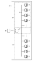
- FIG. 1 is a diagram showing an example of the overall basic configuration of a production planning / execution support system.
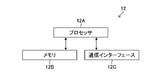
- FIG. 2 is a block diagram showing the configuration of the system DB.
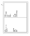
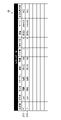
- FIG. 3 is a diagram showing an example of a screen displayed on the display of the device.
- FIG. 4 is a diagram showing an example of a screen displayed on the display of the device.
- FIG. 5 is a diagram showing a screen of a device on which job information is displayed.
- FIG. 6 is a diagram showing a screen of a device on which group information is displayed.
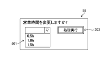
- FIG. 7 is a diagram showing a screen for changing the business hours.
- FIG. 8 is a diagram showing an example of a screen of a device that can be switched by a user operation.
- FIG. 8 is a diagram showing an example of a screen of a device that can be switched by a user operation.
- FIG. 9 is a diagram showing an example of a screen for examining a plan change of each job.
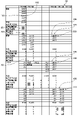
- FIG. 10 is a diagram showing an example of a screen displayed on the display of the device.
- FIG. 11 is a diagram showing an example of a screen in which priority jobs are listed.
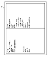
- FIG. 12 is a diagram showing an example of a screen of a list of group production job candidates.
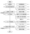
- FIG. 13 is a flowchart showing each process of the production planning / execution support method.
- the production planning / execution support system 10 supports the creation of a production plan in which a plurality of jobs in which at least one of the plurality of processes is set are assigned in chronological order for each process, and the execution of the production plan. It is a system for doing. For example, when the production plan / execution support system 10 processes a plurality of jobs related to a product in a plurality of processes, the production plan / execution support system 10 creates a production plan regarding which job is assigned to which process and in what order. Support the execution of the created production plan.
- the production planning / execution support system 10 can be used by the general manufacturing industry, but here, an example of using the production planning / execution support system 10 in the printing industry of manufacturing printed matter through processes such as printing and cutting will be described.
- FIG. 1 is a diagram showing an overall basic configuration example of the production planning / execution support system 10.
- the production planning / execution support system 10 includes a system DB (DataBase) 12 for performing information processing, a device 14 for a production planning planner, and a device 16 for field workers.
- system DB DataBase
- the system DB 12 (an example of a production plan execution support device) is an on-premises server or a cloud server composed of at least one computer.
- the system DB 12 may be built on a server on which an existing system such as MIS (Management Information System) is built.
- MIS Management Information System
- the system DB 12 is provided with an interface for linking with the existing MIS24 of an external client. Information can be linked between the production planning / execution support system 10 and the MIS 24 via the Internet.
- the device 14 is a personal computer or tablet terminal having an input interface such as a pointing device (not shown) and a display (not shown).
- the device 16 is a personal computer or tablet terminal having an input interface such as a pointing device (not shown) and a display (not shown).
- the device 14 and the device 16 may include a touch panel display in which an input interface and a display are integrated.
- the device 14 and the device 16 are connected to the system DB 12 via the communication network 18.
- the number of devices 14 and 16 connected to the system DB 12 may be any number as long as the specifications of the system DB 12 allow.
- the system DB 12 and the device 14 constitute the production planning unit 20.
- the production planning unit 20 automatically piles up jobs to be processed by each process every unit period (for example, every half day, every day, etc.) determined by the user. Further, the production planning unit 20 supports the detailed adjustment of the production plan by the production planner.
- the system DB 12 and the device 16 constitute an execution support unit 22.
- the device 16 is arranged for each process, for example.
- the execution support unit 22 supports the judgment of the site worker and the site supervisor regarding the order in which the production planning unit 20 should actually work the piled up jobs.
- production planners In the following, production planners, field workers, and field supervisors are not distinguished, and are collectively referred to simply as users.
- FIG. 2 is a block diagram showing the configuration of the system DB 12.
- the system DB 12 includes a processor 12A, a memory 12B, and a communication interface 12C.
- the processor 12A executes the instruction stored in the memory 12B.
- the hardware structure of the processor 12A is various processors (processors) as shown below.
- the various processors include a CPU (Central Processing Unit), which is a general-purpose processor that executes software (programs) and acts as various functional units, and a GPU (Graphics Processing Unit), which is a processor specialized in image processing.
- a circuit specially designed to execute specific processing such as PLD (Programmable Logic Device), ASIC (Application Specific Integrated Circuit), which is a processor whose circuit configuration can be changed after manufacturing FPGA (Field Programmable Gate Array), etc.
- One processing unit may be composed of one of these various processors, or may be composed of two or more processors of the same type or different types (for example, a plurality of FPGAs, or a combination of a CPU and an FPGA, or a CPU and a processing unit. It may be composed of a combination of GPUs).
- a plurality of functional units may be configured by one processor.
- one processor is configured by a combination of one or more CPUs and software, as represented by a computer such as a client or a server. There is a form in which the processor acts as a plurality of functional parts.
- SoC System On Chip
- IC Integrated Circuit
- the hardware-like structure of these various processors is, more specifically, an electric circuit (circuitry) in which circuit elements such as semiconductor elements are combined.
- the memory 12B stores an instruction to be executed by the processor 12A.
- the memory 12B includes a RAM (RandomAccessMemory) and a ROM (ReadOnlyMemory) (not shown).
- the processor 12A uses the RAM as a work area, executes software using various programs and parameters including a production plan execution support program stored in the ROM, and uses the parameters stored in the ROM or the like. Various processes of the system DB 12 are executed.
- the communication interface 12C controls communication via the communication network 18.
- the steps required for production may include, for example, a printing step, a cutting step, a pouch step, and a packing step.
- the process pattern may include, for example, a printing process ⁇ a cutting process ⁇ a pouch process ⁇ a packing process process pattern, a printing process ⁇ a cutting process ⁇ a packing process process pattern, and a printing process ⁇ a pouch process ⁇ a cutting process ⁇ a packing process process pattern. good.
- the process pattern may include various process patterns such as a printing process ⁇ a cutting process ⁇ a UV (UltraViolet) processing process ⁇ a punching process ⁇ a pasting process ⁇ a packing process.
- the system DB 12 is linked in real time with job information of each job and progress information of each job by MIS24.
- job information may include, for example, paper type, base paper size, size after cutting, processing conditions, and shipping date.
- the standard LT (an example of standard progress) referred to here is a consideration of how much the job of each process pattern should proceed with the LT of each process.
- the reference LT may be entered by the user according to past experience.
- the reference LT may be statistically extracted if there is past actual data.
- the reference LT for each job may be estimated by a machine learning model learned with the job information and the current operation status as explanatory variables and the end time of the front-end process and the start time of the back-end process as objective variables.
- the user sets the business hours and the productivity coefficient for each unit period and each process.
- the production capacity of the process in each unit period can be determined by the following formula 1.
- Process production capacity in each unit period standard production capacity x production capacity coefficient ... (Equation 1)
- the user can use the planning function of the system DB 12 via the device 14.
- the system DB 12 incorporates the jobs registered in the system DB 12 into a schedule according to the reference LT and the shipping date, and creates a production plan. That is, the production plan is created by dropping a plurality of jobs for each period and each process based on a predetermined standard LT for each process, and the plurality of jobs are assigned to each process in chronological order. For example, the shipping date of "job1", which is one of the registered jobs, is July 20th, July 19th is a holiday (non-business day), and the process pattern is printing process ⁇ cutting process ⁇ packing process.
- the system DB 12 creates a schedule for "job1": the packing process is completed on July 18, the cutting process is completed on 17th, and the printing process is completed on 16th (see FIG. 3).
- the system DB 12 calculates the estimated time required to process the piled jobs in each process for each unit period after the piled up of all jobs is completed.
- the total setting switching time is the time determined by the initially registered setting switching time and the number of setting switchings.
- the system DB 12 divides jobs into groups according to specified items such as paper type, size, and thickness, and provides an approximate solution obtained by assuming that switching occurs by the number of groups. Used as the number of setting switching.
- the system DB 12 may estimate the number of setting switching from the number of jobs. .. Further, the system DB 12 may predict the number of setting switchings by a machine learning model learned with the number of setting switchings as an objective variable and the job information of the day as an explanatory variable.
- the system DB 12 changes the method of displaying the job name on the screen of the device 14 for jobs that are delayed or are planned to be delayed from the reference LT.
- the system DB 12 may change at least one of the character color, the character font, and the character thickness of the corresponding job on the screen of the device 14, or may add an effect such as blinking. Further, the system DB 12 may change the display step by step depending on the degree of delay.
- the system DB 12 issues an alert in a color display or the like in the column (frame) of the corresponding process in the corresponding period on the screen of the device 14. In this case, it is necessary to deal with non-standard working hours (overtime), or to move some jobs forward or backward. In addition, it is assumed that some circumstances may be desired to be partially adjusted from the plan automatically formulated by the system DB 12 due to some circumstances that are not reflected in the system DB 12.
- FIG. 3 is a diagram showing an example of a screen 50 displayed on the display of the device 14 at the time when the stacking of all jobs is completed. As shown in FIG. 3, on the screen 50, the printing process and the cutting process on July 16, 17, 18, and 20 are displayed.
- the printing process on July 16th includes three jobs, "job1", “job3", and "job7".
- the total number of the three jobs is 1300, and the expected number of switching times is two. Further, the required operating time of these three jobs is 8 hours, and the productivity coefficient is 1. Therefore, the operating time of the printing process on July 16 is 8 hours.
- the business hours on July 16 are 8 hours, and the working hours are 8 hours, so the overtime hours are 0 hours.
- the printing process on July 17th includes three jobs, "job4", "job6", and "job2".
- the total number of the three jobs is 1500, and the expected number of switching is two.
- the required operating time of these three jobs is 9 hours, and the productivity coefficient is 1. Therefore, the operating time of the printing process on July 17 is 9 hours.
- the business hours on July 17 are 8 hours, and the operating hours are 9 hours, so the overtime hours are 1 hour.
- the "business hours” frame 201 and the "overtime hours” frame 202 of the printing process on July 17 are other than that.
- An alert is displayed with a color different from the color of the frame.
- a button 301 for confirming the process is arranged on the screen 50.
- a pop-up 401 for confirming the operation is displayed.
- a button 302 for executing a process is arranged in the pop-up 401. The process is confirmed when the user operates the button 302 by the pointing device of the device 14.
- the user operating a button or the like on the screen using an input interface such as a pointing device may be simply referred to as “operating the button”.
- selecting a job on the screen by the user using an input interface such as a pointing device may be simply referred to as “selecting a job”.
- FIG. 4 is a diagram showing an example of the screen 52 of the device 14 at the time when the stacking of all jobs is completed, as in FIG. 3. As shown in FIG. 4, on the screen 52, jobs of the printing process, the cutting process, the pouch process, and the packing process from July 16 to 20 are displayed.
- the system DB 12 displays the job information of the selected job on the display of the device 14.
- the system DB 12 displays the job information of "job19" on the display of the device 14.
- FIG. 5 is a diagram showing a screen 54 of the device 14 on which the job information of "job19" is displayed.
- the job information includes job name, current process (current process) and status, process completion date, quantity, BOP (Bill of Process), required operating time, number of impositions, paper type, size, and so on. And including remarks.
- the system DB 12 may erase the screen 52 and newly display the screen 54, or may superimpose the screen 52 on the screen 52 to display the screen 54 in a pop-up.
- the user can display the job on the screen 52 shown in FIG. 4 by sorting each item of job information such as paper type and size.
- the system DB 12 sorts and displays jobs according to the specified items.
- the user can group any multiple jobs.
- a button for the user to group jobs may be arranged on the screen 52.
- the system DB 12 displays the breakdown of the jobs constituting the group on the screen of the device 14. This makes it easier for users to consider whether they can move to a place where group production is possible when moving the job forward or backward.
- the pouch process on July 17 includes "Company A product” and "paper container product”.
- the user wants to confirm the group information of "Company A product”
- the user selects the frame 204 of "Company A product”.
- the system DB 12 causes the group information of the "company A product” to be displayed on the screen of the device 14.
- FIG. 6 is a diagram showing a screen 56 of the device 14 on which the group information of "Company A product" is displayed.
- the group information includes a group name, a current process and status, a job list which is a list of jobs included in the group, a total number of sheets, a paper type, a size, and remarks.
- the system DB 12 may erase the screen 52 and newly display the screen 56, or may superimpose the screen 52 on the screen 52 to display the screen 56 in a pop-up.
- job19 is a priority job.
- the character 103 indicating "job19” in the printing process on July 16
- the character 104 indicating "job19” in the cutting process on July 18, and the character “job19” in the pouching process on July 18 are shown.
- the characters 105 and the character 113 indicating "job19” in the packing process on July 19 are each displayed in bold, and the character 106 of "!, Which means a flag, is displayed adjacent to each other.
- the job information of "job19” includes remarks.
- an alert is displayed when a progress delay is expected in the middle of the process.
- “job16”, “job17”, “job18”, and “job19” are completed, and the remaining jobs are "job20" and "job21". ".
- the remaining required operating time is 2 hours
- the productivity coefficient is 1. Therefore, the remaining operating time of the printing process on July 16 is 2 hours.
- the frame 207 indicating the required operating time and the productivity coefficient of the printing process on July 16 and the frame 208 indicating the business hours and overtime hours of the printing process on July 16 are the colors of other frames. Will be alerted in different colors.
- FIG. 7 is a diagram showing a screen 58 for changing the business hours.
- the system DB 12 causes the device 14 to display the screen 58 shown in FIG. 7 in a pop-up manner.
- the screen 58 includes a pull-down menu 501 for selecting an increase in business hours, and a button 303 for confirming the execution of processing. The user can select a desired time from the pull-down menu 501 and operate the button 303 to change the corresponding date and business hours of the process.
- the system DB 12 simulates the load on the source date and the destination date, changes the required time on the source date and the required time on the destination date according to the simulation result, and displays them on the device 14. Let me.
- the system DB 12 can display a screen showing a guideline as to which job has a large load according to the user's operation.
- FIG. 8 is a diagram showing an example of the screen 60 of the device 14 that can be switched from the screen 52 shown in FIG. 4 by a user operation.
- On the screen 60 in each process on each date, each job is displayed with a width corresponding to the time required for the job to be processed. Further, on the screen 60, a line 701 indicating the business hours is displayed, and the user can confirm the jobs that are not completed within the business hours. For example, in the pouch process on July 17, the frame 205 of "Company A product" exceeds the line 701 indicating business hours. Therefore, the user can recognize that the job (group) of "Company A product" is not completed within the business hours.
- row 602 is newly displayed by the user operating the frame 205 of the group "Company A product”.
- the breakdown of “Company A products” is displayed in line 602, and it can be seen that there is one job “job19” and one group "production Gr.1".
- the row 603 is newly displayed.
- the breakdown of "Production Gr.1” is displayed in line 603, and it can be seen that there are two jobs, "job20” and "job21".
- the user can change the job plan by dragging and dropping the frame of each job. For example, the user can move the job to another day or change the order. For example, in the example shown on the screen 60, the delivery date of "job13" is earlier than that of "job21", but if there is a reason to give priority to "job21", the user changes the order of "job13" and "job21". Can be done.
- the user can also move the position of the line 701 by dragging and dropping. If there are many jobs that you want to change the plan and you want to put it back in a batch, a screen for considering the plan change is prepared as follows.
- FIG. 9 is a diagram showing an example of a screen 62 for examining a plan change of each job in the pouch process.
- a list of each job of the pouch process on July 17 is displayed including the delivery date, BOP, and man-hours, respectively.
- a reference line 702 indicating business hours is displayed in the list.
- the user can change the job plan by dragging and dropping the frame of each job. For example, the user can move the job to another day or change the order. For example, in the example shown on the screen 60, the delivery date of "job13" is earlier than that of "job21", but if there is a reason to give priority to "job21", the user changes the order of "job13" and "job21". Can be done.
- the user can also move the position of the line 702 by dragging and dropping.
- the user can postpone the job after line 702 by operating the button 304.
- the line 702 exists between "job 20" and "job 21", and "job 21" is set to be postponed by the operation of the button 304.
- the screen 62 includes a pull-down menu 502 for selecting the extension of the business hours, and a button 305 for confirming the extension of the extension time.
- the user can change the business hours of the pouch process on July 17 by selecting a desired time from the pull-down menu 502 and operating the button 305.
- the position of the line 702 moves according to the changed business hours.
- the user may move the position of the line 702 by a drag and drop operation.
- the system DB 12 displays an alert on the screen of the device 14 for the process in which the business hours are insufficient. This allows the user to consider overtime, forward, and backward on the screen, just as they did at the time of planning.
- the system DB 12 displays a pile of jobs in the process (own process) in which the device 16 is arranged on the screen of the device 16 in each process.
- the plan drafted by the production planning unit 20 is linked with the execution support unit 22, but data in which jobs are piled up for each unit period in another system or the like may be used.
- FIG. 10 is a diagram showing an example of a screen 64 displayed on the display of the device 16 in the pouch process.
- the screen 64 displays a list of jobs piled up in the pouch process (an example of the first process) as of 14:00 on July 16.
- each job group priority, order name, status, delivery date, quantity, number of BOPs, The number of impositions, paper type, size, and required operating time are displayed.
- the priorities are classified by color.
- the priority of "job7” is blue
- the priority of "job8” is black
- the priority of "job2" and “job4" is yellow. .. Therefore, the priority frame 209 of "job7” is filled with blue
- the priority frame 210 of "job8” is black
- the priority frame 211 of "job2” and the priority frame 212 of "job4" are yellow. It has been.
- a job with a black priority is a job that has passed the reference LT
- a job with a yellow priority is a job whose required remaining work time obtained from the current time and the reference LT exceeds the scheduled end time. ..
- the system DB 12 identifiablely displays the jobs whose progress is behind the reference LT among the plurality of jobs.
- the system DB 12 sorts jobs in multiple stages according to arbitrary items such as the order of delay from the reference LT, the order of the most remaining processes, the paper type, and the paper size, according to the operation of the user's device 16. It can be displayed.
- the system DB 12 displays the detailed information of the selected job, causes the remarks column to be described, or refers to the remarks described by another user. Let me do it. Further, the system DB 12 can also extract and display a job having a special note in the remarks column for a job related to the own process of the device 16 regardless of whether or not the job is in the own process at the present time.
- the job information of "job4" is displayed as a pop-up 403 because "job4" is selected by the user.
- the job information includes a job name, current process and status, process completion date, quantity, required operating time (VOP), number of impositions, paper type, size, and remarks.
- the system DB 12 may display a screen similar to the pop-up 403 instead of the screen 64.
- buttons 306 for changing the conditions of the display job a button 307 for displaying the priority job, a button 308 for executing and canceling the grouping, and a group candidate for extracting are performed.
- Button 309 is arranged.
- the system DB 12 causes the device 16 to display the job designated as the priority job by the user regardless of whether or not it is in the own process at that time.
- FIG. 11 is a diagram showing an example of a screen 66 in which priority jobs are displayed in a list.
- "job5" and "job6" are extracted as priority jobs.
- the items displayed for priority jobs are the same as for normal job information, such as job group, priority, order name, current process, status, delivery date, quantity, number of BOPs, number of impositions, paper type, and size. , And the required uptime are listed.
- the priority of "job5" and "job6" is black, and the frames 213 and 214 are painted black.
- Button 306 includes a menu display for specifying extraction conditions for jobs to be displayed in a list. In the menu, you can select "Display own process”, “Display jobs with yellow priority / Display including jobs with blue priority”, and "Display jobs with black priority in previous process”. Placed in.
- the system DB 12 extracts the job under the specified conditions and updates the screen 64.
- Button 309 includes a menu display for extracting the jobs selected on the screen 64 and candidates that can be produced in groups.
- the menus are "Target your own process”, “Extract jobs with yellow priority / Extract including jobs with blue priority”, “Target previous processes”, “Extract running jobs”, and “Work in progress”.
- "Extract jobs in” and “Extract jobs with yellow priority / Extract including jobs with blue priority” are arranged so that they can be selected.
- the system DB 12 lists job candidates (group production job candidates) that can be group-produced together with the jobs selected in the pouch process. (An example of extraction) and display it.
- the system DB 12 sets the job candidates as a job in the same job list as the selected job, a job that is currently processing the previous process and is expected to be completed soon, and a job that is currently processing the previous process. And it is extracted from the jobs corresponding to at least one of the jobs scheduled to be processed within the same period as the selected job. Further, the system DB 12 extracts job candidates from the selected job and jobs having the same items such as paper type and paper size.
- the job in the same job list refers to a job in the list of jobs displayed on the device 16 in the same process (for example, own process) as shown on the screen 64.
- the pre-process refers to the process immediately before the own process. Jobs that are scheduled to be processed within the same period as the selected job are jobs in the same job list, as well as jobs that have not yet reached that process and are in the previous process, but are selected jobs. Refers to a job whose standard progress is to pass through the own process within the same deadline as.
- FIG. 12 is a diagram showing an example of the screen 68 of the list of group production job candidates.
- the screen 68 is a screen displayed when the frame 215 of the size “550 * 400” of the job “job2” (an example of the first job) of the group 1 is selected in the screen 64 shown in FIG. be.
- job14 "job15", "job16”, and "job17" are extracted as group production candidate jobs.
- the system DB 12 is extracting jobs of the same size "550 * 400".
- the items displayed for group production job candidates are the same as normal job information, and the priority, order name, current process, status, delivery date, quantity, number of BOPs, number of impositions, paper type, and size of each job are displayed. , And the required uptime are listed.
- the characters indicating the size "550 * 400” of "job14”.
- the character 108 indicating the size "550 * 400” of "job15”
- the character 109 indicating the size "550 * 400” of "job16”
- the character 110 indicating the size "550 * 400” of "job17”, respectively. It is displayed in a color (for example, red) different from the other characters on the screen 68.
- the system DB 12 displays them as a group.
- "job14" and “job15” are selected and confirmed as the job of group 1
- the frame 216 of the group of "job14” and the frame 217 of the group of "job15” are selected.
- a character 111 and a character 112 indicating "group 1" are displayed in the above, respectively. Grouped jobs cannot be selected by the user when considering another group production target.
- the item of job information for determining whether or not the job is a group production target job can be set in the master data of the system DB 12 for each process.
- the size to be referred to differs depending on whether the size to be referred to is the size of the base paper or the size of the product before and after the cutting process.
- the system DB 12 can also display operation information such as whether or not the status is operating when displaying the job list of the previous process.
- FIG. 13 is a flowchart showing each process of the production plan / execution support method (an example of the production plan execution support method) which is the operation flow of the production plan / execution support system 10.
- the production planning / execution support method is roughly divided into a production planning method and an execution support method.
- the production planning unit 20 formulates a job production plan for each unit period and each process.
- the execution support method including steps S4 to S6, the execution support unit 22 determines how to execute the work.
- step S1 the user sets the business hours of each process, the production capacity, the setting switching time, the standard LT for each process pattern (BOP), and the grouping for each process at the time of system introduction and process review. Master data such as conditions are registered in the system DB 12 (step S-1).
- the system DB 12 can also analyze the initial setting values such as the production capacity and the standard LT from the past actual data and automatically set them.
- step S2-1 the user first registers the job information of the ordered job (step S2-1).
- the job information can be read even in the production planning / execution support system 10 by separately preparing an interface for cooperation with the existing job DB such as MIS24 already used at the installation destination. be.
- the existing job DB such as MIS24 already used at the installation destination.
- the system DB 12 automatically generates a pile of temporary jobs according to the process completion date and the reference LT, and creates a temporary production plan for each period and each process (step S2-2).
- the screen 52 shown in FIG. 4 is displayed on the device 14 as an example.
- step S2 In the provisional production plan determined in step S2, there may be a process in which the load is overloaded in a certain period, or there may be a job whose order is desired to be changed due to circumstances not included in the registration information. Therefore, in the user adjustment step of step S3, the user adjusts the business hours, specifies the priority job, describes the remarks column, and the like on the screen of the device 14, and then finalizes the plan (step S3-1). ..
- the screen 60 shown in FIG. 8 allows the user to select desired jobs at once, and can make adjustments efficiently.
- step S3 the production plan is finalized.
- system DB 12 can also set job grouping according to the user's operation on the device 14.
- the system DB 12 causes the device 14 to display a screen similar to the screen 68 shown in FIG.
- the group set in the device 14 is also displayed on the screen in a grouped state in the device 16.
- the ordering source customers may be grouped and displayed in one block (frame). It is conceivable to set the display method to other than each job or group.
- the present embodiment can be used in combination with the production visualization system.
- the production plan / execution support system 10 can be utilized as a system that has both production plan execution support and production visualization.
- the system DB 12 displays a list of jobs on the screen of the device 16. The user in each process can confirm the job on the screen of the device 16. At that time, the system DB 12 acquires information on how much time each job has remaining with respect to the reference LT (step S4-1).
- the system DB 12 displays jobs that have passed the reference LT in black, jobs that exceed the required remaining work time from the current time in yellow, other jobs in blue, and so on, depending on the progress. Determination (step S4-2). Then, the system DB 12 displays these on the screen of the device 16 so that they can be understood at a glance (step S4-3). For example, the screen 64 shown in FIG. 10 corresponds to the screen at this time.
- system DB 12 may display the jobs sorted by the progress with respect to the reference LT and each item of each job information, the priority job specified at the time of planning, and the job with special notes in the remarks column. It may be displayed (step S4-3). This allows the user to efficiently think about what to do with each job based on the screen display.
- step S5 the user first selects a job displayed on the screen of the device 16.
- the system DB 12 displays a list of job candidates that can be group-produced among the jobs in the own process and the jobs in the previous process of the selected job on the screen of the device 16 (step S5-1, an example of the candidate display step).
- the list display may be a pop-up display.
- the screen 68 shown in FIG. 12 is displayed on the device 16 as an example.
- the system DB 12 groups the checked jobs on the screen, and thereafter, sorts and the like are treated as one group (step S5-2). Therefore, grouped jobs are not extracted as candidates for jobs that can be produced in another group. Here, it is possible to create multiple groups.
- Step S6 the system DB 12 compares the remaining operating time with the remaining required working time, and when the working time is insufficient, displays an alert on the corresponding process on the screen of the device 14.
- Step S6-1 the color of the frame 207 and the frame 208 of the screen 52 shown in FIG. 4, which is different from the other frames, corresponds to this alert display.
- the user adjusts the production plan on the screen in the same way as when making the plan for the alert display (step S6-2). That is, the user decides overtime work for the corresponding process, and puts back the job that needs to be put back. As a result, it is possible to respond to the delay in progress at an early stage. For example, by displaying the screen 62 shown in FIG. 9 on the device 16, it becomes easy to readjust the production plan of the job.
- the production planning / execution support system 10 causes devices in each process such as a printing machine and a cutting machine to execute a job. As a result, the work is executed in each process.
- the jobs to be processed are automatically piled up for each unit period and each process. It can help adjust field users to suit different situations and determine in what order field workers should process those jobs. In addition, even if the process order is not uniform and a huge amount of jobs are used, it is possible to formulate a production plan that realizes the minimum on-time delivery regardless of know-how.
- this embodiment it is possible to efficiently formulate an effective production plan according to the actual situation of the site by handling it by a manager having know-how.
- the required production capacity guideline is known, it is possible to make an appropriate resource input decision.
- the sales department can see the margin of production capacity, it is possible to judge the order / set the delivery date without communicating with the production department.
- it is clarified which workers can and cannot achieve the objectively planned production plan it is possible to make a personnel evaluation based on the actual results.
- companies that prepare users for each of multiple departments and manufacture them independently can use this system to standardize work across departments.
- This embodiment is applicable to the execution of the production plan of the manufacturing industry, preferably the production plan of the printing industry and its execution, and more preferably to the printing industry of manufacturing small lots and various kinds of products.
- Production planning / execution support system 12 ... System DB 12A ... Processor 12B ... Memory 12C ... Communication interface 14 ... Device 16 ... Device 18 ... Communication network 20 ... Production planning department 22 ... Execution support department 50, 52, 54, 56, 58, 60, 62, 64, 66, 68 ... Screens 101 to 113 ... Characters 201 to 217 ... Frames 301 to 309 ... Buttons 401 to 403 ... Pop-ups 501, 502 ... Pull-down menus 601-603 ... Lines 701, 702 ... Lines S1-S6 Each step of the production plan execution support method
Landscapes
- Engineering & Computer Science (AREA)
- General Physics & Mathematics (AREA)
- Manufacturing & Machinery (AREA)
- Business, Economics & Management (AREA)
- Physics & Mathematics (AREA)
- General Health & Medical Sciences (AREA)
- Marketing (AREA)
- Quality & Reliability (AREA)
- Health & Medical Sciences (AREA)
- Economics (AREA)
- General Engineering & Computer Science (AREA)
- Human Resources & Organizations (AREA)
- Automation & Control Theory (AREA)
- Primary Health Care (AREA)
- Strategic Management (AREA)
- Tourism & Hospitality (AREA)
- General Business, Economics & Management (AREA)
- Theoretical Computer Science (AREA)
- General Factory Administration (AREA)
- Management, Administration, Business Operations System, And Electronic Commerce (AREA)
Abstract
効率のよいジョブの処理方法の判断を支援する生産計画実行支援装置、生産計画実行支援方法およびプログラムを提供する。複数の工程のうちの少なくとも1つの工程がそれぞれ設定された複数のジョブが工程毎に割り当てられた生産計画の実行を支援する生産計画実行支援装置において、第1の工程の単位期間毎のジョブの一覧であって、あらかじめ定められた第1の工程の標準進度よりも進度が遅れているジョブを識別可能にジョブの一覧を表示させ、一覧表示されたジョブの中からユーザーが選択したジョブを受け付け、選択されたジョブとともに第1の工程においてグループ生産が可能なジョブの候補のリストを表示させる。
Description
本発明は生産計画実行支援装置、生産計画実行支援方法およびプログラムに係り、特に生産計画を実行する際の現場ユーザーの判断および事務作業を効率化する技術に関する。
後加工工程の多い印刷業等のように、小ロット多品種を扱う製造業では、製品毎に必要な工程が異なり、また1日当たりに処理する製品の数も膨大になる。このため、効率的な生産計画を立てて生産することが難しい。
このような課題に対し、製品毎に多種多様な工程を通る製造現場向けの生産計画の手法も提案されている。例えば、特許文献1には、ジョブを処理するために必要なタスクを抽出し、タスクを処理するために使用する生産機器・生産計画日時等を含めた生産計画データを作成する装置が記載されている。
特許文献1に開示された装置によれば、ユーザーの労力を抑え、各工程のタイムスケジュールまで含めた生産計画を作成することができる。その一方、前提条件として各ジョブの情報から生産にかかる所要時間の予測を正確に行う必要がある。
しかしながら、顧客からの細かな注文等によって各工程の難易度が変わることがあり、時間予測が難しいという問題点があった。また、機械の故障等により生産現場において計画通りに処理できない場合があった。このため、結局ユーザーがアナログに管理しているケースが多いという実態がある。
本発明はこのような事情に鑑みてなされたもので、効率のよいジョブの処理方法の判断を支援する生産計画実行支援装置、生産計画実行支援方法およびプログラムを提供することを目的とする。
上記目的を達成するための生産計画実行支援装置の一の態様は、複数の工程のうちの少なくとも1つの工程がそれぞれ設定された複数のジョブが工程毎に割り当てられた生産計画の実行を支援する生産計画実行支援装置において、プロセッサに実行させるための命令を記憶するメモリと、メモリに記憶された命令を実行するプロセッサと、を備え、プロセッサは、第1の工程の単位期間毎のジョブの一覧であって、あらかじめ定められた第1の工程の標準進度よりも進度が遅れているジョブが識別可能なジョブの一覧を表示させ、表示されたジョブの一覧の中からユーザーが選択した第1のジョブを受け付け、第1のジョブとともに第1の工程においてグループ生産が可能なジョブの候補のリストを表示させる、生産計画実行支援装置である。
本態様によれば、あらかじめ定められた標準進度よりも進度が遅れているジョブが識別可能な第1の工程のジョブの一覧を表示させ、ユーザーが選択したジョブを受け付け、選択されたジョブとともに第1の工程においてグループ生産が可能なジョブの候補のリストを表示させるようにしたので、効率のよいジョブの処理方法の判断を支援することができる。
プロセッサは、第1の工程の稼働状況、および生産計画に基づいてグループ生産が可能なジョブの候補を抽出することが好ましい。これにより、グループ生産が可能なジョブの候補を適切に抽出することができる。
プロセッサは、第1の工程の前工程を処理中のジョブの中からグループ生産が可能なジョブの候補を抽出することが好ましい。これにより、グループ生産が可能なジョブの候補を適切に抽出することができる。
プロセッサは、グループ生産が可能なジョブの候補の中からユーザーが選択した第2のジョブを受け付け、第2のジョブを第1の工程において第1のジョブとともにグループ生産するジョブとして確定させることが好ましい。これにより、所望のジョブをグループ生産させることができる。
プロセッサは、標準進度に対する進捗、又はジョブの情報の項目でソートして複数のジョブの一覧を表示させることが好ましい。これにより、グループ生産すべきジョブをユーザーが認識することができる。
プロセッサは、現時刻と標準進度とから求めた必要な残り作業時間とを比較して予定終了時刻を超えているジョブを識別可能に表示させることが好ましい。これにより、優先度の高いジョブをユーザーが認識することができる。
プロセッサは、標準進度よりも進度が遅れているジョブの色を変更して表示させることが好ましい。これにより、標準進度よりも進度が遅れているジョブをユーザーが識別することができる。
生産計画は、あらかじめ定められた工程毎の標準進度に基づいて、期間毎、および工程毎に複数のジョブを落とし込んで作成されることが好ましい。本態様によれば、このように作成された生産計画について効率のよいジョブの処理方法の判断を支援することができる。
複数の工程は、印刷の工程を含むことが好ましい。本態様は、印刷物の製造を行う印刷業に好適である。
上記目的を達成するための生産計画実行支援方法の一の態様は、複数の工程のうちの少なくとも1つの工程がそれぞれ設定された複数のジョブが工程毎に割り当てられた生産計画の実行を支援する生産計画実行支援方法において、第1の工程の単位期間毎のジョブの一覧であって、あらかじめ定められた第1の工程の標準進度よりも進度が遅れているジョブが識別可能なジョブの一覧を表示させるジョブ表示ステップと、表示されたジョブの一覧の中からユーザーが選択した第1のジョブを受け付ける受付ステップと、第1の工程において第1のジョブとともにグループ生産が可能なジョブの候補のリストを表示させる候補表示ステップと、を備える生産計画実行支援方法である。
本態様によれば、あらかじめ定められた標準進度よりも進度が遅れているジョブが識別可能な第1の工程のジョブの一覧を表示させ、ユーザーが選択したジョブを受け付け、選択されたジョブとともに第1の工程においてグループ生産が可能なジョブの候補のリストを表示させるようにしたので、効率のよいジョブの処理方法の判断を支援することができる。
上記目的を達成するためのプログラムの一の態様は、上記の生産計画実行支援方法をコンピュータに実行させるためのプログラムである。このプログラムが記録された、コンピュータが読み取り可能な非一時的記憶媒体も本態様に含んでよい。
本態様によれば、あらかじめ定められた標準進度よりも進度が遅れているジョブを識別可能に第1の工程のジョブの一覧を表示させ、ユーザーが選択したジョブを受け付け、選択されたジョブとともに第1の工程においてグループ生産が可能なジョブの候補のリストを表示させるようにしたので、効率のよいジョブの処理方法の判断を支援することができる。
本発明によれば、効率のよいジョブの処理方法の判断を支援することができる。
以下、添付図面に従って本発明の好ましい実施形態について詳説する。
〔生産計画/実行支援システムの基本構成〕
生産計画/実行支援システム10は、複数の工程のうちの少なくとも1つの工程がそれぞれ設定された複数のジョブが工程毎に時系列的に割り当てられた生産計画の作成、および生産計画の実行を支援するためのシステムである。例えば、生産計画/実行支援システム10は、製品に関する複数のジョブを複数の工程において処理する際に、どのジョブをどの工程に割り付けてどのような順番で処理するかについての生産計画を作成し、作成した生産計画の実行を支援する。生産計画/実行支援システム10は、製造業一般に利用可能であるが、ここでは印刷、断裁等の工程を経て印刷物を製造する印刷業に利用する例に説明する。
生産計画/実行支援システム10は、複数の工程のうちの少なくとも1つの工程がそれぞれ設定された複数のジョブが工程毎に時系列的に割り当てられた生産計画の作成、および生産計画の実行を支援するためのシステムである。例えば、生産計画/実行支援システム10は、製品に関する複数のジョブを複数の工程において処理する際に、どのジョブをどの工程に割り付けてどのような順番で処理するかについての生産計画を作成し、作成した生産計画の実行を支援する。生産計画/実行支援システム10は、製造業一般に利用可能であるが、ここでは印刷、断裁等の工程を経て印刷物を製造する印刷業に利用する例に説明する。
図1は、生産計画/実行支援システム10の全体の基本構成例を示す図である。生産計画/実行支援システム10は、情報処理を行うシステムDB(Data Base)12と、生産計画立案者用のデバイス14と、現場作業者用のデバイス16と、を備える。
システムDB12(生産計画実行支援装置の一例)は、少なくとも1つのコンピュータによって構成されるオンプレミスサーバー、又はクラウドサーバーである。システムDB12は、MIS(Management Information System)等の既存のシステムが構築されたサーバーに構築されていてもよい。
システムDB12は、外部のクライアントの既存のMIS24との連携インターフェースを備える。生産計画/実行支援システム10とMIS24とは、インターネットを介して情報連携を行うことができる。
デバイス14は、不図示のポインティングデバイス等の入力インターフェースおよび不図示のディスプレイを有するパーソナルコンピューター、又はタブレット端末である。デバイス16は、不図示のポインティングデバイス等の入力インターフェースおよび不図示のディスプレイを有するパーソナルコンピューター、又はタブレット端末である。デバイス14およびデバイス16は、入力インターフェースおよびディスプレイを一体化したタッチパネルディスプレイを備えてもよい。デバイス14およびデバイス16は、通信ネットワーク18を介してシステムDB12に接続される。システムDB12に接続されるデバイス14およびデバイス16の数は、システムDB12のスペックの許す限り任意の数でよい。
システムDB12およびデバイス14は、生産計画部20を構成する。生産計画部20は、ユーザーが定める単位期間毎(例えば、半日毎、一日毎等)に、各工程が処理すべきジョブについて自動的に山積みを行う。さらに、生産計画部20は、生産計画立案者による生産計画の詳細な調整を支援する。
システムDB12およびデバイス16は、実行支援部22を構成する。デバイス16は、例えば工程毎に配置される。実行支援部22は、生産計画部20が山積みしたジョブをどのような順番で実際に作業すべきかについて、現場作業者および現場監督者の判断を支援する。
以下においては、生産計画立案者、現場作業者、および現場監督者を区別せず、総称して単にユーザーと呼ぶ。
〔システムDBの構成〕
図2は、システムDB12の構成を示すブロック図である。システムDB12は、プロセッサ12Aと、メモリ12Bと、通信インターフェース12Cと、を備える。
図2は、システムDB12の構成を示すブロック図である。システムDB12は、プロセッサ12Aと、メモリ12Bと、通信インターフェース12Cと、を備える。
プロセッサ12Aは、メモリ12Bに記憶された命令を実行する。プロセッサ12Aのハードウェア的な構造は、次に示すような各種のプロセッサ(processor)である。各種のプロセッサには、ソフトウェア(プログラム)を実行して各種の機能部として作用する汎用的なプロセッサであるCPU(Central Processing Unit)、画像処理に特化したプロセッサであるGPU(Graphics Processing Unit)、FPGA(Field Programmable Gate Array)等の製造後に回路構成を変更可能なプロセッサであるPLD(Programmable Logic Device)、ASIC(Application Specific Integrated Circuit)等の特定の処理を実行させるために専用に設計された回路構成を有するプロセッサである専用電気回路等が含まれる。
1つの処理部は、これら各種のプロセッサのうちの1つで構成されていてもよいし、同種又は異種の2つ以上のプロセッサ(例えば、複数のFPGA、又はCPUとFPGAの組み合わせ、あるいはCPUとGPUの組み合わせ)で構成されてもよい。また、複数の機能部を1つのプロセッサで構成してもよい。複数の機能部を1つのプロセッサで構成する例としては、第1に、クライアント又はサーバー等のコンピュータに代表されるように、1つ以上のCPUとソフトウェアの組合せで1つのプロセッサを構成し、このプロセッサが複数の機能部として作用させる形態がある。第2に、SoC(System On Chip)等に代表されるように、複数の機能部を含むシステム全体の機能を1つのIC(Integrated Circuit)チップで実現するプロセッサを使用する形態がある。このように、各種の機能部は、ハードウェア的な構造として、上記各種のプロセッサを1つ以上用いて構成される。
さらに、これらの各種のプロセッサのハードウェア的な構造は、より具体的には、半導体素子等の回路素子を組み合わせた電気回路(circuitry)である。
メモリ12Bは、プロセッサ12Aに実行させるための命令を記憶する。メモリ12Bは、不図示のRAM(Random Access Memory)、およびROM(Read Only Memory)を含む。プロセッサ12Aは、RAMを作業領域とし、ROMに記憶された生産計画実行支援プログラムを含む各種のプログラムおよびパラメータを使用してソフトウェアを実行し、かつROM等に記憶されたパラメータを使用することで、システムDB12の各種の処理を実行する。
通信インターフェース12Cは、通信ネットワーク18を介した通信を制御する。
〔生産計画部〕
《初期設定》
ユーザーは、システムDB12に、標準的な単位期間あたりの営業時間、生産に必要な各工程の標準生産能力および設定切替所要時間、工程パターン毎の基準LT(Lead Time)、等のマスターデータをあらかじめ登録しておく。生産に必要な工程は、例えば印刷工程、断裁工程、パウチ工程、および梱包工程を含んでもよい。工程パターンは、例えば印刷工程→断裁工程→パウチ工程→梱包工程の工程パターン、印刷工程→断裁工程→梱包工程の工程パターン、および印刷工程→パウチ工程→断裁工程→梱包工程の工程パターンを含んでもよい。その他、工程パターンには、印刷工程→断裁工程→UV(UltraViolet)加工工程→抜き工程→貼り工程→梱包工程等の様々な工程パターンを含んでもよい。
《初期設定》
ユーザーは、システムDB12に、標準的な単位期間あたりの営業時間、生産に必要な各工程の標準生産能力および設定切替所要時間、工程パターン毎の基準LT(Lead Time)、等のマスターデータをあらかじめ登録しておく。生産に必要な工程は、例えば印刷工程、断裁工程、パウチ工程、および梱包工程を含んでもよい。工程パターンは、例えば印刷工程→断裁工程→パウチ工程→梱包工程の工程パターン、印刷工程→断裁工程→梱包工程の工程パターン、および印刷工程→パウチ工程→断裁工程→梱包工程の工程パターンを含んでもよい。その他、工程パターンには、印刷工程→断裁工程→UV(UltraViolet)加工工程→抜き工程→貼り工程→梱包工程等の様々な工程パターンを含んでもよい。
システムDB12は、MIS24により、各ジョブのジョブ情報、および各ジョブの進捗情報についてリアルタイムに連携されている。ジョブ情報は、例えば紙種、原紙サイズ、断裁後サイズ、加工条件、および出荷日を含んでもよい。
なお、ここでいう基準LT(標準進度の一例)は、各工程パターンのジョブが、各工程のLTをどの程度で進めていくのが標準かを考慮したものである。基準LTは、過去の経験に従ってユーザーにより入力されてもよい。基準LTは、過去の実績データがあるのであれば、統計的に抽出されてもよい。また、ジョブ情報および現在の稼働状況を説明変数、前工程の終了時間および後工程の開始時間を目的変数、として学習された機械学習モデルによって、ジョブ毎の基準LTが見積もられてもよい。
また、ユーザーは、単位期間毎および工程毎の営業時間および生産力係数を設定する。各単位期間における工程の生産能力は、以下の式1により定めることができる。
各単位期間における工程の生産能力=標準生産能力×生産力係数 …(式1)
各単位期間における工程の生産能力=標準生産能力×生産力係数 …(式1)
例えば、標準生産能力が1000枚/時間の設備の工程において、普段1人作業のところを2人に増員して1.5倍の生産速度が見込まれる場合、その期間の生産能力は、
増員中の生産能力=1000×1.5=1500枚/時間
である。
増員中の生産能力=1000×1.5=1500枚/時間
である。
《投入計画作成》
ユーザーは、デバイス14を介してシステムDB12の計画立案機能を用いることができる。システムDB12は、システムDB12に登録されたジョブを、基準LTおよび出荷日に応じてスケジュールに落とし込み、生産計画を作成する。すなわち、生産計画は、あらかじめ定められた工程毎の基準LTに基づいて、期間毎、および工程毎に複数のジョブを落とし込んで作成され、複数のジョブが工程毎に時系列的に割り当てられる。例えば、登録されたジョブの1つである「job1」の出荷日が7月20日であり、7月19日が休日(非営業日)であり、工程パターンが印刷工程→断裁工程→梱包工程であり、基準LTが印刷工程=1日、断裁工程=1日、梱包工程=1日、出荷納期バッファー=1日であるとする。この場合、システムDB12は、「job1」について、7月18日に梱包工程完了、17日に断裁工程完了、16日に印刷工程完了、というスケジュールを作成する(図3参照)。
ユーザーは、デバイス14を介してシステムDB12の計画立案機能を用いることができる。システムDB12は、システムDB12に登録されたジョブを、基準LTおよび出荷日に応じてスケジュールに落とし込み、生産計画を作成する。すなわち、生産計画は、あらかじめ定められた工程毎の基準LTに基づいて、期間毎、および工程毎に複数のジョブを落とし込んで作成され、複数のジョブが工程毎に時系列的に割り当てられる。例えば、登録されたジョブの1つである「job1」の出荷日が7月20日であり、7月19日が休日(非営業日)であり、工程パターンが印刷工程→断裁工程→梱包工程であり、基準LTが印刷工程=1日、断裁工程=1日、梱包工程=1日、出荷納期バッファー=1日であるとする。この場合、システムDB12は、「job1」について、7月18日に梱包工程完了、17日に断裁工程完了、16日に印刷工程完了、というスケジュールを作成する(図3参照)。
システムDB12は、全てのジョブの山積みが終了後、単位期間毎の各工程の山積みされたジョブの処理にかかる目安の時間を算出する。ジョブの処理にかかる目安の時間は、例えば、下記の式2によって算出する。
ジョブの処理にかかる目安の時間=合計枚数÷生産能力+合計設定切替時間 …(式2)
ジョブの処理にかかる目安の時間=合計枚数÷生産能力+合計設定切替時間 …(式2)
合計設定切替時間は、初期登録された1回あたりの設定切替時間および設定切替の回数で定まる時間である。しかしながら、厳密な設定切替の回数を予測することは難しい。このため、本実施形態では、システムDB12は、紙種、サイズ、および厚み等の指定の項目でジョブをグループに分け、グループの数だけ切替が発生すると仮定することで得られる近似的な解を設定切替の回数として用いる。また、過去の実績データから設定切替の回数とジョブの数の比率がおおよそ一定であるという分析結果が得られた場合には、システムDB12は、ジョブの数から設定切替の回数を見積もってもよい。さらに、システムDB12は、設定切替回数を目的変数、その日のジョブ情報を説明変数、として学習された機械学習モデルによって、設定切替の回数を予測してもよい。
システムDB12は、基準LTから遅れている、又は遅れる計画となっているジョブについて、デバイス14の画面上のジョブ名の表示の方式を変更する。例えば、システムDB12は、デバイス14の画面の該当するジョブの文字の色、文字のフォントおよび文字の太さの少なくとも1つを変更してもよいし、点滅等の効果を加えてもよい。また、システムDB12は、遅れの度合いによって段階的に表示を変更してもよい。
システムDB12は、ジョブの処理にかかる目安の時間が営業時間を超える場合は、デバイス14の画面の該当する期間の該当する工程の欄(枠)に色表示等でアラートを出す。この場合、標準勤務時間外(残業)による対応、又は一部のジョブの前倒しもしくは後ろ倒しが必要になる。また、システムDB12には反映されていない何かしらの事情により、システムDB12が自動的に立案した計画から一部調整したい場合が想定される。
図3は、全てのジョブの山積みが終了した時点でのデバイス14のディスプレイに表示される画面50の一例を示す図である。図3に示すように、画面50では、7月16日、17日、18日、および20日の印刷工程および断裁工程について表示されている。
7月16日の印刷工程は、3つのジョブである「job1」、「job3」、および「job7」が含まれる。3つのジョブの合計枚数は1300枚であり、切替見込回数は2回である。また、この3つのジョブの必要稼働時間は8時間であり、生産力係数は1である。したがって、7月16日の印刷工程の稼働時間は8時間となる。また、7月16日の営業時間は8時間であり、稼働時間が8時間であるため残業時間は0時間である。
なお、ジョブの1つである「job3」は、基準LTから遅れている、又は遅れる計画となっている。このため、画面50において、7月16日の印刷工程における「job3」を示す文字101、および断裁工程における「job3」を示す文字102は、他のジョブを示す色とは異なる色で表示される。
7月17日の印刷工程は、3つのジョブである「job4」、「job6」、および「job2」が含まれる。3つのジョブの合計枚数は1500枚であり、切替見込回数は2回である。この3つのジョブの必要稼働時間は9時間であり、生産力係数は1である。したがって、7月17日の印刷工程の稼働時間は9時間となる。また、7月17日の営業時間は8時間であり、稼働時間が9時間であるため残業時間は1時間である。
このように、7月17日の印刷工程は営業時間内に終了できないことを示すため、7月17日の印刷工程の「営業時間」の枠201と「残業時間」の枠202とは、その他の枠の色とは異なる色によってアラート表示される。
また、画面50には、処理を確定するためのボタン301が配置される。ユーザーがデバイス14のポインティングデバイスによってボタン301を操作すると、操作を確認するためのポップアップ401が表示される。ポップアップ401には、処理を実行するためのボタン302が配置される。ユーザーがデバイス14のポインティングデバイスによってボタン302を操作することで、処理が確定する。
なお、以下において、ユーザーがポインティングデバイス等の入力インターフェースを用いて画面内のボタン等を操作することを、単に「ボタンを操作する」という場合がある。同様に、ユーザーがポインティングデバイス等の入力インターフェースを用いて画面内のジョブを選択することを、単に「ジョブを選択する」という場合がある。
《ユーザーによる調整》
図4は、図3と同様に、全てのジョブの山積みが終了した時点でのデバイス14の画面52の一例を示す図である。図4に示すように、画面52では、7月16日~20日の印刷工程、断裁工程、パウチ工程、および梱包工程のジョブについて表示されている。
図4は、図3と同様に、全てのジョブの山積みが終了した時点でのデバイス14の画面52の一例を示す図である。図4に示すように、画面52では、7月16日~20日の印刷工程、断裁工程、パウチ工程、および梱包工程のジョブについて表示されている。
画面52が表示された状態において、ユーザーによって山積みされたジョブのうちのいずれかのジョブが選択されると、システムDB12は、選択されたジョブのジョブ情報をデバイス14のディスプレイに表示させる。
例えば、ユーザーが「job19」のジョブ情報を確認したい場合、ユーザーは「job19」の枠203を選択する。この操作に対して、システムDB12は、「job19」のジョブ情報をデバイス14のディスプレイに表示させる。
図5は、「job19」のジョブ情報が表示されたデバイス14の画面54を示す図である。図5に示すように、ジョブ情報は、ジョブ名、現工程(現在の工程)とステータス、工程完了日、数量、BOP(Bill of Process)、必要稼働時間、面付け数、紙種、サイズ、および備考を含む。システムDB12は、画面52を消去して新たに画面54を表示させてもよいし、画面52に重ねて画面54をポップアップ表示させてもよい。
また、ユーザーは、図4に示す画面52において、紙種およびサイズ等、ジョブ情報の項目毎にソートをかけてジョブを表示させることができる。システムDB12は、指定された項目によってジョブをソートして表示させる。
また、ユーザーは、任意の複数のジョブをグループ化することができる。画面52にユーザーがジョブをグループ化するためのボタンを配置してもよい。複数のジョブからなるグループがユーザーによって選択されると、システムDB12は、デバイス14の画面にグループを構成するジョブの内訳を表示させる。これにより、ユーザーがジョブを前倒し又は後ろ倒しにする際に、グループ生産可能な場所へ移動できるか検討しやすくなる。
例えば、図4に示す画面52において、7月17日のパウチ工程は、「A社品」および「紙器品」を含む。ユーザーが「A社品」のグループ情報を確認したい場合、ユーザーは「A社品」の枠204を選択する。この操作に対して、システムDB12は、「A社品」のグループ情報をデバイス14の画面に表示させる。
図6は、「A社品」のグループ情報が表示されたデバイス14の画面56を示す図である。図6に示すように、グループ情報は、グループ名、現工程とステータス、グループに含まれるジョブのリストであるジョブリスト、合計枚数、紙種、サイズ、および備考を含む。システムDB12は、画面52を消去して新たに画面56を表示させてもよいし、画面52に重ねて画面56をポップアップ表示させてもよい。
優先すべきジョブ、納期の短い特急品のジョブ、および生産時に注意が必要なジョブには、ユーザーは該当するジョブの位置にフラグを立てたり、備考を記載したりすることも可能である。図4に示す画面52においては、「job19」が優先ジョブである。画面52においては、7月16日の印刷工程における「job19」を示す文字103、7月18日の断裁工程における「job19」を示す文字104、7月18日のパウチ工程における「job19」を示す文字105、7月19日の梱包工程における「job19」を示す文字113は、それぞれ太字で表示され、かつフラグを意味する「!」の文字106が隣接して表示されている。また、図5に示したように、「job19」のジョブ情報は備考を含む。
このフラグおよび備考は、各工程のデバイス16の画面においてユーザーが確認することも可能である。
また、画面52では、途中経過で進捗遅れが見込まれる場合にアラートが表示される。例えば、画面52に示す例では、7月16日の印刷工程では、「job16」、「job17」、「job18」、及び「job19」が終了しており、残りのジョブが「job20」と「job21」である。ここで、7月16日の印刷工程は、残りの必要稼働時間が2時間であり、生産力係数が1である。したがって、7月16日の印刷工程の残りの稼働時間は2時間である。これに対し、7月16日の残りの営業時間は1時間であるために残業時間が1時間発生し、残業による対応をしない場合には進捗遅れが発生する。この場合、7月16日の印刷工程の必要稼働時間及び生産力係数を示す枠207と、7月16日の印刷工程の営業時間及び残業時間を示す枠208とは、その他の枠の色とは異なる色によってアラート表示される。
さらに、システムDB12は、残業による対応をする場合に、営業時間を画面上で容易に変更できる機能を有している。図7は、営業時間の変更をするための画面58を示す図である。図4に示す画面52の任意の日付および任意の工程の「営業時間」の枠が選択されると、システムDB12は、デバイス14に図7に示す画面58をポップアップ表示させる。図7に示すように、画面58は、営業時間の増加分を選択させるためのプルダウンメニュー501、および処理の実行を確定するためのボタン303を含む。ユーザーは、プルダウンメニュー501から所望の時間を選択し、ボタン303を操作することで、該当する日付および工程の営業時間を変更することができる。
ユーザーがジョブを前倒し又は後ろ倒しをしたい場合は、ユーザーは画面上で所望のジョブを異なる日付に移動させればよい。この場合、システムDB12は、移動元の日付の負荷および移動先の日付をシミュレーションし、移動元の日付の所要時間および移動先の日付の所要時間をシミュレーション結果に応じて変更してデバイス14に表示させる。
また、システムDB12は、ユーザーの操作に応じて、どのジョブがどの程度の負荷の大きさなのか目安がわかる画面を表示させることも可能である。図8は、図4に示す画面52からユーザーの操作によって切り替えられるデバイス14の画面60の一例を示す図である。画面60では、各日付の各工程において、ジョブが処理に必要な時間に応じた幅で各ジョブが表示される。また、画面60では、営業時間を示す線701が表示されており、営業時間内に終了しないジョブをユーザーが確認することができる。例えば、7月17日のパウチ工程において、「A社品」の枠205が営業時間を示す線701を超えている。このため、ユーザーは、「A社品」のジョブ(グループ)が営業時間内に終了しないことを認識することができる。
ここで、パウチ工程の行601において、ユーザーがグループである「A社品」の枠205を操作することで、行602が新たに表示される。行602には「A社品」の内訳が表示されており、1つのジョブである「job19」、および1つのグループである「生産Gr.1」であることがわかる。また、パウチ工程の行602において、ユーザーが「生産Gr.1」の枠206を操作することで、行603が新たに表示される。行603には「生産Gr.1」の内訳が表示されており、ここでは2つのジョブである「job20」および「job21」であることがわかる。
画面60では、ユーザーが各ジョブの枠をドラッグ&ドロップ操作することで、ジョブの計画変更が可能である。例えば、ユーザーはジョブを他の日に移動させることもできるし、順番を入れ替えることもできる。例えば、画面60に示す例では「job13」は納期が「job21」より前であるが、「job21」に優先させたい理由がある場合、ユーザーは「job13」と「job21」との順番を入れ替えることができる。また、ユーザーは、ドラッグ&ドロップ操作により線701の位置を移動させることもできる。なお、計画を変更したいジョブが多く、一括で後ろ倒ししたい場合は、以下のように計画変更を検討するための画面が用意されている。
ユーザーが行603を操作すると、システムDB12は、7月17日のパウチ工程の各ジョブの計画変更を検討するための画面をデバイス14のディスプレイに表示させる。図9は、パウチ工程の各ジョブの計画変更を検討するための画面62の一例を示す図である。
画面62には、7月17日のパウチ工程の各ジョブのリストが、それぞれ納期、BOP、および工数を含めて表示される。また、リストには営業時間を示す基準となる線702が表示される。
画面62では、ユーザーが各ジョブの枠をドラッグ&ドロップ操作することで、ジョブの計画変更が可能である。例えば、ユーザーはジョブを他の日に移動させることもできるし、順番を入れ替えることもできる。例えば、画面60に示す例では「job13」は納期が「job21」より前であるが、「job21」に優先させたい理由がある場合、ユーザーは「job13」と「job21」との順番を入れ替えることができる。また、ユーザーは、ドラッグ&ドロップ操作により線702の位置を移動させることもできる。
ユーザーは、ボタン304を操作することで、線702以降のジョブを後倒しにすることができる。図9に示す例では、線702は「job20」および「job21」の間に存在し、ボタン304の操作により「job21」が後倒しに設定される。
また、画面62は、営業時間の延長分を選択させるためのプルダウンメニュー502、および延長時間の延長を確定するためのボタン305を含む。ユーザーは、プルダウンメニュー502から所望の時間を選択し、ボタン305を操作することで、7月17日のパウチ工程の営業時間を変更することができる。営業時間を変更すると、変更された営業時間に応じて線702の位置が移動する。ユーザーは、ドラッグ&ドロップ操作により線702の位置を移動させてもよい。
なお、作業実施中に、当初計画では営業時間内で終わる見込みだった工程であっても、残りのジョブ数に対し、残りの営業時間が不足してしまう状況が考えられる。この場合、システムDB12は、デバイス14の画面に営業時間が不足する工程に対してアラートを表示させる。これにより、ユーザーは計画時と同様に、残業、前倒し、および後ろ倒しといった検討を画面上で行うことが可能になる。
〔実行支援部〕
《ジョブの表示》
システムDB12は、各工程のデバイス16の画面に、デバイス16が配置されている工程(自工程)のジョブの山積みを表示させる。ここでは、生産計画部20で立案された計画を実行支援部22と連携することを想定しているが、別のシステム等において単位期間毎のジョブの山積みがされたデータを用いてもよい。
《ジョブの表示》
システムDB12は、各工程のデバイス16の画面に、デバイス16が配置されている工程(自工程)のジョブの山積みを表示させる。ここでは、生産計画部20で立案された計画を実行支援部22と連携することを想定しているが、別のシステム等において単位期間毎のジョブの山積みがされたデータを用いてもよい。
図10は、パウチ工程のデバイス16のディスプレイに表示される画面64の一例を示す図である。図10に示すように、画面64は、7月16日の14時現在のパウチ工程(第1の工程の一例)に山積みされたジョブの一覧を表示している。ここでは、注文名が「job7」、「job8」、「job2」、および「job4」である4つのジョブについて、それぞれのジョブのグループ、優先度、注文名、ステータス、納期、数量、BOP数、面付け数、紙種、サイズ、および必要稼働時間が表示されている。
なお、優先度は色で分別されており、画面64の例では、「job7」の優先度は青色、「job8」の優先度は黒色、「job2」および「job4」の優先度は黄色である。したがって、「job7」の優先度の枠209は青色、「job8」の優先度の枠210は黒色、「job2」の優先度の枠211および「job4」の優先度の枠212は黄色、に塗りつぶされている。
なお、優先度が黒色のジョブは基準LTを過ぎているジョブであり、優先度が黄色のジョブは現時刻と基準LTとから求めた必要な残り作業時間が予定終了時刻を超過するジョブである。このように、システムDB12は、複数のジョブのうち、基準LTよりも進度が遅れているジョブを識別可能に表示させる。
システムDB12は、ユーザーのデバイス16の操作に応じて、基準LTからの遅れの順番、残り工程が多い順、紙種、および紙のサイズ等、任意の項目毎に多段階でジョブをソートして表示させることができる。
また、画面64には、黄色および黒色のジョブが合計1500枚あり、そのうち処理済みが200枚ある旨がジョブの一覧の右上に表示されている。この黄色および黒色とは、優先度の色を示している。
ユーザーの操作により画面64に表示されているジョブが選択されると、システムDB12は、選択されたジョブの詳細情報を表示させたり、備考欄を記載させたり、別のユーザーが記載した備考を参照させたりする。また、システムDB12は、デバイス16の自工程に関わるジョブについて、現時点で自工程にあるかどうかにかかわらず、備考欄に特記事項のあるジョブを抽出して表示させることもできる。
画面64の例では、ユーザーにより「job4」が選択されたことで、「job4」のジョブ情報がポップアップ403として表示されている。図10に示すように、ジョブ情報は、ジョブ名、現工程とステータス、工程完了日、数量、必要稼働時間(VOP)、面付け数、紙種、サイズ、および備考を含む。システムDB12は、画面64に替えてポップアップ403と同様の画面を表示してもよい。
また、画面64には、表示ジョブの条件を変更するためのボタン306、優先ジョブを表示させるためのボタン307、グループ化の実行および解除を行うためのボタン308、およびグループ候補の抽出を行うためのボタン309が配置される。ユーザーがボタン307を操作すると、システムDB12は、その時点において自工程にあるかどうかに関わらず、ユーザーが優先ジョブとして指定したジョブをデバイス16に表示させる。
図11は、優先ジョブが一覧表示された画面66の一例を示す図である。画面66では、優先ジョブとして「job5」および「job6」が抽出されている。優先ジョブについて表示される項目は、通常のジョブ情報と同様であり、それぞれのジョブのグループ、優先度、注文名、現工程、ステータス、納期、数量、BOP数、面付け数、紙種、サイズ、および必要稼働時間が一覧表示されている。
なお、「job5」および「job6」の優先度は黒色であり、枠213および枠214は黒色に塗りつぶされている。
ボタン306は、一覧表示させるジョブの抽出条件を指定するためのメニュー表示を含む。メニューには、「自工程を表示する」「優先度が黄色のジョブを表示する/青色のジョブも含んで表示する」「前工程の優先度が黒色のジョブを含めて表示する」が選択可能に配置される。ユーザーが所望の選択肢のチェックボックスをチェックし、ボタン306を操作することで、システムDB12は指定された条件でジョブを抽出し、画面64を更新する。
ボタン309は、画面64において選択されたジョブとグループ生産可能な候補を抽出するためのメニュー表示を含む。メニューは、「自工程を対象にする」「優先度が黄色のジョブを抽出する/青色のジョブも含んで抽出する」「前工程も対象にする」「稼働中のジョブを抽出する」「仕掛中のジョブを抽出する」「優先度が黄色のジョブを抽出する/青色のジョブも含んで抽出する」が選択可能に配置される。ユーザーが所望の選択肢のチェックボックスをチェックし、ボタン309を操作することで、システムDB12は指定された条件でジョブを抽出し、画面64を更新する。
《グループ生産検討支援》
ユーザーが図10に示す画面64のボタン308を操作した後に所望のジョブを選択すると、システムDB12は、パウチ工程において選択されたジョブとともにグループ生産可能なジョブの候補(グループ生産ジョブ候補)をリストアップ(抽出の一例)して表示させる。システムDB12は、ジョブの候補を、選択されたジョブと同一ジョブリストにあるジョブ、現時点で前工程を処理中であり、かつ間もなく終了する見込みのジョブ、および現時点で前工程を処理中であり、かつ選択されたジョブと同一期間内に処理される予定となっているジョブ、のうちの少なくとも1つに該当するジョブの中から抽出する。また、システムDB12は、ジョブの候補を、選択されたジョブと紙種および紙のサイズ等の項目が同じジョブの中から抽出する。
ユーザーが図10に示す画面64のボタン308を操作した後に所望のジョブを選択すると、システムDB12は、パウチ工程において選択されたジョブとともにグループ生産可能なジョブの候補(グループ生産ジョブ候補)をリストアップ(抽出の一例)して表示させる。システムDB12は、ジョブの候補を、選択されたジョブと同一ジョブリストにあるジョブ、現時点で前工程を処理中であり、かつ間もなく終了する見込みのジョブ、および現時点で前工程を処理中であり、かつ選択されたジョブと同一期間内に処理される予定となっているジョブ、のうちの少なくとも1つに該当するジョブの中から抽出する。また、システムDB12は、ジョブの候補を、選択されたジョブと紙種および紙のサイズ等の項目が同じジョブの中から抽出する。
ここで、同一ジョブリストにあるジョブとは、画面64に示すように、同じ工程(例えば自工程)のデバイス16に表示されるジョブのリストにあるジョブを指す。前工程とは、自工程の1つ前の工程を指す。選択されたジョブと同一期間内に処理される予定となっているジョブとは、同一ジョブリストにあるジョブに加え、まだその工程には到達しておらず前工程にあるが、選択されたジョブと同じ期限内に自工程を通過することが標準の進度になっているジョブを指す。
図12は、グループ生産ジョブ候補の一覧の画面68の一例を示す図である。画面68は、図10に示す画面64において、グループ1のジョブである「job2」(第1のジョブの一例)のサイズ「550*400」の枠215が選択された場合に表示される画面である。画面68では、グループ生産候補のジョブとして「job14」、「job15」、「job16」、および「job17」が抽出されている。ここでは、ユーザーが「job2」のサイズ「550*400」を選択したため、システムDB12は同じサイズ「550*400」のジョブを抽出している。
グループ生産ジョブ候補について表示される項目は、通常のジョブ情報と同様であり、それぞれのジョブの優先度、注文名、現工程、ステータス、納期、数量、BOP数、面付け数、紙種、サイズ、および必要稼働時間が一覧表示されている。ここでは、「job14」、「job15」、「job16」、および「job17」は、「job2」のサイズをもとにして抽出されているため、「job14」のサイズ「550*400」を示す文字107、「job15」のサイズ「550*400」を示す文字108、「job16」のサイズ「550*400」を示す文字109、および「job17」のサイズ「550*400」を示す文字110は、それぞれ画面68の他の文字とは異なる色(例えば赤色)で表示される。
このように一覧表示されたグループ生産ジョブ候補の中からユーザーが所望のジョブを選択してグループ生産を確定すると、システムDB12は、それらをグループ化した表示をさせる。画面68の例では、「job14」および「job15」(第2のジョブの一例)が選択されてグループ1のジョブとして確定され、「job14」のグループの枠216および「job15」のグループの枠217には、それぞれ「グループ1」を示す文字111および文字112が表示されている。グループ化されたジョブは、別のグループ生産対象を検討する際に、ユーザーによる選択が不可能になる。
グループ生産対象ジョブとなるか否かを判別するためのジョブ情報の項目は、工程毎にシステムDB12のマスターデータにて設定することができる。例えば、断裁工程前と断裁工程後とでは、参照すべきサイズも原紙のサイズなのか製品のサイズなのかが異なってくる。
リアルタイムに稼働情報を取得することができる印刷現場であれば、システムDB12は、前工程のジョブリストを表示させる際にステータスが稼働中か否かといった稼働情報も表示させることができる。
〔生産計画/実行支援方法〕
図13は、生産計画/実行支援システム10の運用フローである生産計画/実行支援方法(生産計画実行支援方法の一例)の各工程を示すフローチャートである。生産計画/実行支援方法は、大きく分けて生産計画方法と実行支援方法とから構成される。ステップS1~S3からなる生産計画方法では、生産計画部20において単位期間毎、および工程毎のジョブの生産計画を立案する。また、ステップS4~S6からなる実行支援方法では、実行支援部22においてどのように作業実行していくかを確定していく。
図13は、生産計画/実行支援システム10の運用フローである生産計画/実行支援方法(生産計画実行支援方法の一例)の各工程を示すフローチャートである。生産計画/実行支援方法は、大きく分けて生産計画方法と実行支援方法とから構成される。ステップS1~S3からなる生産計画方法では、生産計画部20において単位期間毎、および工程毎のジョブの生産計画を立案する。また、ステップS4~S6からなる実行支援方法では、実行支援部22においてどのように作業実行していくかを確定していく。
《初期設定》
ステップS1の初期設定ステップでは、ユーザーは、システム導入時および工程見直し時等において、各工程の営業時間、生産能力、設定切替時間、工程パターン(BOP)毎の基準LT、工程毎のグループ化の条件といったマスターデータをシステムDB12に登録する(ステップS-1)。
ステップS1の初期設定ステップでは、ユーザーは、システム導入時および工程見直し時等において、各工程の営業時間、生産能力、設定切替時間、工程パターン(BOP)毎の基準LT、工程毎のグループ化の条件といったマスターデータをシステムDB12に登録する(ステップS-1)。
なお、システムDB12は、生産能力、基準LT等の初期設定の値を、過去の実績データから分析し、自動で設定することも可能である。
《投入計画自動作成》
ステップS2の投入計画自動作成ステップでは、まず、ユーザーは受注されたジョブのジョブ情報の登録を行う(ステップS2-1)。好ましくは、導入先で既に使用されているMIS24等の既存のジョブDBに対して、連携用のインターフェースを別途用意することで、生産計画/実行支援システム10においてもジョブ情報を読み取れると効率的である。ただし、そういった既存のジョブDBを備えていない場合であっても、都度ジョブ情報を登録することも可能である。これらベースとなるジョブ情報から、ジョブ毎の見込みの負荷を算出し、システムDB12を更新する。
ステップS2の投入計画自動作成ステップでは、まず、ユーザーは受注されたジョブのジョブ情報の登録を行う(ステップS2-1)。好ましくは、導入先で既に使用されているMIS24等の既存のジョブDBに対して、連携用のインターフェースを別途用意することで、生産計画/実行支援システム10においてもジョブ情報を読み取れると効率的である。ただし、そういった既存のジョブDBを備えていない場合であっても、都度ジョブ情報を登録することも可能である。これらベースとなるジョブ情報から、ジョブ毎の見込みの負荷を算出し、システムDB12を更新する。
次に、システムDB12は、工程完了日と基準LTに従って仮のジョブの山積みを自動生成し、期間毎および工程毎の仮の生産計画を作成する(ステップS2-2)。デバイス14には、一例として図4に示す画面52が表示される。
《ユーザー調整》
ステップS2で決定した仮の生産計画では、ある期間では負荷オーバーしている工程があったり、登録情報には無い事情で順番を前後させたいジョブがあったりする場合がある。そこで、ステップS3のユーザー調整ステップでは、ユーザーはデバイス14の画面上で営業時間の調整、優先ジョブの指定、および備考欄の記述等を行った上で、計画を確定させる(ステップS3-1)。
ステップS2で決定した仮の生産計画では、ある期間では負荷オーバーしている工程があったり、登録情報には無い事情で順番を前後させたいジョブがあったりする場合がある。そこで、ステップS3のユーザー調整ステップでは、ユーザーはデバイス14の画面上で営業時間の調整、優先ジョブの指定、および備考欄の記述等を行った上で、計画を確定させる(ステップS3-1)。
この際に、グループ化の条件に当てはまるジョブは同じ位置にまとめて表示させることで、膨大なジョブがある場合であってもユーザーは視認性よく一覧を確認することができる。
また、前倒しおよび後ろ倒しを検討する際には、図8に示す画面60であれば、ユーザーが一括で所望のジョブを選択することができ、効率的に調整を行うことができる。
ステップS3において、生産計画が確定する。
なお、システムDB12は、デバイス14におけるユーザーの操作に応じてジョブのグループ化を設定することも可能である。この場合、システムDB12は、デバイス14に図12に示した画面68と同様の画面を表示させる。デバイス14において設定されたグループは、デバイス16においても、グループ化された状態で画面に表示される。
また、あまりにジョブ数が多い場合は、デバイス14の画面では膨大なジョブが連なり、視認性が非常に悪くなる。このような場合、グループ生産をするか否かとは別に、受注元顧客毎にグループ化して1つのブロック(枠)に表示させてもよい。表示の仕方の切り口は、ジョブ毎、グループ毎以外に設定することも考えられる。
デバイス16の画面で、ユーザーがジョブを選択後、稼働開始ボタン、および完了ボタン等を操作するとタイムスタンプで時間取得できるようにすると、生産見える化システムと兼用で本実施形態を活用することも可能である。すなわち、生産計画/実行支援システム10は、生産計画実行支援と、生産見える化とを兼ねたシステムとして活用することができる。
《ジョブ表示》
ステップS4のジョブ表示ステップでは、システムDB12はデバイス16の画面にジョブの一覧を表示する。各工程のユーザーは、デバイス16の画面によってジョブを確認することができる。その際、システムDB12は、各ジョブが基準LTに対してどの程度残り時間を有するかの情報を取得する(ステップS4-1)。
ステップS4のジョブ表示ステップでは、システムDB12はデバイス16の画面にジョブの一覧を表示する。各工程のユーザーは、デバイス16の画面によってジョブを確認することができる。その際、システムDB12は、各ジョブが基準LTに対してどの程度残り時間を有するかの情報を取得する(ステップS4-1)。
次に、システムDB12は、基準LTを過ぎているジョブを黒色、現時刻から必要な残り作業時間が超過するジョブを黄色、それ以外のジョブを青色、等のように、進捗に応じて表示を判定する(ステップS4-2)。そして、システムDB12は、これらを一瞥してわかるようにデバイス16の画面に表示させる(ステップS4-3)。例えば、図10に示した画面64がこのときの画面に相当する。
その他、システムDB12は、基準LTに対する進捗、および各ジョブ情報の項目毎等でソートしてジョブを表示させてもよいし、計画時に指定された優先ジョブ、および備考欄に特記事項のあるジョブを表示させてもよい(ステップS4-3)。これにより、ユーザーは画面表示に基づいて各ジョブをどうするか効率的に考えることができる。
《グループ生産検討》
印刷業では、同時に処理可能なジョブを一括して生産するグループ生産が効率化には重要である。そこで、ステップS5のグループ生産検討ステップ(受付ステップの一例)では、まずユーザーがデバイス16の画面に表示されたジョブを選択する。システムDB12は、選択されたジョブの自工程と前工程のジョブのうち、グループ生産可能なジョブの候補をデバイス16の画面にリスト表示する(ステップS5-1、候補表示ステップの一例)。リスト表示は、ポップアップ表示であってもよい。デバイス16には、一例として図12に示す画面68が表示される。
印刷業では、同時に処理可能なジョブを一括して生産するグループ生産が効率化には重要である。そこで、ステップS5のグループ生産検討ステップ(受付ステップの一例)では、まずユーザーがデバイス16の画面に表示されたジョブを選択する。システムDB12は、選択されたジョブの自工程と前工程のジョブのうち、グループ生産可能なジョブの候補をデバイス16の画面にリスト表示する(ステップS5-1、候補表示ステップの一例)。リスト表示は、ポップアップ表示であってもよい。デバイス16には、一例として図12に示す画面68が表示される。
次に、画面表示に従ってユーザーがグループ生産したいジョブをチェックすると、システムDB12はチェックされたジョブを画面上でグループ化し、これ以降はソート時等も1つのグループとして扱う(ステップS5-2)。したがって、グループ化されたジョブは、別のグループ生産可能なジョブの候補には抽出されない。ここでは、複数のグループ作成も可能である。
《進捗遅れ懸念対応》
計画時には負荷の問題はないと考えられていた工程も、実際に作業を始めると装置の故障があったり、思ったよりも時間がかかってしまったりするケースも数多くある。したがって、ステップS6の進捗遅れ懸念対応ステップでは、システムDB12は、残り稼働時間と残りの必要な作業時間を比較し、作業時間が足りない場合にデバイス14の画面上で該当する工程にアラートを表示させる(ステップS6-1)。例えば、図4に示した画面52の枠207と枠208との、他の枠とは異なる色がこのアラート表示に該当する。
計画時には負荷の問題はないと考えられていた工程も、実際に作業を始めると装置の故障があったり、思ったよりも時間がかかってしまったりするケースも数多くある。したがって、ステップS6の進捗遅れ懸念対応ステップでは、システムDB12は、残り稼働時間と残りの必要な作業時間を比較し、作業時間が足りない場合にデバイス14の画面上で該当する工程にアラートを表示させる(ステップS6-1)。例えば、図4に示した画面52の枠207と枠208との、他の枠とは異なる色がこのアラート表示に該当する。
ユーザーは、アラート表示に対して、計画立案時と同様に、画面上で生産計画の再調整を行う(ステップS6-2)。すなわち、ユーザーは、該当する工程に対して残業の決定、および後ろ倒しが必要なジョブは後ろ倒しにする等を行う。これにより、進捗遅れに対して早期に対応することができる。例えば、デバイス16に図9に示した画面62を表示させることで、ジョブの生産計画の再調整が容易になる。
最後に、生産計画/実行支援システム10は、印刷機、断裁機等の各工程の装置にジョブを実行させる。これにより、各工程において作業が実行される。
〔まとめ〕
以上のように、本実施形態によれば、過去の実績および経験から設定可能な工程毎の基準LTを元に、単位期間毎、工程毎に処理すべきジョブの山積みを自動的に行った上で、種々の状況に合わせた現場ユーザーの調整、および現場作業者がそれらジョブをどのような順番で処理すべきか判断することを支援することができる。また、工程順序が一律ではなく、かつ膨大な量のジョブに対しても、ノウハウに依らず最低限納期遵守を実現する生産計画を立案することができる。
以上のように、本実施形態によれば、過去の実績および経験から設定可能な工程毎の基準LTを元に、単位期間毎、工程毎に処理すべきジョブの山積みを自動的に行った上で、種々の状況に合わせた現場ユーザーの調整、および現場作業者がそれらジョブをどのような順番で処理すべきか判断することを支援することができる。また、工程順序が一律ではなく、かつ膨大な量のジョブに対しても、ノウハウに依らず最低限納期遵守を実現する生産計画を立案することができる。
本実施形態によれば、ノウハウを有する管理者が扱うことで、現場の実態に即した効果的な生産計画を効率的に立案することができる。また、必要な生産能力目安がわかるため、適切なリソース投入判断が可能になる。さらに、突発案件等にもフレキシブルに対応可能な形で効率的な生産順序を決定でき、生産効率が向上する。
本実施形態によれば、営業部門から見て生産キャパシティの余裕が見えるため、生産部門とのコミュニケーションをせずに受注判断/納期設定ができる。また、客観的に立案された生産計画を達成できる作業員と達成できない作業員が明確になるため、実績に基づいた人事評価を出すことができる。さらに、複数の部門がそれぞれユーザーを用意し、独立して製造している企業は、本システムを用いることで、部門を跨いだ作業平準化が可能になる。
本実施形態は、製造業の生産計画のその実行、好ましくは印刷業の生産計画とその実行に適用可能であり、さらに好ましくは小ロット多品種の製品を製造する印刷業において適用可能である。
本発明の技術的範囲は、上記の実施形態に記載の範囲には限定されない。各実施形態における構成等は、本発明の趣旨を逸脱しない範囲で、各実施形態間で適宜組み合わせることができる。
10…生産計画/実行支援システム
12…システムDB
12A…プロセッサ
12B…メモリ
12C…通信インターフェース
14…デバイス
16…デバイス
18…通信ネットワーク
20…生産計画部
22…実行支援部
50、52、54、56、58、60、62、64、66、68…画面
101~113…文字
201~217…枠
301~309…ボタン
401~403…ポップアップ
501、502…プルダウンメニュー
601~603…行
701、702…線
S1~S6 生産計画実行支援方法の各ステップ
12…システムDB
12A…プロセッサ
12B…メモリ
12C…通信インターフェース
14…デバイス
16…デバイス
18…通信ネットワーク
20…生産計画部
22…実行支援部
50、52、54、56、58、60、62、64、66、68…画面
101~113…文字
201~217…枠
301~309…ボタン
401~403…ポップアップ
501、502…プルダウンメニュー
601~603…行
701、702…線
S1~S6 生産計画実行支援方法の各ステップ
Claims (12)
- 複数の工程のうちの少なくとも1つの工程がそれぞれ設定された複数のジョブが工程毎に割り当てられた生産計画の実行を支援する生産計画実行支援装置において、
プロセッサに実行させるための命令を記憶するメモリと、
メモリに記憶された命令を実行するプロセッサと、
を備え、
前記プロセッサは、
第1の工程の単位期間毎のジョブの一覧であって、あらかじめ定められた第1の工程の標準進度よりも進度が遅れているジョブが識別可能なジョブの一覧を表示させ、
前記表示されたジョブの一覧の中からユーザーが選択した第1のジョブを受け付け、
前記第1のジョブとともに前記第1の工程においてグループ生産が可能なジョブの候補のリストを表示させる、
生産計画実行支援装置。 - 前記プロセッサは、前記第1の工程の稼働状況、および前記生産計画に基づいて前記グループ生産が可能なジョブの候補を抽出する、請求項1に記載の生産計画実行支援装置。
- 前記プロセッサは、前記第1の工程の前工程を処理中のジョブの中から前記グループ生産が可能なジョブの候補を抽出する、請求項2に記載の生産計画実行支援装置。
- 前記プロセッサは、
前記グループ生産が可能なジョブの候補の中からユーザーが選択した第2のジョブを受け付け、
前記第2のジョブを前記第1の工程において前記第1のジョブとともにグループ生産するジョブとして確定させる、
請求項1から3のいずれか1項に記載の生産計画実行支援装置。 - 前記プロセッサは、前記標準進度に対する進捗、又は前記ジョブの情報の項目でソートして前記複数のジョブの一覧を表示させる請求項1から4のいずれか1項に記載の生産計画実行支援装置。
- 前記プロセッサは、現時刻と前記標準進度とから求めた必要な残り作業時間とを比較して予定終了時刻を超えているジョブを識別可能に表示させる請求項1から5のいずれか1項に記載の生産計画実行支援装置。
- 前記プロセッサは、前記標準進度よりも進度が遅れているジョブの色を変更して表示させる、請求項1から6のいずれか1項に記載の生産計画実行支援装置。
- 前記生産計画は、あらかじめ定められた前記工程毎の前記標準進度に基づいて、期間毎、および工程毎に前記複数のジョブを落とし込んで作成される請求項1から7のいずれか1項に記載の生産計画実行支援装置。
- 前記複数の工程は、印刷の工程を含む請求項1から8のいずれか1項に記載の生産計画実行支援装置。
- 複数の工程のうちの少なくとも1つの工程がそれぞれ設定された複数のジョブが工程毎に割り当てられた生産計画の実行を支援する生産計画実行支援方法において、
第1の工程の単位期間毎のジョブの一覧であって、あらかじめ定められた第1の工程の標準進度よりも進度が遅れているジョブが識別可能なジョブの一覧を表示させるジョブ表示ステップと、
前記表示されたジョブの一覧の中からユーザーが選択した第1のジョブを受け付ける受付ステップと、
前記第1の工程において前記第1のジョブとともにグループ生産が可能なジョブの候補のリストを表示させる候補表示ステップと、
を備える生産計画実行支援方法。 - 請求項10に記載の生産計画実行支援方法をコンピュータに実行させるためのプログラム。
- 非一時的かつコンピュータ読取可能な記録媒体であって、請求項11に記載のプログラムが記録された記録媒体。
Priority Applications (1)
| Application Number | Priority Date | Filing Date | Title |
|---|---|---|---|
| JP2022553981A JP7522847B2 (ja) | 2020-09-30 | 2021-09-28 | 生産計画実行支援装置、生産計画実行支援方法およびプログラム |
Applications Claiming Priority (2)
| Application Number | Priority Date | Filing Date | Title |
|---|---|---|---|
| JP2020-165953 | 2020-09-30 | ||
| JP2020165953 | 2020-09-30 |
Publications (1)
| Publication Number | Publication Date |
|---|---|
| WO2022071272A1 true WO2022071272A1 (ja) | 2022-04-07 |
Family
ID=80949184
Family Applications (1)
| Application Number | Title | Priority Date | Filing Date |
|---|---|---|---|
| PCT/JP2021/035524 Ceased WO2022071272A1 (ja) | 2020-09-30 | 2021-09-28 | 生産計画実行支援装置、生産計画実行支援方法およびプログラム |
Country Status (2)
| Country | Link |
|---|---|
| JP (1) | JP7522847B2 (ja) |
| WO (1) | WO2022071272A1 (ja) |
Families Citing this family (1)
| Publication number | Priority date | Publication date | Assignee | Title |
|---|---|---|---|---|
| CN114779995B (zh) * | 2022-05-20 | 2025-03-07 | 中电云计算技术有限公司 | 一种下拉选项追加选项的交互方法及终端设备 |
Citations (4)
| Publication number | Priority date | Publication date | Assignee | Title |
|---|---|---|---|---|
| JPH11282909A (ja) * | 1998-03-26 | 1999-10-15 | Toshiba Corp | 生産スケジューリング方法及びその装置 |
| JPH11333674A (ja) * | 1998-05-26 | 1999-12-07 | Matsushita Electric Works Ltd | 多段ジョブショップ型生産の生産計画立案方法 |
| JP2017072927A (ja) * | 2015-10-06 | 2017-04-13 | 株式会社神戸製鋼所 | スケジュール修正支援装置および方法 |
| JP2018159994A (ja) * | 2017-03-22 | 2018-10-11 | 株式会社神戸製鋼所 | シミュレーション装置及び方法 |
Family Cites Families (1)
| Publication number | Priority date | Publication date | Assignee | Title |
|---|---|---|---|---|
| JP2000330966A (ja) | 1999-05-18 | 2000-11-30 | Japan Tobacco Inc | スケジューリング装置及びその方法とこのスケジューリングプログラムを格納する記録媒体 |
-
2021
- 2021-09-28 WO PCT/JP2021/035524 patent/WO2022071272A1/ja not_active Ceased
- 2021-09-28 JP JP2022553981A patent/JP7522847B2/ja active Active
Patent Citations (4)
| Publication number | Priority date | Publication date | Assignee | Title |
|---|---|---|---|---|
| JPH11282909A (ja) * | 1998-03-26 | 1999-10-15 | Toshiba Corp | 生産スケジューリング方法及びその装置 |
| JPH11333674A (ja) * | 1998-05-26 | 1999-12-07 | Matsushita Electric Works Ltd | 多段ジョブショップ型生産の生産計画立案方法 |
| JP2017072927A (ja) * | 2015-10-06 | 2017-04-13 | 株式会社神戸製鋼所 | スケジュール修正支援装置および方法 |
| JP2018159994A (ja) * | 2017-03-22 | 2018-10-11 | 株式会社神戸製鋼所 | シミュレーション装置及び方法 |
Also Published As
| Publication number | Publication date |
|---|---|
| JPWO2022071272A1 (ja) | 2022-04-07 |
| JP7522847B2 (ja) | 2024-07-25 |
Similar Documents
| Publication | Publication Date | Title |
|---|---|---|
| Zahraee et al. | Lean manufacturing implementation through value stream mapping: A case study | |
| JP2008299762A (ja) | 生産管理プログラム | |
| US20090094545A1 (en) | System and method for identifying process bottlenecks | |
| TWI784311B (zh) | 管理裝置、管理系統、及管理程式 | |
| US20110060623A1 (en) | System and Method for Resource Workflow Scheduling | |
| Chen et al. | Capacity planning for packaging industry | |
| JP7522847B2 (ja) | 生産計画実行支援装置、生産計画実行支援方法およびプログラム | |
| JP7783067B2 (ja) | 倉庫作業管理システム、倉庫作業管理方法及びプログラム | |
| JP7783066B2 (ja) | 倉庫作業管理システム、倉庫作業管理方法及びプログラム | |
| JP2023132879A (ja) | 店舗管理システム、店舗管理装置、および店舗管理方法 | |
| US7606786B2 (en) | Method and device for simulating process flows in the graphic industry | |
| JP2017220002A (ja) | 勤務シフト作成支援システム、勤務シフト作成支援プログラム | |
| EP4030364A1 (en) | Management apparatus, management system, and program | |
| CN111091407A (zh) | 一种航线客座率预测方法及系统 | |
| JP2005032011A (ja) | 作業計画表作成支援装置 | |
| Chau et al. | A visual interactive decision support system to assist the design of a new production unit | |
| JP7742789B2 (ja) | 倉庫作業管理システム、倉庫作業管理方法及びプログラム | |
| JP7817363B2 (ja) | 倉庫作業管理システム、倉庫作業管理方法及びプログラム | |
| JP7481381B2 (ja) | 店舗管理システム、店舗管理装置、サーバ装置および店舗管理方法 | |
| JPH04184602A (ja) | 生産計画作成システムおよび生産計画作成方法 | |
| HK40067266A (zh) | 管理装置、管理系统和程序 | |
| HK40067266B (en) | Management apparatus, management system, and program | |
| CN1672156A (zh) | 计算机辅助控制生产过程的方法 | |
| JP2025183646A (ja) | プログラム、印刷ジョブ管理装置、印刷ジョブ管理システム及び印刷ジョブ管理方法 | |
| CN118278645A (zh) | 一种任务处理的方法、装置、电子设备及介质 |
Legal Events
| Date | Code | Title | Description |
|---|---|---|---|
| 121 | Ep: the epo has been informed by wipo that ep was designated in this application |
Ref document number: 21875573 Country of ref document: EP Kind code of ref document: A1 |
|
| ENP | Entry into the national phase |
Ref document number: 2022553981 Country of ref document: JP Kind code of ref document: A |
|
| NENP | Non-entry into the national phase |
Ref country code: DE |
|
| 122 | Ep: pct application non-entry in european phase |
Ref document number: 21875573 Country of ref document: EP Kind code of ref document: A1 |