WO2022070981A1 - 災害情報処理装置、災害情報処理装置の作動方法、災害情報処理装置の作動プログラム、並びに災害情報処理システム - Google Patents
災害情報処理装置、災害情報処理装置の作動方法、災害情報処理装置の作動プログラム、並びに災害情報処理システム Download PDFInfo
- Publication number
- WO2022070981A1 WO2022070981A1 PCT/JP2021/034263 JP2021034263W WO2022070981A1 WO 2022070981 A1 WO2022070981 A1 WO 2022070981A1 JP 2021034263 W JP2021034263 W JP 2021034263W WO 2022070981 A1 WO2022070981 A1 WO 2022070981A1
- Authority
- WO
- WIPO (PCT)
- Prior art keywords
- bird
- building
- image
- information processing
- effective
- Prior art date
- Legal status (The legal status is an assumption and is not a legal conclusion. Google has not performed a legal analysis and makes no representation as to the accuracy of the status listed.)
- Ceased
Links
Images


Classifications
-
- H—ELECTRICITY
- H04—ELECTRIC COMMUNICATION TECHNIQUE
- H04N—PICTORIAL COMMUNICATION, e.g. TELEVISION
- H04N7/00—Television systems
- H04N7/18—Closed-circuit television [CCTV] systems, i.e. systems in which the video signal is not broadcast
- H04N7/188—Capturing isolated or intermittent images triggered by the occurrence of a predetermined event, e.g. an object reaching a predetermined position
-
- H—ELECTRICITY
- H04—ELECTRIC COMMUNICATION TECHNIQUE
- H04N—PICTORIAL COMMUNICATION, e.g. TELEVISION
- H04N7/00—Television systems
- H04N7/18—Closed-circuit television [CCTV] systems, i.e. systems in which the video signal is not broadcast
- H04N7/181—Closed-circuit television [CCTV] systems, i.e. systems in which the video signal is not broadcast for receiving images from a plurality of remote sources
-
- G—PHYSICS
- G06—COMPUTING OR CALCULATING; COUNTING
- G06T—IMAGE DATA PROCESSING OR GENERATION, IN GENERAL
- G06T7/00—Image analysis
- G06T7/0002—Inspection of images, e.g. flaw detection
-
- G—PHYSICS
- G08—SIGNALLING
- G08B—SIGNALLING SYSTEMS, e.g. PERSONAL CALLING SYSTEMS; ORDER TELEGRAPHS; ALARM SYSTEMS
- G08B21/00—Alarms responsive to a single specified undesired or abnormal condition and not otherwise provided for
- G08B21/02—Alarms for ensuring the safety of persons
- G08B21/10—Alarms for ensuring the safety of persons responsive to calamitous events, e.g. tornados or earthquakes
-
- H—ELECTRICITY
- H04—ELECTRIC COMMUNICATION TECHNIQUE
- H04N—PICTORIAL COMMUNICATION, e.g. TELEVISION
- H04N23/00—Cameras or camera modules comprising electronic image sensors; Control thereof
- H04N23/60—Control of cameras or camera modules
- H04N23/61—Control of cameras or camera modules based on recognised objects
-
- H—ELECTRICITY
- H04—ELECTRIC COMMUNICATION TECHNIQUE
- H04N—PICTORIAL COMMUNICATION, e.g. TELEVISION
- H04N23/00—Cameras or camera modules comprising electronic image sensors; Control thereof
- H04N23/60—Control of cameras or camera modules
- H04N23/69—Control of means for changing angle of the field of view, e.g. optical zoom objectives or electronic zooming
-
- H—ELECTRICITY
- H04—ELECTRIC COMMUNICATION TECHNIQUE
- H04N—PICTORIAL COMMUNICATION, e.g. TELEVISION
- H04N23/00—Cameras or camera modules comprising electronic image sensors; Control thereof
- H04N23/60—Control of cameras or camera modules
- H04N23/695—Control of camera direction for changing a field of view, e.g. pan, tilt or based on tracking of objects
-
- H—ELECTRICITY
- H04—ELECTRIC COMMUNICATION TECHNIQUE
- H04N—PICTORIAL COMMUNICATION, e.g. TELEVISION
- H04N23/00—Cameras or camera modules comprising electronic image sensors; Control thereof
- H04N23/90—Arrangement of cameras or camera modules, e.g. multiple cameras in TV studios or sports stadiums
-
- G—PHYSICS
- G06—COMPUTING OR CALCULATING; COUNTING
- G06T—IMAGE DATA PROCESSING OR GENERATION, IN GENERAL
- G06T2207/00—Indexing scheme for image analysis or image enhancement
- G06T2207/30—Subject of image; Context of image processing
- G06T2207/30181—Earth observation
- G06T2207/30184—Infrastructure
-
- G—PHYSICS
- G06—COMPUTING OR CALCULATING; COUNTING
- G06T—IMAGE DATA PROCESSING OR GENERATION, IN GENERAL
- G06T2207/00—Indexing scheme for image analysis or image enhancement
- G06T2207/30—Subject of image; Context of image processing
- G06T2207/30232—Surveillance
Definitions
- the technology of the present disclosure relates to a disaster information processing device, an operation method of the disaster information processing device, an operation program of the disaster information processing device, and a disaster information processing system.
- Patent Document 1 describes a technique for acquiring a bird's-eye view image of a disaster area taken by a surveillance camera and grasping a disaster damage situation from the acquired bird's-eye view image.
- the installation position of the surveillance camera, the shooting range of the surveillance camera, and the like are stored, and based on such information, the surveillance camera capable of capturing a desired bird's-eye view image is identified.
- the shooting range of the surveillance camera described in Patent Document 1 is one range determined based on the performance of the surveillance camera, assuming that the environmental conditions of the disaster area are certain conditions.
- the effective visibility range in which the damage situation of a disaster can be actually grasped in the bird's-eye view is the environmental conditions of the disaster area such as sunny, cloudy, rainy, snowy weather, dust caused by collapsed buildings, or fire smoke. It changes accordingly. For this reason, there is a possibility that the identification of the surveillance camera capable of capturing a desired bird's-eye view image may be erroneous only by the information of the imaging range of the surveillance camera.
- One embodiment according to the technique of the present disclosure is a disaster information processing apparatus capable of controlling the operation of a surveillance camera suitable for the environmental conditions of the disaster area, a method of operating the disaster information processing apparatus, and a disaster information processing apparatus. Provides an operation program for, as well as a disaster information processing system.
- the disaster information processing apparatus of the present disclosure includes a processor and a memory connected to or built in the processor, and the processor is an effective view range in a bird's-eye view image of the disaster area taken by a surveillance camera and is a disaster area. It is possible to grasp the damage situation of the camera, acquire the effective view range that changes according to the environmental conditions of the disaster area, and control the operation of the surveillance camera based on the acquired effective view range.
- the processor may set at least one of the zoom magnification of the surveillance camera, the tilt angle of the surveillance camera, and whether or not to take a bird's-eye view image based on the effective field of view. preferable.
- the processor acquires the effective viewing range from the bird's-eye view image taken by the surveillance camera in real time.
- the effective view range corresponding to the environmental conditions of a plurality of patterns is stored in advance in the storage unit, and it is preferable that the processor acquires the effective view range according to the current environmental conditions of the disaster area from the storage unit.
- the processor controls the operation of each of the plurality of surveillance cameras based on the effective field of view of each of the plurality of surveillance cameras.
- the processor prefferably analyzes the damage status of each building in the disaster area using a bird's-eye view image.
- the processor can analyze the damage status of the building to be analyzed using the bird's-eye view images taken by each of the multiple surveillance cameras. preferable.
- the processor uses a bird's-eye view image to analyze the damage status of each section including multiple adjacent buildings in the disaster area.
- the processor can analyze the damage situation of the section to be analyzed using the bird's-eye view images taken by each of the multiple surveillance cameras. preferable.
- the operation method of the disaster information processing device of the present disclosure is an effective view range in a bird's-eye view image of the disaster area taken by a surveillance camera, it is possible to grasp the damage situation of the disaster area, and the environmental conditions of the disaster area. It includes acquiring an effective viewing range that changes according to the above, and controlling the operation of the surveillance camera based on the acquired effective viewing range.
- the operation program of the disaster information processing device of the present disclosure is an effective view range in the bird's-eye view image of the disaster area taken by the surveillance camera, it is possible to grasp the damage situation of the disaster area, and the environmental conditions of the disaster area.
- the computer is made to execute a process including acquiring an effective viewing range that changes according to the above and controlling the operation of the surveillance camera based on the acquired effective viewing range.
- the disaster information processing system of the present disclosure includes a surveillance camera that captures a bird's-eye view image for grasping the damage situation in the disaster area, a processor, and a memory connected to or built in the processor. It is possible to grasp the damage situation, acquire the effective visibility range that changes according to the environmental conditions of the disaster area, and control the operation of the surveillance camera based on the acquired effective visibility range.
- a disaster information processing device capable of controlling the operation of a surveillance camera suitable for the environmental conditions of the disaster area, an operation method of the disaster information processing device, an operation program of the disaster information processing device,
- a disaster information processing system can be provided.
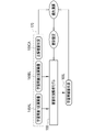
- the disaster information processing system 2 for grasping the damage situation of a disaster includes a surveillance camera 10 and a disaster information processing server 11.
- the surveillance camera 10 is installed on the roof of a high-rise building 12 of, for example, about 50 m to 100 m above the ground.
- the surveillance camera 10 is capable of swinging in the + direction (upward direction) and the minus direction (downward direction), that is, tilting operation.
- the surveillance camera 10 has a zoom lens, and it is possible to set a zoom magnification in a range from the same magnification (wide end) to, for example, 10 times (tele end).
- the disaster information processing server 11 is installed in, for example, a disaster countermeasures headquarters (agency, government office, etc.) of a local government such as a prefecture or a municipality.
- the disaster information processing server 11 is an example of the "disaster information processing device" according to the technique of the present disclosure.
- the surveillance camera 10 may be capable of swinging in the left-right direction, that is, panning.
- the surveillance camera 10 and the disaster information processing server 11 are connected to each other so as to be able to communicate with each other via the network 14.
- the surveillance camera 10 and the disaster information processing server 11 are connected to the network 14 by wire or wirelessly.
- the network 14 is a WAN (Wide Area Network) of, for example, the Internet or a public communication network.
- WAN Wide Area Network
- VPN Virtual Private Network
- HTTPS Hypertext Transfer Protocol
- the client terminal 15 is also connected to the network 14 by wire or wirelessly.
- the client terminal 15 is, for example, a desktop personal computer deployed to the staff of the disaster response headquarters, and has a display 16 and an input device 17. Various screens are displayed on the display 16.
- the input device 17 is a keyboard, a mouse, a touch panel, a microphone, or the like. Although only one client terminal 15 is drawn in FIG. 1, of course, there may be a plurality of client terminals 15.
- the surveillance camera 10 captures a shooting range 21 including a region 20 according to a preset frame rate (for example, 30 fps (frames per second)), and a bird's-eye view image 22 of the region 20. Is output.
- the shooting range 21 is a range determined based on the performance of the surveillance camera 10 when the zoom magnification is the same magnification (wide end) and the tilt angle is 0 ° (reference angle).
- the shooting range 21 is, for example, 4000 m in terms of the distance from the surveillance camera 10.
- the bottom side of the shooting range 21 (the lower side of the bird's-eye view image 22) is set to a distance of 0 m from the surveillance camera 10.
- the area 20 is an area where a disaster countermeasures headquarters is located due to a disaster, and is an example of a “disaster area” related to the technology of the present disclosure.
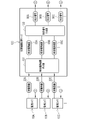
- the computer constituting the disaster information processing server 11 includes a storage 30, a memory 31, a CPU (Central Processing Unit) 32, and a communication unit 33. These are interconnected via a bus line 34.
- the storage 30 is an example of a “storage unit” according to the technique of the present disclosure.
- the CPU 32 is an example of a "processor” according to the technique of the present disclosure.
- the storage 30 is a hard disk drive built in the computer constituting the disaster information processing server 11 or connected via a cable or a network.
- the storage 30 is a disk array in which a plurality of hard disk drives are connected.
- the storage 30 stores control programs such as an operating system, various application programs, and various data associated with these programs.
- a solid state drive may be used instead of the hard disk drive.
- the memory 31 is a work memory for the CPU 32 to execute a process.
- the CPU 32 loads the program stored in the storage 30 into the memory 31 and executes the process according to the program. As a result, the CPU 32 comprehensively controls the operation of each part of the computer.
- the communication unit 33 controls transmission of various information with an external device such as a surveillance camera 10.
- the memory 31 may be built in the CPU 32.
- the operation program 40 is stored in the storage 30 of the disaster information processing server 11.
- the operation program 40 is an application program for making the computer function as the disaster information processing server 11. That is, the operation program 40 is an example of the "operation program of the disaster information processing apparatus" according to the technique of the present disclosure.
- the CPU 32 of the computer constituting the disaster information processing server 11 cooperates with the memory 31 and the like to read / write (hereinafter, abbreviated as RW (Read Write)) control unit 45 and effective visibility. It functions as a range derivation unit 46, a control signal generation unit 47, a transmission control unit 48, a damage status analysis unit 49, and a screen distribution control unit 50.
- RW Read Write
- the RW control unit 45 controls the storage of various data in the storage 30 and the reading of various data in the storage 30.
- the RW control unit 45 receives the bird's-eye view image 22 from the surveillance camera 10 and stores the received bird's-eye view image 22 in the storage 30.
- the RW control unit 45 receives the processing request (not shown) from the client terminal 15, the RW control unit 45 reads the bird's-eye view image 22 from the storage 30, and outputs the read bird's-eye view image 22 to the effective view range derivation unit 46.
- the RW control unit 45 When the RW control unit 45 receives the distribution request (not shown) from the client terminal 15, the RW control unit 45 reads the bird's-eye view image 22 from the storage 30 and outputs the read bird's-eye view image 22 to the damage status analysis unit 49.
- the storage of the bird's-eye view image 22 in the storage 30 is performed according to an instruction from the staff of the disaster countermeasures headquarters.
- the damage situation analysis unit 49 analyzes the disaster damage situation 69 (see FIG. 11) in the area 20 based on the bird's-eye view image 22.
- the damage status analysis unit 49 outputs the analysis result 57 of the damage status 69 to the screen distribution control unit 50.
- the screen distribution control unit 50 generates a damage status display screen 58 based on the analysis result 57.
- the screen distribution control unit 50 controls distribution of the screen data of the generated damage status display screen 58 to the client terminal 15 that is the request source of the distribution request.
- the screen data is screen data for web distribution created by a markup language such as XML (XML (Extensible Markup Language)).
- the client terminal 15 reproduces and displays the damage status display screen 58 on the web browser based on the screen data.
- XML XML (Extensible Markup Language)
- JSON Javascript (registered trademark) Object Notification
- the effective view range derivation unit 46 includes a building information addition unit 60, a building image cutout unit 61, a first processing unit 62, and an effective view range determination unit 63.
- the building information giving unit 60 assigns the building information 65 to each building 78 (see FIG. 7) reflected in the bird's-eye view image 22 with reference to the map 64 with the building information, and the bird's-eye view image 22 is the bird's-eye view image 22I with the building information.
- the building information adding unit 60 outputs the bird's-eye view image 22I with building information to the building image cutting unit 61.
- the map 64 with building information is stored in the storage 30, is read from the storage 30 by the RW control unit 45, and is output to the building information giving unit 60.
- the map 64 with building information is a three-dimensional map of the area 20, and the feature points such as the corners of the roof and the building information 65 are associated with each building 78.
- the building information 65 is specifically the name of the owner of the building (house) 78 such as "Fuji Kazuo" or the name of the building 78 such as "Fuji No. 1 Building". Further, the building information 65 also includes the distance of the building 78 from the surveillance camera 10, the address of the building 78, and the like.
- the building information adding unit 60 adjusts the direction of the building on the map 64 with building information to the direction of the building 78 shown in the bird's-eye view image 22 based on the latitude and longitude information of the installation position of the surveillance camera 10, the tilt angle, and the like. Further, the building information adding unit 60 extracts feature points such as corners of the roof of the building 78 reflected in the bird's-eye view image 22. The building information adding unit 60 matches the map 64 with building information and the bird's-eye view image 22 according to the orientation of the building 78 reflected in the bird's-eye view image 22, and the feature points of the map 64 with building information and the feature points of the bird's-eye view image 22. Search for the position where the correlation of is the highest. Then, at the position where the correlation is highest, the building information 65 of the map 64 with building information is given to each building 78 of the bird's-eye view image 22.
- the first processing unit 62 inputs the building image 66 into the damage situation analysis model 68. Then, the damage status 69 is output from the damage status analysis model 68.
- the damage situation 69 assumes an earthquake or the like as a disaster, and is one of "total destruction”, “half destruction”, “safety”, and "unknown”.
- the first processing unit 62 outputs the damage status 69 from the damage status analysis model 68 for all of the building images 66 of the five buildings 78 at a distance of 10 m from the surveillance camera 10 included in the building image group 67.
- the first processing unit 62 outputs the analysis result 70 for effective visibility range determination, which summarizes the damage status 69 for each building 78 together with the distance from the surveillance camera 10, to the effective visibility range determination unit 63.
- the effective view range determination unit 63 determines the effective view range 55 based on the analysis result 70 for determining the effective view range.
- the damage status 69 of the buildings 78 such as "Fuji Kazuo" and “Fuji Jiro” whose distance from the surveillance camera 10 is 0 m is "safe", and the distance from the surveillance camera 10 is 1300 m "Fuji No. 1".
- the case where the damage situation 69 such as "1 building” is "unknown” is illustrated.
- the effective field of view 55 is narrower than the shooting range 21 due to the influence of cloudiness, fog, rain, snow, smog, etc., and the effective field of view 55 is determined to be "1200 m" is illustrated.
- the effective visibility range determination unit 63 counts the number of buildings 78 whose damage status 69 is “unknown” for each distance from the surveillance camera 10. In the effective visibility range determination unit 63, among the distances from the surveillance camera 10, the number of buildings 78 whose damage status 69 is “unknown” is less than 5, and thereafter, the buildings whose damage status 69 is “unknown”. A distance in which the number of 78 houses is 5 and the distance is continuous two or more times is determined to be the effective viewing range 55.
- FIG. 7 illustrates a case where the effective viewing range 55 is determined to be “1200 m” as in the case of FIG.
- the control signal generation unit 47 is for photographing the effective view range 55 having a distance of 1200 m or less from the surveillance camera 10.
- a control signal 56 having a zoom magnification of 1 and a tilt angle of 0 ° is generated.
- the control signal generation unit 47 generates a control signal 56 having a zoom magnification of 10 times and a tilt angle of ⁇ 5 ° for shooting in a range of a distance of more than 1200 m from the surveillance camera 10.
- FIG. 9 shows a state in which the surveillance camera 10 captures a bird's-eye view image 22 of the area 20 based on the control signal 56 in which the zoom magnification is the same and the tilt angle is 0 °.
- the bird's-eye view image 22 shows all the buildings 78 in the shooting range 21, but since the effective view range 55 is 1200 m, it is possible to grasp the damage status of the buildings 78 in the range exceeding the effective view range 55. It is reflected in an impossible state.
- FIG. 10 shows how the surveillance camera 10 captures a bird's-eye view image 22 of the area 20 based on the control signal 56 having a zoom magnification of 10 times and a tilt angle of ⁇ 5 °.
- the shooting range 80 is narrower than that in the case of FIG. 9 and exceeds the effective field of view range 55 because the zoom magnification and the tilt angle are different. Therefore, in the bird's-eye view image 22 taken in this case, it is highly possible that the building 78 in the range exceeding the effective viewing range 55 is shown in a state where the damage situation can be grasped.
- the storage 30 stores both the bird's-eye view image 22 obtained in the case of FIG. 9 and the bird's-eye view image 22 obtained in the case of FIG. 10, and both bird's-eye view images 22 are output to the damage status analysis unit 49. To. Then, the analysis result 57 based on each of the two bird's-eye views images 22 is output.
- the damage situation analysis unit 49 has a building information adding unit 85, a building image cutting unit 86, and a second processing unit 87.
- the building information giving unit 85 like the building information giving unit 60 of the effective view range derivation unit 46, refers to the map 64 with building information and assigns the building information 65 to each building 78 shown in the bird's-eye view image 22.
- the building information adding unit 85 outputs the bird's-eye view image 22I with building information to the building image cutting unit 86.
- the building image cutting section 86 cuts out the building image 66 from the bird's-eye view image 22I with building information, like the building image cutting section 61 of the effective viewing range derivation section 46. However, the building image cutting unit 86 cuts out the building image 66 of all the buildings 78 reflected in the bird's-eye view image 22I with building information.
- the building image cutting unit 86 outputs a building image group 88 including a set of the building image 66 of all the buildings 78 and the building information 65 to the second processing unit 87.
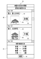
- the damage status display screen 58 displayed on the display 16 of the client terminal 15 has a damage status display area 90 for each building and a statistical damage status display area 91.
- the damage status display area 90 for each building the building information 65, the building image 66, and the damage status 69 of each building are displayed.
- the statistical damage status display area 91 the total number of buildings 78 completely destroyed, partially destroyed, safe, and unknown in the area 20 is displayed.
- the confirmation button 92 is selected, the display of the damage status display screen 58 is turned off.
- the CPU 32 of the disaster information processing server 11 has a RW control unit 45, an effective view range derivation unit 46, and a control signal generation unit. It functions as 47, a transmission control unit 48, a damage status analysis unit 49, and a screen distribution control unit 50.
- the effective view range derivation unit 46 includes a building information addition unit 60, a building image cutting unit 61, a first processing unit 62, and an effective view range determination unit 63.
- the damage situation analysis unit 49 includes a building information adding unit 85, a building image cutting unit 86, and a second processing unit 87.
- the bird's-eye view image 22 of the area 20 where the disaster occurred is transmitted from the surveillance camera 10 to the disaster information processing server 11.
- the bird's-eye view image 22 is accepted by the RW control unit 45 (step ST100).
- the bird's-eye view image 22 is stored in the storage 30 by the RW control unit 45 in response to an instruction from the staff of the disaster countermeasures headquarters.
- the bird's-eye view image 22 is read from the storage 30 by the RW control unit 45, and the read bird's-eye view image 22 is derived from the RW control unit 45 in the effective view range. It is output to the unit 46. Then, as shown in FIGS. 5 and 7, the effective view range deriving unit 46 derives the effective view range 55 in the bird's-eye view image 22 (step ST110). The effective view range 55 is output from the effective view range derivation unit 46 to the control signal generation unit 47.
- the control signal generation unit 47 generates the control signal 56 as shown in FIG. 8 based on the effective field of view 55 (step ST120).
- the control signal 56 is output from the control signal generation unit 47 to the transmission control unit 48. Then, the control signal 56 is transmitted to the surveillance camera 10 by the transmission control unit 48 (step ST130).
- the operation is controlled according to the control signal 56 as shown in FIGS. 9 and 10. Then, the bird's-eye view image 22 in the state shown in FIGS. 9 and 10 is stored in the storage 30 by the RW control unit 45 in response to an instruction from the staff of the disaster countermeasures headquarters.
- the bird's-eye view image 22 is read from the storage 30 by the RW control unit 45, and the read bird's-eye view image 22 is the RW control unit 45. Is output to the damage status analysis unit 49. Then, as shown in FIG. 11, the damage status analysis unit 49 analyzes the damage status 69 for each building 78 in the area 20 using the bird's-eye view image 22 (step ST200). The analysis result 57 of the damage status 69 is output from the damage status analysis unit 49 to the screen distribution control unit 50.
- the CPU 32 of the disaster information processing server 11 includes an effective view range derivation unit 46 and a control signal generation unit 47.
- the effective view range derivation unit 46 is the effective view range 55 in the bird's-eye view image 22 of the area 20 taken by the surveillance camera 10, and it is possible to grasp the damage situation 69 of the area 20 and according to the environmental conditions of the area 20. Obtained by deriving a changing effective field of view 55.
- the control signal generation unit 47 generates the control signal 56 of the surveillance camera 10 according to the effective field of view 55.
- the operation of the surveillance camera 10 is controlled by the control signal 56. Therefore, it is possible to control the operation of the surveillance camera 10 that matches the environmental conditions of the area 20.
- the control signal generation unit 47 generates a control signal 56 that sets the zoom magnification of the surveillance camera 10 and the tilt angle of the surveillance camera 10 based on the effective field of view range 55. Therefore, there is a high possibility that the building 78 whose damage status 69 is "unknown” under the default setting of the same magnification and the tilt angle of 0 ° can be captured in the bird's-eye view image 22 with relatively high image quality. The number of buildings 78 whose damage status 69 is "unknown” can be reduced.
- the effective view range derivation unit 46 derives the effective view range 55 from the bird's-eye view image 22 taken by the surveillance camera 10 in real time. Therefore, it is possible to acquire the effective viewing range 55 that is better suited to the current environmental conditions of the region 20, and it is possible to control the operation of the surveillance camera 10 that is better suited to the current environmental conditions of the region 20.
- the control signal 56 in which the shooting range 102 of the surveillance camera 10 is substantially the same as the effective view range 55 the range exceeding the effective view range 55 where the probability that the damage situation becomes “unknown” is very high is high.
- the building 78 is not shown in the bird's-eye view image 22. Therefore, it is possible to reduce the processing load of the damage status analysis unit 49 for the building 78 in the range exceeding the effective view range 55.
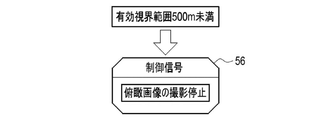
- the control signal 56 may have the content shown in FIG.
- the control signal 56 shown in FIG. 17 is a content that causes the surveillance camera 10 to stop taking a bird's-eye view image 22 when the effective viewing range 55 is less than a preset threshold value, for example, less than 500 m.
- the threshold value is set to a value at which even if the damage situation 69 is analyzed based on the bird's-eye view image 22 in the effective view range 55, there is not much merit as compared with the case where the damage situation is manually analyzed.
- control signal 56 that causes the surveillance camera 10 to stop taking a bird's-eye view image 22 when the effective viewing range 55 is less than the threshold value, it is possible to prevent the surveillance camera 10 from taking unnecessary pictures.
- the machine learning model used in the building image cutting unit 61 may be a model that outputs the evaluation value of the image quality of the building 78 reflected in the building image 66 in addition to the building image 66. Then, the effective viewing range 55 may be determined based on whether or not the building image 66 whose image quality evaluation value of the building 78 is equal to or higher than the preset threshold value can be cut out. Specifically, the distance before the distance where only the building image 66 whose image quality evaluation value of the building 78 is less than the threshold value can be cut out is determined to be the effective viewing range 55.
- the landmark building and its distance may be registered in advance, and the effective visibility range 55 may be determined based on the damage situation 69 for the building image 66 cut out from the landmark building.
- the effective view range deriving unit 46 derives the effective view range 55 from the bird's-eye view image 22 taken by the surveillance camera 10 in real time, but the present invention is not limited to this.
- the effective field of view 55 corresponding to the environmental conditions of a plurality of patterns may be stored in advance.
- the effective view range table 110 is stored in the storage 30 in advance.
- the effective view range table 110 is a table in which the effective view range 55 for each environmental condition is registered.
- Environmental conditions include “sunny (spring, summer)”, “sunny (autumn, winter)", “main cloudy”, “rain”, “snow”, “smog” and the like. Spring and summer are, for example, March to September, and autumn and winter are, for example, October to February.
- the effective view range 55 corresponding to the environmental conditions of the plurality of patterns is stored in the storage 30 in advance, and the RW control unit 45 is effective according to the current environmental conditions 111 of the region 20.
- the view range 55 is acquired by reading from the storage 30. Therefore, it is possible to save the trouble of deriving the effective view range 55 from the bird's-eye view image 22 as in the first embodiment.
- a plurality of surveillance cameras 10A, 10B, 10C, ... are connected to the disaster information processing server 120 of this embodiment.
- the disaster information processing server 120 receives the bird's-eye view image 22A from the surveillance camera 10A, the bird's-eye view image 22B from the surveillance camera 10B, the bird's-eye view image 22C from the surveillance camera 10C, and so on.
- the effective view range deriving unit 121 derives the effective view range 55A in the bird's-eye view image 22A, the effective view range 55B in the bird's-eye view image 22B, the effective view range 55C in the bird's-eye view image 22C, and so on.
- FIG. 20 shows a specific example of controlling the operation of each of the plurality of surveillance cameras 10.
- FIG. 20 shows an aspect of controlling the operation of each of the two surveillance cameras 10A and 10B for the sake of simplicity.
- the surveillance camera 10A is installed on the roof of the skyscraper 12A
- the surveillance camera 10B is installed on the roof of the skyscraper 12B facing the skyscraper 12A.
- the surveillance camera 10A initially captures the bird's-eye view image 22A of the default shooting range 21A based on the control signal 56A in which the zoom magnification is the same and the tilt angle is 0 °.
- the surveillance camera 10B captures a bird's-eye view image 22B having a default shooting range of 21B based on a control signal 56B having a zoom magnification of 1 and a tilt angle of 0 °.
- the control signal generation unit 122 generates a control signal 56A having the content of stopping the shooting of the bird's-eye view image 22A by the surveillance camera 10A. Further, the control signal generation unit 122 monitors the building 78 outside the effective view range 55B of the bird's-eye view image 22B by the surveillance camera 10B in order to capture the building 78 directly under the fire smoke 125 in the bird's-eye view image 22B. A control signal 56B having a zoom magnification of 10 times and a tilt angle of ⁇ 5 ° of the camera 10B is generated.
- the control signal generation unit 122 is each of the plurality of surveillance cameras 10 based on the effective viewing range 55 of each of the plurality of surveillance cameras 10.
- a control signal 56 for controlling the operation of the above is generated. Therefore, as shown in FIG. 20, a plurality of surveillance cameras 10 cooperate to capture a bird's-eye view image 22, such as covering a range that cannot be covered by one surveillance camera 10 with the other surveillance camera 10. be able to.
- each of the plurality of surveillance cameras 10 controls the operation of each of the plurality of surveillance cameras 10.
- the following can be considered in addition to the example shown in FIG.
- a control signal for stopping the shooting of the bird's-eye view image 22 by all the surveillance cameras 10. 56 is generated, and all the surveillance cameras 10 stop taking the bird's-eye view image 22.
- the damage situation 69 is analyzed based only on the bird's-eye view image 22 taken by one surveillance camera 10, but the damage situation is not limited to this.
- the damage situation may be analyzed based on the bird's-eye view images 22 taken by the plurality of surveillance cameras 10.
- a case where two surveillance cameras 10A and 10B are used as in the case of FIG. 20 will be illustrated. It is assumed that the shooting ranges of the surveillance cameras 10A and 10B overlap at least partially, and the same building 78 is captured in different modes in the bird's-eye view image 22A and the bird's-eye view image 22B.
- the building image cutting unit 132 cuts out the first building image 66A from the bird's-eye view image 22AI with building information, and cuts out the second building image 66B from the bird's-eye view image 22BI with building information.
- the building image cutting unit 132 includes a first building image group 88A including a plurality of pairs of the first building image 66A and the building information 65, and a second building image group including a plurality of pairs of the second building image 66B and the building information 65. 88B is output to the second processing unit 133.
- the loss calculation, the update setting, and the update of the damage situation analysis model 134 are repeatedly performed while the learning data 140 is exchanged.
- the repetition of the above series of processes ends when the discrimination accuracy of the learning damage situation 135L for the correct answer damage situation 135CA reaches a predetermined set level.
- the damage situation analysis model 134 whose discrimination accuracy has reached the set level is stored in the storage 30 and used by the second processing unit 133.
- the number of surveillance cameras 10 is not limited to two. Therefore, the building image 66 input to the damage situation analysis model 134 is also a building image 66 cut out from the bird's-eye view image 22 taken by three or more surveillance cameras 10. You may.
- the damage situation analysis unit 145 of the fifth embodiment has a section image cutting unit 146 and a second processing unit 147.
- the section image cutting section 146 cuts out the section image 149 for each section from the bird's-eye view image 22 with reference to the landmark building information 148.
- the section is a plurality of areas obtained by dividing the area 20, and is an area including a plurality of adjacent buildings 78 in the area 20.
- the sections are chome such as "Fuji 1-chome" and "Watabuki Kitsuneana 2-chome".
- the section image cutting unit 146 outputs a section image group 151 including a plurality of sets of the section image 149 and the section information 150 representing the section of the section image 149 to the second processing unit 147.
- the second processing unit 147 inputs the section image 149 into the damage situation analysis model 152. Then, the damage status 153 is output from the damage status analysis model 152. The damage status 153 is one of "large damage”, “small damage”, and "unknown”. The second processing unit 147 outputs the damage situation 153 from the damage situation analysis model 152 for all the section images 149 included in the section image group 151. The second processing unit 147 outputs an analysis result 154 that summarizes the damage status 153 for each section.
- FIG. 23 illustrates a case where the damage status 153 of the sections such as “Fuji 1-chome” and “Cotton fox hole 2-chome” is “damaged”.
- the damage situation analysis model 152 is a machine learning model constructed by methods such as a neural network, a support vector machine, and boosting, like the damage situation analysis models 68 and 134.
- the damage situation analysis model 152 is stored in the storage 30, is read from the storage 30 by the RW control unit 45, and is output to the second processing unit 147.
- the damage situation analysis model 152 is given the learning data 160 and is trained.
- the learning data 160 is a set of a learning section image 149L and a correct answer damage situation 153CA corresponding to the learning section image 149L.
- the learning section image 149L is obtained by inputting a bird's-eye view image of a certain area into the section image cutting unit 146.
- the correct answer damage situation 153CA is the result of actually determining the damage situation 153 of the section shown in the learning section image 149L by a qualified person such as a house damage certified person.
- the learning section image 149L is input to the damage situation analysis model 152.
- the damage situation analysis model 152 outputs the learning damage situation 153L to the learning section image 149L.
- the loss calculation of the damage situation analysis model 152 using the loss function is performed.
- various coefficients of the damage situation analysis model 152 are updated according to the result of the loss calculation, and the damage situation analysis model 152 is updated according to the update setting.
- the input of the learning section image 149L to the damage situation analysis model 152 the output of the learning damage situation 153L from the damage situation analysis model 152, the loss calculation, the update setting, and the damage situation.
- the above series of processes for updating the analysis model 152 are repeated while the training data 160 is exchanged. The repetition of the above series of processes ends when the discrimination accuracy of the learning damage situation 153L for the correct answer damage situation 153CA reaches a predetermined set level.
- the damage situation analysis model 152 whose discrimination accuracy has reached the set level is stored in the storage 30 and used by the second processing unit 147.
- the damage status analysis unit 145 analyzes the damage status 153 for each section including the plurality of adjacent buildings 78 in the area 20. Therefore, the analysis of the damage status 153 can be completed in a shorter time than the analysis of the damage status of the building 78 of each house. As a result, it is possible to quickly grasp the general damage situation 153, although it is a little rough.
- the damage situation analysis unit 165 when the damage situation analysis unit 165 has taken a picture of the section to be analyzed of the damage situation 169 with the plurality of surveillance cameras 10, the plurality of surveillance cameras 10 have taken pictures, respectively.
- the damage status 169 of the section to be analyzed is analyzed. Therefore, it is more likely that the damage situation 169 of the section, which is not clear only from the bird's-eye view image 22 taken by one surveillance camera 10, can be grasped, and as a result, the reliability of the analysis result 154 can be improved.
- the section including multiple adjacent buildings is not limited to the example chome.
- a rectangular area of a predetermined size may be defined as a section with the road as a boundary.
- any one of “large damage”, “small damage”, and “unknown” was exemplified, but the damage is not limited to this.
- any one of “total destruction”, “half destruction”, “safety”, and “unknown” may be used.
- the surveillance camera 10 is assumed to be a visible light camera, but the present invention is not limited to this.
- an infrared camera may be prepared for shooting in the evening and at night.
- the super-resolution technique using a machine learning model is applied to the bird's-eye view image 22 to make the bird's-eye view image 22 a super-resolution bird's-eye view image 22.
- the damage situation may be analyzed using the bird's-eye view image 22 of.
- the super-resolution bird's-eye view image 22 is a so-called fake image, it is preferable to clearly indicate that it is only for reference on the damage status display screen 58.
- RW control unit 45 effective field range derivation unit 46 and 121, control signal generation unit 47 and 122, transmission control unit 48, damage status analysis unit 49, 130, 145, and 165, screen distribution.
- Control unit 50 building information addition unit 60, 85, and 131, building image cutting unit 61, 86, and 132, first processing unit 62, second processing unit 87, 133, 147, and 167, and section image cutting unit.
- processing unit Processe.g., 146 and 166
- processors processors shown below can be used as the hardware structure of the processing unit (Processing Unit) that executes various processes such as 146 and 166.
- processors for various processors, as described above, in addition to the CPU 32, which is a general-purpose processor that executes software (operation program 40) and functions as various processing units, after manufacturing FPGA (Field Programmable Gate Array) and the like.
- Dedicated processor with a circuit configuration specially designed to execute specific processing such as programmable logic device (Programmable Logic Device: PLD), ASIC (Application Specific Integrated Circuit), which is a processor whose circuit configuration can be changed. Includes electrical circuits and the like.
- One processing unit may be composed of one of these various processors, or may be a combination of two or more processors of the same type or different types (for example, a combination of a plurality of FPGAs and / or a CPU). It may be configured in combination with FPGA). Further, a plurality of processing units may be configured by one processor.
- one processor is configured by a combination of one or more CPUs and software, as represented by a computer such as a client and a server.
- the processor functions as a plurality of processing units.
- SoC System On Chip
- SoC system On Chip
- the various processing units are configured by using one or more of the above-mentioned various processors as a hardware-like structure.
- an electric circuit in which circuit elements such as semiconductor elements are combined can be used.
- a and / or B is synonymous with "at least one of A and B". That is, “A and / or B” means that it may be A alone, B alone, or a combination of A and B. Further, in the present specification, when three or more matters are connected and expressed by "and / or", the same concept as “A and / or B" is applied.
Landscapes
- Engineering & Computer Science (AREA)
- Multimedia (AREA)
- Signal Processing (AREA)
- Physics & Mathematics (AREA)
- General Physics & Mathematics (AREA)
- Theoretical Computer Science (AREA)
- Computer Vision & Pattern Recognition (AREA)
- Quality & Reliability (AREA)
- Environmental & Geological Engineering (AREA)
- Emergency Management (AREA)
- Business, Economics & Management (AREA)
- Geology (AREA)
- General Life Sciences & Earth Sciences (AREA)
- Life Sciences & Earth Sciences (AREA)
- Alarm Systems (AREA)
- Closed-Circuit Television Systems (AREA)
- Studio Devices (AREA)
Priority Applications (2)
| Application Number | Priority Date | Filing Date | Title |
|---|---|---|---|
| JP2022553831A JP7715726B2 (ja) | 2020-10-01 | 2021-09-17 | 災害情報処理装置、災害情報処理装置の作動方法、災害情報処理装置の作動プログラム、並びに災害情報処理システム |
| US18/188,944 US12531964B2 (en) | 2020-10-01 | 2023-03-23 | Disaster information processing apparatus, operation method of disaster information processing apparatus, operation program of disaster information processing apparatus, and disaster information processing system |
Applications Claiming Priority (2)
| Application Number | Priority Date | Filing Date | Title |
|---|---|---|---|
| JP2020-167013 | 2020-10-01 | ||
| JP2020167013 | 2020-10-01 |
Related Child Applications (1)
| Application Number | Title | Priority Date | Filing Date |
|---|---|---|---|
| US18/188,944 Continuation US12531964B2 (en) | 2020-10-01 | 2023-03-23 | Disaster information processing apparatus, operation method of disaster information processing apparatus, operation program of disaster information processing apparatus, and disaster information processing system |
Publications (1)
| Publication Number | Publication Date |
|---|---|
| WO2022070981A1 true WO2022070981A1 (ja) | 2022-04-07 |
Family
ID=80951467
Family Applications (1)
| Application Number | Title | Priority Date | Filing Date |
|---|---|---|---|
| PCT/JP2021/034263 Ceased WO2022070981A1 (ja) | 2020-10-01 | 2021-09-17 | 災害情報処理装置、災害情報処理装置の作動方法、災害情報処理装置の作動プログラム、並びに災害情報処理システム |
Country Status (3)
| Country | Link |
|---|---|
| US (1) | US12531964B2 (https=) |
| JP (1) | JP7715726B2 (https=) |
| WO (1) | WO2022070981A1 (https=) |
Cited By (1)
| Publication number | Priority date | Publication date | Assignee | Title |
|---|---|---|---|---|
| CN114722113A (zh) * | 2022-06-10 | 2022-07-08 | 中国地质科学院地质力学研究所 | 一种用于地质灾害的数据可视化处理方法及系统 |
Citations (2)
| Publication number | Priority date | Publication date | Assignee | Title |
|---|---|---|---|---|
| JP2006165981A (ja) * | 2004-12-07 | 2006-06-22 | Hitachi Kokusai Electric Inc | 無線通信システム |
| JP2020017102A (ja) * | 2018-07-26 | 2020-01-30 | 株式会社シー・イー・デー・システム | 火災監視装置、および火災監視システム |
Family Cites Families (9)
| Publication number | Priority date | Publication date | Assignee | Title |
|---|---|---|---|---|
| JP5966456B2 (ja) | 2012-03-08 | 2016-08-10 | オムロン株式会社 | アダプタ |
| US10134092B1 (en) * | 2014-10-09 | 2018-11-20 | State Farm Mutual Automobile Insurance Company | Method and system for assessing damage to insured properties in a neighborhood |
| US9129355B1 (en) * | 2014-10-09 | 2015-09-08 | State Farm Mutual Automobile Insurance Company | Method and system for assessing damage to infrastructure |
| KR20170101519A (ko) * | 2016-02-29 | 2017-09-06 | 한국전자통신연구원 | 무인 항공기를 이용한 재난 감시 장치 및 방법 |
| US9846915B2 (en) * | 2016-03-17 | 2017-12-19 | Conduent Business Services, Llc | Image capture system for property damage assessment |
| WO2018058044A1 (en) * | 2016-09-23 | 2018-03-29 | Aon Benfield Inc. | Platform, systems, and methods for identifying property characteristics and property feature maintenance through aerial imagery analysis |
| JP7629021B2 (ja) * | 2020-09-23 | 2025-02-12 | 富士フイルム株式会社 | 被害判定情報システム、サーバ装置およびプログラム |
| WO2022070808A1 (ja) * | 2020-10-01 | 2022-04-07 | 富士フイルム株式会社 | 災害情報処理装置、災害情報処理装置の作動方法、災害情報処理装置の作動プログラム、並びに災害情報処理システム |
| JP7756149B2 (ja) * | 2021-03-19 | 2025-10-17 | 富士フイルム株式会社 | 被災情報処理装置、被災情報処理システム、被災情報処理方法及びプログラム |
-
2021
- 2021-09-17 WO PCT/JP2021/034263 patent/WO2022070981A1/ja not_active Ceased
- 2021-09-17 JP JP2022553831A patent/JP7715726B2/ja active Active
-
2023
- 2023-03-23 US US18/188,944 patent/US12531964B2/en active Active
Patent Citations (2)
| Publication number | Priority date | Publication date | Assignee | Title |
|---|---|---|---|---|
| JP2006165981A (ja) * | 2004-12-07 | 2006-06-22 | Hitachi Kokusai Electric Inc | 無線通信システム |
| JP2020017102A (ja) * | 2018-07-26 | 2020-01-30 | 株式会社シー・イー・デー・システム | 火災監視装置、および火災監視システム |
Cited By (2)
| Publication number | Priority date | Publication date | Assignee | Title |
|---|---|---|---|---|
| CN114722113A (zh) * | 2022-06-10 | 2022-07-08 | 中国地质科学院地质力学研究所 | 一种用于地质灾害的数据可视化处理方法及系统 |
| CN114722113B (zh) * | 2022-06-10 | 2022-08-09 | 中国地质科学院地质力学研究所 | 一种用于地质灾害的数据可视化处理方法及系统 |
Also Published As
| Publication number | Publication date |
|---|---|
| US20230231975A1 (en) | 2023-07-20 |
| US12531964B2 (en) | 2026-01-20 |
| JPWO2022070981A1 (https=) | 2022-04-07 |
| JP7715726B2 (ja) | 2025-07-30 |
Similar Documents
| Publication | Publication Date | Title |
|---|---|---|
| US12423756B2 (en) | Method and system for remote virtual visualization of physical locations | |
| US11676258B1 (en) | Method and system for assessing damage to infrastructure | |
| US10565659B1 (en) | Method and system for generating real-time images of customer homes during a catastrophe | |
| US11893538B1 (en) | Intelligent system and method for assessing structural damage using aerial imagery | |
| US10134092B1 (en) | Method and system for assessing damage to insured properties in a neighborhood | |
| WO2021253961A1 (zh) | 一种智能视觉感知系统 | |
| US9875509B1 (en) | Method and system for determining the condition of insured properties in a neighborhood | |
| WO2021095351A1 (ja) | 監視装置、監視方法、及びプログラム | |
| JP7505609B2 (ja) | 光ファイバセンシングシステム及び行動特定方法 | |
| US11434005B1 (en) | Indoor drone flight awareness system | |
| US12207021B2 (en) | Disaster information processing apparatus, operation method of disaster information processing apparatus, operation program of disaster information processing apparatus, and disaster information processing system | |
| JPWO2020174634A1 (ja) | デジタルアキュレート・セキュリティシステム、方法及びプログラム | |
| CN104966375A (zh) | 一种安防监控系统及监控方法 | |
| Kustu et al. | Deep learning and stereo vision based detection of post-earthquake fire geolocation for smart cities within the scope of disaster management: İstanbul case | |
| WO2022078182A1 (zh) | 抛出位置获取方法、装置、计算机设备及存储介质 | |
| CN108638082A (zh) | 基于物联网的安防机器人系统 | |
| KR20220072783A (ko) | Cctv 영상을 이용한 실시간 침수 감지 시스템, 감시 시스템, 방법, 및 상기 방법을 실행시키기 위한 컴퓨터 판독 가능한 프로그램을 기록한 기록 매체 | |
| WO2022070956A1 (ja) | 情報処理装置、情報処理方法、プログラム、及び情報収集システム | |
| US12531964B2 (en) | Disaster information processing apparatus, operation method of disaster information processing apparatus, operation program of disaster information processing apparatus, and disaster information processing system | |
| KR102633938B1 (ko) | Cctv 영상을 활용한 군중 밀집도 계산 방법 및 장치 | |
| US12118779B1 (en) | System and method for assessing structural damage in occluded aerial images | |
| WO2021199306A1 (ja) | 通信量制御装置、通信量制御方法、及び、プログラムが記録された記録媒体 | |
| CN112924040A (zh) | 热感摄像机运行状况监控 | |
| JP7756149B2 (ja) | 被災情報処理装置、被災情報処理システム、被災情報処理方法及びプログラム | |
| CN113723700A (zh) | 森林火灾监测预测系统 |
Legal Events
| Date | Code | Title | Description |
|---|---|---|---|
| 121 | Ep: the epo has been informed by wipo that ep was designated in this application |
Ref document number: 21875283 Country of ref document: EP Kind code of ref document: A1 |
|
| ENP | Entry into the national phase |
Ref document number: 2022553831 Country of ref document: JP Kind code of ref document: A |
|
| NENP | Non-entry into the national phase |
Ref country code: DE |
|
| 122 | Ep: pct application non-entry in european phase |
Ref document number: 21875283 Country of ref document: EP Kind code of ref document: A1 |