WO2022070972A1 - 蓄電モジュール - Google Patents
蓄電モジュール Download PDFInfo
- Publication number
- WO2022070972A1 WO2022070972A1 PCT/JP2021/034223 JP2021034223W WO2022070972A1 WO 2022070972 A1 WO2022070972 A1 WO 2022070972A1 JP 2021034223 W JP2021034223 W JP 2021034223W WO 2022070972 A1 WO2022070972 A1 WO 2022070972A1
- Authority
- WO
- WIPO (PCT)
- Prior art keywords
- power storage
- storage device
- negative electrode
- storage module
- lead
- Prior art date
Links
- 238000007789 sealing Methods 0.000 description 17
- 230000002093 peripheral effect Effects 0.000 description 7
- 230000000630 rising effect Effects 0.000 description 6
- 239000011888 foil Substances 0.000 description 5
- 238000009751 slip forming Methods 0.000 description 5
- 229910052751 metal Inorganic materials 0.000 description 3
- 239000002184 metal Substances 0.000 description 3
- HBBGRARXTFLTSG-UHFFFAOYSA-N Lithium ion Chemical compound [Li+] HBBGRARXTFLTSG-UHFFFAOYSA-N 0.000 description 2
- PXHVJJICTQNCMI-UHFFFAOYSA-N Nickel Chemical compound [Ni] PXHVJJICTQNCMI-UHFFFAOYSA-N 0.000 description 2
- 229910001416 lithium ion Inorganic materials 0.000 description 2
- -1 polyethylene Polymers 0.000 description 2
- 229920005992 thermoplastic resin Polymers 0.000 description 2
- UFHFLCQGNIYNRP-UHFFFAOYSA-N Hydrogen Chemical compound [H][H] UFHFLCQGNIYNRP-UHFFFAOYSA-N 0.000 description 1
- 239000004952 Polyamide Substances 0.000 description 1
- 239000004698 Polyethylene Substances 0.000 description 1
- 239000004743 Polypropylene Substances 0.000 description 1
- 229920000122 acrylonitrile butadiene styrene Polymers 0.000 description 1
- 239000004676 acrylonitrile butadiene styrene Substances 0.000 description 1
- 239000003990 capacitor Substances 0.000 description 1
- 230000005611 electricity Effects 0.000 description 1
- 239000008151 electrolyte solution Substances 0.000 description 1
- 229920006351 engineering plastic Polymers 0.000 description 1
- 238000005530 etching Methods 0.000 description 1
- 229910052739 hydrogen Inorganic materials 0.000 description 1
- 239000001257 hydrogen Substances 0.000 description 1
- 238000009413 insulation Methods 0.000 description 1
- 239000000463 material Substances 0.000 description 1
- 239000007769 metal material Substances 0.000 description 1
- 230000004048 modification Effects 0.000 description 1
- 238000012986 modification Methods 0.000 description 1
- 229910052759 nickel Inorganic materials 0.000 description 1
- 239000004033 plastic Substances 0.000 description 1
- 229920003023 plastic Polymers 0.000 description 1
- 229920002647 polyamide Polymers 0.000 description 1
- 229920000573 polyethylene Polymers 0.000 description 1
- 229920001155 polypropylene Polymers 0.000 description 1
Images


Classifications
-
- H—ELECTRICITY
- H01—ELECTRIC ELEMENTS
- H01G—CAPACITORS; CAPACITORS, RECTIFIERS, DETECTORS, SWITCHING DEVICES OR LIGHT-SENSITIVE DEVICES, OF THE ELECTROLYTIC TYPE
- H01G11/00—Hybrid capacitors, i.e. capacitors having different positive and negative electrodes; Electric double-layer [EDL] capacitors; Processes for the manufacture thereof or of parts thereof
- H01G11/74—Terminals, e.g. extensions of current collectors
- H01G11/76—Terminals, e.g. extensions of current collectors specially adapted for integration in multiple or stacked hybrid or EDL capacitors
-
- H—ELECTRICITY
- H01—ELECTRIC ELEMENTS
- H01M—PROCESSES OR MEANS, e.g. BATTERIES, FOR THE DIRECT CONVERSION OF CHEMICAL ENERGY INTO ELECTRICAL ENERGY
- H01M50/00—Constructional details or processes of manufacture of the non-active parts of electrochemical cells other than fuel cells, e.g. hybrid cells
- H01M50/50—Current conducting connections for cells or batteries
- H01M50/502—Interconnectors for connecting terminals of adjacent batteries; Interconnectors for connecting cells outside a battery casing
- H01M50/503—Interconnectors for connecting terminals of adjacent batteries; Interconnectors for connecting cells outside a battery casing characterised by the shape of the interconnectors
-
- H—ELECTRICITY
- H01—ELECTRIC ELEMENTS
- H01G—CAPACITORS; CAPACITORS, RECTIFIERS, DETECTORS, SWITCHING DEVICES OR LIGHT-SENSITIVE DEVICES, OF THE ELECTROLYTIC TYPE
- H01G11/00—Hybrid capacitors, i.e. capacitors having different positive and negative electrodes; Electric double-layer [EDL] capacitors; Processes for the manufacture thereof or of parts thereof
- H01G11/10—Multiple hybrid or EDL capacitors, e.g. arrays or modules
-
- H—ELECTRICITY
- H01—ELECTRIC ELEMENTS
- H01G—CAPACITORS; CAPACITORS, RECTIFIERS, DETECTORS, SWITCHING DEVICES OR LIGHT-SENSITIVE DEVICES, OF THE ELECTROLYTIC TYPE
- H01G11/00—Hybrid capacitors, i.e. capacitors having different positive and negative electrodes; Electric double-layer [EDL] capacitors; Processes for the manufacture thereof or of parts thereof
- H01G11/78—Cases; Housings; Encapsulations; Mountings
- H01G11/82—Fixing or assembling a capacitive element in a housing, e.g. mounting electrodes, current collectors or terminals in containers or encapsulations
-
- H—ELECTRICITY
- H01—ELECTRIC ELEMENTS
- H01M—PROCESSES OR MEANS, e.g. BATTERIES, FOR THE DIRECT CONVERSION OF CHEMICAL ENERGY INTO ELECTRICAL ENERGY
- H01M50/00—Constructional details or processes of manufacture of the non-active parts of electrochemical cells other than fuel cells, e.g. hybrid cells
- H01M50/20—Mountings; Secondary casings or frames; Racks, modules or packs; Suspension devices; Shock absorbers; Transport or carrying devices; Holders
- H01M50/204—Racks, modules or packs for multiple batteries or multiple cells
- H01M50/207—Racks, modules or packs for multiple batteries or multiple cells characterised by their shape
- H01M50/213—Racks, modules or packs for multiple batteries or multiple cells characterised by their shape adapted for cells having curved cross-section, e.g. round or elliptic
-
- H—ELECTRICITY
- H01—ELECTRIC ELEMENTS
- H01M—PROCESSES OR MEANS, e.g. BATTERIES, FOR THE DIRECT CONVERSION OF CHEMICAL ENERGY INTO ELECTRICAL ENERGY
- H01M50/00—Constructional details or processes of manufacture of the non-active parts of electrochemical cells other than fuel cells, e.g. hybrid cells
- H01M50/20—Mountings; Secondary casings or frames; Racks, modules or packs; Suspension devices; Shock absorbers; Transport or carrying devices; Holders
- H01M50/296—Mountings; Secondary casings or frames; Racks, modules or packs; Suspension devices; Shock absorbers; Transport or carrying devices; Holders characterised by terminals of battery packs
-
- H—ELECTRICITY
- H01—ELECTRIC ELEMENTS
- H01M—PROCESSES OR MEANS, e.g. BATTERIES, FOR THE DIRECT CONVERSION OF CHEMICAL ENERGY INTO ELECTRICAL ENERGY
- H01M50/00—Constructional details or processes of manufacture of the non-active parts of electrochemical cells other than fuel cells, e.g. hybrid cells
- H01M50/20—Mountings; Secondary casings or frames; Racks, modules or packs; Suspension devices; Shock absorbers; Transport or carrying devices; Holders
- H01M50/298—Mountings; Secondary casings or frames; Racks, modules or packs; Suspension devices; Shock absorbers; Transport or carrying devices; Holders characterised by the wiring of battery packs
-
- H—ELECTRICITY
- H01—ELECTRIC ELEMENTS
- H01M—PROCESSES OR MEANS, e.g. BATTERIES, FOR THE DIRECT CONVERSION OF CHEMICAL ENERGY INTO ELECTRICAL ENERGY
- H01M50/00—Constructional details or processes of manufacture of the non-active parts of electrochemical cells other than fuel cells, e.g. hybrid cells
- H01M50/50—Current conducting connections for cells or batteries
- H01M50/502—Interconnectors for connecting terminals of adjacent batteries; Interconnectors for connecting cells outside a battery casing
- H01M50/514—Methods for interconnecting adjacent batteries or cells
- H01M50/516—Methods for interconnecting adjacent batteries or cells by welding, soldering or brazing
-
- H—ELECTRICITY
- H01—ELECTRIC ELEMENTS
- H01M—PROCESSES OR MEANS, e.g. BATTERIES, FOR THE DIRECT CONVERSION OF CHEMICAL ENERGY INTO ELECTRICAL ENERGY
- H01M50/00—Constructional details or processes of manufacture of the non-active parts of electrochemical cells other than fuel cells, e.g. hybrid cells
- H01M50/50—Current conducting connections for cells or batteries
- H01M50/543—Terminals
- H01M50/547—Terminals characterised by the disposition of the terminals on the cells
- H01M50/548—Terminals characterised by the disposition of the terminals on the cells on opposite sides of the cell
-
- H—ELECTRICITY
- H01—ELECTRIC ELEMENTS
- H01M—PROCESSES OR MEANS, e.g. BATTERIES, FOR THE DIRECT CONVERSION OF CHEMICAL ENERGY INTO ELECTRICAL ENERGY
- H01M50/00—Constructional details or processes of manufacture of the non-active parts of electrochemical cells other than fuel cells, e.g. hybrid cells
- H01M50/50—Current conducting connections for cells or batteries
- H01M50/543—Terminals
- H01M50/547—Terminals characterised by the disposition of the terminals on the cells
- H01M50/55—Terminals characterised by the disposition of the terminals on the cells on the same side of the cell
-
- H—ELECTRICITY
- H01—ELECTRIC ELEMENTS
- H01M—PROCESSES OR MEANS, e.g. BATTERIES, FOR THE DIRECT CONVERSION OF CHEMICAL ENERGY INTO ELECTRICAL ENERGY
- H01M50/00—Constructional details or processes of manufacture of the non-active parts of electrochemical cells other than fuel cells, e.g. hybrid cells
- H01M50/50—Current conducting connections for cells or batteries
- H01M50/543—Terminals
- H01M50/552—Terminals characterised by their shape
- H01M50/553—Terminals adapted for prismatic, pouch or rectangular cells
-
- H—ELECTRICITY
- H01—ELECTRIC ELEMENTS
- H01M—PROCESSES OR MEANS, e.g. BATTERIES, FOR THE DIRECT CONVERSION OF CHEMICAL ENERGY INTO ELECTRICAL ENERGY
- H01M50/00—Constructional details or processes of manufacture of the non-active parts of electrochemical cells other than fuel cells, e.g. hybrid cells
- H01M50/50—Current conducting connections for cells or batteries
- H01M50/543—Terminals
- H01M50/552—Terminals characterised by their shape
- H01M50/559—Terminals adapted for cells having curved cross-section, e.g. round, elliptic or button cells
-
- H—ELECTRICITY
- H01—ELECTRIC ELEMENTS
- H01G—CAPACITORS; CAPACITORS, RECTIFIERS, DETECTORS, SWITCHING DEVICES OR LIGHT-SENSITIVE DEVICES, OF THE ELECTROLYTIC TYPE
- H01G11/00—Hybrid capacitors, i.e. capacitors having different positive and negative electrodes; Electric double-layer [EDL] capacitors; Processes for the manufacture thereof or of parts thereof
- H01G11/74—Terminals, e.g. extensions of current collectors
-
- H—ELECTRICITY
- H01—ELECTRIC ELEMENTS
- H01M—PROCESSES OR MEANS, e.g. BATTERIES, FOR THE DIRECT CONVERSION OF CHEMICAL ENERGY INTO ELECTRICAL ENERGY
- H01M2220/00—Batteries for particular applications
- H01M2220/20—Batteries in motive systems, e.g. vehicle, ship, plane
-
- Y—GENERAL TAGGING OF NEW TECHNOLOGICAL DEVELOPMENTS; GENERAL TAGGING OF CROSS-SECTIONAL TECHNOLOGIES SPANNING OVER SEVERAL SECTIONS OF THE IPC; TECHNICAL SUBJECTS COVERED BY FORMER USPC CROSS-REFERENCE ART COLLECTIONS [XRACs] AND DIGESTS
- Y02—TECHNOLOGIES OR APPLICATIONS FOR MITIGATION OR ADAPTATION AGAINST CLIMATE CHANGE
- Y02E—REDUCTION OF GREENHOUSE GAS [GHG] EMISSIONS, RELATED TO ENERGY GENERATION, TRANSMISSION OR DISTRIBUTION
- Y02E60/00—Enabling technologies; Technologies with a potential or indirect contribution to GHG emissions mitigation
- Y02E60/10—Energy storage using batteries
Definitions
- This disclosure relates to a power storage module.
- a power storage module is known as a power source provided with a plurality of power storage devices.
- the power storage module disclosed in Patent Document 1 includes a plurality of cylindrical batteries.
- the sealing body is configured as a positive electrode terminal and the outer can is configured as a negative electrode terminal, and the negative electrode lead is bonded to the shoulder portion (crimped open end portion) of the outer can.
- An object of the present disclosure is to provide a power storage module capable of aligning the position of a lead with an appropriate joining position in an outer can with high accuracy, such as the above-mentioned negative electrode lead.
- the power storage module includes at least one cylindrical power storage device, and a first terminal and a second terminal are arranged at one end of the power storage device, and a second terminal is arranged. Further comprises a lead located outside the first terminal in the radial direction of the power storage device and electrically connected to the second terminal from the outside in the radial direction, and the lead is in contact with the side surface of the power storage device. It has a contact portion and a shoulder portion formed inside the contact portion in the radial direction and including a joint portion with a second terminal.
- the position of the lead can be adjusted with high accuracy to the proper joining position at the second terminal. This makes it possible to reduce the mounting tolerance between the second terminal and the lead.
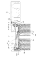
- FIG. 1 is a side sectional view showing a power storage module 10.
- the side of the power storage module 10 and the power storage device 20 where the upper holder 40 as a holder holds the power storage device 20 will be described as the upper side in the vertical direction.
- the upper holder 40 may be on the lower side of the power storage module 10.
- the power storage module 10 is mainly used as a power source for power.
- the power storage module 10 is used as a power source for electric devices driven by motors such as electric vehicles, electric tools, electric assisted bicycles, electric bikes, electric wheelchairs, electric three-wheeled vehicles, and electric carts.
- motors such as electric vehicles, electric tools, electric assisted bicycles, electric bikes, electric wheelchairs, electric three-wheeled vehicles, and electric carts.
- the use of the power storage module 10 is not limited, and may be used as a power source for various electric devices used indoors and outdoors, such as cleaners, radios, lighting devices, digital cameras, and video cameras.
- the power storage module 10 includes a plurality of cylindrical power storage devices 20, a power collection member 30 that collects electricity from a first terminal (positive electrode terminal) and a second terminal (negative electrode terminal) of the power storage device 20. It includes an upper holder 40 as a holder for holding the upper end side of each of the plurality of power storage devices 20, and a lower holder 50 for holding each of the lower end sides of the plurality of power storage devices 20. Details of the current collector member 30 and the upper holder 40 will be described later.
- FIG. 2 is a plan view showing the current collector member 30.
- the current collector member 30 is formed of a plate-shaped metal material (metal foil) and is provided on the top surface of the upper holder 40.
- the current collector member 30 includes a positive electrode lead 31 connected to the positive electrode terminal of the power storage device 20, a connecting portion 32 connecting the positive electrode leads 31 to each other, and a negative electrode lead 60 as a lead connected to the negative electrode terminal of the power storage device 20. It is formed.
- the negative electrode lead 60 includes a fuse portion 65 that connects the negative electrode lead 60 and the connecting portion 32. The details of the negative electrode lead 60 will be described later.
- the positive electrode lead 31 extends above the opening 42 of the upper holder 40 described later and is joined to the top surface of the sealing body 26 as the positive electrode terminal described later.
- the connecting portion 32 is formed in a band shape or a sheet shape.
- the negative electrode lead 60 extends above the notch 43 of the upper holder 40 described later and is joined to the shoulder portion 25C of the outer can 25 as the negative electrode terminal described later.
- the fuse portion 65 is formed in a band shape narrower than the connecting portion 32, and is provided so as not to overlap the opening portion 42 and the notch portion 43 of the upper holder 40. In the power storage device of the present disclosure, the fuse unit 65 may not be provided.
- the functions of connecting the positive electrode terminal and the negative electrode terminal of the power storage device 20 and collecting power of the plurality of power storage devices 20 are realized by one metal foil, so that the current collection loss is achieved. Can be kept small. Further, according to the current collector member 30, since it is formed of one metal foil, it can be processed with high accuracy and low cost by etching or the like.
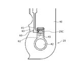
- FIG. 3 is a detailed view of part A in FIG.
- each member will be described according to the radial direction and the circumferential direction of the cylindrical shape of the power storage device 20.
- the power storage device 20 a cylindrical lithium ion secondary battery is used.
- the power storage device 20 is not limited to the lithium ion secondary battery, and may be a nickel hydrogen battery, a capacitor, or the like.
- a positive electrode terminal as a first terminal and a negative electrode terminal as a second terminal are arranged at the upper end portion.
- the negative electrode terminal is arranged radially outside the positive electrode terminal.
- the positive electrode terminal is configured on the top surface of the sealing body 26 described later.
- the negative electrode terminal is configured at the crimped open end portion (hereinafter, shoulder portion 25C) of the outer can 25 described later.
- the power storage device 20 includes, for example, an electrode group 24 in which a band-shaped positive electrode 21 and a band-shaped negative electrode 22 are wound via a band-shaped separator 23, and a cylindrical outer can 25 containing the electrode group 24 together with an electrolytic solution.
- the sealing body 26 that seals the opening of the outer can 25 in an insulated state
- the foil-shaped positive electrode tab 27 that electrically connects the positive electrode 21 and the sealing body 26, and the negative electrode 22 and the outer can 25 are electrically connected. It has a negative electrode tab (not shown) to connect to.
- An insulating gasket 28 is arranged between the outer periphery of the sealing body 26 and the inner peripheral surface of the opening of the outer can 25.
- the positive electrode tab 27 may be connected to the outer can 25, and the negative electrode tab may be connected to the sealing body 26.
- the second terminal becomes a positive electrode terminal.
- the lead used as the negative electrode lead 60 is used as the lead of the positive electrode.
- An annular groove 25A is formed on the opening side of the outer peripheral surface of the outer can 25.
- an annular convex portion 25B is formed on the inner peripheral surface of the corresponding outer can 25.
- the gasket 28 and the sealing body 26 are arranged on the annular convex portion 25B in the outer can 25.
- the shoulder portion 25C of the outer can 25 is crimped so as to fall toward the inside of the outer can 25 with the gasket 28 arranged on the inner peripheral side.
- the opening of the outer can 25 is sealed by the sealing body 26 being vertically sandwiched by the crimped shoulder portion 25C and the convex portion 25B via the gasket 28.
- the shoulder portion 25C is not limited to the above-mentioned configuration.
- it has a terminal plate at the center of the sealing body 26 and a conductive joint portion arranged on the outermost periphery of the sealing body 26 in a state of being insulated from the terminal plate, and the opening end portion and this joint portion are welded together. By doing so, the opening of the outer can 25 may be sealed. At this time, the negative electrode lead 60 may be connected to the top surface of the joint portion.
- the sealing body 26 may be provided with a current cutoff mechanism (CID) or an exhaust valve that bursts when the inside of the outer can 25 reaches a predetermined pressure or higher.
- a current cutoff mechanism CID
- an insulating plate 29 for insulating the electrode group 24 and the outer can 25 may be provided between the electrode group 24 and the convex portion 25B.
- the positive electrode tab 27 may extend through a through hole formed in the insulating plate 29.
- an insulating plate for insulating the electrode group 24 and the outer can 25 may be provided between the electrode group 24 and the bottom of the outer can 25.
- the negative electrode tab may pass through a through hole formed in the insulating plate or may extend by bypassing the insulating plate.
- the positive electrode terminal is configured on the top surface of the sealing body 26, and the positive electrode lead 31 (see FIG. 2) connected to the positive electrode current collector foil is joined.
- the negative electrode terminal is configured on the crimped shoulder portion 25C of the outer can 25, and the negative electrode tab connected to the negative electrode current collecting foil is joined to the bottom portion of the outer can 25.
- the negative electrode lead 60 is joined to the shoulder portion 25C of the outer can 25 from the radial outside of the power storage device 20.
- the upper holder 40 according to the embodiment will be described with reference to FIG.
- the upper holder 40 is a member that holds the upper end side of the plurality of power storage devices 20.
- the upper holder 40 is formed of a thermoplastic resin.
- the thermoplastic resin is roughly classified into general-purpose plastics and engineering plastics, and polyethylene, polypropylene, polyamide, ABS and the like are used.
- FIG. 3 a plurality of accommodating portions 41 in which the upper end side of each power storage device 20 is accommodated are formed on the bottom surface of the upper holder 40. By fitting the upper end side of the power storage device 20 into the accommodating portion 41, the upper end side of the power storage device 20 is held by the upper holder 40.
- the accommodating portion 41 is a bottom surface of the upper holder 40 as a recess including a ceiling portion 41A having a bottom surface facing the upper end surface of the power storage device 20 and a wall portion 41B having an inner peripheral surface facing the side peripheral surface of the power storage device 20. Is formed in.
- a notch 43 to be exposed is formed.
- the opening 42 is a portion in which the ceiling portion 41A of the accommodating portion 41 is opened in a circular shape.
- the diameter of the opening 42 is formed to be smaller than the inner diameter of the wall 41B. According to the opening 42, the top surface of the sealing body 26 of the power storage device 20 is exposed from the upper surface of the upper holder 40. Therefore, the top surface of the sealing body 26 and the positive electrode lead 31 can be joined via the opening 42. Further, the bottom portion of the ceiling portion 41A may be in contact with the power storage device 20.
- the cutout portion 43 is a portion formed by cutting out a part of the edge portion of the opening portion 42. According to the cutout portion 43, a part of the shoulder portion 25C of the outer can 25 of the power storage device 20 can be exposed from the upper surface of the upper holder 40.
- the inner peripheral surface of the cutout portion 43 (the surface parallel to the wall portion 41B of the accommodating portion 41) is referred to as the wall portion 43B.
- FIG. 4 is a plan view of part A in FIG.
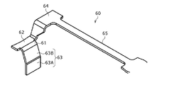
- FIG. 5 is a perspective view of the negative electrode lead 60.
- the negative electrode lead 60 is connected to the shoulder portion 25C (negative electrode terminal) of the outer can 25 of the power storage device 20 looking through the notch 43 of the upper holder 40 as described above.
- the negative electrode lead 60 can be applied to either the power storage module 10 having the upper holder 40 or the power storage module 10 having the lower holder 50, but the following describes an example applied to the power storage module 10 having the upper holder 40. ..
- the negative electrode lead 60 is formed at the contact portion 61 that abuts on the side surface of the power storage device 20 and radially inside the contact portion 61, and is joined to the shoulder portion 25C of the outer can 25.
- the lead shoulder portion 62 as a shoulder portion including the portion and the contact portion 61 are formed on the outer side in the radial direction, and the contact portion 61 and the lead shoulder portion 62 are urged toward the inner side in the radial direction. It has a part 63.
- the contact portion 61 contacts the side surface of the power storage device 20 as described above. More specifically, the contact portion 61 abuts on the side surface of the upper end portion of the outer can 25. When the upper end portion of the outer can 25 is formed in an R shape, the contact portion 61 may be formed so as to abut in accordance with the R shape.
- the lead shoulder portion 62 is continuously formed inside the contact portion 61 in the radial direction, and as described above, is a portion that abuts on the shoulder portion 25C of the outer can 25 and is joined to the shoulder portion 25C of the outer can 25. including.
- the radial inner end position of the lead shoulder portion 62 is the same as the radial inner end position of the shoulder portion 25C of the outer can 25 when the contact portion 61 abuts on the side surface of the upper end portion of the outer can 25. Is preferable.
- one side of the lead shoulder portion 62 in the circumferential direction is connected to a rising portion 64 formed so as to be inclined toward the top surface of the upper holder 40.
- the rising portion 64 is connected to the fuse portion 65 on the top surface of the upper holder 40.
- the urging portion 63 extends from the contact portion 61 and is continuously formed on the outer side in the radial direction from the contact portion 61 as described above, and the contact portion 61 and the lead shoulder portion 62 are directed inward in the radial direction. To urge.
- the urging portion 63 abuts on the holder abutting portion 63A that abuts on the wall portion 41B (the surface that intersects the end portion of the power storage device 20) of the accommodating portion 41 of the upper holder 40, and is inclined from the holder abutting portion 63A. It is formed from a connecting portion 63B connected to the portion 61.
- the urging portion 63 is formed as a leaf spring composed of the holder abutting portion 63A and the connecting portion 63B, and urges the abutting portion 61 against the wall portion 41B of the accommodating portion 41 of the upper holder 40.
- the abutting portion 61 and the lead shoulder portion 62 are urged inward in the radial direction with respect to the upper holder 40, so that the abutting portion 61 abuts on the side surface of the upper end portion of the outer can 25. Can be made to. Thereby, the position of the lead shoulder portion 62 in the shoulder portion 25C of the outer can 25 is determined. In other words, the urging portion 63 absorbs the variation in the gap between the upper holder 40 and the power storage device 20, and the mounting tolerance between the outer can 25 and the negative electrode lead 60.
- the position of the negative electrode lead 60 can be aligned with the proper joining position of the shoulder portion 25C of the outer can 25 with high accuracy.
- the mounting tolerance between the outer can 25 and the negative electrode lead 60 can be reduced, and the bonding region between the outer can 25 and the negative electrode lead 60 can be increased.
- the accuracy of the alignment of the joining tool can be relaxed, and the efficiency of the joining work can be improved.
- the urging portion 63 extends downward from the lead shoulder portion 62, it is possible to suppress obstruction of the joining work even if a joining tool larger than the lead shoulder portion 62 is used.
- the urging portion 63 is in contact with the wall portion 41B, when the urging portion 63 urges the negative electrode lead 60 to the side surface of the power storage device 20, the negative electrode lead 60 is connected to the lead shoulder portion 62. Deformation on the portion 32 side is likely to be suppressed.
- FIG. 6 is a detailed view of part A in FIG.
- FIG. 7 is a plan view of part A in FIG.
- FIG. 8 is a perspective view of the negative electrode lead 70.
- the negative electrode lead 70 is connected to the shoulder portion 25C (negative electrode terminal) of the outer can 25 of the power storage device 20 looking through the notch 43 of the upper holder 40 as described above. Since the details of the upper holder 40 and the power storage device 20 have been described above, the description thereof will be omitted.
- the negative electrode lead 70 is formed at the contact portion 71 that abuts on the side surface of the power storage device 20 and radially inside the contact portion 71, and is joined to the shoulder portion 25C of the outer can 25.
- the lead shoulder portion 72 as a shoulder portion including the portion and the contact portion 71 are formed radially outside the contact portion 71, and the contact portion 71 and the lead shoulder portion 72 are urged toward the inside in the radial direction. It has a part 73.
- the contact portion 71 contacts the side surface of the power storage device 20 as described above. More specifically, the contact portion 71 abuts on the side surface of the upper end portion of the outer can 25. When the upper end portion of the outer can 25 is formed in an R shape, the contact portion 71 may be formed so as to abut in accordance with the R shape.
- the lead shoulder portion 72 is continuously formed inside the contact portion 71 in the radial direction, and as described above, is a portion that abuts on the shoulder portion 25C of the outer can 25 and is joined to the shoulder portion 25C of the outer can 25. including.
- the radial inner end position of the lead shoulder portion 72 is the same as the radial inner end position of the shoulder portion 25C of the outer can 25 when the contact portion 71 abuts on the side surface of the upper end portion of the outer can 25. Is preferable.
- the urging portion 73 is continuously formed on the outer side in the radial direction from the abutting portion 71, and urges the abutting portion 71 and the lead shoulder portion 72 toward the inner side in the radial direction.
- the urging portion 73 includes a holder abutting portion 73A that abuts on the wall portion 43B of the notch portion 43 of the upper holder 40, and a connecting portion 73B that is bent from the holder abutting portion 73A to connect the abutting portion 71. Formed from.
- the urging portion 73 is formed as a substantially V-shaped (or U-shaped) leaf spring composed of the holder contact portion 73A and the connecting portion 73B, and hits the wall portion 43B of the accommodating portion 41 of the upper holder 40.
- the contact portion 61 is urged.
- the upper end portion of the holder contact portion 73A is formed so as to extend to the top surface of the upper holder 40, and the upper end portion of the holder contact portion 73A is connected to the negative electrode lead connection portion 75 on the top surface of the upper holder 40. ing.
- the abutting portion 71 and the lead shoulder portion 72 are urged inward in the radial direction with respect to the upper holder 40, so that the abutting portion 71 abuts on the side surface of the upper end portion of the outer can 25. Can be made to. Thereby, the position of the outer can 25 of the lead shoulder portion 72 on the shoulder portion 25C is determined.
- the urging portion 63 absorbs the variation in the gap between the upper holder 40 and the power storage device 20, and the mounting tolerance between the outer can 25 and the negative electrode lead 60.
- the position of the negative electrode lead 70 can be aligned with the proper joining position of the shoulder portion 25C of the outer can 25 with high accuracy.
- the attachment intersection between the outer can 25 and the negative electrode lead 70 can be reduced, and the bonding region between the outer can 25 and the negative electrode lead 70 can be increased.
- the accuracy of the alignment of the joining tool can be relaxed, and the efficiency of the joining work can be improved.
- the urging portion 73 also extends below the lead shoulder portion 72 when extending radially outward from the abutting portion 71 like the urging portion 63, it becomes easy to use a large joining tool.
- the urging portion 73 is in contact with the wall portion 43B, when the urging portion 73 urges the negative electrode lead 70 to the side surface of the power storage device 20, the negative electrode lead 70 is connected to the urging portion 73. Deformation on the portion 32 side is likely to be suppressed. Further, the urging portion 73 is configured to be tapered from the top surface of the upper holder 40 toward the bottom surface. Therefore, it can be easily inserted into the space inside the upper holder 40 such as the notch 43.
- FIG. 9 is a detailed view of part A in FIG.
- FIG. 10 is a plan view of part A in FIG.
- FIG. 11 is a perspective view of the negative electrode lead 80.
- the negative electrode lead 80 is connected to the shoulder portion 25C (negative electrode terminal) of the outer can 25 of the power storage device 20 looking through the notch 43 of the upper holder 40 as described above. Since the details of the upper holder 40 and the power storage device 20 have been described above, the description thereof will be omitted.
- the negative electrode lead 80 is formed at the contact portion 81 that abuts on the side surface of the power storage device 20 and radially inside the contact portion 81, and is joined to the shoulder portion 25C of the outer can 25.
- a lead shoulder portion 82 as a shoulder portion including a portion including a portion thereof, and an urging portion 83 formed in the middle of a fuse portion 85 described later and urging the contact portion 81 and the lead shoulder portion 82 inward in the radial direction.
- the contact portion 81 contacts the side surface of the power storage device 20 as described above. More specifically, the contact portion 81 abuts on the side surface of the upper end portion of the outer can 25. When the upper end portion of the outer can 25 is formed in an R shape, the contact portion 81 may be formed so as to abut in accordance with the R shape. The contact portion 81 is formed so as to extend from the lead shoulder portion 82.
- the lead shoulder portion 82 is continuously formed inside the contact portion 81 in the radial direction, abuts on the shoulder portion 25C of the outer can 25, and is joined to the shoulder portion 25C of the outer can 25. including.
- the radial inner end position of the lead shoulder portion 82 is the same as the radial inner end position of the shoulder portion 25C of the outer can 25 when the contact portion 81 abuts on the side surface of the upper end portion of the outer can 25. Is preferable.
- the contact portion 81 is connected to the central portion in the width direction (circumferential direction of the power storage device 20), and the rising portions 84 are connected to both ends in the width direction.
- the rising portion 84 extends to the top surface of the upper holder 40 and is connected to the fuse portion 85 connected to the connecting portion 32 of the current collecting member 30 on the top surface of the upper holder 40.
- the urging portion 83 is formed in the middle of the fuse portion 85 as described above, and urges the contact portion 81 and the lead shoulder portion 82 inward in the radial direction.
- the urging portion 83 is formed in an inverted U shape and acts as a leaf spring.
- the contact portion 81 can be brought into contact with the side surface of the upper end portion of the outer can 25 by urging the contact portion 81 and the lead shoulder portion 82 inward in the radial direction.
- the position of the lead shoulder portion 82 of the outer can 25 on the shoulder portion 25C is determined.
- the urging portion 63 absorbs the variation in the gap between the upper holder 40 and the power storage device 20, and the mounting tolerance between the outer can 25 and the negative electrode lead 60.
- the position of the negative electrode lead 80 can be aligned with the proper joining position of the shoulder portion 25C of the outer can 25 with high accuracy.
- the attachment intersection between the outer can 25 and the negative electrode lead 80 can be reduced, and the bonding region between the outer can 25 and the negative electrode lead 80 can be increased.
- the accuracy of the alignment of the joining tool can be relaxed, and the efficiency of the joining work can be improved.
- the urging portion 83 is not inserted into the space inside the upper holder 40 such as the notch portion 43, and the urging portion 83 is arranged outside the accommodating portion 41 and the notch portion 43. Has been done. Therefore, when the lead shoulder portion 82 is brought close to the shoulder portion 25C in order to bring the lead shoulder portion 82 into contact with the shoulder portion 25C, the urging portion 83 rubs or catches on the surface of the notch portion 43 or the like, and the lead shoulder portion 82 is described above. It is possible to reduce the possibility that the work of contacting the shoulder portion 25C with the shoulder portion 25C is hindered.
Abstract
少なくとも一つの円筒形の蓄電装置を備え、蓄電装置の上端部には、正極端子及び負極端子が配置され、負極端子は、蓄電装置の径方向において、正極端子よりも外側に配置され、負極端子に径方向の外側から電気的に接続される負極リードをさらに備え、負極リードは、蓄電装置の側面に当接する当接部と、当接部よりも径方向の内側に形成されて負極端子との接合部を含む肩部とを有する。
Description
本開示は、蓄電モジュールに関する。
従来、蓄電モジュールは、複数の蓄電装置を備える電源として公知である。例えば、特許文献1に開示される蓄電モジュールは、複数の円筒形電池を備える。この円筒形電池では、封口体が正極端子として構成されると共に外装缶が負極端子として構成され、外装缶の肩部(加締められた開口端部)に負極リードが接合される。
しかし、負極リードと正極端子とは絶縁距離を確保する必要があり、外装缶に負極リードを接合するにあたって、外装缶における適正な接合位置に負極リードの位置を高い精度で合わせる必要がある。
本開示の目的は、上記負極リードのように、外装缶における適正な接合位置にリードの位置を高い精度で合わせることができる蓄電モジュールを提供することである。
本開示の一態様である蓄電モジュールは、少なくとも一つの円筒形の蓄電装置を備え、蓄電装置の一側の端部には、第1の端子及び第2の端子が配置され、第2の端子は、蓄電装置の径方向において、第1の端子よりも外側に配置され、第2の端子に径方向の外側から電気的に接続されるリードをさらに備え、リードは、蓄電装置の側面に当接する当接部と、当接部よりも径方向の内側に形成されて第2の端子との接合部を含む肩部と、を有する。
本開示の一態様によれば、第2の端子における適正な接合位置にリードの位置を高い精度で合わせることができる。これにより、第2の端子とリードとの取り付け公差を小さくすることができる。
以下、図面を用いて本開示の実施形態を説明する。以下で説明する形状、材料及び個数は例示であって、蓄電モジュールの仕様に応じて適宜変更することができる。
図1を用いて、実施形態に係る蓄電モジュール10について説明する。図1は、蓄電モジュール10を示す側断面図である。以下では、蓄電モジュール10及び蓄電装置20についてホルダとしての上ホルダ40が蓄電装置20を保持する側を上下方向の上側として説明する。しかし、上ホルダ40が蓄電モジュール10の下側であってもよい。
蓄電モジュール10は、主として動力用の電源として使用される。蓄電モジュール10は、例えば、電気自動車、電動工具、電動アシスト自転車、電動バイク、電動車椅子、電動三輪車、電動カート等のモータで駆動される電動機器の電源として使用される。ただし、蓄電モジュール10の用途は限定されることなく、例えば、クリーナー、無線機、照明装置、デジタルカメラ、ビデオカメラ等の屋内外で使用される種々の電気機器の電源として使用されてもよい。
図1では、蓄電モジュール10は、複数の円筒形の蓄電装置20と、蓄電装置20の第1の端子(正極端子)及び第2の端子(負極端子)から集電する集電部材30と、複数の蓄電装置20の上端側をそれぞれ保持するホルダとしての上ホルダ40と、複数の蓄電装置20の下端側をそれぞれ保持する下ホルダ50と、を備える。集電部材30及び上ホルダ40について詳細は後述する。
図2を用いて、実施形態に係る集電部材30について説明する。図2は、集電部材30を示す平面図である。
集電部材30は、板状の金属材料(金属箔)から形成され、上ホルダ40の頂面に設けられる。集電部材30は、蓄電装置20の正極端子に接続される正極リード31と、正極リード31同士を連結する連結部32と、蓄電装置20の負極端子に接続されるリードとして負極リード60とが形成される。負極リード60は、負極リード60と連結部32とを連結するヒューズ部65を含む。負極リード60について詳細は後述する。
正極リード31は、後述する上ホルダ40の開口部42の上方に延出して、後述する正極端子としての封口体26の頂面に接合される。連結部32は、帯状又はシート状に形成される。負極リード60は、後述する上ホルダ40の切り欠き部43の上方に延出して、後述する負極端子としての外装缶25の肩部25Cに接合される。ヒューズ部65は、連結部32よりも幅狭の帯状に形成され、上ホルダ40の開口部42及び切り欠き部43に重なることなく設けられる。なお、本開示の蓄電装置において、ヒューズ部65は設けなくてもよい。
集電部材30によれば、蓄電装置20の正極端子と負極端子との接続と、複数の蓄電装置20の集電との機能を1枚の金属箔で実現しているので、集電のロスを小さく抑えることができる。また、集電部材30によれば、1枚の金属箔で形成されているため、エッチング等で精度良く低コストで加工することができる。
図3を用いて、実施形態に係わる蓄電装置20について説明する。図3は、図1のA部の詳細図である。以下では、蓄電装置20の円筒形状の径方向及び周方向に従って各部材を説明する。
蓄電装置20は、円筒形のリチウムイオン二次電池が用いられる。蓄電装置20は、リチウムイオン二次電池に限定されることなく、ニッケル水素電池、キャパシタ等であってもよい。
蓄電装置20は、詳細は後述するが、上端部において第1の端子としての正極端子及び第2の端子としての負極端子が配置されている。負極端子が正極端子の周囲を囲うように配置されることにより負極端子が正極端子よりも径方向外側に配置される。より具体的には、正極端子が後述する封口体26の頂面に構成される。また、負極端子が後述する外装缶25の加締められた開口端部(以下、肩部25C)に構成される。
蓄電装置20は、例えば帯状の正極21と帯状の負極22とが帯状のセパレータ23を介した状態で巻回された電極群24と、電極群24を電解液と共に収容した円筒状の外装缶25と、外装缶25の開口を絶縁した状態で封止する封口体26と、正極21と封口体26とを電気的に接続する箔状の正極タブ27と、負極22と外装缶25とを電気的に接続する負極タブ(図示なし)とを有する。封口体26の外周と外装缶25の開口の内周面との間には、絶縁性のガスケット28が配置されている。なお蓄電装置20は、外装缶25に正極タブ27が接続し、封口体26に負極タブを接続してもよい。この場合、第2の端子は正極端子になる。負極リード60としていたリードは正極のリードとして用いられる。
外装缶25の外周面には、開口側に環状の溝部25Aが形成されている。この溝部25Aは、対応する外装缶25の内周面において環状の凸部25Bが形成される。ガスケット28及び封口体26は、外装缶25内において、この環状の凸部25B上に配置される。さらに、外装缶25の肩部25Cが、内周側にガスケット28を配置した状態で外装缶25の内側に向かって倒れるように加締められている。加締められた肩部25Cと凸部25Bとにより封口体26がガスケット28を介して上下方向に挟まれることにより、外装缶25の開口は封止される。
なお、肩部25Cは、上述した構成に限定されない。例えば封口体26の中央部に端子板と、この端子板と絶縁された状態で封口体26の最外周に配置された導電性の接合部を有し、開口端部とこの接合部を溶接接合することで外装缶25の開口を封止してもよい。このとき、負極リード60は、接合部の頂面と接続してもよい。
封口体26には、電流遮断機構(CID)や、外装缶25内が所定の圧力以上に達した場合に破裂する排気弁を設けてもよい。また、電極群24と凸部25Bとの間に電極群24と外装缶25とを絶縁するための絶縁板29を設けてもよい。絶縁板29が設けられる場合は、正極タブ27は絶縁板29に形成した貫通孔を通って延びてもよい。さらに、電極群24と外装缶25の底部との間に電極群24と外装缶25とを絶縁するための絶縁板を設けてもよい。負極タブは、絶縁板に形成した貫通孔を通っても、絶縁板を迂回して延びてもよい。
蓄電装置20では、上述したように正極端子が封口体26の頂面に構成され、正極集電箔と接続される正極リード31(図2参照)が接合される。また、蓄電装置20では、上述したように負極端子が外装缶25の加締められた肩部25Cに構成され、負極集電箔と接続される負極タブが外装缶25の底部と接合される。負極リード60は、蓄電装置20の径方向外側から外装缶25の肩部25Cに接合される。
図3を用いて、実施形態に係る上ホルダ40について説明する。
上ホルダ40は、複数の蓄電装置20の上端側を保持する部材である。上ホルダ40は、熱可塑性樹脂によって形成される。熱可塑性樹脂としては、汎用プラスチックとエンジニアリングプラスチックとに大別され、ポリエチレン、ポリプロピレン、ポリアミド、ABS等が用いられる。
図3では、上ホルダ40の底面には、それぞれの蓄電装置20の上端側が収容される複数の収容部41が形成される。収容部41に蓄電装置20の上端側が嵌合することによって、蓄電装置20の上端側が上ホルダ40に保持される。
収容部41は、蓄電装置20の上端面と対向する底面を有する天井部41Aと、蓄電装置20の側周面と対向する内周面を有する壁部41Bとを含む凹部として上ホルダ40の底面に形成される。収容部41の周囲には、蓄電装置20の封口体26の頂面を上ホルダ40の上面を露出させる開口部42と、蓄電装置20の外装缶25の肩部25Cを上ホルダ40の上面から露出させる切り欠き部43とが形成される。
開口部42は、収容部41の天井部41Aが円状に開口された部分である。開口部42の直径は、壁部41Bの内径よりも小さく形成される。開口部42によれば、蓄電装置20の封口体26の頂面が上ホルダ40の上面から露出する。そのため、開口部42を介して封口体26の頂面と正極リード31と接合させることができる。また、天井部41Aの底部は蓄電装置20と当接していてもよい。
切り欠き部43は、開口部42の縁部の一部が切り欠かれて形成される部分である。切り欠き部43によれば、蓄電装置20の外装缶25の肩部25Cの一部が上ホルダ40の上面から露出できる。切り欠き部43の内周面(収容部41の壁部41Bと平行な面)を壁部43Bとする。
図3から図5を用いて、第1実施形態に係る負極リード60について説明する。図4は、図1のA部の平面図である。図5は、負極リード60の斜視図である。
図3では、負極リード60は、上述したように上ホルダ40の切り欠き部43から覗く蓄電装置20の外装缶25の肩部25C(負極端子)に接続される。負極リード60は、上ホルダ40を有する蓄電モジュール10、又は下ホルダ50を有する蓄電モジュール10のどちらにも適用できるが、以下では、上ホルダ40を有する蓄電モジュール10に適用される例について説明する。
図5及び図6では、負極リード60は、蓄電装置20の側面に当接する当接部61と、当接部61よりも径方向の内側に形成され、外装缶25の肩部25Cに接合される部分を含む肩部としてのリード肩部62と、当接部61よりも径方向の外側に形成され、当接部61及びリード肩部62を径方向の内側に向けて付勢する付勢部63とを有する。
当接部61は、上述したように蓄電装置20の側面に当接する。より詳細には、当接部61は、外装缶25の上端部の側面に当接する。当接部61は、外装缶25の上端部がR状に形成されている場合は、R状に倣って当接するように形成されてもよい。
リード肩部62は、当接部61よりも径方向の内側に連続して形成され、上述したように外装缶25の肩部25Cに当接し、外装缶25の肩部25Cに接合される部分を含む。リード肩部62の径方向の内端位置は、当接部61が外装缶25の上端部の側面に当接したときに、外装缶25の肩部25Cの径方向の内端位置と同一位置であることが好ましい。
本例では、リード肩部62の周方向の一側には、上ホルダ40の頂面に向かって傾斜して形成される立ち上がり部64と接続されている。立ち上がり部64は、上ホルダ40の頂面においてヒューズ部65と接続されている。
付勢部63は、当接部61から延びて上述したように当接部61よりも径方向の外側に連続して形成され、当接部61及びリード肩部62を径方向の内側に向けて付勢する。付勢部63は、上ホルダ40の収容部41の壁部41B(蓄電装置20の端部と交差する面)に当接するホルダ当接部63Aと、ホルダ当接部63Aから傾斜して当接部61と接続される接続部63Bとから形成される。これにより、付勢部63は、ホルダ当接部63Aと接続部63Bとからなる板バネとして形成され、上ホルダ40の収容部41の壁部41Bに対し当接部61を付勢する。
付勢部63によれば、上ホルダ40に対し当接部61及びリード肩部62を径方向の内側に付勢することによって、当接部61を外装缶25の上端部の側面に当接させることができる。これにより、外装缶25の肩部25Cにおけるリード肩部62の位置が決定される。換言すれば、付勢部63によって、上ホルダ40と蓄電装置20との隙間ばらつき、外装缶25と負極リード60との取り付け公差が吸収される。
負極リード60によれば、外装缶25の肩部25Cの適正な接合位置に負極リード60の位置を高い精度で合わせることができる。これにより、外装缶25と負極リード60との取り付け公差を小さくすることができ、外装缶25と負極リード60との接合領域を大きくすることができる。さらに、外装缶25と負極リード60との接合領域を大きくすることによって、接合ツールの位置合わせの精度を緩和することができ、接合作業の効率を向上させることができる。また、付勢部63がリード肩部62より下方に延びているため、リード肩部62より大きい接合ツールを用いても接合作業を阻害することを抑制できる。また、付勢部63を壁部41Bに当接させているため、付勢部63が負極リード60を蓄電装置20の側面を付勢する際、負極リード60のうち、リード肩部62より連結部32側における変形が抑制されやすい。
図6から図8を用いて、第2実施形態に係る負極リード70について説明する。図6は、図1のA部の詳細図である。図7は、図1のA部の平面図である。図8は、負極リード70の斜視図である。
図6では、負極リード70は、上述したように上ホルダ40の切り欠き部43から覗く蓄電装置20の外装缶25の肩部25C(負極端子)に接続される。上ホルダ40及び蓄電装置20の詳細は上述したので説明を省略する。
図7及び図8では、負極リード70は、蓄電装置20の側面に当接する当接部71と、当接部71よりも径方向の内側に形成され、外装缶25の肩部25Cに接合される部分を含む肩部としてのリード肩部72と、当接部71よりも径方向の外側に形成され、当接部71及びリード肩部72を径方向の内側に向けて付勢する付勢部73とを有する。
当接部71は、上述したように蓄電装置20の側面に当接する。より詳細には、当接部71は、外装缶25の上端部の側面に当接する。当接部71は、外装缶25の上端部がR状に形成されている場合は、R状に倣って当接するように形成されてもよい。
リード肩部72は、当接部71よりも径方向の内側に連続して形成され、上述したように外装缶25の肩部25Cに当接し、外装缶25の肩部25Cに接合される部分を含む。リード肩部72の径方向の内端位置は、当接部71が外装缶25の上端部の側面に当接したときに、外装缶25の肩部25Cの径方向の内端位置と同一位置であることが好ましい。
付勢部73は、上述したように当接部71よりも径方向の外側に連続して形成され、当接部71及びリード肩部72を径方向の内側に向けて付勢する。付勢部73は、上ホルダ40の切り欠き部43の壁部43Bに当接するホルダ当接部73Aと、ホルダ当接部73Aから折り曲げられて当接部71とを接続される接続部73Bとから形成される。これにより、付勢部73は、ホルダ当接部73Aと接続部73Bとからなる略V状(又はU状)の板バネとして形成され、上ホルダ40の収容部41の壁部43Bに対し当接部61を付勢する。
本例では、ホルダ当接部73Aの上端部が上ホルダ40の頂面まで延出して形成され、上ホルダ40の頂面においてホルダ当接部73Aの上端部が負極リード接続部75と接続されている。
付勢部73によれば、上ホルダ40に対し当接部71及びリード肩部72を径方向の内側に付勢することによって、当接部71を外装缶25の上端部の側面に当接させることができる。これにより、リード肩部72の外装缶25の肩部25Cにおける位置が決定される。換言すれば、付勢部63によって、上ホルダ40と蓄電装置20との隙間ばらつき、外装缶25と負極リード60との取り付け公差が吸収される。
負極リード70によれば、外装缶25の肩部25Cの適正な接合位置に負極リード70の位置を高い精度で合わせることができる。これにより、外装缶25と負極リード70との取り付け交差を小さくすることができ、外装缶25と負極リード70との接合領域を大きくすることができる。さらに、外装缶25と負極リード70との接合領域を大きくすることによって、接合ツールの位置合わせの精度を緩和することができ、接合作業の効率を向上させることができる。また、付勢部73も付勢部63と同様に当接部71から径方向の外側に延びる際にリード肩部72より下方にも延びているため、大きな接合ツールを用い易くなる。また、付勢部73を壁部43Bに当接させているため、付勢部73が負極リード70を蓄電装置20の側面を付勢する際、負極リード70のうち、付勢部73より連結部32側における変形が抑制されやすい。さらに、付勢部73は上ホルダ40の頂面から底面に向かって細くなるように構成されている。そのため、切り欠き部43等の上ホルダ40内の空間へ容易に挿入が可能である。
図9から図11を用いて、第3実施形態に係る負極リード80について説明する。図9は、図1のA部の詳細図である。図10は、図1のA部の平面図である。図11は、負極リード80の斜視図である。
図9では、負極リード80は、上述したように上ホルダ40の切り欠き部43から覗く蓄電装置20の外装缶25の肩部25C(負極端子)に接続される。上ホルダ40及び蓄電装置20の詳細は上述したので説明を省略する。
図10及び図11では、負極リード80は、蓄電装置20の側面に当接する当接部81と、当接部81よりも径方向の内側に形成され、外装缶25の肩部25Cに接合される部分を含む肩部としてのリード肩部82と、後述するヒューズ部85の途中に形成され、当接部81及びリード肩部82を径方向の内側に向けて付勢する付勢部83とを有する。
当接部81は、上述したように蓄電装置20の側面に当接する。より詳細には、当接部81は、外装缶25の上端部の側面に当接する。当接部81は、外装缶25の上端部がR状に形成されている場合は、R状に倣って当接するように形成されてもよい。当接部81は、リード肩部82から延びて形成されている。
リード肩部82は、上述したように当接部81よりも径方向の内側に連続して形成され、外装缶25の肩部25Cに当接し、外装缶25の肩部25Cに接合される部分を含む。リード肩部82の径方向の内端位置は、当接部81が外装缶25の上端部の側面に当接したときに、外装缶25の肩部25Cの径方向の内端位置と同一位置であることが好ましい。
リード肩部82の径方向外側には、幅方向(蓄電装置20の周方向)の中央部に当接部81が接続され、幅方向の両端部に立ち上がり部84が接続されている。立ち上がり部84は、上ホルダ40の頂面まで延出され、上ホルダ40の頂面において集電部材30の連結部32と接続されるヒューズ部85に接続される。
付勢部83は、上述したようにヒューズ部85の途中に形成され、当接部81及びリード肩部82を径方向の内側に向けて付勢する。本例では、付勢部83は、逆U状に形成され、板バネとして作用する。
付勢部83によれば、当接部81及びリード肩部82を径方向の内側に付勢することによって、当接部81を外装缶25の上端部の側面に当接させることができる。これにより、リード肩部82の外装缶25の肩部25Cにおける位置が決定される。換言すれば、付勢部63によって、上ホルダ40と蓄電装置20との隙間ばらつき、外装缶25と負極リード60との取り付け公差が吸収される。
負極リード80によれば、外装缶25の肩部25Cの適正な接合位置に負極リード80の位置を高い精度で合わせることができる。これにより、外装缶25と負極リード80との取り付け交差を小さくすることができ、外装缶25と負極リード80との接合領域を大きくすることができる。さらに、外装缶25と負極リード80との接合領域を大きくすることによって、接合ツールの位置合わせの精度を緩和することができ、接合作業の効率を向上させることができる。また、本実施形態の負極リード80では、付勢部83を切り欠き部43などの上ホルダ40内の空間へ挿入せず、収容部41や切り欠き部43の外に付勢部83が配置されている。そのため、リード肩部82を肩部25Cに当接させようとリード肩部82を肩部25Cへ近づける場合、付勢部83が切り欠き部43などの表面とこすれる又はひっかかって上記リード肩部82を肩部25Cへ当接させる作業が阻害される可能性を低減できる。
なお、本発明は上述した実施形態及びその変形例に限定されるものではなく、本願の特許請求の範囲に記載された事項の範囲内において種々の変更や改良が可能であることは勿論である。
10 蓄電モジュール、20 蓄電装置、21 正極、22 負極、23 セパレータ、24 電極群、25 外装缶、25A 溝部、25B 凸部、25C 肩部、26 封口体、27 正極タブ、28 ガスケット、29 絶縁板、30 集電部材、31 正極リード、32 連結部、40 上ホルダ、41 収容部、41A 天井部、41B 壁部、42 開口部、43 切り欠き部、43B 壁部、50 下ホルダ、60 負極リード、61 当接部、62 リード肩部(肩部)、63 付勢部、63A ホルダ当接部、63B 接続部、64 立ち上がり部、65 ヒューズ部、70 負極リード、71 当接部、72 リード肩部(肩部)、73 付勢部、73A ホルダ当接部、73B 接続部、75 ヒューズ部、80 負極リード、81 当接部、82 リード肩部(肩部)、83 付勢部、84 立ち上がり部、85 ヒューズ部
Claims (7)
- 少なくとも一つの円筒形の蓄電装置を備え、
前記蓄電装置の一側の端部には、第1の端子及び第2の端子が配置され、
前記第2の端子は、前記蓄電装置の径方向において、前記第1の端子よりも外側に配置され、
前記第2の端子に前記径方向の外側から電気的に接続されるリードをさらに備え、
前記リードは、
前記蓄電装置の側面に当接する当接部と、
前記当接部よりも前記径方向の内側に形成されて前記第2の端子との接合部を含む肩部と、
を有する、
蓄電モジュール。 - 請求項1に記載の蓄電モジュールであって、
前記リードは、前記当接部よりも前記径方向の外側に形成される付勢部をさらに有し、
前記付勢部は、前記当接部及び前記肩部を前記蓄電装置の前記径方向の内側に向けて付勢する、
蓄電モジュール。 - 請求項2に記載の蓄電モジュールであって、
前記蓄電装置の一側を保持するホルダをさらに備え、
前記付勢部は、前記ホルダによって支持される、
蓄電モジュール。 - 請求項3に記載の蓄電モジュールであって、
前記ホルダは、前記蓄電装置の一側を収容する収容部を有し、
前記付勢部は、前記収容部の壁部に当接することによって前記ホルダによって支持される、
蓄電モジュール。 - 請求項4に記載の蓄電モジュールであって、
前記付勢部は、前記当接部から前記径方向の外側に延びると共に、前記ホルダにおいて、前記蓄電装置の前記端部と交差する面に当接する、
蓄電モジュール。 - 請求項4に記載の蓄電モジュールであって、
前記ホルダは、前記第1の端子を露出させる開口部と、前記開口部の周囲に形成され、前記第2の端子を露出させる切り欠き部と、を有し、
前記付勢部は、前記切り欠き部の壁部に当接することによって前記ホルダによって支持される、
蓄電モジュール。 - 請求項2に記載の蓄電モジュールであって、
前記蓄電装置の一側を保持するホルダをさらに備え、
前記付勢部は、前記ホルダにおいて径方向に延びた一側の面に設けられる、
蓄電モジュール。
Priority Applications (4)
| Application Number | Priority Date | Filing Date | Title |
|---|---|---|---|
| US18/041,692 US20230369722A1 (en) | 2020-09-30 | 2021-09-17 | Electric power storage module |
| CN202180055275.3A CN116157885A (zh) | 2020-09-30 | 2021-09-17 | 蓄电模块 |
| EP21875274.9A EP4224498A4 (en) | 2020-09-30 | 2021-09-17 | ELECTRICAL ENERGY STORAGE MODULE |
| JP2022553825A JPWO2022070972A1 (ja) | 2020-09-30 | 2021-09-17 |
Applications Claiming Priority (2)
| Application Number | Priority Date | Filing Date | Title |
|---|---|---|---|
| JP2020-164747 | 2020-09-30 | ||
| JP2020164747 | 2020-09-30 |
Publications (1)
| Publication Number | Publication Date |
|---|---|
| WO2022070972A1 true WO2022070972A1 (ja) | 2022-04-07 |
Family
ID=80951445
Family Applications (1)
| Application Number | Title | Priority Date | Filing Date |
|---|---|---|---|
| PCT/JP2021/034223 WO2022070972A1 (ja) | 2020-09-30 | 2021-09-17 | 蓄電モジュール |
Country Status (5)
| Country | Link |
|---|---|
| US (1) | US20230369722A1 (ja) |
| EP (1) | EP4224498A4 (ja) |
| JP (1) | JPWO2022070972A1 (ja) |
| CN (1) | CN116157885A (ja) |
| WO (1) | WO2022070972A1 (ja) |
Citations (6)
| Publication number | Priority date | Publication date | Assignee | Title |
|---|---|---|---|---|
| WO2015019822A1 (ja) * | 2013-08-09 | 2015-02-12 | 日立オートモティブシステムズ株式会社 | 蓄電モジュール |
| WO2019044582A1 (ja) * | 2017-08-31 | 2019-03-07 | パナソニックIpマネジメント株式会社 | 電池ブロック及びそれを備えた電池モジュール |
| WO2019058938A1 (ja) * | 2017-09-20 | 2019-03-28 | パナソニックIpマネジメント株式会社 | 電池モジュール |
| WO2019164974A1 (en) * | 2018-02-20 | 2019-08-29 | Nio Usa, Inc. | Uniform current density tapered busbar |
| WO2019244392A1 (ja) * | 2018-06-22 | 2019-12-26 | パナソニックIpマネジメント株式会社 | 電池モジュール |
| US10707471B2 (en) | 2018-03-22 | 2020-07-07 | Nio Usa, Inc. | Single side cell-to-cell battery module interconnection |
Family Cites Families (3)
| Publication number | Priority date | Publication date | Assignee | Title |
|---|---|---|---|---|
| CN107732047A (zh) * | 2016-08-10 | 2018-02-23 | 深圳市沃特玛电池有限公司 | 电动汽车底盘装置 |
| CN106654133A (zh) * | 2016-12-12 | 2017-05-10 | 深圳市沃特玛电池有限公司 | 一种电池模组 |
| CN109545546B (zh) * | 2018-12-21 | 2024-04-12 | 美尔森电气保护系统(上海)有限公司 | 一种基于叠层母排的电池或者电容器快速连接装置 |
-
2021
- 2021-09-17 WO PCT/JP2021/034223 patent/WO2022070972A1/ja unknown
- 2021-09-17 CN CN202180055275.3A patent/CN116157885A/zh active Pending
- 2021-09-17 JP JP2022553825A patent/JPWO2022070972A1/ja active Pending
- 2021-09-17 EP EP21875274.9A patent/EP4224498A4/en active Pending
- 2021-09-17 US US18/041,692 patent/US20230369722A1/en active Pending
Patent Citations (6)
| Publication number | Priority date | Publication date | Assignee | Title |
|---|---|---|---|---|
| WO2015019822A1 (ja) * | 2013-08-09 | 2015-02-12 | 日立オートモティブシステムズ株式会社 | 蓄電モジュール |
| WO2019044582A1 (ja) * | 2017-08-31 | 2019-03-07 | パナソニックIpマネジメント株式会社 | 電池ブロック及びそれを備えた電池モジュール |
| WO2019058938A1 (ja) * | 2017-09-20 | 2019-03-28 | パナソニックIpマネジメント株式会社 | 電池モジュール |
| WO2019164974A1 (en) * | 2018-02-20 | 2019-08-29 | Nio Usa, Inc. | Uniform current density tapered busbar |
| US10707471B2 (en) | 2018-03-22 | 2020-07-07 | Nio Usa, Inc. | Single side cell-to-cell battery module interconnection |
| WO2019244392A1 (ja) * | 2018-06-22 | 2019-12-26 | パナソニックIpマネジメント株式会社 | 電池モジュール |
Non-Patent Citations (1)
| Title |
|---|
| See also references of EP4224498A4 |
Also Published As
| Publication number | Publication date |
|---|---|
| EP4224498A4 (en) | 2024-04-24 |
| US20230369722A1 (en) | 2023-11-16 |
| CN116157885A (zh) | 2023-05-23 |
| EP4224498A1 (en) | 2023-08-09 |
| JPWO2022070972A1 (ja) | 2022-04-07 |
Similar Documents
| Publication | Publication Date | Title |
|---|---|---|
| JP4596289B2 (ja) | 密閉型電池 | |
| JP6491448B2 (ja) | 二次電池および電池モジュール | |
| CN111937186B (zh) | 电池以及电池模块 | |
| JP4974734B2 (ja) | 二次電池及び二次電池モジュール | |
| JP2011146379A (ja) | 二次電池 | |
| WO2021153439A1 (ja) | 蓄電装置 | |
| US7985499B2 (en) | Battery having electrode lead element with fixing member | |
| JP3751782B2 (ja) | 円筒型アルカリ蓄電池とその製造方法 | |
| WO2022070972A1 (ja) | 蓄電モジュール | |
| JP5510051B2 (ja) | 電池、車両及び電池搭載機器 | |
| WO2022024893A1 (ja) | 蓄電モジュール | |
| WO2022024895A1 (ja) | 蓄電モジュール | |
| KR20190084765A (ko) | 전극 탭-리드 결합부에 적용된 플라스틱 부재를 포함하는 전극조립체 및 이를 포함하는 이차전지 | |
| JP4656802B2 (ja) | アルカリ蓄電池 | |
| JP2019036412A (ja) | 密閉型電池 | |
| JP4168592B2 (ja) | 二次電池および二次電池の製造方法 | |
| WO2024095902A1 (ja) | 蓄電装置 | |
| WO2023054498A1 (ja) | 蓄電モジュール | |
| WO2024024419A1 (ja) | 電池パック | |
| JP7304372B2 (ja) | 二次電池 | |
| JP6677911B2 (ja) | 二次電池 | |
| JP2005190851A (ja) | 密閉型蓄電池 | |
| JP2003223879A (ja) | 組電池とその製造方法 |
Legal Events
| Date | Code | Title | Description |
|---|---|---|---|
| 121 | Ep: the epo has been informed by wipo that ep was designated in this application |
Ref document number: 21875274 Country of ref document: EP Kind code of ref document: A1 |
|
| ENP | Entry into the national phase |
Ref document number: 2022553825 Country of ref document: JP Kind code of ref document: A |
|
| NENP | Non-entry into the national phase |
Ref country code: DE |
|
| ENP | Entry into the national phase |
Ref document number: 2021875274 Country of ref document: EP Effective date: 20230502 |