WO2022070722A1 - Flexible tube for endoscope, endoscope-type medical device, and methods for producing these - Google Patents
Flexible tube for endoscope, endoscope-type medical device, and methods for producing these Download PDFInfo
- Publication number
- WO2022070722A1 WO2022070722A1 PCT/JP2021/031740 JP2021031740W WO2022070722A1 WO 2022070722 A1 WO2022070722 A1 WO 2022070722A1 JP 2021031740 W JP2021031740 W JP 2021031740W WO 2022070722 A1 WO2022070722 A1 WO 2022070722A1
- Authority
- WO
- WIPO (PCT)
- Prior art keywords
- flexible tube
- base material
- layer
- endoscope
- polymer coating
- Prior art date
Links
- 238000000034 method Methods 0.000 title claims description 20
- 229920000642 polymer Polymers 0.000 claims abstract description 113
- 239000000463 material Substances 0.000 claims abstract description 105
- 229910052751 metal Inorganic materials 0.000 claims abstract description 41
- 239000002184 metal Substances 0.000 claims abstract description 41
- 239000006087 Silane Coupling Agent Substances 0.000 claims abstract description 36
- 238000004519 manufacturing process Methods 0.000 claims abstract description 21
- 239000010410 layer Substances 0.000 claims description 163
- 239000011247 coating layer Substances 0.000 claims description 87
- 229920001971 elastomer Polymers 0.000 claims description 46
- 239000000806 elastomer Substances 0.000 claims description 46
- 229920003225 polyurethane elastomer Polymers 0.000 claims description 34
- 229920000728 polyester Polymers 0.000 claims description 30
- 229920002725 thermoplastic elastomer Polymers 0.000 claims description 20
- 239000004952 Polyamide Substances 0.000 claims description 18
- 239000007822 coupling agent Substances 0.000 claims description 18
- 229920002647 polyamide Polymers 0.000 claims description 18
- 238000003780 insertion Methods 0.000 claims description 11
- 230000037431 insertion Effects 0.000 claims description 11
- 229910001220 stainless steel Inorganic materials 0.000 claims description 11
- 239000010935 stainless steel Substances 0.000 claims description 11
- 238000002161 passivation Methods 0.000 claims description 8
- 239000011148 porous material Substances 0.000 claims description 7
- FZHAPNGMFPVSLP-UHFFFAOYSA-N silanamine Chemical compound [SiH3]N FZHAPNGMFPVSLP-UHFFFAOYSA-N 0.000 claims description 7
- 239000000126 substance Substances 0.000 abstract description 20
- 238000009954 braiding Methods 0.000 abstract description 5
- 238000000465 moulding Methods 0.000 description 20
- 239000011248 coating agent Substances 0.000 description 17
- 238000000576 coating method Methods 0.000 description 17
- -1 polydimethylene Polymers 0.000 description 17
- 239000002861 polymer material Substances 0.000 description 16
- RTZKZFJDLAIYFH-UHFFFAOYSA-N Diethyl ether Chemical compound CCOCC RTZKZFJDLAIYFH-UHFFFAOYSA-N 0.000 description 14
- LYCAIKOWRPUZTN-UHFFFAOYSA-N Ethylene glycol Chemical compound OCCO LYCAIKOWRPUZTN-UHFFFAOYSA-N 0.000 description 14
- 239000007788 liquid Substances 0.000 description 13
- 230000015572 biosynthetic process Effects 0.000 description 12
- KFSLWBXXFJQRDL-UHFFFAOYSA-N Peracetic acid Chemical compound CC(=O)OO KFSLWBXXFJQRDL-UHFFFAOYSA-N 0.000 description 10
- 239000012790 adhesive layer Substances 0.000 description 10
- 229920005862 polyol Polymers 0.000 description 10
- 230000000052 comparative effect Effects 0.000 description 9
- 239000002356 single layer Substances 0.000 description 9
- 239000004721 Polyphenylene oxide Substances 0.000 description 8
- 150000002009 diols Chemical class 0.000 description 8
- 238000011156 evaluation Methods 0.000 description 8
- 238000001125 extrusion Methods 0.000 description 8
- 230000001965 increasing effect Effects 0.000 description 8
- 239000005056 polyisocyanate Substances 0.000 description 8
- 229920001228 polyisocyanate Polymers 0.000 description 8
- 239000000243 solution Substances 0.000 description 8
- 239000002904 solvent Substances 0.000 description 8
- XLYOFNOQVPJJNP-UHFFFAOYSA-N water Substances O XLYOFNOQVPJJNP-UHFFFAOYSA-N 0.000 description 8
- 229920000570 polyether Polymers 0.000 description 7
- 150000003077 polyols Chemical class 0.000 description 7
- 229920002635 polyurethane Polymers 0.000 description 7
- 239000004814 polyurethane Substances 0.000 description 7
- 239000011347 resin Substances 0.000 description 7
- 229920005989 resin Polymers 0.000 description 7
- ZWEHNKRNPOVVGH-UHFFFAOYSA-N 2-Butanone Chemical compound CCC(C)=O ZWEHNKRNPOVVGH-UHFFFAOYSA-N 0.000 description 6
- 238000006243 chemical reaction Methods 0.000 description 6
- WGCNASOHLSPBMP-UHFFFAOYSA-N hydroxyacetaldehyde Natural products OCC=O WGCNASOHLSPBMP-UHFFFAOYSA-N 0.000 description 6
- 239000003973 paint Substances 0.000 description 6
- 229920000515 polycarbonate Polymers 0.000 description 6
- 239000004417 polycarbonate Substances 0.000 description 6
- LFQSCWFLJHTTHZ-UHFFFAOYSA-N Ethanol Chemical compound CCO LFQSCWFLJHTTHZ-UHFFFAOYSA-N 0.000 description 5
- 125000003277 amino group Chemical group 0.000 description 5
- HEDRZPFGACZZDS-UHFFFAOYSA-N Chloroform Chemical compound ClC(Cl)Cl HEDRZPFGACZZDS-UHFFFAOYSA-N 0.000 description 4
- SECXISVLQFMRJM-UHFFFAOYSA-N N-Methylpyrrolidone Chemical compound CN1CCCC1=O SECXISVLQFMRJM-UHFFFAOYSA-N 0.000 description 4
- PPBRXRYQALVLMV-UHFFFAOYSA-N Styrene Chemical compound C=CC1=CC=CC=C1 PPBRXRYQALVLMV-UHFFFAOYSA-N 0.000 description 4
- RTAQQCXQSZGOHL-UHFFFAOYSA-N Titanium Chemical compound [Ti] RTAQQCXQSZGOHL-UHFFFAOYSA-N 0.000 description 4
- 229910052782 aluminium Inorganic materials 0.000 description 4
- XAGFODPZIPBFFR-UHFFFAOYSA-N aluminium Chemical compound [Al] XAGFODPZIPBFFR-UHFFFAOYSA-N 0.000 description 4
- 239000007864 aqueous solution Substances 0.000 description 4
- WERYXYBDKMZEQL-UHFFFAOYSA-N butane-1,4-diol Chemical compound OCCCCO WERYXYBDKMZEQL-UHFFFAOYSA-N 0.000 description 4
- 238000010438 heat treatment Methods 0.000 description 4
- 230000002093 peripheral effect Effects 0.000 description 4
- 238000004804 winding Methods 0.000 description 4
- UHOVQNZJYSORNB-UHFFFAOYSA-N Benzene Chemical compound C1=CC=CC=C1 UHOVQNZJYSORNB-UHFFFAOYSA-N 0.000 description 3
- 239000004970 Chain extender Substances 0.000 description 3
- XEKOWRVHYACXOJ-UHFFFAOYSA-N Ethyl acetate Chemical compound CCOC(C)=O XEKOWRVHYACXOJ-UHFFFAOYSA-N 0.000 description 3
- YCKRFDGAMUMZLT-UHFFFAOYSA-N Fluorine atom Chemical compound [F] YCKRFDGAMUMZLT-UHFFFAOYSA-N 0.000 description 3
- OKKJLVBELUTLKV-UHFFFAOYSA-N Methanol Chemical compound OC OKKJLVBELUTLKV-UHFFFAOYSA-N 0.000 description 3
- HEMHJVSKTPXQMS-UHFFFAOYSA-M Sodium hydroxide Chemical compound [OH-].[Na+] HEMHJVSKTPXQMS-UHFFFAOYSA-M 0.000 description 3
- YXFVVABEGXRONW-UHFFFAOYSA-N Toluene Chemical compound CC1=CC=CC=C1 YXFVVABEGXRONW-UHFFFAOYSA-N 0.000 description 3
- 238000001035 drying Methods 0.000 description 3
- 230000000694 effects Effects 0.000 description 3
- 210000003238 esophagus Anatomy 0.000 description 3
- 229910052731 fluorine Inorganic materials 0.000 description 3
- 239000011737 fluorine Substances 0.000 description 3
- 210000001035 gastrointestinal tract Anatomy 0.000 description 3
- 230000001771 impaired effect Effects 0.000 description 3
- 229920001610 polycaprolactone Polymers 0.000 description 3
- 239000004632 polycaprolactone Substances 0.000 description 3
- 229920005906 polyester polyol Polymers 0.000 description 3
- 229920006124 polyolefin elastomer Polymers 0.000 description 3
- 238000002360 preparation method Methods 0.000 description 3
- 239000000758 substrate Substances 0.000 description 3
- 238000012360 testing method Methods 0.000 description 3
- PUPZLCDOIYMWBV-UHFFFAOYSA-N (+/-)-1,3-Butanediol Chemical compound CC(O)CCO PUPZLCDOIYMWBV-UHFFFAOYSA-N 0.000 description 2
- UUEWCQRISZBELL-UHFFFAOYSA-N 3-trimethoxysilylpropane-1-thiol Chemical compound CO[Si](OC)(OC)CCCS UUEWCQRISZBELL-UHFFFAOYSA-N 0.000 description 2
- XDLMVUHYZWKMMD-UHFFFAOYSA-N 3-trimethoxysilylpropyl 2-methylprop-2-enoate Chemical compound CO[Si](OC)(OC)CCCOC(=O)C(C)=C XDLMVUHYZWKMMD-UHFFFAOYSA-N 0.000 description 2
- SPBDXSGPUHCETR-JFUDTMANSA-N 8883yp2r6d Chemical compound O1[C@@H](C)[C@H](O)[C@@H](OC)C[C@@H]1O[C@@H]1[C@@H](OC)C[C@H](O[C@@H]2C(=C/C[C@@H]3C[C@@H](C[C@@]4(O[C@@H]([C@@H](C)CC4)C(C)C)O3)OC(=O)[C@@H]3C=C(C)[C@@H](O)[C@H]4OC\C([C@@]34O)=C/C=C/[C@@H]2C)/C)O[C@H]1C.C1C[C@H](C)[C@@H]([C@@H](C)CC)O[C@@]21O[C@H](C\C=C(C)\[C@@H](O[C@@H]1O[C@@H](C)[C@H](O[C@@H]3O[C@@H](C)[C@H](O)[C@@H](OC)C3)[C@@H](OC)C1)[C@@H](C)\C=C\C=C/1[C@]3([C@H](C(=O)O4)C=C(C)[C@@H](O)[C@H]3OC\1)O)C[C@H]4C2 SPBDXSGPUHCETR-JFUDTMANSA-N 0.000 description 2
- CSCPPACGZOOCGX-UHFFFAOYSA-N Acetone Chemical compound CC(C)=O CSCPPACGZOOCGX-UHFFFAOYSA-N 0.000 description 2
- OFOBLEOULBTSOW-UHFFFAOYSA-N Malonic acid Chemical compound OC(=O)CC(O)=O OFOBLEOULBTSOW-UHFFFAOYSA-N 0.000 description 2
- QCWXUUIWCKQGHC-UHFFFAOYSA-N Zirconium Chemical compound [Zr] QCWXUUIWCKQGHC-UHFFFAOYSA-N 0.000 description 2
- WNLRTRBMVRJNCN-UHFFFAOYSA-N adipic acid Chemical compound OC(=O)CCCCC(O)=O WNLRTRBMVRJNCN-UHFFFAOYSA-N 0.000 description 2
- QVGXLLKOCUKJST-UHFFFAOYSA-N atomic oxygen Chemical compound [O] QVGXLLKOCUKJST-UHFFFAOYSA-N 0.000 description 2
- 238000005452 bending Methods 0.000 description 2
- 229920001400 block copolymer Polymers 0.000 description 2
- 238000004364 calculation method Methods 0.000 description 2
- 229910052799 carbon Inorganic materials 0.000 description 2
- 239000003795 chemical substances by application Substances 0.000 description 2
- 239000000470 constituent Substances 0.000 description 2
- 238000007796 conventional method Methods 0.000 description 2
- 238000001816 cooling Methods 0.000 description 2
- 239000000539 dimer Substances 0.000 description 2
- 229920001973 fluoroelastomer Polymers 0.000 description 2
- NAQMVNRVTILPCV-UHFFFAOYSA-N hexane-1,6-diamine Chemical compound NCCCCCCN NAQMVNRVTILPCV-UHFFFAOYSA-N 0.000 description 2
- XXMIOPMDWAUFGU-UHFFFAOYSA-N hexane-1,6-diol Chemical compound OCCCCCCO XXMIOPMDWAUFGU-UHFFFAOYSA-N 0.000 description 2
- RLSSMJSEOOYNOY-UHFFFAOYSA-N m-cresol Chemical compound CC1=CC=CC(O)=C1 RLSSMJSEOOYNOY-UHFFFAOYSA-N 0.000 description 2
- KBJFYLLAMSZSOG-UHFFFAOYSA-N n-(3-trimethoxysilylpropyl)aniline Chemical compound CO[Si](OC)(OC)CCCNC1=CC=CC=C1 KBJFYLLAMSZSOG-UHFFFAOYSA-N 0.000 description 2
- 125000004108 n-butyl group Chemical group [H]C([H])([H])C([H])([H])C([H])([H])C([H])([H])* 0.000 description 2
- 210000002445 nipple Anatomy 0.000 description 2
- 239000007800 oxidant agent Substances 0.000 description 2
- 230000001590 oxidative effect Effects 0.000 description 2
- 229910052760 oxygen Inorganic materials 0.000 description 2
- 239000001301 oxygen Substances 0.000 description 2
- CXMXRPHRNRROMY-UHFFFAOYSA-N sebacic acid Chemical compound OC(=O)CCCCCCCCC(O)=O CXMXRPHRNRROMY-UHFFFAOYSA-N 0.000 description 2
- 239000004094 surface-active agent Substances 0.000 description 2
- 229910052719 titanium Inorganic materials 0.000 description 2
- 239000010936 titanium Substances 0.000 description 2
- BPSIOYPQMFLKFR-UHFFFAOYSA-N trimethoxy-[3-(oxiran-2-ylmethoxy)propyl]silane Chemical compound CO[Si](OC)(OC)CCCOCC1CO1 BPSIOYPQMFLKFR-UHFFFAOYSA-N 0.000 description 2
- 238000005406 washing Methods 0.000 description 2
- 229910052726 zirconium Inorganic materials 0.000 description 2
- DNIAPMSPPWPWGF-VKHMYHEASA-N (+)-propylene glycol Chemical compound C[C@H](O)CO DNIAPMSPPWPWGF-VKHMYHEASA-N 0.000 description 1
- YOBOXHGSEJBUPB-MTOQALJVSA-N (z)-4-hydroxypent-3-en-2-one;zirconium Chemical compound [Zr].C\C(O)=C\C(C)=O.C\C(O)=C\C(C)=O.C\C(O)=C\C(C)=O.C\C(O)=C\C(C)=O YOBOXHGSEJBUPB-MTOQALJVSA-N 0.000 description 1
- FKTHNVSLHLHISI-UHFFFAOYSA-N 1,2-bis(isocyanatomethyl)benzene Chemical compound O=C=NCC1=CC=CC=C1CN=C=O FKTHNVSLHLHISI-UHFFFAOYSA-N 0.000 description 1
- YPFDHNVEDLHUCE-UHFFFAOYSA-N 1,3-propanediol Substances OCCCO YPFDHNVEDLHUCE-UHFFFAOYSA-N 0.000 description 1
- SBJCUZQNHOLYMD-UHFFFAOYSA-N 1,5-Naphthalene diisocyanate Chemical compound C1=CC=C2C(N=C=O)=CC=CC2=C1N=C=O SBJCUZQNHOLYMD-UHFFFAOYSA-N 0.000 description 1
- IEKHISJGRIEHRE-UHFFFAOYSA-N 16-methylheptadecanoic acid;propan-2-ol;titanium Chemical compound [Ti].CC(C)O.CC(C)CCCCCCCCCCCCCCC(O)=O.CC(C)CCCCCCCCCCCCCCC(O)=O.CC(C)CCCCCCCCCCCCCCC(O)=O IEKHISJGRIEHRE-UHFFFAOYSA-N 0.000 description 1
- HZAXFHJVJLSVMW-UHFFFAOYSA-N 2-Aminoethan-1-ol Chemical compound NCCO HZAXFHJVJLSVMW-UHFFFAOYSA-N 0.000 description 1
- ZADOWCXTUZWAKL-UHFFFAOYSA-N 3-(3-trimethoxysilylpropyl)oxolane-2,5-dione Chemical compound CO[Si](OC)(OC)CCCC1CC(=O)OC1=O ZADOWCXTUZWAKL-UHFFFAOYSA-N 0.000 description 1
- RNLHGQLZWXBQNY-UHFFFAOYSA-N 3-(aminomethyl)-3,5,5-trimethylcyclohexan-1-amine Chemical compound CC1(C)CC(N)CC(C)(CN)C1 RNLHGQLZWXBQNY-UHFFFAOYSA-N 0.000 description 1
- SJECZPVISLOESU-UHFFFAOYSA-N 3-trimethoxysilylpropan-1-amine Chemical compound CO[Si](OC)(OC)CCCN SJECZPVISLOESU-UHFFFAOYSA-N 0.000 description 1
- UPMLOUAZCHDJJD-UHFFFAOYSA-N 4,4'-Diphenylmethane Diisocyanate Chemical compound C1=CC(N=C=O)=CC=C1CC1=CC=C(N=C=O)C=C1 UPMLOUAZCHDJJD-UHFFFAOYSA-N 0.000 description 1
- VNGLVZLEUDIDQH-UHFFFAOYSA-N 4-[2-(4-hydroxyphenyl)propan-2-yl]phenol;2-methyloxirane Chemical compound CC1CO1.C=1C=C(O)C=CC=1C(C)(C)C1=CC=C(O)C=C1 VNGLVZLEUDIDQH-UHFFFAOYSA-N 0.000 description 1
- WPSWDCBWMRJJED-UHFFFAOYSA-N 4-[2-(4-hydroxyphenyl)propan-2-yl]phenol;oxirane Chemical compound C1CO1.C=1C=C(O)C=CC=1C(C)(C)C1=CC=C(O)C=C1 WPSWDCBWMRJJED-UHFFFAOYSA-N 0.000 description 1
- 239000004925 Acrylic resin Substances 0.000 description 1
- 229920000178 Acrylic resin Polymers 0.000 description 1
- 239000004215 Carbon black (E152) Substances 0.000 description 1
- VYZAMTAEIAYCRO-UHFFFAOYSA-N Chromium Chemical compound [Cr] VYZAMTAEIAYCRO-UHFFFAOYSA-N 0.000 description 1
- 239000001836 Dioctyl sodium sulphosuccinate Substances 0.000 description 1
- 239000004593 Epoxy Substances 0.000 description 1
- JOYRKODLDBILNP-UHFFFAOYSA-N Ethyl urethane Chemical compound CCOC(N)=O JOYRKODLDBILNP-UHFFFAOYSA-N 0.000 description 1
- 239000005977 Ethylene Substances 0.000 description 1
- 239000005057 Hexamethylene diisocyanate Substances 0.000 description 1
- 239000005058 Isophorone diisocyanate Substances 0.000 description 1
- GRYLNZFGIOXLOG-UHFFFAOYSA-N Nitric acid Chemical compound O[N+]([O-])=O GRYLNZFGIOXLOG-UHFFFAOYSA-N 0.000 description 1
- 240000007594 Oryza sativa Species 0.000 description 1
- 235000007164 Oryza sativa Nutrition 0.000 description 1
- ALQSHHUCVQOPAS-UHFFFAOYSA-N Pentane-1,5-diol Chemical compound OCCCCCO ALQSHHUCVQOPAS-UHFFFAOYSA-N 0.000 description 1
- 239000004743 Polypropylene Substances 0.000 description 1
- BLRPTPMANUNPDV-UHFFFAOYSA-N Silane Chemical compound [SiH4] BLRPTPMANUNPDV-UHFFFAOYSA-N 0.000 description 1
- 241000405115 Zela Species 0.000 description 1
- UMHKOAYRTRADAT-UHFFFAOYSA-N [hydroxy(octoxy)phosphoryl] octyl hydrogen phosphate Chemical compound CCCCCCCCOP(O)(=O)OP(O)(=O)OCCCCCCCC UMHKOAYRTRADAT-UHFFFAOYSA-N 0.000 description 1
- 239000002253 acid Substances 0.000 description 1
- 230000002378 acidificating effect Effects 0.000 description 1
- NIXOWILDQLNWCW-UHFFFAOYSA-N acrylic acid group Chemical group C(C=C)(=O)O NIXOWILDQLNWCW-UHFFFAOYSA-N 0.000 description 1
- 229920000800 acrylic rubber Polymers 0.000 description 1
- 239000001361 adipic acid Substances 0.000 description 1
- 235000011037 adipic acid Nutrition 0.000 description 1
- 125000001931 aliphatic group Chemical group 0.000 description 1
- 239000012670 alkaline solution Substances 0.000 description 1
- 150000001412 amines Chemical class 0.000 description 1
- 238000000137 annealing Methods 0.000 description 1
- 238000007743 anodising Methods 0.000 description 1
- VEGSIXIYQSUOQG-UHFFFAOYSA-N azane;2-hydroxypropanoic acid;zirconium Chemical compound [NH4+].[Zr].CC(O)C([O-])=O VEGSIXIYQSUOQG-UHFFFAOYSA-N 0.000 description 1
- HIPFLUHRNLYKES-UHFFFAOYSA-M butan-1-olate octadecanoate zirconium(4+) Chemical compound CCCCO[Zr+](OCCCC)OCCCC.CCCCCCCCCCCCCCCCCC([O-])=O HIPFLUHRNLYKES-UHFFFAOYSA-M 0.000 description 1
- BSDOQSMQCZQLDV-UHFFFAOYSA-N butan-1-olate;zirconium(4+) Chemical compound [Zr+4].CCCC[O-].CCCC[O-].CCCC[O-].CCCC[O-] BSDOQSMQCZQLDV-UHFFFAOYSA-N 0.000 description 1
- 125000004432 carbon atom Chemical group C* 0.000 description 1
- 239000003054 catalyst Substances 0.000 description 1
- 229910052804 chromium Inorganic materials 0.000 description 1
- 239000011651 chromium Substances 0.000 description 1
- 238000009833 condensation Methods 0.000 description 1
- 230000005494 condensation Effects 0.000 description 1
- 229920001577 copolymer Polymers 0.000 description 1
- 239000011162 core material Substances 0.000 description 1
- 230000007797 corrosion Effects 0.000 description 1
- 238000005260 corrosion Methods 0.000 description 1
- 230000008878 coupling Effects 0.000 description 1
- 238000010168 coupling process Methods 0.000 description 1
- 238000005859 coupling reaction Methods 0.000 description 1
- 230000007423 decrease Effects 0.000 description 1
- 230000002950 deficient Effects 0.000 description 1
- 238000010586 diagram Methods 0.000 description 1
- 125000005442 diisocyanate group Chemical group 0.000 description 1
- 239000012153 distilled water Substances 0.000 description 1
- XEJNLUBEFCNORG-UHFFFAOYSA-N ditridecyl hydrogen phosphate Chemical compound CCCCCCCCCCCCCOP(O)(=O)OCCCCCCCCCCCCC XEJNLUBEFCNORG-UHFFFAOYSA-N 0.000 description 1
- 239000003480 eluent Substances 0.000 description 1
- 230000002708 enhancing effect Effects 0.000 description 1
- 150000002148 esters Chemical class 0.000 description 1
- JBTWLSYIZRCDFO-UHFFFAOYSA-N ethyl methyl carbonate Chemical compound CCOC(=O)OC JBTWLSYIZRCDFO-UHFFFAOYSA-N 0.000 description 1
- 239000000835 fiber Substances 0.000 description 1
- 239000012847 fine chemical Substances 0.000 description 1
- RRAMGCGOFNQTLD-UHFFFAOYSA-N hexamethylene diisocyanate Chemical compound O=C=NCCCCCCN=C=O RRAMGCGOFNQTLD-UHFFFAOYSA-N 0.000 description 1
- 229930195733 hydrocarbon Natural products 0.000 description 1
- 150000002430 hydrocarbons Chemical class 0.000 description 1
- 230000007062 hydrolysis Effects 0.000 description 1
- 238000006460 hydrolysis reaction Methods 0.000 description 1
- 238000005286 illumination Methods 0.000 description 1
- 238000003384 imaging method Methods 0.000 description 1
- 238000007654 immersion Methods 0.000 description 1
- 238000011503 in vivo imaging Methods 0.000 description 1
- 238000007689 inspection Methods 0.000 description 1
- NIMLQBUJDJZYEJ-UHFFFAOYSA-N isophorone diisocyanate Chemical compound CC1(C)CC(N=C=O)CC(C)(CN=C=O)C1 NIMLQBUJDJZYEJ-UHFFFAOYSA-N 0.000 description 1
- 150000002576 ketones Chemical class 0.000 description 1
- 238000004898 kneading Methods 0.000 description 1
- 238000009940 knitting Methods 0.000 description 1
- 239000002346 layers by function Substances 0.000 description 1
- 239000011259 mixed solution Substances 0.000 description 1
- PHQOGHDTIVQXHL-UHFFFAOYSA-N n'-(3-trimethoxysilylpropyl)ethane-1,2-diamine Chemical compound CO[Si](OC)(OC)CCCNCCN PHQOGHDTIVQXHL-UHFFFAOYSA-N 0.000 description 1
- MQWFLKHKWJMCEN-UHFFFAOYSA-N n'-[3-[dimethoxy(methyl)silyl]propyl]ethane-1,2-diamine Chemical compound CO[Si](C)(OC)CCCNCCN MQWFLKHKWJMCEN-UHFFFAOYSA-N 0.000 description 1
- DVYVMJLSUSGYMH-UHFFFAOYSA-N n-methyl-3-trimethoxysilylpropan-1-amine Chemical compound CNCCC[Si](OC)(OC)OC DVYVMJLSUSGYMH-UHFFFAOYSA-N 0.000 description 1
- 229910017604 nitric acid Inorganic materials 0.000 description 1
- 230000003287 optical effect Effects 0.000 description 1
- 210000000056 organ Anatomy 0.000 description 1
- 239000003960 organic solvent Substances 0.000 description 1
- 239000003002 pH adjusting agent Substances 0.000 description 1
- 230000000704 physical effect Effects 0.000 description 1
- 229920000058 polyacrylate Polymers 0.000 description 1
- 229920001515 polyalkylene glycol Polymers 0.000 description 1
- 229920001707 polybutylene terephthalate Polymers 0.000 description 1
- 238000006068 polycondensation reaction Methods 0.000 description 1
- 229920000139 polyethylene terephthalate Polymers 0.000 description 1
- 239000005020 polyethylene terephthalate Substances 0.000 description 1
- 229920006380 polyphenylene oxide Polymers 0.000 description 1
- 229920001155 polypropylene Polymers 0.000 description 1
- 229920001451 polypropylene glycol Polymers 0.000 description 1
- 229920001296 polysiloxane Polymers 0.000 description 1
- 229920000909 polytetrahydrofuran Polymers 0.000 description 1
- 229920000166 polytrimethylene carbonate Polymers 0.000 description 1
- XPGAWFIWCWKDDL-UHFFFAOYSA-N propan-1-olate;zirconium(4+) Chemical compound [Zr+4].CCC[O-].CCC[O-].CCC[O-].CCC[O-] XPGAWFIWCWKDDL-UHFFFAOYSA-N 0.000 description 1
- QQONPFPTGQHPMA-UHFFFAOYSA-N propylene Natural products CC=C QQONPFPTGQHPMA-UHFFFAOYSA-N 0.000 description 1
- 229920005604 random copolymer Polymers 0.000 description 1
- 210000004189 reticular formation Anatomy 0.000 description 1
- 235000009566 rice Nutrition 0.000 description 1
- 229910000077 silane Inorganic materials 0.000 description 1
- 238000009751 slip forming Methods 0.000 description 1
- 238000002791 soaking Methods 0.000 description 1
- 241000894007 species Species 0.000 description 1
- VOZKAJLKRJDJLL-UHFFFAOYSA-N tolylenediamine group Chemical group CC1=C(C=C(C=C1)N)N VOZKAJLKRJDJLL-UHFFFAOYSA-N 0.000 description 1
- WOZZOSDBXABUFO-UHFFFAOYSA-N tri(butan-2-yloxy)alumane Chemical compound [Al+3].CCC(C)[O-].CCC(C)[O-].CCC(C)[O-] WOZZOSDBXABUFO-UHFFFAOYSA-N 0.000 description 1
- 239000001393 triammonium citrate Substances 0.000 description 1
- 238000010977 unit operation Methods 0.000 description 1
- 229920002554 vinyl polymer Polymers 0.000 description 1
- 238000009941 weaving Methods 0.000 description 1
Images


Classifications
-
- A—HUMAN NECESSITIES
- A61—MEDICAL OR VETERINARY SCIENCE; HYGIENE
- A61B—DIAGNOSIS; SURGERY; IDENTIFICATION
- A61B1/00—Instruments for performing medical examinations of the interior of cavities or tubes of the body by visual or photographical inspection, e.g. endoscopes; Illuminating arrangements therefor
- A61B1/00064—Constructional details of the endoscope body
- A61B1/0011—Manufacturing of endoscope parts
-
- A—HUMAN NECESSITIES
- A61—MEDICAL OR VETERINARY SCIENCE; HYGIENE
- A61B—DIAGNOSIS; SURGERY; IDENTIFICATION
- A61B1/00—Instruments for performing medical examinations of the interior of cavities or tubes of the body by visual or photographical inspection, e.g. endoscopes; Illuminating arrangements therefor
- A61B1/00064—Constructional details of the endoscope body
- A61B1/00071—Insertion part of the endoscope body
- A61B1/00078—Insertion part of the endoscope body with stiffening means
-
- A—HUMAN NECESSITIES
- A61—MEDICAL OR VETERINARY SCIENCE; HYGIENE
- A61B—DIAGNOSIS; SURGERY; IDENTIFICATION
- A61B1/00—Instruments for performing medical examinations of the interior of cavities or tubes of the body by visual or photographical inspection, e.g. endoscopes; Illuminating arrangements therefor
- A61B1/005—Flexible endoscopes
-
- B—PERFORMING OPERATIONS; TRANSPORTING
- B32—LAYERED PRODUCTS
- B32B—LAYERED PRODUCTS, i.e. PRODUCTS BUILT-UP OF STRATA OF FLAT OR NON-FLAT, e.g. CELLULAR OR HONEYCOMB, FORM
- B32B1/00—Layered products having a general shape other than plane
- B32B1/08—Tubular products
-
- B—PERFORMING OPERATIONS; TRANSPORTING
- B32—LAYERED PRODUCTS
- B32B—LAYERED PRODUCTS, i.e. PRODUCTS BUILT-UP OF STRATA OF FLAT OR NON-FLAT, e.g. CELLULAR OR HONEYCOMB, FORM
- B32B15/00—Layered products comprising a layer of metal
- B32B15/04—Layered products comprising a layer of metal comprising metal as the main or only constituent of a layer, which is next to another layer of the same or of a different material
- B32B15/08—Layered products comprising a layer of metal comprising metal as the main or only constituent of a layer, which is next to another layer of the same or of a different material of synthetic resin
- B32B15/088—Layered products comprising a layer of metal comprising metal as the main or only constituent of a layer, which is next to another layer of the same or of a different material of synthetic resin comprising polyamides
-
- B—PERFORMING OPERATIONS; TRANSPORTING
- B32—LAYERED PRODUCTS
- B32B—LAYERED PRODUCTS, i.e. PRODUCTS BUILT-UP OF STRATA OF FLAT OR NON-FLAT, e.g. CELLULAR OR HONEYCOMB, FORM
- B32B15/00—Layered products comprising a layer of metal
- B32B15/04—Layered products comprising a layer of metal comprising metal as the main or only constituent of a layer, which is next to another layer of the same or of a different material
- B32B15/08—Layered products comprising a layer of metal comprising metal as the main or only constituent of a layer, which is next to another layer of the same or of a different material of synthetic resin
- B32B15/09—Layered products comprising a layer of metal comprising metal as the main or only constituent of a layer, which is next to another layer of the same or of a different material of synthetic resin comprising polyesters
-
- B—PERFORMING OPERATIONS; TRANSPORTING
- B32—LAYERED PRODUCTS
- B32B—LAYERED PRODUCTS, i.e. PRODUCTS BUILT-UP OF STRATA OF FLAT OR NON-FLAT, e.g. CELLULAR OR HONEYCOMB, FORM
- B32B15/00—Layered products comprising a layer of metal
- B32B15/04—Layered products comprising a layer of metal comprising metal as the main or only constituent of a layer, which is next to another layer of the same or of a different material
- B32B15/08—Layered products comprising a layer of metal comprising metal as the main or only constituent of a layer, which is next to another layer of the same or of a different material of synthetic resin
- B32B15/095—Layered products comprising a layer of metal comprising metal as the main or only constituent of a layer, which is next to another layer of the same or of a different material of synthetic resin comprising polyurethanes
-
- B—PERFORMING OPERATIONS; TRANSPORTING
- B32—LAYERED PRODUCTS
- B32B—LAYERED PRODUCTS, i.e. PRODUCTS BUILT-UP OF STRATA OF FLAT OR NON-FLAT, e.g. CELLULAR OR HONEYCOMB, FORM
- B32B15/00—Layered products comprising a layer of metal
- B32B15/18—Layered products comprising a layer of metal comprising iron or steel
-
- B—PERFORMING OPERATIONS; TRANSPORTING
- B32—LAYERED PRODUCTS
- B32B—LAYERED PRODUCTS, i.e. PRODUCTS BUILT-UP OF STRATA OF FLAT OR NON-FLAT, e.g. CELLULAR OR HONEYCOMB, FORM
- B32B27/00—Layered products comprising a layer of synthetic resin
- B32B27/12—Layered products comprising a layer of synthetic resin next to a fibrous or filamentary layer
-
- B—PERFORMING OPERATIONS; TRANSPORTING
- B32—LAYERED PRODUCTS
- B32B—LAYERED PRODUCTS, i.e. PRODUCTS BUILT-UP OF STRATA OF FLAT OR NON-FLAT, e.g. CELLULAR OR HONEYCOMB, FORM
- B32B27/00—Layered products comprising a layer of synthetic resin
- B32B27/34—Layered products comprising a layer of synthetic resin comprising polyamides
-
- B—PERFORMING OPERATIONS; TRANSPORTING
- B32—LAYERED PRODUCTS
- B32B—LAYERED PRODUCTS, i.e. PRODUCTS BUILT-UP OF STRATA OF FLAT OR NON-FLAT, e.g. CELLULAR OR HONEYCOMB, FORM
- B32B27/00—Layered products comprising a layer of synthetic resin
- B32B27/36—Layered products comprising a layer of synthetic resin comprising polyesters
-
- B—PERFORMING OPERATIONS; TRANSPORTING
- B32—LAYERED PRODUCTS
- B32B—LAYERED PRODUCTS, i.e. PRODUCTS BUILT-UP OF STRATA OF FLAT OR NON-FLAT, e.g. CELLULAR OR HONEYCOMB, FORM
- B32B27/00—Layered products comprising a layer of synthetic resin
- B32B27/40—Layered products comprising a layer of synthetic resin comprising polyurethanes
-
- B—PERFORMING OPERATIONS; TRANSPORTING
- B32—LAYERED PRODUCTS
- B32B—LAYERED PRODUCTS, i.e. PRODUCTS BUILT-UP OF STRATA OF FLAT OR NON-FLAT, e.g. CELLULAR OR HONEYCOMB, FORM
- B32B7/00—Layered products characterised by the relation between layers; Layered products characterised by the relative orientation of features between layers, or by the relative values of a measurable parameter between layers, i.e. products comprising layers having different physical, chemical or physicochemical properties; Layered products characterised by the interconnection of layers
- B32B7/04—Interconnection of layers
- B32B7/12—Interconnection of layers using interposed adhesives or interposed materials with bonding properties
-
- G—PHYSICS
- G02—OPTICS
- G02B—OPTICAL ELEMENTS, SYSTEMS OR APPARATUS
- G02B23/00—Telescopes, e.g. binoculars; Periscopes; Instruments for viewing the inside of hollow bodies; Viewfinders; Optical aiming or sighting devices
- G02B23/24—Instruments or systems for viewing the inside of hollow bodies, e.g. fibrescopes
-
- A—HUMAN NECESSITIES
- A61—MEDICAL OR VETERINARY SCIENCE; HYGIENE
- A61B—DIAGNOSIS; SURGERY; IDENTIFICATION
- A61B1/00—Instruments for performing medical examinations of the interior of cavities or tubes of the body by visual or photographical inspection, e.g. endoscopes; Illuminating arrangements therefor
- A61B1/005—Flexible endoscopes
- A61B1/0051—Flexible endoscopes with controlled bending of insertion part
- A61B1/0055—Constructional details of insertion parts, e.g. vertebral elements
-
- A—HUMAN NECESSITIES
- A61—MEDICAL OR VETERINARY SCIENCE; HYGIENE
- A61M—DEVICES FOR INTRODUCING MEDIA INTO, OR ONTO, THE BODY; DEVICES FOR TRANSDUCING BODY MEDIA OR FOR TAKING MEDIA FROM THE BODY; DEVICES FOR PRODUCING OR ENDING SLEEP OR STUPOR
- A61M25/00—Catheters; Hollow probes
- A61M25/0009—Making of catheters or other medical or surgical tubes
-
- A—HUMAN NECESSITIES
- A61—MEDICAL OR VETERINARY SCIENCE; HYGIENE
- A61M—DEVICES FOR INTRODUCING MEDIA INTO, OR ONTO, THE BODY; DEVICES FOR TRANSDUCING BODY MEDIA OR FOR TAKING MEDIA FROM THE BODY; DEVICES FOR PRODUCING OR ENDING SLEEP OR STUPOR
- A61M25/00—Catheters; Hollow probes
- A61M25/0043—Catheters; Hollow probes characterised by structural features
- A61M25/0045—Catheters; Hollow probes characterised by structural features multi-layered, e.g. coated
-
- A—HUMAN NECESSITIES
- A61—MEDICAL OR VETERINARY SCIENCE; HYGIENE
- A61M—DEVICES FOR INTRODUCING MEDIA INTO, OR ONTO, THE BODY; DEVICES FOR TRANSDUCING BODY MEDIA OR FOR TAKING MEDIA FROM THE BODY; DEVICES FOR PRODUCING OR ENDING SLEEP OR STUPOR
- A61M25/00—Catheters; Hollow probes
- A61M25/0043—Catheters; Hollow probes characterised by structural features
- A61M25/005—Catheters; Hollow probes characterised by structural features with embedded materials for reinforcement, e.g. wires, coils, braids
-
- B—PERFORMING OPERATIONS; TRANSPORTING
- B32—LAYERED PRODUCTS
- B32B—LAYERED PRODUCTS, i.e. PRODUCTS BUILT-UP OF STRATA OF FLAT OR NON-FLAT, e.g. CELLULAR OR HONEYCOMB, FORM
- B32B2255/00—Coating on the layer surface
- B32B2255/06—Coating on the layer surface on metal layer
-
- B—PERFORMING OPERATIONS; TRANSPORTING
- B32—LAYERED PRODUCTS
- B32B—LAYERED PRODUCTS, i.e. PRODUCTS BUILT-UP OF STRATA OF FLAT OR NON-FLAT, e.g. CELLULAR OR HONEYCOMB, FORM
- B32B2274/00—Thermoplastic elastomer material
-
- B—PERFORMING OPERATIONS; TRANSPORTING
- B32—LAYERED PRODUCTS
- B32B—LAYERED PRODUCTS, i.e. PRODUCTS BUILT-UP OF STRATA OF FLAT OR NON-FLAT, e.g. CELLULAR OR HONEYCOMB, FORM
- B32B2307/00—Properties of the layers or laminate
- B32B2307/50—Properties of the layers or laminate having particular mechanical properties
- B32B2307/546—Flexural strength; Flexion stiffness
-
- B—PERFORMING OPERATIONS; TRANSPORTING
- B32—LAYERED PRODUCTS
- B32B—LAYERED PRODUCTS, i.e. PRODUCTS BUILT-UP OF STRATA OF FLAT OR NON-FLAT, e.g. CELLULAR OR HONEYCOMB, FORM
- B32B2535/00—Medical equipment, e.g. bandage, prostheses, catheter
-
- B—PERFORMING OPERATIONS; TRANSPORTING
- B32—LAYERED PRODUCTS
- B32B—LAYERED PRODUCTS, i.e. PRODUCTS BUILT-UP OF STRATA OF FLAT OR NON-FLAT, e.g. CELLULAR OR HONEYCOMB, FORM
- B32B2597/00—Tubular articles, e.g. hoses, pipes
Definitions
- the present invention relates to a flexible tube for an endoscope, an endoscopic medical device, and a method for manufacturing these.
- An endoscope is a medical device for observing a patient's body cavity, digestive tract, esophagus, etc. Since it is inserted into the body and used, it is desired that it does not damage the organs and does not cause pain or discomfort to the patient.
- the flexible tube (flexible tube for endoscope) that constitutes the insertion part (structural part inserted into the body cavity) of the endoscope is spirally formed with a metal strip that bends softly.
- a flexible tube base material having a spiral tube formed by winding and a tubular net body covering the spiral tube is adopted.
- the perimeter of the flexible tube substrate is coated with a flexible resin or elastomer, which is optionally coated with a topcoat layer to irritate or scratch the inner surface of the esophagus, gastrointestinal tract, body cavity, etc. Has been devised so as not to give.
- Patent Document 1 has a flexible tube base material made of a metal and a resin coating layer covering the outer periphery of the flexible tube base material, and these are possible.
- endoscopes which has a primer layer containing an aminosilane coupling agent having a specific structure between the flexible tube base material and the resin coating layer, and contains a polyurethane elastomer at least on the side where the resin coating layer is in contact with the primer layer.
- the present invention is a flexible tube for an endoscope having excellent elasticity, flexibility, and sufficient chemical resistance, and an endoscopic medical device provided with the flexible tube for an endoscope.
- the challenge is to provide.
- Another object of the present invention is to provide a method for manufacturing a flexible tube for an endoscope and a method for manufacturing an endoscope-type medical device.
- the structure of the flexible tube base material can be further improved in elasticity. It has become clear that the structure of the network is important.
- the present inventors use a mesh body made by braiding a metal wire as a tubular net body constituting a flexible tube base material, and control the porosity of the tubular net body to obtain flexibility. It has been found that the elasticity of the tube can be increased to a high level, and that the flexible tube has excellent flexibility and sufficient chemical resistance.
- the present invention has been further studied and completed based on these findings.
- a flexible tube for an endoscope having a flexible tubular flexible tube base material and a polymer coating layer covering the flexible tube base material.
- the flexible tube base material has a spiral tube of a metal strip and a tubular network body in which a metal wire is braided to cover the spiral tube, and the pore ratio of the tubular network body is 2 to 10%.
- a flexible tube for an endoscope having a primer layer containing a silane coupling agent between the flexible tube base material and the polymer coating layer.
- ⁇ 3> The flexible tube for an endoscope according to ⁇ 1> or ⁇ 2>, wherein the polymer coating layer contains a thermoplastic elastomer.
- ⁇ 4> The internal vision according to any one of ⁇ 1> to ⁇ 3>, wherein the polymer coating layer contains at least one thermoplastic elastomer of polyurethane elastomer, polyester elastomer and polyamide elastomer on the side in contact with the primer layer.
- Flexible tube for mirror ⁇ 5> The flexible tube for an endoscope according to any one of ⁇ 1> to ⁇ 4>, wherein the metal constituting the flexible tube base material is stainless steel.
- the flexible tube base material has a spiral tube of a metal strip and a tubular network body in which a metal wire is braided to cover the spiral tube, and the pore ratio of the tubular network body is 2 to 10.
- a method for manufacturing an endoscopic medical device which comprises incorporating the flexible tube for an endoscope according to any one of ⁇ 1> to ⁇ 6> into an insertion portion of the endoscopic medical device.
- the "porosity” is a value obtained by the calculation method described in Examples described later. Further, in the description of the present specification, "-" is used in the meaning of including the numerical values described before and after it as the lower limit value and the upper limit value.
- the flexible tube for an endoscope of the present invention has excellent elasticity, excellent flexibility, and sufficient chemical resistance.
- the flexible tube which is a structural part inserted into the body, has excellent elasticity, excellent flexibility, and sufficient chemical resistance. Therefore, the endoscopic medical device of the present invention can further reduce the burden on the subject during use, and can repeatedly perform high-precision examinations.
- a flexible tube for an endoscope of the present invention a flexible tube for an endoscope having excellent elasticity, excellent flexibility, and sufficient chemical resistance can be obtained. ..
- the flexible tube constituting this device shall have excellent elasticity, excellent flexibility, and sufficient chemical resistance. be able to. Therefore, according to the method for manufacturing an endoscopic medical device of the present invention, it is possible to obtain an endoscopic medical device that can further reduce the burden on the subject during use and can repeatedly perform high-precision examinations. can.
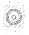
- FIG. 3 is a cross-sectional view taken along the line BB of FIG. It is a partial cross-sectional view which shows the structure of one Embodiment of the tubular reticular formation which constitutes a flexible tube base material.
- a preferred embodiment of an endoscope-type medical device incorporating a flexible tube for an endoscope of the present invention will be described by taking an electronic endoscope as an example.
- the electronic endoscope incorporates the flexible tube for an endoscope of the present invention (hereinafter, the flexible tube for an endoscope may be simply referred to as a "flexible tube”), and this flexible tube is referred to in the body cavity.
- the flexible tube for an endoscope may be simply referred to as a "flexible tube”
- this flexible tube is referred to in the body cavity.
- the electronic endoscope 2 is connected to an insertion unit 3 to be inserted into the body, a main body operation unit 5 connected to the base end portion of the insertion unit 3, and a processor device or a light source device. It is equipped with a universal code 6 to be inserted.
- the insertion section 3 is a flexible tube 3a connected to the main body operation section 5, an angle section 3b connected to the flexible tube 3a, and an imaging device (not shown) for in-vivo imaging connected to the tip of the flexible tube 3b. It is composed of a built-in tip portion 3c.
- the flexible tube 3a which occupies most of the length of the insertion portion 3, has flexibility over almost the entire length thereof, and in particular, the portion to be inserted into the body cavity or the like has a more flexible structure.
- the flexible tube of the present invention has a flexible tubular flexible tube base material and a polymer coating layer that coats the flexible tube base material, and the flexible tube base material and the polymer coating layer. It has a primer layer containing a silane coupling agent between them.
- the flexible tube base material has a spiral tube of a metal strip and a tubular network body in which a metal wire is braided to cover the spiral tube, and the pore ratio of the tubular network body is 2 to 10%. Is. The reason why the flexible tube of the present invention has excellent elasticity, flexibility, and sufficient chemical resistance is not clear, but it is presumed as follows.
- the porosity of the tubular network of the braided structure constituting the flexible tube base material is 2 to 10%, and by having a primer layer containing a silane coupling agent on the flexible tube base material,
- the polymer coating layer is formed, the polymer is densely coated in the pores of the tubular formation and on the surface of the tubular formation (outer circumference of the spiral tube).
- the reaction area between the silane coupling agent and the polymer coating layer is increased, and the silane coupling agent and the polymer coating layer are effectively bonded or adhered to each other.
- the spiral tube and the spiral tube are integrated when the flexible tube is bent, with the polymer coating layer and the spiral tube firmly adhered to each other via the tubular network filled with the polymer at high density.
- the flexible tube of the present invention is excellent in elasticity because of the bending of the flexible tube. It has been clarified as an experimental fact that this improvement in elasticity becomes apparent when the silane coupling agent has an amino group, as shown in Examples described later. Although the reason for this is not clear, the molecular structure of the amino group responsible for the bond or adhesion between the silane coupling agent and the polymer coating layer is the bond or adhesion point with the polymer coating layer because the silane coupling agent has an amino group.
- the porosity of the tubular net body of the braided structure is 2 to 10%, it is possible to sufficiently secure the contact area between the flexible tube base material and the polymer-coated layer and effectively improve the adhesion. It is considered that it can be made, has excellent chemical resistance, and the above-mentioned porosity also imparts sufficient flexibility to the flexible tube base material.
- the flexible tube has a flexible tube base material having a metal as a constituent material as the innermost layer.
- the flexible tube base material 14 is a tubular net body formed by braiding a metal wire around a spiral tube 11 formed by spirally winding a metal strip 11a on the innermost side. It is preferable that the 12 is covered and the bases 13 are fitted to both ends thereof.
- the braided structure of the tubular net body 12 is not particularly limited, and any structure may be used as long as the metal wire is woven by regularly swapping the top and bottom. Examples of the braided structure include knitting (warp / weft), plain weave, twill weave, satin weave, and the like, and twill weave is preferable.
- FIG. 5 is a partial cross-sectional view showing the configuration of one embodiment of the tubular net body 12 having a braided structure formed by twill weaving, and has a bundle having three holdings (a bundle composed of three metal wires 41). It is woven to form a hole 42 between the bundles.
- the porosity of the tubular net 12 formed by braiding a metal wire is 2 to 10%, preferably 3 to 8%, more preferably 3 to 7%, from the viewpoint of elasticity of the flexible tube. ⁇ 6% is more preferable. It is preferable that the surface of the metal constituting the flexible tube base material 14 is subjected to an immobilization treatment in order to prevent corrosion.
- the flexible tube base material 14 has a passivation film on the outer periphery (surface) thereof.
- This mobilization process can be performed by a conventional method.
- a metal surface can be surfaced by immersing it in a solution containing a strong oxidant such as nitric acid, heating it in air (oxygen) or water (steam), or anodizing it in a solution containing an oxidant.
- a passivation film can be formed on the surface.
- the metal constituting the flexible tube base material 14 is preferably stainless steel.
- the spiral tube 11 formed by spirally winding the metal strip 11a on the innermost side and the tubular net body 12 formed by braiding a metal wire are preferably made of stainless steel.
- the surface of stainless steel is usually in a state where chromium and oxygen (O 2 ) are combined to form a passivation film.
- O 2 chromium and oxygen
- a primer layer (not shown) is provided on the outer periphery of the flexible tube base material.
- this primer layer contains a silane coupling agent.
- silane coupling agent used in the present invention, a normal silane coupling agent applicable to the primer layer of a flexible tube for an endoscope can be widely adopted.
- an aminosilane coupling agent (preferably a silane coupling agent having at least one of an unsubstituted amino group and a monosubstituted amino group) is preferable in order to further improve the elasticity.
- the silane coupling agent include, but the present invention is not limited to these, the silane coupling agent used in Examples described later.
- the content of the silane coupling agent in the primer layer is preferably 50% by mass or more, more preferably 70% by mass or more, still more preferably 80% by mass or more, still more preferably 90% by mass or more.
- the primer layer may be a layer made of a silane coupling agent.
- the content of the aminosilane coupling agent in the silane coupling agent is preferably 50% by mass or more, more preferably 70% by mass or more, still more preferably 80% by mass or more, still more preferably 90% by mass or more. ..
- the primer layer may be a layer made of an aminosilane coupling agent.
- the coupling agent is not particularly limited as long as the effect of the present invention is not impaired, and for example, an aluminum coupling agent, a zirconium coupling agent and a titanium coupling agent. Agents are mentioned.
- the thickness of the primer layer is much thinner than that of a normal adhesive layer (in other words, the concept of thickness cannot be recalled). That is, the primer layer containing the silane coupling agent is different from the adhesive layer which requires a certain layer thickness and softness for adhesion between the flexible tube base material and the polymer coating layer.
- the flexible tube of the present invention has a polymer coating layer (a layer containing at least one of a resin and an elastomer) on the outer periphery of a flexible tube base material provided with a primer layer.
- a polymer coating layer a layer containing at least one of a resin and an elastomer
- the outer surface of the polymer coating layer 15 is coated with a top coat layer 16 containing fluorine or the like, which contributes to chemical resistance and the like.
- a top coat layer 16 containing fluorine or the like, which contributes to chemical resistance and the like.
- the polymer coating layer 15 and the top coat layer 16 are drawn thicker than the diameter of the flexible tube base material 14 in order to clearly show the layer structure.
- the polymer coating layer may be a single layer or a multi-layer, and is preferably a multi-layer.
- This polymer coating layer covers the outer peripheral surface of the flexible tube base material having the primer layer described above.
- the polymer coating layer 15 is not a single layer, but covers the inner layer 17 that covers the entire peripheral surface of the flexible tube base material 14 around the axis, and the inner layer 17 that covers the entire peripheral surface of the inner layer 17 around the axis. It is a two-layer structure in which the outer layer 18 is laminated.
- a soft polymer is used as the material of the inner layer 17, and a hard polymer is used as the material of the outer layer 18, but the present invention is not limited to these forms.
- the polymer coating layer is a single layer, and different polymer coating layer forming materials are applied multiple times.
- the polymer-coated layer is a multi-layer.
- the polymer coating layer preferably contains a thermoplastic elastomer
- specific examples of the thermoplastic elastomer include a fluoroelastomer, a polyolefin elastomer, an acrylic elastomer, a styrene elastomer, a polyphenylene oxide elastomer, a polyurethane elastomer, a polyester elastomer, and a polyamide elastomer.
- the thermoplastic elastomer include a fluoroelastomer, a polyolefin elastomer, an acrylic elastomer, a styrene elastomer, a polyphenylene oxide elastomer, a polyurethane elastomer, a polyester elastomer, and a polyamide elastomer.
- the polymer coating layer has a multi-layer structure of two or more layers
- at least the innermost layer is at least one of polyurethane elastomer, polyester elastomer and polyamide elastomer. It preferably contains a thermoplastic elastomer, more preferably a polyurethane elastomer.
- the polymer coating layer of the single layer contains at least one thermoplastic elastomer of a polyurethane elastomer, a polyester elastomer and a polyamide elastomer, and polyurethane.
- the polymer coating layer preferably contains at least one thermoplastic elastomer of polyurethane elastomer, polyester elastomer and polyamide elastomer on the side in contact with the primer layer, and more preferably contains polyurethane elastomer.
- polyurethane elastomer As the polyurethane elastomer used for the polymer coating layer, a normal polyurethane elastomer applicable to the formation of a flexible tube can be adopted.
- This polyurethane elastomer is usually obtained by reacting a polyisocyanate, a polyol and a chain extender.
- the polyurethane elastomer is preferably a random copolymer or a block copolymer composed of a soft segment formed by the reaction of the polymer polyol and the polyisocyanate and a hard segment formed by the reaction of the chain extender and the polyisocyanate, and is a block copolymer. Is more preferable.
- polyether polyurethane elastomer a polyether polyurethane elastomer, a polyester polyurethane elastomer and a polycarbonate polyurethane elastomer are preferable, and a polyether polyurethane elastomer is more preferable.
- the above-mentioned polyether polyurethane elastomer is preferably an elastomer composed of a soft segment formed by a reaction between a polyether polyol and a polyisocyanate and the above-mentioned hard segment, that is, a polyurethane elastomer containing a polyether in the soft segment. It is preferred that this soft segment is free of ester and carbonate bonds.
- the polyester polyurethane elastomer is preferably an elastomer composed of a soft segment formed by the reaction of a polyester polyol and a polyisocyanate and the above-mentioned hard segment, that is, a polyurethane elastomer containing polyester in the soft segment. It is preferred that this soft segment does not contain ether or carbonate bonds.
- the polycarbonate polyurethane elastomer is preferably an elastomer composed of a soft segment formed by the reaction of a polycarbonate polyol and a polyisocyanate and the above-mentioned hard segment, that is, a polyurethane elastomer containing polycarbonate in the soft segment. It is preferred that this soft segment does not contain ether or ester bonds.
- polyisocyanate examples include diphenylmethane diisocyanate, hexamethylene diisocyanate, trizine diisocyanate, 1,5-naphthalene diisocyanate, isophorone diisocyanate, and xylylene diisocyanate.
- polyether polyol examples include polytetramethylene ether glycol, polydimethylene ether glycol, polytrimethylene ether glycol, polypropylene ether glycol, polyhexamethylene ether glycol and polyneopentyl ether glycol.
- the polyester polyol is obtained by a polycondensation reaction between a dicarboxylic acid and a polyol (preferably a diol).
- a diol preferably a diol
- the diol used for producing the polyester polyol include ethylene polyol (for example, ethanediol), propylene polyol (1,3-propanediol), 1,3-butanediol, 1,4-butanediol, and neopentyl polyol.
- 1,5-pentanediol), 1,6-hexanediol, polycaprolactone diol and the like can be mentioned, and these can be used alone or in combination.
- examples of the dicarboxylic acid include adipic acid, sebacic acid, dimer acid and the like, and examples thereof include those used alone or in combination.
- examples of the polycaprolactone diol include Praxel 205, Praxel 205H (trade name, manufactured by Daicel Chemical Industries, Ltd.), TONE 0200, TONE 0201 (trade name, manufactured by Union Carbide), and Praxel 208 (trade name, manufactured by Daicel Chemical Industries, Ltd.). (Manufactured by Kogyo Co., Ltd.) and the like.
- polycarbonate polyol examples include polyethylene carbonate diol, polytetramethylene carbonate diol, and polyhexamethylene carbonate diol.
- Examples of the chain extender include aliphatic linear diols having 2 to 6 carbon atoms such as ethanediol, 1,4-butanediol, and 1,6-hexanediol, and 1,4-bis (hydroxyethoxy). Examples include benzene. Amines such as hexamethylenediamine, isophoronediamine, tolylenediamine, monoethanolamine and the like can also be used in combination as necessary. As the polyurethane elastomer according to the above embodiment, for example, the disclosure of JP-A-2005-015643 can be referred to. The polyurethane elastomer may be used alone or in combination of two or more.
- the polyester elastomer a normal polyester elastomer applicable to the formation of a flexible tube can be used. That is, the polyester elastomer used in the present invention is a copolymer composed of a hard segment made of crystalline polyester and a soft segment made of polyether or polyester. Examples of the hard segment include polybutylene terephthalate, polyethylene terephthalate, and the like. Examples of the soft segment include polytetramethylene glycol, polyalkylene glycol such as polypropylene glycol, bisphenol A ethylene oxide adduct, bisphenol A propylene oxide adduct, polyester such as polycaprolactone, and the like.
- the "polyester elastomer” preferably does not contain a urethane bond in the molecule and does not contain an amide bond.
- One type of polyester elastomer may be used alone, or two or more types may be used in combination.
- polyamide elastomer As the above-mentioned polyamide elastomer, a conventional polyamide elastomer applicable to the formation of a flexible tube can also be used. In the present invention, it is preferable that the polyamide elastomer does not contain a urethane bond and does not contain an ester bond.
- One type of polyamide elastomer may be used alone, or two or more types may be used in combination.
- thermoplastic elastomer used in the present invention include the thermoplastic elastomers (fluoroelastomer-containing elastomer, polyolefin elastomer, polyurethane elastomer, polyester elastomer, and polyamide elastomer) used in Examples described later. Not limited to these.
- the content of the thermoplastic elastomer in the polymer coating layer is 50% by mass or more, and when the polymer coating layer is a multi-layer, the content of the thermoplastic elastomer in the innermost layer is 50% by mass or more. It is preferable, more preferably 70% by mass or more, still more preferably 80% by mass or more, still more preferably 90% by mass or more.
- the polymer coating layer may be a layer made of a thermoplastic elastomer, and when the polymer coating layer is a multi-layer, the innermost layer is a layer made of a thermoplastic elastomer. You may.
- the total content of the polyurethane elastomer, polyester elastomer and polyamide elastomer contained in the thermoplastic elastomer is preferably 50% by mass or more, more preferably 70% by mass or more, still more preferably 80% by mass or more, still more preferably. Is 90% by mass or more, and may be 100% by mass.
- this polymer is particularly effective as long as the effect of the present invention is not impaired.
- vinyl polymers such as acrylic resins and styrene resins and condensation polymers such as polyesters and polyamides can be mentioned.
- the layer other than the innermost layer preferably contains at least one thermoplastic elastomer of polyurethane elastomer, polyester elastomer and polyamide elastomer. These thermoplastic elastomers can be appropriately combined to form a layer having desired physical properties.
- the layers other than the innermost layer more preferably contain a polyester elastomer and a polyamide elastomer from the viewpoint of further enhancing elasticity.
- each of the above elastomers that can be used for the polymer coating layer preferably has a molecular weight of 10,000 to 1,000,000, more preferably 20,000 to 500,000, and particularly preferably 30,000 to 300,000.
- the molecular weight of the elastomer means the weight average molecular weight unless otherwise specified.
- the weight average molecular weight can be measured by GPC as a polystyrene-equivalent molecular weight.
- a GPC device HLC-8220 (trade name, manufactured by Tosoh Corporation) was used, and the eluent used was chloroform for a polyester elastomer, NMP (N-methyl-2-pyrrolidone) for a polyurethane elastomer, and a polyamide elastomer.
- m-cresol / chloroform manufactured by Shonan Wako Junyaku Co., Ltd.
- the column is G3000HXL + G2000HXL (both trade names, manufactured by Tosoh Co., Ltd.)
- the flow rate is 1 mL / min at 23 ° C, and it is detected by RI. ..
- the polymer coating layer 15 is preferably formed to have a substantially uniform thickness in the longitudinal direction (axial direction) of the flexible tube base material 14.
- the thickness of the polymer coating layer 15 is, for example, 0.2 mm to 1.0 mm, and the outer diameter D of the flexible tube 3a is, for example, 11 to 14 mm.
- the thicknesses of the inner layer 17 and the outer layer 18 are formed so that the ratio of the thicknesses of the inner layers 17 and 18 to the total thickness of the polymer coating layer 15 changes in the axial direction of the flexible tube base material 14. ing.
- the thickness of the inner layer 17 is larger than the thickness of the outer layer 18 with respect to the total thickness of the polymer coating layer 15. Is also big. Then, the thickness of the inner layer 17 gradually decreases from one end 14a toward the other end 14b side (base end side) attached to the main body operation unit 5, and on the other end 14b side, the thickness of the outer layer 18 is larger than that of the inner layer 17. It is larger than the thickness of.
- the ratio of the thickness of the inner layer 17 to the one end 14a is the maximum, and the ratio of the thickness of the outer layer 18 to the other end 14b is the maximum.
- Thickness of inner layer 17 The thickness of the outer layer 18 can be, for example, 9: 1 at one end 14a and, for example 1: 9 at the other end 14b. From both ends 14a to 14b, the thicknesses of both layers are changed so that the ratio of the thicknesses of the inner layer 17 and the outer layer 18 is reversed.
- the flexibility of the flexible tube 3a can be changed in the axial direction so that there is a difference in hardness between one end 14a side and the other end 14b side, the one end 14a side is soft and the other end 14b side is hard.
- the thickness ratio at one end is preferably 5:95 to 40:60 (inner layer: outer layer), and the thickness ratio at the other end is 95: 5 to 60:40 (inner layer: outer layer). It is preferable to do so.
- the ratio of the thickness of the inner layer 17 and the outer layer 18 is set to the range of 5:95 to 95: 5, it is possible to precisely control the extrusion amount of the thinner polymer.
- the difference in 100% modulus value which is an index showing the hardness after molding, is preferably 1 MPa or more, and more preferably 3 MPa or more.
- top coat layer 16 In the flexible tube of the present invention, a top coat layer 16 is arranged on the outer periphery of the polymer coating layer 15 as needed.
- the material of the top coat layer is not particularly limited, but urethane paint, acrylic paint, fluorine paint, silicone paint, epoxy paint, polyester paint and the like are applied.
- the main purpose of using the topcoat layer is to protect and polish the surface of the flexible tube, to impart slipperiness, and to impart chemical resistance. Therefore, the topcoat layer preferably has a high elastic modulus, a smooth surface, and excellent chemical resistance.
- a method for manufacturing a flexible tube for an endoscope includes forming a primer layer containing a silane coupling agent and a polymer coating layer in this order on the outer periphery of a flexible tube base material made of a metal. It is sufficient to include forming a primer layer containing a silane coupling agent and a polymer coating layer in this order on at least a part of the outer periphery of the flexible tube base material, and silane coupling also on the inner circumference of the flexible tube base material.
- a primer layer containing an agent and a polymer coating layer may be formed.
- the flexible tube base material can be produced by a usual method except that a metal wire is braided to form a tubular network having a porosity of 2 to 10%.
- a tubular network having a desired porosity can be obtained by controlling the outer diameter, number of holdings, pitch, etc. of the metal wire.
- a flexible tube base material can be obtained by producing and covering the spiral tube with this tubular network.
- a primer layer is first formed on the flexible tube base material.
- a silane coupling agent is dissolved in a solvent to prepare a coating liquid, and this coating liquid is applied to or sprayed on the outer periphery of the flexible tube base material, or the flexible tube base is contained in the coating liquid. It can be formed by forming a coating film on at least the outer periphery of the flexible tube base material by immersing the material, and then drying the coating film by a conventional method (for example, drying at a high temperature of about 100 ° C.). ..
- the solvent used for the coating liquid an alcohol solvent such as methanol and ethanol, a ketone solvent such as acetone and methyl ethyl ketone, an ester solvent such as ethyl acetate, a hydrocarbon solvent such as toluene, or a mixed solution thereof can be used, and these can be used. It is preferable to mix water with the solvent in order to promote the hydrolysis of the silane coupling agent.
- the coating liquid may be prepared to be acidic (for example, pH 1 to 4 at 25 ° C.) or alkaline (for example, pH 9 to 11 at 25 ° C.).
- the content of the silane coupling agent in the coating liquid is not particularly limited, and may be, for example, 0.01 to 2% by mass, 0.02% by mass or more and less than 0.5% by mass, and 0. It may be 03% by mass or more and less than 0.4% by mass.
- the coating liquid may contain a surfactant, a catalyst, etc. in addition to the silane coupling agent, the solvent, and the pH adjuster.
- the coating liquid is more preferably composed of a silane coupling agent and a solvent. In the present invention, there may be a portion not covered with the primer layer in a part of the outer periphery of the flexible tube base material as long as the effect of the present invention is not impaired (that is, a part of the primer layer is defective. May have occurred.).
- the flexible tube base material is degreased and washed with an alkaline solution, a surfactant aqueous solution, an organic solvent, or the like. Further, after the above washing, it is preferable to further wash with water or warm water.
- the formation of the polymer coating layer will be described by taking the case where the polymer coating layer has a two-layer structure as an example.
- the flexible tube having a two-layer structure in which the polymer coating layer is composed of an inner layer and an outer layer is, for example, a first polymer material constituting the inner layer (for example, a polymer material containing a thermoplastic elastomer) and a second polymer constituting the outer layer.
- the material can be obtained by melt-kneading and extruding around the flexible tube base material on which the above-mentioned primer layer is formed, and coating the flexible tube base material.
- An embodiment in which the polymer coating layer is one layer or three or more layers can also be obtained by appropriately changing the layer structure with reference to the following method.
- the continuous molding machine 20 includes a well-known extrusion portion 21 and 22 including a hopper, screws 21a and 22a, a head portion 23 for coating and molding a polymer coating layer 15 on the outer peripheral surface of the flexible tube base material 14, and cooling. It is preferable to use a unit 24, a transport unit 25 (supply drum 28 and a take-up drum 29) for transporting the connecting flexible tube base material 31 to the head portion 23, and a control unit 26 for controlling these. ..
- the head portion 23 is preferably composed of a nipple 32, a die 33, and a support 34 that fixedly supports them.
- a configuration example of such an apparatus for example, the apparatus described in FIGS. 3 to 5 of JP-A-2011-72391 can be used.
- the molding temperature is preferably set in the range of 150 ° C to 300 ° C.
- the temperature of each of the first polymer material 39 and the second polymer material 40 can be increased by heating and adjusting the temperature of the heating portion in the apparatus. In addition, the higher the rotation speed of the screws 21a and 22a, the higher the temperature. , The temperature of each of the first polymer material 39 and the second polymer material 40 can be further increased, and the fluidity of each can be increased.
- the molding thicknesses of the inner layer 17 and the outer layer 18 are each formed. Can be adjusted.
- the process of molding the polymer coating layer 15 on the connected flexible tube base material 31 with the continuous molding machine 20 will be described.
- the continuous molding machine 20 performs the molding step, the first one in a molten state from the extrusion portions 21 and 22
- the polymer material 39 and the second polymer material 40 are extruded into the head portion 23.
- the transport section 25 operates to transport the connected flexible tube base material 31 to the head section 23.
- the extruded portions 21 and 22 are in a state of constantly extruding the first polymer material 39 and the second polymer material 40 and supplying them to the head portion 23, and are extruded from the extruded portions 21 and 22 to the gates 35 and 36.
- the 1-polymer material 39 and the 2nd polymer material 40 merge through the edges and are supplied in an overlapping state through the polymer passage 38 to the molding passage 37. As a result, a two-layer molded polymer coating layer 15 in which the inner layer 17 using the first polymer material 39 and the outer layer 18 using the second polymer material 40 are overlapped is formed.
- the connected flexible tube base material 31 is formed by connecting a plurality of flexible tube base materials 14 (a primer layer is formed on the outer periphery of the flexible tube base material 14), and is formed in the forming passage 37.
- the polymer coating layer 15 is continuously formed on the plurality of flexible tube base materials 14.
- the control unit 26 is used for switching the discharge amounts of the extrusion portions 21 and 22.
- the control unit 26 is based on the ratio of the thickness of one flexible tube base material 14 on the other end 14b side (base end side) to the one end 14a side (tip side) of the next flexible tube base material 14. ), It is preferable to switch the discharge amount of the extrusion portions 21 and 22 so as to be the ratio of the thickness.
- the thickness of the outer layer gradually increases from one end side to the other end side. It is preferable that the extrusion portions 21 and 22 are controlled.
- the connected flexible tube base material 31 on which the polymer coating layer 15 is molded to the end is removed from the continuous molding machine 20, and then the joint member 30 is removed from the flexible tube base material 14, and each flexible tube base material is removed. It is separated into 14. Next, the top coat layer 16 is coated on the polymer coating layer 15 on the separated flexible tube base material 14, and the flexible tube 3a is completed. The completed flexible tube 3a is transported to the assembly process of the electronic endoscope.
- a functional layer may be interposed between the layers constituting the multi-layer.
- the flexible tube of the present invention can be widely applied to endoscopic medical devices.
- it can be applied to an endoscope equipped with a clip or a wire at the tip of the endoscope, or an instrument equipped with a basket or a brush.
- the endoscope-type medical device is a medical device having the above-mentioned endoscope as a basic structure, as well as a remote-controlled medical device, etc., which has a flexible insertion part and is used by being introduced into the body. It means that it includes a wide range of medical or medical equipment.
- the endoscope-type medical device of the present invention has the flexible tube for an endoscope of the present invention incorporated in the insertion portion thereof. That is, the method for manufacturing an endoscopic medical device of the present invention includes incorporating the flexible tube for an endoscope of the present invention into an insertion portion of the endoscopic medical device.
- a solution having a water / ethanol mass ratio of 5/75 was prepared.
- the coupling agent shown in Table 1 below was dissolved in this solution to a concentration of 8.9 g / kg to prepare a coating solution for forming a primer layer.
- Preparation of coating liquid for forming adhesive layer 100 g of polyester polyurethane (trade name: N-2304, manufactured by Nippon Polyurethane Industry Co., Ltd.) and 10 g of polyisocyanate (trade name: Coronate, manufactured by Nippon Polyurethane Industry Co., Ltd.) were dissolved in 1 kg of methyl ethyl ketone to prepare a coating liquid for forming an adhesive layer.
- polyester polyurethane trade name: N-2304, manufactured by Nippon Polyurethane Industry Co., Ltd.
- polyisocyanate trade name: Coronate, manufactured by Nippon Polyurethane Industry Co., Ltd.
- a flexible tube having the structure shown in FIG. 2 was produced.
- the polymer coating layer has a single-layer structure or a two-layer structure as shown in Table 1 below.
- a spiral tube 11 is formed by using a metal strip 11a made of stainless steel, and the spiral tube 11 is covered with a tubular net body 12 made of braided stainless steel fibers (metal wire).
- a tube base material was prepared.
- the wire diameter (outer diameter of the metal wire 41) is set to 0.1 mm and the core material diameter is set to 10.5 mm.
- a tubular net body 12 having a pore ratio shown in Table 1 below was obtained.
- a flexible tube base material was produced by covering the outer periphery of the spiral tube 11 with the tubular net body 12 thus obtained.
- the flexible tube base material has a length of 80 cm and a diameter of 12 mm.
- a passivation layer is formed on the surface of this stainless steel flexible tube by an annealing treatment (heat treatment) at the time of forming the spiral tube 11 and the tubular network 12.
- the adhesive layer forming solution prepared above was uniformly applied to the outer periphery of the stainless steel flexible tube base material, and dried at room temperature for 2 hours. Then, it was further heat-treated at 150 ° C. for 2 hours to prepare a flexible tube base material having an adhesive layer on the outer periphery (resin-coated surface). The thickness of the adhesive layer was about 80 ⁇ m.
- the outer periphery of the flexible tube base material provided with the primer layer or the adhesive layer is extruded and coated with an elastomer as shown in Table 1 below (molding temperature: 200 ° C.), and can be used for endoscopes having a polymer coating layer.
- a flexible tube was made.
- the thickness of the polymer coating layer was 0.4 mm (in the case of a two-layer structure, the combined thickness of the two layers was 0.4 mm).
- the polymer coating layer was two layers (Examples 1 to 39, 44 to 46 and Comparative Examples 1 to 31)
- the 90 ° peel strength was measured by peeling between the flexible tube base material and the polymer coating layer at a constant rate of 2 mm / min in the axial direction along a notch having a width of 1 cm (this measured value X).
- the peel strength was measured with a force gauge (unit: N / cm).
- the 90 ° peel strength was measured in the same manner using a flexible tube for an endoscope that was not immersed in an aqueous solution of peracetic acid (measured value Y). For all flexible tubes, 90 ° peel strength was measured under the same conditions.
- the ratio of the measured value X to the measured value Y (%, 100 ⁇ X / Y) was obtained and evaluated by applying it to the following criteria. "C" or higher is a pass.
- Ratio is 80% or more
- B Ratio is 60% or more and less than 80%
- C Ratio is 40% or more and less than 60%
- D Ratio is less than 40% (Polymer coating layer is peeled off during immersion in peracetic acid aqueous solution (Including those that have been lost)
- the polymers used for the polymer coating layer are as follows.
- PU1 Polyester polyurethane elastomer (trade name: Pandex T-8185, manufactured by DIC Corporation)
- PU2 Polyester polyurethane elastomer (trade name: Miractran E380, manufactured by Nippon Polyurethane Industry Co., Ltd.)
- PU3 Polyester Polyurethane Elastomer (Product name: Miractran E480, manufactured by Nippon Polyurethane Industry Co., Ltd.)
- PU4 Polycarbonate Polyurethane Elastomer (Product name: Pandex T-9280, manufactured by DIC Corporation)
- PE1 Polyester elastomer (trade name: Perprene P-40B, manufactured by Toyobo Co., Ltd.)
- PA1 PA1: PA1: Polyamide elastomer (trade name: Pevacs 4533, manufactured by Arkema)
- Fluorine-containing elastomer Daiel T-530 (trade name), Polyolefin elastomer manufactured by Daikin Industries, Ltd .: Zelas MC707 (trade name), manufactured by Mitsubishi Chemical Corporation
- the coupling agents used for the primer layer are as follows.
- A-1 Aluminum sec-butoxide (trade name: ASBD, manufactured by Kawaken Fine Chemicals Co., Ltd.)
- A-2) Aluminum Tris Acetylacetone (Product name: Organix AL-3100, manufactured by Matsumoto Fine Chemical Co., Ltd.)
- A-3) Aluminum Bisethylacetate Acetate Monoacetylacetone (Product name: Organix AL-3200, manufactured by Matsumoto Fine Chemical Co., Ltd.)
- A-5) Aluminum Octadecylacetacetate diisopropilate (trade name: Plenact AL-M, manufactured by Ajinomoto Fine Techno Co., Ltd.)
- Z-1 Zirconium Tetra n-Propoxide (Product Name: Organix ZA-45, manufactured by Matsumoto Fine Chemical Co., Ltd.)
- Z-2 Zirconium tetra n-butoxide (trade name: Olgatics ZA-65, manufactured by Matsumoto Fine Chemical Co., Ltd.)
- Z-3 Zirconium tetraacetylacetonate (trade name: Olgatics ZC-150, manufactured by Matsumoto Fine Chemical Co., Ltd.)
- Z-4 Zirconium Lactate Ammonium Salt (Product Name: Olga Chix ZC-300, manufactured by Matsumoto Fine Chemical Co., Ltd.)
- Z-5) Zirconium stearate tri-n-butoxide (trade name: Organix ZC-320, manufactured by Matsumoto Fine Chemicals)
- T-1 Tetra n-butyl titanate (trade name: Organix TA-21, manufactured by Matsumoto Fine Chemical Co., Ltd.)
- T-2 n-Butyl titanate dimer (trade name: Organix TA-23, manufactured by Matsumoto Fine Chemical Co., Ltd.)
- T-3 Isopropyltriisostearoyl titanate (trade name: Plenact TTS, manufactured by Ajinomoto Fine-Techno)
- T-4 Dioctylvis (ditridecyl) phosphate titanate (trade name: Plenact 46B, manufactured by Ajinomoto Fine-Techno)
- T-5 Diisopropylbis (Dioctylpyrophosphate) titanate (trade name: Plenact 38S, manufactured by Ajinomoto Fine-Techno)
- the flexible tubes of Comparative Examples 1, 4, 7, 10 and 13 having a porosity below the lower limit specified in the present invention were inferior in flexibility.
- the flexible tubes of Comparative Examples 2, 3, 5, 6, 8, 9, 11, 12, 14 and 15 in which the porosity exceeds the upper limit specified in the present invention were inferior in elasticity.
- the flexible tubes of Comparative Examples 16 to 30 have a primer layer made of a coupling agent other than the silane coupling agent.
- the flexible pipes of Comparative Examples 16 to 30 had a porosity satisfying the provisions of the present invention, but were inferior in elasticity.
- the flexible tube of Comparative Example 31 having an adhesive layer instead of the primer layer was inferior in elasticity and chemical resistance.
- the flexible tubes (Examples 1 to 50) of the present invention are excellent in elasticity, excellent in flexibility, and have sufficient chemical resistance. From the comparison between the results of Examples 1 to 11 and the results of Examples 12 to 39, when the aminosilane coupling agent is used as the silane coupling agent, the porosity is controlled to raise the elasticity to a higher level. It turns out that it can be enhanced.
Abstract
Provided are a flexible tube for an endoscope which has excellent resilience, excellent flexibility, and sufficient chemical resistance, an endoscope-type medical device which comprises the flexible tube, a method for producing the flexible tube, and a method for producing the endoscope-type medical device. The flexible tube for an endoscope comprises a tubular flexible tube base material which has flexibility and a polymer covering layer which covers the flexible tube base material, wherein the flexible tube base material comprises a helical tube which is made from a metal strip and a tubular mesh which covers the helical tube and which is formed by braiding a metal wire, the tubular mesh has a porosity of 2-10%, the flexible tube comprising a primer layer which is between the flexible tube base material and the polymer covering layer and which contains a silane coupling agent.
Description
本発明は、内視鏡用可撓管、内視鏡型医療機器、及びこれらの製造方法に関する。
The present invention relates to a flexible tube for an endoscope, an endoscopic medical device, and a method for manufacturing these.
内視鏡は、患者の体腔内、消化管内又は食道等を観察するための医療用機器である。体内に挿入して用いるため、臓器に傷をつけず、患者に痛みないし違和感を与えないものが望まれる。そのような要請から、内視鏡の挿入部(体腔内に挿入される構造部)を構成する可撓管(内視鏡用可撓管)には、柔らかく屈曲する金属帯片を螺旋状に巻いて形成された螺旋管及びこの螺旋管を覆う筒状網体を有する可撓管基材が採用されている。さらに、可撓管基材の周囲は柔軟な樹脂又はエラストマーで被覆され、この樹脂又はエラストマー被覆層が必要によりトップコート層で被覆されて、食道、消化管又は体腔等の内表面に刺激ないし傷を与えない工夫がなされている。
An endoscope is a medical device for observing a patient's body cavity, digestive tract, esophagus, etc. Since it is inserted into the body and used, it is desired that it does not damage the organs and does not cause pain or discomfort to the patient. In response to such a request, the flexible tube (flexible tube for endoscope) that constitutes the insertion part (structural part inserted into the body cavity) of the endoscope is spirally formed with a metal strip that bends softly. A flexible tube base material having a spiral tube formed by winding and a tubular net body covering the spiral tube is adopted. In addition, the perimeter of the flexible tube substrate is coated with a flexible resin or elastomer, which is optionally coated with a topcoat layer to irritate or scratch the inner surface of the esophagus, gastrointestinal tract, body cavity, etc. Has been devised so as not to give.
この可撓管には、体内で滑らかに移動させるために、高い弾発性が求められる。可撓管の弾発性を高めることにより、体内の屈曲部を通過した可撓管が直線状に戻りやすく、検査時の被検者の負担をより軽減することができる。このような要求に応える技術として、例えば、特許文献1には、金属を構成材料とする可撓管基材とこの可撓管基材の外周を覆う樹脂被覆層とを有し、これらの可撓管基材と樹脂被覆層との間に特定の構造を有するアミノシランカップリング剤を含むプライマー層を有し、上記樹脂被覆層が少なくともプライマー層と接する側にポリウレタンエラストマーを含む、内視鏡用可撓管が記載されている。
This flexible tube is required to have high elasticity in order to move smoothly in the body. By increasing the elasticity of the flexible tube, the flexible tube that has passed through the bent portion in the body can easily return to a straight line, and the burden on the subject at the time of inspection can be further reduced. As a technique for meeting such a demand, for example, Patent Document 1 has a flexible tube base material made of a metal and a resin coating layer covering the outer periphery of the flexible tube base material, and these are possible. For endoscopes, which has a primer layer containing an aminosilane coupling agent having a specific structure between the flexible tube base material and the resin coating layer, and contains a polyurethane elastomer at least on the side where the resin coating layer is in contact with the primer layer. Flexible tubes are described.
また鉗子口及び照明窓等が配置された、内視鏡用可撓管の先端部を患部等までスムーズに、かつ確実に届けてその詳細な情報を得たり、高精度に処置したりするためには、内視鏡用可撓管の可撓性を高めて操作性を向上させることが必要である。他方、内視鏡は繰り返し使用されるため、使用のたびに洗浄し、薬品を用いて消毒する必要がある。そのため、内視鏡用可撓管には十分な耐薬品性を有することも求められる。
In addition, in order to smoothly and surely deliver the tip of the flexible tube for endoscopes, which has a forceps opening and an illumination window, to the affected area, etc., to obtain detailed information and to perform treatment with high accuracy. It is necessary to increase the flexibility of the flexible tube for an endoscope to improve operability. On the other hand, since endoscopes are used repeatedly, they need to be washed and disinfected with chemicals after each use. Therefore, the flexible tube for an endoscope is also required to have sufficient chemical resistance.
本発明は、弾発性に優れ、可撓性にも優れ、また十分な耐薬品性を有する内視鏡用可撓管、この内視鏡用可撓管を備えた内視鏡型医療機器を提供することを課題とする。また本発明は、上記内視鏡用可撓管の製造方法及び上記内視鏡型医療機器の製造方法を提供することを課題とする。
The present invention is a flexible tube for an endoscope having excellent elasticity, flexibility, and sufficient chemical resistance, and an endoscopic medical device provided with the flexible tube for an endoscope. The challenge is to provide. Another object of the present invention is to provide a method for manufacturing a flexible tube for an endoscope and a method for manufacturing an endoscope-type medical device.
本発明者らが、シランカップリング剤を含むプライマー層を有する内視鏡用可撓管について検討を重ねた結果、弾発性のさらなる向上には、可撓管基材の構造、特に筒状網体の構造が重要であることが分かってきた。本発明者らは、可撓管基材を構成する筒状網体として金属線を編組してなる網体を用い、この筒状網体の空孔率を制御することにより、得られる可撓管において、弾発性を高度なレベルへと高めることができること、また、この可撓管が可撓性にも優れ、十分な耐薬品性を有することを見出した。本発明は、これらの知見に基づきさらに検討を重ね、完成させるに至ったものである。
As a result of repeated studies by the present inventors on a flexible tube for an endoscope having a primer layer containing a silane coupling agent, the structure of the flexible tube base material, particularly a tubular shape, can be further improved in elasticity. It has become clear that the structure of the network is important. The present inventors use a mesh body made by braiding a metal wire as a tubular net body constituting a flexible tube base material, and control the porosity of the tubular net body to obtain flexibility. It has been found that the elasticity of the tube can be increased to a high level, and that the flexible tube has excellent flexibility and sufficient chemical resistance. The present invention has been further studied and completed based on these findings.
本発明の上記課題は下記の手段により解決された。
<1>
可撓性を有する筒状の可撓管基材と、可撓管基材を被覆するポリマー被覆層とを有する内視鏡用可撓管であって、
上記可撓管基材が金属帯片の螺旋管と、螺旋管を被覆する、金属線を編組してなる筒状網体とを有し、筒状網体の空孔率が2~10%であり、
上記可撓管基材と上記ポリマー被覆層との間にシランカップリング剤を含むプライマー層を有する、内視鏡用可撓管。
<2>
上記シランカップリング剤がアミノシランカップリング剤を含む、<1>に記載の内視鏡用可撓管。
<3>
上記ポリマー被覆層が熱可塑性エラストマーを含む、<1>又は<2>に記載の内視鏡用可撓管。
<4>
上記ポリマー被覆層が、少なくともプライマー層と接する側に、ポリウレタンエラストマー、ポリエステルエラストマー及びポリアミドエラストマーの少なくとも1種の熱可塑性エラストマーを含む、<1>~<3>のいずれか1つに記載の内視鏡用可撓管。
<5>
上記可撓管基材を構成する金属がステンレススチールである、<1>~<4>のいずれか1つに記載の内視鏡用可撓管。
<6>
上記可撓管基材を構成する金属が表面に不動態皮膜を有する、<1>~<5>のいずれか1つに記載の内視鏡用可撓管。
<7>
<1>~<6>のいずれか1つに記載の内視鏡用可撓管を有する内視鏡型医療機器。
<8>
金属を構成材料とする可撓管基材の外周に、シランカップリング剤を含むプライマー層とポリマー被覆層とをこの順に形成することを含み、
上記可撓管基材が、金属帯片の螺旋管と、螺旋管を被覆する、金属線を編組してなる筒状網体とを有し、筒状網体の空孔率が2~10%である、<1>~<6>のいずれか1つに記載の内視鏡用可撓管の製造方法。
<9>
<1>~<6>のいずれか1つに記載の内視鏡用可撓管を内視鏡型医療機器の挿入部に組み込むことを含む、内視鏡型医療機器の製造方法。 The above-mentioned problems of the present invention have been solved by the following means.
<1>
A flexible tube for an endoscope having a flexible tubular flexible tube base material and a polymer coating layer covering the flexible tube base material.
The flexible tube base material has a spiral tube of a metal strip and a tubular network body in which a metal wire is braided to cover the spiral tube, and the pore ratio of the tubular network body is 2 to 10%. And
A flexible tube for an endoscope having a primer layer containing a silane coupling agent between the flexible tube base material and the polymer coating layer.
<2>
The flexible tube for an endoscope according to <1>, wherein the silane coupling agent contains an aminosilane coupling agent.
<3>
The flexible tube for an endoscope according to <1> or <2>, wherein the polymer coating layer contains a thermoplastic elastomer.
<4>
The internal vision according to any one of <1> to <3>, wherein the polymer coating layer contains at least one thermoplastic elastomer of polyurethane elastomer, polyester elastomer and polyamide elastomer on the side in contact with the primer layer. Flexible tube for mirror.
<5>
The flexible tube for an endoscope according to any one of <1> to <4>, wherein the metal constituting the flexible tube base material is stainless steel.
<6>
The flexible tube for an endoscope according to any one of <1> to <5>, wherein the metal constituting the flexible tube base material has a passivation film on the surface.
<7>
An endoscopic medical device having a flexible tube for an endoscope according to any one of <1> to <6>.
<8>
It includes forming a primer layer containing a silane coupling agent and a polymer coating layer in this order on the outer periphery of a flexible tube base material made of a metal.
The flexible tube base material has a spiral tube of a metal strip and a tubular network body in which a metal wire is braided to cover the spiral tube, and the pore ratio of the tubular network body is 2 to 10. %, The method for manufacturing a flexible tube for an endoscope according to any one of <1> to <6>.
<9>
A method for manufacturing an endoscopic medical device, which comprises incorporating the flexible tube for an endoscope according to any one of <1> to <6> into an insertion portion of the endoscopic medical device.
<1>
可撓性を有する筒状の可撓管基材と、可撓管基材を被覆するポリマー被覆層とを有する内視鏡用可撓管であって、
上記可撓管基材が金属帯片の螺旋管と、螺旋管を被覆する、金属線を編組してなる筒状網体とを有し、筒状網体の空孔率が2~10%であり、
上記可撓管基材と上記ポリマー被覆層との間にシランカップリング剤を含むプライマー層を有する、内視鏡用可撓管。
<2>
上記シランカップリング剤がアミノシランカップリング剤を含む、<1>に記載の内視鏡用可撓管。
<3>
上記ポリマー被覆層が熱可塑性エラストマーを含む、<1>又は<2>に記載の内視鏡用可撓管。
<4>
上記ポリマー被覆層が、少なくともプライマー層と接する側に、ポリウレタンエラストマー、ポリエステルエラストマー及びポリアミドエラストマーの少なくとも1種の熱可塑性エラストマーを含む、<1>~<3>のいずれか1つに記載の内視鏡用可撓管。
<5>
上記可撓管基材を構成する金属がステンレススチールである、<1>~<4>のいずれか1つに記載の内視鏡用可撓管。
<6>
上記可撓管基材を構成する金属が表面に不動態皮膜を有する、<1>~<5>のいずれか1つに記載の内視鏡用可撓管。
<7>
<1>~<6>のいずれか1つに記載の内視鏡用可撓管を有する内視鏡型医療機器。
<8>
金属を構成材料とする可撓管基材の外周に、シランカップリング剤を含むプライマー層とポリマー被覆層とをこの順に形成することを含み、
上記可撓管基材が、金属帯片の螺旋管と、螺旋管を被覆する、金属線を編組してなる筒状網体とを有し、筒状網体の空孔率が2~10%である、<1>~<6>のいずれか1つに記載の内視鏡用可撓管の製造方法。
<9>
<1>~<6>のいずれか1つに記載の内視鏡用可撓管を内視鏡型医療機器の挿入部に組み込むことを含む、内視鏡型医療機器の製造方法。 The above-mentioned problems of the present invention have been solved by the following means.
<1>
A flexible tube for an endoscope having a flexible tubular flexible tube base material and a polymer coating layer covering the flexible tube base material.
The flexible tube base material has a spiral tube of a metal strip and a tubular network body in which a metal wire is braided to cover the spiral tube, and the pore ratio of the tubular network body is 2 to 10%. And
A flexible tube for an endoscope having a primer layer containing a silane coupling agent between the flexible tube base material and the polymer coating layer.
<2>
The flexible tube for an endoscope according to <1>, wherein the silane coupling agent contains an aminosilane coupling agent.
<3>
The flexible tube for an endoscope according to <1> or <2>, wherein the polymer coating layer contains a thermoplastic elastomer.
<4>
The internal vision according to any one of <1> to <3>, wherein the polymer coating layer contains at least one thermoplastic elastomer of polyurethane elastomer, polyester elastomer and polyamide elastomer on the side in contact with the primer layer. Flexible tube for mirror.
<5>
The flexible tube for an endoscope according to any one of <1> to <4>, wherein the metal constituting the flexible tube base material is stainless steel.
<6>
The flexible tube for an endoscope according to any one of <1> to <5>, wherein the metal constituting the flexible tube base material has a passivation film on the surface.
<7>
An endoscopic medical device having a flexible tube for an endoscope according to any one of <1> to <6>.
<8>
It includes forming a primer layer containing a silane coupling agent and a polymer coating layer in this order on the outer periphery of a flexible tube base material made of a metal.
The flexible tube base material has a spiral tube of a metal strip and a tubular network body in which a metal wire is braided to cover the spiral tube, and the pore ratio of the tubular network body is 2 to 10. %, The method for manufacturing a flexible tube for an endoscope according to any one of <1> to <6>.
<9>
A method for manufacturing an endoscopic medical device, which comprises incorporating the flexible tube for an endoscope according to any one of <1> to <6> into an insertion portion of the endoscopic medical device.
本明細書において、「空孔率」とは、後記実施例に記載の算出方法により得られる値である。
また、本明細書の説明において、「~」とは、その前後に記載される数値を下限値及び上限値として含む意味で使用される。 In the present specification, the "porosity" is a value obtained by the calculation method described in Examples described later.
Further, in the description of the present specification, "-" is used in the meaning of including the numerical values described before and after it as the lower limit value and the upper limit value.
本発明の内視鏡用可撓管は、弾発性に優れ、可撓性にも優れ、また十分な耐薬品性を有する。
本発明の内視鏡型医療機器は、体内に挿入される構造部である可撓管が、弾発性に優れ、可撓性にも優れ、また十分な耐薬品性を有する。したがって、本発明の内視鏡型医療機器は使用時における被検者の負担をより軽減することができ、また高精度の診察を繰返し行うことができる。
本発明の内視鏡用可撓管の製造方法によれば、弾発性に優れ、可撓性にも優れ、また十分な耐薬品性を有する内視鏡用可撓管を得ることができる。
本発明の内視鏡型医療機器の製造方法によれば、この機器を構成する可撓管を、弾発性に優れ、可撓性にも優れ、また十分な耐薬品性を有するものとすることができる。したがって、本発明の内視鏡型医療機器の製造方法により、使用時における被検者の負担がより軽減され、また高精度の診察を繰返し行うことができる内視鏡型医療機器を得ることができる。 The flexible tube for an endoscope of the present invention has excellent elasticity, excellent flexibility, and sufficient chemical resistance.
In the endoscopic medical device of the present invention, the flexible tube, which is a structural part inserted into the body, has excellent elasticity, excellent flexibility, and sufficient chemical resistance. Therefore, the endoscopic medical device of the present invention can further reduce the burden on the subject during use, and can repeatedly perform high-precision examinations.
According to the method for manufacturing a flexible tube for an endoscope of the present invention, a flexible tube for an endoscope having excellent elasticity, excellent flexibility, and sufficient chemical resistance can be obtained. ..
According to the method for manufacturing an endoscopic medical device of the present invention, the flexible tube constituting this device shall have excellent elasticity, excellent flexibility, and sufficient chemical resistance. be able to. Therefore, according to the method for manufacturing an endoscopic medical device of the present invention, it is possible to obtain an endoscopic medical device that can further reduce the burden on the subject during use and can repeatedly perform high-precision examinations. can.
<内視鏡>
本発明の内視鏡用可撓管が組み込まれた内視鏡型医療機器の好ましい実施形態について、電子内視鏡を例に説明する。電子内視鏡は、本発明の内視鏡用可撓管が組み込まれ(以下、内視鏡用可撓管を単に「可撓管」と称することもある)、この可撓管を体腔内、消化管内又は食道等に挿入して体内を観察等する医療機器として用いられる。図1に示した例において、電子内視鏡2は、体内に挿入される挿入部3と、挿入部3の基端部分に連設された本体操作部5と、プロセッサ装置又は光源装置に接続されるユニバーサルコード6とを備えている。挿入部3は、本体操作部5に連設される可撓管3aと、そこに連設されるアングル部3bと、その先端に連設され、体内撮影用の撮像装置(図示せず)が内蔵された先端部3cとから構成される。挿入部3の大半の長さを占める可撓管3aは、そのほぼ全長にわたって可撓性を有し、特に体腔等の内部に挿入される部位はより可撓性に富む構造となっている。 <Endoscope>
A preferred embodiment of an endoscope-type medical device incorporating a flexible tube for an endoscope of the present invention will be described by taking an electronic endoscope as an example. The electronic endoscope incorporates the flexible tube for an endoscope of the present invention (hereinafter, the flexible tube for an endoscope may be simply referred to as a "flexible tube"), and this flexible tube is referred to in the body cavity. , Used as a medical device for observing the inside of the body by inserting it into the gastrointestinal tract or the esophagus. In the example shown in FIG. 1, theelectronic endoscope 2 is connected to an insertion unit 3 to be inserted into the body, a main body operation unit 5 connected to the base end portion of the insertion unit 3, and a processor device or a light source device. It is equipped with a universal code 6 to be inserted. The insertion section 3 is a flexible tube 3a connected to the main body operation section 5, an angle section 3b connected to the flexible tube 3a, and an imaging device (not shown) for in-vivo imaging connected to the tip of the flexible tube 3b. It is composed of a built-in tip portion 3c. The flexible tube 3a, which occupies most of the length of the insertion portion 3, has flexibility over almost the entire length thereof, and in particular, the portion to be inserted into the body cavity or the like has a more flexible structure.
本発明の内視鏡用可撓管が組み込まれた内視鏡型医療機器の好ましい実施形態について、電子内視鏡を例に説明する。電子内視鏡は、本発明の内視鏡用可撓管が組み込まれ(以下、内視鏡用可撓管を単に「可撓管」と称することもある)、この可撓管を体腔内、消化管内又は食道等に挿入して体内を観察等する医療機器として用いられる。図1に示した例において、電子内視鏡2は、体内に挿入される挿入部3と、挿入部3の基端部分に連設された本体操作部5と、プロセッサ装置又は光源装置に接続されるユニバーサルコード6とを備えている。挿入部3は、本体操作部5に連設される可撓管3aと、そこに連設されるアングル部3bと、その先端に連設され、体内撮影用の撮像装置(図示せず)が内蔵された先端部3cとから構成される。挿入部3の大半の長さを占める可撓管3aは、そのほぼ全長にわたって可撓性を有し、特に体腔等の内部に挿入される部位はより可撓性に富む構造となっている。 <Endoscope>
A preferred embodiment of an endoscope-type medical device incorporating a flexible tube for an endoscope of the present invention will be described by taking an electronic endoscope as an example. The electronic endoscope incorporates the flexible tube for an endoscope of the present invention (hereinafter, the flexible tube for an endoscope may be simply referred to as a "flexible tube"), and this flexible tube is referred to in the body cavity. , Used as a medical device for observing the inside of the body by inserting it into the gastrointestinal tract or the esophagus. In the example shown in FIG. 1, the
<内視鏡用可撓管>
本発明の可撓管は、可撓性を有する筒状の可撓管基材と、可撓管基材を被覆するポリマー被覆層とを有し、可撓管基材とポリマー被覆層との間にシランカップリング剤を含むプライマー層を有する。上記可撓管基材は金属帯片の螺旋管と、螺旋管を被覆する、金属線を編組してなる筒状網体とを有し、筒状網体の空孔率は2~10%である。
本発明の可撓管が弾発性に優れ、可撓性にも優れ、十分な耐薬品性を有する理由は定かではないが以下のように推定される。すなわち、可撓管基材を構成する編組構造の筒状網体の空孔率は2~10%であり、この可撓管基材上にシランカップリング剤を含むプライマー層を有することにより、ポリマー被覆層形成時に筒状網体の空孔中及び筒状網体の表面(螺旋菅の外周)にポリマーが高密度で被覆される。これにより、シランカップリング剤とポリマー被覆層との反応面積が増大し、シランカップリング剤とポリマー被覆層とが効果的に結合ないし密着する。このようにして、ポリマー被覆層と螺旋管とがポリマーが高密度で充填された筒状網体を介して強固に密着した状態で、可撓管屈曲時に螺旋管と筒状網体とが一体となって屈曲することなどが、本発明の可撓管が弾発性に優れる要因であると考えられる。この弾発性の向上は、シランカップリング剤がアミノ基を有する場合により顕在化することが、後述する実施例に示す通り、実験事実として明らかとなっている。この理由も定かではないが、シランカップリング剤がアミノ基を有することで、シランカップリング剤とポリマー被覆層との結合ないし接着を担うアミノ基の分子構造がポリマー被覆層との結合ないし接着点の増加に寄与することが一因と考えられる。一方、編組構造の筒状網体の空孔率が2~10%であることで、可撓管基材とポリマー被覆層間の接触面積を十分に確保して密着性を効果的に高めることができ、耐薬品性にも優れ、かつ、上記の空孔率は可撓管基材に十分な可撓性も付与するものと考えられる。 <Flexible tube for endoscope>
The flexible tube of the present invention has a flexible tubular flexible tube base material and a polymer coating layer that coats the flexible tube base material, and the flexible tube base material and the polymer coating layer. It has a primer layer containing a silane coupling agent between them. The flexible tube base material has a spiral tube of a metal strip and a tubular network body in which a metal wire is braided to cover the spiral tube, and the pore ratio of the tubular network body is 2 to 10%. Is.
The reason why the flexible tube of the present invention has excellent elasticity, flexibility, and sufficient chemical resistance is not clear, but it is presumed as follows. That is, the porosity of the tubular network of the braided structure constituting the flexible tube base material is 2 to 10%, and by having a primer layer containing a silane coupling agent on the flexible tube base material, When the polymer coating layer is formed, the polymer is densely coated in the pores of the tubular formation and on the surface of the tubular formation (outer circumference of the spiral tube). As a result, the reaction area between the silane coupling agent and the polymer coating layer is increased, and the silane coupling agent and the polymer coating layer are effectively bonded or adhered to each other. In this way, the spiral tube and the spiral tube are integrated when the flexible tube is bent, with the polymer coating layer and the spiral tube firmly adhered to each other via the tubular network filled with the polymer at high density. It is considered that the flexible tube of the present invention is excellent in elasticity because of the bending of the flexible tube. It has been clarified as an experimental fact that this improvement in elasticity becomes apparent when the silane coupling agent has an amino group, as shown in Examples described later. Although the reason for this is not clear, the molecular structure of the amino group responsible for the bond or adhesion between the silane coupling agent and the polymer coating layer is the bond or adhesion point with the polymer coating layer because the silane coupling agent has an amino group. It is considered that one of the factors is that it contributes to the increase of. On the other hand, since the porosity of the tubular net body of the braided structure is 2 to 10%, it is possible to sufficiently secure the contact area between the flexible tube base material and the polymer-coated layer and effectively improve the adhesion. It is considered that it can be made, has excellent chemical resistance, and the above-mentioned porosity also imparts sufficient flexibility to the flexible tube base material.
(可撓管基材)
可撓管は、最内層として金属を構成材料とする可撓管基材を有する。
図2に示すように、可撓管基材14は、最内側に金属帯片11aを螺旋状に巻回することにより形成される螺旋管11に、金属線を編組してなる筒状網体12を被覆して両端に口金13をそれぞれ嵌合した形態とすることが好ましい。筒状網体12の編組構造は特に限定されず、金属線を、規則的に上下を入れ替えて編み込んだ構造であればよい。編組構造としては、例えば、メリヤス編み(経/緯)、平織り、綾織り及び朱子織り等が挙げられ、なかでも綾織りが好ましい。図5は、綾織りにより編組構造を形成してなる筒状網体12の一実施形態の構成を示す部分断面図であり、持ち数3の束(3本の金属線41からなる束)を編み込み、束と束との間に空孔42を形成している。
金属線を編組してなる筒状網体12の空孔率は2~10%であり、可撓管の弾発性の点から3~8%が好ましく、3~7%がより好ましく、3~6%が更に好ましい。
可撓管基材14を構成する金属は、腐蝕を防ぐために、その表面に不動態化処理が施されていることが好ましい。すなわち、可撓管基材14はその外周(表面)に不動態皮膜を有することが好ましい。この不動態化処理は常法により行うことができる。例えば、硝酸などの強力な酸化剤を含む溶液に浸漬したり、空気(酸素)中もしくは水(水蒸気)中で加熱したり、酸化剤を含む溶液中で陽極酸化したりすることにより、金属表面に不動態皮膜を形成することができる。
可撓管基材14を構成する金属は、ステンレススチールが好ましい。最内側に金属帯片11aを螺旋状に巻回することにより形成される螺旋管11および金属線を編組してなる筒状網体12は、ステンレススチールで構成されることが好ましい。ステンレススチール表面は通常、クロムと酸素(O2)が結合して不動態皮膜が形成された状態にある。しかし、可撓管基材14の構成材料としてステンレススチールを使用する場合であっても、ステンレススチール表面全体に、より均一な不動態皮膜をより確実に形成させるために、ステンレススチールに上述した不動態化処理を施すことが好ましい。 (Flexible tube base material)
The flexible tube has a flexible tube base material having a metal as a constituent material as the innermost layer.
As shown in FIG. 2, the flexibletube base material 14 is a tubular net body formed by braiding a metal wire around a spiral tube 11 formed by spirally winding a metal strip 11a on the innermost side. It is preferable that the 12 is covered and the bases 13 are fitted to both ends thereof. The braided structure of the tubular net body 12 is not particularly limited, and any structure may be used as long as the metal wire is woven by regularly swapping the top and bottom. Examples of the braided structure include knitting (warp / weft), plain weave, twill weave, satin weave, and the like, and twill weave is preferable. FIG. 5 is a partial cross-sectional view showing the configuration of one embodiment of the tubular net body 12 having a braided structure formed by twill weaving, and has a bundle having three holdings (a bundle composed of three metal wires 41). It is woven to form a hole 42 between the bundles.
The porosity of the tubular net 12 formed by braiding a metal wire is 2 to 10%, preferably 3 to 8%, more preferably 3 to 7%, from the viewpoint of elasticity of the flexible tube. ~ 6% is more preferable.
It is preferable that the surface of the metal constituting the flexibletube base material 14 is subjected to an immobilization treatment in order to prevent corrosion. That is, it is preferable that the flexible tube base material 14 has a passivation film on the outer periphery (surface) thereof. This mobilization process can be performed by a conventional method. For example, a metal surface can be surfaced by immersing it in a solution containing a strong oxidant such as nitric acid, heating it in air (oxygen) or water (steam), or anodizing it in a solution containing an oxidant. A passivation film can be formed on the surface.
The metal constituting the flexibletube base material 14 is preferably stainless steel. The spiral tube 11 formed by spirally winding the metal strip 11a on the innermost side and the tubular net body 12 formed by braiding a metal wire are preferably made of stainless steel. The surface of stainless steel is usually in a state where chromium and oxygen (O 2 ) are combined to form a passivation film. However, even when stainless steel is used as the constituent material of the flexible tube base material 14, in order to more reliably form a more uniform passivation film on the entire surface of the stainless steel, the above-mentioned inconvenience described above. It is preferable to perform a passivation treatment.
可撓管は、最内層として金属を構成材料とする可撓管基材を有する。
図2に示すように、可撓管基材14は、最内側に金属帯片11aを螺旋状に巻回することにより形成される螺旋管11に、金属線を編組してなる筒状網体12を被覆して両端に口金13をそれぞれ嵌合した形態とすることが好ましい。筒状網体12の編組構造は特に限定されず、金属線を、規則的に上下を入れ替えて編み込んだ構造であればよい。編組構造としては、例えば、メリヤス編み(経/緯)、平織り、綾織り及び朱子織り等が挙げられ、なかでも綾織りが好ましい。図5は、綾織りにより編組構造を形成してなる筒状網体12の一実施形態の構成を示す部分断面図であり、持ち数3の束(3本の金属線41からなる束)を編み込み、束と束との間に空孔42を形成している。
金属線を編組してなる筒状網体12の空孔率は2~10%であり、可撓管の弾発性の点から3~8%が好ましく、3~7%がより好ましく、3~6%が更に好ましい。
可撓管基材14を構成する金属は、腐蝕を防ぐために、その表面に不動態化処理が施されていることが好ましい。すなわち、可撓管基材14はその外周(表面)に不動態皮膜を有することが好ましい。この不動態化処理は常法により行うことができる。例えば、硝酸などの強力な酸化剤を含む溶液に浸漬したり、空気(酸素)中もしくは水(水蒸気)中で加熱したり、酸化剤を含む溶液中で陽極酸化したりすることにより、金属表面に不動態皮膜を形成することができる。
可撓管基材14を構成する金属は、ステンレススチールが好ましい。最内側に金属帯片11aを螺旋状に巻回することにより形成される螺旋管11および金属線を編組してなる筒状網体12は、ステンレススチールで構成されることが好ましい。ステンレススチール表面は通常、クロムと酸素(O2)が結合して不動態皮膜が形成された状態にある。しかし、可撓管基材14の構成材料としてステンレススチールを使用する場合であっても、ステンレススチール表面全体に、より均一な不動態皮膜をより確実に形成させるために、ステンレススチールに上述した不動態化処理を施すことが好ましい。 (Flexible tube base material)
The flexible tube has a flexible tube base material having a metal as a constituent material as the innermost layer.
As shown in FIG. 2, the flexible
The porosity of the tubular net 12 formed by braiding a metal wire is 2 to 10%, preferably 3 to 8%, more preferably 3 to 7%, from the viewpoint of elasticity of the flexible tube. ~ 6% is more preferable.
It is preferable that the surface of the metal constituting the flexible
The metal constituting the flexible
(プライマー層)
本発明において、可撓管基材の外周には、プライマー層(図示せず)が設けられている。このプライマー層を設けることにより、可撓管基材と、その外周を覆って設けられる後述するポリマー被覆層との密着性を効果的に高めることができる。本発明において、このプライマー層はシランカップリング剤を含む。
本発明に用いられるシランカップリング剤としては、内視鏡用可撓管のプライマー層に適用可能な通常のシランカップリング剤を広く採用することができる。本発明において、弾発性をより向上させるため、アミノシランカップリング剤(好ましくは無置換アミノ基及び一置換アミノ基の少なくとも一方を有するシランカップリング剤)が好ましい。シランカップリング剤の具体例としては、後記実施例で使用したシランカップリング剤を挙げることができるが、本発明はこれらに限定されない。
上記プライマー層中のシランカップリング剤の含有量は、50質量%以上であることが好ましく、より好ましくは70質量%以上、さらに好ましくは80質量%以上、さらに好ましくは90質量%以上である。また、上記プライマー層はシランカップリング剤からなる層であってもよい。
シランカップリング剤中のアミノシランカップリング剤の含有量は、50質量%以上であることが好ましく、より好ましくは70質量%以上、さらに好ましくは80質量%以上、さらに好ましくは90質量%以上である。また、上記プライマー層はアミノシランカップリング剤からなる層であってもよい。
上記プライマー層がシランカップリング剤以外のカップリング剤を含む場合、このカップリング剤は本発明の効果を損なわない限り特に制限されず、例えば、アルミニウムカップリング剤、ジルコニウムカップリング剤及びチタンカップリング剤が挙げられる。
上記プライマー層の層厚は通常の接着剤層よりも格段に薄い(換言すれば、厚みという概念を想起できない。)。すなわち、シランカップリング剤を含むプライマー層は、可撓管基材とポリマー被覆層との接着のために一定の層厚と柔らかさを必要とする接着剤層とは異なる。 (Primer layer)
In the present invention, a primer layer (not shown) is provided on the outer periphery of the flexible tube base material. By providing this primer layer, the adhesion between the flexible tube base material and the polymer coating layer described later, which is provided so as to cover the outer periphery thereof, can be effectively enhanced. In the present invention, this primer layer contains a silane coupling agent.
As the silane coupling agent used in the present invention, a normal silane coupling agent applicable to the primer layer of a flexible tube for an endoscope can be widely adopted. In the present invention, an aminosilane coupling agent (preferably a silane coupling agent having at least one of an unsubstituted amino group and a monosubstituted amino group) is preferable in order to further improve the elasticity. Specific examples of the silane coupling agent include, but the present invention is not limited to these, the silane coupling agent used in Examples described later.
The content of the silane coupling agent in the primer layer is preferably 50% by mass or more, more preferably 70% by mass or more, still more preferably 80% by mass or more, still more preferably 90% by mass or more. Further, the primer layer may be a layer made of a silane coupling agent.
The content of the aminosilane coupling agent in the silane coupling agent is preferably 50% by mass or more, more preferably 70% by mass or more, still more preferably 80% by mass or more, still more preferably 90% by mass or more. .. Further, the primer layer may be a layer made of an aminosilane coupling agent.
When the primer layer contains a coupling agent other than the silane coupling agent, the coupling agent is not particularly limited as long as the effect of the present invention is not impaired, and for example, an aluminum coupling agent, a zirconium coupling agent and a titanium coupling agent. Agents are mentioned.
The thickness of the primer layer is much thinner than that of a normal adhesive layer (in other words, the concept of thickness cannot be recalled). That is, the primer layer containing the silane coupling agent is different from the adhesive layer which requires a certain layer thickness and softness for adhesion between the flexible tube base material and the polymer coating layer.
(ポリマー被覆層)
本発明の可撓管は、プライマー層が設けられた可撓管基材の外周にポリマー被覆層(樹脂及びエラストマーの少なくとも1種を含む層)を有する。
図2の形態では、ポリマー被覆層15の外面に、耐薬品性等に寄与する、フッ素等を含有したトップコート層16をコーティングしている。図2において、螺旋管11は1層だけ図示されているが、同軸に2層以上重ねて構成してもよい。なお、図面において、ポリマー被覆層15及びトップコート層16は、層構造を明確に図示するため、可撓管基材14の径に比して厚く描いている。 (Polymer coating layer)
The flexible tube of the present invention has a polymer coating layer (a layer containing at least one of a resin and an elastomer) on the outer periphery of a flexible tube base material provided with a primer layer.
In the form of FIG. 2, the outer surface of thepolymer coating layer 15 is coated with a top coat layer 16 containing fluorine or the like, which contributes to chemical resistance and the like. In FIG. 2, only one layer of the spiral tube 11 is shown, but two or more layers may be coaxially stacked. In the drawings, the polymer coating layer 15 and the top coat layer 16 are drawn thicker than the diameter of the flexible tube base material 14 in order to clearly show the layer structure.
本発明の可撓管は、プライマー層が設けられた可撓管基材の外周にポリマー被覆層(樹脂及びエラストマーの少なくとも1種を含む層)を有する。
図2の形態では、ポリマー被覆層15の外面に、耐薬品性等に寄与する、フッ素等を含有したトップコート層16をコーティングしている。図2において、螺旋管11は1層だけ図示されているが、同軸に2層以上重ねて構成してもよい。なお、図面において、ポリマー被覆層15及びトップコート層16は、層構造を明確に図示するため、可撓管基材14の径に比して厚く描いている。 (Polymer coating layer)
The flexible tube of the present invention has a polymer coating layer (a layer containing at least one of a resin and an elastomer) on the outer periphery of a flexible tube base material provided with a primer layer.
In the form of FIG. 2, the outer surface of the
本発明においてポリマー被覆層は、単層であっても複層であってもよく、複層であることが好ましい。このポリマー被覆層は、上述したプライマー層を有する可撓管基材の外周面を被覆する。なお、図2の形態では、ポリマー被覆層15は単層ではなく、可撓管基材14の軸回りの全周面を被覆する内層17と、内層17の軸回りの全周面を被覆する外層18とを積層した二層構成である。通常、内層17の材料には、軟質ポリマーが使用され、外層18の材料には、硬質ポリマーが使用されるが、本発明はこれらの形態に限定されるものではない。
なお、可撓管基材に、同じポリマー被覆層形成材料を複数回塗布してポリマー被覆層を形成した場合、このポリマー被覆層は単層であり、異なるポリマー被覆層形成材料を複数回塗布して隣接する層同士でポリマー種が互いに異なるポリマー被覆層を形成した場合、このポリマー被覆層は複層である。 In the present invention, the polymer coating layer may be a single layer or a multi-layer, and is preferably a multi-layer. This polymer coating layer covers the outer peripheral surface of the flexible tube base material having the primer layer described above. In the form of FIG. 2, thepolymer coating layer 15 is not a single layer, but covers the inner layer 17 that covers the entire peripheral surface of the flexible tube base material 14 around the axis, and the inner layer 17 that covers the entire peripheral surface of the inner layer 17 around the axis. It is a two-layer structure in which the outer layer 18 is laminated. Usually, a soft polymer is used as the material of the inner layer 17, and a hard polymer is used as the material of the outer layer 18, but the present invention is not limited to these forms.
When the same polymer coating layer forming material is applied to the flexible tube base material multiple times to form a polymer coating layer, the polymer coating layer is a single layer, and different polymer coating layer forming materials are applied multiple times. When adjacent layers form a polymer-coated layer having different polymer species from each other, the polymer-coated layer is a multi-layer.
なお、可撓管基材に、同じポリマー被覆層形成材料を複数回塗布してポリマー被覆層を形成した場合、このポリマー被覆層は単層であり、異なるポリマー被覆層形成材料を複数回塗布して隣接する層同士でポリマー種が互いに異なるポリマー被覆層を形成した場合、このポリマー被覆層は複層である。 In the present invention, the polymer coating layer may be a single layer or a multi-layer, and is preferably a multi-layer. This polymer coating layer covers the outer peripheral surface of the flexible tube base material having the primer layer described above. In the form of FIG. 2, the
When the same polymer coating layer forming material is applied to the flexible tube base material multiple times to form a polymer coating layer, the polymer coating layer is a single layer, and different polymer coating layer forming materials are applied multiple times. When adjacent layers form a polymer-coated layer having different polymer species from each other, the polymer-coated layer is a multi-layer.
本発明において、ポリマー被覆層は熱可塑性エラストマーを含むことが好ましく、熱可塑性エラストマーの具体例として、含フッ素エラストマー、ポリオレフィンエラストマー、アクリルエラストマー、スチレンエラストマー、ポリフェニレンオキサイドエラストマー、ポリウレタンエラストマー、ポリエステルエラストマー及びポリアミドエラストマーが挙げられる。
In the present invention, the polymer coating layer preferably contains a thermoplastic elastomer, and specific examples of the thermoplastic elastomer include a fluoroelastomer, a polyolefin elastomer, an acrylic elastomer, a styrene elastomer, a polyphenylene oxide elastomer, a polyurethane elastomer, a polyester elastomer, and a polyamide elastomer. Can be mentioned.
本発明においては後述するように、ポリマー被覆層が2層以上の複層構造の場合には、少なくとも最内層(プライマー層と接する層)に、ポリウレタンエラストマー、ポリエステルエラストマー及びポリアミドエラストマーの少なくとも1種の熱可塑性エラストマーが含まれることが好ましく、ポリウレタンエラストマーが含まれることがより好ましい。また、本発明においてポリマー被覆層が単層の場合には、この単層のポリマー被覆層には、ポリウレタンエラストマー、ポリエステルエラストマー及びポリアミドエラストマーの少なくとも1種の熱可塑性エラストマーが含まれることが好ましく、ポリウレタンエラストマーが含まれることがより好ましい。すなわち、本発明においてポリマー被覆層は、少なくともプライマー層と接する側に、ポリウレタンエラストマー、ポリエステルエラストマー及びポリアミドエラストマーの少なくとも1種の熱可塑性エラストマーを含むことが好ましく、ポリウレタンエラストマーが含まれることがより好ましい。
As will be described later in the present invention, when the polymer coating layer has a multi-layer structure of two or more layers, at least the innermost layer (the layer in contact with the primer layer) is at least one of polyurethane elastomer, polyester elastomer and polyamide elastomer. It preferably contains a thermoplastic elastomer, more preferably a polyurethane elastomer. Further, when the polymer coating layer is a single layer in the present invention, it is preferable that the polymer coating layer of the single layer contains at least one thermoplastic elastomer of a polyurethane elastomer, a polyester elastomer and a polyamide elastomer, and polyurethane. More preferably, it contains an elastomer. That is, in the present invention, the polymer coating layer preferably contains at least one thermoplastic elastomer of polyurethane elastomer, polyester elastomer and polyamide elastomer on the side in contact with the primer layer, and more preferably contains polyurethane elastomer.
-ポリウレタンエラストマー-
ポリマー被覆層に用いるポリウレタンエラストマーとしては、可撓管の形成に適用可能な通常のポリウレタンエラストマーを採用することができる。このポリウレタンエラストマーは通常、ポリイソシアネート、ポリオール及び鎖伸長剤を反応させることにより得られるものである。このポリウレタンエラストマーは、ポリマーポリオールとポリイソシアネートの反応によってできたソフトセグメントと、鎖伸長剤とポリイソシアネートの反応によってできたハードセグメントとからなるランダムコポリマー又はブロックコポリマーであることが好ましく、ブロックコポリマーであることがより好ましい。 -Polyurethane elastomer-
As the polyurethane elastomer used for the polymer coating layer, a normal polyurethane elastomer applicable to the formation of a flexible tube can be adopted. This polyurethane elastomer is usually obtained by reacting a polyisocyanate, a polyol and a chain extender. The polyurethane elastomer is preferably a random copolymer or a block copolymer composed of a soft segment formed by the reaction of the polymer polyol and the polyisocyanate and a hard segment formed by the reaction of the chain extender and the polyisocyanate, and is a block copolymer. Is more preferable.
またポリウレタンエラストマーとしては、ポリエーテルポリウレタンエラストマー、ポリエステルポリウレタンエラストマー及びポリカーボネートポリウレタンエラストマーが好ましく、ポリエーテルポリウレタンエラストマーがより好ましい。
上記ポリエーテルポリウレタンエラストマーは、ポリエーテルポリオールとポリイソシアネートとの反応によってできたソフトセグメントと、上述のハードセグメントとからなるエラストマー、すなわち、ポリエーテルをソフトセグメントに含むポリウレタンエラストマーであることが好ましい。このソフトセグメントにはエステル結合及びカーボネート結合が含まれないことが好ましい。
上記ポリエステルポリウレタンエラストマーは、ポリエステルポリオールとポリイソシアネートとの反応によってできたソフトセグメントと、上述のハードセグメントとからなるエラストマー、すなわち、ポリエステルをソフトセグメントに含むポリウレタンエラストマーであることが好ましい。このソフトセグメントにはエーテル結合及びカーボネート結合が含まれないことが好ましい。
上記ポリカーボネートポリウレタンエラストマーは、ポリカーボネートポリオールとポリイソシアネートとの反応によってできたソフトセグメントと、上述のハードセグメントとからなるエラストマー、すなわち、ポリカーボネートをソフトセグメントに含むポリウレタンエラストマーであることが好ましい。このソフトセグメントにはエーテル結合及びエステル結合が含まれないことが好ましい。 Further, as the polyurethane elastomer, a polyether polyurethane elastomer, a polyester polyurethane elastomer and a polycarbonate polyurethane elastomer are preferable, and a polyether polyurethane elastomer is more preferable.
The above-mentioned polyether polyurethane elastomer is preferably an elastomer composed of a soft segment formed by a reaction between a polyether polyol and a polyisocyanate and the above-mentioned hard segment, that is, a polyurethane elastomer containing a polyether in the soft segment. It is preferred that this soft segment is free of ester and carbonate bonds.
The polyester polyurethane elastomer is preferably an elastomer composed of a soft segment formed by the reaction of a polyester polyol and a polyisocyanate and the above-mentioned hard segment, that is, a polyurethane elastomer containing polyester in the soft segment. It is preferred that this soft segment does not contain ether or carbonate bonds.
The polycarbonate polyurethane elastomer is preferably an elastomer composed of a soft segment formed by the reaction of a polycarbonate polyol and a polyisocyanate and the above-mentioned hard segment, that is, a polyurethane elastomer containing polycarbonate in the soft segment. It is preferred that this soft segment does not contain ether or ester bonds.
上記ポリイソシアネートとしては、例えばジフェニルメタンジイソシアネート、ヘキサメチレンジイソシアネート、トリジンジイソシアネート、1,5-ナフタレンジイソシアネート、イソホロンジイソシアネート、キシリレンジイソシアネート等が挙げられる。
Examples of the polyisocyanate include diphenylmethane diisocyanate, hexamethylene diisocyanate, trizine diisocyanate, 1,5-naphthalene diisocyanate, isophorone diisocyanate, and xylylene diisocyanate.
上記ポリエーテルポリオールとしては、例えば、ポリテトラメチレンエーテルグリコール、ポリジメチレンエーテルグリコール、ポリトリメチレンエーテルグリコール、ポリプロピレンエーテルグリコール、ポリヘキサメチレンエーテルグリコール及びポリネオペンチルエーテルグリコールが挙げられる。
Examples of the polyether polyol include polytetramethylene ether glycol, polydimethylene ether glycol, polytrimethylene ether glycol, polypropylene ether glycol, polyhexamethylene ether glycol and polyneopentyl ether glycol.
上記ポリエステルポリオールは、ジカルボン酸とポリオール(好ましくはジオール)の重縮合反応により得られる。ポリエステルポリオールの製造に用いられるジオールは具体的には、エチレンポリオール(例えばエタンジオール)、プロピレンポリオール(1,3-プロパンジオール)、1,3-ブタンジオール、1,4-ブタンジオール、ネオペンチルポリオール(例えば1,5-ペンタンジオール)、1,6-ヘキサンジオール及びポリカプロラクトンジオール等が挙げられ、これらの単独、あるいは併用したものである。また、ジカルボン酸はアジピン酸、セバシン酸、ダイマー酸等が挙げられ、これらの単独、あるいは併用したものが挙げられる。
なお、上記ポリカプロラクトンジオールとしては、例えば、プラクセル 205、プラクセル 205H(商品名、ダイセル化学工業社製)、TONE 0200、TONE 0201(商品名、ユニオンカーバイド社製)、プラクセル 208(商品名、ダイセル化学工業社製)等が挙げられる。 The polyester polyol is obtained by a polycondensation reaction between a dicarboxylic acid and a polyol (preferably a diol). Specific examples of the diol used for producing the polyester polyol include ethylene polyol (for example, ethanediol), propylene polyol (1,3-propanediol), 1,3-butanediol, 1,4-butanediol, and neopentyl polyol. (For example, 1,5-pentanediol), 1,6-hexanediol, polycaprolactone diol and the like can be mentioned, and these can be used alone or in combination. Further, examples of the dicarboxylic acid include adipic acid, sebacic acid, dimer acid and the like, and examples thereof include those used alone or in combination.
Examples of the polycaprolactone diol include Praxel 205, Praxel 205H (trade name, manufactured by Daicel Chemical Industries, Ltd.), TONE 0200, TONE 0201 (trade name, manufactured by Union Carbide), and Praxel 208 (trade name, manufactured by Daicel Chemical Industries, Ltd.). (Manufactured by Kogyo Co., Ltd.) and the like.
上記ポリカーボネートポリオールとしては、例えば、ポリエチレンカーボネートジオール、ポリテトラメチレンカーボネートジオール、ポリヘキサメチレンカーボネートジオールが挙げられる。
Examples of the polycarbonate polyol include polyethylene carbonate diol, polytetramethylene carbonate diol, and polyhexamethylene carbonate diol.
上記の鎖伸長剤としては、例えばエタンジオール、1,4-ブタンジオール、1,6-ヘキサンジオール等の炭素原子数が2~6の脂肪族直鎖ジオール、1,4-ビス(ヒドロキシエトキシ)ベンゼン等が挙げられる。ヘキサメチレンジアミン、イソホロンジアミン、トリレンジアミン、モノエタノールアミン等のようなアミン類も必要により併用して用いることができる。
上記の実施形態に係るポリウレタンエラストマーとしては、例えば、特開2005-015643号公報の開示を参照することができる。上記ポリウレタンエラストマーは、1種単独で用いてもよく、2種以上を組合せて用いてもよい。 Examples of the chain extender include aliphatic linear diols having 2 to 6 carbon atoms such as ethanediol, 1,4-butanediol, and 1,6-hexanediol, and 1,4-bis (hydroxyethoxy). Examples include benzene. Amines such as hexamethylenediamine, isophoronediamine, tolylenediamine, monoethanolamine and the like can also be used in combination as necessary.
As the polyurethane elastomer according to the above embodiment, for example, the disclosure of JP-A-2005-015643 can be referred to. The polyurethane elastomer may be used alone or in combination of two or more.
-ポリエステルエラストマー-
本発明において、ポリエステルエラストマーとしては、可撓管の形成に適用可能な通常のポリエステルエラストマーを用いることができる。
すなわち、本発明に用いられるポリエステルエラストマーは、結晶性ポリエステルからなるハードセグメントと、ポリエーテル又はポリエステルからなるソフトセグメントとにより構成された共重合体である。
ハードセグメントとしては、ポリブチレンテレフタレート、ポリエチレンテレフタレート、等が挙げられる。
ソフトセグメントとしては、ポリテトラメチレングリコール、ポリプロピレングリコールのようなポリアルキレングリコール、ビスフェノールAエチレンオキサイド付加物、ビスフェノールAプロピレンオキサイド付加物、ポリカプロラクトンのようなポリエステル等が挙げられる。
本発明において「ポリエステルエラストマー」は、分子中にウレタン結合を含まず、かつアミド結合を含まないことが好ましい。ポリエステルエラストマーは1種を単独で用いてもよく、2種以上を組み合わせて用いてもよい。 -Polyester elastomer-
In the present invention, as the polyester elastomer, a normal polyester elastomer applicable to the formation of a flexible tube can be used.
That is, the polyester elastomer used in the present invention is a copolymer composed of a hard segment made of crystalline polyester and a soft segment made of polyether or polyester.
Examples of the hard segment include polybutylene terephthalate, polyethylene terephthalate, and the like.
Examples of the soft segment include polytetramethylene glycol, polyalkylene glycol such as polypropylene glycol, bisphenol A ethylene oxide adduct, bisphenol A propylene oxide adduct, polyester such as polycaprolactone, and the like.
In the present invention, the "polyester elastomer" preferably does not contain a urethane bond in the molecule and does not contain an amide bond. One type of polyester elastomer may be used alone, or two or more types may be used in combination.
-ポリアミドエラストマー-
上記ポリアミドエラストマーもまた、可撓管の形成に適用可能な通常のポリアミドエラストマーを用いることができる。なお、本発明において上記ポリアミドエラストマーはウレタン結合を含まず、かつエステル結合を含まないことが好ましい。ポリアミドエラストマーは1種を単独で用いてもよく、2種以上を組み合わせて用いてもよい。 -Polyamide elastomer-
As the above-mentioned polyamide elastomer, a conventional polyamide elastomer applicable to the formation of a flexible tube can also be used. In the present invention, it is preferable that the polyamide elastomer does not contain a urethane bond and does not contain an ester bond. One type of polyamide elastomer may be used alone, or two or more types may be used in combination.
本発明に用いられる熱可塑性エラストマーの具体例としては、後記実施例で使用した熱可塑性エラストマー(含フッ素エラストマー、ポリオレフィンエラストマー、ポリウレタンエラストマー、ポリエステルエラストマー及びポリアミドエラストマー)を挙げることができるが、本発明はこれらに限定されない。
Specific examples of the thermoplastic elastomer used in the present invention include the thermoplastic elastomers (fluoroelastomer-containing elastomer, polyolefin elastomer, polyurethane elastomer, polyester elastomer, and polyamide elastomer) used in Examples described later. Not limited to these.
ポリマー被覆層が単層の場合のポリマー被覆層中の熱可塑性エラストマーの含有量、及び、ポリマー被覆層が複層の場合における最内層中の熱可塑性エラストマーの含有量は、50質量%以上であることが好ましく、より好ましくは70質量%以上、さらに好ましくは80質量%以上、さらに好ましくは90質量%以上である。また、ポリマー被覆層が単層の場合のポリマー被覆層は熱可塑性エラストマーからなる層であってもよく、また、ポリマー被覆層が複層の場合における最内層は、熱可塑性エラストマーからなる層であってもよい。
上記熱可塑性エラストマーに含まれるポリウレタンエラストマー、ポリエステルエラストマー及びポリアミドエラストマーの含有量は合計で、50質量%以上であることが好ましく、より好ましくは70質量%以上、さらに好ましくは80質量%以上、さらに好ましくは90質量%以上であり、100質量%であってもよい。
ポリマー被覆層が単層の場合のポリマー被覆層、及び、ポリマー被覆層が複層の場合における最内層が、熱可塑性エラストマー以外のポリマーを含む場合、このポリマーは本発明の効果を損なわない限り特に制限はない。例えば、アクリル系樹脂及びスチレン系樹脂などのビニル系ポリマー並びにポリエステル及びポリアミドなどの縮合系ポリマーを挙げることができる。 When the polymer coating layer is a single layer, the content of the thermoplastic elastomer in the polymer coating layer is 50% by mass or more, and when the polymer coating layer is a multi-layer, the content of the thermoplastic elastomer in the innermost layer is 50% by mass or more. It is preferable, more preferably 70% by mass or more, still more preferably 80% by mass or more, still more preferably 90% by mass or more. Further, when the polymer coating layer is a single layer, the polymer coating layer may be a layer made of a thermoplastic elastomer, and when the polymer coating layer is a multi-layer, the innermost layer is a layer made of a thermoplastic elastomer. You may.
The total content of the polyurethane elastomer, polyester elastomer and polyamide elastomer contained in the thermoplastic elastomer is preferably 50% by mass or more, more preferably 70% by mass or more, still more preferably 80% by mass or more, still more preferably. Is 90% by mass or more, and may be 100% by mass.
When the polymer coating layer when the polymer coating layer is a single layer and the innermost layer when the polymer coating layer is a multi-layer contains a polymer other than the thermoplastic elastomer, this polymer is particularly effective as long as the effect of the present invention is not impaired. There is no limit. For example, vinyl polymers such as acrylic resins and styrene resins and condensation polymers such as polyesters and polyamides can be mentioned.
ポリマー被覆層が複層の場合における最内層以外の層は、ポリウレタンエラストマー、ポリエステルエラストマー及びポリアミドエラストマーの少なくとも1種の熱可塑性エラストマーを含むことが好ましい。これらの熱可塑性エラストマーを適宜に組み合わせて所望の物性を有する層を形成することができる。ポリマー被覆層が複層の場合における最内層以外の層は、弾発性をより高める観点から、より好ましくはポリエステルエラストマー及びポリアミドエラストマーを含む。
When the polymer coating layer is a plurality of layers, the layer other than the innermost layer preferably contains at least one thermoplastic elastomer of polyurethane elastomer, polyester elastomer and polyamide elastomer. These thermoplastic elastomers can be appropriately combined to form a layer having desired physical properties. When the polymer coating layer is a plurality of layers, the layers other than the innermost layer more preferably contain a polyester elastomer and a polyamide elastomer from the viewpoint of further enhancing elasticity.
本発明において、ポリマー被覆層に用い得る上記各エラストマーは、分子量1万~100万が好ましく、分子量2万~50万がより好ましく、分子量3万~30万が特に好ましい。
本発明において、エラストマーの分子量は、特に断らない限り、重量平均分子量を意味する。重量平均分子量は、GPCによってポリスチレン換算の分子量として計測することができる。このとき、GPC装置HLC-8220(商品名、東ソー社製)を用い、溶離液としては、ポリエステルエラストマーの場合はクロロホルム、ポリウレタンエラストマーの場合はNMP(N-メチル-2-ピロリドン)、ポリアミドエラストマーの場合はm-クレゾール/クロロホルム(湘南和光純薬社製)を用いカラムはG3000HXL+G2000HXL(いずれも商品名、東ソー社製)を用い、23℃で流量は1mL/minで、RIで検出することとする。 In the present invention, each of the above elastomers that can be used for the polymer coating layer preferably has a molecular weight of 10,000 to 1,000,000, more preferably 20,000 to 500,000, and particularly preferably 30,000 to 300,000.
In the present invention, the molecular weight of the elastomer means the weight average molecular weight unless otherwise specified. The weight average molecular weight can be measured by GPC as a polystyrene-equivalent molecular weight. At this time, a GPC device HLC-8220 (trade name, manufactured by Tosoh Corporation) was used, and the eluent used was chloroform for a polyester elastomer, NMP (N-methyl-2-pyrrolidone) for a polyurethane elastomer, and a polyamide elastomer. In this case, m-cresol / chloroform (manufactured by Shonan Wako Junyaku Co., Ltd.) is used, the column is G3000HXL + G2000HXL (both trade names, manufactured by Tosoh Co., Ltd.), the flow rate is 1 mL / min at 23 ° C, and it is detected by RI. ..
図2に示すように、本発明においてポリマー被覆層15は、可撓管基材14の長手方向(軸方向)においてほぼ均一な厚みで形成されることが好ましい。ポリマー被覆層15の厚みは、例えば、0.2mm~1.0mmであり、可撓管3aの外径Dは、例えば、11~14mmである。図2において内層17及び外層18の厚みは、可撓管基材14の軸方向において、ポリマー被覆層15の全体の厚みに対して、各層17、18の厚みの割合が変化するように形成されている。具体的には、アングル部3bに取り付けられる可撓管基材14の一端14a側(先端側)は、ポリマー被覆層15の全厚みに対して、内層17の厚みの方が外層18の厚みよりも大きい。そして、一端14aから本体操作部5に取り付けられる他端14b側(基端側)に向かって、徐々に内層17の厚みが漸減し、他端14b側では、外層18の厚みの方が内層17の厚みよりも大きくなっている。
As shown in FIG. 2, in the present invention, the polymer coating layer 15 is preferably formed to have a substantially uniform thickness in the longitudinal direction (axial direction) of the flexible tube base material 14. The thickness of the polymer coating layer 15 is, for example, 0.2 mm to 1.0 mm, and the outer diameter D of the flexible tube 3a is, for example, 11 to 14 mm. In FIG. 2, the thicknesses of the inner layer 17 and the outer layer 18 are formed so that the ratio of the thicknesses of the inner layers 17 and 18 to the total thickness of the polymer coating layer 15 changes in the axial direction of the flexible tube base material 14. ing. Specifically, on the one end 14a side (tip side) of the flexible tube base material 14 attached to the angle portion 3b, the thickness of the inner layer 17 is larger than the thickness of the outer layer 18 with respect to the total thickness of the polymer coating layer 15. Is also big. Then, the thickness of the inner layer 17 gradually decreases from one end 14a toward the other end 14b side (base end side) attached to the main body operation unit 5, and on the other end 14b side, the thickness of the outer layer 18 is larger than that of the inner layer 17. It is larger than the thickness of.
図2において、一端14aにおける内層17の厚みの割合が最大であり、他端14bにおいて、外層18の厚み割合が最大である。内層17の厚み:外層18の厚みは、一端14aにおいて、例えば9:1とし、他端14bにおいて、例えば1:9とすることができる。両端14aから14bにかけて、内層17と外層18の厚みの割合が逆転するように、両層の厚みを変化させている。これにより、可撓管3aは、一端14a側と、他端14b側の硬度に差が生じ、一端14a側が軟らかく、他端14b側が硬くなるように軸方向において柔軟性を変化させることができる。上記内層及び外層は、一端における厚みの割合を5:95~40:60(内層:外層)とすることが好ましく、他端における厚みの割合を95:5~60:40(内層:外層)とすることが好ましい。
なお、内層17と外層18との厚みの割合を5:95~95:5の範囲内とすることにより、薄い方のポリマーの押し出し量についても、精密に制御することが可能である。 In FIG. 2, the ratio of the thickness of theinner layer 17 to the one end 14a is the maximum, and the ratio of the thickness of the outer layer 18 to the other end 14b is the maximum. Thickness of inner layer 17: The thickness of the outer layer 18 can be, for example, 9: 1 at one end 14a and, for example 1: 9 at the other end 14b. From both ends 14a to 14b, the thicknesses of both layers are changed so that the ratio of the thicknesses of the inner layer 17 and the outer layer 18 is reversed. As a result, the flexibility of the flexible tube 3a can be changed in the axial direction so that there is a difference in hardness between one end 14a side and the other end 14b side, the one end 14a side is soft and the other end 14b side is hard. For the inner layer and the outer layer, the thickness ratio at one end is preferably 5:95 to 40:60 (inner layer: outer layer), and the thickness ratio at the other end is 95: 5 to 60:40 (inner layer: outer layer). It is preferable to do so.
By setting the ratio of the thickness of theinner layer 17 and the outer layer 18 to the range of 5:95 to 95: 5, it is possible to precisely control the extrusion amount of the thinner polymer.
なお、内層17と外層18との厚みの割合を5:95~95:5の範囲内とすることにより、薄い方のポリマーの押し出し量についても、精密に制御することが可能である。 In FIG. 2, the ratio of the thickness of the
By setting the ratio of the thickness of the
内層17及び外層18に用いる軟質ポリマー及び硬質ポリマーは、成形後の硬度を表す指標である100%モジュラス値の差が1MPa以上であることが好ましく、3MPa以上であることがより好ましい。溶融状態のポリマーの流動性を表す指標である150℃~300℃の成形温度における溶融粘度の差は、2500Pa・s以下であることが好ましい。これにより、内層17及び外層18からなるポリマー被覆層15は、良好な成形精度と、先端側と基端側において必要な硬度差の両方が確保される。
For the soft polymer and the hard polymer used for the inner layer 17 and the outer layer 18, the difference in 100% modulus value, which is an index showing the hardness after molding, is preferably 1 MPa or more, and more preferably 3 MPa or more. The difference in melt viscosity at the molding temperature of 150 ° C. to 300 ° C., which is an index showing the fluidity of the polymer in the molten state, is preferably 2500 Pa · s or less. As a result, the polymer-coated layer 15 composed of the inner layer 17 and the outer layer 18 ensures both good molding accuracy and the required hardness difference between the distal end side and the proximal end side.
(トップコート層)
本発明の可撓管には、ポリマー被覆層15の外周には、必要によりトップコート層16が配される。トップコート層の材料は特に制限されないが、ウレタン塗料、アクリル塗料、フッ素塗料、シリコーン塗料、エポキシ塗料、ポリエステル塗料などが適用される。
トップコート層を使用する主な目的は、可撓管表面の保護や艶出し、滑り性の付与、そして耐薬品性の付与である。そのため、トップコート層としては弾性率が高く、かつ表面が平滑になり、耐薬品性に優れるものが好ましい。 (Top coat layer)
In the flexible tube of the present invention, atop coat layer 16 is arranged on the outer periphery of the polymer coating layer 15 as needed. The material of the top coat layer is not particularly limited, but urethane paint, acrylic paint, fluorine paint, silicone paint, epoxy paint, polyester paint and the like are applied.
The main purpose of using the topcoat layer is to protect and polish the surface of the flexible tube, to impart slipperiness, and to impart chemical resistance. Therefore, the topcoat layer preferably has a high elastic modulus, a smooth surface, and excellent chemical resistance.
本発明の可撓管には、ポリマー被覆層15の外周には、必要によりトップコート層16が配される。トップコート層の材料は特に制限されないが、ウレタン塗料、アクリル塗料、フッ素塗料、シリコーン塗料、エポキシ塗料、ポリエステル塗料などが適用される。
トップコート層を使用する主な目的は、可撓管表面の保護や艶出し、滑り性の付与、そして耐薬品性の付与である。そのため、トップコート層としては弾性率が高く、かつ表面が平滑になり、耐薬品性に優れるものが好ましい。 (Top coat layer)
In the flexible tube of the present invention, a
The main purpose of using the topcoat layer is to protect and polish the surface of the flexible tube, to impart slipperiness, and to impart chemical resistance. Therefore, the topcoat layer preferably has a high elastic modulus, a smooth surface, and excellent chemical resistance.
<可撓管の製造方法>
内視鏡用可撓管の製造方法は、金属を構成材料とする可撓管基材の外周に、シランカップリング剤を含むプライマー層とポリマー被覆層とをこの順に形成することを含む。可撓管基材の外周の少なくとも一部に、シランカップリング剤を含むプライマー層とポリマー被覆層とをこの順に形成することを含めばよく、可撓管基材の内周にもシランカップリング剤を含むプライマー層とポリマー被覆層とが形成されていてもよい。
(可撓管基材の作製)
可撓管基材の作製は、金属線を編組して空孔率2~10%の筒状網体を形成すること以外は、通常の方法によって行うことができる。例えば、特開2007-82802号公報及び特開平9-75299号公報を参照して、金属線の外径、持ち数及びピッチ等を制御することによって所望の空孔率を有する筒状網体を作製し、この筒状網体で螺旋菅を被覆することにより可撓管基材を得ることができる。 <Manufacturing method of flexible tube>
A method for manufacturing a flexible tube for an endoscope includes forming a primer layer containing a silane coupling agent and a polymer coating layer in this order on the outer periphery of a flexible tube base material made of a metal. It is sufficient to include forming a primer layer containing a silane coupling agent and a polymer coating layer in this order on at least a part of the outer periphery of the flexible tube base material, and silane coupling also on the inner circumference of the flexible tube base material. A primer layer containing an agent and a polymer coating layer may be formed.
(Preparation of flexible tube base material)
The flexible tube base material can be produced by a usual method except that a metal wire is braided to form a tubular network having a porosity of 2 to 10%. For example, with reference to JP-A-2007-8802 and JP-A-9-75299, a tubular network having a desired porosity can be obtained by controlling the outer diameter, number of holdings, pitch, etc. of the metal wire. A flexible tube base material can be obtained by producing and covering the spiral tube with this tubular network.
(プライマー層の形成)
本発明の可撓管の製造において、可撓管基材にはまず、プライマー層が形成される。プライマー層は、シランカップリング剤を溶媒に溶解して塗布液を調製し、この塗布液を可撓管基材の外周に塗布したり、スプレーしたり、あるいはこの塗布液中に可撓管基材を浸漬したりするなどして可撓管基材の少なくとも外周に塗布膜を形成した後、塗布膜を常法により乾燥(例えば100℃程度の高温乾燥等)することによって形成することができる。
塗布液に用いる溶媒としては、メタノール、エタノールなどのアルコール溶媒、アセトン、メチルエチルケトンなどのケトン溶媒、酢酸エチルなどのエステル溶媒、トルエンなどの炭化水素溶媒又はこれらの混合液を用いることができ、さらにこれらの溶剤に対してシランカップリング剤の加水分解を促進させるために水を混合することが好ましい。また、塗布液は酸性(例えば25℃におけるpH1~4)又はアルカリ性(例えば25℃におけるpH9~11)に調製してもよい。
塗布液中のシランカップリング剤の含有量は特に制限されず、例えば、0.01~2質量%とすることができ、0.02質量%以上0.5質量%未満としてもよく、0.03質量%以上0.4質量%未満としてもよい。
塗布液中には、シランカップリング剤、溶媒、pH調整剤の他にも、界面活性剤、触媒等を含んでもよい。塗布液はより好ましくは、シランカップリング剤と溶媒とで構成される。
本発明においては、本発明の効果を損なわない範囲で、可撓管基材の外周の一部に、プライマー層で覆われていない部分があってもよい(すなわち、プライマー層の一部に欠陥が生じていてもよい。)。 (Formation of primer layer)
In the production of the flexible tube of the present invention, a primer layer is first formed on the flexible tube base material. For the primer layer, a silane coupling agent is dissolved in a solvent to prepare a coating liquid, and this coating liquid is applied to or sprayed on the outer periphery of the flexible tube base material, or the flexible tube base is contained in the coating liquid. It can be formed by forming a coating film on at least the outer periphery of the flexible tube base material by immersing the material, and then drying the coating film by a conventional method (for example, drying at a high temperature of about 100 ° C.). ..
As the solvent used for the coating liquid, an alcohol solvent such as methanol and ethanol, a ketone solvent such as acetone and methyl ethyl ketone, an ester solvent such as ethyl acetate, a hydrocarbon solvent such as toluene, or a mixed solution thereof can be used, and these can be used. It is preferable to mix water with the solvent in order to promote the hydrolysis of the silane coupling agent. Further, the coating liquid may be prepared to be acidic (for example, pH 1 to 4 at 25 ° C.) or alkaline (for example, pH 9 to 11 at 25 ° C.).
The content of the silane coupling agent in the coating liquid is not particularly limited, and may be, for example, 0.01 to 2% by mass, 0.02% by mass or more and less than 0.5% by mass, and 0. It may be 03% by mass or more and less than 0.4% by mass.
The coating liquid may contain a surfactant, a catalyst, etc. in addition to the silane coupling agent, the solvent, and the pH adjuster. The coating liquid is more preferably composed of a silane coupling agent and a solvent.
In the present invention, there may be a portion not covered with the primer layer in a part of the outer periphery of the flexible tube base material as long as the effect of the present invention is not impaired (that is, a part of the primer layer is defective. May have occurred.).
プライマー層の形成の前に、可撓管基材はアルカリ溶液、界面活性剤水溶液、有機溶剤等により脱脂洗浄しておくことが好ましい。また、上記洗浄後、さらに水ないし温水を用いて洗浄しておくことが好ましい。
Before forming the primer layer, it is preferable that the flexible tube base material is degreased and washed with an alkaline solution, a surfactant aqueous solution, an organic solvent, or the like. Further, after the above washing, it is preferable to further wash with water or warm water.
(ポリマー被覆層の形成)
ポリマー被覆層の形成について、ポリマー被覆層が2層構造の場合を例にして説明する。
ポリマー被覆層が内層と外層からなる2層構造の可撓管は、例えば、上記内層を構成する第1ポリマー材料(例えば、熱可塑性エラストマーを含むポリマー材料)と、上記外層を構成する第2ポリマー材料とを、上記のプライマー層を形成した可撓管基材の周囲に溶融混練して押し出し成形し、上記可撓管基材を被覆することにより得ることができる。
なお、ポリマー被覆層が1層あるいは3層以上の態様も、下記方法を参照し、適宜に層構成を変えることによる得ることができる。 (Formation of polymer coating layer)
The formation of the polymer coating layer will be described by taking the case where the polymer coating layer has a two-layer structure as an example.
The flexible tube having a two-layer structure in which the polymer coating layer is composed of an inner layer and an outer layer is, for example, a first polymer material constituting the inner layer (for example, a polymer material containing a thermoplastic elastomer) and a second polymer constituting the outer layer. The material can be obtained by melt-kneading and extruding around the flexible tube base material on which the above-mentioned primer layer is formed, and coating the flexible tube base material.
An embodiment in which the polymer coating layer is one layer or three or more layers can also be obtained by appropriately changing the layer structure with reference to the following method.
図3、図4に基づき可撓管3a(図1、図2)のポリマー被覆層の形成方法の一例について説明する。この形態では、ポリマー被覆層15を成形するために連続成形機を用いる。連続成形機20は、ホッパ、スクリュー21a及び22aなどからなる周知の押し出し部21及び22と、可撓管基材14の外周面にポリマー被覆層15を被覆成形するためのヘッド部23と、冷却部24と、連結可撓管基材31をヘッド部23へ搬送する搬送部25(供給ドラム28と、巻取ドラム29)と、これらを制御する制御部26とからなるものを用いることが好ましい。ヘッド部23は、ニップル32、ダイス33、及びこれらを固定的に支持する支持体34からなるものが好ましい。このような装置の構成例としては、例えば、特開2011-72391号公報の図3~5に記載の装置を使用することができる。
An example of a method for forming the polymer coating layer of the flexible tube 3a (FIGS. 1 and 2) will be described with reference to FIGS. 3 and 4. In this form, a continuous molding machine is used to form the polymer coating layer 15. The continuous molding machine 20 includes a well-known extrusion portion 21 and 22 including a hopper, screws 21a and 22a, a head portion 23 for coating and molding a polymer coating layer 15 on the outer peripheral surface of the flexible tube base material 14, and cooling. It is preferable to use a unit 24, a transport unit 25 (supply drum 28 and a take-up drum 29) for transporting the connecting flexible tube base material 31 to the head portion 23, and a control unit 26 for controlling these. .. The head portion 23 is preferably composed of a nipple 32, a die 33, and a support 34 that fixedly supports them. As a configuration example of such an apparatus, for example, the apparatus described in FIGS. 3 to 5 of JP-A-2011-72391 can be used.
ダイス33の内部を所定の成形温度に加熱することが好ましい。成形温度は、150℃~300℃の範囲に設定されることが好ましい。装置内の加熱部を加熱温調することにより第1ポリマー材料39及び第2ポリマー材料40の各温度を高温にすることができるが、これに加え、スクリュー21a及び22aの各回転数が高いほど、第1ポリマー材料39及び第2ポリマー材料40の各温度をさらに高くすることができ、それぞれの流動性を高めることができる。このとき、連結可撓管基材31の搬送速度を一定とし、溶融状態の第1ポリマー材料39及び第2ポリマー材料40の各吐出量を変更することにより、内層17及び外層18の各成形厚みを調整することができる。
It is preferable to heat the inside of the die 33 to a predetermined molding temperature. The molding temperature is preferably set in the range of 150 ° C to 300 ° C. The temperature of each of the first polymer material 39 and the second polymer material 40 can be increased by heating and adjusting the temperature of the heating portion in the apparatus. In addition, the higher the rotation speed of the screws 21a and 22a, the higher the temperature. , The temperature of each of the first polymer material 39 and the second polymer material 40 can be further increased, and the fluidity of each can be increased. At this time, by keeping the transport speed of the connected flexible tube base material 31 constant and changing the discharge amounts of the first polymer material 39 and the second polymer material 40 in the molten state, the molding thicknesses of the inner layer 17 and the outer layer 18 are each formed. Can be adjusted.
連続成形機20で連結可撓管基材31にポリマー被覆層15を成形するときのプロセスについて説明すると、連続成形機20が成形工程を行うときは、押し出し部21及び22から溶融状態の第1ポリマー材料39及び第2ポリマー材料40がヘッド部23へと押し出される。これとともに、搬送部25が動作して連結可撓管基材31がヘッド部23へと搬送される。このとき、押し出し部21及び22は、第1ポリマー材料39及び第2ポリマー材料40を常時押し出してヘッド部23へ供給する状態であり、押し出し部21及び22からゲート35及び36へ押し出された第1ポリマー材料39及び第2ポリマー材料40は、エッジを通過して合流し、重なった状態でポリマー通路38を通って成形通路37へ供給される。これにより、第1ポリマー材料39を使用した内層17と第2ポリマー材料40を使用した外層18が重なった二層成形のポリマー被覆層15が形成される。
The process of molding the polymer coating layer 15 on the connected flexible tube base material 31 with the continuous molding machine 20 will be described. When the continuous molding machine 20 performs the molding step, the first one in a molten state from the extrusion portions 21 and 22 The polymer material 39 and the second polymer material 40 are extruded into the head portion 23. At the same time, the transport section 25 operates to transport the connected flexible tube base material 31 to the head section 23. At this time, the extruded portions 21 and 22 are in a state of constantly extruding the first polymer material 39 and the second polymer material 40 and supplying them to the head portion 23, and are extruded from the extruded portions 21 and 22 to the gates 35 and 36. The 1-polymer material 39 and the 2nd polymer material 40 merge through the edges and are supplied in an overlapping state through the polymer passage 38 to the molding passage 37. As a result, a two-layer molded polymer coating layer 15 in which the inner layer 17 using the first polymer material 39 and the outer layer 18 using the second polymer material 40 are overlapped is formed.
連結可撓管基材31は、複数の可撓管基材14(この可撓管基材14の外周にはプライマー層が形成されている)が連結されたものであり、成形通路37内を搬送中に、複数の可撓管基材14に対して連続的にポリマー被覆層15が成形される。1つの可撓管基材の一端14a側(先端側)から他端14b側(基端側)までポリマー被覆層15を成形するとき、押し出し部21及び22によるポリマーの吐出を開始した直後は、内層17の厚みを厚くとる。そして、他端14b側へ向かう中間部分で徐々に外層18の厚みの割合を漸増させる。これにより、上記の傾斜的なポリマー被覆層15の厚み割合となるようにポリマーの吐出量を制御することが好ましい。
The connected flexible tube base material 31 is formed by connecting a plurality of flexible tube base materials 14 (a primer layer is formed on the outer periphery of the flexible tube base material 14), and is formed in the forming passage 37. During transport, the polymer coating layer 15 is continuously formed on the plurality of flexible tube base materials 14. When molding the polymer coating layer 15 from one end 14a side (tip side) to the other end 14b side (base end side) of one flexible tube base material, immediately after starting the ejection of the polymer by the extrusion portions 21 and 22 The thickness of the inner layer 17 is increased. Then, the ratio of the thickness of the outer layer 18 is gradually increased at the intermediate portion toward the other end 14b side. Thereby, it is preferable to control the discharge amount of the polymer so as to have the thickness ratio of the inclined polymer coating layer 15.
ジョイント部材30は、2つの可撓管基材14の連結部であるので、制御部26は押し出し部21及び22の吐出量の切り替えに利用される。具体的には、制御部26は、1本の可撓管基材14の他端14b側(基端側)における厚みの割合から、次の可撓管基材14の一端14a側(先端側)の厚みの割合になるように、押し出し部21及び22の吐出量を切り替えることが好ましい。次の可撓管基材14の一端14a側から他端14b側までポリマー被覆層15を成形するときは、同様に一端側から他端側へ向かって徐々に外層の厚みが大きくなるように、押し出し部21及び22が制御されることが好ましい。
Since the joint member 30 is a connecting portion between the two flexible tube base materials 14, the control unit 26 is used for switching the discharge amounts of the extrusion portions 21 and 22. Specifically, the control unit 26 is based on the ratio of the thickness of one flexible tube base material 14 on the other end 14b side (base end side) to the one end 14a side (tip side) of the next flexible tube base material 14. ), It is preferable to switch the discharge amount of the extrusion portions 21 and 22 so as to be the ratio of the thickness. When molding the polymer coating layer 15 from one end 14a side to the other end 14b side of the next flexible tube base material 14, similarly, the thickness of the outer layer gradually increases from one end side to the other end side. It is preferable that the extrusion portions 21 and 22 are controlled.
最後端までポリマー被覆層15が成形された連結可撓管基材31は、連続成形機20から取り外された後、可撓管基材14からジョイント部材30が取り外され、各可撓管基材14に分離される。次に、分離された可撓管基材14に対して、ポリマー被覆層15の上にトップコート層16がコーティングされて、可撓管3aが完成する。完成した可撓管3aは、電子内視鏡の組立工程へ搬送される。
The connected flexible tube base material 31 on which the polymer coating layer 15 is molded to the end is removed from the continuous molding machine 20, and then the joint member 30 is removed from the flexible tube base material 14, and each flexible tube base material is removed. It is separated into 14. Next, the top coat layer 16 is coated on the polymer coating layer 15 on the separated flexible tube base material 14, and the flexible tube 3a is completed. The completed flexible tube 3a is transported to the assembly process of the electronic endoscope.
本発明において、ポリマー被覆層は複層である場合、複層を構成する各層の間には、機能層が介在していてもよい。
上記の説明は、図面を参照して、撮像装置を用いて被検体の状態を撮像した画像を観察する電子内視鏡を例に上げて説明しているが、本発明はこれに限るものではなく、光学的イメージガイドを採用して被検体の状態を観察する内視鏡にも適用することができる。 In the present invention, when the polymer coating layer is a multi-layer, a functional layer may be interposed between the layers constituting the multi-layer.
The above description is given by taking as an example an electronic endoscope for observing an image obtained by capturing an image of the state of a subject using an image pickup device with reference to the drawings, but the present invention is not limited to this. However, it can also be applied to an endoscope for observing the condition of a subject by adopting an optical image guide.
<内視鏡型医療機器及びその製造方法>
本発明の可撓管は、内視鏡型医療機器に対して広く適用することができる。例えば、内視鏡の先端にクリップやワイヤーを装備したもの、あるいはバスケットやブラシを装備した器具に適用することもできる。なお、内視鏡型医療機器とは、上述した内視鏡を基本構造とする医療機器のほか、遠隔操作型の医療機器など、挿入部が可撓性を有し、体内に導入して用いられる医療ないし診療機器を広く含む意味である。
本発明の内視鏡型医療機器は、その挿入部に本発明の内視鏡用可撓管が組み込まれている。すなわち、本発明の内視鏡型医療機器の製造方法は、本発明の内視鏡用可撓管を、内視鏡型医療機器の挿入部に組み込むことを含むものである。 <Endoscopic medical equipment and its manufacturing method>
The flexible tube of the present invention can be widely applied to endoscopic medical devices. For example, it can be applied to an endoscope equipped with a clip or a wire at the tip of the endoscope, or an instrument equipped with a basket or a brush. The endoscope-type medical device is a medical device having the above-mentioned endoscope as a basic structure, as well as a remote-controlled medical device, etc., which has a flexible insertion part and is used by being introduced into the body. It means that it includes a wide range of medical or medical equipment.
The endoscope-type medical device of the present invention has the flexible tube for an endoscope of the present invention incorporated in the insertion portion thereof. That is, the method for manufacturing an endoscopic medical device of the present invention includes incorporating the flexible tube for an endoscope of the present invention into an insertion portion of the endoscopic medical device.
以下に、本発明について実施例を通じてさらに詳細に説明するが、本発明がこれらにより限定して解釈されるものではない。
Hereinafter, the present invention will be described in more detail through examples, but the present invention is not construed as being limited thereto.
[プライマー層形成用塗布液の調製]
水/エタノールの質量比を5/75とした溶液を調製した。この溶液に、下記表1に示すカップリング剤を8.9g/kgの濃度となるように溶解し、プライマー層形成用塗布液とした。 [Preparation of coating liquid for forming primer layer]
A solution having a water / ethanol mass ratio of 5/75 was prepared. The coupling agent shown in Table 1 below was dissolved in this solution to a concentration of 8.9 g / kg to prepare a coating solution for forming a primer layer.
[接着剤層形成用塗布液の調製]
ポリエステルポリウレタン(商品名:N-2304、日本ポリウレタン社製)100g及びポリイソシアネート(商品名:コロネート、日本ポリウレタン社製)10gを、メチルエチルケトン1kgに溶解し、接着剤層形成用塗布液とした。 [Preparation of coating liquid for forming adhesive layer]
100 g of polyester polyurethane (trade name: N-2304, manufactured by Nippon Polyurethane Industry Co., Ltd.) and 10 g of polyisocyanate (trade name: Coronate, manufactured by Nippon Polyurethane Industry Co., Ltd.) were dissolved in 1 kg of methyl ethyl ketone to prepare a coating liquid for forming an adhesive layer.
[内視鏡用可撓管の作製]
図2に示す構造の可撓管を作製した。なおポリマー被覆層は、下記表1の通り、単層構造又は2層構造とした。 [Manufacturing flexible tubes for endoscopes]
A flexible tube having the structure shown in FIG. 2 was produced. The polymer coating layer has a single-layer structure or a two-layer structure as shown in Table 1 below.
図2に示す構造の可撓管を作製した。なおポリマー被覆層は、下記表1の通り、単層構造又は2層構造とした。 [Manufacturing flexible tubes for endoscopes]
A flexible tube having the structure shown in FIG. 2 was produced. The polymer coating layer has a single-layer structure or a two-layer structure as shown in Table 1 below.
<可撓管基材の作製>
ステンレススチール製の金属帯片11aを用いて螺旋管11を形成し、この螺旋管11を、ステンレススチール製の繊維(金属線)を編組してなる筒状網体12で被覆した形態の可撓管基材を用意した。螺旋管11として、曲げ半径が12.5(mm)となるように、金属帯片11aの幅と帯同士の間隔を制御したものを用いた。筒状網体12は素線径(金属線41の外径)を0.1mm及び芯材径を10.5mmに設定して、編組機による編み込み(綾織り)の際の持ち数、打ち数及びピッチを制御することによって、下記表1に示す空孔率の筒状網体12を得た。このようにして得た筒状網体12で螺旋管11の外周を覆うことにより、可撓管基材を作製した。
上記可撓管基材は、長さ80cm、直径12mmである。このステンレススチール製可撓管は、螺旋管11及び筒状網体12の形成時におけるアニール処理(加熱処理)により、表面に不動態層が形成されている。 <Manufacturing of flexible tube base material>
Aspiral tube 11 is formed by using a metal strip 11a made of stainless steel, and the spiral tube 11 is covered with a tubular net body 12 made of braided stainless steel fibers (metal wire). A tube base material was prepared. As the spiral tube 11, a tube in which the width of the metal strip 11a and the distance between the strips were controlled so that the bending radius was 12.5 (mm) was used. For the tubular net body 12, the wire diameter (outer diameter of the metal wire 41) is set to 0.1 mm and the core material diameter is set to 10.5 mm. And by controlling the pitch, a tubular net body 12 having a pore ratio shown in Table 1 below was obtained. A flexible tube base material was produced by covering the outer periphery of the spiral tube 11 with the tubular net body 12 thus obtained.
The flexible tube base material has a length of 80 cm and a diameter of 12 mm. A passivation layer is formed on the surface of this stainless steel flexible tube by an annealing treatment (heat treatment) at the time of forming thespiral tube 11 and the tubular network 12.
ステンレススチール製の金属帯片11aを用いて螺旋管11を形成し、この螺旋管11を、ステンレススチール製の繊維(金属線)を編組してなる筒状網体12で被覆した形態の可撓管基材を用意した。螺旋管11として、曲げ半径が12.5(mm)となるように、金属帯片11aの幅と帯同士の間隔を制御したものを用いた。筒状網体12は素線径(金属線41の外径)を0.1mm及び芯材径を10.5mmに設定して、編組機による編み込み(綾織り)の際の持ち数、打ち数及びピッチを制御することによって、下記表1に示す空孔率の筒状網体12を得た。このようにして得た筒状網体12で螺旋管11の外周を覆うことにより、可撓管基材を作製した。
上記可撓管基材は、長さ80cm、直径12mmである。このステンレススチール製可撓管は、螺旋管11及び筒状網体12の形成時におけるアニール処理(加熱処理)により、表面に不動態層が形成されている。 <Manufacturing of flexible tube base material>
A
The flexible tube base material has a length of 80 cm and a diameter of 12 mm. A passivation layer is formed on the surface of this stainless steel flexible tube by an annealing treatment (heat treatment) at the time of forming the
-空孔率の算出方法-
筒状網体から10mm角のシートを無作為に5枚切り出した。各シートの中央の領域(2本の対角線の交点を中心にした5mm×5mmの領域)についてデジタルマイクロスコープ(VHX-200(商品名)、キーエンス社製)で観察することにより、空孔の面積(空孔の開口部の面積)Xmm2を得た。下記式から各シートの空孔率A(%)を求め、この数平均値(空孔率Aの合計を5で割った値(%))を本発明で規定する空孔率とした。
空孔率A=100×Xmm2/25mm2 -Calculation method of porosity-
Five 10 mm square sheets were randomly cut out from the tubular formation. By observing the central area of each sheet (5 mm x 5 mm area centered on the intersection of two diagonal lines) with a digital microscope (VHX-200 (trade name), manufactured by KEYENCE CORPORATION), the area of the holes. (Area of opening of vacancies) X mm 2 was obtained. The porosity A (%) of each sheet was obtained from the following formula, and this number average value (value (%) obtained by dividing the total of the porosity A by 5) was taken as the porosity specified in the present invention.
Porosity A = 100 × Xmm 2 / 25mm 2
<プライマー層の形成(実施例1~50及び比較例1~30)>
上記の可撓管基材を、7.5%水酸化ナトリウム水溶液中に、60℃で1分間浸漬することにより洗浄した。次いで蒸留水ですすいだ後、100℃のオーブンで10分間乾燥した。洗浄された可撓管基材を、上記で調製したプライマー層形成用塗布液中に、常温で1分間浸漬し、次いで160℃のオーブン中で10分間乾燥した。こうして、外周(被覆面)にプライマー層を有する可撓管基材を調製した。 <Formation of primer layer (Examples 1 to 50 and Comparative Examples 1 to 30)>
The flexible tube substrate was washed by immersing it in a 7.5% aqueous sodium hydroxide solution at 60 ° C. for 1 minute. Then, after rinsing with distilled water, it was dried in an oven at 100 ° C. for 10 minutes. The washed flexible tube substrate was immersed in the primer layer forming coating liquid prepared above for 1 minute at room temperature, and then dried in an oven at 160 ° C. for 10 minutes. In this way, a flexible tube base material having a primer layer on the outer periphery (covered surface) was prepared.
<接着剤層の形成(比較例31)>
上記で調製した接着剤層形成用溶液を、上記のステンレス製可撓管基材の外周に均一に塗布し、室温で2時間乾燥した。その後、さらに150℃で2時間熱処理し、外周(樹脂被覆面)に接着剤層を有する可撓管基材を調製した。接着剤層の厚みは約80μmであった。 <Formation of Adhesive Layer (Comparative Example 31)>
The adhesive layer forming solution prepared above was uniformly applied to the outer periphery of the stainless steel flexible tube base material, and dried at room temperature for 2 hours. Then, it was further heat-treated at 150 ° C. for 2 hours to prepare a flexible tube base material having an adhesive layer on the outer periphery (resin-coated surface). The thickness of the adhesive layer was about 80 μm.
<ポリマー被覆層の形成>
プライマー層又は接着剤層を設けた可撓管基材の外周に、下記表1に記載される通りのエラストマーを押出被覆し(成形温度:200℃)、ポリマー被覆層を有する内視鏡用可撓管を作製した。ポリマー被覆層の厚さは0.4mm(2層構造の場合は2層を合わせた厚さが0.4mm)であった。
なお、ポリマー被覆層を2層とした場合(実施例1~39、44~46及び比較例1~31)には、2層押出成形により2層を同時に被覆成形した。この場合、先端と後端の内外層比率を、先端で、内層:外層=80:20とし、後端で、内層:外層=20:80とした。 <Formation of polymer coating layer>
The outer periphery of the flexible tube base material provided with the primer layer or the adhesive layer is extruded and coated with an elastomer as shown in Table 1 below (molding temperature: 200 ° C.), and can be used for endoscopes having a polymer coating layer. A flexible tube was made. The thickness of the polymer coating layer was 0.4 mm (in the case of a two-layer structure, the combined thickness of the two layers was 0.4 mm).
When the polymer coating layer was two layers (Examples 1 to 39, 44 to 46 and Comparative Examples 1 to 31), the two layers were simultaneously coated and molded by two-layer extrusion molding. In this case, the ratio of the inner and outer layers at the front end and the rear end was set to inner layer: outer layer = 80:20 at the tip and inner layer: outer layer = 20: 80 at the rear end.
[試験例1] 可撓性の評価
上記作製した内視鏡用可撓管を一方の先端部から40cmの位置で屈曲させ、曲がらなくなったときの曲率半径を計測して、下記評価基準に当てはめ評価した。「C」以上が合格である。
<可撓性の評価>
A:曲率半径が15mm未満
B:曲率半径が15mm以上、17.5mm未満
C:曲率半径が17.5mm以上、20mm未満
D:曲率半径が20mm以上
結果を下表に示す。 [Test Example 1] Evaluation of flexibility The flexible tube for an endoscope produced above is bent at aposition 40 cm from one tip, the radius of curvature when it does not bend is measured, and it is applied to the following evaluation criteria. evaluated. "C" or higher is a pass.
<Evaluation of flexibility>
A: Radius of curvature is less than 15 mm B: Radius of curvature is 15 mm or more and less than 17.5 mm C: Radius of curvature is 17.5 mm or more and less than 20 mm D: Radius of curvature is 20 mm or more The results are shown in the table below.
上記作製した内視鏡用可撓管を一方の先端部から40cmの位置で屈曲させ、曲がらなくなったときの曲率半径を計測して、下記評価基準に当てはめ評価した。「C」以上が合格である。
<可撓性の評価>
A:曲率半径が15mm未満
B:曲率半径が15mm以上、17.5mm未満
C:曲率半径が17.5mm以上、20mm未満
D:曲率半径が20mm以上
結果を下表に示す。 [Test Example 1] Evaluation of flexibility The flexible tube for an endoscope produced above is bent at a
<Evaluation of flexibility>
A: Radius of curvature is less than 15 mm B: Radius of curvature is 15 mm or more and less than 17.5 mm C: Radius of curvature is 17.5 mm or more and less than 20 mm D: Radius of curvature is 20 mm or more The results are shown in the table below.
[試験例2] 弾発性の評価
温度25℃、相対湿度50%の環境下で、上記で作成した内視鏡用可撓管における一方の先端部から30cm及び50cmの位置を固定し、40cmの位置(可撓管の中心部)を、可撓管の長さ方向に対して垂直方向(直径方向)に15mm押し込んだ。0.1秒後の反発力(a)に対する30秒後の反発力(b)の比率を、弾発性(%)として測定した。反発力はフォースゲージ(ZTS50N、IMADA製)により測定した。
[弾発性(%)]=[(b)/(a)]×100
上記弾発性を下記評価基準に当てはめ評価した。「C」以上が合格である。
<弾発性の評価基準>
AA:弾発性が80%以上
A:弾発性が75%以上、80%未満
B:弾発性が70%以上、75%未満
C:弾発性が60%以上、70%未満
D:弾発性が60%未満 [Test Example 2] Evaluation of elasticity Under an environment oftemperature 25 ° C. and relative humidity 50%, the positions of 30 cm and 50 cm from one tip of the flexible tube for endoscopes prepared above were fixed and 40 cm. (Center of the flexible tube) was pushed in by 15 mm in the direction perpendicular to the length direction (diameter direction) of the flexible tube. The ratio of the repulsive force (b) after 30 seconds to the repulsive force (a) after 0.1 seconds was measured as the resilience (%). The repulsive force was measured by a force gauge (ZTS50N, manufactured by IMADA).
[Resilience (%)] = [(b) / (a)] × 100
The above elasticity was evaluated by applying it to the following evaluation criteria. "C" or higher is a pass.
<Evaluation criteria for elasticity>
AA: Elasticity is 80% or more A: Elasticity is 75% or more and less than 80% B: Elasticity is 70% or more and less than 75% C: Elasticity is 60% or more and less than 70% D: Elasticity is less than 60%
温度25℃、相対湿度50%の環境下で、上記で作成した内視鏡用可撓管における一方の先端部から30cm及び50cmの位置を固定し、40cmの位置(可撓管の中心部)を、可撓管の長さ方向に対して垂直方向(直径方向)に15mm押し込んだ。0.1秒後の反発力(a)に対する30秒後の反発力(b)の比率を、弾発性(%)として測定した。反発力はフォースゲージ(ZTS50N、IMADA製)により測定した。
[弾発性(%)]=[(b)/(a)]×100
上記弾発性を下記評価基準に当てはめ評価した。「C」以上が合格である。
<弾発性の評価基準>
AA:弾発性が80%以上
A:弾発性が75%以上、80%未満
B:弾発性が70%以上、75%未満
C:弾発性が60%以上、70%未満
D:弾発性が60%未満 [Test Example 2] Evaluation of elasticity Under an environment of
[Resilience (%)] = [(b) / (a)] × 100
The above elasticity was evaluated by applying it to the following evaluation criteria. "C" or higher is a pass.
<Evaluation criteria for elasticity>
AA: Elasticity is 80% or more A: Elasticity is 75% or more and less than 80% B: Elasticity is 70% or more and less than 75% C: Elasticity is 60% or more and less than 70% D: Elasticity is less than 60%
[試験例3] 可撓管の過酢酸耐性の評価
上記で作製した内視鏡用可撓管を、内側に液が侵入しないようにシールした後、55℃の7.0%過酢酸水溶液に150時間浸漬させた後、表面をよく水洗した。水洗後、23℃×50%RH(相対湿度)で24時間乾燥した。乾燥後、内視鏡用可撓管のポリマー被覆層に対し、可撓管基材に切込みが到達するようにして、可撓管の軸方向に沿って1cm幅、長さ10cmの切り込みを入れた。可撓管基材とポリマー被覆層との間で、1cm幅の切れ込みに沿って軸方向に2mm/分の一定速度で引き剥がすことにより、90°剥離強度を測定した(この測定値X)。剥離強度はフォースゲージにより測定した(単位:N/cm)。各内視鏡用可撓管の、過酢酸水溶液に浸漬させていないものを用いて、同様にして90°剥離強度を測定した(測定値Y)。すべての可撓管について、同じ条件で90°剥離強度を測定した。
測定値Yに対する測定値Xの割合(%、100×X/Y)を求めて、下記基準に当てはめ評価した。「C」以上が合格である。
<過酢酸耐久性評価基準>
A:割合が80%以上
B:割合が60%以上、80%未満
C:割合が40%以上、60%未満
D:割合が40%未満(過酢酸水溶液に浸漬中にポリマー被覆層が剥離してしまったものを含む) [Test Example 3] Evaluation of Peracetic Acid Resistance of Flexible Tube The flexible tube for endoscopes produced above is sealed so that the liquid does not enter inside, and then the solution is made into a 7.0% peracetic acid aqueous solution at 55 ° C. After soaking for 150 hours, the surface was thoroughly washed with water. After washing with water, it was dried at 23 ° C. × 50% RH (relative humidity) for 24 hours. After drying, make a 1 cm wide and 10 cm long notch along the axial direction of the flexible tube so that the notch reaches the flexible tube base material in the polymer coating layer of the flexible tube for endoscopes. rice field. The 90 ° peel strength was measured by peeling between the flexible tube base material and the polymer coating layer at a constant rate of 2 mm / min in the axial direction along a notch having a width of 1 cm (this measured value X). The peel strength was measured with a force gauge (unit: N / cm). The 90 ° peel strength was measured in the same manner using a flexible tube for an endoscope that was not immersed in an aqueous solution of peracetic acid (measured value Y). For all flexible tubes, 90 ° peel strength was measured under the same conditions.
The ratio of the measured value X to the measured value Y (%, 100 × X / Y) was obtained and evaluated by applying it to the following criteria. "C" or higher is a pass.
<Peracetic acid durability evaluation criteria>
A: Ratio is 80% or more B: Ratio is 60% or more and less than 80% C: Ratio is 40% or more and less than 60% D: Ratio is less than 40% (Polymer coating layer is peeled off during immersion in peracetic acid aqueous solution (Including those that have been lost)


<表の注>
ポリマー被覆層に使用したポリマーは以下のとおりである。
PU1:
ポリエーテルポリウレタンエラストマー(商品名:パンデックスT-8185、DIC社製)
PU2:
ポリエーテルポリウレタンエラストマー(商品名:ミラクトラン E380、日本ポリウレタン社製)
PU3:
ポリエステルポリウレタンエラストマー(商品名:ミラクトラン E480、日本ポリウレタン社製)
PU4:
ポリカーボネートポリウレタンエラストマー(商品名:パンデックス T-9280、DIC社製)
PE1:
ポリエステルエラストマー(商品名:ペルプレン P-40B、東洋紡社製)
PA1:
ポリアミドエラストマー(商品名:ペバックス 4533、アルケマ社製) <Note to the table>
The polymers used for the polymer coating layer are as follows.
PU1:
Polyester polyurethane elastomer (trade name: Pandex T-8185, manufactured by DIC Corporation)
PU2:
Polyester polyurethane elastomer (trade name: Miractran E380, manufactured by Nippon Polyurethane Industry Co., Ltd.)
PU3:
Polyester Polyurethane Elastomer (Product name: Miractran E480, manufactured by Nippon Polyurethane Industry Co., Ltd.)
PU4:
Polycarbonate Polyurethane Elastomer (Product name: Pandex T-9280, manufactured by DIC Corporation)
PE1:
Polyester elastomer (trade name: Perprene P-40B, manufactured by Toyobo Co., Ltd.)
PA1: PA1:
Polyamide elastomer (trade name: Pevacs 4533, manufactured by Arkema)
含フッ素エラストマー:ダイエル T-530(商品名)、ダイキン工業社製
ポリオレフィンエラストマー:ゼラス MC707(商品名)、三菱化学社製 Fluorine-containing elastomer: Daiel T-530 (trade name), Polyolefin elastomer manufactured by Daikin Industries, Ltd .: Zelas MC707 (trade name), manufactured by Mitsubishi Chemical Corporation
ポリオレフィンエラストマー:ゼラス MC707(商品名)、三菱化学社製 Fluorine-containing elastomer: Daiel T-530 (trade name), Polyolefin elastomer manufactured by Daikin Industries, Ltd .: Zelas MC707 (trade name), manufactured by Mitsubishi Chemical Corporation
実施例1~39、44~46及び比較例1~31において、「内」はポリマー被覆層の最内層を意味し、「外」はポリマー被覆層の最外層を意味する。
In Examples 1 to 39, 44 to 46 and Comparative Examples 1 to 31, "inner" means the innermost layer of the polymer coated layer, and "outer" means the outermost layer of the polymer coated layer.
プライマー層に使用したカップリング剤は以下のとおりである。
(シランカップリング剤)
(S-1):
N-メチルアミノプロピルトリメトキシシラン、東京化成工業社製
(S-2):
3-アミノプロピルトリメトキシシラン(商品名:KBM-903、信越化学工業社製)
(S-3):
3-ウレイドプロピルトリアルコキシシラン(商品名:KBE-585、信越化学工業社製)
(S-4):
N-2-(アミノエチル)-3-アミノプロピルメチルジメトキシシラン(商品名:KBM-603、信越化学工業社製)
(S-5):
N-フェニル-3-アミノプロピルトリメトキシシラン(商品名:KBM-573、信越化学工業社製)
(S-6):
3-トリメトキシシリルプロピルコハク酸無水物(商品名:X-12-967C、信越化学工業社製)
(S-7):
(3-メタクリロキシプロピル)トリメトキシシラン(商品名:KBM-503、信越化学工業社製)
(S-8):
3-グリシドキシプロピルトリメトキシシラン(商品名:KBM-403、信越化学工業社製)
(S-9):
3-メルカプトプロピルトリメトキシシラン(商品名:KBM-803、信越化学工業社製) The coupling agents used for the primer layer are as follows.
(Silane coupling agent)
(S-1):
N-Methylaminopropyltrimethoxysilane, manufactured by Tokyo Chemical Industry Co., Ltd. (S-2):
3-Aminopropyltrimethoxysilane (trade name: KBM-903, manufactured by Shin-Etsu Chemical Co., Ltd.)
(S-3):
3-Ureidopropyltrialkoxysilane (trade name: KBE-585, manufactured by Shin-Etsu Chemical Co., Ltd.)
(S-4):
N-2- (Aminoethyl) -3-aminopropylmethyldimethoxysilane (trade name: KBM-603, manufactured by Shin-Etsu Chemical Co., Ltd.)
(S-5):
N-Phenyl-3-aminopropyltrimethoxysilane (trade name: KBM-573, manufactured by Shin-Etsu Chemical Co., Ltd.)
(S-6):
3-Trimethoxysilylpropyl succinic anhydride (trade name: X-12-967C, manufactured by Shin-Etsu Chemical Co., Ltd.)
(S-7):
(3-methacryloxypropyl) Trimethoxysilane (trade name: KBM-503, manufactured by Shin-Etsu Chemical Co., Ltd.)
(S-8):
3-glycidoxypropyltrimethoxysilane (trade name: KBM-403, manufactured by Shin-Etsu Chemical Co., Ltd.)
(S-9):
3-Mercaptopropyltrimethoxysilane (trade name: KBM-803, manufactured by Shin-Etsu Chemical Co., Ltd.)
(アルミニウムカップリング剤)
(A-1):
アルミニウムsec-ブトキシド(商品名:ASBD、川研ファインケミカル社製)
(A-2):
アルミニウムトリスアセチルアセトネート(商品名:オルガチックスAL-3100、マツモトファインケミカル社製)
(A-3):
アルミニウムビスエチルアセトアセテートモノアセチルアセトネート(商品名:オルガチックスAL-3200、マツモトファインケミカル社製)
(A-4):
アルミニウムトリスエチルアセトアセテート(商品名:オルガチックスAL-3215、マツモトファインケミカル社製)
(A-5):
アルミニウムオクタデシルアセトアセテートジイソプロピレート(商品名:プレンアクトAL-M、味の素ファインテクノ社製) (Aluminum coupling agent)
(A-1):
Aluminum sec-butoxide (trade name: ASBD, manufactured by Kawaken Fine Chemicals Co., Ltd.)
(A-2):
Aluminum Tris Acetylacetone (Product name: Organix AL-3100, manufactured by Matsumoto Fine Chemical Co., Ltd.)
(A-3):
Aluminum Bisethylacetate Acetate Monoacetylacetone (Product name: Organix AL-3200, manufactured by Matsumoto Fine Chemical Co., Ltd.)
(A-4):
Aluminum Trisethylacetacetate (trade name: Organix AL-3215, manufactured by Matsumoto Fine Chemical Co., Ltd.)
(A-5):
Aluminum Octadecylacetacetate diisopropilate (trade name: Plenact AL-M, manufactured by Ajinomoto Fine Techno Co., Ltd.)
(A-1):
アルミニウムsec-ブトキシド(商品名:ASBD、川研ファインケミカル社製)
(A-2):
アルミニウムトリスアセチルアセトネート(商品名:オルガチックスAL-3100、マツモトファインケミカル社製)
(A-3):
アルミニウムビスエチルアセトアセテートモノアセチルアセトネート(商品名:オルガチックスAL-3200、マツモトファインケミカル社製)
(A-4):
アルミニウムトリスエチルアセトアセテート(商品名:オルガチックスAL-3215、マツモトファインケミカル社製)
(A-5):
アルミニウムオクタデシルアセトアセテートジイソプロピレート(商品名:プレンアクトAL-M、味の素ファインテクノ社製) (Aluminum coupling agent)
(A-1):
Aluminum sec-butoxide (trade name: ASBD, manufactured by Kawaken Fine Chemicals Co., Ltd.)
(A-2):
Aluminum Tris Acetylacetone (Product name: Organix AL-3100, manufactured by Matsumoto Fine Chemical Co., Ltd.)
(A-3):
Aluminum Bisethylacetate Acetate Monoacetylacetone (Product name: Organix AL-3200, manufactured by Matsumoto Fine Chemical Co., Ltd.)
(A-4):
Aluminum Trisethylacetacetate (trade name: Organix AL-3215, manufactured by Matsumoto Fine Chemical Co., Ltd.)
(A-5):
Aluminum Octadecylacetacetate diisopropilate (trade name: Plenact AL-M, manufactured by Ajinomoto Fine Techno Co., Ltd.)
(ジルコニウムカップリング剤)
(Z-1):
ジルコニウムテトラn-プロポキシド(商品名:オルガチックスZA-45、マツモトファインケミカル社製)
(Z-2):
ジルコニウムテトラn-ブトキシド(商品名:オルガチックスZA-65、マツモトファインケミカル社製)
(Z-3):
ジルコニウムテトラアセチルアセトネート(商品名:オルガチックスZC-150、マツモトファインケミカル社製)
(Z-4):
ジルコニウムラクテートアンモニウム塩(商品名:オルガチックスZC-300、マツモトファインケミカル社製)
(Z-5):
ステアリン酸ジルコニウムトリn-ブトキシド(商品名:オルガチックスZC-320、マツモトファインケミカル社製) (Zirconium coupling agent)
(Z-1):
Zirconium Tetra n-Propoxide (Product Name: Organix ZA-45, manufactured by Matsumoto Fine Chemical Co., Ltd.)
(Z-2):
Zirconium tetra n-butoxide (trade name: Olgatics ZA-65, manufactured by Matsumoto Fine Chemical Co., Ltd.)
(Z-3):
Zirconium tetraacetylacetonate (trade name: Olgatics ZC-150, manufactured by Matsumoto Fine Chemical Co., Ltd.)
(Z-4):
Zirconium Lactate Ammonium Salt (Product Name: Olga Chix ZC-300, manufactured by Matsumoto Fine Chemical Co., Ltd.)
(Z-5):
Zirconium stearate tri-n-butoxide (trade name: Organix ZC-320, manufactured by Matsumoto Fine Chemicals)
(Z-1):
ジルコニウムテトラn-プロポキシド(商品名:オルガチックスZA-45、マツモトファインケミカル社製)
(Z-2):
ジルコニウムテトラn-ブトキシド(商品名:オルガチックスZA-65、マツモトファインケミカル社製)
(Z-3):
ジルコニウムテトラアセチルアセトネート(商品名:オルガチックスZC-150、マツモトファインケミカル社製)
(Z-4):
ジルコニウムラクテートアンモニウム塩(商品名:オルガチックスZC-300、マツモトファインケミカル社製)
(Z-5):
ステアリン酸ジルコニウムトリn-ブトキシド(商品名:オルガチックスZC-320、マツモトファインケミカル社製) (Zirconium coupling agent)
(Z-1):
Zirconium Tetra n-Propoxide (Product Name: Organix ZA-45, manufactured by Matsumoto Fine Chemical Co., Ltd.)
(Z-2):
Zirconium tetra n-butoxide (trade name: Olgatics ZA-65, manufactured by Matsumoto Fine Chemical Co., Ltd.)
(Z-3):
Zirconium tetraacetylacetonate (trade name: Olgatics ZC-150, manufactured by Matsumoto Fine Chemical Co., Ltd.)
(Z-4):
Zirconium Lactate Ammonium Salt (Product Name: Olga Chix ZC-300, manufactured by Matsumoto Fine Chemical Co., Ltd.)
(Z-5):
Zirconium stearate tri-n-butoxide (trade name: Organix ZC-320, manufactured by Matsumoto Fine Chemicals)
(チタンカップリング剤)
(T-1):
テトラn-ブチルチタネート(商品名:オルガチックスTA-21、マツモトファインケミカル社製)
(T-2):
n-ブチルチタネートダイマー(商品名:オルガチックスTA-23、マツモトファインケミカル社製)
(T-3):
イソプロピルトリイソステアロイルチタネート(商品名:プレンアクトTTS、味の素ファインテクノ社製)
(T-4):
ジオクチルビス(ジトリデシル)ホスフェートチタネート(商品名:プレンアクト46B、味の素ファインテクノ社製)
(T-5):
ジイソプロピルビス(ジオクチルピロホスフェート)チタネート(商品名:プレンアクト38S、味の素ファインテクノ社製) (Titanium coupling agent)
(T-1):
Tetra n-butyl titanate (trade name: Organix TA-21, manufactured by Matsumoto Fine Chemical Co., Ltd.)
(T-2):
n-Butyl titanate dimer (trade name: Organix TA-23, manufactured by Matsumoto Fine Chemical Co., Ltd.)
(T-3):
Isopropyltriisostearoyl titanate (trade name: Plenact TTS, manufactured by Ajinomoto Fine-Techno)
(T-4):
Dioctylvis (ditridecyl) phosphate titanate (trade name: Plenact 46B, manufactured by Ajinomoto Fine-Techno)
(T-5):
Diisopropylbis (Dioctylpyrophosphate) titanate (trade name: Plenact 38S, manufactured by Ajinomoto Fine-Techno)
(T-1):
テトラn-ブチルチタネート(商品名:オルガチックスTA-21、マツモトファインケミカル社製)
(T-2):
n-ブチルチタネートダイマー(商品名:オルガチックスTA-23、マツモトファインケミカル社製)
(T-3):
イソプロピルトリイソステアロイルチタネート(商品名:プレンアクトTTS、味の素ファインテクノ社製)
(T-4):
ジオクチルビス(ジトリデシル)ホスフェートチタネート(商品名:プレンアクト46B、味の素ファインテクノ社製)
(T-5):
ジイソプロピルビス(ジオクチルピロホスフェート)チタネート(商品名:プレンアクト38S、味の素ファインテクノ社製) (Titanium coupling agent)
(T-1):
Tetra n-butyl titanate (trade name: Organix TA-21, manufactured by Matsumoto Fine Chemical Co., Ltd.)
(T-2):
n-Butyl titanate dimer (trade name: Organix TA-23, manufactured by Matsumoto Fine Chemical Co., Ltd.)
(T-3):
Isopropyltriisostearoyl titanate (trade name: Plenact TTS, manufactured by Ajinomoto Fine-Techno)
(T-4):
Dioctylvis (ditridecyl) phosphate titanate (trade name: Plenact 46B, manufactured by Ajinomoto Fine-Techno)
(T-5):
Diisopropylbis (Dioctylpyrophosphate) titanate (trade name: Plenact 38S, manufactured by Ajinomoto Fine-Techno)
空孔率が本発明の規定の下限未満である比較例1、4、7、10及び13の可撓管は、可撓性が劣った。空孔率が本発明の規定の上限を越える比較例2、3、5、6、8、9、11、12、14及び15の可撓管は、弾発性が劣った。また比較例16~30の可撓管はシランカップリング剤以外のカップリング剤からなるプライマー層を有する。比較例16~30の可撓管は、空孔率が本発明の規定を満たしているが弾発性が劣った。またプライマー層に代えて接着剤層を有する比較例31の可撓管は弾発性及び耐薬品性が劣った。
これに対して、本発明の可撓管(実施例1~50)は、いずれも弾発性に優れ、可撓性にも優れ、また十分な耐薬品性を有することがわかる。実施例1~11の結果と実施例12~39の結果との比較から、シランカップリング剤としてアミノシランカップリング剤を用いた場合に、空孔率の制御によって弾発性をより高度なレベルへと高められることがわかる。 The flexible tubes of Comparative Examples 1, 4, 7, 10 and 13 having a porosity below the lower limit specified in the present invention were inferior in flexibility. The flexible tubes of Comparative Examples 2, 3, 5, 6, 8, 9, 11, 12, 14 and 15 in which the porosity exceeds the upper limit specified in the present invention were inferior in elasticity. Further, the flexible tubes of Comparative Examples 16 to 30 have a primer layer made of a coupling agent other than the silane coupling agent. The flexible pipes of Comparative Examples 16 to 30 had a porosity satisfying the provisions of the present invention, but were inferior in elasticity. Further, the flexible tube of Comparative Example 31 having an adhesive layer instead of the primer layer was inferior in elasticity and chemical resistance.
On the other hand, it can be seen that the flexible tubes (Examples 1 to 50) of the present invention are excellent in elasticity, excellent in flexibility, and have sufficient chemical resistance. From the comparison between the results of Examples 1 to 11 and the results of Examples 12 to 39, when the aminosilane coupling agent is used as the silane coupling agent, the porosity is controlled to raise the elasticity to a higher level. It turns out that it can be enhanced.
2 電子内視鏡(内視鏡)
3 挿入部
3a 可撓管
3b アングル部
3c 先端部
5 本体操作部
6 ユニバーサルコード
11 螺旋管
11a 金属帯片
12 筒状網体
13 口金
14 可撓管基材
14a 先端側
14b 基端側
15 ポリマー被覆層
16 トップコート層
17 内層
18 外層
X アングル部3b側(軟)
Y 本体操作部5側(硬)
20 連続成形機(製造装置)
21、22 押し出し部
21a スクリュー
22a スクリュー
23 ヘッド部
24 冷却部
25 搬送部
26 制御部
28 供給ドラム
29 巻取ドラム
30 ジョイント部材
31 連結可撓管基材
32 ニップル
33 ダイス
34 支持体
35、36 ゲート
37 成形通路
38 ポリマー通路
39 軟質ポリマー
40 硬質ポリマー
41 金属線
42 空孔 2 Electronic endoscope (endoscope)
3Insertion part 3a Flexible tube 3b Angle part 3c Tip part 5 Main body operation part 6 Universal cord 11 Spiral tube 11a Metal strip 12 Cylindrical mesh 13 Base 14 Flexible tube base material 14a Tip side 14b Base end side 15 Polymer coating Layer 16 Topcoat layer 17 Inner layer 18 Outer layer X Angle part 3b side (soft)
Y Main unit operation unit 5 side (hard)
20 Continuous molding machine (manufacturing equipment)
21, 22Extruded part 21a Screw 22a Screw 23 Head part 24 Cooling part 25 Transport part 26 Control part 28 Supply drum 29 Winding drum 30 Joint member 31 Connectable flexible tube base material 32 Nipple 33 Die 34 Support 35, 36 Gate 37 Molding passage 38 Polymer passage 39 Soft polymer 40 Rigid polymer 41 Metal wire 42 Vents
3 挿入部
3a 可撓管
3b アングル部
3c 先端部
5 本体操作部
6 ユニバーサルコード
11 螺旋管
11a 金属帯片
12 筒状網体
13 口金
14 可撓管基材
14a 先端側
14b 基端側
15 ポリマー被覆層
16 トップコート層
17 内層
18 外層
X アングル部3b側(軟)
Y 本体操作部5側(硬)
20 連続成形機(製造装置)
21、22 押し出し部
21a スクリュー
22a スクリュー
23 ヘッド部
24 冷却部
25 搬送部
26 制御部
28 供給ドラム
29 巻取ドラム
30 ジョイント部材
31 連結可撓管基材
32 ニップル
33 ダイス
34 支持体
35、36 ゲート
37 成形通路
38 ポリマー通路
39 軟質ポリマー
40 硬質ポリマー
41 金属線
42 空孔 2 Electronic endoscope (endoscope)
3
Y Main unit operation unit 5 side (hard)
20 Continuous molding machine (manufacturing equipment)
21, 22
Claims (9)
- 可撓性を有する筒状の可撓管基材と、可撓管基材を被覆するポリマー被覆層とを有する内視鏡用可撓管であって、
前記可撓管基材が金属帯片の螺旋管と、当該螺旋管を被覆する、金属線を編組してなる筒状網体とを有し、当該筒状網体の空孔率が2~10%であり、
前記可撓管基材と前記ポリマー被覆層との間にシランカップリング剤を含むプライマー層を有する、内視鏡用可撓管。
A flexible tube for an endoscope having a flexible tubular flexible tube base material and a polymer coating layer covering the flexible tube base material.
The flexible tube base material has a spiral tube of a metal strip and a tubular network body in which a metal wire is braided to cover the spiral tube, and the pore ratio of the tubular network body is 2 to 2. 10%
A flexible tube for an endoscope having a primer layer containing a silane coupling agent between the flexible tube base material and the polymer coating layer.
- 前記シランカップリング剤がアミノシランカップリング剤を含む、請求項1に記載の内視鏡用可撓管。
The flexible tube for an endoscope according to claim 1, wherein the silane coupling agent contains an aminosilane coupling agent.
- 前記ポリマー被覆層が熱可塑性エラストマーを含む、請求項1又は2に記載の内視鏡用可撓管。
The flexible tube for an endoscope according to claim 1 or 2, wherein the polymer coating layer contains a thermoplastic elastomer.
- 前記ポリマー被覆層が、少なくともプライマー層と接する側に、ポリウレタンエラストマー、ポリエステルエラストマー及びポリアミドエラストマーの少なくとも1種の熱可塑性エラストマーを含む、請求項1~3のいずれか1項に記載の内視鏡用可撓管。
The endoscope according to any one of claims 1 to 3, wherein the polymer coating layer contains at least one thermoplastic elastomer of polyurethane elastomer, polyester elastomer and polyamide elastomer on the side in contact with the primer layer. Flexible tube.
- 前記可撓管基材を構成する金属がステンレススチールである、請求項1~4のいずれか1項に記載の内視鏡用可撓管。
The flexible tube for an endoscope according to any one of claims 1 to 4, wherein the metal constituting the flexible tube base material is stainless steel.
- 前記可撓管基材を構成する金属が表面に不動態皮膜を有する、請求項1~5のいずれか1項に記載の内視鏡用可撓管。
The flexible tube for an endoscope according to any one of claims 1 to 5, wherein the metal constituting the flexible tube base material has a passivation film on the surface.
- 請求項1~6のいずれか1項に記載の内視鏡用可撓管を有する内視鏡型医療機器。
An endoscopic medical device having a flexible tube for an endoscope according to any one of claims 1 to 6.
- 金属を構成材料とする可撓管基材の外周に、シランカップリング剤を含むプライマー層とポリマー被覆層とをこの順に形成することを含み、
前記可撓管基材が、金属帯片の螺旋管と、当該螺旋管を被覆する、金属線を編組してなる筒状網体とを有し、当該筒状網体の空孔率が2~10%である、請求項1~6のいずれか1項に記載の内視鏡用可撓管の製造方法。
It includes forming a primer layer containing a silane coupling agent and a polymer coating layer in this order on the outer periphery of a flexible tube base material made of a metal.
The flexible tube base material has a spiral tube of a metal strip and a tubular network body in which a metal wire is braided to cover the spiral tube, and the pore ratio of the tubular network body is 2. The method for manufacturing a flexible tube for an endoscope according to any one of claims 1 to 6, which is ~ 10%.
- 請求項1~6のいずれか1項に記載の内視鏡用可撓管を内視鏡型医療機器の挿入部に組み込むことを含む、内視鏡型医療機器の製造方法。 A method for manufacturing an endoscopic medical device, which comprises incorporating the flexible tube for an endoscope according to any one of claims 1 to 6 into an insertion portion of the endoscopic medical device.
Priority Applications (4)
| Application Number | Priority Date | Filing Date | Title |
|---|---|---|---|
| JP2022553560A JP7461493B2 (en) | 2020-09-29 | 2021-08-30 | Flexible tube for endoscope, endoscopic medical device, and manufacturing method thereof |
| EP21875025.5A EP4224236A4 (en) | 2020-09-29 | 2021-08-30 | Flexible tube for endoscope, endoscope-type medical device, and methods for producing these |
| CN202180055386.4A CN116018539A (en) | 2020-09-29 | 2021-08-30 | Flexible tube for endoscope, endoscopic medical device, and method for producing same |
| US18/169,324 US20230190076A1 (en) | 2020-09-29 | 2023-02-15 | Flexible tube for endoscope, endoscope medical device, and methods for producing the same |
Applications Claiming Priority (2)
| Application Number | Priority Date | Filing Date | Title |
|---|---|---|---|
| JP2020-163598 | 2020-09-29 | ||
| JP2020163598 | 2020-09-29 |
Related Child Applications (1)
| Application Number | Title | Priority Date | Filing Date |
|---|---|---|---|
| US18/169,324 Continuation US20230190076A1 (en) | 2020-09-29 | 2023-02-15 | Flexible tube for endoscope, endoscope medical device, and methods for producing the same |
Publications (1)
| Publication Number | Publication Date |
|---|---|
| WO2022070722A1 true WO2022070722A1 (en) | 2022-04-07 |
Family
ID=80950029
Family Applications (1)
| Application Number | Title | Priority Date | Filing Date |
|---|---|---|---|
| PCT/JP2021/031740 WO2022070722A1 (en) | 2020-09-29 | 2021-08-30 | Flexible tube for endoscope, endoscope-type medical device, and methods for producing these |
Country Status (5)
| Country | Link |
|---|---|
| US (1) | US20230190076A1 (en) |
| EP (1) | EP4224236A4 (en) |
| JP (1) | JP7461493B2 (en) |
| CN (1) | CN116018539A (en) |
| WO (1) | WO2022070722A1 (en) |
Citations (12)
| Publication number | Priority date | Publication date | Assignee | Title |
|---|---|---|---|---|
| JPH01232923A (en) * | 1988-03-11 | 1989-09-18 | Olympus Optical Co Ltd | Flexible tube for endoscope |
| JPH0975299A (en) | 1995-09-12 | 1997-03-25 | Asahi Optical Co Ltd | Mesh-like tube for flexible tube of endoscope |
| JP2005015643A (en) | 2003-06-26 | 2005-01-20 | Dic Bayer Polymer Ltd | Thermoplastic polyurethane resin composition and molded product |
| JP2006081662A (en) * | 2004-09-15 | 2006-03-30 | Olympus Corp | Endoscope flexible tube |
| JP2007082802A (en) | 2005-09-22 | 2007-04-05 | Kaneka Corp | Medical catheter tube |
| JP2011072391A (en) | 2009-09-29 | 2011-04-14 | Fujifilm Corp | Flexible tube for endoscope and method of manufacturing the same |
| JP2011212338A (en) * | 2010-03-31 | 2011-10-27 | Fujifilm Corp | Flexible tube for endoscope and method for producing the same |
| JP2012200353A (en) * | 2011-03-24 | 2012-10-22 | Fujifilm Corp | Flexible tube for endoscope |
| WO2016052208A1 (en) * | 2014-10-03 | 2016-04-07 | オリンパス株式会社 | Insertion part of insertion device and insertion device |
| JP6450892B1 (en) * | 2017-06-01 | 2019-01-09 | Hoya株式会社 | Endoscope |
| WO2019013243A1 (en) | 2017-07-12 | 2019-01-17 | 富士フイルム株式会社 | Flexible tube for endoscope, endoscope type medical device, and methods for producing these |
| WO2019017065A1 (en) * | 2017-07-20 | 2019-01-24 | オリンパス株式会社 | Flexible tube for endoscope and manufacturing method for same |
Family Cites Families (1)
| Publication number | Priority date | Publication date | Assignee | Title |
|---|---|---|---|---|
| US5788714A (en) * | 1995-08-14 | 1998-08-04 | Asahi Kogaku Kogyo Kabushiki Kaisha | Flexible tube for an endoscope |
-
2021
- 2021-08-30 CN CN202180055386.4A patent/CN116018539A/en active Pending
- 2021-08-30 JP JP2022553560A patent/JP7461493B2/en active Active
- 2021-08-30 WO PCT/JP2021/031740 patent/WO2022070722A1/en unknown
- 2021-08-30 EP EP21875025.5A patent/EP4224236A4/en active Pending
-
2023
- 2023-02-15 US US18/169,324 patent/US20230190076A1/en active Pending
Patent Citations (12)
| Publication number | Priority date | Publication date | Assignee | Title |
|---|---|---|---|---|
| JPH01232923A (en) * | 1988-03-11 | 1989-09-18 | Olympus Optical Co Ltd | Flexible tube for endoscope |
| JPH0975299A (en) | 1995-09-12 | 1997-03-25 | Asahi Optical Co Ltd | Mesh-like tube for flexible tube of endoscope |
| JP2005015643A (en) | 2003-06-26 | 2005-01-20 | Dic Bayer Polymer Ltd | Thermoplastic polyurethane resin composition and molded product |
| JP2006081662A (en) * | 2004-09-15 | 2006-03-30 | Olympus Corp | Endoscope flexible tube |
| JP2007082802A (en) | 2005-09-22 | 2007-04-05 | Kaneka Corp | Medical catheter tube |
| JP2011072391A (en) | 2009-09-29 | 2011-04-14 | Fujifilm Corp | Flexible tube for endoscope and method of manufacturing the same |
| JP2011212338A (en) * | 2010-03-31 | 2011-10-27 | Fujifilm Corp | Flexible tube for endoscope and method for producing the same |
| JP2012200353A (en) * | 2011-03-24 | 2012-10-22 | Fujifilm Corp | Flexible tube for endoscope |
| WO2016052208A1 (en) * | 2014-10-03 | 2016-04-07 | オリンパス株式会社 | Insertion part of insertion device and insertion device |
| JP6450892B1 (en) * | 2017-06-01 | 2019-01-09 | Hoya株式会社 | Endoscope |
| WO2019013243A1 (en) | 2017-07-12 | 2019-01-17 | 富士フイルム株式会社 | Flexible tube for endoscope, endoscope type medical device, and methods for producing these |
| WO2019017065A1 (en) * | 2017-07-20 | 2019-01-24 | オリンパス株式会社 | Flexible tube for endoscope and manufacturing method for same |
Non-Patent Citations (1)
| Title |
|---|
| See also references of EP4224236A4 |
Also Published As
| Publication number | Publication date |
|---|---|
| CN116018539A (en) | 2023-04-25 |
| JPWO2022070722A1 (en) | 2022-04-07 |
| US20230190076A1 (en) | 2023-06-22 |
| JP7461493B2 (en) | 2024-04-03 |
| EP4224236A4 (en) | 2024-02-21 |
| EP4224236A1 (en) | 2023-08-09 |
Similar Documents
| Publication | Publication Date | Title |
|---|---|---|
| JP6966549B2 (en) | Flexible tubes for endoscopes, endoscopic medical devices, and methods for manufacturing them. | |
| JP6110827B2 (en) | Endoscope flexible tube, endoscope adhesive, endoscope medical device, and endoscope flexible tube and endoscope medical device manufacturing method | |
| JP2015154924A (en) | Flexible tube, endoscopic medical apparatus, and resin composition for top coat layer | |
| JP2015016261A (en) | Flexible pipe for endoscope, and endoscope-type medical equipment | |
| WO2022070722A1 (en) | Flexible tube for endoscope, endoscope-type medical device, and methods for producing these | |
| JP6329804B2 (en) | FLEXIBLE TUBE, ENDOSCOPE MEDICAL DEVICE USING THE SAME, ADHESIVE THEREOF, FLEXIBLE TUBE AND ENDOSCOPE MEDICAL DEVICE MANUFACTURING METHOD | |
| JP6226494B2 (en) | Endoscopic flexible tube and endoscopic medical device | |
| US20230301495A1 (en) | Flexible tube for endoscope, endoscopic medical device, and methods for producing the same | |
| JP7411088B2 (en) | A flexible tube for an endoscope, an endoscopic medical device, a method for manufacturing a coating material constituting a flexible tube for an endoscope, and a method for manufacturing a flexible tube for an endoscope | |
| JP7425850B2 (en) | Flexible tube for endoscope, endoscopic medical device, and manufacturing method thereof | |
| JP2002224021A (en) | Flexible tube for endoscope | |
| US20230292998A1 (en) | Flexible tube for endoscope, endoscopic medical device, and methods for producing the same | |
| CN113302540B (en) | Flexible tube for endoscope, endoscopic medical instrument, and method for manufacturing same | |
| US20230135925A1 (en) | Flexible tube for endoscope, endoscopic medical device, and methods for producing the same | |
| JP2002065590A (en) | Flexible tube for endoscope | |
| JP2002224018A (en) | Flexible tube for endoscope |
Legal Events
| Date | Code | Title | Description |
|---|---|---|---|
| 121 | Ep: the epo has been informed by wipo that ep was designated in this application |
Ref document number: 21875025 Country of ref document: EP Kind code of ref document: A1 |
|
| ENP | Entry into the national phase |
Ref document number: 2022553560 Country of ref document: JP Kind code of ref document: A |
|
| NENP | Non-entry into the national phase |
Ref country code: DE |
|
| ENP | Entry into the national phase |
Ref document number: 2021875025 Country of ref document: EP Effective date: 20230502 |