WO2022070366A1 - 測定装置 - Google Patents
測定装置 Download PDFInfo
- Publication number
- WO2022070366A1 WO2022070366A1 PCT/JP2020/037340 JP2020037340W WO2022070366A1 WO 2022070366 A1 WO2022070366 A1 WO 2022070366A1 JP 2020037340 W JP2020037340 W JP 2020037340W WO 2022070366 A1 WO2022070366 A1 WO 2022070366A1
- Authority
- WO
- WIPO (PCT)
- Prior art keywords
- reel
- measure
- unit
- measuring device
- reading
- Prior art date
- Legal status (The legal status is an assumption and is not a legal conclusion. Google has not performed a legal analysis and makes no representation as to the accuracy of the status listed.)
- Ceased
Links
Images


Classifications
-
- G—PHYSICS
- G01—MEASURING; TESTING
- G01B—MEASURING LENGTH, THICKNESS OR SIMILAR LINEAR DIMENSIONS; MEASURING ANGLES; MEASURING AREAS; MEASURING IRREGULARITIES OF SURFACES OR CONTOURS
- G01B3/00—Measuring instruments characterised by the use of mechanical techniques
- G01B3/10—Measuring tapes
- G01B3/1084—Tapes combined with arrangements for functions other than measuring lengths
- G01B3/1092—Tapes combined with arrangements for functions other than measuring lengths for performing length measurements and at least one other measurement of a different nature, e.g. bubble-type level
-
- G—PHYSICS
- G01—MEASURING; TESTING
- G01B—MEASURING LENGTH, THICKNESS OR SIMILAR LINEAR DIMENSIONS; MEASURING ANGLES; MEASURING AREAS; MEASURING IRREGULARITIES OF SURFACES OR CONTOURS
- G01B3/00—Measuring instruments characterised by the use of mechanical techniques
- G01B3/10—Measuring tapes
- G01B3/1003—Measuring tapes characterised by structure or material; characterised by layout or indicia
-
- G—PHYSICS
- G01—MEASURING; TESTING
- G01B—MEASURING LENGTH, THICKNESS OR SIMILAR LINEAR DIMENSIONS; MEASURING ANGLES; MEASURING AREAS; MEASURING IRREGULARITIES OF SURFACES OR CONTOURS
- G01B3/00—Measuring instruments characterised by the use of mechanical techniques
- G01B3/10—Measuring tapes
- G01B3/1061—Means for displaying or assisting reading of length measurement
- G01B3/1069—Electronic or mechanical display arrangements
-
- G—PHYSICS
- G01—MEASURING; TESTING
- G01B—MEASURING LENGTH, THICKNESS OR SIMILAR LINEAR DIMENSIONS; MEASURING ANGLES; MEASURING AREAS; MEASURING IRREGULARITIES OF SURFACES OR CONTOURS
- G01B3/00—Measuring instruments characterised by the use of mechanical techniques
- G01B3/10—Measuring tapes
- G01B3/1084—Tapes combined with arrangements for functions other than measuring lengths
- G01B3/1094—Tapes combined with arrangements for functions other than measuring lengths for recording information or for performing calculations
-
- G—PHYSICS
- G01—MEASURING; TESTING
- G01D—MEASURING NOT SPECIALLY ADAPTED FOR A SPECIFIC VARIABLE; ARRANGEMENTS FOR MEASURING TWO OR MORE VARIABLES NOT COVERED IN A SINGLE OTHER SUBCLASS; TARIFF METERING APPARATUS; MEASURING OR TESTING NOT OTHERWISE PROVIDED FOR
- G01D5/00—Mechanical means for transferring the output of a sensing member; Means for converting the output of a sensing member to another variable where the form or nature of the sensing member does not constrain the means for converting; Transducers not specially adapted for a specific variable
- G01D5/26—Mechanical means for transferring the output of a sensing member; Means for converting the output of a sensing member to another variable where the form or nature of the sensing member does not constrain the means for converting; Transducers not specially adapted for a specific variable characterised by optical transfer means, i.e. using infrared, visible, or ultraviolet light
- G01D5/32—Mechanical means for transferring the output of a sensing member; Means for converting the output of a sensing member to another variable where the form or nature of the sensing member does not constrain the means for converting; Transducers not specially adapted for a specific variable characterised by optical transfer means, i.e. using infrared, visible, or ultraviolet light with attenuation or whole or partial obturation of beams of light
- G01D5/34—Mechanical means for transferring the output of a sensing member; Means for converting the output of a sensing member to another variable where the form or nature of the sensing member does not constrain the means for converting; Transducers not specially adapted for a specific variable characterised by optical transfer means, i.e. using infrared, visible, or ultraviolet light with attenuation or whole or partial obturation of beams of light the beams of light being detected by photocells
- G01D5/347—Mechanical means for transferring the output of a sensing member; Means for converting the output of a sensing member to another variable where the form or nature of the sensing member does not constrain the means for converting; Transducers not specially adapted for a specific variable characterised by optical transfer means, i.e. using infrared, visible, or ultraviolet light with attenuation or whole or partial obturation of beams of light the beams of light being detected by photocells using displacement encoding scales
- G01D5/3473—Circular or rotary encoders
-
- G—PHYSICS
- G01—MEASURING; TESTING
- G01D—MEASURING NOT SPECIALLY ADAPTED FOR A SPECIFIC VARIABLE; ARRANGEMENTS FOR MEASURING TWO OR MORE VARIABLES NOT COVERED IN A SINGLE OTHER SUBCLASS; TARIFF METERING APPARATUS; MEASURING OR TESTING NOT OTHERWISE PROVIDED FOR
- G01D5/00—Mechanical means for transferring the output of a sensing member; Means for converting the output of a sensing member to another variable where the form or nature of the sensing member does not constrain the means for converting; Transducers not specially adapted for a specific variable
- G01D5/26—Mechanical means for transferring the output of a sensing member; Means for converting the output of a sensing member to another variable where the form or nature of the sensing member does not constrain the means for converting; Transducers not specially adapted for a specific variable characterised by optical transfer means, i.e. using infrared, visible, or ultraviolet light
- G01D5/32—Mechanical means for transferring the output of a sensing member; Means for converting the output of a sensing member to another variable where the form or nature of the sensing member does not constrain the means for converting; Transducers not specially adapted for a specific variable characterised by optical transfer means, i.e. using infrared, visible, or ultraviolet light with attenuation or whole or partial obturation of beams of light
- G01D5/34—Mechanical means for transferring the output of a sensing member; Means for converting the output of a sensing member to another variable where the form or nature of the sensing member does not constrain the means for converting; Transducers not specially adapted for a specific variable characterised by optical transfer means, i.e. using infrared, visible, or ultraviolet light with attenuation or whole or partial obturation of beams of light the beams of light being detected by photocells
- G01D5/347—Mechanical means for transferring the output of a sensing member; Means for converting the output of a sensing member to another variable where the form or nature of the sensing member does not constrain the means for converting; Transducers not specially adapted for a specific variable characterised by optical transfer means, i.e. using infrared, visible, or ultraviolet light with attenuation or whole or partial obturation of beams of light the beams of light being detected by photocells using displacement encoding scales
- G01D5/34776—Absolute encoders with analogue or digital scales
- G01D5/34792—Absolute encoders with analogue or digital scales with only digital scales or both digital and incremental scales
Definitions
- the present invention relates to a measuring device.
- Patent Document 1 describes that the length is measured by recognizing an image in the memory of the tape measure.
- the tape measure is pulled out from the main body of the measuring device and applied to the object to be measured, dirt easily adheres and there is a risk that an error may occur in the measured value.
- a measure that is often used outdoors, such as convex tends to get dirty such as mud and oil.
- An object of the present invention is to provide a measuring device capable of improving measurement accuracy.
- the measuring device optically comprises a measure, a reel provided with a cord pattern around which the measure is wound, rotated according to the withdrawal of the measure, and changes along the direction of rotation, and the cord pattern. It has a reading unit for reading and a calculation unit for calculating the measured value of the measure from the reading result by the reading unit.
- the measurement accuracy can be improved.
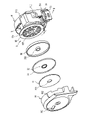
- FIG. 1 shows an example of a measuring device.
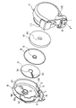
- FIG. 2 is an exploded perspective view (No. 2) showing an example of a measuring device.
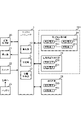
- It is a block diagram which shows an example of the electric structure of a measuring device.
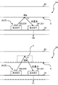
- It is a figure which shows the reading operation of the code pattern by a light emitting element and a light receiving element.
- It is a figure which shows the example of the value read from the code pattern, and the example of the detection operation by a detection circuit.
- It is a flowchart which shows an example of the operation of a microcomputer. It is a flowchart which shows an example of the determination processing of a reel rotation.
- FIGS. 1 and 2 are exploded perspective views showing an example of a measuring device.
- the measuring device has a pair of cases 90, 91, a measure 5, a reel 6, a cover 80, packings 81, 82, a main board 70, and sub boards 71, 72.
- Cases 90 and 91 are examples of the first and second cases, respectively, have a substantially cylindrical shape, and are formed of resin or the like.
- the cases 90 and 91 are removable from each other.
- a major 5 and a reel 6 are housed in the case 91, and a main board 70 and sub-boards 71 and 72 are housed in the case 90.
- the reel 6 is formed of resin or the like as an example, and has a cylindrical shape, for example.
- the reel 6 is rotatably attached to the cases 90 and 91 so as to interlock with the drawer of the measure 5 along the direction D.
- a flange-shaped flange 60 is provided on the side surface of the reel 6 facing the case 90.
- a major 5 is wound around the reel 6.
- the reel 6 is urged by an elastic body such as a spring so as to wind up the measure 5.
- the measure 5 is formed of metal, for example, and is used to measure the length of an object to be measured.
- a scale is printed on one side of the measure 5.
- the tip 50 of the measure 5 is exposed from the opening 911 of the case 91.
- the tip 50 is provided with a hook 51 that is locked around the opening 911 in order to prevent the tip 50 from being wound around the reel 6 and being drawn into the case 91.
- a lock lever 910 for stopping or releasing the winding of the measure 5 is provided above the opening 911 of the case 91.
- the lock lever 910 is attached so as to be slidable on the recesses 912 and 902 of the cases 90 and 91.
- the lock lever 910 is in the unlocked state shown in the figure, the measure 5 is wound around the reel 6 by the urging force of the elastic body.
- the lock lever 910 When the lock lever 910 is slid in the direction L, it is locked and the winding of the measure 5 is suppressed.
- the user can stop the winding of the measure 5 by locking the lock lever 910 while the measure 5 is applied to the object to be measured.
- the flange 60 has a disk shape, and a circular convex shaft 600 is provided at the center of the surface S facing the case 90.
- the shaft 600 is inserted into a circular concave bearing 900 provided at the center of the bottom surface B of the facing case 90. Therefore, the reel 6 can rotate in the direction R about the axis 600 while the measure 5 is pulled out from the opening 911 in the direction D.
- a cord pattern 60a is provided around the axis 600 of the surface S.
- the code pattern 60a is, for example, a Gray code pattern and changes along the rotation direction R of the reel 6. Using the code pattern 60a, the rotation speed and rotation angle of the reel 6 can be obtained.
- the cord pattern 60a is formed by holes provided in the surface S.
- a circular main substrate 70 is provided on the bottom surface B of the case 90.
- the main board 70 is a circuit board on which electronic components are mounted.
- One surface of the main board 70 faces the bottom surface B.
- the other surface of the main board 70 faces the surface S of the flange 60, and a reading sensor 701 for reading the code pattern 60a is mounted on the surface.
- the reading sensor 701 has a plurality of sets of light emitting elements and light receiving elements arranged in a row. The measured value of the measure 5 is calculated from the value of the code pattern 60a read by the reading sensor 701 and transmitted to another device.
- the main board 70 At the center of the main board 70, a through hole 700 fitted to the outer peripheral wall 900a of the bearing 900 is provided. As a result, the main board 70 is fixed in a predetermined position with respect to the case 90.
- the main board 70 is provided with a microcomputer, a communication processing unit, and a display unit, as will be described later.
- a window 903 is provided on the bottom surface B at a position corresponding to the display portion on the main board 70.
- the window 903 is formed of, for example, a transparent resin. The user confirms the display content of the display unit through the window 903.
- the sub-boards 71 and 72 are circuit boards on which electric components are mounted, and are electrically connected to the main board 70 via an electric cable (not shown).
- the main board 70 and the sub boards 71 and 72 are configured as separate boards, but may be configured as one board.
- the sub-board 71 is provided in the case 90 at a position corresponding to the vicinity of the opening 911 of the case 91.
- the sub-board 71 is provided with a detection circuit 26 for detecting the withdrawal of the measure 5.
- the detection circuit 26 has a set of a light emitting element and a light receiving element as described later.
- the sub-board 72 is provided with a switch 22 for starting the measurement by the measure 5.
- the sub-board 72 is provided on the side of the main board 70 so that the switch 22 is exposed from the semi-circular notch 904 provided on the outer peripheral wall of the case 90.
- the cover 80 is fixed to the case 90 with screws or the like.
- the cover 80 covers the reading sensor 701 with a distance between the reel 6 and the reading sensor 701.
- the cover 80 has a circular dish shape, and has an annular insertion portion 800 through which the shaft 600 is inserted at the center thereof.
- the cover 80 protects the reading sensor 701 from dirt such as mud adhering to the measure 5. Since the cover 80 is made of, for example, a transparent resin, it does not interfere with the reading of the code pattern 60a by the reading sensor 701.
- the packings 81 and 82 are formed of an elastic member such as rubber and are used to improve the sealing performance of the measuring device.
- the packing 81 has an annular shape corresponding to the outer peripheral surface of the cover 80
- the packing 82 has an annular shape corresponding to the insertion portion 800 of the cover 80.
- the measuring device can be used again without discarding the expensive main board 70.
- FIG. 3 is a configuration diagram showing an example of the electrical configuration of the measuring device.
- the measuring device includes a microcomputer 1, a communication processing unit 20, a display unit 21, a switch 22, a battery 23, a reading sensor 701, and a detection circuit 26.
- the microcomputer 1, the communication processing unit 20, the display unit 21, the battery 23, and the reading sensor 701 are mounted on the main board 70.
- the switch 22 is mounted on the sub-board 72
- the detection circuit 26 is mounted on the sub-board 71.
- the microcomputer 1 is a circuit including a processor such as a CPU (Central Processing Unit) (not shown) and a memory for storing a program for driving the processor.
- a processor such as a CPU (Central Processing Unit) (not shown)
- a memory for storing a program for driving the processor.
- the microcomputer 1 executes the program, it forms a calculation unit 10, a determination unit 11, and a power supply control unit (hereinafter referred to as “control unit”) 12 as software functions.
- the calculation unit 10, the determination unit 11, and the control unit 12 may be a circuit composed of hardware such as an FPGA (Field Programmable Gate Array) or an ASIC (Application Specified Integrated Circuit).
- the calculation unit 10 calculates the measured value of the measure 5 from the code pattern 60a read by the reading sensor 701.
- the determination unit 11 determines the normality of rotation of the reel 6 based on the detection result of the detection circuit 26 and the change of the code pattern 60a read by the reading sensor 701.
- the control unit 12 controls the power supply to the reading sensor 701 and the detection circuit 26.
- the communication processing unit 20 communicates with other devices such as a smartphone and a personal computer by means such as a wireless LAN (Local Area Network).
- the communication processing unit 20 includes a circuit for performing baseband processing and the like, an antenna, and the like.
- the communication processing unit 20 is an example of a transmission unit, and transmits the measured value of the measure 5 calculated by the calculation unit 10 to another device. Therefore, the measured value of the measure 5 transmitted from the measuring device can be stored in another device.
- the communication processing unit 20 is not limited to wireless communication, and may perform wireless communication.
- the display unit 21 is, for example, a liquid crystal display and displays various information.
- the display surface of the display unit 21 is arranged so as to be visible from the window 903.
- the display unit 21 displays, for example, the occurrence of an abnormality when the determination unit 11 determines that there is an abnormality.
- the measured value calculated by the calculation unit 10 may be displayed on the display unit 21.
- the switch 22 is pressed when the measurement of the measure 5 is executed.
- the microcomputer 1 detects that the switch 22 is pressed, the microcomputer 1 executes a measurement process.
- the battery 23 is, for example, a coin-type battery, and supplies electric power to an electric component such as a microcomputer 1.
- the reading sensor 701 is an example of a reading unit, and optically reads the code pattern 60a provided on the flange 60.
- the reading sensor 701 has a reading unit 24 that reads the angle of the reel 6 from the code pattern 60a, and a reading unit 25 that reads the rotation speed of the reel 6 from the code pattern 60a.
- the reading unit 24 includes a plurality of sets of light emitting elements 240 and light receiving elements 241 arranged in a straight line.
- the reading unit 25 includes a set of light emitting elements 250 and a light receiving element 251.
- the detection circuit 26 includes a set of light emitting elements 260 and a light receiving element 261.
- the light emitting elements 240, 250, 260 are, for example, LEDs (Light Emitting Diodes), and the light receiving elements 241, 51,261 are, for example, phototransistors, but the present invention is not limited thereto.
- FIG. 4 is a diagram schematically showing a reading operation of the code pattern 60a by the light emitting elements 240 and 250 and the light receiving elements 241,251.
- FIG. 4 shows the flange 60 and the main substrate 70 viewed from the side. The cover 80 is not shown.
- the light emitting elements 240 and 250 and the light receiving elements 241,251 of the reading unit 24 and the reading unit 25 are mounted on the main board 70.
- the light emitting elements 240 and 250 irradiate the surface S of the flange 60 with light Ls.
- the light Ls is reflected by the surface S to become the reflected light Lr.
- the reflected light Lr is incident on the light receiving elements 241,251.
- Ga shows an example of a code pattern 60a reading operation at a position without a hole h
- Gb shows an example of a code pattern 60a reading operation at a position with a hole h.
- the light receiving elements 241,251 output a current having an intensity corresponding to the amount of the incident reflected light Lr.
- the light amount of the reflected light Lr from the position without the hole h is larger than the light amount of the reflected light Lr from the position with the hole h (see "high light amount” and "low light amount”). This is because when the hole h is present, the light Ls and the reflected light Lr are attenuated according to the depth of the hole h.
- the current value output by the light receiving elements 241,251 according to the amount of reflected light Lr is also smaller when there is a hole h than when there is no hole h. Therefore, the voltage value VL converted from the current value of the light receiving element 241,251 when the hole h is present is smaller than the voltage value VH when the hole h is not present.
- the voltage value VL when there is a hole h is about 1/20 of the voltage value VH when there is no hole h.
- the microcomputer 1 identifies, for example, the value of the code pattern 60a read at the position without the hole h as the binary number "1", and the value of the code pattern 60a read at the position with the hole h is the binary number. It can be identified as "0".
- the method for identifying the value of the code pattern 60a is not limited to this.
- the code pattern 60a may show different values depending on, for example, the difference in color painted on the surface S.
- the code pattern 60a may indicate a binary number "0" in black and a binary number "1" in white.
- the voltage value of the light receiving elements 241,251 in the black case is about one-third of that in the white case.
- the microcomputer 1 can identify the value of the code pattern 60a.
- the light emitting elements 240 and 250 and the light receiving elements 241,251 use visible light, but the present invention is not limited to this, and the same reading as described above can be performed by using infrared rays, visible rays, ultraviolet rays, and the like.
- Gc in FIG. 5 shows an example of the value read from the code pattern 60a.
- the code pattern 60a includes a lane 611 used for determining the rotation speed and five lanes 610 used for determining the rotation angle.
- the lane 611 is an example of a region showing the rotation speed of the reel 6, and the lane 610 is an example of a region showing the rotation angle of the reel 6.
- the lane 611 is provided with a total of two holes h having a length of one-fourth of the circumference at intervals of 90 degrees around the axis 600.
- the light emitting element 250 and the light receiving element 251 are arranged at positions facing the lane 611, and the light receiving element 251 receives the reflected light from the flange 60 at a position without a hole h in the lane 611.
- the portion of the lane 611 with the hole h corresponds to the binary number "0", and the portion of the lane 611 without the hole h corresponds to the binary number "1".
- the calculation unit 10 and the determination unit 11 detect the rotation speed of the reel 6 by identifying and counting the value of the lane 611 from the voltage value output from the light receiving element 251.
- the value of the lane 611 changes every 90 degrees.
- the calculation unit 10 and the determination unit 11 recognize that the reel 6 has rotated once when the value of the lane 611 changes to the binary numbers "0", “1", “0”, and “1", and “0",
- the rotation speed of the reel 6 is determined based on the number of times the pattern of "1", "0", and "1" is detected.
- the five lanes 610 indicate, for example, a five-digit binary value according to the Gray code.
- Each lane 610 is provided with a hole h at a position indicating a binary number "0", and there is no hole h at a position indicating a binary number "1".
- the light emitting element 240 and the light receiving element 241 are respectively provided at positions facing each lane 610, and the light receiving element 241 receives the reflected light from the flange 60 at a position without a hole h in the lane 610.
- the light emitting element 240 and the light receiving element 241 are provided for each binary digit.
- the calculation unit 10 identifies the value of each lane 610 from the voltage value output from the light receiving element 241 corresponding to each digit, and detects the rotation angle of the reel 6.
- the rotation angle indicates, for example, the amount of displacement of the reel 6 in the rotation direction R with respect to the position of the reel 6 when the measure 5 is completely housed in the cases 90 and 91.
- the calculation unit 10 converts the read lane 610 value into a rotation angle according to a predetermined calculation formula.
- a table or the like may be used to calculate the rotation angle.
- the calculation unit 10 calculates the measured value of the measure 5 from the obtained rotation speed and rotation angle.
- the measured value can be calculated using a calculation formula, a table, or the like.
- the light emitting elements 240 and 250 and the light receiving elements 241,251 optically read the code pattern 60a provided on the side surface of the reel 6 that rotates according to the drawer of the measure 5.
- the code pattern 60a changes along the rotation direction R of the reel 6.
- the calculation unit 10 calculates the measured value of the measure 5 from the values read by the light emitting elements 240 and 250 and the light receiving elements 241,251.
- the calculation unit 10 can calculate the measured value of the measure 5 with high accuracy. Therefore, the measurement accuracy of the measuring device can be improved.
- the light emitting elements 240 and 250 and the light receiving elements 241,251 read the code pattern 60a according to the presence or absence of the hole h on the side surface of the reel. Therefore, for example, as compared with the case where the code pattern 60a is read according to the coating color on the side surface of the reel 6, the code pattern 60a can be read accurately even if dirt adheres to the hole h.
- the code pattern 60a has a lane 611 indicating the rotation speed of the reel 6 and a plurality of lanes 610 indicating the rotation angle of the reel 6.
- the calculation unit 10 calculates the measured value of the measure 5 from the rotation angle and the rotation speed of the reel 6. Therefore, the calculation unit 10 can calculate the measured value with higher accuracy than the case where the measured value is calculated only from the rotation angle.
- FIG. 5 shows an example of the detection operation by the detection circuit 26.
- FIG. 5 shows a scale 5a printed on the surface of the measure 5 and a detection circuit 26 on the sub-board 71.
- the detection circuit 26 includes a light emitting element 260 and a light receiving element 261 facing the surface of the measure 5, and detects the withdrawal of the measure 5.
- the light emitting element 260 irradiates the surface of the measure 5 with light Ls'.
- the light Ls' is reflected on the surface of the measure 5 to become the reflected light Lr'.
- the reflected light Lr' is incident on the light receiving element 261.
- the position of the light Ls'on the surface of the measure 5 is alternately switched between the scale 5a and the portion other than the scale 5a.
- the position where the light Ls'of the light emitting element 260 hits is constant.
- the scale 5a of the major 5 is black, and the parts other than the scale 5a of the major 5 are white. Since the light Ls'of the light emitting element 260 is absorbed when it hits the black scale 5a, the amount of light of the reflected light Lr' incident on the light receiving element 261 is such that the light Ls' is the scale when the light Ls' hits the scale 5a. It is less than when it hits a part other than 5a.
- the amount of reflected light Lr'incident on the light receiving element 261 is substantially constant when the measure 5 is stopped without being pulled out, but changes so as to repeatedly increase and decrease when the measure 5 is pulled out. .. Therefore, the current value output from the light receiving element 261 is also substantially constant when the major 5 is stopped without being pulled out, but changes so as to repeatedly increase and decrease when the major 5 is pulled out.
- the voltage value obtained from the current value is similar to this.
- the calculation unit 10 and the determination unit 11 can determine whether or not the measure 5 is being pulled out according to the change in the voltage value of the light receiving element 261.
- the light emitting element 260 and the light receiving element 261 use visible light, but the present invention is not limited to this, and the same detection as described above can be performed by using infrared rays, visible rays, ultraviolet rays, and the like.
- the determination unit 11 considers an abnormality when the rotation speed of the reel 6 does not change even though the measure 5 is being pulled out, or when the rotation speed of the reel 6 changes even though the measure 5 is stopped. judge. Further, the determination unit 11 rotates the reel 6 when the rotation speed of the reel 6 changes when the measure 5 is being pulled out, or when the rotation speed of the reel 6 does not change when the measure 5 is stopped. Is judged to be normal.
- the detection circuit 26 detects the withdrawal of the measure 5 from the cases 90 and 91.
- the determination unit 11 determines the normality of rotation of the reel 6 based on the detection result of the detection circuit 26 and the change in the value of the code pattern 60a read by the reading sensor 701.
- the measuring device can detect a failure of the reel 6 due to deterioration over time, for example. Since the display unit 21 displays an abnormality in the rotation of the reel 6 as an alarm, the user can receive the alarm and, for example, repair the reel 6 or replace the reel 6 with a new reel 6.
- FIG. 6 is a flowchart showing an example of the operation of the microcomputer 1.
- the control unit 12 activates the reading unit 25 and the detection circuit 26 (St1).
- the control unit 12 controls and activates the power supply to the reading unit 25 and the detection circuit 26 by turning on and off the electric switches, for example, but the control unit 12 is not limited to this.
- step St2 determines whether or not the measure 5 is being pulled out by the detection circuit 26 (St2). If the measure 5 is not being withdrawn (St2 No), the process of step St2 is executed again.
- the calculation unit 10 determines whether or not the rotation of the reel 6 is abnormal based on the determination result of the determination unit 11 (St3).
- the calculation unit 10 determines that the rotation of the reel 6 is abnormal (St3 Yes)
- the calculation unit 10 causes the display unit 21 to display an alarm (St13). As a result, the user is notified of the abnormality of the reel 6.
- the calculation unit 10 determines whether or not the switch 22 is pressed (St4). If the switch 22 is not pressed (St4 No), the process of step St3 is executed again. Further, when the switch 22 is pressed (St4 Yes), the control unit 12 activates the reading unit 24 (St5).
- the control unit 12 controls and activates the power supply by turning on / off the electric switch of the reading unit 24, for example, but the control unit 12 is not limited to this.
- the calculation unit 10 acquires the rotation speed and angle of the reel 6 from the reading result from the reading sensor 701 (St6). At this time, the calculation unit 10 converts the current values output from the light emitting elements 240 and 250 and the light receiving elements 241,251 into voltage values, and acquires the rotation speed and angle of the reel 6.
- the calculation unit 10 calculates the measured value of the measure 5 from the rotation speed and the angle of the reel 6 (St7). Since the rotation speed and angle of the reel 6 are determined according to the drawn length of the measure 5, the measured value of the measure 5 is calculated from the rotation speed and angle of the reel 6 from a predetermined calculation formula.
- the communication processing unit 20 transmits the measured value of the measure 5 to another device (St8).
- the control unit 12 starts the timer (St9).
- the control unit 12 determines whether or not the measure 5 is being pulled out from the detection result of the detection circuit 26 (St10). When the measure 5 is being withdrawn (St10 Yes), each process after step St3 is executed again.
- control unit 12 determines whether or not the timer has expired (St11). If the timer has not expired (St11 No), the St10 process is executed again.
- the control unit 12 stops the power supply to the reading unit 24 so that the operation is stopped (St12).
- the control unit 12 starts the reading unit 24 only when the switch 22 is pressed and the measurement is performed by the measure 5, and stops the power supply to the reading unit 24 when the timer expiration time elapses after the measurement. do. That is, the reading unit 24 is supplied with power only at the time of measurement. Therefore, the power consumption of the reading unit 24 is reduced as compared with the case where power is constantly supplied. After that, the process of step St2 is executed again.
- FIG. 7 is a flowchart showing an example of the reel rotation determination process.
- the determination unit 11 determines whether or not the rotation speed of the reel 6 has changed based on the value of the lane 611 in the code pattern 60a read by the reading unit 25 (St21).
- the determination unit 11 determines whether or not the measure 5 is being pulled out based on the detection result of the detection circuit 26 (St22). If it is determined that the major 5 is not being pulled out (St22 No), there is a possibility that the reel 6 is spinning even though the major 5 is stopped, so the determination unit 11 Determines that the rotation of the reel 6 is abnormal (St24).
- the determination unit 11 determines that the rotation of the reel 6 is normal (St23).
- the determination unit 11 determines that the rotation of the reel 6 is abnormal when the rotation of the reel 6 and the withdrawal of the measure 5 do not interlock with each other. Therefore, it is possible to detect a failure of the reel 6.
Landscapes
- Physics & Mathematics (AREA)
- General Physics & Mathematics (AREA)
- Length Measuring Devices By Optical Means (AREA)
- Optical Transform (AREA)
Abstract
測定装置は、メジャーと、前記メジャーが巻き回され、前記メジャーの引き出しに従って回転し、回転方向に沿って変化するコードパタンが設けられたリールと、前記コードパタンを光学的に読み取る読み取り部と、前記読み取り部による読み取り結果から前記メジャーの測定値を算出する算出部とを有する。
Description
本発明は、測定装置に関する。
メジャーを備える測定装置に関し、特許文献1には、メジャーのメモリの画像を認識することにより長さを測定する点が記載されている。
しかし、メジャーは測定装置の本体から引き出されて測定対象物にあてがわれるため、汚れが付着しやすく、測定値に誤差が生ずるおそれがある。例えばコンベックスのように屋外で多く使用されるメジャーは、泥や油などの汚れが付着しやすい。
本発明は、測定精度を向上することができる測定装置を提供することを目的とする。
1つの態様では、測定装置は、メジャーと、前記メジャーが巻き回され、前記メジャーの引き出しに従って回転し、回転方向に沿って変化するコードパタンが設けられたリールと、前記コードパタンを光学的に読み取る読み取り部と、前記読み取り部による読み取り結果から前記メジャーの測定値を算出する算出部とを有する。
本発明によると、測定精度を向上することができる。
図1及び図2は、測定装置の一例を示す分解斜視図である。測定装置は、一対のケース90,91、メジャー5、リール6、カバー80、パッキン81,82、及びメイン基板70、サブ基板71,72を有する。
ケース90,91は、それぞれ第1及び第2ケースの一例であり、略円筒形状を有し、樹脂などにより形成されている。ケース90,91は、互いに着脱自在である。ケース91にはメジャー5及びリール6が収容され、ケース90にはメイン基板70及びサブ基板71,72が収容される。
リール6は、一例として樹脂などにより形成され、例えば円筒形状を有している。リール6は、方向Dに沿ったメジャー5の引き出しと連動するように、ケース90,91に対して回転自在に取り付けられている。ケース90に対向するリール6の側面には、鍔状のフランジ60が設けられている。リール6にはメジャー5が巻き回されている。リール6は、メジャー5を巻き取るようにバネ等の弾性体により付勢されている。
メジャー5は、例えば金属により形成され、測定対象物の長さを測定するために用いられる。メジャー5の一方の面には目盛りが印刷されている。メジャー5の先端50はケース91の開口911から露出している。先端50には、先端50がリール6に巻き取られてケース91内に引き込まれるのを防止するため、開口911の周辺に係止されるフック51が設けられている。
ケース91の開口911の上部には、メジャー5の巻き取りを停止または停止解除するロックレバー910が設けられている。ロックレバー910は、ケース90,91の凹部912,902上をスライドできるように取り付けられている。ロックレバー910が図示されたアンロック状態である場合、メジャー5は弾性体の付勢力によりリール6に巻き取られる。
ロックレバー910は、方向Lにスライドされるとロック状態となり、メジャー5の巻き取りが抑制される。ユーザは、測定対象物にメジャー5を当てている間、ロックレバー910をロック状態とすることにより、メジャー5の巻き取りを停止させることができる。
フランジ60は円盤形状を有し、ケース90と対向する面Sの中心には、円形の凸部形状の軸600が設けられている。軸600は、対向するケース90の底面Bの中心に設けられた円形の凹状の軸受け900に挿入される。このため、リール6は、メジャー5が開口911から方向Dに引き出されている間、軸600を中心として方向Rに回転することができる。
面Sの軸600の周囲には、コードパタン60aが設けられている。コードパタン60aは、例えばグレイコードのパタンであり、リール6の回転方向Rに沿って変化する。コードパタン60aを用いて、リール6の回転数及び回転角度が求められる。一例として、コードパタン60aは面Sに設けられた穴により形成される。
ケース90の底面Bには、円形状のメイン基板70が設けられている。メイン基板70は、電子部品が実装された回路基板である。メイン基板70の一方の面は底面Bに対向する。また、メイン基板70の他方の面はフランジ60の面Sに対向し、その面上にはコードパタン60aを読み取る読取センサ701が実装されている。読取センサ701は、後述するように、一列に並んだ複数組の発光素子及び受光素子を有する。メジャー5の測定値は、読取センサ701が読み取ったコードパタン60aの値から算出されて他装置に送信される。
メイン基板70の中心には、軸受け900の外周壁900aに嵌合される貫通孔700が設けられている。これにより、メイン基板70は、ケース90に対して所定位置に固定される。なお、メイン基板70には、後述するように、マイクロコンピュータ、通信処理部、及び表示部が設けられている。
底面Bには、メイン基板70上の表示部に対応する位置に窓903が設けられている。窓903は、例えば透明な樹脂などにより形成されている。ユーザは、窓903を介して表示部の表示内容を確認する。
サブ基板71,72は、電気部品が実装された回路基板であり、不図示の電気ケーブルを介してメイン基板70と電気的に接続されている。メイン基板70及びサブ基板71,72は、別々の基板として構成されているが、1つの基板として構成されてもよい。
サブ基板71は、ケース90内において、ケース91の開口911の近傍に対応する位置に設けられている。サブ基板71には、メジャー5の引き出しを検知する検知回路26が設けられている。検知回路26は、後述するように一組の発光素子及び受光素子を有する。
サブ基板72には、メジャー5による測定を開始するためのスイッチ22が設けられている。サブ基板72は、ケース90の外周壁に設けられた半円状の切り欠き904からスイッチ22が露出するように、メイン基板70の側方に設けられている。
カバー80は、ネジなどによりケース90に固定される。カバー80は、リール6と読取センサ701の間を隔て、読取センサ701を覆う。カバー80は円形の皿形状を有し、その中心には軸600が挿通される環状の挿通部800を有する。カバー80は、読取センサ701を、メジャー5に付着した泥などの汚れから読取センサ701を保護する。カバー80は例えば透明な樹脂などから形成されるため、読取センサ701によるコードパタン60aの読み取りの支障にならない。
パッキン81,82は、例えばゴムなどの弾性部材により形成され、測定装置の封止性の向上に用いられる。パッキン81はカバー80の外周面に応じた円環形状を有し、パッキン82はカバー80の挿通部800に応じた円環形状を有する。パッキン81をカバー80とケース90の間に挟み込むことにより、ケース90内のメイン基板70を外部に対して封止する。また、パッキン82をカバー80とメイン基板70の間に挟み込むことにより、ケース90内のメイン基板70を外部に対して封止する。このため、例えば開口911から侵入した水や埃などがメイン基板70に付着することが防止できる。
仮にケース90,91内に水や埃などの異物が侵入したとしても、ケース90,91は互いに着脱自在であるため、異物の除去が容易である。さらに、ケース90にはメイン基板70が収容され、ケース91にはリール6が収容されるため、リール6が故障しても、リール6が収容されたケース91だけを新たなケース91と交換してケース90と組み合わせれば、高価なメイン基板70を廃棄することなく、測定装置が再度使用可能となる。
図3は、測定装置の電気的な構成の一例を示す構成図である。測定装置は、マイクロコンピュータ1、通信処理部20、表示部21、スイッチ22、バッテリ23、読取センサ701、及び検知回路26を有する。
例えば、マイクロコンピュータ1、通信処理部20、表示部21、バッテリ23、及び読取センサ701はメイン基板70に実装される。また、例えば、スイッチ22はサブ基板72に実装され、検知回路26はサブ基板71に実装される。
マイクロコンピュータ1は、不図示のCPU(Central Processing Unit)などのプロセッサ、及びプロセッサを駆動するプログラムなどを記憶するメモリを含む回路である。マイクロコンピュータ1は、プログラムを実行すると、ソフトウェアの機能として、算出部10、判定部11、及び給電制御部(以下「制御部」)12を形成する。算出部10、判定部11、及び制御部12は、例えばFPGA(Field Programmable Gate Array)やASIC(Application Specified Integrated Circuit)などのハードウェアから構成される回路であってもよい。
算出部10は、読取センサ701が読み取ったコードパタン60aからメジャー5の測定値を算出する。判定部11は、検知回路26の検知結果、及び読取センサ701が読み取ったコードパタン60aの変化に基づいてリール6の回転の正常性を判定する。制御部12は、読取センサ701及び検知回路26への給電を制御する。
通信処理部20は、例えば無線LAN(Local Area Network)などの手段によりスマートフォンやパーソナルコンピュータなどの他の装置と通信する。通信処理部20は、ベースバンド処理などを行う回路及びアンテナなどを含む。通信処理部20は送信部の一例であり、算出部10が算出したメジャー5の測定値を他の装置に送信する。このため、測定装置から送信したメジャー5の測定値を他の装置に保存することができる。なお、通信処理部20は、無線に限定されず、有線により通信を行ってもよい。
表示部21は、例えば液晶ディスプレイであり、各種の情報を表示する。表示部21の表示面は窓903から見えるように配置されている。表示部21は、例えば判定部11により異常が有ると判定された場合に異常の発生を表示する。表示部21には、算出部10が算出した測定値を表示してもよい。
スイッチ22は、メジャー5の測定の実行時に押下される。マイクロコンピュータ1は、スイッチ22が押下されたことを検出すると、測定の処理を実行する。
バッテリ23は例えばコイン型電池であり、マイクロコンピュータ1などの電気部品に電力を供給する。
読取センサ701は、読み取り部の一例であり、フランジ60に設けられたコードパタン60aを光学的に読み取る。読取センサ701は、コードパタン60aからリール6の角度を読み取る読み取り部24、及びコードパタン60aからリール6の回転数を読み取る読み取り部25を有する。
読み取り部24は、直線状に配列された複数組の発光素子240及び受光素子241を含む。読み取り部25は、一組の発光素子250及び受光素子251を含む。検知回路26は、一組の発光素子260及び受光素子261を含む。発光素子240,250,260は例えばLED(Light Emitting Diode)であり、受光素子241,251,261は例えばフォトトランジスタであるが、これに限定されない。
図4は、発光素子240,250及び受光素子241,251によるコードパタン60aの読み取り動作を模式的に示す図である。図4には、側面視したフランジ60及びメイン基板70が示されている。なお、カバー80の図示は省略する。
メイン基板70には読み取り部24及び読み取り部25の発光素子240,250及び受光素子241,251が実装されている。発光素子240,250はフランジ60の面Sに光Lsを照射する。光Lsは面Sで反射されて反射光Lrとなる。反射光Lrは受光素子241,251に入射する。
Gaは、穴hが無い位置でのコードパタン60aの読み取り動作の一例を示し、Gbは、穴hが有る位置でのコードパタン60aの読み取り動作の一例を示す。受光素子241,251は、入射した反射光Lrの光量に応じた強さの電流を出力する。穴hが無い位置からの反射光Lrの光量は、穴hが有る位置からの反射光Lrの光量より多い(「光量多」及び「光量少」参照)。これは穴hが有る場合、穴hの深さに応じて光Ls及び反射光Lrが減衰するためである。
このため、受光素子241,251が反射光Lrの光量に応じて出力する電流値も、穴hが有る場合の方が穴hの無い場合より小さい。したがって、穴hが有る場合の受光素子241,251の電流値を変換した電圧値VLは、穴hが無い場合の電圧値VHより小さい。例えば穴hが有る場合の電圧値VLは、穴hが無い場合の電圧値VHの20分の1程度である。これにより、マイクロコンピュータ1は例えば、穴hが無い位置で読み取ったコードパタン60aの値を2進数の「1」と識別し、穴hが有る位置で読み取ったコードパタン60aの値を2進数の「0」と識別することができる。
コードパタン60aの値の識別手法は、これに限定されない。コードパタン60aは、例えば面Sに塗装された色の違いにより異なる値を示してもよい。例えばコードパタン60aは、黒色により2進数の「0」を示し、白色により2進数の「1」を示してもよい。このとき、黒色の場合の受光素子241,251の電圧値は、白色の場合の3分の1程度である。このような電圧値の違いにより、マイクロコンピュータ1は、コードパタン60aの値を識別することができる。発光素子240,250及び受光素子241,251は可視光を用いているが、これに限定されず、赤外線、可視光線、紫外線などを利用しても上記と同様の読み取りを行うことができる。
図5のGcは、コードパタン60aから読み取った値の一例を示す。コードパタン60aは、回転数を判別するために用いられるレーン611と、回転角度を判別するために用いられる5個のレーン610とを含む。レーン611は、リール6の回転数を示す領域の一例であり、レーン610は、リール6の回転角度を示す領域の一例である。
レーン611には、軸600を中心として90度おきに、一周の4分の1の長さの穴hが計2つ設けられている。発光素子250及び受光素子251は、レーン611に対向する位置に配置されており、受光素子251はレーン611の穴hのない位置でフランジ60からの反射光を受光する。穴hのあるレーン611の部分は2進数の「0」に対応し、穴hのないレーン611の部分は2進数の「1」に対応する。算出部10及び判定部11は、受光素子251から出力される電圧値からレーン611の値を識別して計数することによりリール6の回転数を検出する。
リール6が回転方向Rに回転すると、レーン611の値が90度回転するごとに変化する。算出部10及び判定部11は、レーン611の値が2進数の「0」,「1」,「0」,「1」と変化したときリール6が1回転したと認識し、「0」、「1」、「0」、「1」のパタンの検出回数に基づいてリール6の回転数を判別する。
5個のレーン610は、例えばグレイコードに従った5桁の2進数の値を示す。各レーン610には、2進数の「0」を示す位置に穴hが設けられ、2進数の「1」を示す位置には穴hが無い。発光素子240及び受光素子241は、各レーン610に対向する位置にそれぞれ設けられており、受光素子241はレーン610の穴hのない位置でフランジ60からの反射光を受光する。発光素子240及び受光素子241は、2進数の桁ごとに設けられている。
算出部10は、各桁に対応する受光素子241から出力される電圧値から各レーン610の値を識別して、リール6の回転角度を検出する。回転角度は、例えばメジャー5が完全にケース90,91内に収容されたときのリール6の位置を基準とする回転方向Rへのリール6の変位量を示す。
リール6が回転方向Rに回転すると、各桁に対応する発光素子240及び受光素子241に対向するレーン610の位置が変化する。各桁の発光素子240及び受光素子241が位置610aに対向する場合は2進数の「00111」が読み出され、各桁の発光素子240及び受光素子241が位置610bに対向する場合は2進数の「00101」が読み出される。各桁の発光素子240及び受光素子241が位置610cに対向する場合、2進数の「00100」が読み出される。
算出部10は、読み出されたレーン610の値を所定の算出式に従って回転角度に変換する。回転角度の算出にはテーブルなどを用いてもよい。
メジャー5の引き出し量とリール6の回転数及び回転角度には相関関係があるので、算出部10は求められた回転数及び回転角度からメジャー5の測定値を算出する。測定値は、算出式、テーブルなどを用いて算出することができる。
このように、発光素子240,250及び受光素子241,251は、メジャー5の引き出しに従って回転するリール6の側面に設けられたコードパタン60aを光学的に読み取る。コードパタン60aはリール6の回転方向Rに沿って変化する。算出部10は、発光素子240,250及び受光素子241,251が読み取った値からメジャー5の測定値を算出する。
上記の構成によると、コードパタン60aはリール6に設けられているため、メジャー5に泥や油などの汚れが付着しても、その汚れはコードパタン60aに付着しにくい。このため、算出部10は、高精度にメジャー5の測定値を算出することができる。したがって、測定装置の測定精度を向上することができる。
発光素子240,250及び受光素子241,251は、コードパタン60aをリールの側面の穴hの有無に応じて読み取る。このため、例えばコードパタン60aをリール6の側面の塗装色に応じて読み取る場合と比べると、穴hに汚れが付着しても精度よくコードパタン60aを読み取ることができる。
コードパタン60aは、リール6の回転数を示すレーン611と、リール6の回転角度を示す複数のレーン610とを有する。算出部10は、リール6の回転角度及び回転数からメジャー5の測定値を算出する。このため、算出部10は、回転角度のみから測定値を算出する場合より高精度に測定値を算出することができる。
図5のGdは、検知回路26による検知動作の一例を示す。図5には、メジャー5の表面に印刷された目盛り5a、及びサブ基板71上の検知回路26が示されている。検知回路26は、メジャー5の表面に対向する発光素子260及び受光素子261を含み、メジャー5の引き出しを検知する。
発光素子260は、メジャー5の表面に光Ls’を照射する。光Ls’はメジャー5の表面で反射されて反射光Lr’となる。反射光Lr’は受光素子261に入射する。
メジャー5が方向Dに引き出されているとき、メジャー5の表面においての光Ls’の当たる位置は、目盛り5aと目盛り5a以外の部分とで交互に切り替わる。一方、メジャー5が引き出されずに停止しているとき、発光素子260の光Ls’の当たる位置は一定である。
例えばメジャー5の目盛り5aは黒色であり、メジャー5の目盛り5a以外の部分は白色である。発光素子260の光Ls’は黒色の目盛り5aに当たると吸収されるため、受光素子261に入射する反射光Lr’の光量は、光Ls’が目盛り5aに当たる場合の方が、光Ls’が目盛り5a以外の部分にあたる場合より減少する。
受光素子261に入射する反射光Lr’の光量は、メジャー5が引き出されずに停止しているときは実質的に一定であるが、メジャー5が引き出されているときは増減を繰り返すように変化する。このため、受光素子261から出力される電流値も、メジャー5が引き出されずに停止しているときは実質的に一定であるが、メジャー5が引き出されているときには増減を繰り返すように変化する。電流値から得られる電圧値も、これと同様である。
よって、算出部10及び判定部11は、受光素子261の電圧値の変化に応じてメジャー5が引き出し中であるか否かを判定することができる。なお、発光素子260及び受光素子261は可視光を用いているが、これに限定されず、赤外線、可視光線、紫外線などを用いて上記と同様の検知を行うことができる。
判定部11は、メジャー5が引き出し中であるにも関わらずリール6の回転数が変化しない場合、またはメジャー5が停止中であるにも関わらずリール6の回転数が変化する場合、異常と判定する。また、判定部11は、メジャー5が引き出し中であるときにリール6の回転数が変化する場合、またはメジャー5が停止中であるときにリール6の回転数が変化しない場合、リール6の回転を正常と判定する。
このように、検知回路26はケース90,91からのメジャー5の引き出しを検知する。判定部11は、検知回路26の検知結果、及び読取センサ701が読み取ったコードパタン60aの値の変化に基づいてリール6の回転の正常性を判定する。
このため、測定装置は、例えば経年劣化によるリール6の故障を検出することができる。表示部21はリール6の回転の異常を警報として表示するため、ユーザは警報を受けて、例えばリール6を修理し、またはリール6を新しいリール6に交換することができる。
次にマイクロコンピュータ1の動作を説明する。
図6は、マイクロコンピュータ1の動作の一例を示すフローチャートである。測定装置の電源がオンになると、制御部12は、読み取り部25及び検知回路26を起動する(St1)。制御部12は、例えば読み取り部25及び検知回路26の電気的なスイッチをオンオフすることによりこれらへの給電を制御して起動するが、これに限定されない。
次に算出部10は、検知回路26によりメジャー5が引き出し中であるか否かを判定する(St2)。メジャー5が引き出し中ではない場合(St2 No)、再びステップSt2の処理が実行される。
また、メジャー5が引き出し中である場合(St2 Yes)、算出部10は、判定部11の判定結果に基づいてリール6の回転が異常であるか否かを判定する(St3)。算出部10は、リール6の回転が異常であると判定した場合(St3 Yes)、表示部21に警報を表示させる(St13)。これにより、ユーザにリール6の異常が通知される。
また、算出部10は、リール6の回転が正常である場合(St3 No)、スイッチ22が押下されたか否かを判定する(St4)。スイッチ22が押下されていない場合(St4 No)、再びステップSt3の処理が実行される。また、スイッチ22が押下された場合(St4 Yes)、制御部12は読み取り部24を起動する(St5)。制御部12は、例えば読み取り部24の電気的なスイッチをオンオフすることにより給電を制御して起動するが、これに限定されない。
次に算出部10は、読取センサ701からの読取結果からリール6の回転数及び角度を取得する(St6)。このとき、算出部10は、発光素子240,250及び受光素子241,251から出力される電流値を電圧値に変換して、リール6の回転数及び角度を取得する。
次に算出部10は、リール6の回転数及び角度からメジャー5の測定値を算出する(St7)。リール6の回転数及び角度は、メジャー5の引き出された長さに応じて決定されるため、メジャー5の測定値は、リール6の回転数及び角度から所定の算出式から算出される。
次に通信処理部20は、メジャー5の測定値を他の装置に送信する(St8)。次に制御部12は、タイマをスタートさせる(St9)。次に制御部12は、検知回路26の検知結果からメジャー5が引き出し中であるか否かを判定する(St10)。メジャー5が引き出し中である場合(St10 Yes)、再びステップSt3以降の各処理が実行される。
また、メジャー5が引き出し中ではない場合(St10 No)、制御部12は、タイマが満了したか否かを判定する(St11)。タイマが満了していない場合(St11 No)、再びSt10の処理が実行される。
また、制御部12は、タイマが満了した場合(St11 Yes)、動作が停止するように読み取り部24への給電を停止する(St12)。このように、制御部12は、スイッチ22が押下されてメジャー5により測定を行う場合だけ読み取り部24を起動し、測定後、タイマの満了時間が経過した場合に読み取り部24への給電を停止する。つまり、読み取り部24は測定時のみ給電される。このため、読み取り部24の消費電力は、常時給電する場合より低減される。その後、再びステップSt2の処理が実行される。
次に、St3におけるリール6の回転の正常性の判定処理を説明する。
図7は、リール回転の判定処理の一例を示すフローチャートである。判定部11は、読み取り部25が読み取ったコードパタン60aにレーン611の値に基づいてリール6の回転数が変化しているか否かを判定する(St21)。
判定部11は、リール6の回転数が変化している場合(St21 Yes)、検知回路26の検知結果に基づいて、メジャー5が引き出し中であるか否かを判定する(St22)。メジャー5が引き出し中ではないと判定した場合(St22 No)、メジャー5が停止中であるにも関わらずリール6が空回りしているなどの状況となっている可能性があるため、判定部11はリール6の回転が異常であると判定する(St24)。
また、メジャー5が引き出し中である場合(St22 Yes)、判定部11は、リール6の回転が正常であると判定する(St23)。
また、リール6の回転数が変化しない場合(St21 No)、検知回路26の検知結果に基づいて、メジャー5が引き出し中であるか否かを判定する(St24)。メジャー5が引き出し中ではない場合(St24 No)、判定部11は、リール6の回転が正常であると判定する(St25)。
また、メジャー5が引き出し中である場合(St24 Yes)、メジャー5が引き出し中であるにも関わらずリール6が停止しているため、判定部11は、リール6の回転が異常であると判定する(St26)。このようにして、リール6の回転の正常性の判定処理は実行される。
このように、判定部11は、リール6の回転及びメジャー5の引き出しが互いに連動しない場合、リール6の回転が異常であると判定する。このため、リール6の故障の検出が可能である。
上述した実施形態は本発明の好適な実施の例である。但し、これに限定されるものではなく、本発明の要旨を逸脱しない範囲内において種々変形実施可能である。
1 マイクロコンピュータ
5 メジャー
6 リール
10 算出部
11 判定部
20 通信処理部
26 検知回路
60a コードパタン
80 カバー
90,91 ケース
610,611 レーン
701 読取センサ
5 メジャー
6 リール
10 算出部
11 判定部
20 通信処理部
26 検知回路
60a コードパタン
80 カバー
90,91 ケース
610,611 レーン
701 読取センサ
Claims (6)
- メジャーと、
前記メジャーが巻き回され、前記メジャーの引き出しに従って回転し、回転方向に沿って変化するコードパタンが設けられたリールと、
前記コードパタンを光学的に読み取る読み取り部と、
前記読み取り部による読み取り結果から前記メジャーの測定値を算出する算出部とを有する、
測定装置。 - 前記読み取り部は、前記コードパタンを前記リールの側面の穴の有無に応じて読み取る、
請求項1に記載の測定装置。 - 前記コードパタンは、前記リールの回転角度を示す領域と、前記リールの回転数を示す領域とを有し、
前記算出部は、前記リールの回転角度及び回転数から前記測定値を算出することを特徴とする、
請求項1または2に記載の測定装置。 - 前記測定装置からの前記メジャーの引き出しを検知する検知部と、
前記検知部の検知結果、及び前記読み取り部が読み取った値の変化に基づいて前記リールの回転の正常性を判定する判定部とを有する、
請求項1乃至3の何れかに記載の測定装置。 - 互いに着脱自在な第1ケース及び第2ケースを有し、
前記第1ケースは、前記メジャーが巻き回された前記リールを収容し、
前記第2ケースは、前記読み取り部及び前記算出部を収容する、
請求項1乃至4の何れかに記載の測定装置。 - 前記測定値を他の装置に送信する送信部を有する、
請求項1乃至5の何れかに記載の測定装置。
Priority Applications (3)
| Application Number | Priority Date | Filing Date | Title |
|---|---|---|---|
| CN202080005396.2A CN114616436A (zh) | 2020-09-30 | 2020-09-30 | 测量装置 |
| US17/281,373 US20220307810A1 (en) | 2020-09-30 | 2020-09-30 | Measuring device |
| PCT/JP2020/037340 WO2022070366A1 (ja) | 2020-09-30 | 2020-09-30 | 測定装置 |
Applications Claiming Priority (1)
| Application Number | Priority Date | Filing Date | Title |
|---|---|---|---|
| PCT/JP2020/037340 WO2022070366A1 (ja) | 2020-09-30 | 2020-09-30 | 測定装置 |
Publications (1)
| Publication Number | Publication Date |
|---|---|
| WO2022070366A1 true WO2022070366A1 (ja) | 2022-04-07 |
Family
ID=80949953
Family Applications (1)
| Application Number | Title | Priority Date | Filing Date |
|---|---|---|---|
| PCT/JP2020/037340 Ceased WO2022070366A1 (ja) | 2020-09-30 | 2020-09-30 | 測定装置 |
Country Status (3)
| Country | Link |
|---|---|
| US (1) | US20220307810A1 (ja) |
| CN (1) | CN114616436A (ja) |
| WO (1) | WO2022070366A1 (ja) |
Families Citing this family (2)
| Publication number | Priority date | Publication date | Assignee | Title |
|---|---|---|---|---|
| US11859968B2 (en) * | 2021-06-07 | 2024-01-02 | Kirk Steven Tecu | Measuring tape with preset length |
| JP1743485S (ja) * | 2022-06-14 | 2023-05-08 | 測量尺 |
Citations (4)
| Publication number | Priority date | Publication date | Assignee | Title |
|---|---|---|---|---|
| JPH05501915A (ja) * | 1989-06-02 | 1993-04-08 | テープルール リミテッド ライアビリティー カンパニー | ディジタル式線形測定装置 |
| JPH11344360A (ja) * | 1998-05-29 | 1999-12-14 | Tokai Rika Co Ltd | 回転位置検出装置及び回転位置検出センサ |
| JP2005291834A (ja) * | 2004-03-31 | 2005-10-20 | Nippon Acp Kk | 電子式メジャー装置 |
| JP2018081044A (ja) * | 2016-11-18 | 2018-05-24 | ネポン株式会社 | 長さ測定装置 |
Family Cites Families (27)
| Publication number | Priority date | Publication date | Assignee | Title |
|---|---|---|---|---|
| US5142793A (en) * | 1989-06-02 | 1992-09-01 | Contek Corporation | Digital linear measuring device |
| US5433014A (en) * | 1994-09-19 | 1995-07-18 | Falk; David C. | Digital tape rule with transmitter |
| US5743021A (en) * | 1996-02-06 | 1998-04-28 | Corcoran; Bradley H. | Digital length gauge |
| US5894678A (en) * | 1997-01-29 | 1999-04-20 | Mitutoyo Corporation | Electronic linear tape measure using a low power induced current position transducer |
| US5983514A (en) * | 1997-04-28 | 1999-11-16 | Measureminder, L.L.C. | Tape measure with manual entry electronic measurement recording feature |
| TWM254585U (en) * | 2004-03-19 | 2005-01-01 | Globlink Technology Inc | Electronic length measurement device |
| CN202470927U (zh) * | 2012-03-06 | 2012-10-03 | 王文波 | 一种土地测绘用卷尺 |
| US9417054B2 (en) * | 2014-05-15 | 2016-08-16 | Textron Innovations Inc. | Digital measurement unit for fish tape device or duct rodding device |
| US9774986B2 (en) * | 2014-08-07 | 2017-09-26 | Charles Hoge | Bluetooth tape measure system |
| CN104764391B (zh) * | 2015-03-13 | 2018-04-27 | 康凯 | 一种电子钢卷尺 |
| CN106556303B (zh) * | 2015-09-30 | 2019-12-03 | 捷荣科技集团有限公司 | 一种可测围的智能卷尺及其测围方法 |
| CN105258587A (zh) * | 2015-11-25 | 2016-01-20 | 重庆段氏服饰实业有限公司 | 一种卷尺 |
| CA2976553A1 (en) * | 2016-10-31 | 2018-04-30 | Bagel Labs Co., Ltd. | Length measuring device |
| CN206160851U (zh) * | 2016-11-14 | 2017-05-10 | 优乐(武汉)健康科技有限公司 | 一种自读数电子卷尺 |
| CN106767221B (zh) * | 2016-12-28 | 2018-10-30 | 广州聚旭机电技术研究院有限公司 | 智能卷尺及其测量方法 |
| CN206670614U (zh) * | 2017-04-06 | 2017-11-24 | 珠海码硕科技有限公司 | 带卷尺功能的测距仪 |
| CN107289832A (zh) * | 2017-06-06 | 2017-10-24 | 辽宁师范大学 | 一种智能钢尺 |
| CN107388914A (zh) * | 2017-08-02 | 2017-11-24 | 王振兴 | 数字卷尺 |
| US10859363B2 (en) * | 2017-09-27 | 2020-12-08 | Stanley Black & Decker, Inc. | Tape rule assembly with linear optical encoder for sensing human-readable graduations of length |
| FR3073389B1 (fr) * | 2017-11-16 | 2023-02-10 | Laboratoires Innothera | Dispositif de mesure d'une mensuration |
| KR102006757B1 (ko) * | 2017-12-29 | 2019-08-02 | (주)인천측기 | 길이 측정 장치 및 시스템 |
| CN209285505U (zh) * | 2018-02-06 | 2019-08-23 | 翰长生物医疗(深圳)有限公司 | 便携式体检仪 |
| JP7118748B2 (ja) * | 2018-06-01 | 2022-08-16 | 富士通コンポーネント株式会社 | 計測器および光学読取器 |
| JP7411325B2 (ja) * | 2018-12-26 | 2024-01-11 | 富士通コンポーネント株式会社 | 計測器 |
| AU2020353716B2 (en) * | 2019-09-26 | 2025-12-18 | Leopard Systems Pty Ltd | Apparatus and system for measuring dimensions of freight items |
| US11980962B2 (en) * | 2020-11-19 | 2024-05-14 | Preston Busby | Energy weld welding calculator and monitoring system and device |
| US11460284B1 (en) * | 2021-06-16 | 2022-10-04 | Reekon Tools, Inc. | Digital linear measuring device |
-
2020
- 2020-09-30 CN CN202080005396.2A patent/CN114616436A/zh active Pending
- 2020-09-30 WO PCT/JP2020/037340 patent/WO2022070366A1/ja not_active Ceased
- 2020-09-30 US US17/281,373 patent/US20220307810A1/en not_active Abandoned
Patent Citations (4)
| Publication number | Priority date | Publication date | Assignee | Title |
|---|---|---|---|---|
| JPH05501915A (ja) * | 1989-06-02 | 1993-04-08 | テープルール リミテッド ライアビリティー カンパニー | ディジタル式線形測定装置 |
| JPH11344360A (ja) * | 1998-05-29 | 1999-12-14 | Tokai Rika Co Ltd | 回転位置検出装置及び回転位置検出センサ |
| JP2005291834A (ja) * | 2004-03-31 | 2005-10-20 | Nippon Acp Kk | 電子式メジャー装置 |
| JP2018081044A (ja) * | 2016-11-18 | 2018-05-24 | ネポン株式会社 | 長さ測定装置 |
Also Published As
| Publication number | Publication date |
|---|---|
| US20220307810A1 (en) | 2022-09-29 |
| CN114616436A (zh) | 2022-06-10 |
Similar Documents
| Publication | Publication Date | Title |
|---|---|---|
| WO2022070366A1 (ja) | 測定装置 | |
| TWI558979B (zh) | 編碼器之輸出訊號監視系統及編碼器之輸出訊號監視方法 | |
| US20070287182A1 (en) | Method and apparatus for analyzing solutions | |
| CN101730849B (zh) | 用于定位的光学传感器 | |
| JP6717313B2 (ja) | 測色計 | |
| US20070075230A1 (en) | Method and system of detecting eccentricity and up/down movement of a code wheel of an optical encoder set | |
| KR20210115860A (ko) | 카메라 모듈의 회전 위치를 센싱하는 포토 센서 어셈블리 | |
| US20260097157A1 (en) | Pump monitored by sensor | |
| JP2021056040A (ja) | 測定装置 | |
| US10467991B2 (en) | Measurement instrument and reflection device used for same | |
| TWI502434B (zh) | 觸控模組及其觸控定位方法 | |
| JP6411906B2 (ja) | 回転計 | |
| JP2019144080A (ja) | エンコーダおよびバックアップ電流異常判定方法 | |
| KR101720793B1 (ko) | 회전각 측정 장치 및 그 동작 방법 | |
| CN109557032B (zh) | 浊度测量装置 | |
| JP5546001B2 (ja) | 回転計 | |
| US20180080804A1 (en) | Illuminated dial with integrated status indication | |
| KR101307644B1 (ko) | 체액 샘플 테스트 시스템 | |
| CN111923659A (zh) | 万向轮的转向检测结构以及移动机器人 | |
| US7911204B2 (en) | Reel shaft of barcode printer | |
| KR100731275B1 (ko) | 비반사면을 가지는 반사부를 이용한 구조물 진동레벨감지장치 | |
| JP2011094993A (ja) | 回転計 | |
| TWM581195U (zh) | Head monitoring device | |
| KR200409894Y1 (ko) | 회전체의 회전속도 검출장치 | |
| JP7821472B2 (ja) | 検出器 |
Legal Events
| Date | Code | Title | Description |
|---|---|---|---|
| 121 | Ep: the epo has been informed by wipo that ep was designated in this application |
Ref document number: 20956294 Country of ref document: EP Kind code of ref document: A1 |
|
| NENP | Non-entry into the national phase |
Ref country code: DE |
|
| 122 | Ep: pct application non-entry in european phase |
Ref document number: 20956294 Country of ref document: EP Kind code of ref document: A1 |
|
| NENP | Non-entry into the national phase |
Ref country code: JP |