WO2022070301A1 - 生体判定システム、生体判定方法、及びコンピュータプログラム - Google Patents
生体判定システム、生体判定方法、及びコンピュータプログラム Download PDFInfo
- Publication number
- WO2022070301A1 WO2022070301A1 PCT/JP2020/037128 JP2020037128W WO2022070301A1 WO 2022070301 A1 WO2022070301 A1 WO 2022070301A1 JP 2020037128 W JP2020037128 W JP 2020037128W WO 2022070301 A1 WO2022070301 A1 WO 2022070301A1
- Authority
- WO
- WIPO (PCT)
- Prior art keywords
- face
- biological determination
- temperature
- biological
- determination system
- Prior art date
Links
Images


Classifications
-
- G—PHYSICS
- G06—COMPUTING; CALCULATING OR COUNTING
- G06F—ELECTRIC DIGITAL DATA PROCESSING
- G06F21/00—Security arrangements for protecting computers, components thereof, programs or data against unauthorised activity
- G06F21/30—Authentication, i.e. establishing the identity or authorisation of security principals
- G06F21/31—User authentication
- G06F21/32—User authentication using biometric data, e.g. fingerprints, iris scans or voiceprints
-
- G—PHYSICS
- G06—COMPUTING; CALCULATING OR COUNTING
- G06V—IMAGE OR VIDEO RECOGNITION OR UNDERSTANDING
- G06V10/00—Arrangements for image or video recognition or understanding
- G06V10/10—Image acquisition
- G06V10/12—Details of acquisition arrangements; Constructional details thereof
- G06V10/14—Optical characteristics of the device performing the acquisition or on the illumination arrangements
- G06V10/143—Sensing or illuminating at different wavelengths
-
- G—PHYSICS
- G06—COMPUTING; CALCULATING OR COUNTING
- G06V—IMAGE OR VIDEO RECOGNITION OR UNDERSTANDING
- G06V40/00—Recognition of biometric, human-related or animal-related patterns in image or video data
- G06V40/10—Human or animal bodies, e.g. vehicle occupants or pedestrians; Body parts, e.g. hands
- G06V40/16—Human faces, e.g. facial parts, sketches or expressions
- G06V40/161—Detection; Localisation; Normalisation
- G06V40/166—Detection; Localisation; Normalisation using acquisition arrangements
-
- G—PHYSICS
- G06—COMPUTING; CALCULATING OR COUNTING
- G06V—IMAGE OR VIDEO RECOGNITION OR UNDERSTANDING
- G06V40/00—Recognition of biometric, human-related or animal-related patterns in image or video data
- G06V40/10—Human or animal bodies, e.g. vehicle occupants or pedestrians; Body parts, e.g. hands
- G06V40/16—Human faces, e.g. facial parts, sketches or expressions
- G06V40/168—Feature extraction; Face representation
- G06V40/171—Local features and components; Facial parts ; Occluding parts, e.g. glasses; Geometrical relationships
-
- G—PHYSICS
- G06—COMPUTING; CALCULATING OR COUNTING
- G06V—IMAGE OR VIDEO RECOGNITION OR UNDERSTANDING
- G06V40/00—Recognition of biometric, human-related or animal-related patterns in image or video data
- G06V40/40—Spoof detection, e.g. liveness detection
- G06V40/45—Detection of the body part being alive
-
- H—ELECTRICITY
- H04—ELECTRIC COMMUNICATION TECHNIQUE
- H04L—TRANSMISSION OF DIGITAL INFORMATION, e.g. TELEGRAPHIC COMMUNICATION
- H04L63/00—Network architectures or network communication protocols for network security
- H04L63/08—Network architectures or network communication protocols for network security for authentication of entities
- H04L63/0861—Network architectures or network communication protocols for network security for authentication of entities using biometrical features, e.g. fingerprint, retina-scan
-
- G—PHYSICS
- G06—COMPUTING; CALCULATING OR COUNTING
- G06F—ELECTRIC DIGITAL DATA PROCESSING
- G06F2221/00—Indexing scheme relating to security arrangements for protecting computers, components thereof, programs or data against unauthorised activity
- G06F2221/21—Indexing scheme relating to G06F21/00 and subgroups addressing additional information or applications relating to security arrangements for protecting computers, components thereof, programs or data against unauthorised activity
- G06F2221/2133—Verifying human interaction, e.g., Captcha
Definitions
- This disclosure relates to the technical fields of a biological determination system for determining a living body, a biological determination method, and a computer program.
- Patent Document 1 discloses a technique of determining heat information in a face from an infrared temperature image and outputting that biometric authentication has failed when heat cannot be detected from the face.
- Patent Document 2 discloses a technique for detecting a mask or eyeglasses from a near-infrared image.
- Patent Document 3 discloses a technique for detecting wearing a mask based on a body temperature measurement value acquired by a thermography function.
- This disclosure is intended to improve the related technology described above.
- One aspect of the biological determination system of the present disclosure is a face detecting means for detecting the position of the face from an image including a face, a temperature acquiring means for acquiring the temperature of a plurality of places on the face, and the temperature of the plurality of places. Based on this, a biological determination means for determining whether or not the face belongs to a living body is provided.
- One aspect of the biological determination method of the present disclosure is to detect the position of the face from an image including the face, acquire the temperatures of a plurality of places on the face, and based on the temperatures of the plurality of places, the face is a living body. Determine if it is a thing.
- One aspect of the computer program of the present disclosure is that the position of the face is detected from an image including the face, the temperatures of a plurality of places on the face are acquired, and the face is a living body based on the temperatures of the plurality of places. Operate the computer to determine whether or not it is.
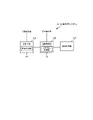
- FIG. 1 is a block diagram showing a hardware configuration of a biological determination system according to a first embodiment.
- the biological determination system 10 includes a processor 11, a RAM (Random Access Memory) 12, a ROM (Read Only Memory) 13, and a storage device 14.
- the biological determination system 10 may further include an input device 15 and an output device 16.
- the processor 11, the RAM 12, the ROM 13, the storage device 14, the input device 15, and the output device 16 are connected via the data bus 17.
- the processor 11 is configured to read a computer program.
- the processor 11 reads a computer program stored in at least one of the RAM 12, the ROM 13, and the storage device 14.
- the processor 11 may read a computer program stored in a computer-readable recording medium by using a recording medium reading device (not shown).
- the processor 11 may acquire (that is, may read) a computer program from a device (not shown) located outside the biometric determination system 10 via a network interface.
- the processor 11 controls the RAM 12, the storage device 14, the input device 15, and the output device 16 by executing the read computer program.
- a functional block for determining whether or not the face is a living body is realized in the processor 11.
- processor 11 a CPU (Central Processing Unit), a GPU (Graphics Processing Unit), an FPGA (field-programmable gate array), a DSP (Demand-Side Platform), and an ASIC (Application) are used. Alternatively, a plurality of them may be used in parallel.
- CPU Central Processing Unit
- GPU Graphics Processing Unit
- FPGA field-programmable gate array
- DSP Demand-Side Platform
- ASIC Application Specific integrated circuit
- the RAM 12 temporarily stores the computer program executed by the processor 11.
- the RAM 12 temporarily stores data temporarily used by the processor 11 while the processor 11 is executing a computer program.
- the RAM 12 may be, for example, a D-RAM (Dynamic RAM).
- the ROM 13 stores a computer program executed by the processor 11.
- the ROM 13 may also store fixed data.
- the ROM 13 may be, for example, a P-ROM (Programmable ROM).
- the storage device 14 stores data stored for a long period of time by the biological determination system 10.
- the storage device 14 may operate as a temporary storage device of the processor 11.
- the storage device 14 may include, for example, at least one of a hard disk device, a magneto-optical disk device, an SSD (Solid State Drive), and a disk array device.
- the input device 15 is a device that receives an input instruction from the user of the biological determination system 10.
- the input device 15 may include, for example, at least one of a keyboard, a mouse and a touch panel.
- the output device 16 is a device that outputs information about the biological determination system 10 to the outside.
- the output device 16 may be a display device (for example, a display) capable of displaying information about the biological determination system 10.
- FIG. 2 is a block diagram showing a functional configuration of the biological determination system according to the first embodiment.
- the biological determination system 10 has a face detection unit 110, a temperature acquisition unit 120, and a biological determination as a processing block or a physical processing circuit for realizing the function. It is provided with a unit 130.
- Each of the face detection unit 110, the temperature acquisition unit 120, and the biological determination unit 130 may be realized by, for example, the processor 11 (see FIG. 1) described above.
- the face detection unit 110 is configured to input, for example, a visible light image captured by a visible light camera.
- the face detection unit 110 is configured to be able to detect the position of the face from the input visible light image.
- the "face” here may be the face of a human or the face of an animal other than a human such as a dog or a snake.
- the face detection unit 110 detects, for example, the position of an area occupied by a face in an image.
- Information about the position of the face detected by the face detection unit 110 is output to the temperature acquisition unit 120.
- the temperature acquisition unit 120 is configured to input, for example, an infrared image captured by a far-infrared camera.
- the temperature acquisition unit 120 is configured to be able to acquire the temperature of a plurality of points on the face from the input infrared image.
- the temperature acquisition unit 120 may acquire the temperature of a plurality of points on the face based on the position of the face detected by the face detection unit 110. Specific examples of the location where the temperature acquisition unit 120 acquires the temperature will be described in detail in other embodiments described later.
- Information about the temperatures of a plurality of locations acquired by the temperature acquisition unit 120 is output to the biological determination unit 130.
- the visible light image input to the face detection unit 110 and the temperature acquisition unit 120 are input so that the temperature acquisition unit 120 can detect the temperature of the face based on the position of the face detected by the face detection unit 110.
- the infrared image to be formed may be an image in which the positional relationship with each other can be understood (specifically, an image in which coordinates can be converted with each other).
- the visible light image and the infrared image may be captured at the same angle of view.
- the visible light image and the infrared image may have their correspondence adjusted by using the pan / tilt / zoom function of the camera or the image conversion.
- the biological determination unit 130 is configured to be able to determine whether or not the face is a living body based on the temperatures of a plurality of locations on the face acquired by the temperature acquisition unit 120. That is, the biological determination unit 130 determines whether the captured face is a biological face or a non-living face (for example, a “spoofed” face using an image, a photograph, a 3D mask, or the like).
- a biological face or a non-living face for example, a “spoofed” face using an image, a photograph, a 3D mask, or the like.
- FIG. 3 is a flowchart showing the operation flow of the biological determination system according to the first embodiment.
- the face detection unit 110 first acquires a visible light image (step S11). Then, the face detection unit 110 detects the position of the face from the acquired visible light image (step S12). The face detection unit 110 outputs information regarding the detected face position to the temperature acquisition unit 120.
- the temperature acquisition unit 120 acquires an infrared image (step S21). Then, the temperature acquisition unit 120 acquires the temperature of a plurality of points on the face from the acquired infrared image (step S22). The temperature acquisition unit 120 may acquire the temperature of a plurality of points on the face by using the position of the face detected by the face detection unit 110.
- the biological determination unit 130 determines whether or not the face belongs to a living body based on the temperatures of a plurality of locations acquired by the temperature acquisition unit 120 (step S23).
- the biological determination unit 130 may output the determination result to the outside of the system.
- the biological determination system 10 it is determined whether or not the face belongs to a biological body based on the temperatures of a plurality of locations.
- the temperatures at a plurality of locations it is possible to more appropriately determine whether or not the face belongs to a living body, as compared with the case where the biological determination is performed based on the temperature at one location on the face. That is, since the temperature of many places is taken into consideration in the biological determination (in other words, the determination is performed using more information), the accuracy of the biological determination can be improved.
- the biological determination system 10 according to the second embodiment will be described with reference to FIGS. 4 and 5.
- the second embodiment is different from the above-mentioned first embodiment only in a part of the configuration and operation, and other parts may be the same as the first embodiment. Therefore, in the following, the parts different from the first embodiment already described will be described in detail, and the description of other overlapping parts will be omitted as appropriate.
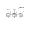
- FIG. 4 is a block diagram showing a functional configuration of the biological determination system according to the second embodiment.
- the same reference numerals are given to the same components as those shown in FIG. 2.
- the biological determination system 10 has a face detection unit 110, a temperature acquisition unit 120, and a biological determination as a processing block or a physical processing circuit for realizing the function. It is provided with a unit 130.
- the biological determination unit 130 according to the second embodiment is configured to include the threshold value determination unit 131.
- the threshold value determination unit 131 determines whether or not each of the temperatures of the plurality of locations acquired by the temperature acquisition unit 120 exceeds a predetermined threshold value.
- the "predetermined threshold value” here is a threshold value for determining whether or not each of the temperatures at a plurality of locations corresponds to the body temperature, and is set in advance as a value of, for example, about 36 ° C to 37 ° C. ing. Further, the predetermined threshold value may be appropriately adjusted based on the image imaging environment (for example, outside air temperature, humidity, etc.). The predetermined threshold value may be appropriately adjusted based on the temperature of the subject acquired within the past predetermined time (for example, within the past 1 hour).
- the predetermined threshold value may be adjusted by using the average value of the temperatures acquired within the predetermined time. Specifically, when the outside air temperature is high or the humidity is high, the predetermined threshold value may be increased. On the contrary, when the outside air temperature is low or the humidity is low, the predetermined threshold value may be lowered.
- the threshold value determination unit 131 is further configured to be able to count the number of temperatures exceeding a predetermined threshold value among a plurality of locations. More specifically, the threshold value determination unit 131 is configured to be able to determine whether or not the temperature exceeding a predetermined threshold value is equal to or higher than a predetermined number.
- the "predetermined number" here is a threshold value for determining a state in which the face exceeds a predetermined threshold value in many places to the extent that it can be determined that the face belongs to a living body, for example, a place where temperature is detected. It is set to a value according to (for example, a majority of detection points, etc.).
- the threshold value determination unit 131 is configured to be able to calculate a predetermined score according to whether or not the temperature at a plurality of locations exceeds the predetermined threshold value and determine whether or not the predetermined score exceeds the score threshold value.
- the "predetermined score” is a score calculated as a higher value as the number of temperatures exceeding a predetermined threshold value among a plurality of locations increases.
- weighting may be performed at each of a plurality of locations. For example, the forehead may be weighted by 2 points, the nose may be weighted by 1 point, the cheeks may be weighted by 0.5 points, and the like.
- the temperature will be the same for living organisms at the target positions of the face such as the right cheek and the left cheek.
- the face is not a living body (that is, spoofing or the like)
- the score is calculated high (for example, 3 points)
- the temperature difference is calculated low (for example, -3 points). You may.
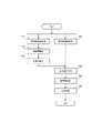
- FIG. 5 is a flowchart showing the operation flow of the biological determination system according to the second embodiment.
- the same reference numerals are given to the same processes as those shown in FIG.
- the face detection unit 110 first acquires a visible light image (step S11). Then, the face detection unit 110 detects the position of the face from the acquired visible light image (step S12). The face detection unit 110 outputs information regarding the detected face position to the temperature acquisition unit 120.
- the temperature acquisition unit 120 acquires an infrared image (step S21). Then, the temperature acquisition unit 120 acquires the temperature of a plurality of points on the face from the acquired infrared image and the position of the face detected by the face detection unit 110 (step S22).
- the threshold value determination unit 131 determines whether or not each of the plurality of temperatures exceeds a predetermined threshold value (step S231). Then, the threshold value determination unit 131 determines whether or not the temperature exceeding the predetermined threshold value is equal to or higher than a predetermined number (step S232). When the temperature exceeding the predetermined threshold value is equal to or higher than a predetermined number (step S232: YES), the biological determination unit 130 determines that the face belongs to a biological body (step S233). On the other hand, when the temperature exceeding the predetermined threshold value is less than a predetermined number (step S232: NO), the biological determination unit 130 determines that the face is not that of the biological body (S234).
- the threshold value determination unit 131 may determine whether or not the predetermined score exceeds the score threshold value. In this case, if the predetermined score exceeds the score threshold value, the biological determination unit 130 may determine that the face belongs to the biological body. Further, if the predetermined score does not exceed the score threshold value, the biological determination unit 130 may determine that the face is not that of the biological body.
- biological determination is performed by comparing the temperatures at a plurality of locations with predetermined threshold values. By doing so, it is possible to easily and accurately determine whether or not the face belongs to a living body based on the temperatures at a plurality of locations.
- the biological determination system 10 according to the third embodiment will be described with reference to FIGS. 6 to 8. It should be noted that the third embodiment differs from the above-mentioned first and second embodiments only in a part of the configuration and operation, and other parts may be the same as those of the first and second embodiments. Therefore, in the following, the parts different from each of the above-described embodiments will be described in detail, and the description of other overlapping parts will be omitted as appropriate.
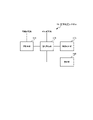
- FIG. 6 is a block diagram showing a functional configuration of the biological determination system according to the third embodiment.
- the same reference numerals are given to the same components as those shown in FIG. 2.
- the biological determination system 10 has a face detection unit 110, a temperature acquisition unit 120, and a biological determination as a processing block or a physical processing circuit for realizing the function. It is provided with a unit 130.
- the face detection unit 110 according to the third embodiment is configured to include a site detection unit 111.
- the temperature acquisition unit 120 according to the third embodiment is configured to include a site temperature acquisition unit 121.
- the part detection unit 111 is configured to be able to detect the position of each part of the face (forehead, cheek, nose, etc.) based on the position of the face detected by the face detection unit 110.
- the site detection unit 111 may, for example, extract a feature amount indicating a facial feature from a face region in an image and detect each part of the face based on the feature amount.
- Information about the position of each part detected by the part detection unit 111 is output to the part temperature acquisition unit 121.
- the part temperature acquisition unit 121 is configured to be able to acquire the temperature of each part of the face detected by the part detection unit 111.
- the part temperature acquisition unit 121 may acquire the temperature of one point in the area occupied by each part as the temperature of the part, or acquire the temperature of a plurality of places in the area occupied by each part as the temperature of the part. You may.
- the temperature of each part acquired by the part temperature acquisition unit 121 is output to the biological determination unit 130.
- FIG. 7 is a flowchart showing the operation flow of the biological determination system according to the third embodiment.
- the same reference numerals are given to the same processes as those shown in FIG.
- the face detection unit 110 first acquires a visible light image (step S11). Then, the face detection unit 110 detects the position of the face from the acquired visible light image (step S12).
- the site detection unit 111 detects the position of the facial site (step S121).
- the site detection unit 111 outputs information regarding the position of the detected facial region to the temperature acquisition unit 120 (more specifically, the site temperature acquisition unit 121).
- the temperature acquisition unit 120 acquires an infrared image (step S21). Then, the part temperature acquisition unit 121 acquires the temperature of the face part from the acquired infrared image and the position of the face part detected by the part detection unit 111 (step S221).
- the biological determination unit 130 determines whether or not the face belongs to a living body based on the temperature of the facial portion acquired by the site temperature acquisition unit 121 (step S23).
- FIG. 8 is a conceptual diagram showing an example of detecting the site temperature by the biological determination system according to the third embodiment.
- the site detection unit 111 detects the forehead portion 51a, the right cheek portion 52a, the left cheek portion 53a, and the nose portion 54a from the face 50a detected from the visible light image, respectively. Then, the site temperature acquisition unit 121 corresponds to each of the forehead portion 51a, the right cheek portion 52a, the left cheek portion 53a, and the nose portion 54a from the face 50b in the infrared image, and the forehead portion 51b and the right cheek portion 52b. , Left cheek 53b, and nose 54b are identified and their temperatures are obtained.
- the forehead portion 51a, the right cheek portion 52a, the left cheek portion 53a, and the nose portion 54a are examples, and the temperature may be obtained from other parts of the face (for example, the punctum).
- the temperature may be acquired at a plurality of locations on one portion of the face.
- the temperature may be obtained separately at the base of the nose, under the nose, at the tip of the nose, etc. at the nose portion 54b.
- the average value of the temperatures acquired at the plurality of points of the nose portion 54b may be acquired as the temperature of the nose portion 54b.
- the threshold value determination unit 131 includes the forehead portion 51b, the right cheek portion 52b, the left cheek portion 53b, and the nose portion 54b. For each region, when the ratio of the area of the region exceeding the predetermined threshold value becomes equal to or more than the predetermined ratio, it may be determined that the temperature of the portion exceeds the predetermined threshold value. Further, the predetermined threshold value in this case may be a different value for each part.
- each part of the face is detected and the temperature is acquired for each part.
- the tendency of body temperature in each part is used to more specifically determine whether or not the body is a living body. It is also possible to do it.
- the fourth embodiment differs from the above-mentioned first to third embodiments only in a part of the configuration and operation, and other parts may be the same as those of the first to third embodiments. Therefore, in the following, the parts different from each of the above-described embodiments will be described in detail, and the description of other overlapping parts will be omitted as appropriate.
- FIG. 9 is a block diagram showing a functional configuration of the biological determination system according to the fourth embodiment.
- the same reference numerals are given to the same components as those shown in FIG.
- the biological determination system 10 has a face detection unit 110, a temperature acquisition unit 120, and a biological determination as a processing block or a physical processing circuit for realizing the function.
- a unit 130 and an attachment determination unit 140 are provided. That is, the biological determination system 10 according to the fourth embodiment is configured to further include an attachment determination unit 140 in addition to the configuration of the biological determination system according to the third embodiment (see FIG. 6).
- the attached object determination unit 140 may be realized by, for example, the processor 11 (see FIG. 1) described above.
- the attached object determination unit 140 is configured to be able to determine the presence or absence of an attached object (for example, a hat, glasses, a mask, etc.) based on the temperatures of a plurality of locations detected by the temperature acquisition unit 120. The specific determination operation in the attachment determination unit 140 will be described in detail later.
- the attached object determination unit 140 may be configured to output information regarding the presence or absence of an attached object to the biological determination unit 130. In this case, the biological determination unit 130 may determine whether or not the face belongs to a living body in consideration of the presence or absence of an attached object.
- FIG. 10 is a flowchart showing the operation flow of the biological determination system according to the fourth embodiment.
- the same reference numerals are given to the same processes as those shown in FIG. 7.
- the face detection unit 110 first acquires a visible light image (step S11). Then, the face detection unit 110 detects the position of the face from the acquired visible light image (step S12).
- the site detection unit 111 detects the position of the facial site (step S121).
- the site detection unit 111 outputs information regarding the position of the detected facial region to the temperature acquisition unit 120.
- the temperature acquisition unit 120 acquires an infrared image (step S21). Then, the part temperature acquisition unit 121 acquires the temperature of the face part from the acquired infrared image and the position of the face part detected by the part detection unit 111 (step S221).
- the attachment determination unit 140 determines the presence or absence of the attachment from the temperature of the face portion (step S24).
- the process of step S24 (that is, the process of determining the attached object) may be executed according to the result of the process of step S221 (that is, the process of acquiring the temperature of the facial portion).
- the attached object determination unit 140 may execute the process of step S24 when there is a temperature of a plurality of places on the face that does not exceed the threshold value. Then, when all the temperatures of the plurality of places on the face exceed the threshold value, the attached object determination unit 140 determines that it is unlikely that the attached object is attached, and omits the process of step S24. You may do it.
- the biological determination unit 130 determines whether or not the face belongs to a living body based on the temperature of the facial portion acquired by the site temperature acquisition unit 121 (step S23).
- FIG. 11 is a flowchart showing the flow of the attachment determination operation of the biological determination system according to the fourth embodiment.
- the attachment determination unit 140 determines whether a low temperature region (that is, a region lower than the body temperature) exists in the upper half of the forehead (that is, a region lower than the body temperature). Step S101). Then, when the low temperature region exists in the upper half of the forehead (step S101: YES), the attachment determination unit 140 detects the hat (step S102). When the low temperature region does not exist in the upper half of the forehead (step S101: NO), the attachment determination unit 140 does not detect the hat (that is, the process of step S102 is omitted).
- the attachment determination unit 140 determines whether or not a low temperature region exists in the lower half of the forehead (step S103). Then, when the low temperature region exists in the lower half of the forehead (step S103: YES), the attachment determination unit 140 detects the spectacles (step S104). When the low temperature region does not exist in the lower half of the forehead (step S103: NO), the attachment determination unit 140 does not detect the spectacles (that is, the process of step S104 is omitted).
- the attachment determination unit 140 determines whether or not a low temperature region exists in the lower half of the nose and the cheek (step S105). Then, when the lower half of the nose and the cheek have a low temperature region (step S105: YES), the attachment determination unit 140 detects the mask (step S106). When the lower half of the nose and the cheek do not have a low temperature region (step S105: NO), the attachment determination unit 140 does not detect the mask (that is, the process of step S106 is omitted).
- the operation of detecting the hat, the glasses, and the mask has been described, but when detecting other attachments, the temperature of the region corresponding to the attachments is low as in the above-mentioned operation. It suffices to determine whether or not it is an area.
- FIG. 12 is a conceptual diagram showing an example of a change in the temperature acquisition region depending on the presence or absence of an attached object.
- the part of the face from which the temperature is acquired may be changed according to the determination result of the attachment determination unit 140. That is, the temperature acquisition unit 120 may reacquire the temperature of the facial portion based on the determination result of the attachment determination unit 140.
- the temperature of the forehead, both cheeks, the nose, and the punctum may be obtained from the face 601 without an attachment (see 606).
- the temperatures of the forehead, cheeks, nose, and punctum may be obtained from the face 602 when the mask is worn (see 607). If the mask is detected, the temperature acquisition positions of both cheeks and nose may be shifted so as to avoid the mask.
- the temperatures of both cheeks and nose may be obtained from the face 603 when the hat and mask are worn (see 608).
- the temperatures of both cheeks and nose may be obtained from the face 604 when the hat and glasses are worn (see 609).
- the temperatures of both cheeks and nose may be obtained from the face 605 when the hat, glasses and mask are worn (see 610).
- the target person may be notified (for example, notification by display, voice, etc.) according to the determination result of the attachment determination unit 140.
- a notification may be given to urge the subject to remove the hat or sunglasses.
- a notification may be given to urge the subject to face the camera while wearing the mask. If the subject is not wearing a mask, a notification may be given to encourage them to wear a mask.
- the biological determination system 10 can determine the presence / absence of an attached object from the temperatures of a plurality of points on the face. In addition, it is possible to appropriately determine whether or not the face is a living body in consideration of the presence of the attached object, such as changing the temperature acquisition position according to the position of the attached object.
- the biological determination system 10 according to the fifth embodiment will be described with reference to FIGS. 13 and 14. It should be noted that the fifth embodiment differs from the first to fourth embodiments described above only in a part of the configuration and operation, and other parts may be the same as those of the first to fourth embodiments. Therefore, in the following, the parts different from each of the above-described embodiments will be described in detail, and the description of other overlapping parts will be omitted as appropriate.
- FIG. 13 is a block diagram showing a functional configuration of the biological determination system according to the fifth embodiment.
- the same reference numerals are given to the same components as those shown in FIG. 9.
- the biological determination system 10 has a face detection unit 110, a temperature acquisition unit 120, and a biological determination as a processing block or a physical processing circuit for realizing the function.
- a unit 130, an attachment determination unit 140, and an attachment detection unit 150 are provided. That is, the biological determination system 10 according to the fifth embodiment is configured to further include an attachment detection unit 150 in addition to the configuration of the biological determination system according to the fourth embodiment (see FIG. 9).
- the attached object detection unit 150 may be realized by, for example, the processor 11 (see FIG. 1) described above.
- the attachment detection unit 150 is configured to be able to detect an attachment (that is, an attachment that can be determined by the attachment determination unit 140 described in the fourth embodiment) from the visible light image. As for the method of detecting the attached object from the image, the existing technique can be appropriately adopted, and therefore detailed description thereof is omitted here. Information about the attached object detected by the attached object detecting unit 150 is output to the attached object determination unit 140.
- FIG. 14 is a flowchart showing the operation flow of the biological determination system according to the fifth embodiment.
- the same reference numerals are given to the same processes as those shown in FIG. 14.
- the face detection unit 110 first acquires a visible light image (step S11). Then, the face detection unit 110 detects the position of the face from the acquired visible light image (step S12).
- the site detection unit 111 detects the position of the facial site (step S121).
- the site detection unit 111 outputs information regarding the position of the detected facial region to the temperature acquisition unit 120.
- the attachment detection unit 150 detects the attachment from the visible light image (step S13).
- the attachment detection unit 150 outputs information about the detected attachment to the attachment determination unit 140.
- the temperature acquisition unit 120 acquires an infrared image (step S21). Then, the part temperature acquisition unit 121 acquires the temperature of the face part from the acquired infrared image and the position of the face part detected by the part detection unit 111 (step S221).
- the attachment determination unit 140 determines the presence or absence of the attachment from the temperature of the face portion (step S24). Then, the attachment determination unit 140 compares the information regarding the presence / absence of the attachment obtained as the determination result with the information regarding the attachment obtained as the detection result of the attachment detection unit 150 (step S25). More specifically, the attachment determination unit 140 compares the determination result of the attachment with the detection result of the attachment, and determines whether or not they match each other.
- the biological determination unit 130 determines whether or not the face belongs to a living body based on the temperature of the facial portion acquired by the site temperature acquisition unit 121 (step S23). The biological determination unit 130 determines whether or not the face is a living body in consideration of the determination result regarding the presence or absence of the attachment by the attachment determination unit 140 and the comparison result of the information regarding the attachment. May be good.
- the attachment determination result 140 (that is, the attachment determination result based on the temperature) and the attachment are determined.
- the detection result of the attachment by the detection unit 150 (that is, the detection result of the attachment based on the image) is compared with each other.
- the above-mentioned comparison result of the information on the attached object may be used to make the determination result of the attached object more accurate. For example, even if the attachment determination unit 140 determines that there is an attachment, if the attachment detection unit 150 does not detect the attachment, the attachment determination unit 140 determines that the attachment is present. If it does not exist, the determination result may be changed (or the presence or absence of the attached object may be determined again). Similarly, even if it is determined by the attachment determination unit 140 that there is no attachment, if the attachment detection unit 150 detects the attachment, the attachment determination unit 140 may use the attachment determination unit 140. If there is, the determination result may be changed (or the presence or absence of the attached object may be determined again). By doing so, the accuracy of the determination result by the attached object determination unit 140 can be improved.
- the comparison result of the above-mentioned information on the attached object may be used for the determination of the biological determination unit 130. For example, even if the attachment determination unit 140 determines that there is an attachment, if the attachment detection unit 150 does not detect the attachment, the attachment is present even though there is an attachment. It may be determined that there is a low temperature region that may be misidentified as, and the biological determination unit 130 may determine that the face is not of the living body (that is, some kind of "spoofing" has been performed). Further, even if the attachment determination unit 140 determines that there is no attachment, if the attachment detection unit 150 detects the attachment, the temperature is high despite the presence of the attachment. The biological determination unit 130 may determine that the face is not a biological one (that is, some kind of "spoofing" has been performed). By doing so, the accuracy of the determination result in the biological determination unit 130 can be improved.
- FIG. 15 is a block diagram showing a functional configuration of the biological determination system according to the sixth embodiment.
- the same reference numerals are given to the same components as those shown in FIG.
- the biological determination system 10 has a face detection unit 110, a temperature acquisition unit 120, and a biological determination as a processing block or a physical processing circuit for realizing the function. It is provided with a unit 130.
- the biological determination unit 130 according to the sixth embodiment is configured to include a temperature comparison unit 132.
- the temperature comparison unit 132 is configured to be able to compare the temperatures of a plurality of faces acquired by the temperature acquisition unit 120 with each other.
- the temperature comparison unit 132 may be configured to be able to determine, for example, not only whether the temperature at a plurality of locations is high or low, but also whether or not the relationship between the temperatures at the plurality of locations satisfies a predetermined rule.
- the "predetermined rule” here corresponds to the temperature tendency depending on the part (position) of the face, for example, whether the temperature of the forehead is higher than the temperature of the nose, the temperature of the right cheek and the temperature of the left cheek.
- the predetermined rule may be a combination of a plurality of rules including those exemplified above.
- the comparison result by the temperature comparison unit 132 is configured to be taken into consideration in determining whether or not the face in the biological determination unit 130 belongs to a living body.
- FIG. 16 is a flowchart showing the operation flow of the biological determination system according to the sixth embodiment.
- the same reference numerals are given to the same processes as those shown in FIG. 7.
- the face detection unit 110 first acquires a visible light image (step S11). Then, the face detection unit 110 detects the position of the face from the acquired visible light image (step S12).
- the site detection unit 111 detects the position of the facial site (step S121).
- the site detection unit 111 outputs information regarding the position of the detected facial region to the temperature acquisition unit 120.
- the temperature acquisition unit 120 acquires an infrared image (step S21). Then, the part temperature acquisition unit 121 acquires the temperature of the face part from the acquired infrared image and the position of the face part detected by the part detection unit 111 (step S221).
- the temperature comparison unit 132 compares the temperatures of the respective parts with each other (step S235). Then, the temperature comparison unit 132 determines whether or not the comparison result satisfies the predetermined rule (step S236). When the comparison result satisfies the predetermined rule (step S236: YES), the biological determination unit 130 determines that the face belongs to the living body (step S237). On the other hand, when the comparison result does not satisfy the predetermined rule (step S236: NO), the biological determination unit 130 determines that the face is not that of the biological body (S238).
- the temperatures of a plurality of faces are compared with each other. In this way, it is possible to appropriately determine whether or not the face is a living body based on the relationship between the temperatures of a plurality of parts of the face.
- the biological determination system 10 according to the seventh embodiment will be described with reference to FIGS. 17 to 19. It should be noted that the seventh embodiment differs from the above-mentioned first to sixth embodiments only in a part of the configuration and operation, and other parts may be the same as those of the first to sixth embodiments. Therefore, in the following, the parts different from each of the above-described embodiments will be described in detail, and the description of other overlapping parts will be omitted as appropriate.
- FIG. 17 is a block diagram showing a functional configuration of the biological determination system according to the seventh embodiment.
- the same reference numerals are given to the same components as those shown in FIG. 2.
- the biological determination system 10 has a face detection unit 110, a temperature acquisition unit 120, and a biological determination as a processing block or a physical processing circuit for realizing the function.
- a unit 130 and a display unit 160 are provided. That is, the biological determination system 10 according to the fifth embodiment is configured to further include a display unit 160 in addition to the configuration of the biological determination system according to the first embodiment (see FIG. 2).
- the display unit 160 may be realized by, for example, the output device 16 (see FIG. 1) described above.
- the display unit 160 is configured to be able to display the temperatures of a plurality of faces acquired by the temperature acquisition unit 120.
- the display unit 160 may be configured so that its display mode can be changed by the operation of a system user (for example, a system user, a system administrator, or the like). Specific examples of the display mode in the display unit 160 will be described in detail below.
- FIG. 18 is a diagram showing a display example (No. 1) by the biological determination system according to the seventh embodiment.
- FIG. 19 is a diagram showing a display example (No. 2) by the biological determination system according to the seventh embodiment.
- the display unit 160 of the biological determination system 10 may display the acquired temperature superimposed on the image of the face 50.
- the temperature of the forehead "36.8 ° C.” is superimposed on the forehead portion of the face 50.
- the temperature of the right cheek “36.7 ° C.” is superimposed on the right cheek portion of the face 50.
- the temperature of the left cheek “36.6 ° C.” is superimposed on the left cheek portion of the face 50.
- the nose temperature "36.5 ° C.” is superimposed on the nose portion of the face 50.
- the temperature of each part displayed in FIG. 18 may be switched between display and non-display for each part by the operation of the system user. Further, the temperature of each part may be changed in color or highlighted according to the numerical value. For example, a temperature exceeding a predetermined threshold value may be displayed in red or in bold characters.
- the display unit 160 of the biological determination system 10 may display a list of the temperature of each unit and the determination result (for example, the determination result by the threshold value determination unit 131). ..
- the temperature of the forehead is "36.8”, and the determination result is displayed as "OK (for example, exceeding the threshold value)”.
- the temperature of the right cheek is "36.7 ° C.”, and the determination result is displayed as "OK”.
- the temperature of the nose is "30.5 ° C.”, and the determination result is displayed as "NG (for example, less than the threshold value)”.
- the temperature of the left cheek is "22.8 ° C.”, and the determination result is displayed as "NG”.
- each item shown in FIG. 19 may be rearranged and displayed as appropriate according to a predetermined condition.
- each item may be rearranged and displayed in descending order of temperature, or may be rearranged and displayed so that the item whose determination result is "OK" comes to the top.
- the predetermined conditions that determine the display order of each item may be configured to be changeable by the operation of the system user. Further, each item may be changed in color or highlighted according to its contents. For example, an item whose determination result is OK may be displayed in red or surrounded by a frame.
- the temperatures of a plurality of faces acquired by the temperature acquisition unit 120 are displayed by the display unit 160. Therefore, it is possible to visually present the temperature of each part of the face to the user.
- the target for presenting various information by the display unit 160 may be a target person whose face has been imaged, or may be a guard or a guard who uses the system. However, if you do not want the target person to know which part of the face you are measuring the temperature, do not display it to the target person, but only to the guards and guards. You may.
- the target person may be displayed only with the highest temperature of each part, while the observer or the like may be displayed with the temperature of all parts.
- the biological determination system 10 according to the eighth embodiment will be described with reference to FIGS. 20 and 21. It should be noted that the eighth embodiment differs from the above-mentioned first to seventh embodiments only in a part of the configuration and operation, and other parts may be the same as those of the first to seventh embodiments. Therefore, in the following, the parts different from each of the above-described embodiments will be described in detail, and the description of other overlapping parts will be omitted as appropriate.
- FIG. 20 is a block diagram showing a functional configuration of the biological determination system according to the eighth embodiment.
- the same reference numerals are given to the same components as those shown in FIG.
- the biological determination system 10 has a face detection unit 110, a temperature acquisition unit 120, and a biological determination as a processing block or a physical processing circuit for realizing the function.
- a unit 130 and a heat source detection unit 170 are provided. That is, the biological determination system 10 according to the eighth embodiment is configured to further include a heat source detection unit 170 in addition to the configuration of the biological determination system according to the second embodiment (see FIG. 4).
- the heat source detection unit 170 may be realized by, for example, the processor 11 (see FIG. 1) described above.
- the heat source detection unit 170 is configured to be able to detect a heat source having a predetermined shape from an infrared image.
- the "heat source having a predetermined shape” here is a heat source that can be used for "spoofing" (for example, a heat source for giving a photo or the like a temperature similar to body temperature), for example, a body warmer, a smartphone, a tablet, or the like. Can be mentioned. These heat sources can be detected in an infrared image, for example, as a rectangular unnatural high temperature region.
- the heat source detection unit 170 is configured to be able to execute an operation that makes it difficult to determine that the face belongs to a living body when a heat source having a predetermined shape is detected.
- the heat source detection unit 170 may make it difficult to determine that the face belongs to a living body by, for example, raising the threshold value of the threshold value determination unit 131.
- FIG. 21 is a flowchart showing the operation flow of the biological determination system according to the seventh embodiment.
- the same reference numerals are given to the same processes as those shown in FIG.
- the face detection unit 110 first acquires a visible light image (step S11). Then, the face detection unit 110 detects the position of the face from the acquired visible light image (step S12). The face detection unit 110 outputs information regarding the detected face position to the temperature acquisition unit 120.
- the temperature acquisition unit 120 acquires an infrared image (step S21). Then, the temperature acquisition unit 120 acquires the temperature of a plurality of points on the face from the acquired infrared image and the position of the face detected by the face detection unit 110 (step S22).
- the heat source detection unit 170 detects a heat source having a predetermined shape from the temperatures of a plurality of places on the face (step S26).
- the heat source detection unit 170 may detect a heat source having a predetermined shape from the infrared image acquired by the temperature acquisition unit 120.
- step S26 YES
- the heat source detection unit 170 is changed to raise the predetermined threshold value used by the threshold value determination unit 131 (step S27).
- step S26 when the heat source having a predetermined shape is not detected (step S26: NO), the heat source detection unit 170 does not change the predetermined threshold value used by the threshold value determination unit 131 (that is, the process of step S27 is omitted).
- the threshold value determination unit 131 determines whether or not each of the plurality of temperatures exceeds a predetermined threshold value (if the value is changed in step S27, the threshold value after the change) (step S231). Then, the threshold value determination unit 131 determines whether or not the temperature exceeding the predetermined threshold value is equal to or higher than a predetermined number (step S232). When the temperature exceeding the predetermined threshold value is equal to or higher than a predetermined number (step S232: YES), the biological determination unit 130 determines that the face belongs to a biological body (step S233). On the other hand, when the temperature exceeding the predetermined threshold value is less than a predetermined number (step S232: NO), the biological determination unit 130 determines that the face is not that of the biological body (S234).
- the biological determination system 10 detects a heat source having a predetermined shape. Therefore, it is possible to detect "spoofing" using a heat source and make it difficult to determine that the face belongs to a living body in such a case.
- face authentication may be difficult to succeed when a heat source having a predetermined shape is detected (for example,).
- the threshold value used for face matching may be changed).
- ⁇ 9th embodiment> The biological determination system 10 according to the ninth embodiment will be described with reference to FIGS. 22 and 23. It should be noted that the ninth embodiment differs from the above-mentioned first to eighth embodiments only in a part of the configuration and operation, and other parts may be the same as those of the first to eighth embodiments. Therefore, in the following, the parts different from each of the above-described embodiments will be described in detail, and the description of other overlapping parts will be omitted as appropriate.
- FIG. 22 is a block diagram showing a functional configuration of the biological determination system according to the ninth embodiment.
- the same reference numerals are given to the same components as those shown in FIG. 2.
- the biological determination system 10 has a face detection unit 110, a temperature acquisition unit 120, and a biological determination as a processing block or a physical processing circuit for realizing the function.
- a unit 130 and a face recognition unit 180 are provided. That is, the biological determination system 10 according to the eighth embodiment is configured to further include a face recognition unit 180 in addition to the configuration of the biological determination system according to the first embodiment (see FIG. 2).
- the face recognition unit 180 may be realized by, for example, the processor 11 (see FIG. 1) described above.
- the face recognition unit 180 collates the face detected from the image with the face registered in advance, and determines whether or not the target whose face is imaged is a registered person or not.
- the process to be performed) is configured to be executable.
- the face recognition unit 180 may extract a facial feature amount from the face detected by the face detection unit 110 and perform face recognition using the feature amount.
- existing techniques can be appropriately adopted, and therefore detailed description thereof will be omitted here.
- the face authentication unit 180 can output the final authentication result in consideration of the determination result (that is, whether or not the face is a living body) by the biological determination system 10 according to each of the above-described embodiments. It is configured.
- FIG. 23 is a flowchart showing the operation flow of the biological determination system according to the ninth embodiment.
- the same reference numerals are given to the same processes as those shown in FIG. 23.
- the face detection unit 110 first acquires a visible light image (step S11). Then, the face detection unit 110 detects the position of the face from the acquired visible light image (step S12). The face detection unit 110 outputs information regarding the detected face position to the temperature acquisition unit 120. After that, the face recognition unit 180 executes face matching using the information about the face detected by the face detection unit 110 (step S14).
- the temperature acquisition unit 120 acquires an infrared image (step S21). Then, the temperature acquisition unit 120 acquires the temperature of a plurality of points on the face from the acquired infrared image and the position of the face detected by the face detection unit 110 (step S22). After that, the biological determination unit 130 determines whether or not the face belongs to a living body based on the temperatures of the plurality of locations acquired by the temperature acquisition unit 120 (step S23). The biological determination unit 130 outputs the determination result to the face recognition unit 180.
- the face recognition unit 180 outputs the face recognition authentication result in consideration of the face verification result in step S14 and the biometric determination result in step S23 (step S31).
- the face recognition unit 180 may output the result that the face recognition is successful, for example, when the face matching is successful and the face is determined to be a living body.
- the face recognition unit 180 may output the result that the face recognition has failed when the face matching fails or when it is determined that the face is not a living body. Further, when the face authentication fails, the face authentication unit 180 may repeat the series of processes shown in FIG. 23 again (that is, retry the authentication process).
- the determination result of the biological determination unit 130 (that is, the determination result of whether or not the face belongs to a living body) is face recognition. Used for. Therefore, it is possible to detect a user who attempts to detect face recognition fraudulently by detecting "spoofing" or the like in face recognition.
- the biological determination system is based on a face detecting means for detecting the position of the face from an image including a face, a temperature acquiring means for acquiring the temperature at a plurality of places on the face, and the temperature at the plurality of places.
- the biological determination system is characterized by comprising a biological determination means for determining whether or not the face belongs to a living body.
- the biological determination means determines that the face is a biological one when the number of temperatures exceeding a predetermined threshold value exceeds a predetermined number among the plurality of temperatures.
- the biological determination system according to the appendix 3 further includes a site detecting means for detecting the positions of a plurality of parts on the face based on the positions of the face, and the temperature acquiring means includes each of the positions of the plurality of parts.
- the biological determination system according to Appendix 5 further includes an attachment detecting means for detecting the attached object from the image, and the biological determination means includes information on the attached object detected by the attached object detecting means and the said.
- the biological determination system according to Appendix 4 wherein the face is determined whether or not the face is of a living body by comparing with the information about the attached object determined by the attached object determination unit.
- the biological determination system according to Appendix 6 is characterized in that the biological determination means compares the temperatures of the plurality of locations with each other to determine whether or not the face belongs to a living body.
- the biological determination system according to any one of the above.
- the biological determination system according to Appendix 8 further includes a heat source detecting means for detecting a heat source having a predetermined shape on the face based on the temperatures at the plurality of locations, and the biological determination means detects the heat source having the predetermined shape.
- the biological determination system according to any one of Supplementary note 1 to 7, wherein the face is difficult to be determined to belong to a living body.
- the biological determination method according to Appendix 9 detects the position of the face from an image including the face, acquires the temperatures of a plurality of points on the face, and based on the temperatures of the plurality of points, the face is a living body. It is a biological determination method characterized by determining whether or not it exists.
- the computer program according to the appendix 10 detects the position of the face from the image including the face, acquires the temperatures of the plurality of places on the face, and the face is a living body based on the temperatures of the plurality of places. It is a computer program characterized by operating a computer so as to determine whether or not it is.
- Appendix 11 The recording medium described in Appendix 11 is a recording medium characterized in that the computer program described in Appendix 10 is recorded.
- Biometric determination system 11
- Processor 110 Face detection unit 111
- Site detection unit 120
- Temperature acquisition unit 121 Part temperature acquisition unit 130
- Biometrics determination unit 131
- Threshold determination unit 132
- Temperature comparison unit 140
- Equipment determination unit 150
- Equipment detection unit 160
- Display unit 170 Heat source Detection unit 180 Face recognition unit
Abstract
生体判定システム(10)は、顔を含む画像から顔の位置を検出する顔検出手段(110)と、顔における複数箇所の温度を取得する温度取得手段(120)と、複数箇所の温度に基づいて、顔が生体のものであるか否かを判定する生体判定手段(130)とを備える。このような生体判定システムによれば、画像に含まれる顔が生体のものであるか否かを適切に検出することができる。
Description
この開示は、生体を判定する生体判定システム、生体判定方法、及びコンピュータプログラムの技術分野に関する。
この種のシステムとして、体温を検出して生体判定(言い換えれば、なりすまし判定)を行うものが知られている。例えば特許文献1では、赤外線温度画像から顔における熱情報を判定し、顔から熱を検知できない場合に生体認証が失敗したと出力する技術が開示されている。
その他の関連する技術として、例えば特許文献2では、近赤外画像からマスクや眼鏡を検出する技術が開示されている。特許文献3では、サーモグラフィー機能により取得した体温計測値に基づいて、マスク着用であることを検出する技術が開示されている。
この開示は、上述した関連する技術を改善することを目的とする。
この開示の生体判定システムの一の態様は、顔を含む画像から前記顔の位置を検出する顔検出手段と、前記顔における複数箇所の温度を取得する温度取得手段と、前記複数箇所の温度に基づいて、前記顔が生体のものであるか否かを判定する生体判定手段とを備える。
この開示の生体判定方法の一の態様は、顔を含む画像から前記顔の位置を検出し、前記顔における複数箇所の温度を取得し、前記複数箇所の温度に基づいて、前記顔が生体のものであるか否かを判定する。
この開示のコンピュータプログラムの一の態様は、顔を含む画像から前記顔の位置を検出し、前記顔における複数箇所の温度を取得し、前記複数箇所の温度に基づいて、前記顔が生体のものであるか否かを判定するようにコンピュータを動作させる。
以下、図面を参照しながら、生体判定システム、生体判定方法、及びコンピュータプログラムの実施形態について説明する。
<第1実施形態>
第1実施形態に係る生体判定システムについて、図1から図3を参照して説明する。
第1実施形態に係る生体判定システムについて、図1から図3を参照して説明する。
(ハードウェア構成)
まず、図1を参照しながら、第1実施形態に係る生体判定システムのハードウェア構成について説明する。図1は、第1実施形態に係る生体判定システムのハードウェア構成を示すブロック図である。
まず、図1を参照しながら、第1実施形態に係る生体判定システムのハードウェア構成について説明する。図1は、第1実施形態に係る生体判定システムのハードウェア構成を示すブロック図である。
図1に示すように、第1実施形態に係る生体判定システム10は、プロセッサ11と、RAM(Random Access Memory)12と、ROM(Read Only Memory)13と、記憶装置14とを備えている。生体判定システム10は更に、入力装置15と、出力装置16とを備えていてもよい。プロセッサ11と、RAM12と、ROM13と、記憶装置14と、入力装置15と、出力装置16とは、データバス17を介して接続されている。
プロセッサ11は、コンピュータプログラムを読み込むように構成されている。例えば、プロセッサ11は、RAM12、ROM13及び記憶装置14のうちの少なくとも一つが記憶しているコンピュータプログラムを読み込む。或いは、プロセッサ11は、コンピュータで読み取り可能な記録媒体が記憶しているコンピュータプログラムを、図示しない記録媒体読み取り装置を用いて読み込んでもよい。プロセッサ11は、ネットワークインタフェースを介して、生体判定システム10の外部に配置される不図示の装置からコンピュータプログラムを取得してもよい(つまり、読み込んでもよい)。プロセッサ11は、読み込んだコンピュータプログラムを実行することで、RAM12、記憶装置14、入力装置15及び出力装置16を制御する。本実施形態では特に、プロセッサ11が読み込んだコンピュータプログラムを実行すると、プロセッサ11内には、顔が生体のものであるか否かを判定するための機能ブロックが実現される。また、プロセッサ11として、CPU(Central Processing Unit)、GPU(Graphics Processing Unit)、FPGA(field-programmable gate array)、DSP(Demand-Side Platform)、ASIC(Application Specific Integrated Circuit)のうち一つを用いてもよいし、複数を並列で用いてもよい。
RAM12は、プロセッサ11が実行するコンピュータプログラムを一時的に記憶する。RAM12は、プロセッサ11がコンピュータプログラムを実行している際にプロセッサ11が一時的に使用するデータを一時的に記憶する。RAM12は、例えば、D-RAM(Dynamic RAM)であってもよい。
ROM13は、プロセッサ11が実行するコンピュータプログラムを記憶する。ROM13は、その他に固定的なデータを記憶していてもよい。ROM13は、例えば、P-ROM(Programmable ROM)であってもよい。
記憶装置14は、生体判定システム10が長期的に保存するデータを記憶する。記憶装置14は、プロセッサ11の一時記憶装置として動作してもよい。記憶装置14は、例えば、ハードディスク装置、光磁気ディスク装置、SSD(Solid State Drive)及びディスクアレイ装置のうちの少なくとも一つを含んでいてもよい。
入力装置15は、生体判定システム10のユーザからの入力指示を受け取る装置である。入力装置15は、例えば、キーボード、マウス及びタッチパネルのうちの少なくとも一つを含んでいてもよい。
出力装置16は、生体判定システム10に関する情報を外部に対して出力する装置である。例えば、出力装置16は、生体判定システム10に関する情報を表示可能な表示装置(例えば、ディスプレイ)であってもよい。
(機能的構成)
次に、図2を参照しながら、第1実施形態に係る生体判定システム10の機能的構成について説明する。図2は、第1実施形態に係る生体判定システムの機能的構成を示すブロック図である。
次に、図2を参照しながら、第1実施形態に係る生体判定システム10の機能的構成について説明する。図2は、第1実施形態に係る生体判定システムの機能的構成を示すブロック図である。
図2に示すように、第1実施形態に係る生体判定システム10は、その機能を実現するための処理ブロック又は物理的な処理回路として、顔検出部110と、温度取得部120と、生体判定部130とを備えている。なお、顔検出部110、温度取得部120、及び生体判定部130の各々は、例えば上述したプロセッサ11(図1参照)によって実現されてよい。
顔検出部110は、例えば可視光カメラで撮像された可視光画像が入力されるように構成されている。そして、顔検出部110は、入力される可視光画像から顔の位置を検出可能に構成されている。なお、ここでの「顔」は、人の顔であってもよいし、犬や蛇等の人以外の動物の顔であってもよい。顔検出部110は、例えば画像において顔が占める領域の位置を検出する。顔検出部110による具体的な顔の検出手法については、既存の技術を適宜採用できるため、詳しい説明は省略するものとする。顔検出部110で検出された顔の位置に関する情報は、温度取得部120に出力される構成となっている。
温度取得部120は、例えば遠赤外線カメラで撮像された赤外線画像が入力されるように構成されている。そして、温度取得部120は、入力される赤外線画像から、顔の複数箇所の温度を取得可能に構成されている。温度取得部120は、顔検出部110で検出された顔の位置に基づいて、顔の複数箇所の温度を取得するようにしてもよい。温度取得部120が温度を取得する箇所の具体例については、後述する他の実施形態において詳しく説明する。温度取得部120で取得された複数箇所の温度に関する情報は、生体判定部130に出力される構成となっている。
なお、温度取得部120が、顔検出部110で検出された顔の位置に基づいて顔の温度を検出できるように、顔検出部110に入力される可視光画像と、温度取得部120に入力される赤外線画像とは、互いの位置関係が分かるもの(具体的には、互いに座標変換可能なもの)とされていてもよい。例えば、可視光画像と赤外線画像とは、同画角で撮像されていてもよい。或いは、可視光画像及び赤外線画像は、カメラのパン・チルト・ズーム機能や画像変換を利用して対応関係が調整されたものであってもよい。
生体判定部130は、温度取得部120で取得された顔の複数箇所の温度に基づいて、顔が生体であるか否かを判定可能に構成されている。即ち、生体判定部130は、撮像された顔が生体の顔であるか、非生体の顔(例えば、画像、写真、3Dマスク等による“なりすまし”の顔)であるかを判定する。なお、生体判定部130による具体的な判定処理の内容については、後述する他の実施形態において詳しく説明する。
(動作の流れ)
次に、図3を参照しながら、第1実施形態に係る生体判定システム10の動作の流れについて説明する。図3は、第1実施形態に係る生体判定システムの動作の流れを示すフローチャートである。
次に、図3を参照しながら、第1実施形態に係る生体判定システム10の動作の流れについて説明する。図3は、第1実施形態に係る生体判定システムの動作の流れを示すフローチャートである。
図3に示すように、第1実施形態に係る生体判定システム10の動作が開始されると、まず顔検出部110が可視光画像を取得する(ステップS11)。そして、顔検出部110は、取得した可視光画像から顔の位置を検出する(ステップS12)。顔検出部110は、検出した顔の位置に関する情報を温度取得部120に出力する。
一方、温度取得部120は赤外線画像を取得する(ステップS21)。そして、温度取得部120は、取得した赤外線画像から、顔の複数箇所の温度を取得する(ステップS22)。温度取得部120は、顔検出部110で検出された顔の位置を用いて、顔の複数箇所の温度を取得してもよい。
続いて、生体判定部130が、温度取得部120で取得された複数箇所の温度に基づいて、顔が生体のものであるか否かを判定する(ステップS23)。生体判定部130は、判定結果をシステム外部に出力するようにしてもよい。
(技術的効果)
次に、第1実施形態に係る生体判定システム10によって得られる技術的効果について説明する。
次に、第1実施形態に係る生体判定システム10によって得られる技術的効果について説明する。
図1から図3で説明したように、第1実施形態に係る生体判定システム10では、複数箇所の温度に基づいて顔が生体のものであるか否かが判定される。このように複数箇所の温度を用いれば、顔の1箇所の温度に基づいて生体判定をする場合と比較して、より適切に顔が生体のものであるか否かを判定することができる。即ち、生体判定により多くの箇所の温度が考慮される(言い換えれば、より多くの情報を用いて判定が行われる)ため、生体判定の精度を上げることができる。例えば、生体でない顔の1箇所が生体と推定されるような温度であったとしても、他の箇所が生体と推定されない温度であれば、正しく生体でないと判定できる。
<第2実施形態>
第2実施形態に係る生体判定システム10について、図4及び図5を参照して説明する。なお、第2実施形態は、上述した第1実施形態と一部の構成及び動作が異なるのみであり、その他の部分については、第1実施形態と同様であってよい。このため、以下では、既に説明した第1実施形態と異なる部分について詳しく説明し、他の重複する部分については適宜説明を省略するものとする。
第2実施形態に係る生体判定システム10について、図4及び図5を参照して説明する。なお、第2実施形態は、上述した第1実施形態と一部の構成及び動作が異なるのみであり、その他の部分については、第1実施形態と同様であってよい。このため、以下では、既に説明した第1実施形態と異なる部分について詳しく説明し、他の重複する部分については適宜説明を省略するものとする。
(機能的構成)
まず、図4を参照しながら、第2実施形態に係る生体判定システム10の機能的構成について説明する。図4は、第2実施形態に係る生体判定システムの機能的構成を示すブロック図である。なお、図4では、図2で示す構成要素と同様の要素に同一の符号を付している。
まず、図4を参照しながら、第2実施形態に係る生体判定システム10の機能的構成について説明する。図4は、第2実施形態に係る生体判定システムの機能的構成を示すブロック図である。なお、図4では、図2で示す構成要素と同様の要素に同一の符号を付している。
図4に示すように、第2実施形態に係る生体判定システム10は、その機能を実現するための処理ブロック又は物理的な処理回路として、顔検出部110と、温度取得部120と、生体判定部130とを備えている。そして特に、第2実施形態に係る生体判定部130は、閾値判定部131を備えて構成されている。
閾値判定部131は、温度取得部120で取得された複数箇所の温度の各々について、所定閾値を超えているか否かを判定する。なお、ここでの「所定閾値」は、複数箇所の温度の各々が体温に相当する温度であるか否かを判定するための閾値であり、例えば36℃~37℃程度の値として予め設定されている。また、所定閾値は、画像の撮像環境(例えば、外気温や湿度等)に基づいて適宜調整されてもよい。所定閾値は、過去所定時間内(例えば、過去1時間以内)に取得してきた対象者の温度に基づいて適宜調整されてもよい。この場合、所定時間内に取得した温度の平均値等を用いて、所定閾値を調整するようにしてもよい。具体的には、外気温が高い場合や湿度が高い場合には、所定閾値を上げるようにしてもよい。逆に、外気温が低い場合や湿度が低い場合には、所定閾値を下げるようにしてもよい。
閾値判定部131は更に、複数箇所の温度のうち、所定閾値を超えたものの数をカウント可能に構成されている。より具体的には、閾値判定部131は、所定閾値を超えた温度が所定数以上であるか否かを判定可能に構成されている。なお、ここでの「所定数」は、顔が生体のものであると判定できる程度に、多くの箇所で所定閾値を超えている状態を判定するための閾値であり、例えば温度を検出する箇所に応じた値(例えば、検出箇所の過半数等)に設定されている。また、閾値判定部131は、複数箇所の温度が所定閾値を超えたか否かに応じて所定スコアを算出して、所定スコアがスコア閾値を超えてるか否かを判定可能に構成されていてもよい。ここでの「所定スコア」は、複数箇所の温度のうち所定閾値を超えたものが多くなるほど高い値として算出されるスコアである。ただし、所定スコアの算出については、複数箇所の各々で重み付けを行ってもよい。例えば、額は2ポイント、鼻は1ポイント、頬は0.5ポイント等の重み付けを行ってもよい。ちなみに、右頬及び左頬のように顔の対象位置にある箇所については、生体であれば同じような温度となる可能性が高い。一方で、顔が生体ではない(即ち、なりすまし等である)場合、右頬と左頬との温度に差が生ずると考えられる。このような状況を想定して、例えば両頬の温度差が小さければスコアを高く算出し(例えば3ポイント)、温度差が大きければスコアを低く算出する(例えば、-3ポイント)とするようにしてもよい。
(動作の流れ)
次に、図5を参照しながら、第2実施形態に係る生体判定システム10の動作の流れについて説明する。図5は、第2実施形態に係る生体判定システムの動作の流れを示すフローチャートである。なお、図5では、図3で示す処理と同様の処理に同一の符号を付している。
次に、図5を参照しながら、第2実施形態に係る生体判定システム10の動作の流れについて説明する。図5は、第2実施形態に係る生体判定システムの動作の流れを示すフローチャートである。なお、図5では、図3で示す処理と同様の処理に同一の符号を付している。
図5に示すように、第2実施形態に係る生体判定システム10の動作が開始されると、まず顔検出部110が可視光画像を取得する(ステップS11)。そして、顔検出部110は、取得した可視光画像から顔の位置を検出する(ステップS12)。顔検出部110は、検出した顔の位置に関する情報を温度取得部120に出力する。
一方、温度取得部120は赤外線画像を取得する(ステップS21)。そして、温度取得部120は、取得した赤外線画像と、顔検出部110で検出された顔の位置とから、顔の複数箇所の温度を取得する(ステップS22)。
続いて、閾値判定部131は、複数の温度の各々が所定閾値を超えているか否かを判定する(ステップS231)。そして、閾値判定部131は、所定閾値を超えた温度が所定数以上であるか否かを判定する(ステップS232)。所定閾値を超えた温度が所定数以上である場合(ステップS232:YES)、生体判定部130は、顔が生体のものであると判定する(ステップS233)。一方、所定閾値を超えた温度が所定数未満である場合(ステップS232:NO)、生体判定部130は、顔が生体のものでないと判定するステップ(S234)。なお、閾値判定部131が上述した所定スコアを算出する場合、閾値判定部131は、所定スコアがスコア閾値を超えているか否かを判定すればよい。この場合、生体判定部130は、所定スコアがスコア閾値を超えている場合、顔が生体のものであると判定すればよい。また、生体判定部130は、所定スコアがスコア閾値を超えていない場合、顔が生体のものでないと判定すればよい。
(技術的効果)
次に、第2実施形態に係る生体判定システム10によって得られる技術的効果について説明する。
次に、第2実施形態に係る生体判定システム10によって得られる技術的効果について説明する。
図4及び図5で説明したように、第2実施形態に係る生体判定システム10では、複数箇所の温度を所定閾値と比較して生体判定が行われる。このようにすれば、複数箇所の温度に基づいて、容易かつ的確に顔が生体のものであるか否かを判定することができる。
<第3実施形態>
第3実施形態に係る生体判定システム10について、図6から図8を参照して説明する。なお、第3実施形態は、上述した第1及び第2実施形態と一部の構成及び動作が異なるのみであり、その他の部分については、第1及び第2実施形態と同様であってよい。このため、以下では、既に説明した各実施形態と異なる部分について詳しく説明し、他の重複する部分については適宜説明を省略するものとする。
<第3実施形態>
第3実施形態に係る生体判定システム10について、図6から図8を参照して説明する。なお、第3実施形態は、上述した第1及び第2実施形態と一部の構成及び動作が異なるのみであり、その他の部分については、第1及び第2実施形態と同様であってよい。このため、以下では、既に説明した各実施形態と異なる部分について詳しく説明し、他の重複する部分については適宜説明を省略するものとする。
(機能的構成)
まず、図6を参照しながら、第3実施形態に係る生体判定システム10の機能的構成について説明する。図6は、第3実施形態に係る生体判定システムの機能的構成を示すブロック図である。なお、図6では、図2で示す構成要素と同様の要素に同一の符号を付している。
まず、図6を参照しながら、第3実施形態に係る生体判定システム10の機能的構成について説明する。図6は、第3実施形態に係る生体判定システムの機能的構成を示すブロック図である。なお、図6では、図2で示す構成要素と同様の要素に同一の符号を付している。
図6に示すように、第3実施形態に係る生体判定システム10は、その機能を実現するための処理ブロック又は物理的な処理回路として、顔検出部110と、温度取得部120と、生体判定部130とを備えている。そして特に、第3実施形態に係る顔検出部110は、部位検出部111を備えて構成されている。また、第3実施形態に係る温度取得部120は、部位温度取得部121を備えて構成されている。
部位検出部111は、顔検出部110で検出された顔の位置に基づいて、顔の各部位(例えば、額、頬、鼻等)の位置を検出可能に構成されている。部位検出部111は、例えば画像中の顔領域から顔の特徴を示す特徴量を抽出し、その特徴量に基づいて顔の各部位を検出するようにしてもよい。部位検出部111で検出された各部位の位置に関する情報は、部位温度取得部121に出力される構成となっている。
部位温度取得部121は、部位検出部111で検出された顔の各部位の温度を取得可能に構成されている。部位温度取得部121は、各部位が占める領域のある1点の温度を、その部位の温度として取得してもよいし、各部位が占める領域における複数箇所の温度を、その部位の温度として取得してもよい。部位温度取得部121で取得された各部位の温度は、生体判定部130に出力される構成となっている。
(動作の流れ)
次に、図7を参照しながら、第3実施形態に係る生体判定システム10の動作の流れについて説明する。図7は、第3実施形態に係る生体判定システムの動作の流れを示すフローチャートである。なお、図7では、図3で示す処理と同様の処理に同一の符号を付している。
次に、図7を参照しながら、第3実施形態に係る生体判定システム10の動作の流れについて説明する。図7は、第3実施形態に係る生体判定システムの動作の流れを示すフローチャートである。なお、図7では、図3で示す処理と同様の処理に同一の符号を付している。
図7に示すように、第3実施形態に係る生体判定システム10の動作が開始されると、まず顔検出部110が可視光画像を取得する(ステップS11)。そして、顔検出部110は、取得した可視光画像から顔の位置を検出する(ステップS12)。
続いて、部位検出部111が顔の部位の位置を検出する(ステップS121)。部位検出部111は、検出した顔の部位の位置に関する情報を温度取得部120(より具体的には、部位温度取得部121)に出力する。
一方、温度取得部120は赤外線画像を取得する(ステップS21)。そして、部位温度取得部121が、取得した赤外線画像と、部位検出部111で検出された顔の部位の位置とから、顔の部位の温度を取得する(ステップS221)。
続いて、生体判定部130が、部位温度取得部121で取得された顔の部位の温度に基づいて、顔が生体のものであるか否かを判定する(ステップS23)。
(部位温度の検出例)
次に、図8を参照しながら、第3実施形態に係る生体判定システム10による部位温度の検出例について具体的に説明する。図8は、第3実施形態に係る生体判定システムによる部位温度の検出例を示す概念図である。
次に、図8を参照しながら、第3実施形態に係る生体判定システム10による部位温度の検出例について具体的に説明する。図8は、第3実施形態に係る生体判定システムによる部位温度の検出例を示す概念図である。
図8に示すように、部位検出部111は、可視光画像から検出された顔50aから、額部51a、右頬部52a、左頬部53a、及び鼻部54aをそれぞれ検出する。そして、部位温度取得部121は、赤外線画像における顔50bから、上述した額部51a、右頬部52a、左頬部53a、及び鼻部54aの各々に対応する、額部51b、右頬部52b、左頬部53b、及び鼻部54bを特定し、それらの温度を取得する。なお、上記の額部51a、右頬部52a、左頬部53a、及び鼻部54aは一例であり、顔の他の部位(例えば、涙点)から温度を取得するようにしてもよい。また、顔の1つの部位の複数箇所で温度が取得されてもよい。例えば、鼻部54bにおける、鼻の付け根、鼻の下、鼻の頭等で、それぞれ別々に温度が取得されてもよい。この場合、鼻部54bの複数箇所で取得された温度の平均値が、鼻部54bの温度として取得されてもよい。
なお、生体判定部130が、上述した第2実施形態のように閾値判定部131を備える場合、閾値判定部131は、額部51b、右頬部52b、左頬部53b、及び鼻部54bの各領域について、所定閾値を超える領域の面積の割合が所定割合以上となった場合に、その部位の温度が所定閾値を超えていると判定するようにしてもよい。また、この場合の所定の閾値は、部位毎に異なる値とされてもよい。
(技術的効果)
次に、第3実施形態に係る生体判定システム10によって得られる技術的効果について説明する。
次に、第3実施形態に係る生体判定システム10によって得られる技術的効果について説明する。
図6から図8で説明したように、第3実施形態に係る生体判定システム10では、顔の各部位が検出され、部位毎に温度が取得される。このようにすれば、顔の複数箇所の温度を適切に取得することができる。また、各部位における体温の傾向(例えば、額が頬より高温になる、右頬と左頬がほぼ同じ温度になる等)を利用して、より具体的に生体であるか否かの判定を行うことも可能である。
<第4実施形態>
第4実施形態に係る生体判定システム10について、図9から図12を参照して説明する。なお、第4実施形態は、上述した第1から第3実施形態と一部の構成及び動作が異なるのみであり、その他の部分については、第1から第3実施形態と同様であってよい。このため、以下では、既に説明した各実施形態と異なる部分について詳しく説明し、他の重複する部分については適宜説明を省略するものとする。
<第4実施形態>
第4実施形態に係る生体判定システム10について、図9から図12を参照して説明する。なお、第4実施形態は、上述した第1から第3実施形態と一部の構成及び動作が異なるのみであり、その他の部分については、第1から第3実施形態と同様であってよい。このため、以下では、既に説明した各実施形態と異なる部分について詳しく説明し、他の重複する部分については適宜説明を省略するものとする。
(機能的構成)
まず、図9を参照しながら、第4実施形態に係る生体判定システム10の機能的構成について説明する。図9は、第4実施形態に係る生体判定システムの機能的構成を示すブロック図である。なお、図9では、図6で示す構成要素と同様の要素に同一の符号を付している。
まず、図9を参照しながら、第4実施形態に係る生体判定システム10の機能的構成について説明する。図9は、第4実施形態に係る生体判定システムの機能的構成を示すブロック図である。なお、図9では、図6で示す構成要素と同様の要素に同一の符号を付している。
図9に示すように、第4実施形態に係る生体判定システム10は、その機能を実現するための処理ブロック又は物理的な処理回路として、顔検出部110と、温度取得部120と、生体判定部130と、装着物判定部140とを備えている。即ち、第4実施形態に係る生体判定システム10は、第3実施形態に係る生体判定システムの構成(図6参照)に加えて、装着物判定部140を更に備えて構成されている。なお、装着物判定部140は、例えば上述したプロセッサ11(図1参照)によって実現されてよい。
装着物判定部140は、温度取得部120において検出される複数箇所の温度に基づいて、装着物(例えば、帽子、眼鏡、マスク等)の有無を判定可能に構成されている。装着物判定部140における具体的な判定動作については、後に詳しく説明する。装着物判定部140は、装着物の有無に関する情報を生体判定部130に出力するように構成されてもよい。この場合、生体判定部130は、装着物の有無を考慮して、顔が生体のものであるか否かの判定を行ってもよい。
(動作の流れ)
次に、図10を参照しながら、第4実施形態に係る生体判定システム10の動作の流れについて説明する。図10は、第4実施形態に係る生体判定システムの動作の流れを示すフローチャートである。なお、図10では、図7で示す処理と同様の処理に同一の符号を付している。
次に、図10を参照しながら、第4実施形態に係る生体判定システム10の動作の流れについて説明する。図10は、第4実施形態に係る生体判定システムの動作の流れを示すフローチャートである。なお、図10では、図7で示す処理と同様の処理に同一の符号を付している。
図10に示すように、第4実施形態に係る生体判定システム10の動作が開始されると、まず顔検出部110が可視光画像を取得する(ステップS11)。そして、顔検出部110は、取得した可視光画像から顔の位置を検出する(ステップS12)。
続いて、部位検出部111が顔の部位の位置を検出する(ステップS121)。部位検出部111は、検出した顔の部位の位置に関する情報を温度取得部120に出力する。
一方、温度取得部120は赤外線画像を取得する(ステップS21)。そして、部位温度取得部121が、取得した赤外線画像と、部位検出部111で検出された顔の部位の位置とから、顔の部位の温度を取得する(ステップS221)。
続いて、装着物判定部140が、顔の部位の温度から装着物の有無を判定する(ステップS24)。なお、ステップS24の処理(即ち、装着物の判定処理)は、ステップS221の処理(即ち、顔の部位の温度を取得する処理)の結果に応じて実行されるものであってもよい。例えば、装着物判定部140は、顔の複数箇所の温度の中に閾値を超えないものがある場合に、ステップS24の処理を実行するようにしてもよい。そして、装着物判定部140は、顔の複数箇所の温度のすべてが閾値を超えている場合には、装着物を装着している可能性は低いと判断し、ステップS24の処理を省略するようにしてもよい。生体判定部130が、部位温度取得部121で取得された顔の部位の温度に基づいて、顔が生体のものであるか否かを判定する(ステップS23)。
(装着物判定動作)
次に、図11を参照しながら、第4実施形態に係る生体判定システム10による装着物判定動作(即ち、図10のステップS24の処理)について詳しく説明する。図11は、第4実施形態に係る生体判定システムの装着物判定動作の流れを示すフローチャートである。
次に、図11を参照しながら、第4実施形態に係る生体判定システム10による装着物判定動作(即ち、図10のステップS24の処理)について詳しく説明する。図11は、第4実施形態に係る生体判定システムの装着物判定動作の流れを示すフローチャートである。
図11に示すように、装着物判定処理が開始されると、装着物判定部140は、額の上半分に低温度領域(即ち、体温よりも低い領域)が存在しているかを判定する(ステップS101)。そして、額の上半分に低温度領域が存在している場合(ステップS101:YES)、装着物判定部140は帽子を検出する(ステップS102)。なお、額の上半分に低温度領域が存在していない場合(ステップS101:NO)、装着物判定部140は帽子を検出しない(即ち、ステップS102の処理は省略される)。
続いて、装着物判定部140は、額の下半分に低温度領域が存在しているかを判定する(ステップS103)。そして、額の下半分に低温度領域が存在している場合(ステップS103:YES)、装着物判定部140は眼鏡を検出する(ステップS104)。なお、額の下半分に低温度領域が存在していない場合(ステップS103:NO)、装着物判定部140は眼鏡を検出しない(即ち、ステップS104の処理は省略される)。
続いて、装着物判定部140は、鼻の下半分及び頬に低温度領域が存在しているかを判定する(ステップS105)。そして、鼻の下半分及び頬に低温度領域が存在している場合(ステップS105:YES)、装着物判定部140はマスクを検出する(ステップS106)。なお、鼻の下半分及び頬に低温度領域が存在していない場合(ステップS105:NO)、装着物判定部140はマスクを検出しない(即ち、ステップS106の処理は省略される)。
なお、上述した例では、帽子、眼鏡、及びマスクを検出する動作について説明したが、その他の装着物を検出する場合には、上述した動作と同様に、その装着物に対応する領域が低温度領域であるか否かを判定すればよい。
(装着物判定後の動作例)
次に、図12を参照しながら、上述した装着物判定処理を実行した後の動作例について具体的に説明する。図12は、装着物の有無に応じた温度取得領域の変化の一例を示す概念図である。
次に、図12を参照しながら、上述した装着物判定処理を実行した後の動作例について具体的に説明する。図12は、装着物の有無に応じた温度取得領域の変化の一例を示す概念図である。
図12に示すように、装着物判定部140の判定結果に応じて、温度を取得する顔の部位を変更するようにしてもよい。即ち、温度取得部120が、装着物判定部140の判定結果に基づいて、顔の部位の温度を再取得するようにしてもよい。例えば、装着物なしの顔601からは、額部、両頬部、鼻部、及び涙点の温度を取得すればよい(606参照)。マスク装着時の顔602からは、額部、両頬部、鼻部、及び涙点の温度を取得すればよい(607参照)。なお、マスクが検出されている場合、マスクを避けるように、両頬部及び鼻部の温度取得位置をずらしてもよい。帽子及びマスク装着時の顔603からは、両頬部、鼻部の温度を取得すればよい(608参照)。帽子及び眼鏡装着時の顔604からは、両頬部、鼻部の温度を取得すればよい(609参照)。帽子、眼鏡及びマスク装着時の顔605からは、両頬部、鼻部の温度を取得すればよい(610参照)。また、画像に含まれている顔が横顔の場合も同様である(701~705参照)。
また、、装着物判定部140の判定結果に応じて、対象者に通知(例えば、ディスプレイや音声等による通知)を行ってもよい。例えば、対象者が帽子やサングラスを装着している場合、対象者に帽子やサングラスを外すように促す通知を行ってもよい。また、対象者がマスクを装着している場合は、マスクを着けたままカメラの方を向くように促す通知を行ってもよい。対象者がマスクを装着していない場合は、マスクを装着するように促す通知を行ってもよい。
(技術的効果)
次に、第4実施形態に係る生体判定システム10によって得られる技術的効果について説明する。
次に、第4実施形態に係る生体判定システム10によって得られる技術的効果について説明する。
図9から図12で説明したように、第4実施形態に係る生体判定システム10では、顔の複数箇所の温度から装着物の有無を判定することができる。また、装着物の位置に応じて温度の取得位置を変更する等、装着物の存在を考慮して適切に顔が生体のものであるか否かの判定を行うことができる。
<第5実施形態>
第5実施形態に係る生体判定システム10について、図13及び図14を参照して説明する。なお、第5実施形態は、上述した第1から第4実施形態と一部の構成及び動作が異なるのみであり、その他の部分については、第1から第4実施形態と同様であってよい。このため、以下では、既に説明した各実施形態と異なる部分について詳しく説明し、他の重複する部分については適宜説明を省略するものとする。
第5実施形態に係る生体判定システム10について、図13及び図14を参照して説明する。なお、第5実施形態は、上述した第1から第4実施形態と一部の構成及び動作が異なるのみであり、その他の部分については、第1から第4実施形態と同様であってよい。このため、以下では、既に説明した各実施形態と異なる部分について詳しく説明し、他の重複する部分については適宜説明を省略するものとする。
(機能的構成)
まず、図13を参照しながら、第5実施形態に係る生体判定システム10の機能的構成について説明する。図13は、第5実施形態に係る生体判定システムの機能的構成を示すブロック図である。なお、図13では、図9で示す構成要素と同様の要素に同一の符号を付している。
まず、図13を参照しながら、第5実施形態に係る生体判定システム10の機能的構成について説明する。図13は、第5実施形態に係る生体判定システムの機能的構成を示すブロック図である。なお、図13では、図9で示す構成要素と同様の要素に同一の符号を付している。
図13に示すように、第5実施形態に係る生体判定システム10は、その機能を実現するための処理ブロック又は物理的な処理回路として、顔検出部110と、温度取得部120と、生体判定部130と、装着物判定部140と、装着物検出部150とを備えている。即ち、第5実施形態に係る生体判定システム10は、第4実施形態に係る生体判定システムの構成(図9参照)に加えて、装着物検出部150を更に備えて構成されている。なお、装着物検出部150は、例えば上述したプロセッサ11(図1参照)によって実現されてよい。
装着物検出部150は、可視光画像から装着物(即ち、第4実施形態で説明した装着物判定部140で判定可能な装着物)を検出可能に構成されている。なお、画像から装着物を検出する手法については、既存の技術を適宜採用することができるため、ここでの詳しい説明は省略する。装着物検出部150で検出した装着物に関する情報は、装着物判定部140に出力される構成となっている。
(動作の流れ)
次に、図14を参照しながら、第5実施形態に係る生体判定システム10の動作の流れについて説明する。図14は、第5実施形態に係る生体判定システムの動作の流れを示すフローチャートである。なお、図14では、図10で示す処理と同様の処理に同一の符号を付している。
次に、図14を参照しながら、第5実施形態に係る生体判定システム10の動作の流れについて説明する。図14は、第5実施形態に係る生体判定システムの動作の流れを示すフローチャートである。なお、図14では、図10で示す処理と同様の処理に同一の符号を付している。
図14に示すように、第5実施形態に係る生体判定システム10の動作が開始されると、まず顔検出部110が可視光画像を取得する(ステップS11)。そして、顔検出部110は、取得した可視光画像から顔の位置を検出する(ステップS12)。
続いて、部位検出部111が顔の部位の位置を検出する(ステップS121)。部位検出部111は、検出した顔の部位の位置に関する情報を温度取得部120に出力する。また、装着物検出部150が、可視光画像から装着物を検出する(ステップS13)。装着物検出部150は、検出した装着物に関する情報を装着物判定部140に出力する。
一方、温度取得部120は赤外線画像を取得する(ステップS21)。そして、部位温度取得部121が、取得した赤外線画像と、部位検出部111で検出された顔の部位の位置とから、顔の部位の温度を取得する(ステップS221)。
続いて、装着物判定部140が、顔の部位の温度から装着物の有無を判定する(ステップS24)。そして、装着物判定部140は、判定結果として得られた装着物の有無に関する情報と、装着物検出部150の検出結果として得られた装着物に関する情報とを比較する(ステップS25)。より具体的には、装着物判定部140は、装着物の判定結果と、装着物の検出結果とを比較して、それらが互いに一致しているか否かを判定する。
続いて、生体判定部130が、部位温度取得部121で取得された顔の部位の温度に基づいて、顔が生体のものであるか否かを判定する(ステップS23)。なお、生体判定部130は、装着物判定部140による装着物の有無に関する判定結果、装着物に関する情報の比較結果を考慮して、顔が生体のものであるか否かを判定するようにしてもよい。
(技術的効果)
次に、第5実施形態に係る生体判定システム10によって得られる技術的効果について説明する。
次に、第5実施形態に係る生体判定システム10によって得られる技術的効果について説明する。
図13及び図14で説明したように、第5実施形態に係る生体判定システム10では、装着物判定部140による装着物の判定結果(即ち、温度に基づく装着物の判定結果)と、装着物検出部150による装着物の検出結果(即ち、画像に基づく装着物の検出結果)とが互いに比較される。
上述した装着物に関する情報の比較結果は、装着物の判定結果をより正確なものにするために利用されてよい。例えば、装着物判定部140で装着物が有ると判定されている場合であっても、装着物検出部150で装着物が検出されていない場合には、装着物判定部140は、装着物が無いと判定結果を変更する(或いは、再び装着物の有無を判定する)ようにしてもよい。同様に、装着物判定部140で装着物が無いと判定されている場合であっても、装着物検出部150で装着物が検出されている場合には、装着物判定部140は、装着物が有ると判定結果を変更する(或いは、再び装着物の有無を判定する)ようにしてもよい。このようにすれば、装着物判定部140による判定結果の精度を向上させることができる。
上述した装着物に関する情報の比較結果は、生体判定部130の判定に利用されてもよい。例えば、装着物判定部140で装着物が有ると判定されている場合であっても、装着物検出部150で装着物が検出されていない場合には、装着物があるにもかかわらず装着物と誤認させるような低温度領域があると判断し、生体判定部130は、顔が生体のものでない(即ち、何らかの“なりすまし”が行われている)と判定するようにしてもよい。また、装着物判定部140で装着物が無いと判定されている場合であっても、装着物検出部150で装着物が検出されている場合には、装着物があるにもかかわらず高い温度が取得されていると判断し、生体判定部130は、顔が生体のものでない(即ち、何らかの“なりすまし”が行われている)と判定するようにしてもよい。このようにすれば、生体判定部130における判定結果の精度を向上させることができる。
<第6実施形態>
第6実施形態に係る生体判定システム10について、図15及び図16を参照して説明する。なお、第6実施形態は、上述した第1から第5実施形態と一部の構成及び動作が異なるのみであり、その他の部分については、第1から第5実施形態と同様であってよい。このため、以下では、既に説明した各実施形態と異なる部分について詳しく説明し、他の重複する部分については適宜説明を省略するものとする。
第6実施形態に係る生体判定システム10について、図15及び図16を参照して説明する。なお、第6実施形態は、上述した第1から第5実施形態と一部の構成及び動作が異なるのみであり、その他の部分については、第1から第5実施形態と同様であってよい。このため、以下では、既に説明した各実施形態と異なる部分について詳しく説明し、他の重複する部分については適宜説明を省略するものとする。
(機能的構成)
まず、図15を参照しながら、第6実施形態に係る生体判定システム10の機能的構成について説明する。図15は、第6実施形態に係る生体判定システムの機能的構成を示すブロック図である。なお、図15では、図6で示す構成要素と同様の要素に同一の符号を付している。
まず、図15を参照しながら、第6実施形態に係る生体判定システム10の機能的構成について説明する。図15は、第6実施形態に係る生体判定システムの機能的構成を示すブロック図である。なお、図15では、図6で示す構成要素と同様の要素に同一の符号を付している。
図15に示すように、第6実施形態に係る生体判定システム10は、その機能を実現するための処理ブロック又は物理的な処理回路として、顔検出部110と、温度取得部120と、生体判定部130とを備えている。そして特に、第6実施形態に係る生体判定部130は、温度比較部132を備えて構成されている。
温度比較部132は、温度取得部120で取得された顔の複数箇所の温度を互いに比較することが可能に構成されている。温度比較部132は、例えば複数箇所の温度の高低だけでなく、複数箇所の温度の関係が所定ルールを満たしているか否かを判定可能に構成されてもよい。ここでの「所定ルール」は、顔の部位(位置)による温度の傾向に対応したものであり、例えば、額の温度が鼻の温度よりも高くなっているか、右頬の温度と左頬の温度との温度差が所定範囲内になっているか、或いは、各部位の温度を高い順番にした場合に適切な順番(例えば、各部位の温度の傾向を考慮した順番)になっているか等のルールが挙げられる。なお、所定ルールは、上で例示したものを含む複数のルールを組み合わせたものであってもよい。温度比較部132による比較結果は、生体判定部130における顔が生体のものであるか否かの判定に考慮される構成となっている。
(動作の流れ)
次に、図16を参照しながら、第6実施形態に係る生体判定システム10の動作の流れについて説明する。図16は、第6実施形態に係る生体判定システムの動作の流れを示すフローチャートである。なお、図16では、図7で示す処理と同様の処理に同一の符号を付している。
次に、図16を参照しながら、第6実施形態に係る生体判定システム10の動作の流れについて説明する。図16は、第6実施形態に係る生体判定システムの動作の流れを示すフローチャートである。なお、図16では、図7で示す処理と同様の処理に同一の符号を付している。
図16に示すように、第6実施形態に係る生体判定システム10の動作が開始されると、まず顔検出部110が可視光画像を取得する(ステップS11)。そして、顔検出部110は、取得した可視光画像から顔の位置を検出する(ステップS12)。
続いて、部位検出部111が顔の部位の位置を検出する(ステップS121)。部位検出部111は、検出した顔の部位の位置に関する情報を温度取得部120に出力する。
一方、温度取得部120は赤外線画像を取得する(ステップS21)。そして、部位温度取得部121が、取得した赤外線画像と、部位検出部111で検出された顔の部位の位置とから、顔の部位の温度を取得する(ステップS221)。
続いて、温度比較部132が、各部位の温度を互いに比較する(ステップS235)。そして、温度比較部132は、比較した結果が所定ルールを満たしているか否かを判定する(ステップS236)。比較結果が所定ルールを満たしている場合(ステップS236:YES)、生体判定部130は、顔が生体のものであると判定する(ステップS237)。一方、比較結果が所定ルールを満たしていない場合(ステップS236:NO)、生体判定部130は、顔が生体のものでないと判定するステップ(S238)。
(技術的効果)
次に、第6実施形態に係る生体判定システム10によって得られる技術的効果について説明する。
次に、第6実施形態に係る生体判定システム10によって得られる技術的効果について説明する。
図15及び図16で説明したように、第5実施形態に係る生体判定システム10では、顔の複数箇所の温度が互いに比較される。このようにすれば、顔の複数箇所の温度の関係に基づいて、顔が生体のものであるか否かを適切に判定することが可能である。
<第7実施形態>
第7実施形態に係る生体判定システム10について、図17から図19を参照して説明する。なお、第7実施形態は、上述した第1から第6実施形態と一部の構成及び動作が異なるのみであり、その他の部分については、第1から第6実施形態と同様であってよい。このため、以下では、既に説明した各実施形態と異なる部分について詳しく説明し、他の重複する部分については適宜説明を省略するものとする。
第7実施形態に係る生体判定システム10について、図17から図19を参照して説明する。なお、第7実施形態は、上述した第1から第6実施形態と一部の構成及び動作が異なるのみであり、その他の部分については、第1から第6実施形態と同様であってよい。このため、以下では、既に説明した各実施形態と異なる部分について詳しく説明し、他の重複する部分については適宜説明を省略するものとする。
(機能的構成)
まず、図17を参照しながら、第7実施形態に係る生体判定システム10の機能的構成について説明する。図17は、第7実施形態に係る生体判定システムの機能的構成を示すブロック図である。なお、図17では、図2で示す構成要素と同様の要素に同一の符号を付している。
まず、図17を参照しながら、第7実施形態に係る生体判定システム10の機能的構成について説明する。図17は、第7実施形態に係る生体判定システムの機能的構成を示すブロック図である。なお、図17では、図2で示す構成要素と同様の要素に同一の符号を付している。
図17に示すように、第7実施形態に係る生体判定システム10は、その機能を実現するための処理ブロック又は物理的な処理回路として、顔検出部110と、温度取得部120と、生体判定部130と、表示部160とを備えている。即ち、第5実施形態に係る生体判定システム10は、第1実施形態に係る生体判定システムの構成(図2参照)に加えて、表示部160を更に備えて構成されている。なお、表示部160は、例えば上述した出力装置16(図1参照)によって実現されてよい。
表示部160は、温度取得部120で取得された顔の複数箇所の温度を表示可能に構成されている。表示部160は、システムのユーザ(例えば、システム利用者やシステム管理者等)の操作によって、その表示態様を変更可能に構成されてもよい。表示部160における表示態様の具体例については、以下で詳しく説明する。
(表示部の表示例)
次に、図18及び図19を参照しながら、第7実施形態に係る生体判定システム10の表示部160による表示例について具体的に説明する。図18は、第7実施形態に係る生体判定システムによる表示例(その1)を示す図である。図19は、第7実施形態に係る生体判定システムによる表示例(その2)を示す図である。
次に、図18及び図19を参照しながら、第7実施形態に係る生体判定システム10の表示部160による表示例について具体的に説明する。図18は、第7実施形態に係る生体判定システムによる表示例(その1)を示す図である。図19は、第7実施形態に係る生体判定システムによる表示例(その2)を示す図である。
図18に示すように、第7実施形態に係る生体判定システム10の表示部160は、顔50の画像に取得した温度を重畳して表示するようにしてもよい。図18に示す例では、顔50の額部分に、額の温度“36.8℃”が重ねて表示されている。顔50の右頬部分には、右頬の温度“36.7℃”が重ねて表示されている。顔50の左頬部分には、左頬の温度“36.6℃”が重ねて表示されている。顔50の鼻部分には、鼻の温度“36.5℃”が重ねて表示されている。
なお、図18に表示されている各部の温度は、システムユーザの操作によって、部位毎に表示/非表示が切替可能に構成されてもよい。また、各部の温度はその数値に応じて色が変更されたり、強調表示されたりしてもよい。例えば、所定閾値を超えた温度については、赤く表示されたり、太文字で表示されたりしてもよい。
図19に示すように、第7実施形態に係る生体判定システム10の表示部160は、各部の温度と判定結果(例えば、閾値判定部131による判定結果)とを一覧表示するようにしてもよい。図19に示す例では、額の温度は“36.8”であり、判定結果は“OK(例えば、閾値を超えている)”と表示されている。右頬の温度は“36.7℃”であり、判定結果は“OK”と表示されている。鼻の温度は“30.5℃”であり、判定結果は“NG(例えば、閾値未満である)”と表示されている。左頬の温度は“22.8℃”であり、判定結果は“NG”と表示されている。
なお、図19に示す各項目は、所定の条件に応じて適宜並び替えて表示されてよい。例えば、各項目は、温度の高い順に並び替えて表示されてもよいし、判定結果が“OK”のものが上位に来るように並び替えて表示されてもよい。各項目の表示順を決める所定の条件は、システムユーザの操作によって、変更可能に構成されてもよい。また、各項目は、その内容に応じて色が変更されたり、強調表示されたりしてもよい。例えば、判定結果がOKとなった項目については、赤く表示されたり、枠で囲って表示されたりしてもよい。
(技術的効果)
次に、第7実施形態に係る生体判定システム10によって得られる技術的効果について説明する。
次に、第7実施形態に係る生体判定システム10によって得られる技術的効果について説明する。
図17及び図19で説明したように、第7実施形態に係る生体判定システム10では、温度取得部120で取得された顔の複数箇所の温度が、表示部160によって表示される。よって、顔の各部の温度を視覚的にユーザに対して提示することが可能である。なお、表示部160による各種情報の提示対象は、顔を撮像された対象者であってもよいし、システムを利用する監視員や警備員等であってもよい。ただし、具体的に顔のどの部分の温度を測定しているのか対象者に知られたくない場合には、対象者に対しては表示せず、監視員や警備員等にのみ表示するようにしてもよい。また、単に対象者に対して表示しないだけでなく、対象者には簡単な情報のみが表示され、監視員等には詳細な情報を表示させるようにしてもよい。例えば、対象者に対しては各部位のうち最も高い温度のみを表示する一方で、監視員等にはすべての部位の温度を表示するようにしてもよい。
<第8実施形態>
第8実施形態に係る生体判定システム10について、図20及び図21を参照して説明する。なお、第8実施形態は、上述した第1から第7実施形態と一部の構成及び動作が異なるのみであり、その他の部分については、第1から第7実施形態と同様であってよい。このため、以下では、既に説明した各実施形態と異なる部分について詳しく説明し、他の重複する部分については適宜説明を省略するものとする。
第8実施形態に係る生体判定システム10について、図20及び図21を参照して説明する。なお、第8実施形態は、上述した第1から第7実施形態と一部の構成及び動作が異なるのみであり、その他の部分については、第1から第7実施形態と同様であってよい。このため、以下では、既に説明した各実施形態と異なる部分について詳しく説明し、他の重複する部分については適宜説明を省略するものとする。
(機能的構成)
まず、図20を参照しながら、第8実施形態に係る生体判定システム10の機能的構成について説明する。図20は、第8実施形態に係る生体判定システムの機能的構成を示すブロック図である。なお、図20では、図4で示す構成要素と同様の要素に同一の符号を付している。
まず、図20を参照しながら、第8実施形態に係る生体判定システム10の機能的構成について説明する。図20は、第8実施形態に係る生体判定システムの機能的構成を示すブロック図である。なお、図20では、図4で示す構成要素と同様の要素に同一の符号を付している。
図20に示すように、第8実施形態に係る生体判定システム10は、その機能を実現するための処理ブロック又は物理的な処理回路として、顔検出部110と、温度取得部120と、生体判定部130と、熱源検出部170とを備えている。即ち、第8実施形態に係る生体判定システム10は、第2実施形態に係る生体判定システムの構成(図4参照)に加えて、熱源検出部170を更に備えて構成されている。なお、熱源検出部170は、例えば上述したプロセッサ11(図1参照)によって実現されてよい。
熱源検出部170は、赤外線画像から所定形状の熱源を検出可能に構成されている。ここでの「所定形状の熱源」とは、“なりすまし”に利用され得る熱源(例えば、写真等に体温と同じような温度を持たせるための熱源)であり、例えばカイロ、スマートフォン、タブレット等が挙げられる。これらの熱源は、赤外線画像において、例えば矩形状の不自然な高温領域として検出することができる。熱源検出部170は更に、所定形状の熱源を検出した場合に、顔が生体のものであると判定され難くする動作を実行可能に構成されている。熱源検出部170は、例えば閾値判定部131の閾値を上げることにより、顔が生体のものであると判定され難くしてもよい。
(動作の流れ)
次に、図21を参照しながら、第7実施形態に係る生体判定システム10の動作の流れについて説明する。図21は、第7実施形態に係る生体判定システムの動作の流れを示すフローチャートである。なお、図21では、図5で示す処理と同様の処理に同一の符号を付している。
次に、図21を参照しながら、第7実施形態に係る生体判定システム10の動作の流れについて説明する。図21は、第7実施形態に係る生体判定システムの動作の流れを示すフローチャートである。なお、図21では、図5で示す処理と同様の処理に同一の符号を付している。
図21に示すように、第8実施形態に係る生体判定システム10の動作が開始されると、まず顔検出部110が可視光画像を取得する(ステップS11)。そして、顔検出部110は、取得した可視光画像から顔の位置を検出する(ステップS12)。顔検出部110は、検出した顔の位置に関する情報を温度取得部120に出力する。
一方、温度取得部120は赤外線画像を取得する(ステップS21)。そして、温度取得部120は、取得した赤外線画像と、顔検出部110で検出された顔の位置とから、顔の複数箇所の温度を取得する(ステップS22)。
続いて、熱源検出部170が、顔の複数箇所の温度から所定形状の熱源を検出する(ステップS26)。熱源検出部170は、温度取得部120で取得された赤外線画像から所定形状の熱源を検出するようにしてもよい。所定形状の熱源が検出された場合(ステップS26:YES)、熱源検出部170は、閾値判定部131が用いる所定閾値を上げるように変更する(ステップS27)。一方、所定形状の熱源が検出されない場合(ステップS26:NO)、熱源検出部170は、閾値判定部131が用いる所定閾値を変更しない(即ち、ステップS27の処理は省略される)。
続いて、閾値判定部131は、複数の温度の各々が所定閾値(ステップS27で変更した場合は変更後の閾値)を超えているか否かを判定する(ステップS231)。そして、閾値判定部131は、所定閾値を超えた温度が所定数以上であるか否かを判定する(ステップS232)。所定閾値を超えた温度が所定数以上である場合(ステップS232:YES)、生体判定部130は、顔が生体のものであると判定する(ステップS233)。一方、所定閾値を超えた温度が所定数未満である場合(ステップS232:NO)、生体判定部130は、顔が生体のものでないと判定するステップ(S234)。
(技術的効果)
次に、第8実施形態に係る生体判定システム10によって得られる技術的効果について説明する。
次に、第8実施形態に係る生体判定システム10によって得られる技術的効果について説明する。
図20及び図21で説明したように、第8実施形態に係る生体判定システム10では、所定形状の熱源が検出される。よって、熱源を利用した“なりすまし”を検出し、そのような場合に、顔が生体のものであると判定され難くすることができる。なお、生体判定システム10が後述する第9実施形態のように顔認証を実行可能な構成では、所定形状の熱源を検出した場合に、顔認証が成功し難くなるようにしてもよい(例えば、顔照合に用いる閾値を変更するようにしてもよい)。
<第9実施形態>
第9実施形態に係る生体判定システム10について、図22及び図23を参照して説明する。なお、第9実施形態は、上述した第1から第8実施形態と一部の構成及び動作が異なるのみであり、その他の部分については、第1から第8実施形態と同様であってよい。このため、以下では、既に説明した各実施形態と異なる部分について詳しく説明し、他の重複する部分については適宜説明を省略するものとする。
第9実施形態に係る生体判定システム10について、図22及び図23を参照して説明する。なお、第9実施形態は、上述した第1から第8実施形態と一部の構成及び動作が異なるのみであり、その他の部分については、第1から第8実施形態と同様であってよい。このため、以下では、既に説明した各実施形態と異なる部分について詳しく説明し、他の重複する部分については適宜説明を省略するものとする。
(機能的構成)
まず、図22を参照しながら、第9実施形態に係る生体判定システム10の機能的構成について説明する。図22は、第9実施形態に係る生体判定システムの機能的構成を示すブロック図である。なお、図22では、図2で示す構成要素と同様の要素に同一の符号を付している。
まず、図22を参照しながら、第9実施形態に係る生体判定システム10の機能的構成について説明する。図22は、第9実施形態に係る生体判定システムの機能的構成を示すブロック図である。なお、図22では、図2で示す構成要素と同様の要素に同一の符号を付している。
図22に示すように、第9実施形態に係る生体判定システム10は、その機能を実現するための処理ブロック又は物理的な処理回路として、顔検出部110と、温度取得部120と、生体判定部130と、顔認証部180とを備えている。即ち、第8実施形態に係る生体判定システム10は、第1実施形態に係る生体判定システムの構成(図2参照)に加えて、顔認証部180を更に備えて構成されている。なお、顔認証部180は、例えば上述したプロセッサ11(図1参照)によって実現されてよい。
顔認証部180は、画像から検出した顔と、事前に登録された顔とを照合し、顔認証(具体的には、顔を撮像された対象が登録済みの人物であるか否かを判定する処理)を実行可能に構成されている。顔認証部180は、例えば顔検出部110で検出された顔から、顔の特徴量を抽出し、その特徴量を用いて顔認証を行ってもよい。なお、顔認証のより具体的な手法については、既存の技術を適宜採用することができるため、ここでの詳細な説明は省略する。なお、顔認証部180は、上述した各実施形態に係る生体判定システム10による判定結果(即ち、顔が生体のものであるか否か)を考慮して、最終的な認証結果を出力可能に構成されている。
(動作の流れ)
次に、図23を参照しながら、第9実施形態に係る生体判定システム10の動作の流れについて説明する。図23は、第9実施形態に係る生体判定システムの動作の流れを示すフローチャートである。なお、図23では、図3で示す処理と同様の処理に同一の符号を付している。
次に、図23を参照しながら、第9実施形態に係る生体判定システム10の動作の流れについて説明する。図23は、第9実施形態に係る生体判定システムの動作の流れを示すフローチャートである。なお、図23では、図3で示す処理と同様の処理に同一の符号を付している。
図23に示すように、第9実施形態に係る生体判定システム10の動作が開始されると、まず顔検出部110が可視光画像を取得する(ステップS11)。そして、顔検出部110は、取得した可視光画像から顔の位置を検出する(ステップS12)。顔検出部110は、検出した顔の位置に関する情報を温度取得部120に出力する。その後、顔認証部180が、顔検出部110が検出した顔に関する情報を用いて顔照合を実行する(ステップS14)。
一方、温度取得部120は赤外線画像を取得する(ステップS21)。そして、温度取得部120は、取得した赤外線画像と、顔検出部110で検出された顔の位置とから、顔の複数箇所の温度を取得する(ステップS22)。その後、生体判定部130が、温度取得部120で取得された複数箇所の温度に基づいて、顔が生体のものであるか否かを判定する(ステップS23)。生体判定部130は、判定結果を顔認証部180に出力する。
最後に、顔認証部180は、ステップS14の顔照合の結果と、ステップS23の生体判定の結果とを考慮して、顔認証の認証結果を出力する(ステップS31)。顔認証部180は、例えば顔照合が成功し、且つ、顔が生体のものであると判定された場合に、顔認証が成功したという結果を出力してもよい。顔認証部180は、顔照合が失敗した場合、又は、顔が生体のものでないと判定された場合に、顔認証が失敗したという結果を出力してもよい。また、顔認証部180は、顔認証が失敗した場合、図23に示す一連の処理を再び繰り返す(即ち、認証処理をリトライする)ようにしてもよい。
(技術的効果)
次に、第9実施形態に係る生体判定システム10によって得られる技術的効果について説明する。
次に、第9実施形態に係る生体判定システム10によって得られる技術的効果について説明する。
図22及び図23で説明したように、第9実施形態に係る生体判定システム10では、生体判定部130の判定結果(即ち、顔が生体のものであるか否かの判定結果)が顔認証に用いられる。よって、顔認証における“なりすまし”等を検出して、不正に顔認証を検出しようとするユーザを検知することが可能である。
<付記>
以上説明した実施形態に関して、更に以下の付記のようにも記載されうるが、以下には限られない。
以上説明した実施形態に関して、更に以下の付記のようにも記載されうるが、以下には限られない。
(付記1)
付記1に記載の生体判定システムは、顔を含む画像から前記顔の位置を検出する顔検出手段と、前記顔における複数箇所の温度を取得する温度取得手段と、前記複数箇所の温度に基づいて、前記顔が生体のものであるか否かを判定する生体判定手段とを備えることを特徴とする生体判定システムである。
付記1に記載の生体判定システムは、顔を含む画像から前記顔の位置を検出する顔検出手段と、前記顔における複数箇所の温度を取得する温度取得手段と、前記複数箇所の温度に基づいて、前記顔が生体のものであるか否かを判定する生体判定手段とを備えることを特徴とする生体判定システムである。
(付記2)
付記2に記載の生体判定システムは、前記生体判定手段は、前記複数箇所の温度のうち所定閾値を超えるものが所定数以上である場合に、前記顔が生体のものであると判定することを特徴とする付記1に記載の生体判定システムである。
付記2に記載の生体判定システムは、前記生体判定手段は、前記複数箇所の温度のうち所定閾値を超えるものが所定数以上である場合に、前記顔が生体のものであると判定することを特徴とする付記1に記載の生体判定システムである。
(付記3)
付記3に記載の生体判定システムは、前記顔の位置に基づいて、前記顔における複数の部位の位置を検出する部位検出手段を更に備え、前記温度取得手段は、前記複数の部位の位置の各々に対応する複数の部位温度を、前記封数箇所の温度として取得することを特徴とする付記1又は2に記載の生体判定システムである。
付記3に記載の生体判定システムは、前記顔の位置に基づいて、前記顔における複数の部位の位置を検出する部位検出手段を更に備え、前記温度取得手段は、前記複数の部位の位置の各々に対応する複数の部位温度を、前記封数箇所の温度として取得することを特徴とする付記1又は2に記載の生体判定システムである。
(付記4)
付記4に記載の生体判定システムは、前記複数箇所の温度に基づいて、前記顔における装着物の有無を判定する装着物判定部を更に備えることを特徴とする付記1から3のいずれか一項に記載の生体判定システムである。
付記4に記載の生体判定システムは、前記複数箇所の温度に基づいて、前記顔における装着物の有無を判定する装着物判定部を更に備えることを特徴とする付記1から3のいずれか一項に記載の生体判定システムである。
(付記5)
付記5に記載の生体判定システムは、前記画像から前記装着物を検出する装着物検出手段を更に備え、前記生体判定手段は、前記装着物検出手段で検出された前記装着物に関する情報と、前記装着物判定部で判定された前記装着物に関する情報とを比較して、前記顔が生体のものであるか否かを判定することを特徴とする付記4に記載の生体判定システムである。
付記5に記載の生体判定システムは、前記画像から前記装着物を検出する装着物検出手段を更に備え、前記生体判定手段は、前記装着物検出手段で検出された前記装着物に関する情報と、前記装着物判定部で判定された前記装着物に関する情報とを比較して、前記顔が生体のものであるか否かを判定することを特徴とする付記4に記載の生体判定システムである。
(付記6)
付記6に記載の生体判定システムは、前記生体判定手段は、前記複数箇所の温度を互いに比較して、前記顔が生体のものであるか否かを判定することを特徴とする付記1から5のいずれか一項に記載の生体判定システムである。
付記6に記載の生体判定システムは、前記生体判定手段は、前記複数箇所の温度を互いに比較して、前記顔が生体のものであるか否かを判定することを特徴とする付記1から5のいずれか一項に記載の生体判定システムである。
(付記7)
付記7に記載の生体判定システムは、前記複数箇所の温度を前記顔の画像上に重畳表示する表示手段を更に備えることを特徴とする付記1から6のいずれか一項に記載の生体判定システムである。
付記7に記載の生体判定システムは、前記複数箇所の温度を前記顔の画像上に重畳表示する表示手段を更に備えることを特徴とする付記1から6のいずれか一項に記載の生体判定システムである。
(付記8)
付記8に記載の生体判定システムは、前記複数箇所の温度に基づいて、前記顔における所定形状の熱源を検出する熱源検出手段を更に備え、前記生体判定手段は、前記所定形状の熱源が検出された場合に、前記顔が生体のものであると判定され難くすることを特徴とする付記1から7のいずれか一項に記載の生体判定システムである。
付記8に記載の生体判定システムは、前記複数箇所の温度に基づいて、前記顔における所定形状の熱源を検出する熱源検出手段を更に備え、前記生体判定手段は、前記所定形状の熱源が検出された場合に、前記顔が生体のものであると判定され難くすることを特徴とする付記1から7のいずれか一項に記載の生体判定システムである。
(付記9)
付記9に記載の生体判定方法は、顔を含む画像から前記顔の位置を検出し、前記顔における複数箇所の温度を取得し、前記複数箇所の温度に基づいて、前記顔が生体のものであるか否かを判定することを特徴とする生体判定方法である。
付記9に記載の生体判定方法は、顔を含む画像から前記顔の位置を検出し、前記顔における複数箇所の温度を取得し、前記複数箇所の温度に基づいて、前記顔が生体のものであるか否かを判定することを特徴とする生体判定方法である。
(付記10)
付記10に記載のコンピュータプログラムは、顔を含む画像から前記顔の位置を検出し、前記顔における複数箇所の温度を取得し、前記複数箇所の温度に基づいて、前記顔が生体のものであるか否かを判定するようにコンピュータを動作させることを特徴とするコンピュータプログラムである。
付記10に記載のコンピュータプログラムは、顔を含む画像から前記顔の位置を検出し、前記顔における複数箇所の温度を取得し、前記複数箇所の温度に基づいて、前記顔が生体のものであるか否かを判定するようにコンピュータを動作させることを特徴とするコンピュータプログラムである。
(付記11)
付記11に記載の記録媒体は、付記10に記載のコンピュータプログラムが記録されていることを特徴とする記録媒体である。
付記11に記載の記録媒体は、付記10に記載のコンピュータプログラムが記録されていることを特徴とする記録媒体である。
この開示は、請求の範囲及び明細書全体から読み取ることのできる発明の要旨又は思想に反しない範囲で適宜変更可能であり、そのような変更を伴う生体判定システム、生体判定方法、及びコンピュータプログラムもまたこの開示の技術思想に含まれる。
10 生体判定システム
11 プロセッサ
110 顔検出部
111 部位検出部
120 温度取得部
121 部位温度取得部
130 生体判定部
131 閾値判定部
132 温度比較部
140 装着物判定部
150 装着物検出部
160 表示部
170 熱源検出部
180 顔認証部
11 プロセッサ
110 顔検出部
111 部位検出部
120 温度取得部
121 部位温度取得部
130 生体判定部
131 閾値判定部
132 温度比較部
140 装着物判定部
150 装着物検出部
160 表示部
170 熱源検出部
180 顔認証部
Claims (10)
- 顔を含む画像から前記顔の位置を検出する顔検出手段と、
前記顔における複数箇所の温度を取得する温度取得手段と、
前記複数箇所の温度に基づいて、前記顔が生体のものであるか否かを判定する生体判定手段と
を備えることを特徴とする生体判定システム。 - 前記生体判定手段は、前記複数箇所の温度のうち所定閾値を超えるものが所定数以上である場合に、前記顔が生体のものであると判定することを特徴とする請求項1に記載の生体判定システム。
- 前記顔の位置に基づいて、前記顔における複数の部位の位置を検出する部位検出手段を更に備え、
前記温度取得手段は、前記複数の部位の位置の各々に対応する複数の部位温度を、前記封数箇所の温度として取得する
ことを特徴とする請求項1又は2に記載の生体判定システム。 - 前記複数箇所の温度に基づいて、前記顔における装着物の有無を判定する装着物判定部を更に備えることを特徴とする請求項1から3のいずれか一項に記載の生体判定システム。
- 前記画像から前記装着物を検出する装着物検出手段を更に備え、
前記生体判定手段は、前記装着物検出手段で検出された前記装着物に関する情報と、前記装着物判定部で判定された前記装着物に関する情報とを比較して、前記顔が生体のものであるか否かを判定する
ことを特徴とする請求項4に記載の生体判定システム。 - 前記生体判定手段は、前記複数箇所の温度を互いに比較して、前記顔が生体のものであるか否かを判定することを特徴とする請求項1から5のいずれか一項に記載の生体判定システム。
- 前記複数箇所の温度を前記顔の画像上に重畳表示する表示手段を更に備えることを特徴とする請求項1から6のいずれか一項に記載の生体判定システム。
- 前記複数箇所の温度に基づいて、前記顔における所定形状の熱源を検出する熱源検出手段を更に備え、
前記生体判定手段は、前記所定形状の熱源が検出された場合に、前記顔が生体のものであると判定され難くする
ことを特徴とする請求項1から7のいずれか一項に記載の生体判定システム。 - 顔を含む画像から前記顔の位置を検出し、
前記顔における複数箇所の温度を取得し、
前記複数箇所の温度に基づいて、前記顔が生体のものであるか否かを判定する
ことを特徴とする生体判定方法。 - 顔を含む画像から前記顔の位置を検出し、
前記顔における複数箇所の温度を取得し、
前記複数箇所の温度に基づいて、前記顔が生体のものであるか否かを判定する
ようにコンピュータを動作させることを特徴とするコンピュータプログラム。
Priority Applications (4)
| Application Number | Priority Date | Filing Date | Title |
|---|---|---|---|
| PCT/JP2020/037128 WO2022070301A1 (ja) | 2020-09-30 | 2020-09-30 | 生体判定システム、生体判定方法、及びコンピュータプログラム |
| JP2022553297A JPWO2022070301A1 (ja) | 2020-09-30 | 2020-09-30 | |
| US18/022,959 US20230297655A1 (en) | 2020-09-30 | 2020-09-30 | Biometric determination system, biometric determination method, and computer program |
| EP20956229.7A EP4224344A4 (en) | 2020-09-30 | 2020-09-30 | BIOLOGICAL DETERMINATION SYSTEM AND METHOD, BIOLOGICAL DETERMINATION METHOD AND COMPUTER PROGRAM |
Applications Claiming Priority (1)
| Application Number | Priority Date | Filing Date | Title |
|---|---|---|---|
| PCT/JP2020/037128 WO2022070301A1 (ja) | 2020-09-30 | 2020-09-30 | 生体判定システム、生体判定方法、及びコンピュータプログラム |
Publications (1)
| Publication Number | Publication Date |
|---|---|
| WO2022070301A1 true WO2022070301A1 (ja) | 2022-04-07 |
Family
ID=80951525
Family Applications (1)
| Application Number | Title | Priority Date | Filing Date |
|---|---|---|---|
| PCT/JP2020/037128 WO2022070301A1 (ja) | 2020-09-30 | 2020-09-30 | 生体判定システム、生体判定方法、及びコンピュータプログラム |
Country Status (4)
| Country | Link |
|---|---|
| US (1) | US20230297655A1 (ja) |
| EP (1) | EP4224344A4 (ja) |
| JP (1) | JPWO2022070301A1 (ja) |
| WO (1) | WO2022070301A1 (ja) |
Cited By (1)
| Publication number | Priority date | Publication date | Assignee | Title |
|---|---|---|---|---|
| CN115830722A (zh) * | 2023-02-20 | 2023-03-21 | 广州市森锐科技股份有限公司 | 一种活体识别人证对比方法 |
Citations (8)
| Publication number | Priority date | Publication date | Assignee | Title |
|---|---|---|---|---|
| JP2011067371A (ja) * | 2009-09-25 | 2011-04-07 | Glory Ltd | 体温検査装置、体温検査システムおよび体温検査方法 |
| JP2016184197A (ja) | 2015-03-25 | 2016-10-20 | 株式会社 日立産業制御ソリューションズ | 管理システム及び管理方法 |
| WO2017209089A1 (ja) * | 2016-06-03 | 2017-12-07 | 三菱電機株式会社 | 機器制御装置及び機器制御方法 |
| JP2019028516A (ja) | 2017-07-25 | 2019-02-21 | システムインテリジェント株式会社 | 情報漏洩防止装置、及び情報漏洩防止プログラム |
| US20190114495A1 (en) * | 2017-10-16 | 2019-04-18 | Wistron Corporation | Live facial recognition method and system |
| JP2019083019A (ja) | 2018-11-28 | 2019-05-30 | 株式会社デンソー | ドライバ状態判定装置 |
| JP2019126657A (ja) * | 2018-01-26 | 2019-08-01 | 富士ゼロックス株式会社 | 検出装置、及び検出プログラム |
| WO2020085303A1 (ja) * | 2018-10-22 | 2020-04-30 | パナソニックIpマネジメント株式会社 | 情報処理装置及び情報処理方法 |
Family Cites Families (2)
| Publication number | Priority date | Publication date | Assignee | Title |
|---|---|---|---|---|
| JP5407742B2 (ja) * | 2009-10-21 | 2014-02-05 | 株式会社Jvcケンウッド | 形状認識方法及び形状認識装置 |
| CN105138981A (zh) * | 2015-08-20 | 2015-12-09 | 北京旷视科技有限公司 | 活体检测系统和方法 |
-
2020
- 2020-09-30 EP EP20956229.7A patent/EP4224344A4/en active Pending
- 2020-09-30 WO PCT/JP2020/037128 patent/WO2022070301A1/ja unknown
- 2020-09-30 US US18/022,959 patent/US20230297655A1/en active Pending
- 2020-09-30 JP JP2022553297A patent/JPWO2022070301A1/ja active Pending
Patent Citations (8)
| Publication number | Priority date | Publication date | Assignee | Title |
|---|---|---|---|---|
| JP2011067371A (ja) * | 2009-09-25 | 2011-04-07 | Glory Ltd | 体温検査装置、体温検査システムおよび体温検査方法 |
| JP2016184197A (ja) | 2015-03-25 | 2016-10-20 | 株式会社 日立産業制御ソリューションズ | 管理システム及び管理方法 |
| WO2017209089A1 (ja) * | 2016-06-03 | 2017-12-07 | 三菱電機株式会社 | 機器制御装置及び機器制御方法 |
| JP2019028516A (ja) | 2017-07-25 | 2019-02-21 | システムインテリジェント株式会社 | 情報漏洩防止装置、及び情報漏洩防止プログラム |
| US20190114495A1 (en) * | 2017-10-16 | 2019-04-18 | Wistron Corporation | Live facial recognition method and system |
| JP2019126657A (ja) * | 2018-01-26 | 2019-08-01 | 富士ゼロックス株式会社 | 検出装置、及び検出プログラム |
| WO2020085303A1 (ja) * | 2018-10-22 | 2020-04-30 | パナソニックIpマネジメント株式会社 | 情報処理装置及び情報処理方法 |
| JP2019083019A (ja) | 2018-11-28 | 2019-05-30 | 株式会社デンソー | ドライバ状態判定装置 |
Cited By (1)
| Publication number | Priority date | Publication date | Assignee | Title |
|---|---|---|---|---|
| CN115830722A (zh) * | 2023-02-20 | 2023-03-21 | 广州市森锐科技股份有限公司 | 一种活体识别人证对比方法 |
Also Published As
| Publication number | Publication date |
|---|---|
| EP4224344A4 (en) | 2023-11-15 |
| US20230297655A1 (en) | 2023-09-21 |
| JPWO2022070301A1 (ja) | 2022-04-07 |
| EP4224344A1 (en) | 2023-08-09 |
Similar Documents
| Publication | Publication Date | Title |
|---|---|---|
| JP2022058471A (ja) | プライバシーの保護を伴う人物の識別しおよび/または痛み、疲労、気分、および意図の識別および定量化のためのシステムおよび方法 | |
| CN107995979B (zh) | 用于对用户进行认证的系统、方法和机器可读介质 | |
| US10846537B2 (en) | Information processing device, determination device, notification system, information transmission method, and program | |
| JP6809226B2 (ja) | 生体検知装置、生体検知方法、および、生体検知プログラム | |
| JP2021114307A (ja) | 情報処理装置、情報処理方法及びプログラム | |
| KR102469720B1 (ko) | 전자 장치 및 이를 이용한 눈의 충혈도 판단 방법 | |
| JP6822482B2 (ja) | 視線推定装置、視線推定方法及びプログラム記録媒体 | |
| WO2020195732A1 (ja) | 画像処理装置、画像処理方法、およびプログラムが格納された記録媒体 | |
| US20210369122A1 (en) | Temperature Screening Systems and Methods | |
| US20220346651A1 (en) | Diseased person distinguishing device and diseased person distinguishing system | |
| JP2020515948A (ja) | 患者周辺の光学画像データを検出し、患者のチェックを識別する方法、装置およびコンピュータプログラム | |
| WO2022070301A1 (ja) | 生体判定システム、生体判定方法、及びコンピュータプログラム | |
| WO2019024350A1 (zh) | 生物特征识别方法及装置 | |
| JP2017054229A (ja) | 人物判別システム | |
| CN115516502A (zh) | 生物体判定装置以及生物体判定方法 | |
| CN111811667A (zh) | 温度检测方法、装置、电子设备及可读存储介质 | |
| JP2015114946A (ja) | 画像処理装置、プログラムおよび画像処理方法 | |
| JP6781979B2 (ja) | 心理状態評価用プログラム及び心理状態評価装置 | |
| US11769349B2 (en) | Information processing system, data accumulation apparatus, data generation apparatus, information processing method, data accumulation method, data generation method, recording medium and database | |
| Rodzik et al. | Recognition of the human fatigue based on the ICAAM algorithm | |
| Samatha et al. | Securesense: Enhancing person verification through multimodal biometrics for robust authentication | |
| US20230211791A1 (en) | Occupant state detection device and occupant state detection method | |
| US20230401867A1 (en) | Image processing apparatus, image processing method, and non-transitory storage medium | |
| WO2022201360A1 (ja) | 情報処理装置、情報処理方法及び記録媒体 | |
| JP2023168088A (ja) | 状態判定装置、状態判定システム及び状態判定プログラム |
Legal Events
| Date | Code | Title | Description |
|---|---|---|---|
| 121 | Ep: the epo has been informed by wipo that ep was designated in this application |
Ref document number: 20956229 Country of ref document: EP Kind code of ref document: A1 |
|
| ENP | Entry into the national phase |
Ref document number: 2022553297 Country of ref document: JP Kind code of ref document: A |
|
| NENP | Non-entry into the national phase |
Ref country code: DE |
|
| ENP | Entry into the national phase |
Ref document number: 2020956229 Country of ref document: EP Effective date: 20230502 |