WO2022065456A1 - Method of manipulating organism and device for manipulating organism - Google Patents
Method of manipulating organism and device for manipulating organism Download PDFInfo
- Publication number
- WO2022065456A1 WO2022065456A1 PCT/JP2021/035192 JP2021035192W WO2022065456A1 WO 2022065456 A1 WO2022065456 A1 WO 2022065456A1 JP 2021035192 W JP2021035192 W JP 2021035192W WO 2022065456 A1 WO2022065456 A1 WO 2022065456A1
- Authority
- WO
- WIPO (PCT)
- Prior art keywords
- liquid
- gas
- nozzle
- interface
- control unit
- Prior art date
Links
- 238000000034 method Methods 0.000 title claims abstract description 171
- 239000007788 liquid Substances 0.000 claims abstract description 701
- 230000015572 biosynthetic process Effects 0.000 claims abstract description 30
- 150000002894 organic compounds Chemical class 0.000 claims description 26
- 229910017053 inorganic salt Inorganic materials 0.000 claims description 13
- 210000004027 cell Anatomy 0.000 description 495
- 239000007789 gas Substances 0.000 description 156
- 230000008569 process Effects 0.000 description 90
- 238000003860 storage Methods 0.000 description 76
- 230000010365 information processing Effects 0.000 description 71
- 239000002609 medium Substances 0.000 description 49
- 238000012545 processing Methods 0.000 description 39
- 239000007790 solid phase Substances 0.000 description 34
- 210000000170 cell membrane Anatomy 0.000 description 30
- 238000003384 imaging method Methods 0.000 description 27
- 230000033001 locomotion Effects 0.000 description 27
- 210000000805 cytoplasm Anatomy 0.000 description 21
- XLYOFNOQVPJJNP-UHFFFAOYSA-N water Substances O XLYOFNOQVPJJNP-UHFFFAOYSA-N 0.000 description 21
- 230000008859 change Effects 0.000 description 18
- 230000007423 decrease Effects 0.000 description 18
- 239000000243 solution Substances 0.000 description 18
- 239000004094 surface-active agent Substances 0.000 description 18
- 230000005540 biological transmission Effects 0.000 description 16
- 239000000356 contaminant Substances 0.000 description 16
- 238000010586 diagram Methods 0.000 description 16
- 230000001464 adherent effect Effects 0.000 description 14
- 238000011084 recovery Methods 0.000 description 14
- IVEKVTHFAJJKGA-BQBZGAKWSA-N (2s)-2-amino-5-[[(2r)-1-ethoxy-1-oxo-3-sulfanylpropan-2-yl]amino]-5-oxopentanoic acid Chemical compound CCOC(=O)[C@H](CS)NC(=O)CC[C@H](N)C(O)=O IVEKVTHFAJJKGA-BQBZGAKWSA-N 0.000 description 13
- 239000000853 adhesive Substances 0.000 description 13
- 230000001070 adhesive effect Effects 0.000 description 13
- 239000000872 buffer Substances 0.000 description 13
- 238000004891 communication Methods 0.000 description 13
- 230000006835 compression Effects 0.000 description 13
- 238000007906 compression Methods 0.000 description 13
- 108090000623 proteins and genes Proteins 0.000 description 13
- 239000007640 basal medium Substances 0.000 description 11
- 239000007853 buffer solution Substances 0.000 description 11
- 239000000126 substance Substances 0.000 description 11
- 239000003153 chemical reaction reagent Substances 0.000 description 10
- 239000012071 phase Substances 0.000 description 10
- 235000002639 sodium chloride Nutrition 0.000 description 10
- 230000003287 optical effect Effects 0.000 description 9
- 150000003839 salts Chemical class 0.000 description 9
- 238000012546 transfer Methods 0.000 description 9
- 230000004888 barrier function Effects 0.000 description 8
- 238000002073 fluorescence micrograph Methods 0.000 description 8
- 239000012535 impurity Substances 0.000 description 8
- 239000000203 mixture Substances 0.000 description 7
- 230000000052 comparative effect Effects 0.000 description 6
- 238000012258 culturing Methods 0.000 description 6
- 230000000694 effects Effects 0.000 description 6
- 239000000839 emulsion Substances 0.000 description 6
- 230000006870 function Effects 0.000 description 6
- 102000004169 proteins and genes Human genes 0.000 description 6
- 150000001450 anions Chemical class 0.000 description 5
- 150000001768 cations Chemical class 0.000 description 5
- LOKCTEFSRHRXRJ-UHFFFAOYSA-I dipotassium trisodium dihydrogen phosphate hydrogen phosphate dichloride Chemical compound P(=O)(O)(O)[O-].[K+].P(=O)(O)([O-])[O-].[Na+].[Na+].[Cl-].[K+].[Cl-].[Na+] LOKCTEFSRHRXRJ-UHFFFAOYSA-I 0.000 description 5
- 125000000524 functional group Chemical group 0.000 description 5
- 230000007246 mechanism Effects 0.000 description 5
- 210000002569 neuron Anatomy 0.000 description 5
- 239000002953 phosphate buffered saline Substances 0.000 description 5
- 238000003825 pressing Methods 0.000 description 5
- 239000000758 substrate Substances 0.000 description 5
- 239000006144 Dulbecco’s modified Eagle's medium Substances 0.000 description 4
- 150000001413 amino acids Chemical class 0.000 description 4
- 230000008901 benefit Effects 0.000 description 4
- 239000002131 composite material Substances 0.000 description 4
- 238000001514 detection method Methods 0.000 description 4
- 238000007667 floating Methods 0.000 description 4
- 230000002209 hydrophobic effect Effects 0.000 description 4
- 210000005061 intracellular organelle Anatomy 0.000 description 4
- 238000012423 maintenance Methods 0.000 description 4
- 102000002260 Alkaline Phosphatase Human genes 0.000 description 3
- 108020004774 Alkaline Phosphatase Proteins 0.000 description 3
- LFQSCWFLJHTTHZ-UHFFFAOYSA-N Ethanol Chemical compound CCO LFQSCWFLJHTTHZ-UHFFFAOYSA-N 0.000 description 3
- OKKJLVBELUTLKV-UHFFFAOYSA-N Methanol Chemical compound OC OKKJLVBELUTLKV-UHFFFAOYSA-N 0.000 description 3
- 239000007864 aqueous solution Substances 0.000 description 3
- 239000002738 chelating agent Substances 0.000 description 3
- 238000004590 computer program Methods 0.000 description 3
- 238000001816 cooling Methods 0.000 description 3
- 235000012489 doughnuts Nutrition 0.000 description 3
- 229940079593 drug Drugs 0.000 description 3
- 239000003814 drug Substances 0.000 description 3
- 238000005286 illumination Methods 0.000 description 3
- 150000002632 lipids Chemical group 0.000 description 3
- 230000014759 maintenance of location Effects 0.000 description 3
- 239000000463 material Substances 0.000 description 3
- 239000012528 membrane Substances 0.000 description 3
- 108020004999 messenger RNA Proteins 0.000 description 3
- 210000003463 organelle Anatomy 0.000 description 3
- 230000000704 physical effect Effects 0.000 description 3
- 230000002040 relaxant effect Effects 0.000 description 3
- JKMHFZQWWAIEOD-UHFFFAOYSA-N 2-[4-(2-hydroxyethyl)piperazin-1-yl]ethanesulfonic acid Chemical compound OCC[NH+]1CCN(CCS([O-])(=O)=O)CC1 JKMHFZQWWAIEOD-UHFFFAOYSA-N 0.000 description 2
- XKRFYHLGVUSROY-UHFFFAOYSA-N Argon Chemical compound [Ar] XKRFYHLGVUSROY-UHFFFAOYSA-N 0.000 description 2
- IJGRMHOSHXDMSA-UHFFFAOYSA-N Atomic nitrogen Chemical compound N#N IJGRMHOSHXDMSA-UHFFFAOYSA-N 0.000 description 2
- 108091003079 Bovine Serum Albumin Proteins 0.000 description 2
- CURLTUGMZLYLDI-UHFFFAOYSA-N Carbon dioxide Chemical compound O=C=O CURLTUGMZLYLDI-UHFFFAOYSA-N 0.000 description 2
- 206010057248 Cell death Diseases 0.000 description 2
- 206010008342 Cervix carcinoma Diseases 0.000 description 2
- 108090000695 Cytokines Proteins 0.000 description 2
- 102000004127 Cytokines Human genes 0.000 description 2
- WSFSSNUMVMOOMR-UHFFFAOYSA-N Formaldehyde Chemical compound O=C WSFSSNUMVMOOMR-UHFFFAOYSA-N 0.000 description 2
- WCUXLLCKKVVCTQ-UHFFFAOYSA-M Potassium chloride Chemical compound [Cl-].[K+] WCUXLLCKKVVCTQ-UHFFFAOYSA-M 0.000 description 2
- FAPWRFPIFSIZLT-UHFFFAOYSA-M Sodium chloride Chemical compound [Na+].[Cl-] FAPWRFPIFSIZLT-UHFFFAOYSA-M 0.000 description 2
- 208000006105 Uterine Cervical Neoplasms Diseases 0.000 description 2
- 230000002411 adverse Effects 0.000 description 2
- 210000004102 animal cell Anatomy 0.000 description 2
- 230000021164 cell adhesion Effects 0.000 description 2
- 230000024245 cell differentiation Effects 0.000 description 2
- 201000010881 cervical cancer Diseases 0.000 description 2
- 150000001875 compounds Chemical class 0.000 description 2
- 230000009089 cytolysis Effects 0.000 description 2
- 230000001461 cytolytic effect Effects 0.000 description 2
- 230000003247 decreasing effect Effects 0.000 description 2
- 235000014113 dietary fatty acids Nutrition 0.000 description 2
- 238000009826 distribution Methods 0.000 description 2
- 235000019441 ethanol Nutrition 0.000 description 2
- 239000000194 fatty acid Substances 0.000 description 2
- 229930195729 fatty acid Natural products 0.000 description 2
- 239000012091 fetal bovine serum Substances 0.000 description 2
- KWIUHFFTVRNATP-UHFFFAOYSA-N glycine betaine Chemical compound C[N+](C)(C)CC([O-])=O KWIUHFFTVRNATP-UHFFFAOYSA-N 0.000 description 2
- 230000012010 growth Effects 0.000 description 2
- 239000003102 growth factor Substances 0.000 description 2
- 239000001257 hydrogen Substances 0.000 description 2
- 229910052739 hydrogen Inorganic materials 0.000 description 2
- 230000006872 improvement Effects 0.000 description 2
- 230000006698 induction Effects 0.000 description 2
- 230000003993 interaction Effects 0.000 description 2
- 229920002521 macromolecule Polymers 0.000 description 2
- 229910052751 metal Inorganic materials 0.000 description 2
- 239000002184 metal Substances 0.000 description 2
- 230000005012 migration Effects 0.000 description 2
- 238000013508 migration Methods 0.000 description 2
- 230000003204 osmotic effect Effects 0.000 description 2
- 230000035515 penetration Effects 0.000 description 2
- 229920000642 polymer Polymers 0.000 description 2
- 230000009467 reduction Effects 0.000 description 2
- 239000004065 semiconductor Substances 0.000 description 2
- 238000006467 substitution reaction Methods 0.000 description 2
- 102000007469 Actins Human genes 0.000 description 1
- 108010085238 Actins Proteins 0.000 description 1
- BHPQYMZQTOCNFJ-UHFFFAOYSA-N Calcium cation Chemical compound [Ca+2] BHPQYMZQTOCNFJ-UHFFFAOYSA-N 0.000 description 1
- 102000008186 Collagen Human genes 0.000 description 1
- 108010035532 Collagen Proteins 0.000 description 1
- 206010009944 Colon cancer Diseases 0.000 description 1
- 241000195493 Cryptophyta Species 0.000 description 1
- KCXVZYZYPLLWCC-UHFFFAOYSA-N EDTA Chemical compound OC(=O)CN(CC(O)=O)CCN(CC(O)=O)CC(O)=O KCXVZYZYPLLWCC-UHFFFAOYSA-N 0.000 description 1
- 102000010834 Extracellular Matrix Proteins Human genes 0.000 description 1
- 108010037362 Extracellular Matrix Proteins Proteins 0.000 description 1
- 102000016359 Fibronectins Human genes 0.000 description 1
- 108010067306 Fibronectins Proteins 0.000 description 1
- 241000233866 Fungi Species 0.000 description 1
- 239000007995 HEPES buffer Substances 0.000 description 1
- ZDXPYRJPNDTMRX-VKHMYHEASA-N L-glutamine Chemical compound OC(=O)[C@@H](N)CCC(N)=O ZDXPYRJPNDTMRX-VKHMYHEASA-N 0.000 description 1
- 229930182816 L-glutamine Natural products 0.000 description 1
- 102000007547 Laminin Human genes 0.000 description 1
- 108010085895 Laminin Proteins 0.000 description 1
- JLVVSXFLKOJNIY-UHFFFAOYSA-N Magnesium ion Chemical compound [Mg+2] JLVVSXFLKOJNIY-UHFFFAOYSA-N 0.000 description 1
- 206010028980 Neoplasm Diseases 0.000 description 1
- 102000035195 Peptidases Human genes 0.000 description 1
- 108091005804 Peptidases Proteins 0.000 description 1
- 108010039918 Polylysine Proteins 0.000 description 1
- 239000004793 Polystyrene Substances 0.000 description 1
- 230000001133 acceleration Effects 0.000 description 1
- 239000012190 activator Substances 0.000 description 1
- 238000011276 addition treatment Methods 0.000 description 1
- 125000003277 amino group Chemical group 0.000 description 1
- 239000002280 amphoteric surfactant Substances 0.000 description 1
- 238000004458 analytical method Methods 0.000 description 1
- 239000003945 anionic surfactant Substances 0.000 description 1
- 238000013459 approach Methods 0.000 description 1
- 229910052786 argon Inorganic materials 0.000 description 1
- QVGXLLKOCUKJST-UHFFFAOYSA-N atomic oxygen Chemical compound [O] QVGXLLKOCUKJST-UHFFFAOYSA-N 0.000 description 1
- 239000011324 bead Substances 0.000 description 1
- 229960003237 betaine Drugs 0.000 description 1
- 238000009530 blood pressure measurement Methods 0.000 description 1
- 229910001424 calcium ion Inorganic materials 0.000 description 1
- 238000004364 calculation method Methods 0.000 description 1
- 201000011510 cancer Diseases 0.000 description 1
- 150000001720 carbohydrates Chemical class 0.000 description 1
- 239000001569 carbon dioxide Substances 0.000 description 1
- 229910002092 carbon dioxide Inorganic materials 0.000 description 1
- 125000003178 carboxy group Chemical group [H]OC(*)=O 0.000 description 1
- 239000003093 cationic surfactant Substances 0.000 description 1
- 238000004113 cell culture Methods 0.000 description 1
- 230000010261 cell growth Effects 0.000 description 1
- 238000006243 chemical reaction Methods 0.000 description 1
- 239000003795 chemical substances by application Substances 0.000 description 1
- 238000003776 cleavage reaction Methods 0.000 description 1
- 229920001436 collagen Polymers 0.000 description 1
- 208000029742 colonic neoplasm Diseases 0.000 description 1
- 230000000295 complement effect Effects 0.000 description 1
- 239000002299 complementary DNA Substances 0.000 description 1
- 238000011109 contamination Methods 0.000 description 1
- 230000004069 differentiation Effects 0.000 description 1
- 238000007599 discharging Methods 0.000 description 1
- 230000002900 effect on cell Effects 0.000 description 1
- 230000005672 electromagnetic field Effects 0.000 description 1
- 210000001163 endosome Anatomy 0.000 description 1
- 230000003511 endothelial effect Effects 0.000 description 1
- 230000007613 environmental effect Effects 0.000 description 1
- 238000011156 evaluation Methods 0.000 description 1
- 210000002744 extracellular matrix Anatomy 0.000 description 1
- 150000004665 fatty acids Chemical class 0.000 description 1
- 238000003234 fluorescent labeling method Methods 0.000 description 1
- 230000002496 gastric effect Effects 0.000 description 1
- 239000011521 glass Substances 0.000 description 1
- 230000005484 gravity Effects 0.000 description 1
- 239000001963 growth medium Substances 0.000 description 1
- 230000003760 hair shine Effects 0.000 description 1
- 239000001307 helium Substances 0.000 description 1
- 229910052734 helium Inorganic materials 0.000 description 1
- SWQJXJOGLNCZEY-UHFFFAOYSA-N helium atom Chemical compound [He] SWQJXJOGLNCZEY-UHFFFAOYSA-N 0.000 description 1
- 230000000887 hydrating effect Effects 0.000 description 1
- 230000005660 hydrophilic surface Effects 0.000 description 1
- 125000002887 hydroxy group Chemical group [H]O* 0.000 description 1
- 229940089468 hydroxyethylpiperazine ethane sulfonic acid Drugs 0.000 description 1
- 230000003834 intracellular effect Effects 0.000 description 1
- 230000009545 invasion Effects 0.000 description 1
- 229910001425 magnesium ion Inorganic materials 0.000 description 1
- 230000034217 membrane fusion Effects 0.000 description 1
- 238000011070 membrane recovery Methods 0.000 description 1
- 229910021645 metal ion Inorganic materials 0.000 description 1
- 229910044991 metal oxide Inorganic materials 0.000 description 1
- 150000004706 metal oxides Chemical class 0.000 description 1
- HYVVJDQGXFXBRZ-UHFFFAOYSA-N metam Chemical compound CNC(S)=S HYVVJDQGXFXBRZ-UHFFFAOYSA-N 0.000 description 1
- 244000005700 microbiome Species 0.000 description 1
- 238000000386 microscopy Methods 0.000 description 1
- 238000012986 modification Methods 0.000 description 1
- 230000004048 modification Effects 0.000 description 1
- 230000000877 morphologic effect Effects 0.000 description 1
- 230000004660 morphological change Effects 0.000 description 1
- 210000000663 muscle cell Anatomy 0.000 description 1
- 229910052754 neon Inorganic materials 0.000 description 1
- GKAOGPIIYCISHV-UHFFFAOYSA-N neon atom Chemical compound [Ne] GKAOGPIIYCISHV-UHFFFAOYSA-N 0.000 description 1
- 210000005036 nerve Anatomy 0.000 description 1
- 229910052757 nitrogen Inorganic materials 0.000 description 1
- 239000002736 nonionic surfactant Substances 0.000 description 1
- 210000000963 osteoblast Anatomy 0.000 description 1
- 239000001301 oxygen Substances 0.000 description 1
- 229910052760 oxygen Inorganic materials 0.000 description 1
- 230000002093 peripheral effect Effects 0.000 description 1
- NBIIXXVUZAFLBC-UHFFFAOYSA-K phosphate Chemical compound [O-]P([O-])([O-])=O NBIIXXVUZAFLBC-UHFFFAOYSA-K 0.000 description 1
- 229920000656 polylysine Polymers 0.000 description 1
- 229920002223 polystyrene Polymers 0.000 description 1
- 239000011148 porous material Substances 0.000 description 1
- 239000001103 potassium chloride Substances 0.000 description 1
- 235000011164 potassium chloride Nutrition 0.000 description 1
- LWIHDJKSTIGBAC-UHFFFAOYSA-K potassium phosphate Substances [K+].[K+].[K+].[O-]P([O-])([O-])=O LWIHDJKSTIGBAC-UHFFFAOYSA-K 0.000 description 1
- 229910000160 potassium phosphate Inorganic materials 0.000 description 1
- 235000011009 potassium phosphates Nutrition 0.000 description 1
- 108090000765 processed proteins & peptides Proteins 0.000 description 1
- 230000002062 proliferating effect Effects 0.000 description 1
- 238000011160 research Methods 0.000 description 1
- 239000011347 resin Substances 0.000 description 1
- 229920005989 resin Polymers 0.000 description 1
- 230000004044 response Effects 0.000 description 1
- 230000006903 response to temperature Effects 0.000 description 1
- 230000000717 retained effect Effects 0.000 description 1
- 230000007017 scission Effects 0.000 description 1
- 238000010187 selection method Methods 0.000 description 1
- 210000002966 serum Anatomy 0.000 description 1
- 238000004904 shortening Methods 0.000 description 1
- 239000000344 soap Substances 0.000 description 1
- 239000011734 sodium Substances 0.000 description 1
- 229910052708 sodium Inorganic materials 0.000 description 1
- 239000011780 sodium chloride Substances 0.000 description 1
- -1 sodium fatty acid Chemical class 0.000 description 1
- 239000007787 solid Substances 0.000 description 1
- 238000001179 sorption measurement Methods 0.000 description 1
- 230000007480 spreading Effects 0.000 description 1
- 238000003892 spreading Methods 0.000 description 1
- 238000010186 staining Methods 0.000 description 1
- 210000000130 stem cell Anatomy 0.000 description 1
- 230000000638 stimulation Effects 0.000 description 1
- 230000004083 survival effect Effects 0.000 description 1
- 210000000225 synapse Anatomy 0.000 description 1
- 230000002194 synthesizing effect Effects 0.000 description 1
- 210000001519 tissue Anatomy 0.000 description 1
- 238000011282 treatment Methods 0.000 description 1
- 230000002792 vascular Effects 0.000 description 1
- 230000035899 viability Effects 0.000 description 1
- 238000005406 washing Methods 0.000 description 1
- 239000002699 waste material Substances 0.000 description 1
Images


Classifications
-
- C—CHEMISTRY; METALLURGY
- C12—BIOCHEMISTRY; BEER; SPIRITS; WINE; VINEGAR; MICROBIOLOGY; ENZYMOLOGY; MUTATION OR GENETIC ENGINEERING
- C12M—APPARATUS FOR ENZYMOLOGY OR MICROBIOLOGY; APPARATUS FOR CULTURING MICROORGANISMS FOR PRODUCING BIOMASS, FOR GROWING CELLS OR FOR OBTAINING FERMENTATION OR METABOLIC PRODUCTS, i.e. BIOREACTORS OR FERMENTERS
- C12M41/00—Means for regulation, monitoring, measurement or control, e.g. flow regulation
- C12M41/42—Means for regulation, monitoring, measurement or control, e.g. flow regulation of agitation speed
-
- C—CHEMISTRY; METALLURGY
- C12—BIOCHEMISTRY; BEER; SPIRITS; WINE; VINEGAR; MICROBIOLOGY; ENZYMOLOGY; MUTATION OR GENETIC ENGINEERING
- C12M—APPARATUS FOR ENZYMOLOGY OR MICROBIOLOGY; APPARATUS FOR CULTURING MICROORGANISMS FOR PRODUCING BIOMASS, FOR GROWING CELLS OR FOR OBTAINING FERMENTATION OR METABOLIC PRODUCTS, i.e. BIOREACTORS OR FERMENTERS
- C12M41/00—Means for regulation, monitoring, measurement or control, e.g. flow regulation
- C12M41/30—Means for regulation, monitoring, measurement or control, e.g. flow regulation of concentration
- C12M41/34—Means for regulation, monitoring, measurement or control, e.g. flow regulation of concentration of gas
-
- C—CHEMISTRY; METALLURGY
- C12—BIOCHEMISTRY; BEER; SPIRITS; WINE; VINEGAR; MICROBIOLOGY; ENZYMOLOGY; MUTATION OR GENETIC ENGINEERING
- C12M—APPARATUS FOR ENZYMOLOGY OR MICROBIOLOGY; APPARATUS FOR CULTURING MICROORGANISMS FOR PRODUCING BIOMASS, FOR GROWING CELLS OR FOR OBTAINING FERMENTATION OR METABOLIC PRODUCTS, i.e. BIOREACTORS OR FERMENTERS
- C12M27/00—Means for mixing, agitating or circulating fluids in the vessel
- C12M27/02—Stirrer or mobile mixing elements
- C12M27/04—Stirrer or mobile mixing elements with introduction of gas through the stirrer or mixing element
-
- C—CHEMISTRY; METALLURGY
- C12—BIOCHEMISTRY; BEER; SPIRITS; WINE; VINEGAR; MICROBIOLOGY; ENZYMOLOGY; MUTATION OR GENETIC ENGINEERING
- C12M—APPARATUS FOR ENZYMOLOGY OR MICROBIOLOGY; APPARATUS FOR CULTURING MICROORGANISMS FOR PRODUCING BIOMASS, FOR GROWING CELLS OR FOR OBTAINING FERMENTATION OR METABOLIC PRODUCTS, i.e. BIOREACTORS OR FERMENTERS
- C12M29/00—Means for introduction, extraction or recirculation of materials, e.g. pumps
- C12M29/06—Nozzles; Sprayers; Spargers; Diffusers
-
- C—CHEMISTRY; METALLURGY
- C12—BIOCHEMISTRY; BEER; SPIRITS; WINE; VINEGAR; MICROBIOLOGY; ENZYMOLOGY; MUTATION OR GENETIC ENGINEERING
- C12M—APPARATUS FOR ENZYMOLOGY OR MICROBIOLOGY; APPARATUS FOR CULTURING MICROORGANISMS FOR PRODUCING BIOMASS, FOR GROWING CELLS OR FOR OBTAINING FERMENTATION OR METABOLIC PRODUCTS, i.e. BIOREACTORS OR FERMENTERS
- C12M41/00—Means for regulation, monitoring, measurement or control, e.g. flow regulation
- C12M41/30—Means for regulation, monitoring, measurement or control, e.g. flow regulation of concentration
- C12M41/36—Means for regulation, monitoring, measurement or control, e.g. flow regulation of concentration of biomass, e.g. colony counters or by turbidity measurements
Definitions
- the present invention relates to a method for manipulating an organism and a device for manipulating the organism.
- Patent Document 1 discloses a cell suction support system that sucks a target cell using a chip.
- Patent Document 1 Japanese Unexamined Patent Publication No. 2016-00000
- a method for manipulating an organism may include a bubble formation step of forming bubbles by introducing a gas in the liquid in which the organism is immersed.
- the method of manipulating the organism is to subtract the interface free energy E2 at the interface between the gas and the liquid from the interface free energy E1 at the interface between the gas and the organism before, during, or after the bubble formation step. It may be provided with an energy control step for controlling the difference (E1-E2).
- the method of manipulating the organism may include an operation step in which the bubbles are brought into contact with the organism and the organism is manipulated using the bubbles during or after the energy control step.
- the energy control step may include reducing the difference (E1-E2) or suppressing the difference (E1-E2) from increasing.
- the operation step may include attaching an organism to the gas-liquid interface between the bubble and the liquid.
- the energy control step may include increasing the difference (E1-E2) or suppressing the difference (E1-E2) from decreasing.
- the operation step may include the gas-liquid interface between the bubble and the liquid pressing the organism.
- the energy control step may include controlling the interfacial free energy E2.
- the energy control step may include replacing at least a portion of the liquid with another liquid.
- the energy control step may include adding another liquid to the liquid.
- the energy control step may include adding a polar organic compound or an inorganic salt to the liquid.
- the energy control step may include replacing at least a portion of the gas with another gas.
- the energy control step may include attaching the bubbles formed in the bubble forming step to the organism within 10 seconds after the formation.
- the energy control step may include attaching the bubbles formed in the bubble forming step to the organism 15 seconds or more after the formation.
- the energy control step may include expanding or contracting the gas-liquid interface of the bubble formed in the bubble forming step.
- the energy control step may include controlling the introduction rate or suction rate of the gas in the bubble formation step.
- the operation step may include contacting the interface between the liquid and the bubble with the organism and manipulating the organism by moving the interface.
- the bubble forming step comprises immersing the end of a flow path into which the gas can be introduced into a liquid and introducing the gas into the liquid from the end. good.
- the bubble forming step may further include a moving step that moves the flow path and the organism relative to each other.
- the interface between the liquid and the bubble is brought into contact with the organism, and the interface is taken into the flow path to bring the interface into contact with the organism. It may include recovering the body.
- the operational step comprises incorporating the interface into the flow path within 10 seconds after contacting the interface between the liquid and the bubble with the organism. It's fine.
- an organism manipulation device for manipulating an organism.
- the organism manipulation device may include a flow path in which a gas is introduced from an end disposed in the liquid into which the organism is immersed to form bubbles at the end.
- the organism manipulation device is an energy control unit that controls a difference (E1-E2) obtained by subtracting the interface free energy E2 at the interface between the gas and the liquid from the interface free energy E1 at the interface between the gas and the organism. May include.
- the organism manipulation device may include an operation unit for manipulating the organism with the bubbles.
- the energy control unit is a volume control unit that causes the operation unit to control a pump connected to the flow path, thereby controlling the volume of the bubbles in the liquid. May have.
- the organism manipulation device may include a flow path that places an end in the liquid containing the organism supplied to the container.
- the organism manipulation device may include a pump that introduces gas into the flow path and forms bubbles at the ends.
- the organism manipulation device may include a position control unit that controls the position of the container or the flow path.
- the position control unit may move the container or the flow path to a position where the bubbles can come into contact with the organism.
- the pump may form the bubble at the position and bring the bubble into contact with the organism while increasing the volume of the bubble.
- An example of the apparatus configuration of the organism manipulation apparatus 100 in this embodiment is shown.
- An example of the apparatus configuration of the organism manipulation apparatus 100 in this embodiment is shown.
- An example of a schematic diagram showing the structure of the nozzle 49 in this embodiment is shown.
- An example of a schematic diagram showing the structure of the nozzle 49 in this embodiment is shown.
- An example of a schematic diagram showing the structure of the nozzle 49 in this embodiment is shown.
- An example of a schematic diagram showing the structure of the nozzle 49 in this embodiment is shown.
- An example of a schematic diagram showing an example of a method for recovering an organism in the present embodiment is shown.
- An example of a specific configuration of the information processing apparatus 170 in this embodiment is shown.
- An example of the flow of the method of manipulating an organism in this embodiment is shown.
- An example of the GUI image displayed on the output unit 160 in this embodiment is shown.
- An example of the GUI image displayed on the output unit 160 in this embodiment is shown.
- An example of the GUI image displayed on the output unit 160 in this embodiment is shown.
- An example of the GUI image displayed on the output unit 160 in this embodiment is shown.
- An example of the GUI image displayed on the output unit 160 in this embodiment is shown.
- An example of the GUI image displayed on the output unit 160 in this embodiment is shown.
- An example of the flow for substituting or adding the liquid of S600 in this embodiment is shown.
- An example of the flow for moving the relative position between the nozzle 49 of S200 and the cell in this embodiment is shown.
- An example of the flow for moving the relative position between the nozzle 49 of S200 and the cell in this embodiment is shown.
- An example of the flow for moving the relative position between the nozzle 49 of S200 and the cell in this embodiment is shown.
- An example of the flow for forming bubbles of S300 in this embodiment is shown.
- An example of the flow for forming bubbles of S300 in this embodiment is shown.
- An example of the flow for executing the operation of S400 in this embodiment is shown.
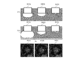
- An example of recovering the cytoplasm and cell membrane from cells in this embodiment is shown.
- An example of the present embodiment in which cells are attached to bubbles and detached is shown.
- An example of a schematic diagram showing a method for recovering cells in this embodiment is shown.
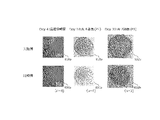
- An example of a passaged cell in this embodiment is shown.
- An example of a passaged cell in this embodiment is shown.
- An example of analyzing the recovered cells in this embodiment is shown.
- An example of a schematic diagram showing the retained cells in this embodiment is shown.
- An example of compressed cells in this embodiment is shown.
- the interface free energy decreases with the lapse of time in the bubble formed in the liquid containing a contaminant.
- FIG. 1A shows an example of the device configuration of the biological body operating device 100 in the present embodiment.
- the organism manipulation device 100 according to the present invention manipulates minute organisms such as cells by using the interface between a gas and a liquid.
- the organism manipulation device 100 can perform various operations on the organism, such as attaching the organism to the interface and then peeling off the organism adhered to the solid phase.
- the biological body operation device 100 includes a microscope unit 50, a camera 60, a camera 70, an operation unit 101, an output unit 160, an information processing device 170, and an input unit 180.
- the microscope unit 50 is a device for magnifying and observing or displaying the operation target 35 using a microscope.
- the operation target 35 is an organism.
- the organism may be an organic organism.
- the organism may be a cell.
- the cell may be an animal cell or a plant cell.
- the cell may be a living cell or a dead cell.
- the organism may be a minute organism other than a cell.
- the microscopic organism may be a microorganism, a fungus, an algae, a biological tissue, a spheroid, or the like.
- the organism may also contain intracellular organelles.
- the microscope unit 50 includes a light source 1 for observing a fluorescent image, a dichroic mirror 2, a light deflector 3, a relay lens 4, a dichroic mirror 5, an objective lens 6, a condenser lens 7, and a condenser lens 8. It includes a bandpass filter 9, a light source for observing a transmission image 10, a barrier filter 11, a projection lens 12, a barrier filter 13, a projection lens 14, a pinhole 15, a light source 16, and a light source 17.
- the fluorescent image observation light source 1 is a light source used when observing the fluorescent image of the operation target 35.
- the operation target 35 may or may not be fluorescently labeled with one or more types of fluorescent substances.
- the fluorescence image observation light source 1 irradiates the operation target 35 with light to be excited or reflected.
- the transmitted image observation light source 10 is a light source used when observing the transmitted image of the operation target 35.
- the light source 10 for observing a transmitted image shines light transmitted through the operation target 35.
- the light transmitted through the operation target 35 may pass through the outside of the nozzle or the inside of the nozzle.
- the microscope unit 50 may have a known configuration.
- the structure of the microscope unit 50 may have the structure described in Japanese Patent Application Laid-Open No. 7-13083 or Japanese Patent No. 3814869.
- the camera 60 captures a fluorescent image of the operation target 35 and generates an image.
- the image data generated by the camera 60 may be recorded inside the information processing apparatus 170 (for example, the recording unit 190 described later) and / or may be output to the output unit 160.
- the camera 60 may be a camera that captures a fluorescent image, but is not limited to this. In the following description, the camera 60 is a camera that captures a fluorescent image.
- the camera 70 captures a transmitted image of the operation target 35 and generates an image.
- the image data generated by the camera 70 may be recorded inside the information processing apparatus 170 (for example, the recording unit 190 described later) and / or may be output to the output unit 160.
- the camera 70 may be a camera that captures a transmitted image, but is not limited to this. In the following description, the camera 70 is a camera that captures a transmitted image.
- the camera 60 and the camera 70 have an image pickup sensor (not shown).
- the camera 60 and the camera 70 may be cooling cameras.
- a cooling camera is a camera that can suppress noise generated by heat by cooling an image sensor.
- the image pickup sensor may be a CMOS image sensor (Complementary Metal Oxide Semiconductor) or a CCD image sensor (Charge Coupled Device).
- the camera 60 and the camera 70 may be housed in a housing different from that of the microscope unit 50.
- the operation unit 101 operates the operation target 35 using the gas-liquid interface between the gas and the liquid.
- the operation unit 101 forms bubbles in the liquid to operate an organism (for example, a cell) in the liquid.
- the operation unit 101 includes a nozzle actuator 40, a sample actuator 41, a flow path imaging camera 42, a light source 45, a light source 46, a pressure generation unit 47, a sensor unit 48, a nozzle 49, and a flow path. It has all or at least a part of 51, a flow path exchange unit 53, a liquid storage unit 54, a sample lid 58, and a sample lid storage unit 59.
- the nozzle actuator 40 mounts the nozzle 49 via the pressure generating unit 47 and moves the nozzle 49. As will be described later, a flow path 51 is formed inside the nozzle 49, and a gas-liquid interface 255 such as air bubbles is formed at the tip or inside of the flow path 51.
- the nozzle actuator 40 may be capable of operating in any of the vertical, horizontal, and vertical directions. The nozzle actuator 40 may be operable only in the vertical direction. In this case, the vertical and horizontal movements of the nozzle actuator 40 may be operated by the stage of the microscope unit 50. The nozzle actuator 40 may be operable only in the vertical and horizontal directions. In this case, the vertical movement of the nozzle actuator 40 may be operated by the stage of the microscope unit 50. The nozzle actuator 40 may be fixed without operating.
- the vertical / horizontal and vertical movements of the nozzle actuator 40 may be operated by the stage of the microscope unit 50.
- the operation of the nozzle actuator 40 is controlled by the nozzle position control unit (not shown) of the volume control unit in the information processing device 170.
- the sample actuator 41 moves a stage (not shown) on which the container 25 is mounted.
- the sample actuator 41 may be capable of operating in any of the vertical, horizontal, and vertical directions.
- the stage may be equipped with a transparent container 25 for accommodating the operation target 35.
- the container 25 may be a culture container filled with a liquid.
- the sample actuator 41 may include, but is not limited to, one or more containers and / or tubes.
- the operation of the sample actuator 41 is controlled by a stage position control unit (not shown) of the volume control unit in the information processing device 170.
- the stage may be provided in the operation unit 101 or in the microscope unit 50.
- the flow path imaging camera 42 images the tip of the nozzle 49.
- the flow path image pickup camera 42 may take an image of bubbles formed at the tip of the nozzle 49.
- the captured image may be sent to the image processing unit in the information processing apparatus 170.
- the volume control unit 200 may instruct the nozzle actuator 40 and / or the sample actuator 41 to move the relative position between the nozzle 49 and the operation target 35.
- a camera 60 or a camera 70 may image the tip of the nozzle 49.
- the flow path imaging camera 42 may be a microscope attached camera provided in the microscope unit 50.
- the camera included in the microscope unit 50 may use a light source for observing a fluorescent image 1, a light source for observing a transmitted image 10, a light source 16, a light source 17, a light source 45, and a light source 46 as illumination.
- the light source 16 and the light source 17 may be, but are not limited to, ring illumination.
- the light source 45 and the light source 46 illuminate the nozzle 49 and / or the operation target 35.
- the light source 45 and the light source 46 may be, but are not limited to, ring illumination.
- the pressure generation unit 47 generates the pressure to be applied to the flow path 51.
- the pressure generating unit 47 is connected to one end of the flow path 51 that does not come into contact with the liquid, and supplies a preset gas to the one end.
- the pressure generating unit 47 may have an actuator for reciprocating the syringe pump and the plunger of the syringe pump. The actuator pushes the plunger of the syringe pump toward the flow path 51 to supply gas to the flow path 51, and the actuator pulls the plunger of the syringe pump from the flow path 51 side to supply gas from the flow path 51. You may inhale.
- the pressure generation unit 47 is controlled by the volume control unit in the information processing apparatus 170.
- the liquid in which the operation target 35 is immersed may be, but is not limited to, a complete medium, a basal medium, or a buffer solution.
- a complete medium is a medium containing maintenance and growth factors necessary for cell maintenance and growth.
- the basal medium is a medium containing a small part of protein, amino acid or salt.
- the buffer is a liquid that maintains a pH and osmotic pressure suitable for cell survival. Known liquids, complete media, basal media, and buffers can be used.
- the gas may be air.
- the gas may contain water.
- the sensor unit 48 has one or more sensors, and detects the state of the nozzle 49 and the liquid and gas in the nozzle 49.
- the sensor unit 48 may detect the position, velocity and acceleration of the nozzle 49.
- the sensor unit 48 may detect the position of the nozzle actuator 40, the pressure generated in the pressure generation unit 47, the position of the plunger of the syringe pump in the pressure generation unit 47, and the like.
- the sensor unit 48 may detect the environmental temperature and the temperature of the liquid in the container 25.
- the sensor unit 48 may detect the humidity of the environment. Further, the sensor unit 48 may detect the pH of the liquid in the container 25.
- the sensor unit 48 may detect the temperature and humidity of the gas in the nozzle 49.
- the sensor unit 48 sends this information to the information processing device 170 (for example, the volume control unit 200 described later).
- the information processing device 170 for example, the volume control unit 200 described later.
- the sensor used in the sensor unit 48 a known sensor can be used.
- the sensor unit 48 may have a different housing from the pressure generating unit 47, or may be housed inside the pressure generating unit 47.
- the nozzle 49 is a device provided with a flow path 51, which will be described later.
- the nozzle 49 may have a rod shape or a flat plate shape.
- the flow path 51 introduces gas from the end 254 arranged in the liquid through which the liquid and gas to be sucked (intake) or discharged (supplied) pass and the operation target 35 is immersed.
- the flow path 51 is provided inside the nozzle 49 so as to penetrate the longitudinal direction of the nozzle 49.
- a pressure generating portion 47 is connected to the other end side of the flow path 51.
- the flow path exchange unit 53 is a device for storing and disposing of the nozzle 49.
- the flow path switching unit 53 removes the nozzle 49 mounted on the nozzle actuator 40 and disposes of it in the nozzle disposal unit (not shown) of the flow path exchange unit 53, and disposes of the nozzle 49 in the nozzle disposal unit (not shown).
- the nozzle 49 stored in the nozzle storage unit (not shown) of 53 may be attached to the nozzle actuator 40 instead.
- the flow path exchange unit 53 may be omitted, in which case the nozzle 49 may be exchanged by the operator.
- the liquid storage unit 54 is a device for storing the liquid supplied to the container 25 and collecting and disposing of the liquid from the container 25.
- the liquid storage unit 54 collects the liquid contained in the container 25 from the container 25 and disposes of it in the liquid disposal unit (not shown) of the liquid storage unit 54, and the liquid in the liquid storage unit 54.
- the liquid stored in the storage unit (not shown) may be replenished in the container 25.
- the liquids may be exchanged between liquids of the same type. Liquids may be exchanged between different types of liquids.
- the liquid storage unit 54 may be omitted, in which case the liquid may be replaced by the operator's hand.
- the sample lid 58 is a lid attached to the container 25.
- the sample lid 58 may be attached to the container 25 or may be stored in the sample lid storage unit 59. If necessary, the sample lid 58 is taken out from the sample lid storage unit 59 and attached to the container 25 by an actuator for the sample lid (not shown), and is removed from the container 25 to the sample lid storage unit 59. Storage may be done. In this case, the operation of the sample lid actuator may be controlled by the sample lid control unit (not shown) of the volume control unit 200 in the information processing apparatus 170.
- the sample lid 58 and the sample lid storage unit 59 may be omitted, in which case the sample lid 58 may be attached to and removed from the container 25 by the operator.
- the liquid storage unit 54 may store a liquid that can change the difference in interfacial free energy (E1-E2) with respect to the liquid that fills the container 25, and the details will be described later.
- Liquid replenishment and / or disposal may be performed via a liquid flow path (not shown) connecting the container 25 and the liquid reservoir 54.
- the liquid flow path may be one that connects the container 25 and the liquid storage unit so that the liquid can flow.
- the liquid flow path may be one that connects the container 25 and the liquid disposal unit so that the liquid can flow.
- the liquid flow path may be a pipette.
- the liquids may be exchanged between liquids of the same type. Liquids may be exchanged between different types of liquids.
- the liquid storage unit 54 may be omitted, in which case the liquid may be replaced by the operator's hand.
- the output unit 160 outputs the processing result of the information processing device 170.
- the output unit 160 outputs an image that has been image-processed by the inside of the information processing device 170 (for example, the image processing unit 300 described later).
- the output unit 160 is a monitor connected to the information processing device 170.
- the information processing device 170 exchanges commands and data with the microscope unit 50, the camera 60, the camera 70, the operation unit 101, the output unit 160, and the input unit 180.
- the information processing apparatus 170 is connected to the microscope unit 50 and the operation unit 101, and controls the microscope unit 50 and the operation unit 101.
- the information processing apparatus 170 switches the combination with the type of the objective lens 6 arranged in the optical path of the microscope unit 50 and / or the type of the filter cube of the fluorescence filter.
- the transmission image observation and the fluorescence image observation differ in both the type of the filter cube arranged in the optical path and the type of the objective lens 6.
- the two types of fluorescence image observation differ only in the type of the filter cube arranged in the optical path.
- the light sources used for the transmission image observation and the fluorescence image observation (the transmission image observation light source 10 and the fluorescence image observation light source 1 are different, respectively).
- the inside of the information processing apparatus 170 depends on whether at least one or a plurality of transmission image observations and one type or two or more types of fluorescence image observations are performed. , Filter block, objective lens 6, and one or more light sources may be switched.
- the information processing apparatus 170 When observing a fluorescent image, the information processing apparatus 170 turns on the light source 1 for observing a fluorescent image and turns off the light source 10 for observing a transmitted image in order to enable the optical path of the light source 1 for observing a fluorescent image.
- the light emitted from the light source for observing the fluorescent image illuminates the operation target 35 via the dichroic mirror 2, the light deflector 3, the relay lens 4, the dichroic mirror 5, and the objective lens 6.
- the fluorescent substance of the operation target 35 is excited and emits fluorescence.
- the fluorescence emitted from the operation target 35 is the objective lens 6, the dichroic mirror 5, the relay lens 4, the optical deflector 3, the dichroic mirror 2, the barrier filter 13, the projection lens 14, and the pinhole 15 (the microscope unit 50 is confocal). (In the case of a microscope), it reaches the light receiving surface of the camera 60. At this time, a fluorescent image of the operation target 35 is formed on the camera 60. Even when the operation target 35 is not fluorescently labeled, the light emitted from the fluorescent image observation light source 1 hits the operation target 35, and the operation target 35 can be observed using the light reflected from the operation target 35. ..
- the information processing apparatus 170 When observing a transmitted image, the information processing apparatus 170 turns on the transmitted image observing light source 10 and turns off the fluorescent image observing light source 1 in order to enable the optical path of the transmitted image observing light source 10.
- the light emitted from the transmitted image observing light source 10 illuminates the operation target 35 via the bandpass filter 9, the condenser lens 8, and the condenser lens 7.
- the light transmitted through the operation target 35 reaches the light receiving surface of the camera 70 through the objective lens 6, the dichroic mirror 5, the barrier filter 11, and the projection lens 12. At this time, a transmitted image of the operation target 35 is formed on the camera 70. If the end portion of the nozzle 49 is difficult to see in fluorescence observation, transmission image observation may also be performed.
- the information processing apparatus 170 controls the relative positions of the nozzle 49 and the stage of the operation unit 101. Further, in the information processing apparatus 170, in addition to the control of the microscope unit 50 and the operation unit 101, the operation target 35 and / or the flow path image pickup camera 42 of the operation unit 101 imaged by the camera 60 and / or the camera 70. May receive an image captured by the camera and perform image processing such as generating one composite image from a plurality of images. The information processing apparatus 170 may control other operations of the organism operating apparatus 100, process data, and the like as necessary. The configuration of the information processing apparatus 170 will be described later.
- the input unit 180 inputs instructions and data from the operator to the information processing device 170. For example, the input unit 180 inputs an instruction from the operator regarding the selection of the operation application for the operation target 35. Further, the input unit 180 inputs the operating amount of the nozzle actuator 40 and / or the sample actuator 41 from the operator to the information processing apparatus 170.
- the input unit 180 is a keyboard or mouse connected to the organism operating device 100.
- FIG. 1B shows another example of the device configuration of the biological body operating device 100 in the present embodiment.
- FIG. 1B shows a biological body manipulation device 100 when the microscope unit 50 is a phase-contrast microscope or a differential interference microscope.
- the microscope unit 50 includes an objective lens 6 (which may include a phase plate), a condenser lens 7, a condenser lens 8, a bandpass filter 9, and a transmission image observation.
- a light source 10, a barrier filter 11, a projection lens 12, a light source 16, a light source 17, and a ring aperture 39 may be provided.
- the microscope unit 50 When the microscope unit 50 is a differential interference microscope, the microscope unit 50 includes an objective lens 6, a condenser lens 7, a condenser lens 8, a bandpass filter 9, a transmission image observation light source 10, and a barrier filter 11.
- a projection lens 12, a light source 16, a light source 17, a normal ski prism 31, an analyzer (plate plate) 32, a polarizer (plate plate) 37, and a normal ski prism 38 may be provided.
- the microscope unit 50 may have a configuration other than those described above.
- the phase-contrast microscope may be provided with a normal ski prism 31 or the like, or the differential interference microscope may be provided with a ring diaphragm 39 or the like.
- the description of FIG. 1A may be applied to the configuration of the organism manipulation device 100 other than the microscope unit 50.
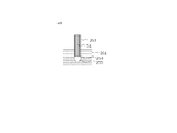
- the nozzle 49 comprises a tubular portion 253 having a flow path 51.
- the tubular portion 253 may have a hollow cylindrical shape.
- the shape of the cross section of the tubular portion 253 orthogonal to the axial direction is a circle.
- the flow path 51 may be connected to the pump 251 (for example, the syringe pump of the pressure generating unit 47) on one end side.
- the pump 251 receives an instruction from the information processing device 170 (for example, the volume control unit 200 described later) to supply air to the flow path 51 or adjust the amount of gas taken in from the flow path 51 to control the amount of air bubbles. Adjust pressure and / or volume.
- the gas-liquid interface 255 is formed at the end 254 of the flow path 51, but both the gas and the liquid are present inside the flow path 51.
- a gas-liquid interface 255 may be formed at the interface between the two inside the flow path 51.
- the gas-liquid interface 255 When the gas-liquid interface 255 comes into contact with an organism adhering to a solid phase such as the inner bottom surface of the container 25 in the liquid 261, the gas-liquid interface 255 exerts a force on the organism by moving the gas-liquid interface 255.
- the organism can be detached from the solid phase and attached to the gas-liquid interface 255.
- the movement of the gas-liquid interface 255 may be performed by moving the nozzle 49 on which the bubbles are formed by the nozzle actuator 40, by moving the liquid, or by changing the volume of the bubbles. You may go.
- the solid phase may be a surface on which adherent cells can be adhered and cultured.
- the solid phase is glass; a resin such as polystyrene; a metal; a surface coated with one or more extracellular matrix components selected from collagen, fibronectin, laminin, polylysine, etc .; various polymers (eg, hydrophilic).
- the surface may be coated with (a polymer capable of controlling adsorption to cells), but the surface is not limited thereto.
- the gas-liquid interface 255 is formed by the interface between the gas and the liquid, but the present invention is not limited to this, and the gas-liquid interface 255 may be changed depending on the phase or substance in contact with the interface.
- the gas-liquid interface 255 comes into contact with an organism adhering to a solid phase such as the inner bottom surface of the container 25 in the liquid 261, the gas-liquid interface 255 is moved after the organism is attached to the gas-liquid interface 255. This may separate the organism from the solid phase, or the gas-liquid interface 255 may press the organism without attaching the organism to the gas-liquid interface 255. Details of the method for exfoliating the organism from the solid phase will be described later.
- the opening area of the flow path 51 at the end 254 is not particularly limited as long as the size is such that the organism can be manipulated.
- the opening area may be larger than the adhesive area per organism.
- the shape of the end portion 254 is not particularly limited.
- the inner diameter of the flow path 51 may be the same over the entire length of the tubular portion 253.
- the gas-liquid interface 255 may be formed inside the flow path 51.
- the flow path 51 may be one in which the pump 251 takes in the gas in the bubbles to which the organism is attached, so that the gas-liquid interface 225 is taken into the flow path 51 and the organism is further recovered.
- the nozzle 49 may further include another flow path for collecting the organism, in addition to the flow path 51.
- FIGS. 3A and 3B are examples of schematic views showing the structure of the nozzle 49 in another embodiment.
- the case where the flow path forming the bubble and the flow path for collecting the organism are the same is shown, but in the examples of FIGS. 3A and 3B, the flow path forming the bubble and the organism are shown.
- the case where the flow path for collecting the waste is different is shown.
- the tubular portion 253 of the nozzle 49 has a double structure of an outer cylinder 253a and an inner cylinder 253b. Between the outer cylinder 253a and the inner cylinder 253b is a first flow path 51a through which gas flows, and inside the inner cylinder 253b is a second flow path 51b.
- the first flow path 51a may be a gas supply flow path
- the second flow path 51b may be a gas recovery flow path.
- first flow path 51a and the second flow path 51b of the nozzle 49 may be connected to the first pump 251a and the second pump 251b at one end side, respectively.
- the pressure generating unit 47 may have a first pump 251a and a second pump 251b as syringe pumps, each of which may be controlled by a separate actuator.
- the actuators that receive instructions from the volume control unit, which will be described later, adjust the amount of gas supplied to or taken in from the first flow path 51a and the second flow path 51b, respectively. By doing so, the pressure and / or volume of the bubbles is adjusted.
- the shape of the cross section of the tubular portion 253 orthogonal to the axial direction is a donut shape in the first flow path 51a and a circle in the second flow path 51b.
- the first pump 251a is gas in the first flow path 51a.
- bubbles can be formed at the end portion 254.
- a gas-liquid interface 255 is formed at the boundary between the gas and the liquid 261 of the bubbles.
- the second pump 251b may take in the gas-liquid interface 225 into the flow path 51 by sucking bubbles to which the organism adheres through the second flow path 51b, and collect the organism.
- the first pump 251a supplies gas to the first flow path 51a to form bubbles
- the second pump 251b sucks gas through the second flow path 51b to form an organism.
- the second pump 251b supplies gas to the second flow path 51b to form bubbles
- the first pump 251a sucks gas through the first flow path 51a to form an organism. May be collected.
- the first pump 251a and the second pump 251b may be the same syringe pump provided in the pressure generation unit 47. Either one of the first pump 251a and the second pump 251b may be omitted.
- bubbles can be formed in one flow path to attach the organism to the gas-liquid interface 255, and the organism attached in the other channel can be recovered at the same time. Therefore, it has the effect of shortening the time for collecting cells.
- the shape of the cross section of the tubular portion 253 orthogonal to the axial direction is a donut shape in the first flow path 51a and a circle in the second flow path 51b.
- the shape of the cross section is not limited to the donut shape or the circle, and if there are two channels, the organisms can be attached and recovered at the same time.
- FIG. 4 is a schematic diagram showing an example of a method for recovering the operation target 35 in the present embodiment.
- the operation target 35 is cultured in the solid phase on the inner bottom surface of the container 25.
- the operation target 35 may be cultured in the liquid 261.
- the operation target 35 is an adherent cell.
- the liquid may be a complete medium.
- the pump 251 supplies gas to the flow path 51 of the nozzle 49 and forms bubbles 256 at the end 254 of the nozzle 49.
- the pump 251 regulates the gas supply and intake to maintain the formed bubbles 256. This makes it possible to more easily operate the operation target 35 by the bubble 256.
- the nozzle actuator 40 moves the nozzle 49 along the surface of the solid phase while keeping the bubble 256 in contact with the operation target 35.
- FIG. 4 describes how the nozzle actuator 40 moves the nozzle 49 from left to right, but the direction in which the nozzle 49 is moved is not limited as long as it is parallel to the surface of the solid phase.
- the volume control unit 200 controls the pump 251 to adjust the pressure and / or volume of the gas supplied or taken in, and changes the size of the bubble 256 to peel off the operation target 35 within a desired range. can do. Instead of moving the nozzle 49 along the surface of the solid phase, the stage may be moved.
- the operation target 35 adhering to the gas-liquid interface 255 may be recovered by the pump 251 sucking the gas in the flow path 51.
- the bubble 256 formed in the nozzle 49 can be used to selectively peel off the operation target 35 from the solid phase and recover it.
- the adhesion of the adherent cell may be relaxed in advance before the method of FIG. 4 is carried out.
- the relaxation of adhesion of adherent cells can be performed by using a known method, as will be described later.
- FIG. 4 describes an example in which the gas-liquid interface 255 is moved by moving the nozzle 49 to exfoliate and collect cells, but the movement of the gas-liquid interface 255 is not limited to the above example.
- the volume of the bubble 256 may be increased after the bubble 256 is brought into contact with the operation target 35.
- the contact surface between the bubble 256 and the solid phase is widened, and the operation target can be selectively separated from the solid phase and recovered.
- the nozzle actuator 40 may move the nozzle 49 so as to approach the solid phase.
- the contact surface between the bubble 256 and the solid phase expands, and the operation target can be selectively separated from the solid phase and recovered.
- FIG. 5 shows an example of a specific configuration of the information processing apparatus 170 in the present embodiment.
- the information processing apparatus 170 includes an image pickup control unit 171, a recording unit 190, a flow path control unit 250, an image processing unit 300, and an energy control unit 500.
- the image pickup control unit 171 includes a fluorescent image observation light source 1, an objective lens 6, a fluorescent filter, a transmitted image observation light source 10, a flow path image pickup camera 42, a light source 45, a light source 46, and a camera 60 described in FIGS. 1A and 1B. , And the camera 70, and the like.
- the imaging control unit 171 switches cameras, switches the type of the objective lens 6 in the microscope unit 50, and uses a light source according to the input imaging conditions. Of the switching, switching of the type of fluorescence filter, the position of the stage, and the height of the objective lens 6, necessary adjustments are made for each imaging.
- one or more of the flow path image pickup camera 42, the camera 60, and the camera 70 captures the operation target 35 or the nozzle 49 and operates. Generate an image of the object 35 or the nozzle 49.
- One or more cameras send the generated image data to the image processing unit 300. Further, the generated image data may be recorded in the recording unit 190 and / or output to the output unit 160.
- the recording unit 190 may be, but is not limited to, a memory, an internal hard disk drive, or an external recording medium.
- the information processing device 170 has a central processing unit (CPU), and the CPU realizes the information processing device 170 and the like by executing a computer program recorded in the recording unit 190.
- CPU central processing unit
- the flow path control unit 250 controls the storage, mounting and disposal of the nozzle 49.
- the flow path control unit 250 receives from the input unit 180 an operation instruction regarding mounting and disposal of the nozzle 49 from the operator.
- the flow path control unit 250 takes out the nozzle 49 from the flow path storage unit of the flow path exchange unit 53 according to the received instruction, mounts the nozzle 49 on the nozzle actuator 40, or mounts the nozzle 49 on the nozzle actuator 40.
- An instruction is sent to the flow path exchange unit 53 to remove the nozzle 49 and dispose of it in the flow path disposal unit of the flow path exchange unit 53.
- the image processing unit 300 receives the images captured by the flow path imaging camera 42, the camera 60, and the camera 70 from these cameras.
- the image processing unit 300 may combine a plurality of the received images into one composite image.
- the image processing unit 300 may generate a composite image by synthesizing the fluorescence image captured by the camera 60 and the transmission image captured by the camera 70.
- the image processing unit 300 may record the images received from these cameras and / or the composite image in the recording unit 190 and / or output them to the output unit 160.
- the energy control unit 500 controls the environment of the operation unit 101 such as the gas supplied to the flow path 51, the liquid filled in the container 25, the relative positional relationship between the operation target 35 and the nozzle 49, and the temperature and humidity. ..
- the energy control unit 500 controls the difference (E1-E2) obtained by subtracting the interface free energy E2 at the interface between the gas and the liquid from the interface free energy E1 at the interface between the gas and the organism.
- the value of the difference (E1-E2) may be a positive value, 0, or a negative value. The smaller the value of the difference (E1-E2), the more the organism adheres to the bubble.
- the value of the interface free energy E1 is constant, there is little room for control by the energy control unit 500.
- the energy control unit 500 may include all or a part of the volume control unit 200, the liquid control unit 260, the temperature control unit 520, and the humidity control unit 530.
- the volume control unit 200 controls the pressure and / or volume of the gas supplied or taken into the flow path 51, the movement of the nozzle 49, and the movement of the stage.
- the volume control unit 200 controls the actuator of the pressure generation unit 47 in the operation unit 101, and is formed in the flow path 51 by supplying gas from the syringe pump connected to the flow path 51 or sucking gas into the syringe pump. Control the pressure and / or volume of the resulting bubbles.
- the volume control unit 200 controls the actuator to push or pull the syringe pump at a predetermined pressure or distance.
- the volume control unit 200 may control the gas introduction speed (air supply speed) and / or the suction speed (intake speed). Specifically, the volume control unit 200 controls the actuator of the pressure generation unit 47 to adjust the speed at which the syringe pump is moved or the pressure at which the syringe pump is pushed to form a bubble, and / or operate the volume control unit 200.
- the speed at which the target 35 is collected may be controlled. For example, by increasing the speed at which the syringe pump is pushed or the pressure at which the syringe pump is pushed is increased to increase the speed at which gas is sucked into the syringe pump, the speed at which the operation target 35 is collected is increased, and the operation target 35 is collected. Can be made easier.
- volume control unit 200 may receive information on the gas introduction speed and the suction speed from the pressure generation unit 47 or the sensor unit 48.
- the volume control unit 200 may calculate the pressure and volume of the bubbles formed in the flow path 51 from these information.
- the volume control unit 200 may include all or a part of the nozzle position control unit, the stage position control unit, the air supply control unit, and the intake air control unit.
- the nozzle position control unit controls the nozzle actuator 40, and controls the operation of the nozzle 49, the air flow in the bubbles accompanying the operation of the nozzle 49, and the movement of the gas-liquid interface 255 accompanying the operation of the nozzle 49. Further, the nozzle position control unit receives the position information of the nozzle 49 from the sensor unit 48 or the nozzle actuator 40.
- the stage position control unit controls the sample actuator 41 and operates the stage equipped with the container 25 accommodating the operation target 35, the air flow in the bubbles accompanying the operation of the stage, and the gas-liquid interface 255 accompanying the operation of the stage. Control the movement of. Further, the stage position control unit receives the position information of the stage and the operation target 35 from the sensor unit 48 or the sample actuator 41.
- the air supply control unit when the nozzle 49 includes a gas supply flow path for supplying (supplying) gas and a gas recovery flow path for recovering (intake) gas, the air supply control unit is used.
- the first pump 251a connected to the gas supply flow path may be controlled, whereby the volume of gas supplied to the gas supply flow path may be controlled.
- the volume control unit 200 or the air supply control unit receives information on the amount of gas supplied to the gas supply flow path from the nozzle actuator 40, the pressure generation unit 47, or the sensor unit 48.
- the intake control unit is a gas.
- the second pump 251b connected to the recovery flow path may be controlled, whereby the amount (volume) of the gas taken in from the gas recovery flow path may be controlled.
- the volume control unit 200 or the intake control unit receives information on the amount of gas taken in from the gas recovery flow path from the nozzle actuator 40, the pressure generation unit 47, or the sensor unit 48.
- the liquid control unit 260 controls the storage, replenishment and disposal of liquid.
- the liquid control unit 260 receives an operation instruction regarding replenishment and disposal of the liquid from the operator from the input unit 180.
- the liquid control unit 260 replenishes the container 25 with the liquid stored in the liquid storage unit of the liquid storage unit 54, or collects the liquid contained in the container 25 from the container 25 and liquids according to the received instruction.
- An instruction is sent to the liquid storage unit 54 to dispose of it in the liquid disposal unit of the storage unit 54.
- the liquid control unit 260 discards all or at least a part of the liquid contained in the container 25, and replenishes the container 25 with the liquid stored in the liquid storage unit of the liquid storage unit 54. Then, an instruction may be sent to the liquid storage unit 54 to replace all or at least a part of the liquid contained in the container 25. Further, the liquid control unit 260 replenishes the container 25 with the liquid stored in the liquid storage unit of the liquid storage unit 54 without discarding the liquid stored in the container 25, thereby charging the container 25 with the liquid. You may send an instruction to the liquid storage unit 54 to add. The replacement or addition of the liquid may be performed via a liquid flow path connecting the liquid storage unit and the container 25.
- the temperature control unit 520 controls the temperature of the liquid.
- the temperature control unit 520 may control the temperature of the liquid contained in the container 25.
- the temperature control unit 520 may control the temperature of the liquid stored in the liquid storage unit of the liquid storage unit 54.
- the temperature control unit 520 may be connected to a temperature control device such as a heater or a cooler connected to the liquid storage unit 54 and / or the container 25.
- the temperature control device may be an electric heater or a Pelche type cooler.
- the temperature control unit 520 may control the temperature control device so that the temperature control device adjusts the liquid to a preset temperature.
- the temperature control unit 520 may control the value of the interface free energy at the gas-liquid interface 255 by adjusting the temperature of the liquid. The details of the mechanism by which the value of the interface free energy at the gas-liquid interface 255 is controlled by adjusting the temperature of the liquid will be described later.
- the humidity control unit 530 controls the humidity of the gas.
- the humidity control unit 530 may control the humidity of the gas supplied from the syringe pump.
- the humidity control unit 530 may be connected to a humidifier connected to the pressure generation unit 47.
- the humidity control unit 530 may control the humidifier so that the humidifier adjusts the gas to a preset humidity.
- the humidity control unit 530 may control the value of the interface free energy at the gas-liquid interface 255 by adjusting the humidity of the gas. The details of the mechanism by which the value of the interface free energy at the gas-liquid interface 255 is controlled by adjusting the humidity of the gas will be described later.
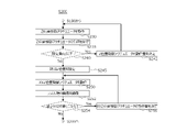
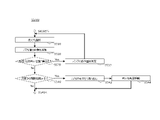
- FIG. 6 is an example of the flow of the method of manipulating an organism in the present embodiment.
- the organism that is the operation target 35 of the present embodiment can be operated by performing the processing of S100 to S680 of FIG.
- the processes of S100 to S680 will be described in order, but at least a part of these processes may be executed in parallel, and each step is not deviated from the gist of the present invention. It may be executed by exchanging.
- the sample actuator 41 accepts an organism to be operated 35.
- the sample actuator 41 mounts a container 25 containing a liquid and an operation target 35 on the stage.
- the lid of the container 25 may be removed in order to operate the operation target 35.
- the lid may be replaced by an actuator that replaces the lid, or may be replaced by the operator's hand.
- the information processing apparatus 170 advances the process to S120.
- the camera 60 or the camera 70 captures a wide range of observation fields including the operation target 35 and generates an image.
- the image pickup control unit 171 sets the observation method to low-magnification transmission image imaging, and sends an instruction to the camera 70 to image the observation field.
- the imaging control unit 171 may set the observation method to fluorescence image imaging and send an instruction to the camera 60 to image the observation field.
- the image pickup control unit 171 may receive input of image pickup conditions from the operator via the input unit 180.
- the camera 60 or the camera 70 images the observation field.
- the image processing unit 300 may record the captured image in the recording unit 190 and / or output it to the output unit 160. After the camera 60 or the camera 70 images the observation field, the image pickup control unit 171 advances the process to S140.
- the information processing apparatus 170 receives input regarding the operation target 35 and the type of operation from the operator via the input unit 180.
- the operation target 35 may be a single cell, a population (colony) of cells, a cytoplasm and / or a cell membrane of a cell, or a spheroid, but is not limited thereto. ..
- the type of operation may be the collection of the operation target 35, the removal of the operation target 35, the holding of the operation target 35, or the compression of the operation target 35. Not limited to.
- the information processing apparatus 170 receives an input regarding the difference (E1-E2) obtained by subtracting the interface free energy E2 at the interface between the gas and the liquid from the interface free energy E1 at the interface between the gas and the organism, and then the operation target. You may receive inputs regarding 35 and the type of operation. Further, the information processing apparatus 170 may output an operation candidate for controlling the difference (E1-E2) when receiving the input regarding the operation target 35 and the operation type.
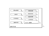
- FIG. 7A is an example of a GUI (Graphical User Interface) image displayed on the output unit 160 and captured by the camera 60 or the camera 70 in the observation field.
- the cells aaa, bbb, and ccc to be operated are designated as the operation target 35 via the input unit 180.
- the organism to be operated is arbitrarily designated via the input unit 180.
- the removal area and / or the protection area may be provided in the observation field so that the removal area and / or the protection area is selected in the GUI image. By providing the removal region, the risk of recovery of cells other than the recovery cells can be reduced. In addition, by providing the protected area, it is possible to reduce the risk of accidentally removing the recovered cells when removing the cells in the removed area.
- FIG. 7B is a GUI image in which the collection destination and the destination of the cells aaa, bbb, and ccc to be operated 35 displayed on the output unit 160 are designated as A1, A2, and A3 of the 12-hole plate, respectively.
- the movement destination is arbitrarily designated via the input unit 180.
- the destination may be the same plate, a different plate, a petri dish, a microtest tube, a PCR tube, or a conical tube. There may be.
- FIG. 7C shows the ID number of the cell to be operated, the xy coordinates of the operation target 35 on the sample actuator 41, the size of the operation target 35, and the destination of the operation target 35 displayed on the output unit 160.
- This is an example of a GUI image that displays a table listing the above.
- the image processing unit 300 may output the table to the output unit 160 by designating the operation target 35, the moving destination, and the like via the input unit 180.
- FIG. 7D is an example of a GUI screen displayed on the output unit 160 for selecting the operation type of the operation target 35.
- the input unit 180 receives an instruction from the operator as to what kind of operation the operation target 35 wants to perform, and inputs the input to the information processing apparatus 170.
- manipulation of cells may be passage, retention or migration of cells, but is not limited to these.
- the operation on the cell may be, but is not limited to, compressing the cell and observing the deep part of the cell.
- FIG. 7D shows an example in which the type of operation is selected by a radio button, but the selection method is not limited to the radio button.
- FIG. 7E is another example of the GUI screen displayed on the output unit 160 for selecting the operation type of the operation target 35.
- the type of operation on the cell may be selected by the pull-down menu.
- the pull-down menu and the radio button may be used together to select the operation type.
- the input unit 180 may send the instruction input from the operator to the information processing apparatus 170 based on the screens shown in FIGS. 7A to 7E. After receiving the instruction from the information processing apparatus 170, the image pickup control unit 171 advances the processing to S160.
- an additional step of relaxing the adhesion of the adherent cell may be performed in advance.
- the information processing apparatus 170 may receive an input as to whether or not to perform a process of relaxing the adhesion.
- the adhesion of adherent cells can be relaxed by using a known method.
- the relaxation of adhesion of adherent cells may be performed by removing the liquid (for example, medium), washing with a buffer solution, and then treating the adherent cells with an adhesion relaxation solution.
- the adhesion relaxation solution may be a proteolytic enzyme solution, a solution containing no metal ions, or a chelating agent solution.
- the adhesion relaxation solution is a trypsin-EDTA solution.
- the relaxation of the adhesion of the adherent cells may be performed by the liquid control unit 260 or may be performed by the operator.
- the process may proceed to S160.
- the step is performed by the operator, the step of accepting the sample of S100 may be started again.
- the adhesive force may be weakened by using a base material that relaxes the adhesion.
- the substrate that relaxes the adhesion may be one that relaxes the adhesion in response to temperature or light irradiation.
- the information processing apparatus 170 receives an input regarding the liquid replacement or addition process from the operator via the input unit 180. For example, when it is desired to adjust the adhesive force between the organism to be operated 35 and the bubble, the information processing apparatus 170 may receive an input to perform a liquid replacement or addition process. When the information processing apparatus 170 is instructed to perform the liquid replacement or addition processing, the information processing apparatus 170 may proceed to the processing to S600. When the information processing apparatus 170 is instructed not to perform the liquid replacement or addition processing, the information processing apparatus 170 may proceed to the processing to S180.
- the liquid control unit 260 replaces the liquid in the container 25 in which the operation target 35 is housed, or adds another liquid to the liquid in the container 25.
- the step of performing the liquid replacement or addition treatment includes the steps of S610 to S630 as shown in FIG.
- the information processing apparatus 170 receives an input from the operator regarding whether or not to remove the liquid via the input unit 180.
- the process proceeds to S615.
- the process proceeds to S620.
- the liquid control unit 260 controls the liquid storage unit 54 to remove the liquid.
- the liquid control unit 260 sends an instruction to the liquid storage unit 54 to collect a preset amount of the liquid contained in the container 25 from the container 25 and dispose of it in the liquid disposal unit of the liquid storage unit 54.
- the liquid storage unit 54 may collect and dispose of the entire amount of the liquid. Instead, the liquid storage unit 54 may collect and dispose of a part (for example, half of the amount) of the liquid.
- the liquid control unit 260 advances the process to S620.
- the liquid control unit 260 sends an instruction to the liquid storage unit 54 to add the adhesive force adjusting reagent to the container 25.
- the adhesive force adjusting reagent is a reagent that adjusts the adhesive force between an organism and bubbles.
- the adhesive force adjusting reagent may be one that changes the concentration of the inorganic salt in the liquid and / or the concentration of the amphipathic substance.
- the adhesion adjusting reagent may be a buffer solution containing or not containing at least one of calcium ion or magnesium ion, may be a basal medium, may be a complete medium, or may be a chelating agent. May be.
- the liquid storage unit 54 replenishes the container 25 with the adhesive force adjusting reagent stored in the liquid storage unit of the liquid storage unit 54.
- an example of replenishing the adhesive force adjusting reagent to the container 25 has been described, but instead of adding the adhesive force adjusting reagent to the container 25, an inorganic salt or an amphipathic substance contained in the liquid is filtered.
- the adhesive force between the organism and the air bubbles may be adjusted by attaching the reagent to the substance and removing it.
- the information processing apparatus 170 receives an instruction from the operator via the input unit 180 regarding whether or not to repeat the above series of operations.
- the information processing device 170 advances the process to S610, and the liquid control unit 260 sends an instruction to the liquid storage unit 54 to remove the liquid in the container 25. ..
- the information processing apparatus 170 advances the process to S180.
- the steps and sub-steps of S600 may be performed by the operator, and in this case, the sample reception step of S100 may be started again.
- the nozzle actuator 40 is equipped with the nozzle 49.
- the information processing apparatus 170 receives an instruction from the operator via the input unit 180 to mount the nozzle 49 on the nozzle actuator 40.
- the flow path control unit 250 takes out the nozzle 49 from the flow path storage unit of the flow path exchange unit 53 according to the instruction, and sends an instruction to the flow path exchange unit 53 to mount the nozzle 49 on the nozzle actuator 40.
- a suitable nozzle 49 may be selected according to the size of the operation target 35, the type of operation, and the like.
- the selection of the nozzle 49 may be specified by the operator via the input unit 180, or may be automatically specified by the flow path control unit 250.
- the flow path control unit 250 advances the process to S200. If the nozzle 49 is not required to be mounted on the nozzle actuator 40, such as when the nozzle 49 is pre-mounted on the nozzle actuator 40 or when the nozzle actuator 40 and the nozzle 49 are integrally formed. The step of S180 may be omitted.
- the nozzle actuator 40 moves the relative position between the nozzle 49 and the operation target 35.
- the volume control unit 200 sends an instruction to the nozzle actuator 40 to move the relative position between the nozzle 49 and the operation target 35.
- the volume control unit 200 sends an instruction to move the nozzle actuator 40 so that the nozzle 49 and the operation target 35 are relatively close to each other so that bubbles can be formed in the vicinity of the operation target 35. It's okay.
- the step of moving the relative position includes the step of S210 to S225 as shown in FIG. 9A, the step of S230 to S256 as shown in FIG. 9B, or as shown in FIG. 9C. Includes steps S260 to S282.
- FIG. 9A is an example of a flow for moving the relative position between the nozzle 49 and the operation target 35 based on the image obtained by capturing the position of the end portion 254 of the nozzle 49.
- the volume control unit 200 sends an instruction to operate the nozzle 49 to a preset position to the nozzle actuator 40.
- the nozzle actuator 40 may be an actuator that controls the xyz position.
- the z position may be a position in the vertical direction (also referred to as a direction along gravity, a vertical direction, or a z direction)
- the x position may be an arbitrary x direction (also referred to as a vertical direction) perpendicular to the z direction.
- the y position may be a position in the y direction (also referred to as a lateral direction) perpendicular to the x direction and the z direction.
- the position of the nozzle 49 is such that the camera 60 and / or the camera 70 is first focused on the bottom surface of the container 25, then the camera 60 and / or the camera 70 is moved upward by an arbitrary distance, and then the nozzle actuator 40 is used.
- the z position may be set by aligning the tip of the nozzle 49 with the focus of the camera 60 and / or the camera 70. For example, any distance may be less than or equal to the radius of the bubble formed at the end 254 of the nozzle 49.
- the distance between the tip of the nozzle 49 and the bottom surface of the container 25 is less than or equal to the radius of the bubbles to be formed, the bubbles come into contact with the bottom surface, so that the organism located on the bottom surface can be operated using the interface of the bubbles. can.
- the xy position of the nozzle 49 can be set by using the nozzle actuator 40 or the sample actuator 41 based on the image obtained by capturing the operation target 35 using the camera 60 and / or the camera 70.
- the position of the nozzle 49 may be set by using the flow path imaging camera 42 instead of the camera 60 and / or the camera 70, or in combination with the camera 60 and / or the camera 70.
- the z position of the nozzle 49 may be adjusted by using the flow path imaging camera 42 to image the tip of the nozzle 49 and the bottom surface of the container 25 from the lateral direction of the nozzle 49 to set the z position.
- the shape of the bubbles or the amount of liquid in the flow path 51 may be confirmed by taking an image from the lateral direction of the nozzle 49 using the flow path imaging camera 42.
- the flow path imaging camera 42 captures an image of the end portion 254 of the nozzle 49.
- the flow path image pickup camera 42 sends the captured image to the image processing unit 300.
- the image processing unit 300 may record the image in the recording unit 190 and / or output it to the volume control unit 200.
- the volume control unit 200 determines whether or not the position of the nozzle 49 is different from the preset position based on the image of the end portion 254 of the nozzle 49 captured. For example, the volume control unit 200 calculates the difference in position from the image of the end portion 254 of the nozzle 49 captured and the image of the end portion 254 of the nozzle 49 at the preset xyz position (that is, the initial position). If the difference is equal to or greater than the threshold value, it is determined that the position of the nozzle 49 is different from the initial position.
- the volume control unit 200 advances the process to S225, and if not, advances the process to S300.
- the volume control unit 200 determines the amount of movement of the nozzle actuator 40. For example, the volume control unit 200 determines the operation amount of the nozzle actuator 40 in order to cause the nozzle actuator 40 to operate the nozzle 49 to a preset xyz position (that is, an initial position), and operates by the determined operation amount. Send instructions. For example, the volume control unit 200 may determine the amount of operation according to the magnitude of the difference calculated in S220. The nozzle actuator 40 receives the instruction and proceeds to S210. In the second and subsequent S210s, the volume control unit 200 sends an instruction to the nozzle actuator 40 to perform an amount of operation according to the amount of operation.
- FIG. 9B is an example of a flow for moving the relative position between the nozzle 49 and the operation target 35 based on the load sensed by the nozzle actuator 40.
- the volume control unit 200 sends an instruction to operate the nozzle 49 to a preset position to the nozzle actuator 40.
- the nozzle actuator 40 may be an actuator that controls the z position. In this case, the z position is controlled based on the load value, contact or proximity information sensed by the nozzle actuator 40.
- the nozzle 49 may be located above the area on the bottom surface of the container 25 where no organism is present. After the nozzle actuator 40 moves the nozzle 49 to a preset position, the volume control unit 200 advances the process to S235.
- the sensor unit 48 measures the load, contact or proximity information given by the nozzle actuator 40, and sends the measured value to the volume control unit 200.
- load detection when the nozzle 49 reaches the bottom of the container 25, the load sensed by the nozzle actuator 40 increases sharply. Therefore, by measuring the value of the load sensed by the nozzle actuator 40, the volume control unit 200 can determine whether or not the nozzle 49 has reached the bottom of the container 25.
- the sensor unit 48 may detect the load while the nozzle actuator 40 moves the nozzle 49 downward. Instead of the sensor unit 48, the nozzle actuator 40 may send the value of the load to be sensed to the volume control unit 200.
- the volume control unit 200 determines whether or not the measured load value is equal to or less than the set load. If the measured load value is equal to or less than the set load, the volume control unit 200 advances the process to S242, and if not, advances the process to S245. As described above, the difference between the load set by the volume control unit 200 and the measured load is calculated, and if the value of the difference is equal to or greater than the threshold value, it is determined that the nozzle 49 has not reached the bottom of the container 25.
- the volume control unit 200 determines the amount of movement of the nozzle actuator 40. For example, the volume control unit 200 determines the operation amount of the nozzle actuator 40 in order to operate the nozzle 49 to a preset position to the nozzle actuator 40, and sends an instruction to operate only the determined operation amount. For example, the volume control unit 200 may determine the amount of operation according to the magnitude of the difference calculated in S240.
- the nozzle actuator 40 receives the instruction and proceeds to S230. In the second and subsequent S230s, the volume control unit 200 sends an instruction to the nozzle actuator 40 to perform an amount of operation according to the amount of operation.
- the volume control unit 200 sets the initial z position of the nozzle 49. For example, the volume control unit 200 may set this as the initial z position without moving the z position of the nozzle 49 after the last S230. Instead, the volume control unit 200 may move the nozzle 49 in the z direction by an arbitrary distance preset from the bottom surface of the container 25, and set that position as the initial z position. As a result, the initial z position of the nozzle 49 is located above the bottom surface by an arbitrary distance. For example, any distance may be less than or equal to the radius of the bubble formed at the end 254 of the nozzle 49. After the volume control unit 200 sets the initial z position of the nozzle 49, the volume control unit 200 advances the process to S250.
- the volume control unit 200 sends an instruction to the nozzle actuator 40 to operate the nozzle 49 to the preset xyz position (that is, the initial position).
- the movement of the nozzle 49 may be one that moves on the xy plane.
- the control of the z position is controlled based on the value of the load sensed by the nozzle actuator 40.
- the movement of the nozzle 49 may include moving in the z direction as necessary in addition to moving on the xy plane.
- the flow path imaging camera 42 captures an image of the end portion 254 of the nozzle 49.
- the flow path image pickup camera 42 sends the captured image to the image processing unit 300.
- the image processing unit 300 may record the image in the recording unit 190 and / or output it to the volume control unit 200.
- the volume control unit 200 determines whether or not the position of the nozzle 49 is different from the preset position based on the image of the end portion 254 of the nozzle 49 captured. For example, the volume control unit 200 calculates the difference in position from the image of the end portion 254 of the nozzle 49 captured and the image of the end portion 254 of the nozzle 49 at the preset xyz position (that is, the initial position). If the difference is equal to or greater than the threshold value, the volume control unit 200 determines that the position of the nozzle 49 is different from the initial position.
- the volume control unit 200 advances the process to S256, and if not, advances the process to S300.
- the volume control unit 200 determines the amount of movement of the nozzle actuator 40. For example, the volume control unit 200 determines the operation amount of the nozzle actuator 40 and operates only the determined operation amount in order to cause the nozzle actuator 40 to operate the nozzle 49 to a preset xyz position (that is, an initial position). Send instructions to do. For example, the volume control unit 200 may determine the amount of operation according to the magnitude of the difference calculated in S254. The nozzle actuator 40 receives an instruction, and the volume control unit 200 advances the process to S250. In the second and subsequent S250s, the volume control unit 200 sends an instruction to the nozzle actuator 40 to perform an amount of operation according to the amount of operation.
- FIG. 9C is an example of a flow for moving the relative position between the nozzle 49 and the operation target 35 based on the internal pressure of the bubble formed at the end portion 254 of the nozzle 49.
- the volume control unit 200 controls the pressure generation unit 47 so as to form bubbles at the end portion 254 of the nozzle 49.
- the volume control unit 200 may send an instruction to the nozzle actuator 40 to operate the end portion 254 of the nozzle 49 into the liquid.
- the steps and sub-steps for forming bubbles in S260 may be the same as the steps and sub-steps in S300 described later.
- the volume control unit 200 sends an instruction to operate the nozzle 49 to a preset position to the nozzle actuator 40.
- the nozzle actuator 40 may be an actuator that controls the z position. In this case, the z position is controlled based on the value of the internal pressure measured by the sensor unit 48.
- the nozzle 49 may be located above the area on the bottom surface of the container 25 where no organism is present. After the nozzle actuator 40 moves the nozzle 49 to a preset position, the volume control unit 200 advances the process to S264.
- the tip of the nozzle 49 may detect the liquid level and control the z position based on the value of the internal pressure measured by the sensor unit 48.
- the volume control unit 200 maintains the internal pressure of the nozzle to be equal to or less than the atmospheric pressure, and when the tip of the nozzle 49 reaches the liquid surface, the sensor unit is affected by the external force due to the deformation of the gas-liquid interface due to the contact with the liquid surface.
- the value of the internal pressure measured by 48 changes. Therefore, the volume control unit 200 can determine whether or not the tip of the nozzle 49 has reached the liquid surface by measuring the value of the internal pressure of the bubbles.
- the volume control unit 200 sends an instruction for z position control with the liquid level as a reference position to the nozzle actuator 40, and the position of the nozzle 49. Can be moved.
- the sensor unit 48 measures the internal pressure of the formed bubbles and sends the value of the measured internal pressure of the bubbles to the volume control unit 200.
- the volume control unit 200 can determine whether or not the bubble has reached the bottom of the container 25 by measuring the value of the internal pressure of the bubble.
- the sensor unit 48 may measure the internal pressure or the volume control unit 200 may control the pressure while the nozzle actuator 40 moves the nozzle 49 downward. , The pressure generating unit 47 may operate.
- the nozzle actuator 40 may measure the internal pressure of bubbles and send the measured internal pressure value to the volume control unit 200.
- the volume control unit 200 determines whether or not the measured internal pressure value of the bubble is within the preset internal pressure range. If the measured internal pressure value is outside the preset internal pressure range, the volume control unit 200 advances the process to S268, and if not, advances the process to S270. As described above, the absolute value of the difference between the internal pressure set by the volume control unit 200 and the measured internal pressure of the bubbles is calculated, and if the difference is equal to or greater than the threshold value, the volume control unit 200 has the nozzle 49 at the bottom of the container 25. Is determined to have reached.
- the volume control unit 200 determines the amount of movement of the nozzle actuator 40. For example, the volume control unit 200 determines the operation amount of the nozzle actuator 40 in order to operate the nozzle 49 to a preset position to the nozzle actuator 40, and sends an instruction to operate only the determined operation amount. For example, the volume control unit 200 may determine the amount of operation according to the magnitude of the difference calculated in S266.
- the nozzle actuator 40 receives the instruction and proceeds to S262. In the second and subsequent S262s, the volume control unit 200 sends an instruction to the nozzle actuator 40 to perform an amount of operation according to the amount of operation.
- the volume control unit 200 controls the pressure generation unit 47 so as to remove air bubbles from the end portion 254 of the nozzle 49.
- the steps and sub-steps for removing air bubbles in S270 may be the same as the steps and sub-steps in S500 described later.
- the volume control unit 200 sets the initial z position of the nozzle 49.
- the step of S272 may be the same as the step of S245. After the volume control unit 200 sets the initial z position of the nozzle 49, the volume control unit 200 advances the process to S274.
- the volume control unit 200 sends an instruction to the nozzle actuator 40 to operate the nozzle 49 to the preset xyz position (that is, the initial position).
- the movement of the nozzle 49 may be one that moves on the xy plane.
- the control of the z position is controlled based on the value of the internal pressure measured by the nozzle actuator 40.
- the movement of the nozzle 49 may include moving in the z direction as necessary in addition to moving on the xy plane.
- the flow path imaging camera 42 captures an image of the end portion 254 of the nozzle 49.
- the flow path image pickup camera 42 sends the captured image to the image processing unit 300.
- the image processing unit 300 may record the image in the recording unit 190 and / or output it to the volume control unit 200.
- the volume control unit 200 determines whether or not the position of the nozzle 49 is different from the preset position based on the image of the end portion 254 of the nozzle 49 captured. For example, the volume control unit 200 calculates the difference in position from the image of the end portion 254 of the nozzle 49 captured and the image of the nozzle end portion 254 at the preset xyz position (that is, the initial position), and the difference is If it is equal to or more than the threshold value, the volume control unit 200 may determine that the position of the nozzle 49 is different from the initial position.
- the volume control unit 200 advances the process to S282, and if not, advances the process to S300.
- the volume control unit 200 determines the amount of movement of the nozzle actuator 40. For example, the volume control unit 200 determines the operation amount of the nozzle actuator 40 and operates only the determined operation amount in order to cause the nozzle actuator 40 to operate the nozzle 49 to a preset xyz position (that is, an initial position). Send instructions to do. For example, the volume control unit 200 may determine the amount of operation according to the magnitude of the difference calculated in S280. The nozzle actuator 40 receives an instruction, and the volume control unit 200 advances the process to S274. In the second and subsequent S274s, the volume control unit 200 sends an instruction to the nozzle actuator 40 to perform an amount of operation according to the amount of operation.
- the volume control unit 200 controls the pressure generation unit 47 so as to expand the gas-liquid interface 255.
- expanding the gas-liquid interface 255 may include forming bubbles.
- the volume control unit 200 may send an instruction to the nozzle actuator 40 to operate the end portion 254 of the nozzle 49 into the liquid.
- the step of expanding the gas-liquid interface 255 includes steps S320 to S342 as shown in FIG. 10A, or includes steps S370 to S392 as shown in FIG. 10B.
- FIG. 10A is an example of a flow for expanding the gas-liquid interface 255 based on an image obtained by capturing the position of the end portion 254 of the nozzle 49.
- the volume control unit 200 sends an instruction to expand (form a bubble) the gas-liquid interface 255 at the tip of the flow path 51 to the pressure generation unit 47 connected to the flow path 51.
- the volume control unit 200 pushes the plunger of the syringe pump to the pressure generation unit 47 by a preset distance, or pushes the plunger of the syringe pump until the pressure reaches a preset pressure.
- the gas extruded from the syringe pump is supplied to the flow path 51, and the gas-liquid interface 255 at the tip of the flow path 51 is expanded (bubbles are formed).
- the volume control unit 200 advances the process to S330.
- the flow path imaging camera 42 captures an image of bubbles formed at the end 254 of the nozzle 49.
- the flow path image pickup camera 42 sends the captured image to the image processing unit 300.
- the image processing unit 300 may record the image in the recording unit 190 and / or output it to the volume control unit 200.
- the volume control unit 200 determines whether or not the shape of the formed bubble is different from the shape of the preset bubble based on the image of the captured bubble.
- the volume control unit 200 is based on information such as the set internal pressure in the nozzle 49, the inner diameter of the end portion 254 of the nozzle 49, the wettability of the nozzle 49 (contact angle of the liquid), the type of the liquid, and the type of the gas. Predict the shape of the bubbles formed at the end 254 of. For example, the volume control unit 200 determines whether or not the shape of the formed bubble is different from the shape of the set bubble by comparing the image of the captured bubble with the shape of the bubble predicted from the above information. You can do it.
- the volume control unit 200 proceeds to S342, and if not, proceeds to S400.
- the volume control unit 200 determines the operating amount of the plunger of the syringe pump of the pressure generation unit 47. For example, the volume control unit 200 causes the bubbles formed at the tip of the nozzle 49 to have a preset shape, so that the operating amount of the plunger of the syringe pump of the pressure generation unit 47 (for example, the syringe pump). Determine the distance to push or pull the plunger). The volume control unit 200 sends an instruction to the pressure generation unit 47 so that the operation is performed by the determined movement amount. For example, the volume control unit 200 may determine the amount of operation according to the magnitude of the difference calculated in S340.
- the operating amount may be the operating amount of the actuator of the pressure generating unit 47, or may be an additional pressure applied to the syringe pump.
- the pressure generation unit 47 receives the instruction, and the volume control unit 200 advances the process to S320. In the second and subsequent S320s, the pressure generation unit 47 performs an amount of operation according to the amount of operation.
- FIG. 10B is an example of a flow that expands the gas-liquid interface 255 based on the internal pressure in the nozzle 49.
- the step of S370 may be the same as the step of S320. After finishing S370, the volume control unit 200 advances the processing to S380.
- the sensor unit 48 measures the internal pressure in the nozzle 49, and sends the measured internal pressure value in the nozzle 49 to the volume control unit 200.
- the nozzle actuator 40 may measure the internal pressure in the nozzle 49 and send the measured internal pressure value to the volume control unit 200.
- the volume control unit 200 determines whether or not the measured internal pressure value in the nozzle 49 is within the preset internal pressure range. If the measured internal pressure value is outside the set internal pressure range, the volume control unit 200 advances the process to S392, and if not, advances the process to S400. For example, the volume control unit 200 may calculate the difference between the preset internal pressure and the measured internal pressure in the nozzle 49, and if the difference is equal to or greater than the threshold value, it may be determined that the set internal pressure has not been reached.
- the volume control unit 200 sets the operating amount of the plunger of the syringe pump of the pressure generating unit 47 (for example, the distance to push or pull the plunger of the syringe pump) in order to realize the internal pressure in the set nozzle 49. decide.
- the volume control unit 200 sends an instruction to the pressure generation unit 47 so that the operation is performed by the determined movement amount.
- the volume control unit 200 may determine the amount of operation according to the magnitude of the difference calculated in S390.
- the operating amount may be the operating amount of the actuator of the pressure generating unit 47, or may be an additional pressure applied to the syringe pump.
- the pressure generation unit 47 receives the instruction, and the volume control unit 200 advances the process to S370. In the second and subsequent S370s, the pressure generation unit 47 performs an operation in an amount corresponding to the operation amount.
- the operation unit 101 executes an operation on the operation target 35.
- the volume control unit 200 sends an instruction to the operation unit 101 to execute the operation to the operation target 35 based on the instruction received via the input unit 180.
- the step of performing the operation includes the steps of S410 to S460, as shown in FIG. 11A.
- the operation may be removal of unwanted cells, recovery or migration of cell membranes and / or cell membranes, recovery of cells, retention of cells, or compression of cells.
- FIG. 11A is an example of a flow for executing an operation on the operation target 35.
- FIG. 11A describes an example in which the operation target 35 is a cell.
- the operation target 35 is not limited to cells, but may be other organisms.
- the information processing apparatus 170 proceeds to process in S412. If the S410 is instructed not to remove unnecessary cells in the S140, the information processing apparatus 170 advances the process to the S420.
- the volume control unit 200 attaches cells to the formed bubbles and removes them.
- the volume control unit 200 sends an instruction to the nozzle actuator 40 to move the position of the nozzle 49 to the position where the target cell exists in the xyz direction. After the nozzle actuator 40 has moved the nozzle 49 to the desired position, the volume control unit 200 may move the nozzle 49 and / or the stage to bring the gas-liquid interface 255 of the bubbles into contact with the cell.
- the nozzle actuator 40 or the sample actuator 41 identifies the position where the target cell exists from the image obtained by capturing the target cell by the camera 60 or the camera 70, and sets the center of the nozzle 49. Move to the desired position. After the cells are brought into contact with the gas-liquid interface 255 of the bubbles, the nozzle actuator 40 collects the cells of interest in the flow path 51 as shown in FIGS. 290a to 290c, and the liquid storage unit 54 collects these cells. Cells may be discarded in the liquid disposal section of the liquid storage section 54.
- the volume control unit 200 forms a gas-liquid interface 255 having a predetermined size in the step and the sub-step of S300, and controls the expansion of the gas-liquid interface 255 to control the cells. It may be attached to the liquid interface 255 and peeled off. After the liquid control unit 260 removes unnecessary cells, the volume control unit 200 advances the process to S500.
- the volume control unit 200 separates the cytoplasm and / or the cell membrane using the formed bubbles, attaches them to the bubbles, and collects them.
- the volume control unit 200 controls the pressure generation unit 47 to form bubbles at the tip of the flow path 51, and attaches the target cells to the bubbles.
- the volume control unit 200 presses the cell with the bubble to separate only the cytoplasm and / or the cell membrane portion and attach it to the bubble.
- the volume control unit 200 controls the pressure generation unit 47 to increase the internal pressure of the bubble, expands the bubble, or controls the nozzle actuator 40 to move the nozzle 49 toward the cell to move the bubble toward the cell. Presses against the cells to compress them.
- the volume control unit 200 separates the cytoplasm and / or the cell membrane portion from the cell by moving a part of the cell that has swollen to the outside of the cell due to compression so as to separate from the cell at the gas-liquid interface. As a result, the volume control unit 200 controls the nozzle actuator 40 or the pressure generation unit 47 to cut out the necessary cytoplasm and / or the cell membrane of the operation target 35.
- the volume control unit 200 may send an instruction to the nozzle actuator 40 to move the nozzle 49 from the initial position to the position where the target cell exists in the xyz direction. After the nozzle actuator 40 moves to the target position of the nozzle 49, the volume control unit 200 moves the nozzle 49 and / or the stage by the nozzle actuator 40 or the sample actuator 41 to move the air bubbles.
- the liquid interface 255 may be brought into contact with the cell.
- the volume control unit 200 identifies the position where the target cell exists from the image captured by the camera 60 or the camera 70, and aligns the center of the nozzle 49 with the target position.
- the nozzle actuator 40 is controlled to move the nozzle 49.
- the location of the target cell may be specified by the operator.
- the volume control unit 200 may receive an input from the input unit 180 by the operator regarding the position where the target cell exists and specify the position.
- the cell membrane has a portion showing relatively soft physical characteristics and a portion showing relatively hard physical properties due to the difference in the composition of lipids constituting the membrane component.
- the volume control unit 200 controls the nozzle actuator 40 or the pressure generation unit 47 to press the cells with bubbles.
- the compression of the cell by the bubble is controlled by the volume control unit 200 so as to form the gas-liquid interface 255 having a predetermined size in the step and the sub-step of S300 and to expand the gas-liquid interface 255.
- the cells may be attached to the gas-liquid interface 255 and compressed.
- the swelled part is attached using the gas-liquid interface 255, and the cell membrane is separated by moving it in a direction away from the cell, and the cell membrane is separated. May be collected in the flow path 51 while being adhered to the gas-liquid interface 255. Further, when the cell membrane is cut in this way, the cell membrane swells by being pushed by the cytoplasm from the inside, so that the separated cell membrane contains the cytoplasm component inside, and the cytoplasm component can be collected in the flow path 51. .. After the nozzle actuator 40 has separated the required cytoplasm and / or cell membrane portion, the volume control unit 200 proceeds to process S434.
- FIG. 11B shows how the cytoplasm and cell membrane are recovered from cells according to the present embodiment.
- the HeLa cells human cervical cancer cells
- the volume control unit 200 pressed the cell by controlling the gas-liquid interface 255 to be pressed against the cell (802b). At this time, it was observed that the soft portion of the cell membrane swelled outward due to the compression (arrow of 802b).
- the cytoplasm and cell membrane in the swollen part are separated by moving the gas-liquid interface 255 in the direction away from the cell (arrow of 802c). Finally, the separated cytoplasm and cell membrane were attached to the gas-liquid interface 255 and recovered (802d).
- the operation shown in FIG. 11B the operation may be performed by enlarging the gas-liquid interface 255, the operation may be performed by moving the nozzle 49, or the operation may be performed by moving the stage. You may go.
- the volume control unit 200 determines whether or not the instruction received in S140 continuously includes collecting the cytoplasm and / or the cell membrane of the operation target 35. If the judgment is affirmative, the volume control unit 200 proceeds to S435, and if the judgment is negative, the volume control unit 200 proceeds to S500.
- the volume control unit 200 controls the pressure generation unit 47 so as to remove the air bubbles formed in the end portion 254 of the nozzle 49.
- the operation target 35 may be collected at the same time.
- the operation target 35 may be recovered in the liquid existing in the flow path 51.
- the step and sub-step for removing air bubbles in the volume control unit S435 may be the same as the step and sub-step for S500, and the details thereof will be described later.
- the volume control unit 200 controls the pressure generation unit 47 and the nozzle actuator 40 so as to take in gas in order to form new bubbles at the end portion 254 of the nozzle 49.
- the volume control unit 200 sends an instruction to the nozzle actuator 40 to take out the nozzle 49 from the liquid.
- the pressure generator 47 may pull the plunger of the syringe pump to draw in the required amount of gas.
- the volume control unit 200 controls the pressure generation unit 47 so as to form a new bubble in the end portion 254 of the nozzle 49.
- the contents of S300 already described may be applied to the steps and substeps of S437.
- the volume control unit 200 advances the process to the step of S420.
- the volume control unit 200 determines whether or not it has been instructed to collect cells in S140. If the judgment is affirmative, the volume control unit 200 proceeds to S432, and if the judgment is negative, the volume control unit 200 advances the process to S440.
- the volume control unit 200 controls the pressure generation unit 47 to form bubbles and attach cells to the bubbles.
- the volume control unit 200 may detach the cells attached to the bubbles from the solid phase, if necessary.
- the volume control unit 200 sends an instruction to the nozzle actuator 40 to move the nozzle 49 from the initial position to the position where the target cell exists in the xyz direction. After the nozzle actuator 40 moves to the target position of the nozzle 49, the volume control unit 200 controls the pressure generation unit 47 to supply gas to the flow path 51 and form bubbles at the tip of the flow path 51. Let me. Next, the volume control unit 200 may control the nozzle actuator 40 or the sample actuator 41 to move the nozzle 49 or the stage to bring the gas-liquid interface 255 of the bubbles into contact with the cell.
- the nozzle actuator 40 or the sample actuator 41 identifies the position where the target cell exists from the image obtained by capturing the target cell by the camera 60 or the camera 70, and sets the center of the nozzle 49. Move to the desired position. After the nozzle actuator 40 or the sample actuator 41 moves to the target position of the nozzle 49, the volume control unit 200 controls the pressure generation unit 47 to supply gas to the flow path 51 to supply gas to the flow path 51. Bubbles are formed at the tip of 51. Next, the volume control unit 200 may move the nozzle 49 and / or the stage by the nozzle actuator 40 or the sample actuator 41 to bring the gas-liquid interface 255 of the bubbles into contact with the cell. For example, after the cells are brought into contact with the gas-liquid interface 255 of the bubble, the nozzle actuator 40 may detach the cells as necessary by moving the gas-liquid interface 255 or the like.
- the recovery of the cells may be performed by attaching the gas-liquid interface 255, which is the interface between the liquid and the bubbles, to the cells and incorporating the gas-liquid interface 255 into the flow path 51.
- cells can be recovered by attaching the gas-liquid interface 255, which is the interface between the liquid and bubbles, to the cells, sucking in the gas in the flow path 51, and taking the gas-liquid interface 255 into the flow path 51. May be done.
- a preset time has elapsed, and then the gas-liquid interface 255 may be taken into the flow path 51 to recover the target cells.
- the preset time may be 10 seconds, 20 seconds, 30 seconds, or 30 seconds or more.
- the volume control unit 200 controls the pressure generation unit 47 to form bubbles and attaches cells to the bubbles
- the volume control unit 200 advances the process to S434.
- the contents already described may be applied to the steps after S434.
- what is continuously collected is not limited to cytoplasm only or cells, but may be both cytoplasm and cells.
- FIG. 11C shows a state in which the established cells are attached to the bubbles and detached according to the present embodiment.
- the volume control unit 200 controls the pressure generation unit 47 and the nozzle actuator 40 (or the sample actuator 41 instead of the nozzle actuator 40) to generate bubbles of HeLa cells cultured in the solid phase of the container 25.
- the relative positions of the cells and the nozzle 49 were brought closer to each other so as to be in contact with the gas-liquid interface 255 (804a).
- the cells then contacted the gas-liquid interface 255 of the bubbles (804b).
- the nozzle actuator 40 moved the gas-liquid interface 255 (804c), and the cells were attached to the gas-liquid interface 255 and detached (804d).
- the operation shown in FIG. 11C is performed, the operation may be performed by enlarging the gas-liquid interface 255, the operation may be performed by moving the nozzle 49, or the operation may be performed by moving the stage. You may go.
- FIG. 11D shows a schematic diagram in the case of repeating S430 ⁇ S432 ⁇ S434 ⁇ S435 ⁇ S436 ⁇ S437.
- the volume control unit 200 controls the pressure generation unit 47 and supplies air to a syringe pump (not shown) to supply air to the end of the nozzle 49. Bubbles are formed in 254.
- the cells adhering to the bottom surface of the container 25 are attached to the gas-liquid interface 255 of the bubbles and peeled off, and the gas (for example, air) is sucked into the syringe pump to be collected in the flow path 51.
- the gas for example, air
- the nozzle actuator 40 pulls the nozzle 49 out of the liquid, and the syringe pump sucks the gas into the flow path 51.
- the syringe pump supplies air to the end portion 254 of the nozzle 49 to form new bubbles and adheres to the bottom surface of the container 25.
- the cells are collected by adhering them to the gas-liquid interface 255 of the bubbles.
- the volume control unit 200 controls the pressure generation unit 47 and the nozzle actuator 40 so that the two cells (groups) are continuously collected in the flow path 51 without being mixed via the gas. can do.
- a photograph of two cells (populations) collected by this method with air in between is also shown.
- the operation of FIG. 11D may be performed by moving the stage instead of moving the nozzle 49.
- FIG. 11E shows the state of passage in which the collected cell lines were collected and the collected cell lines were cultured according to the present embodiment.
- the volume control unit 200 controls the pressure generation unit 47 and the actuator 40 for the nozzle to control HeLa cells (human cervical cancer cells, 820a) and HT29 cells (human colon cancer cells, 820b), which are established cells.
- HeLa cells human cervical cancer cells, 820a
- HT29 cells human colon cancer cells, 820b
- Kato III cells human gastric ring cell cancer cells, 820c
- the cells were cultured for 1.5 days (820a and 820b) and 2 days (820c). It was confirmed that all the cells were proliferating after passage.
- the operation may be performed by moving the nozzle 49, or the operation may be performed by moving the stage.
- FIG. 11F shows a state in which iPS cells were recovered and the recovered iPS cells were subcultured according to the present embodiment.
- the volume control unit 200 controls the pressure generation unit 47 and the actuator 40 for the nozzle to attach, detach and collect the cultured iPS cell colonies from the solid phase of the container 25 using the gas-liquid interface 255 of bubbles. After releasing into a liquid medium in another container and culturing for 4 days, a transmission image was observed.
- iPS cells subcultured by a normal cell passage method mechanical passage
- the iPS cells of this embodiment and Comparative Examples were stained with alkaline phosphatase. Furthermore, the iPS cells of the present embodiment and the comparative example were subcultured three times, and after culturing for 30 days, the iPS cells of the present embodiment and the comparative example were stained with alkaline phosphatase. As a result, the iPS cells of the present embodiment (831a cultured for 10 days, 832a cultured for 30 days) and the iPS cells of the comparative example (831b cultured for 10 days, 832b cultured for 30 days). No difference in stainability was observed between the two.
- alkaline phosphatase is highly expressed in iPS cells that are undifferentiated and maintain their self-renewal ability. That is, according to the present embodiment, even if the iPS cells are exfoliated and recovered using the gas-liquid interface 255, the iPS cells are proliferated while maintaining the undifferentiated state without affecting the maintainability of the undifferentiated ability. Was made.
- the operation may be performed by moving the nozzle 49, or the operation may be performed by moving the stage.
- FIG. 11G shows how the established cells were recovered and the recovered cells were analyzed according to the present embodiment.
- HeLa cells which are cell lines, were exfoliated and recovered from the solid phase of the container 25 using the gas-liquid interface 255 of bubbles.
- the volume control unit 200 selects 1 cell, 4 cells, and 8 cells from the solid phase and detaches them using the gas-liquid interface 255 of the bubbles.
- Each of these cells was harvested with 7.5 nL of liquid medium (835a).
- the recovered HeLa cells were then released into 12.5 ⁇ L cytolytic reagents to lyse the cells (835b).
- CDNA was synthesized from ⁇ -actin mRNA in a cytolytic solution in which HeLa cells were lysed, and a PCR reaction was performed (835c). As a result, it was possible to detect the amount of cDNA that was roughly proportional to the number of recovered cells. That is, according to this embodiment, it was possible to recover one cell or an arbitrary number of cells using the gas-liquid interface 255 and perform molecular biological analysis.
- the operation may be performed by moving the nozzle 49, or the operation may be performed by moving the stage.
- the volume control unit 200 determines whether or not it has been instructed to hold and image the cells in S140. If the judgment is affirmative, the volume control unit 200 advances the process to S442, and if the determination is negative, the volume control unit 200 advances the process to S450.
- the volume control unit 200 attaches cells to the formed bubbles and controls to hold the attached cells. For example, the volume control unit 200 sends an instruction to the nozzle actuator 40 to move the nozzle 49 from the initial position to the position where the target cell exists in the xyz direction. After the nozzle actuator 40 moves to the target position of the nozzle 49, the volume control unit 200 controls the pressure generation unit 47 to supply gas to the flow path 51 and generate bubbles at the tip of the flow path 51. To form. The volume control unit 200 may move the nozzle 49 and / or the stage by the nozzle actuator 40 or the sample actuator 41 to bring the gas-liquid interface 255 of the bubble into contact with the cell.
- the nozzle actuator 40 or the sample actuator 41 identifies the position where the target cell exists from the image obtained by capturing the target cell by the camera 60 or the camera 70, and determines the position of the target cell to determine the center of the nozzle 49. Move to the desired position. After contacting the cell with the gas-liquid interface 255 of the bubble, the volume control unit 200 proceeds to the process of S444.
- the position where the target cell exists may be specified by the operator.
- the volume control unit 200 may receive an input from the input unit 180 by the operator regarding the position where the target cell exists and specify the position.
- the case where the tip surface of the bubble is brought into contact with the cell is described, but the contact between the bubble and the cell may be performed by bringing the side surface of the bubble into contact with the cell.
- the nozzle actuator 40 or the sample actuator 41 may move so that the center of the nozzle 49 is aligned with the vicinity of the target cell.
- the nozzle actuator 40 may detach the cells as necessary by moving the gas-liquid interface 255 or the like.
- the image pickup control unit 171 sends an instruction to the camera 60 or the camera 70 to image the cells held in the bubbles.
- the camera 60 or the camera 70 captures an image and sends the image to the image processing unit 300.
- the image processing unit 300 may record the image in the recording unit 190 and / or output it to the volume control unit 200.
- the volume control unit 200 After imaging the cells held by the camera 60 or the camera 70, the volume control unit 200 advances the process to S500.
- FIG. 11H is a schematic diagram showing a state in which the established cells are held at the gas-liquid interface 255 of bubbles and observed. Since floating cells or weakly adhered cells move freely in the culture solution with slight vibration, it is difficult to observe them as they are with a microscope or the like.
- the volume control unit 200 controls the nozzle actuator 40 to put the end portion 254 of the nozzle 49 into the liquid medium in the container 25 for culturing the floating cells (operation target 35).
- the pressure generating unit 47 supplies gas to the flow path 51 to form bubbles at the tip of the nozzle 49, forming a gas-liquid interface 255.
- the volume control unit 200 controls the nozzle actuator 40 or the pressure generation unit 47 to attach floating cells to be operated 35 to the formed gas-liquid interface 255.
- the pressure generating unit 47 controls the internal pressure of the bubble to temporarily hold the cell at the gas-liquid interface 255 of the bubble.
- the pressure generating unit 47 sucks gas from the flow path 51 to reduce the bubbles.
- the cells held in that state can be observed using a microscope or the like.
- the pressure generating unit 47 may hold the cells without shrinking the bubbles, and observe the held cells using a microscope or the like.
- the cells can be observed without moving.
- the volume control unit 200 controls the nozzle actuator 40 to put the end portion 254 of the nozzle 49 into the liquid medium of the container 25 for culturing the adhesive cells (operation target 35).
- the pressure generating unit 47 supplies gas to the flow path 51 to form bubbles at the tip of the nozzle 49, forming a gas-liquid interface 255.
- the volume control unit 200 controls the gas-liquid interface 255 by controlling the nozzle actuator 40 or the pressure generation unit 47, and attaches and detaches the cells to the gas-liquid interface 255.
- the pressure generating unit 47 temporarily holds the cells at the gas-liquid interface 255 of the bubbles.
- the pressure generating unit 47 sucks gas from the flow path 51 to reduce the bubbles.
- the cells held in such a state can be observed all at once using a microscope or the like because the cells are present in a narrow range of the plane at the same z position.
- the field of view to be observed can be reduced by holding the cells at the gas-liquid interface of the bubbles.
- Kato III cells which are floating cells, were scattered on the solid phase, and some cells were attached to the gas-liquid interface 255 (844a).
- the volume control unit 200 controls the internal pressure of the bubbles via the pressure generation unit 47 to hold the cells at the gas-liquid interface 255 while reducing the bubbles, and when the held cells are focused, the surrounding cells are focused.
- the surrounding cells move, but the cells held at the gas-liquid interface 255 do not move, so that the held cells can be easily observed with a microscope (844c).
- the volume control unit 200 determines whether or not the cells are instructed to be compressed and imaged in S140. If the judgment is affirmative, the volume control unit 200 proceeds to S452, and if the judgment is negative, the volume control unit 200 proceeds to S460.
- the volume control unit 200 controls the pressure generation unit 47 and the nozzle actuator 40 to press the cells using bubbles.
- the volume control unit 200 controls the pressure generation unit 47 to form bubbles at the tip of the flow path 51, and brings the bubbles into contact with the cells to be operated.
- the operation may be performed by moving the nozzle 49, or the operation may be performed by moving the stage.
- the volume control unit 200 sends an instruction to the nozzle actuator 40 to move the nozzle 49 from the initial position to the position where the target cell exists in the xyz direction.
- the volume control unit 200 identifies the position where the target cell exists from the image captured by the camera 60 or the camera 70, and aligns the center of the nozzle 49 with the target position.
- the nozzle actuator 40 is controlled to move the nozzle 49.
- the position where the target cell exists may be specified by the operator.
- the volume control unit 200 may receive an input from the input unit 180 by the operator regarding the position where the target cell exists and specify the position.
- the contact between the bubble and the cell may be performed by contacting the tip surface of the bubble with the cell, or by contacting the side surface of the bubble with the cell.
- the nozzle actuator 40 or the sample actuator 41 may be moved so that the center of the nozzle 49 is aligned directly above the target cell.
- the nozzle actuator 40 or the sample actuator 41 may be moved so that the center of the nozzle 49 is aligned with the vicinity of the target cell, in this case the cell. Bubbles can be formed on the side and the nozzle 49 can be moved to gradually press the cells from the side.
- the volume control unit 200 controls the pressure generation unit 47 to supply gas to the flow path 51 at the target position. Bubbles are formed at the tip of the flow path 51.
- the volume control unit 200 may move the nozzle 49 and / or the stage by the nozzle actuator 40 or the sample actuator 41 to bring the gas-liquid interface 255 of the bubble into contact with the cell.
- the gas-liquid interface 255 may be brought into contact with the cell by moving the stage.
- the cell may be brought into contact with the gas-liquid interface 255 by controlling the volume control unit 200 to expand the gas-liquid interface 255 via the pressure generating unit 47.
- the volume control unit 200 operates the plunger of the syringe pump of the pressure generation unit 47 with a preset operation amount to form bubbles of a preset volume, and then the bubbles in the nozzle 49 generate cells.
- the nozzle 49 and / or the stage is moved by the nozzle actuator 40 or the sample actuator 41 so as to be located at the pressing position.
- the volume control unit 200 controls the pressure generation unit 47 to expand the bubbles formed at the tip of the flow path 51, or controls the nozzle actuator 40 to move the nozzle 49 toward the cells.
- the cells may be compressed by pressing the bubbles against the cells.
- the volume control unit 200 controls the pressure generation unit 47 after moving the nozzle 49 very close to the cells to form bubbles having a preset volume at the tip of the flow path 51.
- the cells may be compressed.
- the image pickup control unit 171 sends an instruction to the camera 60 or the camera 70 to image the compressed cells.
- the camera 60 or the camera 70 captures an image and sends the image to the image processing unit 300.
- the image processing unit 300 may record the image in the recording unit 190 and / or output it to the output unit 160.
- the sensor unit 48 or the nozzle actuator 40 may measure the pressure at which the bubbles press the cells and send the measured pressure value to the volume control unit 200.
- the camera 60 or the camera 70 may repeatedly perform image imaging while changing the pressure at which the volume control unit 200 presses the cells.
- the pressure that presses the cell can be changed by the volume control unit 200 controlling the pressure generation unit 47 to change the internal pressure and / or volume of the bubble.
- the volume control unit 200 controls the pressure generation unit 47 after moving the nozzle 49 very close to the cell to form a bubble at the tip of the flow path 51, and adjusts the internal pressure and / or volume of the bubble. It may be varied to hold or change the pressure on the cell while compressing the entire cell or different parts of the cell. Depending on the composition and distribution of the cell membrane or intracellular organelle, it is expected that different parts of the cell will have different hardness. In this way, the composition and distribution of the cell membrane or intracellular organelle in the cell can be analyzed by using the pressure and / or the observation image at the time of compression by the bubble as an index.
- the thickness of the cells becomes thinner, and the structures deep inside the cells can be clearly observed, and by spreading laterally, the structures that were close to each other can be separated and observed individually. Become.
- the volume control unit 200 advances the process to S500.
- FIG. 11I shows a state in which the established cells were pressed using bubbles and the deep part of the cells was observed according to the present embodiment.
- the cell in order to observe the structure in the deep part of the cell, the cell is fixed with formalin or methanol, and the cell is sliced thinly for observation, or it is observed by using a special microscope specialized for deep observation. Has been done. According to this embodiment, it is possible to observe the deep structure of a cell in a living state without using a special microscope. Furthermore, in the spheroid (850a) before compression, it is difficult for the nuclei to be in close contact with each other to recognize individual nuclei, but in the spheroid (850b) observed by compression, the spheroids spread in the vertical and horizontal directions, which is sufficient for the nuclei. There were various intervals, and the nucleus could be recognized independently.
- a microscopic system in which an optical system and a fluorescent labeling method have been devised in order to independently recognize two or more organelles in close proximity inside a cell has been researched and developed, and is called a super-resolution microscope.
- These microscopy techniques increase the resolution, but narrow the field of view and increase the imaging time.
- two or more organelles in close proximity inside a cell can be independently imaged in a living state without using a special microscope and with a short imaging time while maintaining an observation field of view. Can be recognized. It is also possible to reproduce the three-dimensional structure of the original cell from the observed image of the compressed cell and the mechanics information.
- the volume control unit 200 controls the operation unit 101 so that the necessary operations other than the instructions received in S140, other than S410 to S450, are performed on the operation target 35.
- the operation may be evaluation of cell adhesion, induction of cell differentiation, or the like, which will be described later.
- the volume control unit 200 advances the processing to S500.
- the volume control unit 200 controls the pressure generation unit 47 so as to reduce the gas-liquid interface 255.
- Reducing the gas-liquid interface 255 may include removing air bubbles.
- the steps of reducing the gas-liquid interface 255 include steps S510 to S544, as shown in FIG. 12A, or include steps S560 to S594, as shown in FIG. 12B.
- FIG. 12A is an example of a flow for reducing the gas-liquid interface 255 based on an image obtained by capturing the position of the end portion 254 of the nozzle 49.
- the volume control unit 200 controls the pressure generation unit 47 to cause the flow path 51 to perform a suction operation, and to take in the gas-liquid interface 255 from the tip of the flow path 51.
- the liquid is also taken in at the same time.
- the liquid to be taken in may be used to separate the operation target 35 from the gas-liquid interface 255. Note that the detachment includes returning from the state where the operation target 35 and the gas-liquid interface 255 are in contact to the state where they are not in contact with each other.
- the liquid to be taken in may be a liquid contained in the container 25 (for example, a medium) or another liquid stored in the liquid storage unit 54.
- the volume control unit 200 pulls the syringe pump plunger to the pressure generation unit 47 by a preset distance, or pulls the syringe pump plunger until the preset pressure is reached. Send instructions to 47 actuators.
- the pressure generation unit 47 sucks gas.
- the gas-liquid interface 255 is reduced (air bubbles are removed), and the gas-liquid interface 255 is taken into the flow path 51.
- the volume control unit 200 advances the process to S520.
- the flow path imaging camera 42 captures an image of the end portion 254 of the nozzle 49 and sends the image to the image processing unit 300.
- the image processing unit 300 may record the image in the recording unit 190 and / or output it to the volume control unit 200.
- the position of the gas-liquid interface 255 taken in by the flow path 51 is set in advance in the volume control unit 200 based on the image of the end portion 254 of the nozzle 49 captured. Judge whether it is different from. If the positions are different, the volume control unit 200 advances the process to S532, and if not, advances the process to S540. For example, the volume control unit 200 calculates the difference between the position of the gas-liquid interface 255 calculated based on the image of the end portion 254 of the nozzle 49 captured and the preset position, and if the difference is equal to or greater than the threshold value. The volume control unit 200 may determine that the position of the gas-liquid interface 255 taken in by the flow path 51 is different from the set position.
- the volume control unit 200 determines the operating amount of the plunger of the syringe pump of the pressure generation unit 47. For example, since the volume control unit 200 takes in the gas-liquid interface 255 to the preset position of the gas-liquid interface 255, the operating amount of the syringe pump plunger of the pressure generating unit 47 (for example, the distance for pushing the syringe pump plunger). Or determine the distance to pull).
- the volume control unit 200 sends an instruction to the pressure generation unit 47 so that the operation is performed by the determined movement amount. For example, the volume control unit 200 may determine the amount of operation according to the magnitude of the difference calculated in S530.
- the operating amount may be the operating amount of the actuator of the pressure generating unit 47, or may be an additional pressure applied to the syringe pump.
- the pressure generation unit 47 receives the instruction, and the volume control unit 200 advances the process to S510. In the second and subsequent S510s, the pressure generation unit 47 performs an operation in an amount corresponding to the operation amount.
- the volume control unit 200 sends an instruction to the nozzle actuator 40 to take out the nozzle 49 from the liquid. After the nozzle actuator 40 moves the nozzle 49 upward by a preset distance to remove the nozzle 49 from the liquid, the volume control unit 200 advances the process to S544.
- the volume control unit 200 controls the pressure generation unit 47 so as to move the gas-liquid interface 255 between the gas and the liquid in the flow path 51 at high speed.
- the cells attached to the gas-liquid interface 255 are separated from the gas-liquid interface 255 and move to the liquid.
- the volume control unit 200 causes the pressure generation unit 47 to rapidly reciprocate the plunger of the syringe pump, thereby repeating air supply and intake in the flow path 51 to move the gas-liquid interface 255 at high speed. ..
- the volume control unit 200 reciprocates the nozzle 49 in the nozzle actuator 40 at high speed in the vertical direction ( ⁇ z direction) and / or the vertical and horizontal direction ( ⁇ xy direction) to flow.
- the gas-liquid interface 255 in the path 51 may be moved at high speed.
- the volume control unit 200 may perform high-speed movement of the gas-liquid interface 255 on the spot (the place where S542 is performed), or after the nozzle actuator 40 is allowed to put the nozzle 49 into the designated liquid at the destination. You may let me do it.
- the volume control unit 200 appropriately controls the cells adhering to the gas-liquid interface 255 from the gas-liquid interface 255 by controlling the moving speed of the liquid or the like from the information such as the internal pressure in the nozzle 49 received from the sensor unit 48. Can be disengaged from. Further, the volume control unit 200 may vibrate the gas-liquid interface 255 by forming an electromagnetic field in the nozzle 49.
- the volume control unit 200 may control the cells to separate from the gas-liquid interface 255 by bringing the bubbles into contact with the filter.
- the volume control unit 200 may control the liquid storage unit 54 to add a liquid that reduces the free energy of the interface to cause the cells to separate from the gas-liquid interface 255.
- the volume control unit 200 controls the nozzle actuator 40 and the pressure generation unit 47 to form bubbles at the tip of the nozzle 49 at the designated destination, and the cells are formed on the bottom surface of the container 25 at the designated destination. You may remove it by rubbing it on.
- the volume control unit 200 may control the pressure generation unit 47 to push out and detach the cells by increasing the internal pressure of the bubbles.
- the cells may be separated from the gas-liquid interface 255 by making the destination liquid a liquid that reduces the interface free energy. After detaching the cells from the interface, the volume control unit 200 proceeds to process S640.
- FIG. 12B is an example of a flow for reducing the gas-liquid interface 255 based on the internal pressure in the nozzle 49.
- the volume control unit 200 controls the pressure generation unit 47 to cause the flow path 51 to perform a suction operation, and to take in the gas-liquid interface 255 from the tip of the flow path 51.
- the step of S560 may be the same as the step of S510.
- the volume control unit 200 advances the process to S570.
- the sensor unit 48 measures the internal pressure in the nozzle 49, and sends the measured internal pressure value in the nozzle 49 to the volume control unit 200.
- the nozzle actuator 40 may measure the internal pressure in the nozzle 49 and send the measured internal pressure value to the volume control unit 200.
- the volume control unit 200 determines whether or not the measured internal pressure value in the nozzle 49 is within the preset internal pressure range. If the measured internal pressure value is outside the preset internal pressure range, the volume control unit 200 advances the process to S582, and if not, advances the process to S590. For example, the volume control unit 200 may calculate the difference between the preset internal pressure and the measured internal pressure in the nozzle 49, and if the difference is equal to or greater than the threshold value, it may be determined that the set internal pressure has not been reached.
- the volume control unit 200 sets the operating amount of the plunger of the syringe pump of the pressure generating unit 47 (for example, the distance to push or pull the plunger of the syringe pump) in order to realize the internal pressure in the set nozzle 49. decide.
- the volume control unit 200 sends an instruction to the pressure generation unit 47 so that the operation is performed by the determined movement amount.
- the volume control unit 200 may determine the amount of operation according to the magnitude of the difference calculated in S580.
- the operating amount may be the operating amount of the actuator of the pressure generating unit 47, or may be an additional pressure applied to the syringe pump.
- the pressure generation unit 47 receives the instruction, and the volume control unit 200 advances the process to S560. In the second and subsequent S560s, the pressure generation unit 47 performs an operation in an amount corresponding to the operation amount.
- the volume control unit 200 proceeds to process S592.
- the steps from S590 to S594 may be the same as the steps from S540 to S544.
- the volume control unit 200 advances the process to S640. If the instructions received in S140 do not include leaving the cells from the gas-liquid interface 255, the volume control unit 200 proceeds to process S640.
- the information processing apparatus 170 receives an input regarding the release of the operation target 35 from the operator via the input unit 180.
- the information processing apparatus 170 advances the process to S645, and if not, proceeds to the process to S650.
- the volume control unit 200 may send an instruction regarding the destination of the collected operation target 35 to the nozzle actuator 40.
- the destination of the operation target 35 may be one designated by the operator by the display area of the GUI, as shown in FIG. 7B.
- the nozzle actuator 40 may immerse the nozzle 49 including the operation target 35 that has adhered to or separated from the gas-liquid interface 255 in the liquid at the destination and discharges the nozzle 49 into the liquid at the destination.
- the volume control unit 200 advances the process to S650.
- the cells released into the destination liquid may be observed using the microscope unit 50.
- the volume control unit 200 advances the process to S660. If there is no other operation target 35 in S650, the volume control unit 200 advances the process to S680.
- the flow path control unit 250 sends an instruction to the flow path switching unit 53 to remove the nozzle 49 mounted on the nozzle actuator 40 and dispose of it to the nozzle disposal unit of the flow path exchange unit 53.
- the nozzle may be stored while being taken up by the nozzle 49 without releasing the cells, and then the cells taken up may be analyzed. In this case, the nozzle 49 may be stored in the nozzle storage unit of the flow path exchange unit 53 without discarding it. After the flow path exchange unit 53 discards the nozzle 49, the process proceeds to S180.
- the nozzle 49 may be disposed of in the same procedure as in S670.
- the flow path exchange unit 53 discards the nozzle 49, and the flow ends.
- a culture base material or a drug is applied to the solid phase on the bottom surface of the container 25, and the adhesiveness of the culture base material or the drug to the cells can be evaluated. Since the adhesion to cells can be evaluated using the internal pressure of bubbles when the cells are detached, the moving speed of the nozzle, and the load as indicators, the effectiveness of the culture medium or the drug on cell adhesion can be evaluated. ..
- the cells are compressed by bubbles. It is conceivable that the cell membrane, intracellular components, or physical properties differ depending on the type of cell. Therefore, the volume control unit 200 controls the nozzle actuator 40 and / or the pressure generation unit 47, and after starting, stopping, and releasing the compression by bubbles on the cells, the cell shape change process and / or the cell shape change process. It is possible that the shape of the cells is different. In addition, depending on the type of cell, it is possible that some cells will rupture when pressed. Using these as indicators, cells can be selected.
- Another example of the operation is to observe the change in shape in the process of pressing the cell.
- the cells are compressed by bubbles.
- the change in the shape of the cell may be imaged by compressing the entire cell or various parts of the cell while changing the pressure for compressing the cell.
- Another example of the operation is rupture or cleavage due to cell compression.
- the cells By applying great pressure to the cells, the cells can be ruptured or cleaved.
- cell membranes, cytoplasms, and / or organelles By rupturing or cleaving cells, cell membranes, cytoplasms, and / or organelles can be recovered and cell-to-cell connections (eg, synapses that are nerve cell-to-neuron connections) can be cut.
- cell-to-cell connections eg, synapses that are nerve cell-to-neuron connections
- Another example of the operation is the induction of cell differentiation. It is known that osteoblasts, muscle cells, vascular endothelial progenitor cells, and the like are induced to differentiate by mechanical stimulation. Differentiation can be induced by the pressure generating unit 47 compressing these cells with bubbles according to the above-mentioned flow.
- the volume control unit 200 uses bubbles to attach a vesicle-like object such as a cell membrane to the gas-liquid interface 255 and bring it into contact with the cell membrane, whereby the contents of the vesicle are taken up by the cells by membrane fusion. Is done.
- the gene can be taken up into the cell.
- the gene can be taken up into the cell.
- not only the gene but also other macromolecules can be incorporated into the cell through the pores.
- the volume control unit 200 presses the cells at the gas-liquid interface 255 using bubbles
- minute gaps are likely to be generated in a part of the membrane in the process of deforming the cells.
- the gene can be incorporated into the cell through the gap. Further, not only the gene but also other macromolecules can be incorporated into the cell through the gap.
- the volume control unit 200 may move the cells by taking the cells into the flow path 51 using bubbles and discharging the cells to a designated position of the cooperating external device. Further, since the flow path 51 is directly connected to the external device, the cells taken into the flow path 51 may be sent to the external device to move the cells.
- An emulsion is a droplet in an oil solution or an oil droplet in an aqueous solution.
- the emulsion may contain a surfactant or the like, which is an amphipathic substance.
- Surfactants and the like are lined up so as to surround droplets or oil droplets, and form a monomolecular film at the interface.
- Such monomolecular membranes are also found in some of the intracellular organelles, such as endosomes and lipid droplets.
- the volume control unit 200 may use bubbles to attach the emulsion to the gas-liquid interface 255, or may further operate the emulsion.
- a method for exfoliating and / or recovering cells there are a method of locally denaturing the substrate using a special substrate that reacts to temperature and light to exfoliate the cells, and a method of exfoliating the cells by ultrasonic waves.
- these methods require a means of recovering cells.
- the method of the present invention does not require a special substrate, and has an advantage that it has both a means for exfoliating cells and a means for collecting cells.
- a means for collecting detached cells there is a method of collecting cells by a liquid flow that sucks a liquid such as an aspirator, but the cells and a large amount of liquid are collected at the same time, or other than the target cells. It may involve the cells around it.
- cells adhering to the gas-liquid interface can be recovered by incorporating the gas-liquid interface into the nozzle, and the amount of liquid is very small without involving cells other than the target cells.
- the target cells can be easily recovered.
- giving a strong liquid flow when sucking a liquid has an adverse effect on cells, but there is an advantage that such an adverse effect can be avoided by using the method of the present invention. ..
- the operation target 35 can be easily operated by controlling the interface free energy of the gas-liquid interface 255.
- the method of controlling the interface free energy of the gas-liquid interface 255 will be described in detail below.
- the case of cells as the operation target 35 is taken as an example, but the operation target 35 may be another organism.
- the method for controlling the interface free energy of the gas-liquid interface 255 described below is not limited to that performed before the step of forming bubbles (expanding the gas-liquid interface 255), that is, immediately before performing the step of S300.
- the method of controlling the interface free energy of the gas-liquid interface 255 is during the step of forming bubbles and the sub-step (sub-step of S300), or after performing the step of forming bubbles (immediately before performing the step of S400). , And / or in the middle of the substep of S400) at any time.
- the interface energy of the gas-liquid interface 255 is controlled to be reduced during the step of forming bubbles or after performing the step of forming bubbles. Therefore, it becomes easy to detach the cells from the gas-liquid interface 255.
- step S645 when the collected cells are released to a designated position, the interface energy of the gas-liquid interface 255 may be controlled to be reduced so that the cells can be easily detached from the gas-liquid interface 255. Details will be described later.
- the step of operating the operation target 35 may include controlling the interface free energy of the gas-liquid interface 255.
- the step of operating the operation target 35 may be performed during the control of the interface free energy of the gas-liquid interface 255, or may be performed after controlling the interface free energy of the gas-liquid interface 255. May be good.
- FIG. 13A is a diagram illustrating a change in the interface free energy when the operation target 35 adheres to the gas-liquid interface 255.
- 961a of FIG. 13A shows before the cells to be operated 35 adhere to the gas-liquid interface 255
- 961b shows after the cells adhere to the gas-liquid interface 255.
- ⁇ CL represents the interfacial free energy between the cell and the liquid in the area S to which it adheres
- ⁇ GL represents the interfacial free energy E2 between the gas and the liquid in the area S to which it adheres
- ⁇ GC represents the interfacial free energy E1 between the gas of the attached area S and the cell.
- the operation target 35 is an organism having a hydrophilic surface (for example, animal cells), and the liquid 261 is a solution suitable for growth, maintenance, or storage of the operation target 35 (for example, a culture solution, a buffer solution, etc.).
- the value of ⁇ G may be regarded as the difference (E1-E2) obtained by subtracting E2 from E1.
- the difference obtained by subtracting E2 from E1 represents (E1-E2), and is
- the control of the interfacial free energy may be to control the value of ⁇ G described above, that is, the difference obtained by subtracting E2 from E1.
- the control of the interface free energy may be controlled so as to reduce the value of ⁇ G in the above equation 2 or to suppress the value of ⁇ G from increasing. By controlling in this way, the cells are likely to adhere to the gas-liquid interface 255. Therefore, the above control is effective when it is desired to perform an operation of adhering the cells to the gas-liquid interface 255.
- control of the interface free energy may be controlled so as to increase the value of ⁇ G in the above equation 2 or to suppress the value of ⁇ G from decreasing.
- the above control is performed when it is desired to perform an operation of detaching the cells adhering from the gas-liquid interface 255 from the gas-liquid interface 255. It is valid.
- the above control is also performed when the cells do not want to be strongly attached to the gas-liquid interface 255, such as when the cells are to be moved in the same container 25 or when the cells are to be compressed and analyzed using bubbles. It is valid.
- controlling the value of ⁇ G in the above equation 2 may be performed by controlling the value of ⁇ GL (E2), that is, the interface free energy between the gas and the liquid.
- the values of ⁇ GC (E1) and ⁇ CL can be changed by modifying the surface of the cell with sugar chains or lipids to change the above formula 2.
- the value of ⁇ G of may be controlled.
- FIG. 13B is a diagram illustrating a method of changing the interface free energy of the gas-liquid interface 255.
- the method of changing the interface free energy of the gas-liquid interface 255 may be performed by combining one or a plurality of methods shown in FIG. 13B.
- FIG. 13C is a diagram illustrating a mechanism in which the interface free energy of the gas-liquid interface 255 changes depending on the concentration of the solute.
- the horizontal axis represents the concentration c of the solute in the liquid, and the vertical axis represents the interfacial free energy (surface tension ⁇ ).
- the interfacial free energy (surface tension ⁇ ) when the solute concentration is 0 is indicated by a dotted line as the value of the surface tension of pure water.
- FIG. 13C shows the case where the liquid is an aqueous solution.
- the inorganic salt may be a compound that ionizes into cations and anions in a liquid such as an aqueous solution.
- the inorganic salt may be a metal salt such as sodium chloride, potassium chloride, phosphate, or myoban.
- Inorganic salts are ionized in solution to cations and anions, which are stabilized by being surrounded by water molecules and hydrating. Water molecules are more stable when interacting with Coulomb-bearing cations and anions than when interacting with other water molecules to form hydrogen bonds.
- the polar organic compound may be an organic compound having a highly polar functional group such as an amino group, a carboxyl group and a hydroxyl group.
- the polar organic compound may be an alcohol, a fatty acid, an amino acid, a peptide, a protein, a saccharide, or the like. Since the polar organic compound has a hydrophobic functional group and a hydrophilic functional group, it adheres to the gas-liquid interface 255. For example, the hydrophobic portion of the polar organic compound interacts with the gas and the hydrophilic portion interacts with the liquid and adheres to the gas-liquid interface 255.
- the gas-liquid interface 255 becomes As a result of being covered with molecules of polar organic compounds, the number of water molecules on the surface that come into contact with the gas phase is reduced, and the interfacial free energy is reduced.
- the surfactant may be an amphipathic compound having both a hydrophobic moiety and a hydrophilic moiety in the molecule.
- surfactants include cationic surfactants (such as inverted soap), anionic surfactants (such as sodium fatty acid), amphoteric surfactants (such as betaine surfactants), or nonionic surfactants. It may be an activator (such as octylglycoside).
- Surfactants like polar organic compounds, interact with gas and water molecules at the gas-liquid interface 255, but at significantly lower concentrations, the free interface energy is reduced than with polar organic compounds.
- the concentration of the surfactant is increased, the gas-liquid interface 255 is almost covered with the molecules of the surfactant, and as a result, the water molecules on the surface in contact with the gas phase are extremely reduced.
- the surfactant can interact with the surface of the organism, and the interfacial free energy of ⁇ GC and ⁇ CL can be reduced.
- the magnitude of the interface free energy of the gas-liquid interface 255 can be adjusted by changing the type and composition of the solute contained in the liquid.
- the magnitude of the interface free energy of the gas-liquid interface 255 can be adjusted by adding a solute to the liquid.
- the interfacial free energy of the gas-liquid interface 255 can be increased, or a polar organic compound or surface activity as a solute.
- the agent By adding the agent to the liquid, the interface free energy of the gas-liquid interface 255 can be reduced.
- the magnitude of the interfacial free energy may be controlled by adding another liquid to the liquid in the container 25.
- the liquid is a complete medium, buffer, basal medium, or water may be added as other liquids.
- the concentration of the polar organic compound contained in the complete medium is diluted by adding another liquid. Therefore, the interface free energy of the gas-liquid interface 255 can be adjusted to increase.
- the magnitude of the interfacial free energy may be adjusted by removing the inorganic salt or polar organic compound from the liquid.
- the removal of the inorganic salt may be carried out by adding a chelating agent such as EDTA to the liquid.
- Removal of the polar organic compound or surfactant may be carried out by putting a substrate such as a filter, a column, or a bead into the liquid and adsorbing the polar organic compound or the surfactant in the liquid.
- It may be carried out by forming a gas-liquid interface 255 in a liquid and adsorbing a polar organic compound or a surfactant to the gas-liquid interface 255. In this way, the concentration of polar organic compounds or surfactants in the liquid can be reduced.
- Table 1 is a table showing whether the interface free energy of the gas-liquid interface 255 changes to decrease or increase by adjusting various factors of the liquid. As described above, the magnitude of the interfacial free energy of the gas-liquid interface 255 can be adjusted by controlling the concentration of the inorganic salt, polar organic compound or surfactant in the liquid.
- the interface free energy of the gas-liquid interface 255 can be adjusted by changing the temperature of the gas and / or liquid.
- the temperature of the gas and / or the liquid rises, the movement of the molecules at the gas-liquid interface 255 becomes violent, and the influence of the intermolecular force acting on the molecules at the gas-liquid interface 255, particularly the molecules inside the liquid, becomes small. Therefore, when the temperature of the gas and / or the liquid rises, the interface free energy of the gas-liquid interface 255 decreases, and when the temperature of the gas and / or the liquid decreases, the interface free energy of the gas-liquid interface 255 increases. In this way, the gas and / or the liquid may be heated or cooled under the control of the temperature control unit 520.
- the interface free energy of the gas-liquid interface 255 can be adjusted by varying the temperature of the gas and / or liquid.
- the movement of the molecules at the gas-liquid interface 255 becomes vigorous, so that the same effect as when the temperature of the gas and / or the liquid is increased can be obtained. Can be done. That is, when the pressure of the gas and / or the liquid increases, the interface free energy of the gas-liquid interface 255 decreases, and when the pressure of the gas and / or the liquid decreases, the interface free energy of the gas-liquid interface 255 increases. In this way, the interface free energy of the gas-liquid interface 255 can also be adjusted by controlling the pressure of the gas and / or the liquid.
- the interface free energy of the gas-liquid interface 255 can be adjusted by changing the amount (humidity) of water molecules contained in the gas at 930.
- the gas contains water molecules
- the liquid water molecules and the water molecules in the gas interact with each other at the gas-liquid interface 255, so that the gas-liquid interface 255 is stabilized. That is, when the amount (humidity) of water molecules contained in the gas increases, the interfacial free energy of the gas-liquid interface 255 decreases, and when the humidity decreases, the interfacial free energy of the gas-liquid interface 255 increases.
- the interface free energy of the gas-liquid interface 255 can also be adjusted by controlling the humidity of the gas. Further, even if a gas contains a volatile substance other than water molecules that can interact with liquid water molecules, such as ethyl alcohol, the interface free energy of the gas-liquid interface 255 can be obtained as in the case of water molecules. Can be adjusted.
- FIG. 13D is a diagram showing changes in the free energy of the system in the process in which the cells in the buffer come into contact with the bubbles and completely enter the inside of the bubbles.
- the interfacial free energy of the system is the sum of the interfacial free energy between the cell and the liquid, the interfacial free energy between the gas and the liquid, and the interfacial free energy between the gas and the cell. Since the area of each interface changes as the cell comes into contact with the bubble and completely enters the inside of the bubble, multiply each area by the free energy of each interface and calculate the total at that time. You can get the free energy of the system in.
- the bubble was a sphere and its diameter was assumed to be 500 ⁇ m.
- Reference numeral 311a represents a graph in which the invasion distance of cells into bubbles is taken as a reference distance on the horizontal axis and the free energy of the system is taken on the vertical axis.
- 311b is 311a, which is an enlargement of the portion where the reference distance is 0 to 5 ⁇ m.
- the free energy of the system is minimized when the penetration distance is 0.72 ⁇ m. That is, when the deformation of the cell is ignored, the free energy of the system becomes the lowest when the cell invades the bubble by about 3.5%, and becomes the negative minimum value of ⁇ G. That is, since the cells become most stable when they invade the bubble by about 3.5%, the cells adhering to the bubble and invading the bubble very slightly can proceed spontaneously (in the photograph of 311c). It shows how the cells actually adhered to the bubbles). However, no further cells can enter the bubble or, conversely, leave the cell spontaneously.
- the contact area between the cell and the cell is maximized if the conditions of each interface free energy in which ⁇ G is negative are satisfied. Since it is the minimum negative value of ⁇ G and is the most stable, it stabilizes with bubbles and cells attached.
- FIG. 13E is a diagram showing bubbles formed in a liquid containing impurities over time.
- 963a shows the state immediately after forming bubbles in the liquid containing impurities such as proteins 257. At this stage, since the bubbles have just been formed, the contaminants 257 hardly adhere to the gas-liquid interface 255.
- 963b shows the state when a certain time has passed since the bubbles were formed. At this stage, impurities 257 are attached to the gas-liquid interface 255 to some extent.
- 963c shows the state when bubbles are formed and more time has passed. At this stage, a considerable amount of contaminants 257 are attached to the gas-liquid interface 255.
- the protein 257 is a polar organic compound having a hydrophobic functional group and a hydrophilic functional group in the molecule, the contaminant 257 can interact with gas and water molecules at the gas-liquid interface 255. That is, when the contaminants 257 accidentally collide with the gas-liquid interface 255, the contaminants 255 adhere to the gas-liquid interface 255 and cover the gas-liquid interface 255. Therefore, the number of water molecules on the surface that comes into contact with the gas phase decreases, and the interface free energy of the gas-liquid interface 255 decreases. As a result, cells are less likely to adhere to the gas-liquid interface 255.
- the interface free energy of the gas-liquid interface 255 may be adjusted by adjusting the time from the formation of the gas-liquid interface 255 to the contact with the cells. For example, by contacting cells immediately after forming the gas-liquid interface 255, impurities 255 adhere to the gas-liquid interface 255, and cells are attached to the gas-liquid interface 255 before the interface free energy of the gas-liquid interface 255 decreases. Can be attached.
- the cells may be attached to the gas-liquid interface 255 by forming the gas-liquid interface 255 and contacting the cells within 10 seconds.
- the time from forming the gas-liquid interface to contacting and adhering to the cells may be 10 seconds or less, 5 seconds or less, and further 1 second or less. Any time can be set without limitation.
- the interface free energy of the gas-liquid interface 255 can be reduced to facilitate the detachment of the cells attached to the gas-liquid interface 255 from the gas-liquid interface 255.
- cells may be attached to the gas-liquid interface 255 after the gas-liquid interface 255 is formed and a preset time has elapsed. With the passage of time, the gas-liquid interface 255 is covered with impurities 257, the interface free energy of the gas-liquid interface 255 decreases, and cells are less likely to adhere.
- cells may be brought into contact with and adhered to the gas-liquid interface 255 after 10 seconds or more, 15 seconds or more, 20 seconds or more, or 30 seconds or more have passed after forming the gas-liquid interface 255.
- the interface free energy of the gas-liquid interface 255 can be reduced by allowing a preset time to elapse after the gas-liquid interface 255 is formed. In this case, it is possible to provide bubbles suitable when it is not desired to attach cells to the gas-liquid interface 255 so much or when it is desired to facilitate the detachment of cells from the gas-liquid interface 255.
- the magnitude of the interfacial free energy can be adjusted by changing the type and composition of the contaminant 257 contained in the liquid. Taking advantage of this, by changing the type and composition of the contaminants 257 contained in the liquid, it is possible to adjust the degree of ease of adhesion of the cells to the gas-liquid interface 255.
- the liquid containing the contaminant 257 may be a basal medium.
- the basal medium may contain a small portion of proteins and amino acids.
- the basal medium is DMEM (Dulbecco's modified Eagle's medium) or Ham's F-12 (Ham F-12 medium).
- the liquid containing a large amount of contaminants 257 may be a complete medium.
- the complete medium may be a basal medium supplemented with a protein such as serum or cell growth factor, or an amino acid such as L-glutamine.
- the liquid containing almost no contaminants 257 may be a buffer solution.
- the buffer solution may be a solution adjusted to a salt concentration, pH, or osmotic pressure suitable for the cells.
- the buffer may be PBS (phosphate buffered saline), HANKS buffer, or HEPES (hydroxyethylpiperazine ethanesulfonic acid) buffer.
- the ease of adhesion of cells to the gas-liquid interface 255 may be adjusted by substituting the liquids with a plurality of types of liquids having different concentrations and types of contaminants 257.
- the interface free energy of the gas-liquid interface 255 is low because the complete medium contains a large amount of impurities 257. Therefore, when the liquid is a complete medium, cells are unlikely to adhere to the gas-liquid interface 255. Therefore, the interface free energy of the gas-liquid interface 255 can be reduced by replacing the complete medium with a liquid containing less contaminants 257 (parental substances such as polar organic compounds) or by replacing the complete medium with a solution containing a large amount of inorganic salts. It can be increased to facilitate the attachment of cells to the gas-liquid interface 255.
- the complete medium filled in the container 25 is removed in whole or in part (for example, half the amount), and a basal medium or a buffer solution is added to the container 25 instead. It's okay.
- a basal medium or a buffer solution may be added to the complete medium filled in the container 25.
- the liquid when a basal medium or a buffer solution is used as the liquid, all or at least a part of the liquid may be replaced with a complete medium, or an appropriate amount of the complete medium may be added to the liquid.
- a basal medium or a buffer solution used as the liquid
- all or at least a part of the liquid may be replaced with a complete medium, or an appropriate amount of the complete medium may be added to the liquid.
- FIG. 13F shows an experimental example in which cells are easily attached to the gas-liquid interface 255 by replacing the liquid with a buffer solution from a complete medium.
- complete medium (970a) was replaced with PBS buffer (970b).
- the interface free energy of the gas-liquid interface 255 may be adjusted by changing the volume of bubbles at 940. For example, in 941, by newly forming the gas-liquid interface 255, the interface free energy of the gas-liquid interface 255 can be increased, and cells can be easily attached to the gas-liquid interface 255.
- the gas-liquid interface 255 may be brought into contact with the cells immediately after expanding the gas-liquid interface 255 by increasing the volume (magnitude) of the bubbles, or within a preset time.
- the gas-liquid interface 255 may be brought into contact with the cells within 10 seconds after increasing the volume of the bubbles to increase the surface area of the gas-liquid interface 255. In this way, cells can be attached to the fresh gas-liquid interface 255 generated by the expansion of the surface area before the contaminants 257 are attached to the gas-liquid interface 255.
- the stage position control unit or the nozzle position control unit moves the container 25 or the flow path 51 to a position where the bubble can come into contact with the organism to form the bubble, and increases the volume of the bubble to increase the volume of the bubble.
- the gas-liquid interface 255 may be brought into contact with the cell while increasing the surface area of the liquid interface 255. Also in this way, cells can be attached to the fresh gas-liquid interface 255 generated by the expansion of the surface area before the contaminants 257 adhere to the gas-liquid interface 255. Enlarging the surface area of the gas-liquid interface 255 may be performed by controlling the volume control unit 200 so that the pressure generation unit 47 is supplied with a preset amount of gas.
- FIG. 13G shows an example in which the gas-liquid interface 255 is brought into contact with cells while increasing the volume of bubbles to increase the surface area of the gas-liquid interface 255. Adjusted so that the vicinity of the outside inside the nozzle is located directly above the nerve cells differentiated from the human iPS cells cultured in the complete medium (975a), and expand the bubbles to bring the gas-liquid interface 255 into contact with the cells. (975b). Next, with the gas-liquid interface 255 in contact with the cells, the volume of the bubbles was increased to increase the surface area of the gas-liquid interface 255 (975c). As a result, the cells could be attached to the gas-liquid interface 255. In 976d, since the cells are attached to the gas-liquid interface 255 and taken into the flow path of the nozzle, the cells are moving upward and the image of the cells is out of focus.
- the cells attached to the gas-liquid interface 255 may be easily separated from the gas-liquid interface 255.
- the surface area of the gas-liquid interface 255 By reducing the surface area of the gas-liquid interface 255, the occupied area of the contaminants 255 adhering to the gas-liquid interface 255 increases, and the interface free energy of the gas-liquid interface 255 decreases, so that the cells have the gas-liquid interface 255. It becomes easier to break away from. It also has an effect that the area to which cells adhere is reduced.
- the reduction of the gas-liquid interface 255 may be performed by controlling the volume control unit 200 so that the pressure generation unit 47 inhales a preset amount of gas.
- Table 2 shows the amount of decrease in free energy of the system ( ⁇ G) when the diameter of the bubble, the shape of the cell, or the diameter of the cell is changed, and the most stable penetration distance when the cell invades the bubble. show. At this time, bubbles and cell deformation are not taken into consideration.
- the cell shape is spherical, and the cell diameter is 100 ⁇ m
- the flat shape of the cell contributes to the reduction of the free energy of the system rather than the spherical shape.
- the flat cells assume a state in which the cell surface (the surface having the largest surface area) is attached to the bubbles.
- the magnitude of the interface free energy of the gas-liquid interface 255 can be increased by changing the type and composition of the gas. Can be adjusted.
- the gases to be changed include monatomic molecular gases (eg, helium, neon, argon, etc.), diatomic molecules (eg, nitrogen, oxygen, etc.), and polyatomic molecules (eg, carbon dioxide). , Methan, etc.) or a mixed gas thereof.
- the volume control unit 200 controls the pressure generation unit 47 and the nozzle actuator 40 so as to take in the gas to be changed.
- the volume control unit 200 may send an instruction to the nozzle actuator 40 to take out the nozzle 49 from the liquid. After the nozzle actuator 40 removes the nozzle 49 from the liquid, the pressure generator 47 may pull the plunger of the syringe pump to draw in the changing gas. For example, the volume control unit 200 may send an instruction to the nozzle actuator 40 to put the nozzle 49 into the liquid. After the nozzle actuator 40 has placed the nozzle 49 in the liquid, the pressure generator 47 may push the plunger of the syringe pump to supply the changing gas.
- HeLa cells which are cell lines, were cultured in a culture dish for 2 days in DMEM medium supplemented with 10% fetal bovine serum, which is a complete medium. All medium was removed and replaced with PBS buffer.
- Ten to 100 HeLa cells were targeted for operation, and the relative positions of the cells to be operated and the nozzle were adjusted so that the end of the nozzle was near the cell to be operated and 100 ⁇ m from the bottom surface.
- air was supplied from the pump at a rate of 10 ⁇ L / sec, and bubbles were formed from the end of the nozzle (the inner diameter of the flow path was 0.5 mm).
- the cells to be operated were brought into contact with the gas-liquid interface of bubbles having a volume of about 0.02 mm 3 (the volume of bubbles from the nozzle end), and the cells were detached and attached, and the attached cells were taken into the flow path of the nozzle. ..
- the taken-up cells were transferred by releasing them into another culture dish containing DMEM medium supplemented with 10% fetal bovine serum, which is a complete medium, and subcultured.
- Example 2 Neurons differentiated from human iPS cells were cultured in culture dishes for 7 days in Neurobasal medium supplemented with appropriate cytokines. One nerve cell was targeted as an operation target, and the relative position between the operation target cell and the nozzle was adjusted so that the end of the nozzle was near the operation target cell and at a position 30 ⁇ m from the bottom surface. Next, air was supplied from the pump at a rate of 2 ⁇ L / sec, and bubbles were formed from the end of the nozzle (the inner diameter of the flow path was 0.1 mm).
- the cells to be operated were brought into contact with the gas-liquid interface of bubbles having a volume of 0.0002 mm 3 (the volume of bubbles from the nozzle end), and the cells to be operated were peeled off and attached.
- the attached cells were taken into the flow path of the nozzle and released into a PCR tube containing 12.5 ⁇ L of cytolysis (similar to 835b in FIG. 11G), and the target mRNA was analyzed.
- Example 3 Neurons differentiated from human iPS cells were cultured in culture dishes for 7 days in Neurobasal medium supplemented with appropriate cytokines. Relative between the cells to be operated and the nozzle so that one nerve cell is the operation target, the end of the nozzle is 30 ⁇ m from the bottom surface, and the cell to be operated is near the outside inside the flow path outlet at the end of the nozzle. Adjusted the position. Next, air was supplied from the pump at a rate of 2 ⁇ L / sec, and bubbles were formed from the end of the nozzle (the inner diameter of the flow path was 0.1 mm). At this time, the rate of increase in the surface area of the bubbles was 0.0015 mm 2 / sec.
- the cells to be operated were brought into contact with the gas-liquid interface of the bubbles, and the cells to be operated were peeled off and attached.
- the attached cells were taken into the flow path of the nozzle and released into a PCR tube containing 12.5 ⁇ L of cytolysis (similar to 835b in FIG. 11G), and the target mRNA was analyzed.
- FIG. 14 shows an example of the hardware configuration of the computer 1900 that functions as the information processing apparatus 170.
- the computer 1900 according to the present embodiment is connected to the CPU peripheral portion having the CPU 2000, RAM 2020, graphic controller 2075, and display device 2080 connected to each other by the host controller 2082, and to the host controller 2082 by the input / output controller 2084.
- An input / output unit having a communication interface 2030, a hard disk drive 2040, and a CD-ROM drive 2060, and a legacy input / output unit having a ROM 2010, a flexible disk drive 2050, and an input / output chip 2070 connected to the input / output controller 2084.
- the host controller 2082 connects the RAM 2020 to the CPU 2000 and the graphic controller 2075 that access the RAM 2020 at a high transfer rate.
- the CPU 2000 operates based on the programs stored in the ROM 2010 and the RAM 2020, and controls each part.
- the graphic controller 2075 acquires image data generated on a frame buffer provided in the RAM 2020 by the CPU 2000 or the like, and displays the image data on the display device 2080.
- the graphic controller 2075 may include a frame buffer internally for storing image data generated by the CPU 2000 or the like.
- the display device 2080 can display various information (for example, an image, position information of the operation target 35, etc.) generated inside the information processing device 170.
- the input / output controller 2084 connects the host controller 2082 to a communication interface 2030, a hard disk drive 2040, and a CD-ROM drive 2060, which are relatively high-speed input / output devices.
- the communication interface 2030 communicates with other devices via a network by wire or wirelessly. In addition, the communication interface functions as hardware for communication.
- the hard disk drive 2040 stores programs and data used by the CPU 2000 in the computer 1900.
- the CD-ROM drive 2060 reads a program or data from the CD-ROM 2095 and provides it to the hard disk drive 2040 via RAM 2020.
- the input / output controller 2084 is connected to the ROM 2010, the flexible disk drive 2050, and the relatively low-speed input / output device of the input / output chip 2070.
- the ROM 2010 stores a boot program executed by the computer 1900 at startup, and / or a program depending on the hardware of the computer 1900.
- the flexible disk drive 2050 reads a program or data from the flexible disk 2090 and provides it to the hard disk drive 2040 via RAM 2020.
- the input / output chip 2070 connects the flexible disk drive 2050 to the input / output controller 2084, and inputs / outputs various input / output devices via, for example, a parallel port, a serial port, a keyboard port, a mouse port, and the like. Connect to controller 2084.
- the program provided to the hard disk drive 2040 via the RAM 2020 is stored in a recording medium such as a flexible disk 2090, a CD-ROM 2095, or an IC card and provided by the user.
- the program is read from the recording medium, installed on the hard disk drive 2040 in the computer 1900 via the RAM 2020, and executed in the CPU 2000.
- the program installed in the computer 1900 and making the computer 1900 function as the information processing device 170 includes a bubble forming module, an energy control module, and an operation module. These programs or modules may act on the CPU 2000 or the like to cause the computer 1900 to function as a volume control unit 200, a liquid control unit 260, or the like.
- the information processing described in these programs is read into the computer 1900, and is used as a volume control unit 200, a liquid control unit 260, etc., which are specific means in which the software and the various hardware resources described above cooperate with each other. Function. Then, by realizing the calculation or processing of information according to the purpose of use of the computer 1900 in the present embodiment by these specific means, a unique information processing apparatus 170 according to the purpose of use is constructed.
- the CPU 2000 executes a communication program loaded on the RAM 2020, and a communication interface is based on the processing content described in the communication program. Instruct 2030 to process communication. Under the control of the CPU 2000, the communication interface 2030 reads out the transmission data stored in the transmission buffer area or the like provided on the storage device such as the RAM 2020, the hard disk drive 2040, the flexible disk 2090, or the CD-ROM 2095, and transfers the transmission data to the network. The received data transmitted or received from the network is written to a receive buffer area or the like provided on the storage device.
- the communication interface 2030 may transfer the transmission / reception data to / from the storage device by the DMA (direct memory access) method, and instead, the CPU 2000 may transfer the transfer source storage device or the communication interface 2030.
- the transmitted / received data may be transferred by reading data from the data and writing the data to the communication interface 2030 or the storage device of the transfer destination.
- the CPU 2000 is all or necessary from files or databases stored in an external storage device such as a hard disk drive 2040, a CD-ROM drive 2060 (CD-ROM 2095), and a flexible disk drive 2050 (flexible disk 2090). Parts are read into the RAM 2020 by DMA transfer or the like, and various processes are performed on the data on the RAM 2020. Then, the CPU 2000 writes the processed data back to the external storage device by DMA transfer or the like. In such processing, the RAM 2020 can be regarded as temporarily holding the contents of the external storage device. Therefore, in the present embodiment, the RAM 2020 and the external storage device are collectively referred to as a memory, a recording unit, a storage device, or the like.
- the storage device or the like stores information necessary for information processing of the information processing device 170, for example, moving image data as necessary, and supplies it to each component of the information processing device 170 as needed.
- the CPU 2000 can also hold a part of the RAM 2020 in the cache memory and read / write on the cache memory. Even in such a form, the cache memory plays a part of the function of the RAM 2020. Therefore, in the present embodiment, the cache memory is also included in the RAM 2020, the memory, and / or the storage device, unless otherwise indicated. do.
- the CPU 2000 includes various operations described in the present embodiment, information processing, condition determination, information retrieval / replacement, and the like, which are specified by the instruction sequence of the program for the data read from the RAM 2020. Is processed and written back to RAM 2020. For example, when the CPU 2000 determines a condition, whether or not the various variables shown in the present embodiment satisfy conditions such as large, small, above, below, and equal to other variables or constants. If the condition is satisfied (or not satisfied), it branches to a different instruction sequence or calls a subroutine.
- the CPU 2000 can search for information stored in a file or database in the storage device. For example, when a plurality of entries in which the attribute value of the second attribute is associated with the attribute value of the first attribute are stored in the storage device, the CPU 2000 describes the plurality of entries stored in the storage device. By searching for an entry in which the attribute value of the first attribute matches the specified condition and reading the attribute value of the second attribute stored in that entry, it is associated with the first attribute that satisfies the predetermined condition. The attribute value of the second attribute obtained can be obtained.
- the program or module shown above may be stored in an external recording medium.
- an optical recording medium such as a DVD or a CD
- a magneto-optical recording medium such as MO
- a tape medium such as an IC card, or the like
- a storage device such as a hard disk or RAM provided in a dedicated communication network or a server system connected to the Internet may be used as a recording medium, and a program may be provided to the computer 1900 via the network.
- the information processing apparatus 170 has a configuration in which the CPU 2000 is provided as a processor, but the type of processor is not particularly limited. For example, as a processor, GPU, ASIA, FPGA and the like can be appropriately used. Further, in the present disclosure, the information processing device 170 has a configuration in which the hard disk drive 2040 is provided as the auxiliary storage device, but the type of the auxiliary storage device is not particularly limited. For example, another storage device such as a solid state drive may be used in place of the hard disk drive 2040 or in combination with the hard disk drive 2040.
- the bubble formation stage which forms bubbles by introducing a gas in the liquid in which the organism is immersed, An energy control step that controls the difference (E1-E2) obtained by subtracting the interface free energy E2 at the interface between gas and liquid from the interface free energy E1 at the interface between gas and organism before, during, or after the bubble formation stage.
- the energy control step comprises reducing the difference (E1-E2) or suppressing the difference (E1-E2) from increasing.
- the operation step involves attaching an organism to the gas-liquid interface between the bubble and the liquid.
- the energy control step comprises increasing the difference (E1-E2) or suppressing the difference (E1-E2) from becoming smaller.
- the operation phase involves the gas-liquid interface between the bubble and the liquid compressing the organism.
- the energy control step comprises controlling the interfacial free energy E2.
- the energy control phase involves replacing at least a portion of a liquid with another liquid, The operation method described in item 5.
- the energy control step comprises replacing the liquid with another liquid having an interfacial free energy E3 at the interface with the bubble, where E3 is greater than E2.
- the energy control phase involves adding another liquid to the liquid, The operation method described in item 5.
- the energy control phase involves adding inorganic salts to the liquid, The operation method described in item 5.
- the energy control step involves removing polar organic compounds from the liquid, The operation method described in item 5.
- the energy control step comprises replacing the liquid with another liquid having an interfacial free energy E4 at the interface with the gas, where E4 is smaller than E2.
- the energy control step involves adding polar organic compounds to the liquid, The operation method described in item 5.
- the energy control step involves replacing at least a portion of a gas with another gas.
- the energy control step comprises attaching the bubbles formed in the bubble formation step to the organism within 10 seconds after formation.
- the energy control step comprises attaching the bubbles formed in the bubble formation step to the organism 15 seconds or more after the formation.
- the energy control step comprises expanding or contracting the gas-liquid interface formed during the bubble formation step.
- the energy control step comprises controlling the gas introduction rate or suction rate in the bubble formation step.
- the energy control phase involves controlling the temperature of the liquid, The operation method according to any one of items 1 to 17.
- the energy control stage involves controlling the humidity of the bubbles, The operation method according to any one of items 1 to 18.
- the operation stage involves manipulating the organism by bringing the interface between the liquid and the bubble into contact with the organism and moving the interface.
- the bubble formation step involves immersing the end of the flow path into which the gas can be introduced into the liquid and introducing the gas into the liquid from the end.
- the operation stage involves recovering the organism in contact with the interface by bringing the interface between the liquid and the bubble into contact with the organism and incorporating the interface into the flow path.
- the operation method according to item 21 The operation step involves incorporating the interface into the flow path within 10 seconds after contacting the interface between the liquid and the bubble with the organism.
- the operation method according to item 22 The operation method according to item 22.
- the energy control unit has a volume control unit that causes an operation unit to control a pump connected to the flow path, thereby controlling the volume of bubbles in the liquid. Item 24.
- the organism manipulation device The organism manipulation device.
- a liquid storage unit that stores another liquid that can change the difference in interfacial free energy (E1-E2), A liquid flow path through which another liquid can flow from the liquid storage unit, Further prepare
- the energy control unit has a liquid control unit that adds another liquid to the liquid or replaces the liquid with another liquid at least partially via the liquid flow path.
- the organism manipulation device according to item 24 or 25.
- the energy control unit has a temperature control unit that controls the temperature of the liquid.
- the organism manipulation device according to any one of items 24 to 26.
- the energy control unit has a humidity control unit that controls the humidity of the gas.
- the organism manipulation device according to any one of items 24 to 27.
- the operation unit operates the organism by bringing the interface between the liquid and the bubble into contact with the organism and moving the interface.
- the operation unit includes collecting organisms by incorporating the interface into the flow path.
- the volume control unit controls the gas introduction speed or suction speed.
- a computer program that has instructions inside When an instruction is executed on a processor or programmable circuit, The processor or programmable circuit A bubble formation step that forms bubbles by introducing a gas in a liquid in which an organism is immersed, An energy control step that controls the difference (E1-E2) obtained by subtracting the interface free energy E2 at the interface between gas and liquid from the interface free energy E1 at the interface between gas and organism before, during, or after the bubble formation step.
- E1-E2 the difference obtained by subtracting the interface free energy E2 at the interface between gas and liquid from the interface free energy E1 at the interface between gas and organism before, during, or after the bubble formation step.
- Control operations including Computer program.
- a flow path that places the end in the liquid containing organisms supplied to the container, A pump that introduces gas into the flow path and forms bubbles at the ends, It is equipped with a position control unit that controls the position of the container or flow path.
- the position control unit moves the container or flow path to a position where bubbles can come into contact with the organism.
- the pump forms bubbles at the position and brings the bubbles into contact with the organism while increasing the volume of the bubbles.
- Biological manipulation device
Landscapes
- Chemical & Material Sciences (AREA)
- Organic Chemistry (AREA)
- Health & Medical Sciences (AREA)
- Life Sciences & Earth Sciences (AREA)
- Engineering & Computer Science (AREA)
- Bioinformatics & Cheminformatics (AREA)
- Zoology (AREA)
- Wood Science & Technology (AREA)
- Microbiology (AREA)
- Sustainable Development (AREA)
- Biotechnology (AREA)
- Biomedical Technology (AREA)
- Biochemistry (AREA)
- General Engineering & Computer Science (AREA)
- General Health & Medical Sciences (AREA)
- Genetics & Genomics (AREA)
- Analytical Chemistry (AREA)
- Apparatus Associated With Microorganisms And Enzymes (AREA)
Abstract
Description
[特許文献1] 特開2016-000007号公報 In cell biology research and the like, aspiration of specific cells from many cells in a culture vessel is performed.
[Patent Document 1] Japanese Unexamined Patent Publication No. 2016-00000
本発明の第1の態様においては、生物体の操作方法を提供する。生物体の操作方法は、生物体が浸された液体の中で、気体を導入することにより気泡を形成する気泡形成段階を備えてよい。生物体の操作方法は、前記気泡形成段階の前、途中、または後に、前記気体と前記生物体との界面における界面自由エネルギーE1から、前記気体と前記液体との界面における界面自由エネルギーE2を引いた差分(E1-E2)を制御するエネルギー制御段階を備えてよい。生物体の操作方法は、前記エネルギー制御段階の途中、または後に、前記気泡を前記生物体に接触させ、前記気泡を用いて前記生物体を操作する操作段階を備えてよい。 [General disclosure]
In the first aspect of the present invention, a method for manipulating an organism is provided. The method of manipulating the organism may include a bubble formation step of forming bubbles by introducing a gas in the liquid in which the organism is immersed. The method of manipulating the organism is to subtract the interface free energy E2 at the interface between the gas and the liquid from the interface free energy E1 at the interface between the gas and the organism before, during, or after the bubble formation step. It may be provided with an energy control step for controlling the difference (E1-E2). The method of manipulating the organism may include an operation step in which the bubbles are brought into contact with the organism and the organism is manipulated using the bubbles during or after the energy control step.
[数式1]
ΔG=γGC×S-(γGL+γCL)×S
で表される。熱力学的には、上記数式1のΔGが負の値であれば、細胞が気液界面255に付着することが自発的に進行し得る。 In 961a, γ CL represents the interfacial free energy between the cell and the liquid in the area S to which it adheres, and γ GL represents the interfacial free energy E2 between the gas and the liquid in the area S to which it adheres. In 961b, γ GC represents the interfacial free energy E1 between the gas of the attached area S and the cell. The change in interface free energy when cells attach to the gas-
[Formula 1]
ΔG = γ GC × S- (γ GL + γ CL ) × S
It is represented by. Thermodynamically, if ΔG in the
[数式2]
ΔG=γGC-γGL
とみなすことができる。つまり、ΔGの値は、E1からE2を引いた差分(E1-E2)とみなしてよい。なお、E1からE2を引いた差分とは、上記数式2からも明らかなように、(E1-E2)を表し、|E1-E2|、つまりE1からE2を引いた差(E1-E2)の絶対値ではないことに留意すべきである。 Here, the
[Formula 2]
ΔG = γ GC -γ GL
Can be regarded as. That is, the value of ΔG may be regarded as the difference (E1-E2) obtained by subtracting E2 from E1. As is clear from the above


株化細胞であるHeLa細胞を培養皿にて、完全培地である10%ウシ胎児血清を添加したDMEM培地で2日間培養した。完全培地をすべて除去し、PBS緩衝液に置換した。10~100個のHeLa細胞を操作対象とし、ノズルの端部が操作対象の細胞の付近、底面から100μmの位置に来るように、操作対象の細胞とノズルとの相対位置を調整した。次に、ポンプから空気を10μL/秒の割合で給気し、ノズルの端部(流路の内径は0.5mm)から気泡を形成した。体積約0.02mm3(ノズル端部からの気泡体積)の気泡の気液界面に、操作対象の細胞を接触させ、細胞剥離して付着させ、付着した細胞をノズルの流路内に取り込んだ。取り込んだ細胞を完全培地である10%ウシ胎児血清を添加したDMEM培地を入れた他の培養皿に放出することで移動させ、継代培養した。 [Example 1]
HeLa cells, which are cell lines, were cultured in a culture dish for 2 days in DMEM medium supplemented with 10% fetal bovine serum, which is a complete medium. All medium was removed and replaced with PBS buffer. Ten to 100 HeLa cells were targeted for operation, and the relative positions of the cells to be operated and the nozzle were adjusted so that the end of the nozzle was near the cell to be operated and 100 μm from the bottom surface. Next, air was supplied from the pump at a rate of 10 μL / sec, and bubbles were formed from the end of the nozzle (the inner diameter of the flow path was 0.5 mm). The cells to be operated were brought into contact with the gas-liquid interface of bubbles having a volume of about 0.02 mm 3 (the volume of bubbles from the nozzle end), and the cells were detached and attached, and the attached cells were taken into the flow path of the nozzle. .. The taken-up cells were transferred by releasing them into another culture dish containing DMEM medium supplemented with 10% fetal bovine serum, which is a complete medium, and subcultured.
ヒトiPS細胞から分化させた神経細胞を培養皿にて、適切なサイトカインを添加したNeurobasal培地で7日間培養した。1個の神経細胞を操作対象とし、ノズルの端部が操作対象の細胞の付近、底面から30μmの位置に来るように、操作対象の細胞とノズルとの相対位置を調整した。次に、ポンプから空気を2μL/秒の割合で給気し、ノズルの端部(流路の内径は0.1mm)から気泡を形成した。気泡の形成を開始してから2秒後に、体積0.0002mm3(ノズル端部からの気泡体積)の気泡の気液界面に操作対象の細胞を接触させ、剥離して付着させた。付着した細胞をノズルの流路内に取り込み、12.5μLの細胞溶解液を入れたPCRチューブに放出し(図11Gの835bと同様に)、ターゲットmRNAを解析した。 [Example 2]
Neurons differentiated from human iPS cells were cultured in culture dishes for 7 days in Neurobasal medium supplemented with appropriate cytokines. One nerve cell was targeted as an operation target, and the relative position between the operation target cell and the nozzle was adjusted so that the end of the nozzle was near the operation target cell and at a
ヒトiPS細胞から分化させた神経細胞を培養皿にて、適切なサイトカインを添加したNeurobasal培地で7日間培養した。1個の神経細胞を操作対象とし、ノズルの端部を底面から30μm、ノズルの端部の流路出口内側の外側付近に操作対象の細胞が来るように、操作対象の細胞とノズルとの相対位置を調整した。次に、ポンプから空気を2μL/秒の割合で給気し、ノズルの端部(流路の内径は0.1mm)から気泡を形成した。このとき、気泡の表面積の増加速度は、0.0015mm2/秒であった。気泡体積0.0002mm3(ノズル端部からの気泡体積)に拡大形成する過程で気泡の気液界面に操作対象の細胞を接触させ、剥離して付着させた。付着した細胞をノズルの流路内に取り込み、12.5μLの細胞溶解液を入れたPCRチューブに放出し(図11Gの835bと同様)、ターゲットmRNAを解析した。 [Example 3]
Neurons differentiated from human iPS cells were cultured in culture dishes for 7 days in Neurobasal medium supplemented with appropriate cytokines. Relative between the cells to be operated and the nozzle so that one nerve cell is the operation target, the end of the nozzle is 30 μm from the bottom surface, and the cell to be operated is near the outside inside the flow path outlet at the end of the nozzle. Adjusted the position. Next, air was supplied from the pump at a rate of 2 μL / sec, and bubbles were formed from the end of the nozzle (the inner diameter of the flow path was 0.1 mm). At this time, the rate of increase in the surface area of the bubbles was 0.0015 mm 2 / sec. In the process of expanding and forming the bubble volume to 0.0002 mm 3 (the volume of bubbles from the nozzle end), the cells to be operated were brought into contact with the gas-liquid interface of the bubbles, and the cells to be operated were peeled off and attached. The attached cells were taken into the flow path of the nozzle and released into a PCR tube containing 12.5 μL of cytolysis (similar to 835b in FIG. 11G), and the target mRNA was analyzed.
[項目1]
生物体が浸された液体の中で、気体を導入することにより気泡を形成する気泡形成段階と、
気泡形成段階の前、途中または後に、気体と生物体との界面における界面自由エネルギーE1から、気体と液体との界面における界面自由エネルギーE2を引いた差分(E1-E2)を制御するエネルギー制御段階と、
エネルギー制御段階の途中または後に、気泡を生物体に接触させ、気泡を用いて生物体を操作する操作段階と、
を備える生物体の操作方法。
[項目2]
エネルギー制御段階は、差分(E1-E2)を小さくするか、または、差分(E1-E2)が大きくなることを抑制することを含み、
操作段階は、気泡と液体との気液界面に生物体を付着させることを含む、
項目1に記載の操作方法。
[項目3]
エネルギー制御段階は、差分(E1-E2)を大きくするか、または、差分(E1-E2)が小さくなることを抑制することを含む、
項目1または2に記載の操作方法。
[項目4]
操作段階は、気泡と液体との気液界面が生物体を圧迫することを含む、
項目3に記載の操作方法。
[項目5]
エネルギー制御段階は、界面自由エネルギーE2を制御することを含む、
項目1から4のいずれか1項に記載の操作方法。
[項目6]
エネルギー制御段階は、液体の少なくとも一部を別の液体で置き換えることを含む、
項目5に記載の操作方法。
[項目7]
エネルギー制御段階は、液体を、気泡との界面における界面自由エネルギーE3を有し、E3がE2よりも大きい別の液体に置換することを含む、
項目6に記載の操作方法。
[項目8]
エネルギー制御段階は、液体に別の液体を追加することを含む、
項目5に記載の操作方法。
[項目9]
エネルギー制御段階は、液体に無機塩を追加することを含む、
項目5に記載の操作方法。
[項目10]
エネルギー制御段階は、液体から極性有機化合物を除去することを含む、
項目5に記載の操作方法。
[項目11]
エネルギー制御段階は、液体を、気体との界面における界面自由エネルギーE4を有し、E4がE2よりも小さい別の液体に置換することを含む、
項目6に記載の操作方法。
[項目12]
エネルギー制御段階は、液体に極性有機化合物を追加することを含む、
項目5に記載の操作方法。
[項目13]
エネルギー制御段階は、気体の少なくとも一部を別の気体で置き換えることを含む。
項目1から4のいずれか一項に記載の操作方法。
[項目14]
エネルギー制御段階は、気泡形成段階で形成された気泡を、形成後、10秒以内に生物体に付着させることを含む、
項目1から13のいずれか一項に記載の操作方法。
[項目15]
エネルギー制御段階は、気泡形成段階で形成された気泡を、形成後、15秒以上経過後に生物体に付着させることを含む、
項目1から13のいずれか一項に記載の操作方法。
[項目16]
エネルギー制御段階は、気泡形成段階で形成された気液界面を拡大または縮小させることを含む、
項目1から5のいずれか一項に記載の操作方法。
[項目17]
エネルギー制御段階は、気泡形成段階における気体の導入速度または吸引速度を制御することを含む、
項目1から5のいずれか一項に記載の操作方法。
[項目18]
エネルギー制御段階は、液体の温度を制御することを含む、
項目1から17のいずれか1項に記載の操作方法。
[項目19]
エネルギー制御段階は、気泡の湿度を制御することを含む、
項目1から18のいずれか1項に記載の操作方法。
[項目20]
操作段階は、液体と気泡との界面を生物体に接触させ、界面を移動することで生物体を操作することを含む、
項目1から19のいずれか1項に記載の操作方法。
[項目21]
気泡形成段階は、気体を導入可能な流路の端部を液体中に浸して、端部から気体を液体に導入することを含み、
流路および生物体の相対的な位置を近づけるように移動させる移動段階をさらに含む、
項目20に記載の操作方法。
[項目22]
操作段階は、液体と気泡との界面を生物体に接触させ、流路内に界面を取り込むことで、界面に接触した生物体を回収することを含む、
項目21に記載の操作方法。
[項目23]
操作段階は、液体と気泡との界面を生物体に接触させた後、10秒以内に、流路内に界面を取り込むことを含む、
項目22に記載の操作方法。
[項目24]
生物体を操作するための生物体操作装置であって、
生物体が浸される液体中に配置された端部から気体が導入されて端部に気泡を形成する流路と、
気体と生物体との界面における界面自由エネルギーE1から、気体と液体との界面における界面自由エネルギーE2を引いた差分(E1-E2)を制御するエネルギー制御部と、
気泡により生物体を操作する操作部と、
を備える生物体操作装置。
[項目25]
エネルギー制御部は、操作部に流路に接続されたポンプを制御させ、これにより液体中での気泡の体積を制御する体積制御部を有する、
項目24に記載の生物体操作装置。
[項目26]
界面自由エネルギーの差分(E1-E2)を変更し得る別の液体を格納する液体格納部と、
液体格納部から別の液体が流通可能な液体流路と、
を更に備え、
エネルギー制御部は、液体流路を介して、別の液体を液体に追加するか、または、液体を少なくとも部分的に別の液体に置換する液体制御部を有する、
項目24または25に記載の生物体操作装置。
[項目27]
エネルギー制御部は、液体の温度を制御する温度制御部を有する、
項目24から26のいずれか1項に記載の生物体操作装置。
[項目28]
エネルギー制御部は、気体の湿度を制御する湿度制御部を有する、
項目24から27のいずれか1項に記載の生物体操作装置。
[項目29]
生物体を拡大表示するための顕微鏡部を更に備える、
項目24から28のいずれか1項に記載の生物体操作装置。
[項目30]
操作部は、液体と気泡との界面を生物体に接触させ、界面を移動することで生物体を操作する、
項目24から29のいずれか1項に記載の生物体操作装置。
[項目31]
操作部は、流路内に界面を取り込むことで、生物体を回収することを含む、
項目30に記載の生物体操作装置。
[項目32]
体積制御部は、気体の導入速度または吸引速度を制御する、
項目24から31のいずれか1項に記載の生物体操作装置。
[項目33]
命令を内部に有するコンピュータプログラムであって、
命令は、プロセッサまたはプログラム可能回路に実行されると、
プロセッサまたはプログラム可能回路が、
生物体が浸された液体の中で、気体を導入することにより気泡を形成する気泡形成ステップと、
気泡形成ステップの前、途中または後に、気体と生物体との界面における界面自由エネルギーE1から、気体と液体との界面における界面自由エネルギーE2を引いた差分(E1-E2)を制御するエネルギー制御ステップと、
エネルギー制御ステップの途中または後に、端部に生物体を操作する気泡を形成する操作ステップと、
を含む動作を制御する、
コンピュータプログラム。
[項目34]
容器に供給された、生物体を含む液体中に端部を配置する流路と、
流路に気体を導入し端部に気泡を形成するポンプと、
容器または流路の位置を制御する位置制御部と、を備え、
位置制御部は、気泡が生物体に接触可能な位置に容器又は流路を移動させ、
ポンプは、位置で気泡を形成し、気泡の体積を増加させながら気泡を生物体に接触させる、
生物体操作装置。 (Additional note)
[Item 1]
The bubble formation stage, which forms bubbles by introducing a gas in the liquid in which the organism is immersed,
An energy control step that controls the difference (E1-E2) obtained by subtracting the interface free energy E2 at the interface between gas and liquid from the interface free energy E1 at the interface between gas and organism before, during, or after the bubble formation stage. When,
During or after the energy control stage, there is an operation stage in which bubbles are brought into contact with the organism and the organism is manipulated using the bubbles.
How to operate an organism with.
[Item 2]
The energy control step comprises reducing the difference (E1-E2) or suppressing the difference (E1-E2) from increasing.
The operation step involves attaching an organism to the gas-liquid interface between the bubble and the liquid.
The operation method described in
[Item 3]
The energy control step comprises increasing the difference (E1-E2) or suppressing the difference (E1-E2) from becoming smaller.
The operation method according to
[Item 4]
The operation phase involves the gas-liquid interface between the bubble and the liquid compressing the organism.
The operation method described in
[Item 5]
The energy control step comprises controlling the interfacial free energy E2.
The operation method according to any one of
[Item 6]
The energy control phase involves replacing at least a portion of a liquid with another liquid,
The operation method described in
[Item 7]
The energy control step comprises replacing the liquid with another liquid having an interfacial free energy E3 at the interface with the bubble, where E3 is greater than E2.
The operation method according to
[Item 8]
The energy control phase involves adding another liquid to the liquid,
The operation method described in
[Item 9]
The energy control phase involves adding inorganic salts to the liquid,
The operation method described in
[Item 10]
The energy control step involves removing polar organic compounds from the liquid,
The operation method described in
[Item 11]
The energy control step comprises replacing the liquid with another liquid having an interfacial free energy E4 at the interface with the gas, where E4 is smaller than E2.
The operation method according to
[Item 12]
The energy control step involves adding polar organic compounds to the liquid,
The operation method described in
[Item 13]
The energy control step involves replacing at least a portion of a gas with another gas.
The operation method according to any one of
[Item 14]
The energy control step comprises attaching the bubbles formed in the bubble formation step to the organism within 10 seconds after formation.
The operation method according to any one of
[Item 15]
The energy control step comprises attaching the bubbles formed in the bubble formation step to the
The operation method according to any one of
[Item 16]
The energy control step comprises expanding or contracting the gas-liquid interface formed during the bubble formation step.
The operation method according to any one of
[Item 17]
The energy control step comprises controlling the gas introduction rate or suction rate in the bubble formation step.
The operation method according to any one of
[Item 18]
The energy control phase involves controlling the temperature of the liquid,
The operation method according to any one of
[Item 19]
The energy control stage involves controlling the humidity of the bubbles,
The operation method according to any one of
[Item 20]
The operation stage involves manipulating the organism by bringing the interface between the liquid and the bubble into contact with the organism and moving the interface.
The operation method according to any one of
[Item 21]
The bubble formation step involves immersing the end of the flow path into which the gas can be introduced into the liquid and introducing the gas into the liquid from the end.
Further includes a movement step that moves the flow path and the relative position of the organism closer to each other,
The operation method according to
[Item 22]
The operation stage involves recovering the organism in contact with the interface by bringing the interface between the liquid and the bubble into contact with the organism and incorporating the interface into the flow path.
The operation method according to item 21.
[Item 23]
The operation step involves incorporating the interface into the flow path within 10 seconds after contacting the interface between the liquid and the bubble with the organism.
The operation method according to item 22.
[Item 24]
It is an organism manipulation device for manipulating organisms,
A flow path in which gas is introduced from the end placed in the liquid in which the organism is immersed to form bubbles at the end,
An energy control unit that controls the difference (E1-E2) obtained by subtracting the interface free energy E2 at the interface between gas and liquid from the interface free energy E1 at the interface between gas and organism.
An operation unit that operates organisms with bubbles,
A biological manipulation device equipped with.
[Item 25]
The energy control unit has a volume control unit that causes an operation unit to control a pump connected to the flow path, thereby controlling the volume of bubbles in the liquid.
Item 24. The organism manipulation device.
[Item 26]
A liquid storage unit that stores another liquid that can change the difference in interfacial free energy (E1-E2),
A liquid flow path through which another liquid can flow from the liquid storage unit,
Further prepare
The energy control unit has a liquid control unit that adds another liquid to the liquid or replaces the liquid with another liquid at least partially via the liquid flow path.
The organism manipulation device according to
[Item 27]
The energy control unit has a temperature control unit that controls the temperature of the liquid.
The organism manipulation device according to any one of items 24 to 26.
[Item 28]
The energy control unit has a humidity control unit that controls the humidity of the gas.
The organism manipulation device according to any one of items 24 to 27.
[Item 29]
Further equipped with a microscope unit for magnifying and displaying an organism,
The organism manipulation device according to any one of items 24 to 28.
[Item 30]
The operation unit operates the organism by bringing the interface between the liquid and the bubble into contact with the organism and moving the interface.
The organism manipulation device according to any one of items 24 to 29.
[Item 31]
The operation unit includes collecting organisms by incorporating the interface into the flow path.
The organism manipulation device according to
[Item 32]
The volume control unit controls the gas introduction speed or suction speed.
The organism manipulation device according to any one of items 24 to 31.
[Item 33]
A computer program that has instructions inside
When an instruction is executed on a processor or programmable circuit,
The processor or programmable circuit
A bubble formation step that forms bubbles by introducing a gas in a liquid in which an organism is immersed,
An energy control step that controls the difference (E1-E2) obtained by subtracting the interface free energy E2 at the interface between gas and liquid from the interface free energy E1 at the interface between gas and organism before, during, or after the bubble formation step. When,
During or after the energy control step, the operation step of forming bubbles that manipulate the organism at the end,
Control operations, including
Computer program.
[Item 34]
A flow path that places the end in the liquid containing organisms supplied to the container,
A pump that introduces gas into the flow path and forms bubbles at the ends,
It is equipped with a position control unit that controls the position of the container or flow path.
The position control unit moves the container or flow path to a position where bubbles can come into contact with the organism.
The pump forms bubbles at the position and brings the bubbles into contact with the organism while increasing the volume of the bubbles.
Biological manipulation device.
2 ダイクロイックミラー
3 光偏向器
4 リレーレンズ
5 ダイクロイックミラー
6 対物レンズ
7 コンデンサレンズ
8 集光レンズ
9 バンドパスフィルタ
10 透過像観察用光源
11 バリアフィルタ
12 投影レンズ
13 バリアフィルタ
14 投影レンズ
15 ピンホール
16 光源
17 光源
25 容器
31 ノルマルスキープリズム
32 アナライザ(偏光板)
35 操作対象
37 ポラライザ(偏光板)
38 ノルマルスキープリズム
39 リング絞り
40 ノズル用アクチュエータ
41 サンプル用アクチュエータ
42 流路撮像用カメラ
45 光源
46 光源
47 圧力生成部
48 センサー部
49 ノズル
50 顕微鏡部
51 流路
51a 第1流路
51b 第2流路
53 流路交換部
54 液体格納部
58 サンプル蓋
59 サンプル蓋保管部
60 カメラ
70 カメラ
100 生物体操作装置
101 操作部
111 表示領域
112 表示領域
113 表示領域
114 表示領域
115 表示領域
160 出力部
170 情報処理装置
171 撮像制御部
180 入力部
190 記録部
200 体積制御部
250 流路制御部
251 ポンプ
251a 第1ポンプ
251b 第2ポンプ
253 筒状部
253a 外筒
253b 内筒
254 端部
255 気液界面
256 気泡
257 夾雑物
260 液体制御部
261 液体
300 画像処理部
500 エネルギー制御部
1900 コンピュータ
2000 CPU
2010 ROM
2020 RAM
2030 通信インターフェイス
2040 ハードディスクドライブ
2050 フレキシブルディスク・ドライブ
2060 CD-ROMドライブ
2070 入出力チップ
2075 グラフィック・コントローラ
2080 表示装置
2082 ホスト・コントローラ
2084 入出力コントローラ
2090 フレキシブルディスク
2095 CD-ROM 1 Light source for
35
38
2010 ROM
2020 RAM
2030
Claims (20)
- 生物体が浸された液体の中で、気体を導入することにより気泡を形成する気泡形成段階と、
前記気泡形成段階の前、途中又は後に、前記気体と前記生物体との界面における界面自由エネルギーE1から、前記気体と前記液体との界面における界面自由エネルギーE2を引いた差分(E1-E2)を制御するエネルギー制御段階と、
前記エネルギー制御段階の途中又は後に、前記気泡を前記生物体に接触させ、前記気泡を用いて前記生物体を操作する操作段階と、
を備える生物体の操作方法。 The bubble formation stage, which forms bubbles by introducing a gas in the liquid in which the organism is immersed,
The difference (E1-E2) obtained by subtracting the interface free energy E2 at the interface between the gas and the liquid from the interface free energy E1 at the interface between the gas and the organism before, during, or after the bubble formation step. The energy control stage to control and
During or after the energy control step, there is an operation step in which the bubble is brought into contact with the organism and the organism is manipulated using the bubble.
How to operate an organism with. - 前記エネルギー制御段階は、前記差分(E1-E2)を小さくするか、または、前記差分(E1-E2)が大きくなることを抑制することを含み、
前記操作段階は、前記気泡と前記液体との気液界面に生物体を付着させることを含む、
請求項1に記載の操作方法。 The energy control step comprises reducing the difference (E1-E2) or suppressing the difference (E1-E2) from increasing.
The operation step comprises attaching an organism to the gas-liquid interface between the bubble and the liquid.
The operation method according to claim 1. - 前記エネルギー制御段階は、前記差分(E1-E2)を大きくするか、または、前記差分(E1-E2)が小さくなることを抑制することを含む、
請求項1又は2に記載の操作方法。 The energy control step comprises increasing the difference (E1-E2) or suppressing the difference (E1-E2) from becoming smaller.
The operation method according to claim 1 or 2. - 前記操作段階は、前記気泡と前記液体との気液界面が生物体を圧迫することを含む、
請求項3に記載の操作方法。 The operational step comprises the gas-liquid interface between the bubble and the liquid compressing the organism.
The operation method according to claim 3. - 前記エネルギー制御段階は、前記界面自由エネルギーE2を制御することを含む、
請求項1から4のいずれか1項に記載の操作方法。 The energy control step comprises controlling the interfacial free energy E2.
The operation method according to any one of claims 1 to 4. - 前記エネルギー制御段階は、前記液体の少なくとも一部を別の液体で置き換えることを含む、
請求項5に記載の操作方法。 The energy control step comprises replacing at least a portion of the liquid with another liquid.
The operation method according to claim 5. - 前記エネルギー制御段階は、前記液体に別の液体を追加することを含む、
請求項5に記載の操作方法。 The energy control step comprises adding another liquid to the liquid.
The operation method according to claim 5. - 前記エネルギー制御段階は、前記液体に極性有機化合物または無機塩を追加することを含む、
請求項5に記載の操作方法。 The energy control step comprises adding a polar organic compound or an inorganic salt to the liquid.
The operation method according to claim 5. - 前記エネルギー制御段階は、前記気体の少なくとも一部を別の気体で置き換えることを含む、
請求項1から4のいずれか一項に記載の操作方法。 The energy control step comprises replacing at least a portion of the gas with another gas.
The operation method according to any one of claims 1 to 4. - 前記エネルギー制御段階は、前記気泡形成段階で形成された気泡を、形成後、10秒以内に前記生物体に付着させることを含む、
請求項1から9のいずれか一項に記載の操作方法。 The energy control step comprises attaching the bubbles formed in the bubble formation step to the organism within 10 seconds after formation.
The operation method according to any one of claims 1 to 9. - 前記エネルギー制御段階は、前記気泡形成段階で形成された気泡を、形成後、15秒以上経過後に前記生物体に付着させることを含む、
請求項1から9のいずれか一項に記載の操作方法。 The energy control step includes attaching the bubbles formed in the bubble formation step to the organism 15 seconds or more after the formation.
The operation method according to any one of claims 1 to 9. - 前記エネルギー制御段階は、前記気泡形成段階で形成された前記気泡の気液界面を拡大又は縮小させることを含む、
請求項1から5のいずれか1項に記載の操作方法。 The energy control step comprises expanding or contracting the gas-liquid interface of the bubble formed in the bubble forming step.
The operation method according to any one of claims 1 to 5. - 前記エネルギー制御段階は、前記気泡形成段階における前記気体の導入速度または吸引速度を制御することを含む、
請求項1から5のいずれか1項に記載の操作方法。 The energy control step comprises controlling the introduction rate or suction rate of the gas in the bubble formation step.
The operation method according to any one of claims 1 to 5. - 前記操作段階は、前記液体と前記気泡との界面を前記生物体に接触させ、前記界面を移動することで前記生物体を操作することを含む、
請求項1から13のいずれか1項に記載の操作方法。 The operation step comprises contacting the interface between the liquid and the bubble with the organism and manipulating the organism by moving the interface.
The operation method according to any one of claims 1 to 13. - 前記気泡形成段階は、前記気体を導入可能な流路の端部を液体中に浸して、前記端部から前記気体を前記液体に導入することを含み、
前記流路および前記生物体の相対的な位置を近づけるように移動させる移動段階をさらに含む、請求項14に記載の操作方法。 The bubble formation step comprises immersing the end of a flow path into which the gas can be introduced into a liquid and introducing the gas into the liquid from the end.
The operation method according to claim 14, further comprising a moving step of moving the flow path and the relative positions of the organism closer to each other. - 前記操作段階は、前記液体と前記気泡との界面を前記生物体に接触させ、前記流路内に前記界面を取り込むことで、前記界面に接触した前記生物体を回収することを含む、
請求項15に記載の操作方法。 The operation step comprises recovering the organism in contact with the interface by bringing the interface between the liquid and the bubbles into contact with the organism and incorporating the interface into the flow path.
The operation method according to claim 15. - 前記操作段階は、前記液体と前記気泡との界面を前記生物体に接触させた後、10秒以内に、前記流路内に前記界面を取り込むことを含む、
請求項16に記載の操作方法。 The operation step comprises incorporating the interface into the flow path within 10 seconds after contacting the interface between the liquid and the bubble with the organism.
The operation method according to claim 16. - 生物体を操作するための生物体操作装置であって、
前記生物体が浸される液体中に配置された端部から気体が導入されて前記端部に気泡を形成する流路と、
前記気体と前記生物体との界面における界面自由エネルギーE1から、前記気体と前記液体との界面における界面自由エネルギーE2を引いた差分(E1-E2)を制御するエネルギー制御部と、
前記気泡により前記生物体を操作する操作部と、
を備える生物体操作装置。 It is an organism manipulation device for manipulating organisms,
A flow path in which a gas is introduced from an end arranged in a liquid in which the organism is immersed to form bubbles at the end, and a flow path.
An energy control unit that controls the difference (E1-E2) obtained by subtracting the interface free energy E2 at the interface between the gas and the liquid from the interface free energy E1 at the interface between the gas and the organism.
An operation unit that operates the organism with the bubbles,
A biological manipulation device equipped with. - 前記エネルギー制御部は、前記操作部に前記流路に接続されたポンプを制御させ、これにより前記液体中での前記気泡の体積を制御する体積制御部を有する、
請求項18に記載の生物体操作装置。 The energy control unit has a volume control unit that causes the operation unit to control a pump connected to the flow path, thereby controlling the volume of the bubbles in the liquid.
The biological manipulation device according to claim 18. - 容器に供給された、生物体を含む液体中に端部を配置する流路と、
前記流路に気体を導入し前記端部に気泡を形成するポンプと、
前記容器または前記流路の位置を制御する位置制御部と、を備え、
前記位置制御部は、前記気泡が前記生物体に接触可能な位置に前記容器又は前記流路を移動させ、
前記ポンプは、前記位置で前記気泡を形成し、前記気泡の体積を増加させながら前記気泡を前記生物体に接触させる、
生物体操作装置。 A flow path that places the end in the liquid containing organisms supplied to the container,
A pump that introduces gas into the flow path and forms bubbles at the ends,
A position control unit for controlling the position of the container or the flow path is provided.
The position control unit moves the container or the flow path to a position where the bubbles can come into contact with the organism.
The pump forms the bubble at the position and brings the bubble into contact with the organism while increasing the volume of the bubble.
Biological manipulation device.
Priority Applications (4)
| Application Number | Priority Date | Filing Date | Title |
|---|---|---|---|
| US18/027,816 US20230332090A1 (en) | 2020-09-24 | 2021-09-24 | Method of manipulating organism and device for manipulating organism |
| EP21872585.1A EP4219673A1 (en) | 2020-09-24 | 2021-09-24 | Method of manipulating organism and device for manipulating organism |
| CN202180078745.8A CN116568799A (en) | 2020-09-24 | 2021-09-24 | Method for manipulating living body and living body manipulating device |
| JP2022552085A JPWO2022065456A1 (en) | 2020-09-24 | 2021-09-24 |
Applications Claiming Priority (2)
| Application Number | Priority Date | Filing Date | Title |
|---|---|---|---|
| JP2020160251 | 2020-09-24 | ||
| JP2020-160251 | 2020-09-24 |
Publications (1)
| Publication Number | Publication Date |
|---|---|
| WO2022065456A1 true WO2022065456A1 (en) | 2022-03-31 |
Family
ID=80846674
Family Applications (1)
| Application Number | Title | Priority Date | Filing Date |
|---|---|---|---|
| PCT/JP2021/035192 WO2022065456A1 (en) | 2020-09-24 | 2021-09-24 | Method of manipulating organism and device for manipulating organism |
Country Status (5)
| Country | Link |
|---|---|
| US (1) | US20230332090A1 (en) |
| EP (1) | EP4219673A1 (en) |
| JP (1) | JPWO2022065456A1 (en) |
| CN (1) | CN116568799A (en) |
| WO (1) | WO2022065456A1 (en) |
Families Citing this family (1)
| Publication number | Priority date | Publication date | Assignee | Title |
|---|---|---|---|---|
| ES2984749T3 (en) * | 2018-08-29 | 2024-10-30 | Rapid Micro Biosystems Inc | Use of clean, dry gas for particle removal and assembly |
Citations (9)
| Publication number | Priority date | Publication date | Assignee | Title |
|---|---|---|---|---|
| JPH0713083B2 (en) | 1985-06-04 | 1995-02-15 | ライオン株式会社 | Emulsifier for emulsion polymerization |
| JPH0747259A (en) * | 1992-12-02 | 1995-02-21 | Hitachi Ltd | Apparatus for treating fine particle in fluid with ultrasonic waves |
| JP3187489B2 (en) * | 1991-12-02 | 2001-07-11 | キヤノン株式会社 | Small object transfer device |
| JP2005538287A (en) * | 2002-08-15 | 2005-12-15 | エムイーエムエスフロー・アンパルトセルスカブ | Micro liquid processing apparatus and method of using the same |
| JP2006158335A (en) * | 2004-12-09 | 2006-06-22 | Olympus Corp | Dividedly injecting device and culture treatment apparatus |
| JP3814869B2 (en) | 1996-05-14 | 2006-08-30 | 株式会社ニコン | Confocal laser scanning microscope |
| WO2014057713A1 (en) * | 2012-10-09 | 2014-04-17 | 古河電気工業株式会社 | Screening device and screening method |
| WO2015098919A1 (en) * | 2013-12-27 | 2015-07-02 | 積水化学工業株式会社 | Method for removing cells, cell-supporting substrate, and method for culturing cells |
| JP2016000007A (en) | 2014-06-11 | 2016-01-07 | 横河電機株式会社 | Cell suctioning support system |
-
2021
- 2021-09-24 JP JP2022552085A patent/JPWO2022065456A1/ja active Pending
- 2021-09-24 CN CN202180078745.8A patent/CN116568799A/en active Pending
- 2021-09-24 US US18/027,816 patent/US20230332090A1/en active Pending
- 2021-09-24 WO PCT/JP2021/035192 patent/WO2022065456A1/en active Application Filing
- 2021-09-24 EP EP21872585.1A patent/EP4219673A1/en active Pending
Patent Citations (9)
| Publication number | Priority date | Publication date | Assignee | Title |
|---|---|---|---|---|
| JPH0713083B2 (en) | 1985-06-04 | 1995-02-15 | ライオン株式会社 | Emulsifier for emulsion polymerization |
| JP3187489B2 (en) * | 1991-12-02 | 2001-07-11 | キヤノン株式会社 | Small object transfer device |
| JPH0747259A (en) * | 1992-12-02 | 1995-02-21 | Hitachi Ltd | Apparatus for treating fine particle in fluid with ultrasonic waves |
| JP3814869B2 (en) | 1996-05-14 | 2006-08-30 | 株式会社ニコン | Confocal laser scanning microscope |
| JP2005538287A (en) * | 2002-08-15 | 2005-12-15 | エムイーエムエスフロー・アンパルトセルスカブ | Micro liquid processing apparatus and method of using the same |
| JP2006158335A (en) * | 2004-12-09 | 2006-06-22 | Olympus Corp | Dividedly injecting device and culture treatment apparatus |
| WO2014057713A1 (en) * | 2012-10-09 | 2014-04-17 | 古河電気工業株式会社 | Screening device and screening method |
| WO2015098919A1 (en) * | 2013-12-27 | 2015-07-02 | 積水化学工業株式会社 | Method for removing cells, cell-supporting substrate, and method for culturing cells |
| JP2016000007A (en) | 2014-06-11 | 2016-01-07 | 横河電機株式会社 | Cell suctioning support system |
Also Published As
| Publication number | Publication date |
|---|---|
| US20230332090A1 (en) | 2023-10-19 |
| JPWO2022065456A1 (en) | 2022-03-31 |
| EP4219673A1 (en) | 2023-08-02 |
| CN116568799A (en) | 2023-08-08 |
Similar Documents
| Publication | Publication Date | Title |
|---|---|---|
| WO2019096070A1 (en) | Method for forming and respectively exporting droplet wrapping single particle in micro-fluidic chip | |
| JP5849498B2 (en) | Culture state evaluation apparatus, cell culture method and program | |
| CN103249829A (en) | System and method for automated sperm manipulation | |
| WO2022065456A1 (en) | Method of manipulating organism and device for manipulating organism | |
| EP2733199A1 (en) | Cell culture device, device for long-term monitoring of cell culture, method for long-term cell culture, and method for long-term monitoring of cell culture | |
| WO2022065460A1 (en) | Operation method and operation device for living body | |
| JP2024016251A (en) | Fine particle collection method, microchip for sorting fine particles, fine particle collection device, production method for emulsion, and emulsion | |
| Tiemeijer et al. | Probing single-cell macrophage polarization and heterogeneity using thermo-reversible hydrogels in droplet-based microfluidics | |
| WO2022065458A1 (en) | Method of applying force to organism and device for applying force to organism | |
| Casciani et al. | Are we approaching automated assisted reproductive technology? Sperm analysis, oocyte manipulation, and insemination | |
| WO2022065459A1 (en) | Method for controlling living body and device for controlling living body | |
| WO2022181049A1 (en) | Cell processing system, cell processing method, and learning data creation method | |
| JP2023553838A (en) | Organic microspheres used in personalized medicine and drug development | |
| CN108998001A (en) | It is a kind of to utilize light forceps device capture magnetic particle and preparation method thereof | |
| JP7039261B2 (en) | Methods and equipment for collecting biomolecules from specific regions of tissue sections | |
| Zieger et al. | Towards Automation in 3D Cell Culture: Selective and Gentle High‐Throughput Handling of Spheroids and Organoids via Novel Pick‐Flow‐Drop Principle | |
| Ahmed | Laser microdissection: application to carcinogenesis | |
| US9335237B2 (en) | Systems and methods for acoustically processing tissues samples | |
| Lanigan et al. | A microfluidic platform for probing single cell plasma membranes using optically trapped Smart Droplet Microtools (SDMs) | |
| WO2023100750A1 (en) | Sample preparation system, sample preparation method, and sample analysis system | |
| Agarwal et al. | Advanced sperm processing/selection techniques | |
| Kujur et al. | Digital optical microscope (housing inside biosafety cabinet): a promising imaging technology for micro-and cell-biology, and histopathology | |
| Benavides et al. | Comparison of polystyrene and hydrogel microcarriers for optical imaging of adherent cells | |
| US20250027852A1 (en) | Sample preparation system, sample preparation method, and sample analysis system | |
| JP2010172231A (en) | Apparatus for collecting cell or colony and method for collecting cell or colony |
Legal Events
| Date | Code | Title | Description |
|---|---|---|---|
| 121 | Ep: the epo has been informed by wipo that ep was designated in this application |
Ref document number: 21872585 Country of ref document: EP Kind code of ref document: A1 |
|
| ENP | Entry into the national phase |
Ref document number: 2022552085 Country of ref document: JP Kind code of ref document: A |
|
| NENP | Non-entry into the national phase |
Ref country code: DE |
|
| ENP | Entry into the national phase |
Ref document number: 2021872585 Country of ref document: EP Effective date: 20230424 |
|
| WWE | Wipo information: entry into national phase |
Ref document number: 202180078745.8 Country of ref document: CN |