WO2022065441A1 - 発音フィードバック装置、発音フィードバック方法、及びコンピュータプログラム - Google Patents
発音フィードバック装置、発音フィードバック方法、及びコンピュータプログラム Download PDFInfo
- Publication number
- WO2022065441A1 WO2022065441A1 PCT/JP2021/035137 JP2021035137W WO2022065441A1 WO 2022065441 A1 WO2022065441 A1 WO 2022065441A1 JP 2021035137 W JP2021035137 W JP 2021035137W WO 2022065441 A1 WO2022065441 A1 WO 2022065441A1
- Authority
- WO
- WIPO (PCT)
- Prior art keywords
- formant
- voice
- speaker
- processing unit
- reproduced
- Prior art date
- Legal status (The legal status is an assumption and is not a legal conclusion. Google has not performed a legal analysis and makes no representation as to the accuracy of the status listed.)
- Ceased
Links
Images







Classifications
-
- G—PHYSICS
- G10—MUSICAL INSTRUMENTS; ACOUSTICS
- G10L—SPEECH ANALYSIS TECHNIQUES OR SPEECH SYNTHESIS; SPEECH RECOGNITION; SPEECH OR VOICE PROCESSING TECHNIQUES; SPEECH OR AUDIO CODING OR DECODING
- G10L21/00—Speech or voice signal processing techniques to produce another audible or non-audible signal, e.g. visual or tactile, in order to modify its quality or its intelligibility
- G10L21/02—Speech enhancement, e.g. noise reduction or echo cancellation
- G10L21/0316—Speech enhancement, e.g. noise reduction or echo cancellation by changing the amplitude
- G10L21/0364—Speech enhancement, e.g. noise reduction or echo cancellation by changing the amplitude for improving intelligibility
-
- H—ELECTRICITY
- H04—ELECTRIC COMMUNICATION TECHNIQUE
- H04R—LOUDSPEAKERS, MICROPHONES, GRAMOPHONE PICK-UPS OR LIKE ACOUSTIC ELECTROMECHANICAL TRANSDUCERS; ELECTRIC HEARING AIDS; PUBLIC ADDRESS SYSTEMS
- H04R25/00—Electric hearing aids
-
- H—ELECTRICITY
- H04—ELECTRIC COMMUNICATION TECHNIQUE
- H04R—LOUDSPEAKERS, MICROPHONES, GRAMOPHONE PICK-UPS OR LIKE ACOUSTIC ELECTROMECHANICAL TRANSDUCERS; ELECTRIC HEARING AIDS; PUBLIC ADDRESS SYSTEMS
- H04R3/00—Circuits for transducers
Definitions
- the present invention relates to a pronunciation feedback device, a pronunciation feedback method, and a computer program.
- Patent Document 1 discloses a microphone with a speaker. The voice emitted by the speaker to the microphone is fed back from the speaker to the speaker.
- the speaker may speak louder or louder than usual.
- it may be difficult to recognize the speaker's voice due to the speaker's stuttering or poor lively tongue. In order to suppress such a problem, it is effective to feed back an appropriate voice to the speaker.
- the present invention aims to feed back appropriate voice to the speaker.
- the pronunciation feedback device is a reproduction voice data showing a reproduced voice by adjusting an acquisition unit for acquiring the original voice data indicating the original voice emitted by the speaker and an acoustic feature amount of the original voice data. It is provided with a processing unit for generating the above and an output unit for outputting the reproduced audio data.
- the pronunciation feedback method includes a step of acquiring original voice data indicating the original voice emitted by the speaker, and adjusting the acoustic feature amount of the original voice data to obtain the reproduced voice data indicating the reproduced voice. It includes a step of generating and a step of outputting the reproduced audio data.
- the computer program generates the reproduced voice data indicating the reproduced voice by adjusting the step of acquiring the original voice data indicating the original voice emitted by the speaker and the acoustic feature amount of the original voice data.
- the computer is made to execute a pronunciation feedback method including the step of performing the sound and the step of outputting the reproduced audio data.
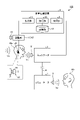
- FIG. 1 is a schematic diagram showing a pronunciation feedback device according to the first embodiment.
- FIG. 2 is a functional block diagram showing a voice processing device according to the first embodiment.
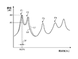
- FIG. 3 is a diagram for explaining the formant shift according to the first embodiment.
- FIG. 4 is a diagram for explaining the formant shift according to the first embodiment.
- FIG. 5 is a flowchart showing a pronunciation feedback method according to the first embodiment.
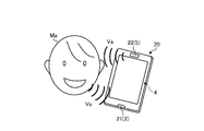
- FIG. 6 is a diagram for explaining a first application example of the pronunciation feedback device according to the first embodiment.
- FIG. 7 is a diagram for explaining a second application example of the pronunciation feedback device according to the first embodiment.
- FIG. 8 is a schematic diagram showing a pronunciation feedback device according to a modified example of the first embodiment.
- FIG. 9 is a schematic diagram showing a pronunciation feedback device according to the second embodiment.
- FIG. 10 is a diagram for explaining the frequency characteristics of the earphone according to the second embodiment.
- FIG. 1 is a schematic diagram showing a pronunciation feedback device 1 according to the present embodiment.
- the pronunciation feedback device 1 includes a microphone 2, a communicator 3, a voice processing device 4, and a speaker 5.
- Speaker Ma emits voice.
- the voice emitted by the speaker Ma is appropriately referred to as the original voice Vo.
- the original voice Vo emitted by the speaker Ma is input to the microphone 2 as an air conduction sound.
- Air-conducted sound is a sound that propagates in the air.
- the microphone 2 converts the original voice Vo emitted by the speaker Ma into the original voice data.
- the microphone 2 is connected to the communicator 3.
- the original voice data from the microphone 2 is transmitted from the communicator 3 to another communicator 7 via the transmission device 6.
- the speaker 8 is connected to the communicator 7.
- the speaker 8 converts the original audio data into the reproduced audio Vp.
- the reproduced audio Vp is output from the speaker 8.
- the frequency characteristics of the original voice Vo and the frequency characteristics of the reproduced voice Vp are similar. The viewer Mb can hear the reproduced audio Vp output from the speaker 8.
- the communicator 3 transmits the original voice data from the microphone 2 to the voice processing device 4.
- the voice processing device 4 has an acquisition unit 9, a processing unit 10, an output unit 11, and a storage unit 12.
- the acquisition unit 9 acquires the original voice data indicating the original voice Vo emitted by the speaker Ma.
- the original voice Vo is an air-conducted sound.
- the acquisition unit 9 acquires the original voice data from the microphone 2 via the communicator 3.
- the processing unit 10 adjusts the acoustic feature amount of the original audio data acquired by the acquisition unit 9 to generate the reproduced audio data indicating the reproduced audio Va.
- the output unit 11 outputs the reproduced audio data generated by the processing unit 10 to the speaker 5.
- the speaker 5 converts the reproduced audio data into the reproduced audio Va.
- the reproduced sound Va is output from the speaker 5.
- the speaker Ma can hear the reproduced voice Va output from the speaker 5.
- the acoustic feature amount of the reproduced voice Va matches or resembles the acoustic feature amount of the mixed sound of the bone conduction sound and the air conduction sound of the speaker Ma.
- the bone conduction sound is a sound in which the vibration of the vocal cords of the speaker Ma is transmitted to the auditory nerve of the speaker Ma through the skull of the speaker Ma.
- the air-conducted sound is a sound in which the original voice Vo emitted by the speaker Ma is transmitted to the auditory nerve of the speaker Ma through the air and the eardrum of the speaker Ma. Normally, the voice perceived by the speaker Ma when the speaker Ma emits the original voice Vo is a mixed sound of the bone-conducted sound and the air-conducted sound.
- the processing unit 10 outputs the reproduced voice data so that the speaker 5 outputs the reproduced voice Va indicating the acoustic feature amount that matches or is similar to the acoustic feature amount of the mixed sound of the bone conduction sound and the air conduction sound of the speaker Ma. To generate.
- the mixed sound of the bone-conducted sound and the air-conducted sound of the speaker Ma is appropriately referred to as a self-perceived voice.
- the self-perceived voice is a voice perceived by the speaker Ma when the speaker Ma emits the original voice Vo.
- the processing unit 10 generates reproduced voice data so that the self-perceived voice is output from the speaker 5.
- FIG. 2 is a functional block diagram showing a voice processing device 4 according to the present embodiment.
- the voice processing device 4 includes a computer.
- the voice processing device 4 has a processor 41, a main memory 42, a storage 43, and an interface 44.
- a processor 41 a CPU (Central Processing Unit) or an MPU (Micro Processing Unit) is exemplified.
- main memory 42 a non-volatile memory or a volatile memory is exemplified.
- a ROM (Read Only Memory) is exemplified as the non-volatile memory.
- a RAM Random Access Memory
- As the storage 43 a hard disk drive (HDD: Hard Disk Drive) or a solid state drive (SSD: Solid State Drive) is exemplified.
- An input / output circuit or a communication circuit is exemplified as the interface 44.
- the computer program 45 is expanded in the main memory 42.
- the processor 41 executes the pronunciation feedback method according to the present embodiment according to the computer program 45.
- the interface 44 is connected to each of the communicator 3 and the speaker 5.
- the processor 41 functions as a processing unit 10.
- the storage 43 functions as a storage unit 12.
- the interface 44 functions as an acquisition unit 9 and an output unit 11.
- the acoustic feature amount of the original voice data adjusted by the processing unit 10 includes the frequency band of the original voice Vo, the pitch of the original voice Vo, and the formant of the original voice Vo.
- the processing unit 10 includes a filter processing unit 13 that limits the frequency band of the original voice Vo to an audible band, a pitch shift processing unit 14 that pitch-shifts the original voice Vo, and a formant shift processing unit 15 that formant shifts the original voice Vo. including.
- the filter processing unit 13 extracts only the original voice data in the audible band from the original voice data acquired by the acquisition unit 9.
- the audible band refers to the frequency range of speech that can be perceived by humans.
- the human audible band is, for example, 15 [Hz] or more and 20 [kHz] or less.
- the filter processing unit 13 includes a low-pass filter that passes the original audio data having a frequency of 20 [kHz] or less, and a high-pass filter that passes the original audio data having a frequency of 15 [Hz] or more.
- the filter processing unit 13 may include a bandpass filter that passes original audio data of 15 [Hz] or more and 20 [kHz] or less.
- the processing unit 10 does not have to include the filter processing unit 13.
- the original audio data that has passed through the filter processing unit 13 is input to the pitch shift processing unit 14.
- the pitch shift processing unit 14 pitch shifts the original audio data.
- Pitch refers to the frequency of the fundamental tone of voice.
- the pitch affects the pitch.
- the pitch is made by the human vocal cords.
- the male pitch is, for example, 100 [Hz] or more and 150 [Hz] or less.
- the female pitch is, for example, 250 [Hz] or more and 300 [Hz] or less.
- Pitch shift means shifting the pitch based on a predetermined pitch shift condition.
- the pitch shift condition includes a pitch shift direction and a pitch shift amount Dp.
- the pitch shift direction includes the high frequency side or the low frequency side. That is, the pitch shift means shifting the pitch to the high frequency side or the low frequency side by a predetermined pitch shift amount Dp.
- the original voice data that has passed through the pitch shift processing unit 14 is input to the formant shift processing unit 15.
- the formant shift processing unit 15 formant shifts the original voice data.
- Formant is a frequency component that is emphasized by the resonance of the vocal tract. Formants affect the timbre. Formants are created by the human vocal tract. Formants vary from person to person. The formant with the lowest frequency is called the first formant. The formant whose frequency is the second lowest after the first formant is called the second formant. The first formant and the second formant are the elements that determine the vowel. Formants with frequencies higher than the third formant are the factors that shape the gender difference or the characteristics of the human voice. The first formant is, for example, 600 [Hz] or more and 800 [Hz] or less. The second formant is, for example, 1100 [Hz] or more and 1900 [Hz] or less.
- Formant shift means to shift the formant based on the predetermined formant shift condition.
- the formant shift condition includes the formant shift direction and the formant shift amount Df.
- the formant shift direction includes the high frequency side or the low frequency side. That is, the formant shift means to shift the formant to the high frequency side or the low frequency side by a predetermined formant shift amount Df.
- the pitch shift condition and the formant shift condition are predetermined and stored in the storage unit 12.
- the pitch shift processing unit 14 shifts the pitch based on the pitch shift conditions stored in the storage unit 12.
- the formant shift processing unit 15 performs formant shift based on the formant shift condition stored in the storage unit 12.
- the pitch shift direction and the formant shift direction are the same. That is, when the formant shift processing unit 15 formant shifts to the high frequency side, the pitch shift processing unit 14 pitch shifts to the high frequency side. When the formant shift processing unit 15 formant shifts to the low frequency side, the pitch shift processing unit 14 pitch shifts to the low frequency side.
- the pitch shift processing unit 14 pitch shifts without changing the pitch amplitude.
- the formant shift processing unit 15 shifts the formant without changing the amplitude of the formant.
- the pitch shift processing unit 14 and the formant shift processing unit 15 perform only the pitch shift and the formant shift with high accuracy, respectively, so that the amplitude is not changed.
- the pitch shift processing unit 14 and the formant shift processing unit 15 may change the amplitude.
- the output unit 11 may change the amplitude of a predetermined frequency.
- the processing unit 10 generates reproduced voice data so that the self-perceived voice, which is a mixed sound of the bone conduction sound and the air conduction sound of the speaker Ma, is output from the speaker 5.
- the formant shift processing unit 15 formant shifts to the high frequency side.
- the pitch shift processing unit 14 pitch shifts to the high frequency side.
- the pitch shift amount Dp and the formant shift amount Df for converting the original voice Vo into the reproduced voice Va which is a self-perceived voice can be derived statistically, for example, and are stored in advance in the storage unit 12.
- the pitch shift processing unit 14 pitch shifts to the higher frequency side by the pitch shift amount Dp stored in the storage unit 12.
- the formant shift processing unit 15 formant shifts to the high frequency side by the formant shift amount Df stored in the storage unit 12.
- the pitch shift amount Dp and formant shift amount Df for converting the original voice Vo into the reproduced voice Va which is a self-perceived voice may be determined for each speaker Ma.
- the pitch shift amount Dp may be variable.
- the formant shift amount Df may be variable.
- FIGS. 3 and 4 are diagrams for explaining the formant shift according to the present embodiment.
- the horizontal axis represents frequency [Hz] and the vertical axis represents amplitude [dB].
- the horizontal axis is a linear scale.
- the formant of the original audio data includes a first formant F1, a second formant F2, a third formant F3, and a fourth formant F4.
- the form shift processing unit 15 performs orthogonal transformation processing such as a fast Fourier transform (FFT) on the original voice data, and calculates the frequency characteristics of the original voice data including the envelope L0 of the formant.
- the envelope L0 is formed so as to connect the maximum amplitude values (maximum power values) of the plurality of frequencies.
- the formant shift processing unit 15 formant shifts at least a part of the formant envelope L0 to the high frequency side by the formant shift amount Df.
- the formant shift processing unit 15 may formant shift the envelope L0 of the first formant F1 and the second formant F2 to the high frequency side by the formant shift amount Df.
- the envelope L0 is formant-shifted to generate the envelope L1 of the first formant F1 and the second formant F2.
- the formant shift direction of the first formant F1 and the formant shift direction of the second formant F2 are the same.
- the formant shift amount Df of the first formant F1 and the formant shift amount Df of the second formant F2 are the same.
- the formant shift processing unit 15 formant shifts the first formant F1 and the second formant F2 without changing the amplitude of the first formant F1 and the amplitude of the second formant F2.
- the formant shift amount Df of the first formant F1 and the formant shift amount Df of the second formant F2 may be different.
- the formant shift processing unit 15 may formant shift the entire formant envelope L0 to the high frequency side by the formant shift amount Df.
- the entire formant envelope L0 in FIG. 4 is a range including the first formant F1 to the fourth formant F4.
- the formant shift amount Df may be determined based on the peak frequency P0 of the first formant F1.
- the formant shift processing unit 15 calculates the amplitude A1 which is 80 [%] of the amplitude A0 and the frequency P1 of the first formant F1 at the amplitude A1. ..
- the formant shift amount Df may be set so as not to exceed the difference between the peak frequency P0 and the frequency P1.
- the formant shift amount Df may be the difference between the peak frequency P0 and the frequency P1.
- the amplitude A1 may be 70 [%] or more and less than 100 [%] of the amplitude A0, and is preferably about 80 [%] of the amplitude A0.
- the entire formant envelope L0 does not have to be shifted. As long as the time change of the fundamental frequency, the time information of the amplitude envelope, and the like are retained, only a predetermined frequency range including the peak may be shifted on the envelope L0.
- the original audio data is converted into reproduced audio data by being processed by each of the filter processing unit 13, the pitch shift processing unit 14, and the formant shift processing unit 15.
- the reproduced voice Va is reproduced by the speaker 5.
- the speaker Ma can hear the reproduced voice Va output from the speaker 5.
- FIG. 5 is a flowchart showing a pronunciation feedback method according to the present embodiment.
- the computer program 45 can cause the voice processing device 4 to execute the pronunciation feedback method.
- Speaker Ma emits the original voice Vo toward the microphone 2.
- the acquisition unit 9 acquires the original voice data indicating the original voice Vo emitted by the speaker Ma (step S1).
- the filter processing unit 13 limits the frequency band of the original audio data to the audible band (step S2). Note that step S2 is an arbitrary process.
- the pitch shift processing unit 14 pitch shifts the original audio data that has passed through the filter processing unit 13 (step S3).
- the formant shift processing unit 15 formant shifts the original audio data that has passed through the pitch shift processing unit 14 (step S4).
- Step S3 and step S4 the processing unit 10 generates reproduced voice data so that the self-perceived voice is output from the speaker 5.
- the processing unit 10 may generate reproduced audio data indicating the reproduced audio Va in steps S2, S3, and S4.
- the order of step S2, step S3, and step S4 is arbitrary.
- the output unit 11 outputs the reproduced audio data generated by the processing unit 10 to the speaker 5 (step S5).
- the speaker 5 outputs the reproduced voice Va to the speaker Ma.
- the reproduced voice Va output from the speaker 5 is similar to the self-perceived voice of the speaker Ma.
- FIG. 6 is a diagram for explaining a first application example of the pronunciation feedback device 1 according to the present embodiment.
- FIG. 6 shows an example in which the pronunciation feedback device 1 is applied to the mobile phone 20.
- the mobile phone 20 has a mouthpiece 21 and a mouthpiece 22.
- the microphone 2 is arranged at the mouthpiece 21.
- the speaker 5 is arranged in the earpiece 22.
- the voice processing device 4 is arranged inside the mobile phone 20.
- the speaker Ma when making a call in a noisy environment, the speaker Ma may speak louder or louder than usual because it is difficult to hear the voice emitted by the speaker Ma.
- the original voice Vo emitted by the speaker Ma to the mouthpiece 21 is converted into the reproduced voice Va in the voice processing device 4.
- the reproduced sound Va is output from the earpiece 22.
- the speaker Ma can speak while listening to the reproduced voice Va, which is a self-perceived voice. Therefore, when making a call in a noisy environment, it is possible to prevent the speaker Ma from speaking in a louder voice or in a higher voice than usual.
- FIG. 7 is a diagram for explaining a second application example of the pronunciation feedback device 1 according to the present embodiment.
- FIG. 7 shows an example in which the pronunciation feedback device 1 is applied to the singing practice device 30.
- the singing practice device 30 has a microphone 2 supported by a microphone stand 31 and a monitor speaker 32 including a speaker 5.
- the voice processing device 4 is arranged between the microphone 2 and the monitor speaker 32.
- the pitch of the singing is often stable.
- the original voice Vo which is the singing voice emitted by the speaker Ma to the microphone 2
- the reproduced audio Va is output from the monitor speaker 32.
- the speaker Ma can sing while listening to the reproduced voice Va, which is a self-perceived voice. As a result, the pitch of the speaker Ma's singing is stabilized.
- the processing unit 10 adjusts the acoustic feature amount of the original voice data indicating the original voice Vo emitted by the speaker Ma.
- the processing unit 10 adjusts the acoustic feature amount of the original voice data to generate the reproduced voice data indicating the reproduced voice Va.
- the output unit 11 outputs the reproduced audio data to the speaker 5.
- the speaker 5 outputs the reproduced voice Va to the speaker Ma.
- the appropriate reproduced voice Va is fed back to the speaker Ma. Since the reproduced voice Va is properly fed back to the speaker Ma, the phenomenon that the speaker Ma speaks in a louder voice or a higher voice than usual in a noisy environment is suppressed.
- Pitch shift and formant shift are effective when converting the original voice Vo into the reproduced voice Va which is a self-perceived voice. Further, when converting the original voice Vo into the reproduced voice Va which is a self-perceived voice, it is effective to match the formant shift direction and the pitch shift direction.
- the original voice Vo when converting the original voice Vo into the reproduced voice Va which is a self-perceived voice, it is effective to perform a filter process for limiting the frequency band of the original voice Vo to the audible band before the pitch shift and the formant shift. ..
- FIG. 8 is a schematic diagram showing a pronunciation feedback device 101 according to a modified example of the present embodiment.
- the pitch shift condition and the formant shift condition are stored in the storage unit 12 in advance.
- the sounding feedback device 101 may include an operating device 16 for adjusting pitch shift conditions and formant shift conditions.
- the operation device 16 is connected to the voice processing device 4.
- the operating device 16 has a pitch slider 16A for adjusting the pitch shift condition and a formant slider 16B for adjusting the formant shift condition. By sliding the pitch slider 16A, the pitch shift conditions including the pitch shift direction and the pitch shift amount Dp are changed.
- the formant shift conditions including the formant shift direction and the formant shift amount Df are changed.
- the speaker Ma can operate the operation device 16 so that the reproduced voice Va approaches the self-perceived voice while listening to the reproduced voice Va output from the speaker 5.
- the reproduced voice Va is a self-perceived voice.
- the reproduced voice Va does not have to be a self-perceived voice.
- the pitch shift processing unit 14 may pitch shift to the low frequency side.
- the formant shift processing unit 15 may perform formant shift to the low frequency side.
- the pitch shift and formant shift may be performed to the extent that the speaker Ma can perceive the change in pitch and the change in formant.
- the speaker Ma can properly perform voice generation and voice perception. Since the voice generation and the voice perception are properly performed, the phenomenon that the speaker Ma's voice becomes difficult to recognize due to the stuttering or the bad tongue of the speaker Ma is suppressed.
- the acoustic feature amount of the original voice data may be adjusted so that the speaker Ma can properly recognize the reproduced voice Va output from the speaker 5. .
- FIG. 9 is a schematic diagram showing the pronunciation feedback device 102 according to the present embodiment.
- the output unit 11 outputs the reproduced audio data to the earphone 50 including the speaker 5.
- the earphone 50 is an inner earphone inserted into the ear canal of the speaker Ma.
- the earphone 50 outputs the reproduced sound Va in the ear canal.
- the earphone 50 includes an earpiece 51 that comes into contact with the inner surface of the ear canal.
- the earpiece 51 also functions as earplugs.
- the earpiece 51 is made of, for example, rubber, silicone, urethane, or the like.
- the earpiece 51 may be made of a soft material that deforms when pressed with a finger.
- the frequency characteristics of the external voice Vn transmitted to the eardrum of the speaker Ma change depending on the shape of the earpiece 51.
- External voice Vn refers to voice transmitted to the eardrum from the outside of the ear canal.
- noise around the speaker Ma is exemplified.
- the shape of the earpiece 51 includes the shape when the earpiece 51 is deformed.
- the deformation of the earpiece 51 also changes the frequency characteristics of the external voice Vn transmitted to the eardrum of the speaker Ma.
- FIG. 10 is a diagram for explaining the frequency characteristics of the earphone 50 according to the present embodiment. As in the lines HA, HB, HC, and HD shown in FIG. 10, the frequency characteristics of the external voice Vn transmitted to the eardrum of the speaker Ma change due to the change in the shape of the earpiece 51.
- the line HA shows the frequency characteristics of the external voice Vn related to the earpiece 51 having the first diameter.
- the line HB shows the frequency characteristics of the external voice Vn relating to the earpiece 51 having a second diameter larger than the first diameter.
- the line HC shows the frequency characteristics of the external voice Vn related to the earpiece 51 having a third diameter larger than the second diameter.
- the line HD shows the frequency characteristics of the external voice Vn related to the earpiece 51 having a fourth diameter larger than the third diameter.
- the earpiece 51 having the first diameter is most loosely inserted into the ear canal.
- the earpiece 51 having the first diameter is inserted into the ear canal with almost no deformation.
- the earpiece 51 having a fourth diameter is most tightly inserted into the ear canal.
- the earpiece 51 having a fourth diameter is inserted into the ear canal in the most deformed state.
- the fourth diameter earpiece 51 most seals the ear canal.
- a microphone is placed near the eardrum of the speaker Ma, and each of the four earpieces 51 is inserted into the ear canal, and the external voice Vn is input to the ear canal to be transmitted to the eardrum of the speaker Ma.
- the frequency characteristics of the external voice Vn can be measured.
- a signal having a predetermined frequency pattern such as an impulse sound may be used, or various noises such as a running sound of a train or an automobile may be used.
- the high frequency band referred to here is a frequency band of 1000 [Hz] or more and 20 [kHz] or less.
- the processing unit 10 includes an adjusting unit 17 for adjusting the frequency characteristics of the reproduced audio Va.
- the adjusting unit 17 adjusts the frequency characteristics of the reproduced voice Va transmitted from the speaker 5 of the earphone 50 to the eardrum of the speaker Ma so as to simulate the shape of the earpiece 51 of the earphone 50.
- the storage unit 12 stores the frequency characteristics shown by the lines HA, HB, HC, and HD.
- the adjusting unit 17 has a gain control function for adjusting the gain of the reproduced sound Va.
- the storage unit 12 is not limited to the frequency characteristics shown by the lines HA, HB, HC, and HD, and may store a plurality of different frequency characteristics in a predetermined frequency band.
- the processing unit 10 includes a filter processing unit 13, a pitch shift processing unit 14, and a formant shift processing unit 15. Playback audio data is output from the formant shift processing unit 15.
- the adjusting unit 17 adjusts the frequency characteristics (gain) of the reproduced audio data output from the formant shift processing unit 15.
- the operating device 18 is connected to the adjusting unit 17.
- the operating device 18 includes a rotatable knob. Based on the operation amount of the operating device 18, the adjusting unit 17 determines the frequency characteristics of the reproduced voice Va as the frequency characteristics indicated by the line HA, the frequency characteristics indicated by the line HB, the frequency characteristics indicated by the line HC, and the frequency indicated by the line HD. Change to each of the characteristics.
- the adjusting unit 17 adjusts the volume of the reproduced sound Va output from the speaker 5 based on the operation amount of the operating device 18.
- the adjusting unit 17 changes the volume of the reproduced voice Va so as to be linked with the change of the frequency characteristic of the reproduced voice Va based on the operation amount of the operating device 18.
- the frequency characteristic of the reproduced voice Va is adjusted to the frequency characteristic indicated by the line HA
- the volume of the reproduced voice Va is adjusted to the first volume.
- the volume of the reproduced voice Va is adjusted to the second volume smaller than the first volume.
- the volume of the reproduced voice Va is adjusted to a third volume smaller than the second volume.
- the volume of the reproduced voice Va is adjusted to the fourth volume which is smaller than the third volume.
- the speaker Ma can hear the clear reproduced voice Va at the first volume.
- the speaker Ma can hear the muffled reproduced voice Va at the fourth volume.
- the speaker Ma can adjust the frequency characteristics of the reproduced voice Va and the volume of the reproduced voice Va according to the preference of the speaker Ma.
Landscapes
- Engineering & Computer Science (AREA)
- Acoustics & Sound (AREA)
- Physics & Mathematics (AREA)
- Signal Processing (AREA)
- Health & Medical Sciences (AREA)
- Human Computer Interaction (AREA)
- Audiology, Speech & Language Pathology (AREA)
- Quality & Reliability (AREA)
- Computational Linguistics (AREA)
- Multimedia (AREA)
- General Health & Medical Sciences (AREA)
- Neurosurgery (AREA)
- Otolaryngology (AREA)
- Circuit For Audible Band Transducer (AREA)
Abstract
発話者に適正な音声をフィードバックする発音フィードバック装置を提供する。発音フィードバック装置は、発話者が発した原音声を示す原音声データを取得する取得部と、原音声データの音響特徴量を調整して再生音声を示す再生音声データを生成する処理部と、再生音声データを出力する出力部と、を備える。
Description
本発明は、発音フィードバック装置、発音フィードバック方法、及びコンピュータプログラムに関する。
特許文献1には、スピーカ付きマイクが開示されている。発話者がマイクに発した音声は、スピーカから発話者にフィードバックされる。
雑音環境下においては、発話者は普段よりも大きい声又は高い声で話してしまう可能性がある。また、発話者の吃音又は活舌の悪さに起因して、発話者の音声を認識し難くなる可能性がある。このような不具合を抑制するためには、発話者に適正な音声をフィードバックすることが有効である。
本発明は、発話者に適正な音声をフィードバックすることを目的とする。
本発明の一態様に係る発音フィードバック装置は、発話者が発した原音声を示す原音声データを取得する取得部と、前記原音声データの音響特徴量を調整して再生音声を示す再生音声データを生成する処理部と、前記再生音声データを出力する出力部と、を備える。
本発明の一態様に係る発音フィードバック方法は、発話者が発した原音声を示す原音声データを取得するステップと、前記原音声データの音響特徴量を調整して再生音声を示す再生音声データを生成するステップと、前記再生音声データを出力するステップと、を含む。
本発明の一態様に係るコンピュータプログラムは、発話者が発した原音声を示す原音声データを取得するステップと、前記原音声データの音響特徴量を調整して再生音声を示す再生音声データを生成するステップと、前記再生音声データを出力するステップと、を含む発音フィードバック方法を、コンピュータに実行させる。
本発明によれば、発話者に適正な音声をフィードバックすることができる。
以下に、本発明の実施形態を図面に基づいて詳細に説明する。なお、以下に説明する実施形態により本発明が限定されるものではない。
[第1実施形態]
(発音フィードバック装置)
図1は、本実施形態に係る発音フィードバック装置1を示す模式図である。図1に示すように、発音フィードバック装置1は、マイクロホン2と、コミュニケータ3と、音声処理装置4と、スピーカ5とを備える。
(発音フィードバック装置)
図1は、本実施形態に係る発音フィードバック装置1を示す模式図である。図1に示すように、発音フィードバック装置1は、マイクロホン2と、コミュニケータ3と、音声処理装置4と、スピーカ5とを備える。
発話者Maは、音声を発する。本実施形態において、発話者Maが発した音声を適宜、原音声Vo、と称する。発話者Maが発した原音声Voは、気導音として、マイクロホン2に入力される。気導音とは、空中を伝播する音をいう。
マイクロホン2は、発話者Maが発した原音声Voを原音声データに変換する。マイクロホン2は、コミュニケータ3に接続される。マイクロホン2からの原音声データは、伝送装置6を介してコミュニケータ3から別のコミュニケータ7に伝送される。コミュニケータ7にスピーカ8が接続される。スピーカ8は、原音声データを再生音声Vpに変換する。再生音声Vpは、スピーカ8から出力される。原音声Voの周波数特性と再生音声Vpの周波数特性とは類似する。視聴者Mbは、スピーカ8から出力された再生音声Vpを聞くことができる。
コミュニケータ3は、マイクロホン2からの原音声データを音声処理装置4に送信する。
音声処理装置4は、取得部9と、処理部10と、出力部11と、記憶部12とを有する。
取得部9は、発話者Maが発した原音声Voを示す原音声データを取得する。原音声Voは、気導音である。取得部9は、コミュニケータ3を介してマイクロホン2から原音声データを取得する。
処理部10は、取得部9により取得された原音声データの音響特徴量を調整して、再生音声Vaを示す再生音声データを生成する。
出力部11は、処理部10により生成された再生音声データをスピーカ5に出力する。スピーカ5は、再生音声データを再生音声Vaに変換する。再生音声Vaは、スピーカ5から出力される。発話者Maは、スピーカ5から出力された再生音声Vaを聞くことができる。
本実施形態において、再生音声Vaの音響特徴量は、発話者Maの骨導音と気導音との混合音の音響特徴量と一致又は類似する。骨導音とは、発話者Maの声帯の振動が発話者Maの頭蓋骨を介して発話者Maの聴覚神経に伝わる音をいう。気導音とは、発話者Maが発した原音声Voが空気及び発話者Maの鼓膜を介して発話者Maの聴覚神経に伝わる音をいう。通常、発話者Maが原音声Voを発したときに発話者Maが知覚する音声は、骨導音と気導音との混合音である。処理部10は、スピーカ5から発話者Maの骨導音と気導音との混合音の音響特徴量と一致又は類似する音響特徴量を示す再生音声Vaが出力されるように、再生音声データを生成する。
本実施形態において、発話者Maの骨導音と気導音との混合音を適宜、自己知覚音声、と称する。自己知覚音声は、発話者Maが原音声Voを発したときに発話者Maが知覚する音声である。処理部10は、自己知覚音声がスピーカ5から出力されるように、再生音声データを生成する。
(音声処理装置)
図2は、本実施形態に係る音声処理装置4を示す機能ブロック図である。音声処理装置4は、コンピュータを含む。音声処理装置4は、プロセッサ41と、メインメモリ42と、ストレージ43と、インタフェース44とを有する。プロセッサ41として、CPU(Central Processing Unit)又はMPU(Micro Processing Unit)が例示される。メインメモリ42として、不揮発性メモリ又は揮発性メモリが例示される。不揮発性メモリとして、ROM(Read Only Memory)が例示される。揮発性メモリとして、RAM(Random Access Memory)が例示される。ストレージ43として、ハードディスクドライブ(HDD:Hard Disk Drive)又はソリッドステートドライブ(SSD:Solid State Drive)が例示される。インタフェース44として、入出力回路又は通信回路が例示される。
図2は、本実施形態に係る音声処理装置4を示す機能ブロック図である。音声処理装置4は、コンピュータを含む。音声処理装置4は、プロセッサ41と、メインメモリ42と、ストレージ43と、インタフェース44とを有する。プロセッサ41として、CPU(Central Processing Unit)又はMPU(Micro Processing Unit)が例示される。メインメモリ42として、不揮発性メモリ又は揮発性メモリが例示される。不揮発性メモリとして、ROM(Read Only Memory)が例示される。揮発性メモリとして、RAM(Random Access Memory)が例示される。ストレージ43として、ハードディスクドライブ(HDD:Hard Disk Drive)又はソリッドステートドライブ(SSD:Solid State Drive)が例示される。インタフェース44として、入出力回路又は通信回路が例示される。
コンピュータプログラム45がメインメモリ42に展開される。プロセッサ41は、コンピュータプログラム45に従って、本実施形態に係る発音フィードバック方法を実行する。インタフェース44は、コミュニケータ3及びスピーカ5のそれぞれと接続される。
プロセッサ41は、処理部10として機能する。ストレージ43は、記憶部12として機能する。インタフェース44は、取得部9及び出力部11として機能する。
本実施形態において、処理部10により調整される原音声データの音響特徴量は、原音声Voの周波数帯域、原音声Voのピッチ、及び原音声Voのフォルマントを含む。処理部10は、原音声Voの周波数帯域を可聴帯域に制限するフィルタ処理部13と、原音声Voをピッチシフトするピッチシフト処理部14と、原音声Voをフォルマントシフトするフォルマントシフト処理部15とを含む。
フィルタ処理部13は、取得部9により取得された原音声データから可聴帯域の原音声データのみを抽出する。可聴帯域とは、ヒトが知覚可能な音声の周波数範囲をいう。ヒトの可聴帯域は、例えば15[Hz]以上20[kHz]以下である。フィルタ処理部13は、20[kHz]以下の周波数の原音声データを通過させるローパスフィルタと、15[Hz]以上の周波数の原音声データを通過させるハイパスフィルタとを含む。なお、フィルタ処理部13は、15[Hz]以上20[kHz]以下の原音声データを通過させるバンドパスフィルタを含んでもよい。なお、処理部10は、フィルタ処理部13を含まなくてもよい。
フィルタ処理部13を通過した原音声データは、ピッチシフト処理部14に入力される。ピッチシフト処理部14は、原音声データをピッチシフトする。
ピッチとは、音声の基音の周波数をいう。ピッチは、音程に影響する。ピッチは、ヒトの声帯により作られる。男性のピッチは、例えば100[Hz]以上150[Hz]以下である。女性のピッチは、例えば250[Hz]以上300[Hz]以下である。
ピッチシフトとは、所定のピッチシフト条件に基づいて、ピッチをシフトさせることをいう。ピッチシフト条件は、ピッチシフト方向及びピッチシフト量Dpを含む。ピッチシフト方向は、高周波数側又は低周波数側を含む。すなわち、ピッチシフトとは、ピッチを高周波数側又は低周波数側に所定のピッチシフト量Dpだけシフトさせることをいう。
ピッチシフト処理部14を通過した原音声データは、フォルマントシフト処理部15に入力される。フォルマントシフト処理部15は、原音声データをフォルマントシフトする。
フォルマントとは、声道の共鳴によって強調される周波数成分をいう。フォルマントは、音色に影響する。フォルマントは、ヒトの声道により作られる。フォルマントは、ヒトによって異なる。周波数が最も低いフォルマントは、第1フォルマントと呼ばれる。第1フォルマントに次いで周波数が低いフォルマントは、第2フォルマントと呼ばれる。第1フォルマント及び第2フォルマントは、母音を決定付ける要素である。第3フォルマントよりも高い周波数のフォルマントは、男女差又はヒトの声の特徴を形作る要素である。第1フォルマントは、例えば600[Hz]以上800[Hz]以下である。第2フォルマントは、例えば1100[Hz]以上1900[Hz]以下である。
フォルマントシフトとは、所定のフォルマントシフト条件に基づいて、フォルマントをシフトさせることをいう。フォルマントシフト条件は、フォルマントシフト方向及びフォルマントシフト量Dfを含む。フォルマントシフト方向は、高周波数側又は低周波数側を含む。すなわち、フォルマントシフトとは、フォルマントを高周波数側又は低周波数側に所定のフォルマントシフト量Dfだけシフトさせることをいう。
本実施形態において、ピッチシフト条件及びフォルマントシフト条件は、予め定められており、記憶部12に記憶されている。ピッチシフト処理部14は、記憶部12に記憶されているピッチシフト条件に基づいて、ピッチシフトする。フォルマントシフト処理部15は、記憶部12に記憶されているフォルマントシフト条件に基づいて、フォルマントシフトする。
本実施形態において、ピッチシフト方向とフォルマントシフト方向とは、同一である。すなわち、フォルマントシフト処理部15が高周波数側にフォルマントシフトした場合、ピッチシフト処理部14は高周波数側にピッチシフトする。フォルマントシフト処理部15が低周波数側にフォルマントシフトした場合、ピッチシフト処理部14は低周波数側にピッチシフトする。
ピッチシフト処理部14は、ピッチの振幅を変化させることなく、ピッチシフトする。フォルマントシフト処理部15は、フォルマントの振幅を変化させることなく、フォルマントシフトする。なお、ピッチシフト処理部14及びフォルマントシフト処理部15は、それぞれピッチシフト及びフォルマントシフトのみを精度よく行うため、振幅を変化させないとしている。ピッチシフト処理部14及びフォルマントシフト処理部15は、振幅を変化させてもよい。出力部11が、所定の周波数の振幅を変化させてもよい。
本実施形態において、処理部10は、発話者Maの骨導音と気導音との混合音である自己知覚音声がスピーカ5から出力されるように、再生音声データを生成する。フォルマントシフト処理部15は、高周波数側にフォルマントシフトする。ピッチシフト処理部14は、高周波数側にピッチシフトする。
原音声Voを自己知覚音声である再生音声Vaに変換するためのピッチシフト量Dp及びフォルマントシフト量Dfは、例えば統計的に導出することができ、記憶部12に予め記憶される。ピッチシフト処理部14は、記憶部12に記憶されているピッチシフト量Dpだけ高周波数側にピッチシフトする。フォルマントシフト処理部15は、記憶部12に記憶されているフォルマントシフト量Dfだけ高周波数側にフォルマントシフトする。
なお、原音声Voを自己知覚音声である再生音声Vaに変換するためのピッチシフト量Dp及びフォルマントシフト量Dfが、発話者Maごとに定められてもよい。ピッチシフト量Dpは、可変でもよい。フォルマントシフト量Dfは、可変でもよい。
図3及び図4のそれぞれは、本実施形態に係るフォルマントシフトを説明するための図である。図3及び図4に示すグラフにおいて、横軸は周波数[Hz]を示し、縦軸は振幅[dB]を示す。横軸は線形スケールである。図3及び図4に示す例において、原音声データのフォルマントは、第1フォルマントF1と、第2フォルマントF2と、第3フォルマントF3と、第4フォルマントF4とを含む。
フォルマントシフト処理部15は、原音声データについて高速フーリエ変換(FFT:Fast Fourier Transform)のような直交変換処理を実施して、フォルマントの包絡線L0を含む原音声データの周波数特性を算出する。包絡線L0は、複数の周波数のそれぞれの最大振幅値(最大パワー値)を結ぶように形成される。フォルマントシフト処理部15は、フォルマントの包絡線L0の少なくとも一部を高周波数側にフォルマントシフト量Dfだけフォルマントシフトする。
図3に示すように、フォルマントシフト処理部15は、第1フォルマントF1及び第2フォルマントF2の包絡線L0を高周波数側にフォルマントシフト量Dfだけフォルマントシフトしてもよい。包絡線L0がフォルマントシフトされることにより、第1フォルマントF1及び第2フォルマントF2の包絡線L1が生成される。第1フォルマントF1のフォルマントシフト方向と第2フォルマントF2のフォルマントシフト方向とは、同一である。第1フォルマントF1のフォルマントシフト量Dfと第2フォルマントF2のフォルマントシフト量Dfとは、同一である。フォルマントシフト処理部15は、第1フォルマントF1の振幅及び第2フォルマントF2の振幅を変化させることなく、第1フォルマントF1及び第2フォルマントF2をフォルマントシフトする。
なお、第1フォルマントF1のフォルマントシフト量Dfと第2フォルマントF2のフォルマントシフト量Dfとは、異なってもよい。
なお、図4に示すように、フォルマントシフト処理部15は、フォルマントの包絡線L0全体を高周波数側にフォルマントシフト量Dfだけフォルマントシフトしてもよい。図4におけるフォルマントの包絡線L0全体とは、第1フォルマントF1から第4フォルマントF4までを含む範囲である。
なお、フォルマントシフト量Dfは、第1フォルマントF1のピーク周波数P0に基づいて決定されてもよい。ピーク周波数P0における第1フォルマントF1の振幅がA0である場合、フォルマントシフト処理部15は、振幅A0の80[%]となる振幅A1と、振幅A1における第1フォルマントF1の周波数P1とを算出する。フォルマントシフト量Dfは、ピーク周波数P0と周波数P1との差を超えないように定められてもよい。フォルマントシフト量Dfは、ピーク周波数P0と周波数P1との差でもよい。なお、振幅A1は振幅A0の70[%]以上100[%]未満であればよく、振幅A0の80[%]程度とするのが好適である。
なお、フォルマントシフトにおいて、フォルマントの包絡線L0全体がシフトされなくてもよい。基本周波数の時間変化や振幅包絡の時間情報等が保持されていれば、包絡線L0においてピークを含む所定の周波数範囲だけをシフトさせてもよい。
原音声データは、フィルタ処理部13、ピッチシフト処理部14、及びフォルマントシフト処理部15のそれぞれで処理されることにより、再生音声データに変換される。再生音声Vaは、スピーカ5によって再生される。発話者Maは、スピーカ5から出力された再生音声Vaを聞くことができる。
(発音フィードバック方法)
図5は、本実施形態に係る発音フィードバック方法を示すフローチャートである。コンピュータプログラム45は、発音フィードバック方法を音声処理装置4に実行させることができる。
図5は、本実施形態に係る発音フィードバック方法を示すフローチャートである。コンピュータプログラム45は、発音フィードバック方法を音声処理装置4に実行させることができる。
発話者Maは、マイクロホン2に向かって原音声Voを発する。取得部9は、発話者Maが発した原音声Voを示す原音声データを取得する(ステップS1)。
フィルタ処理部13は、原音声データの周波数帯域を可聴帯域に制限する(ステップS2)。なお、ステップS2は任意の処理である。
ピッチシフト処理部14は、フィルタ処理部13を通過した原音声データをピッチシフトする(ステップS3)。
フォルマントシフト処理部15は、ピッチシフト処理部14を通過した原音声データをフォルマントシフトする(ステップS4)。
ステップS3及びステップS4により、再生音声Vaを示す再生音声データが生成される。処理部10は、ステップS3及びステップS4において、自己知覚音声がスピーカ5から出力されるように、再生音声データを生成する。処理部10は、ステップS2、ステップS3、及びステップS4により、再生音声Vaを示す再生音声データを生成してもよい。なお、ステップS2、ステップS3、及びステップS4の順序は任意である。
出力部11は、処理部10において生成された再生音声データをスピーカ5に出力する(ステップS5)。
スピーカ5は、再生音声Vaを発話者Maに出力する。スピーカ5から出力される再生音声Vaは、発話者Maの自己知覚音声と類似する。
(適用例)
図6は、本実施形態に係る発音フィードバック装置1の第1適用例を説明するための図である。図6は、発音フィードバック装置1が携帯電話20に適用された例を示す。携帯電話20は、送話口21と、受話口22とを有する。マイクロホン2が送話口21に配置される。スピーカ5が受話口22に配置される。音声処理装置4は、携帯電話20の内部に配置される。
図6は、本実施形態に係る発音フィードバック装置1の第1適用例を説明するための図である。図6は、発音フィードバック装置1が携帯電話20に適用された例を示す。携帯電話20は、送話口21と、受話口22とを有する。マイクロホン2が送話口21に配置される。スピーカ5が受話口22に配置される。音声処理装置4は、携帯電話20の内部に配置される。
例えば雑音環境下で電話する場合、発話者Maは、発話者Maが発した音声を聞き取り難いため、普段よりも大きい声で話したり高い声で話したりする可能性がある。本実施形態においては、発話者Maが送話口21に発した原音声Voが、音声処理装置4において再生音声Vaに変換される。再生音声Vaは、受話口22から出力される。発話者Maは、自己知覚音声である再生音声Vaを聞きながら話すことができる。したがって、雑音環境下で電話する場合において、発話者Maが普段よりも大きい声で話したり高い声で話したりすることが抑制される。
図7は、本実施形態に係る発音フィードバック装置1の第2適用例を説明するための図である。図7は、発音フィードバック装置1が歌唱練習装置30に適用された例を示す。歌唱練習装置30は、マイクスタンド31に支持されるマイクロホン2と、スピーカ5を含むモニタスピーカ32とを有する。音声処理装置4は、マイクロホン2とモニタスピーカ32との間に配置される。
発話者Maが自己認識音声である再生音声Vaを聞きながら歌唱すると、歌唱の音程が安定する場合が多い。本実施形態においては、発話者Maがマイクロホン2に発した歌唱音声である原音声Voが、音声処理装置4において再生音声Vaに変換される。再生音声Vaは、モニタスピーカ32から出力される。発話者Maは、自己知覚音声である再生音声Vaを聞きながら歌唱することができる。これにより、発話者Maの歌唱の音程は安定する。
(効果)
以上説明したように、本実施形態によれば、発話者Maが発した原音声Voを示す原音声データの音響特徴量が処理部10により調整される。処理部10は、原音声データの音響特徴量を調整して、再生音声Vaを示す再生音声データを生成する。出力部11は、再生音声データをスピーカ5に出力する。スピーカ5は、再生音声Vaを発話者Maに出力する。これにより、発話者Maに適正な再生音声Vaがフィードバックされる。発話者Maに適正は再生音声Vaがフィードバックされるので、雑音環境下で発話者Maが普段よりも大きい声で話したり高い声で話したりする現象が抑制される。
以上説明したように、本実施形態によれば、発話者Maが発した原音声Voを示す原音声データの音響特徴量が処理部10により調整される。処理部10は、原音声データの音響特徴量を調整して、再生音声Vaを示す再生音声データを生成する。出力部11は、再生音声データをスピーカ5に出力する。スピーカ5は、再生音声Vaを発話者Maに出力する。これにより、発話者Maに適正な再生音声Vaがフィードバックされる。発話者Maに適正は再生音声Vaがフィードバックされるので、雑音環境下で発話者Maが普段よりも大きい声で話したり高い声で話したりする現象が抑制される。
原音声Voを自己知覚音声である再生音声Vaに変換する場合、ピッチシフト及びフォルマントシフトが有効である。また、原音声Voを自己知覚音声である再生音声Vaに変換する場合、フォルマントシフト方向とピッチシフト方向とを一致させることが有効である。
また、原音声Voを自己知覚音声である再生音声Vaに変換する場合、ピッチシフト及びフォルマントシフトの前に、原音声Voの周波数帯域を可聴帯域に制限するフィルタ処理を実施することが有効である。
(変形例)
図8は、本実施形態の変形例に係る発音フィードバック装置101を示す模式図である。上述の実施形態においては、ピッチシフト条件及びフォルマントシフト条件が予め記憶部12に記憶されていることとした。図8に示すように、発音フィードバック装置101は、ピッチシフト条件及びフォルマントシフト条件を調整する操作装置16を備えてもよい。図8に示すように、操作装置16は、音声処理装置4に接続される。操作装置16は、ピッチシフト条件を調整するピッチスライダ16Aと、フォルマントシフト条件を調整するフォルマントスライダ16Bとを有する。ピッチスライダ16Aがスライドされることにより、ピッチシフト方向及びピッチシフト量Dpを含むピッチシフト条件が変更される。フォルマントスライダ16Bがスライドされることにより、フォルマントシフト方向及びフォルマントシフト量Dfを含むフォルマントシフト条件が変更される。発話者Maは、スピーカ5から出力される再生音声Vaを聞きながら、再生音声Vaが自己知覚音声に近付くように、操作装置16を操作することができる。
図8は、本実施形態の変形例に係る発音フィードバック装置101を示す模式図である。上述の実施形態においては、ピッチシフト条件及びフォルマントシフト条件が予め記憶部12に記憶されていることとした。図8に示すように、発音フィードバック装置101は、ピッチシフト条件及びフォルマントシフト条件を調整する操作装置16を備えてもよい。図8に示すように、操作装置16は、音声処理装置4に接続される。操作装置16は、ピッチシフト条件を調整するピッチスライダ16Aと、フォルマントシフト条件を調整するフォルマントスライダ16Bとを有する。ピッチスライダ16Aがスライドされることにより、ピッチシフト方向及びピッチシフト量Dpを含むピッチシフト条件が変更される。フォルマントスライダ16Bがスライドされることにより、フォルマントシフト方向及びフォルマントシフト量Dfを含むフォルマントシフト条件が変更される。発話者Maは、スピーカ5から出力される再生音声Vaを聞きながら、再生音声Vaが自己知覚音声に近付くように、操作装置16を操作することができる。
上述の実施形態においては、再生音声Vaが自己知覚音声であることとした。再生音声Vaは自己知覚音声でなくてもよい。また、ピッチシフト処理部14は、低周波数側にピッチシフトしてもよい。フォルマントシフト処理部15は、低周波数側にフォルマントシフトしてもよい。発話者Maがピッチの変化及びフォルマントの変化を知覚できる程度にピッチシフト及びフォルマントシフトが実施されればよい。再生音声Vaが発話者Maにフィードバックされることにより、発話者Maは、音声生成及び音声知覚を適正に行うことができる。音声生成及び音声知覚が適正に行われるので、発話者Maの吃音又は活舌の悪さに起因して、発話者Maの音声を認識し難くなる現象が抑制される。例えば英語学習において再生音声Vaを聞きながら発音練習をする場合、スピーカ5から出力される再生音声Vaを発話者Maが適正に認識できるように、原音声データの音響特徴量が調整されてもよい。
[第2実施形態]
第2実施形態について説明する。以下の説明において、上述の実施形態と同一又は同等の構成要素については同一の符号を付し、その構成要素の説明を簡略又は省略する。
第2実施形態について説明する。以下の説明において、上述の実施形態と同一又は同等の構成要素については同一の符号を付し、その構成要素の説明を簡略又は省略する。
図9は、本実施形態に係る発音フィードバック装置102を示す模式図である。本実施形態において、出力部11は、スピーカ5を含むイヤホン50に再生音声データを出力する。イヤホン50は、発話者Maの外耳道に挿入されるインナイヤホンである。イヤホン50は、外耳道において再生音声Vaを出力する。
イヤホン50は、外耳道の内面に接触するイヤピース51を含む。イヤピース51は、耳栓としても機能する。イヤピース51は、例えばゴム製、シリコーン製、及びウレタン製等である。なお、イヤピース51は、指で押すと変形する軟質材料で形成されていればよい。
イヤピース51の形状により、発話者Maの鼓膜に伝達される外部音声Vnの周波数特性が変化する。外部音声Vnとは、外耳道の外部から鼓膜に伝達される音声をいう。外部音声Vnとして、発話者Maの周囲の雑音が例示される。
イヤピース51の形状は、イヤピース51が変形した場合の形状を含む。イヤピース51が変形することによっても、発話者Maの鼓膜に伝達される外部音声Vnの周波数特性が変化する。
図10は、本実施形態に係るイヤホン50の周波数特性を説明するための図である。図10に示すラインHA,HB,HC,HDのように、イヤピース51の形状が変化することにより、発話者Maの鼓膜に伝達される外部音声Vnの周波数特性が変化する。
ラインHAは、第1直径のイヤピース51に係る外部音声Vnの周波数特性を示す。ラインHBは、第1直径よりも大きい第2直径のイヤピース51に係る外部音声Vnの周波数特性を示す。ラインHCは、第2直径よりも大きい第3直径のイヤピース51に係る外部音声Vnの周波数特性を示す。ラインHDは、第3直径よりも大きい第4直径のイヤピース51に係る外部音声Vnの周波数特性を示す。4形態のイヤピース51のうち、第1直径のイヤピース51は、最も緩めに外耳道に挿入される。第1直径のイヤピース51は、ほぼ変形しない状態で外耳道に挿入される。4形態のイヤピース51のうち、第4直径のイヤピース51は、最もきつめに外耳道に挿入される。第4直径のイヤピース51は、最も変形した状態で外耳道に挿入される。4形態のイヤピース51のうち、第4直径のイヤピース51は、外耳道を最も密閉する。
なお、発話者Maの鼓膜の近傍にマイクを配置し、4形態のイヤピース51のそれぞれを外耳道に挿入した状態で、外部音声Vnを外耳道に入力することにより、発話者Maの鼓膜に伝達される外部音声Vnの周波数特性を測定することができる。外部音声Vnは、インパルス音等の所定の周波数パターンを備えた信号を用いてもよいし、列車や自動車の走行音等の各種騒音を用いてもよい。
図10に示すように、イヤピース51の直径が大きくなるほど、鼓膜に対する外部音声Vnの遮断効果が高まり、特に高周波数帯域においてゲインが低下する。ここでいう高周波数帯域は、1000[Hz]以上20[kHz]以下の周波数帯域である。
図9に示すように、本実施形態において、処理部10は、再生音声Vaの周波数特性を調整する調整部17を含む。調整部17は、イヤホン50のイヤピース51の形状を模擬するように、イヤホン50のスピーカ5から発話者Maの鼓膜に伝達される再生音声Vaの周波数特性を調整する。記憶部12には、ラインHA,HB,HC,HDで示した周波数特性が記憶されている。調整部17は、再生音声Vaのゲインを調整するゲインコントロール機能を有する。なお、記憶部12には、ラインHA,HB,HC,HDで示した周波数特性に限らず、所定の周波数帯域における複数の異なる周波数特性が記憶されていてもよい。
上述の実施形態と同様、処理部10は、フィルタ処理部13、ピッチシフト処理部14、及びフォルマントシフト処理部15を含む。フォルマントシフト処理部15から再生音声データが出力される。調整部17は、フォルマントシフト処理部15から出力された再生音声データの周波数特性(ゲイン)を調整する。
調整部17に操作装置18が接続される。操作装置18は、回転可能なノブを含む。調整部17は、操作装置18の操作量に基づいて、再生音声Vaの周波数特性を、ラインHAで示す周波数特性、ラインHBで示す周波数特性、ラインHCで示す周波数特性、及びラインHDで示す周波数特性のそれぞれに変化させる。
本実施形態において、調整部17は、操作装置18の操作量に基づいて、スピーカ5から出力される再生音声Vaの音量を調整する。調整部17は、操作装置18の操作量に基づいて、再生音声Vaの周波数特性の変化と連動するように、再生音声Vaの音量を変化させる。再生音声Vaの周波数特性がラインHAで示す周波数特性に調整される場合、再生音声Vaの音量は、第1音量に調整される。再生音声Vaの周波数特性がラインHBで示す周波数特性に調整される場合、再生音声Vaの音量は、第1音量よりも小さい第2音量に調整される。再生音声Vaの周波数特性がラインHCで示す周波数特性に調整される場合、再生音声Vaの音量は、第2音量よりも小さい第3音量に調整される。再生音声Vaの周波数特性がラインHDで示す周波数特性に調整される場合、再生音声Vaの音量は、第3音量よりも小さい第4音量に調整される。
例えば、再生音声Vaの周波数特性がラインHAで示す周波数特性に調整されることにより、発話者Maは、クリアな再生音声Vaを第1音量で聞くことができる。再生音声Vaの周波数特性がラインHDで示す周波数特性に調整されることにより、発話者Maは、こもった再生音声Vaを第4音量で聞くことができる。発話者Maは、発話者Maの好みに合わせて再生音声Vaの周波数特性及び再生音声Vaの音量を調整することができる。
1…発音フィードバック装置、2…マイクロホン、3…コミュニケータ、4…音声処理装置、5…スピーカ、6…伝送装置、7…コミュニケータ、8…スピーカ、9…取得部、10…処理部、11…出力部、12…記憶部、13…フィルタ処理部、14…ピッチシフト処理部、15…フォルマントシフト処理部、16…操作装置、16A…ピッチスライダ、16B…フォルマントスライダ、17…調整部、18…操作装置、20…携帯電話、21…送話口、22…受話口、30…歌唱練習装置、31…マイクスタンド、32…モニタスピーカ、41…プロセッサ、42…メインメモリ、43…ストレージ、44…インタフェース、45…コンピュータプログラム、50…イヤホン、51…イヤピース、101…発音フィードバック装置、102…発音フィードバック装置、A0…振幅、A1…振幅、Df…フォルマントシフト量、Dp…ピッチシフト量、F1…第1フォルマント、F2…第2フォルマント、F3…第3フォルマント、F4…第4フォルマント、L0…包絡線、L1…包絡線、Ma…発話者、Mb…視聴者、P0…ピーク周波数、P1…周波数、Va…再生音声、Vn…外部音声、Vo…原音声、Vp…再生音声。
Claims (6)
- 発話者が発した原音声を示す原音声データを取得する取得部と、
前記原音声データの音響特徴量を調整して再生音声を示す再生音声データを生成する処理部と、
前記再生音声データを出力する出力部と、を備える、
発音フィードバック装置。 - 前記音響特徴量は、前記原音声のピッチ及びフォルマントを含み、
前記処理部は、ピッチシフトするピッチシフト処理部及びフォルマントシフトするフォルマントシフト処理部を含む、
請求項1に記載の発音フィードバック装置。 - 前記処理部は、高周波数側にフォルマントシフトした場合、高周波数側にピッチシフトし、低周波数側にフォルマントシフトした場合、低周波数側にピッチシフトする、
請求項2に記載の発音フィードバック装置。 - 前記音響特徴量は、前記原音声の周波数帯域を含み、
前記処理部は、前記周波数帯域を可聴帯域に制限するフィルタ処理部を含む、
請求項1から請求項3のいずれか一項に記載の発音フィードバック装置。 - 発話者が発した原音声を示す原音声データを取得するステップと、
前記原音声データの音響特徴量を調整して再生音声を示す再生音声データを生成するステップと、
前記再生音声データを出力するステップと、を含む、
発音フィードバック方法。 - 発話者が発した原音声を示す原音声データを取得するステップと、
前記原音声データの音響特徴量を調整して再生音声を示す再生音声データを生成するステップと、
前記再生音声データを出力するステップと、を含む発音フィードバック方法を、コンピュータに実行させる、
コンピュータプログラム。
Applications Claiming Priority (2)
| Application Number | Priority Date | Filing Date | Title |
|---|---|---|---|
| JP2020160162A JP2022053366A (ja) | 2020-09-24 | 2020-09-24 | 発音フィードバック装置、発音フィードバック方法、及びコンピュータプログラム |
| JP2020-160162 | 2020-09-24 |
Publications (1)
| Publication Number | Publication Date |
|---|---|
| WO2022065441A1 true WO2022065441A1 (ja) | 2022-03-31 |
Family
ID=80846652
Family Applications (1)
| Application Number | Title | Priority Date | Filing Date |
|---|---|---|---|
| PCT/JP2021/035137 Ceased WO2022065441A1 (ja) | 2020-09-24 | 2021-09-24 | 発音フィードバック装置、発音フィードバック方法、及びコンピュータプログラム |
Country Status (2)
| Country | Link |
|---|---|
| JP (1) | JP2022053366A (ja) |
| WO (1) | WO2022065441A1 (ja) |
Citations (2)
| Publication number | Priority date | Publication date | Assignee | Title |
|---|---|---|---|---|
| JPH10224898A (ja) * | 1997-01-31 | 1998-08-21 | Sanyo Electric Co Ltd | 補聴器 |
| JP2006501929A (ja) * | 2002-10-09 | 2006-01-19 | イースト カロライナ ユニバーシティ | 周波数変換したフィードバックを使用して非吃音性の病状を治療するための方法および装置 |
-
2020
- 2020-09-24 JP JP2020160162A patent/JP2022053366A/ja active Pending
-
2021
- 2021-09-24 WO PCT/JP2021/035137 patent/WO2022065441A1/ja not_active Ceased
Patent Citations (2)
| Publication number | Priority date | Publication date | Assignee | Title |
|---|---|---|---|---|
| JPH10224898A (ja) * | 1997-01-31 | 1998-08-21 | Sanyo Electric Co Ltd | 補聴器 |
| JP2006501929A (ja) * | 2002-10-09 | 2006-01-19 | イースト カロライナ ユニバーシティ | 周波数変換したフィードバックを使用して非吃音性の病状を治療するための方法および装置 |
Also Published As
| Publication number | Publication date |
|---|---|
| JP2022053366A (ja) | 2022-04-05 |
Similar Documents
| Publication | Publication Date | Title |
|---|---|---|
| CN1798452B (zh) | 实时补偿音频频率响应特性的方法和用该方法的声音系统 | |
| US8781836B2 (en) | Hearing assistance system for providing consistent human speech | |
| EP2640095B2 (en) | Method for fitting a hearing aid device with active occlusion control to a user | |
| US20250159398A1 (en) | Hearing Sensitivity Acquisition Methods and Devices | |
| CN104254049A (zh) | 头戴式耳机响应测量和均衡 | |
| CN107112026A (zh) | 用于智能语音识别和处理的系统、方法和装置 | |
| JP2010016429A (ja) | ハウリング検出装置およびハウリング検出方法 | |
| US10555108B2 (en) | Filter generation device, method for generating filter, and program | |
| US12249343B2 (en) | Natural ear | |
| US11727949B2 (en) | Methods and apparatus for reducing stuttering | |
| US10034087B2 (en) | Audio signal processing for listening devices | |
| Bouserhal et al. | An in-ear speech database in varying conditions of the audio-phonation loop | |
| CN107948785A (zh) | 耳机和对耳机执行自适应调整的方法 | |
| CN118338220A (zh) | 减轻耳鸣的助听器音频输出方法、音频输出设备及计算机可读存储介质 | |
| EP4007299B1 (en) | Audio output using multiple different transducers | |
| WO2022065441A1 (ja) | 発音フィードバック装置、発音フィードバック方法、及びコンピュータプログラム | |
| CN112995854A (zh) | 音频处理方法、装置及电子设备 | |
| US12593184B2 (en) | Hearing aid listening test presets | |
| EP4714131A1 (en) | Audio processing using hearing loss data | |
| CN115668370B (zh) | 听力设备自带的语音检测器 | |
| JP5395826B2 (ja) | 補聴器調整装置 | |
| US12614537B2 (en) | Wearable acoustic device, wearable acoustic system, and acoustic processing method | |
| CN110570875A (zh) | 检测环境噪音以改变播放语音频率的方法及声音播放装置 | |
| US12273675B2 (en) | Leakage compensation method and system for headphone | |
| CN115442707B (zh) | 一种扬声器模组功耗的降低方法及装置 |
Legal Events
| Date | Code | Title | Description |
|---|---|---|---|
| 121 | Ep: the epo has been informed by wipo that ep was designated in this application |
Ref document number: 21872570 Country of ref document: EP Kind code of ref document: A1 |
|
| DPE1 | Request for preliminary examination filed after expiration of 19th month from priority date (pct application filed from 20040101) | ||
| NENP | Non-entry into the national phase |
Ref country code: DE |
|
| 122 | Ep: pct application non-entry in european phase |
Ref document number: 21872570 Country of ref document: EP Kind code of ref document: A1 |