EP2640095B2 - Method for fitting a hearing aid device with active occlusion control to a user - Google Patents
Method for fitting a hearing aid device with active occlusion control to a user Download PDFInfo
- Publication number
- EP2640095B2 EP2640095B2 EP12159767.8A EP12159767A EP2640095B2 EP 2640095 B2 EP2640095 B2 EP 2640095B2 EP 12159767 A EP12159767 A EP 12159767A EP 2640095 B2 EP2640095 B2 EP 2640095B2
- Authority
- EP
- European Patent Office
- Prior art keywords
- frequency
- hearing aid
- sound
- dataset
- compensator
- Prior art date
- Legal status (The legal status is an assumption and is not a legal conclusion. Google has not performed a legal analysis and makes no representation as to the accuracy of the status listed.)
- Active
Links
Images


Classifications
-
- H—ELECTRICITY
- H04—ELECTRIC COMMUNICATION TECHNIQUE
- H04R—LOUDSPEAKERS, MICROPHONES, GRAMOPHONE PICK-UPS OR LIKE ACOUSTIC ELECTROMECHANICAL TRANSDUCERS; DEAF-AID SETS; PUBLIC ADDRESS SYSTEMS
- H04R25/00—Deaf-aid sets, i.e. electro-acoustic or electro-mechanical hearing aids; Electric tinnitus maskers providing an auditory perception
- H04R25/70—Adaptation of deaf aid to hearing loss, e.g. initial electronic fitting
-
- H—ELECTRICITY
- H04—ELECTRIC COMMUNICATION TECHNIQUE
- H04R—LOUDSPEAKERS, MICROPHONES, GRAMOPHONE PICK-UPS OR LIKE ACOUSTIC ELECTROMECHANICAL TRANSDUCERS; DEAF-AID SETS; PUBLIC ADDRESS SYSTEMS
- H04R2225/00—Details of deaf aids covered by H04R25/00, not provided for in any of its subgroups
- H04R2225/55—Communication between hearing aids and external devices via a network for data exchange
-
- H—ELECTRICITY
- H04—ELECTRIC COMMUNICATION TECHNIQUE
- H04R—LOUDSPEAKERS, MICROPHONES, GRAMOPHONE PICK-UPS OR LIKE ACOUSTIC ELECTROMECHANICAL TRANSDUCERS; DEAF-AID SETS; PUBLIC ADDRESS SYSTEMS
- H04R2225/00—Details of deaf aids covered by H04R25/00, not provided for in any of its subgroups
- H04R2225/61—Aspects relating to mechanical or electronic switches or control elements, e.g. functioning
-
- H—ELECTRICITY
- H04—ELECTRIC COMMUNICATION TECHNIQUE
- H04R—LOUDSPEAKERS, MICROPHONES, GRAMOPHONE PICK-UPS OR LIKE ACOUSTIC ELECTROMECHANICAL TRANSDUCERS; DEAF-AID SETS; PUBLIC ADDRESS SYSTEMS
- H04R2460/00—Details of hearing devices, i.e. of ear- or headphones covered by H04R1/10 or H04R5/033 but not provided for in any of their subgroups, or of hearing aids covered by H04R25/00 but not provided for in any of its subgroups
- H04R2460/01—Hearing devices using active noise cancellation
-
- H—ELECTRICITY
- H04—ELECTRIC COMMUNICATION TECHNIQUE
- H04R—LOUDSPEAKERS, MICROPHONES, GRAMOPHONE PICK-UPS OR LIKE ACOUSTIC ELECTROMECHANICAL TRANSDUCERS; DEAF-AID SETS; PUBLIC ADDRESS SYSTEMS
- H04R2460/00—Details of hearing devices, i.e. of ear- or headphones covered by H04R1/10 or H04R5/033 but not provided for in any of their subgroups, or of hearing aids covered by H04R25/00 but not provided for in any of its subgroups
- H04R2460/05—Electronic compensation of the occlusion effect
-
- H—ELECTRICITY
- H04—ELECTRIC COMMUNICATION TECHNIQUE
- H04R—LOUDSPEAKERS, MICROPHONES, GRAMOPHONE PICK-UPS OR LIKE ACOUSTIC ELECTROMECHANICAL TRANSDUCERS; DEAF-AID SETS; PUBLIC ADDRESS SYSTEMS
- H04R2460/00—Details of hearing devices, i.e. of ear- or headphones covered by H04R1/10 or H04R5/033 but not provided for in any of their subgroups, or of hearing aids covered by H04R25/00 but not provided for in any of its subgroups
- H04R2460/11—Aspects relating to vents, e.g. shape, orientation, acoustic properties in ear tips of hearing devices to prevent occlusion
-
- H—ELECTRICITY
- H04—ELECTRIC COMMUNICATION TECHNIQUE
- H04R—LOUDSPEAKERS, MICROPHONES, GRAMOPHONE PICK-UPS OR LIKE ACOUSTIC ELECTROMECHANICAL TRANSDUCERS; DEAF-AID SETS; PUBLIC ADDRESS SYSTEMS
- H04R25/00—Deaf-aid sets, i.e. electro-acoustic or electro-mechanical hearing aids; Electric tinnitus maskers providing an auditory perception
- H04R25/30—Monitoring or testing of hearing aids, e.g. functioning, settings, battery power
- H04R25/305—Self-monitoring or self-testing
-
- H—ELECTRICITY
- H04—ELECTRIC COMMUNICATION TECHNIQUE
- H04R—LOUDSPEAKERS, MICROPHONES, GRAMOPHONE PICK-UPS OR LIKE ACOUSTIC ELECTROMECHANICAL TRANSDUCERS; DEAF-AID SETS; PUBLIC ADDRESS SYSTEMS
- H04R25/00—Deaf-aid sets, i.e. electro-acoustic or electro-mechanical hearing aids; Electric tinnitus maskers providing an auditory perception
- H04R25/43—Electronic input selection or mixing based on input signal analysis, e.g. mixing or selection between microphone and telecoil or between microphones with different directivity characteristics
-
- H—ELECTRICITY
- H04—ELECTRIC COMMUNICATION TECHNIQUE
- H04R—LOUDSPEAKERS, MICROPHONES, GRAMOPHONE PICK-UPS OR LIKE ACOUSTIC ELECTROMECHANICAL TRANSDUCERS; DEAF-AID SETS; PUBLIC ADDRESS SYSTEMS
- H04R25/00—Deaf-aid sets, i.e. electro-acoustic or electro-mechanical hearing aids; Electric tinnitus maskers providing an auditory perception
- H04R25/55—Deaf-aid sets, i.e. electro-acoustic or electro-mechanical hearing aids; Electric tinnitus maskers providing an auditory perception using an external connection, either wireless or wired
Definitions
- the invention relates to the field of fitting hearing aid devices. More particularly, it relates to a method for fitting a hearing aid device with active occlusion control to a user according to claim 1.
- a hearing aid device is a device for aiding an individual in regard to its hearing. It may be a hearing aid or hearing prosthesis for compensating a hearing loss of its user. It may also be a hearing protection device which helps individuals to hear without damage in noisy environments. Such a device may transmit speech and attenuate noise by selective amplification.
- the occlusion effect is an effect experienced by individuals when an ear canal is fully or partially closed by an occluding object. In such a condition, the own voice of the individual and other body conducted sounds are perceived by him- or herself unnaturally loud.
- the earpiece of a hearing aid device can be such an occluding object.
- Active occlusion control is a method for reducing the occlusion effect actively.
- a passive occlusion control (or passive occlusion reduction) would be the provision of a large vent.
- hearing aids with a large vent are prone to feedback and cannot deliver loud low-frequency sound due to leakage from the canal to the outside and cannot provide good sound cleaning due to leakage from the outside into the canal.
- Providing hearing protective devices with a large vent renders them useless because low-frequency noise can pass without substantial attenuation through the vent.
- Occlusion is not to be confused with ampclusion.
- Users of hearing aid devices may perceive their own voice as being unnatural due to its amplification by the hearing aid device. Ampclusion can be counteracted by reducing the hearing aid device amplification in the frequency range of the users voice.
- Both occlusion control and ampclusion control aim for providing an own voice perceived as more natural.
- WO 2004 / 021740 A1 by Rasmussen et al. discloses a method for counteracting the occlusion effect of an electronic device like a hearing aid. Sound conditions in the cavity between the ear piece and the tympanic membrane are determined. The transmission characteristics of the transmission path to the receiver counteracts the occlusion effect.
- WO 2006 / 037156 A1 by Mejia et al. discloses an acoustically transparent occlusion reduction method.
- An electro-acoustic feedback network produces phase cancelling sounds in the ear.
- the integration with a hearing aid improves the user's perception of own voice.
- WO 2008 / 017326 A1 by Nordahn discloses a method for in-situ occlusion effect measurement.
- a hearing aid comprises a microphone for external sounds and a microphone for sounds in the occluded ear.
- An occlusion effect value is produced from the difference.
- the user may read a text passage or vocalize a sound such as /iii/ or /uuu/.
- the hearing aid may be fitted based on the occlusion effect value.
- US 2009 / 238387 by Arndt et al. discloses a method for actively reducing occlusion.
- a transducer transmission function which is defined for the transmission path from the input of a receiver via the auditory canal to the output of a microphone, is subjected to an automatic plausibility check.
- WO 2010/083888 A1 by Rung et al. discloses a method for in situ occlusion effect measurement.
- An external sound pressure of an occluded ear is measured by the microphone of a BTE hearing aid.
- the sound pressure at the eardrum is measured by a hearing aid receiver.
- WO 2012 / 003855 A1 by Rung discloses a method for measuring the occlusion effect of a hearing aid user.
- the diameter of a ventilation channel may be increased to reduce the occlusion effect. Leakage between bands is regarded in the measurement.
- US 2010/0002896 A1 relates a hearing aid including an adaptive occlusion reduction feature implemented by a compensation filter provided between the signal processing unit and the output transducer, wherein an occlusion reduction function may be determined at times when no occlusion signal is present, i.e. at times when the hearing aid user is not speaking.
- the occlusion reduction function is determined from a closed loop transfer function involving a ear canal microphone for picking up sound in the ear canal.
- a first side effect is a possible instability of the occlusion control loop.
- a second side effect is the so called waterbed effect according to which there is not only suppression of occlusion sounds but also amplification of sounds at frequencies below and above the suppression. Hence, what is needed is a good trade-off between wanted and unwanted effects suitable for application in practice.
- the object is achieved by the method of claim 1.
- Using a complex frequency-dependent plant transfer function and using an objective frequency-dependent occlusion effect function and/or at least one property of it for determining a compensator filter dataset has the advantage that it allows to adapt an active occlusion control means to the needs of a particular individual in an easy, precise and efficient way.
- the method of claim 1 is also advantageous in that actually measuring the objective frequency-dependent occlusion effect function and/or the at least one property of it and using a result of such a measuring for determining a compensator filter dataset allows to adapt active occlusion control means to the needs of a particular individual in an especially precise and efficient way.
- the method of claim 2 can be advantageous in that predefining compensator filter dataset candidates allows to apply audiological expertise prior to the actual fitting, hence a good fitting can be achieved later with less expertise.
- Candidates can be predefined with regard to the aspects stability and reliability. Selecting between discrete candidates can be easier, more precise, more efficient and less demanding for a fitter and/or a hearing aid device user than adjusting multiple continuous parameters or even curves. There is not even a need for awareness of the multitude of parameters actually applied.
- the method of claim 3 can be advantageous in that by scaling the compensator filter the effect of the filter, and thereby the occlusion control strength, can be adjusted in a precise and easy way. It opens up the possibility to provide a user friendly manual adjustability. Good tradeoffs between wanted and unwanted effects may be found. The occlusion control strength may also be maximized up to the bound given by system stability requirements.
- the method of claim 4 can be advantageous in that applying selection criteria to a set of compensator filter candidates allows to select a candidate fully automatically or to reduce the number of candidates to be tested by the user and/or the fitter thereby making the choice of an optimum candidate easier and faster.
- the method of claim 5 can be advantageous in that actually trying out the hearing aid with different configurations gives a very good indication which fitting is best in the perception of the user. Letting the user actively participate in the fitting improves the acceptance of its results by the user.
- the method of claim 6 can be advantageous in that calculating a quality indicator for each candidate by applying a criterion allows to identify a best or a subset of best candidates in a fast and reliable way.
- the method of claim 7 can be advantageous in that assigning weights to criteria allows to normalize the numeric quality indicators of different criteria and/or to regard multiple criteria without losing the focus on the criteria which are most significant.
- the method of claim 8 can be advantageous in that using a complex frequency-dependent vent effect and/or leakage function for determining a compensator filter dataset allows to adapt active occlusion control means to the needs of a particular individual in an especially precise, optimized and efficient way.
- the method of claim 9 can be advantageous in that using a fundamental frequency of a voice of the user for determining a compensator filter dataset allows to adapt active occlusion control means to the needs of a particular individual in an especially precise, optimized and efficient way.
- the method of claim 10 can be advantageous in that presenting a recorded real life sound stimulus is perceived by the user of the hearing aid as more pleasant than artificially generated stimuli.
- the method of claim 11 can be advantageous in that determining properties of a sensitivity function and/or properties of a occlusion modification function for specific compensator filter candidates allows to compare the quality of such candidates in an objective and reliable way.
- Fig. 1 is a hearing aid 3 with active occlusion control suited to be fitted to a user by the fitting method of the invention. It has an outside microphone 4 for sensing sound of an environment of the user. This sound is processed by sound cleaning and loss compensation means 5 configurable by a dataset H. As already indicated, the invention may also be applied for a hearing protection device which would have a similar diagram, just with the difference that there would be no hearing loss compensation.
- the hearing aid 3 is arranged in an ear canal 2 of the user. Between the hearing aid 3 and the eardrum 1 there is a residual canal space.
- the receiver 7 is configured for emitting sound into this residual canal space. Residual canal space and the outside are connected by a vent 10.
- the hearing aid 3 has means for active occlusion control comprising a canal microphone 8 configured for sensing a sound pressure in the residual canal space, an occlusion control compensator filter 9 arranged in a feedback loop and configurable by a compensator filter dataset C and a pre-equalizer 6 configurable by a dataset E arranged in a signal path from the outside microphone 4 to the receiver 7.
- canal microphone in the present document is to be interpreted in a broad manner. It is meant to cover all transducers which are suitable for sensing a sound and/or vibration in the residual canal space, for example conventional microphones, but also optical microphones, acceleration sensors and/or strain gauges.
- the canal microphone 8 may also be integrated or combined with the receiver 7. Both transducers may simply share a common casing and/or wax protection system and be otherwise separate. However, it is also possible that the two transducers share the same membrane or even a common coil. It is also possible to sense the sound in the residual canal space by one or two vent microphones, the sound inlets of which are arranged in the wall of the vent 10. A directional vent microphone or two vent microphones combined with a special processing may allow to determine which sounds in the vent 10 originate from the residual canal space and not from the outside.
- the canal microphone 8 may also be combined, complemented and/or enhanced with various further sensors.
- Fig. 2 is a flow diagram illustrating an embodiment of the fitting method of the invention.
- the hearing aid device is inserted at least partially into the ear canal.
- a communication connection is established between the hearing aid device and a fitting device.
- the hearing aid device is switched into a fitting mode.
- a plant stimulus is generated and presented by the receiver.
- a complex frequency-dependent plant transfer function P from an input of the receiver to an output of the canal microphone is measured by sensing a resulting sound in the ear canal and by analyzing the resulting sound in regard to the plant stimulus.
- a complex frequency-dependent vent effect and/or leakage function VE of an earpiece of the hearing aid device is derived from the frequency complex dependent plant transfer function P.
- the user's voice is activated and/or a bone conduction stimulus is presented.
- an objective frequency-dependent occlusion effect function OE is measured by sensing a canal sound in the ear canal, by obtaining a reference sound and by analyzing the canal sound in regard to the reference sound.
- the reference sound is the user's voice as an outside sound sensed by an outside microphone and/or the bone conduction stimulus. Strictly speaking, not sounds are analyzed but corresponding signals.
- a fundamental frequency F0 of the voice of the user is determined from the canal sound and/or the outside sound.
- a determination of a compensator filter dataset C is carried out by selecting a raw compensator filter dataset C RAW from a set of candidates ⁇ C 1 , C 2 , C 3 ... ⁇ and by scaling it with a scaling factor g.
- the data determined before is used, namely the complex frequency-dependent plant transfer function P, the complex objective frequency-dependent occlusion effect function OE, the frequency-dependent vent effect and/or leakage function VE and/or the fundamental frequency F0.
- the occlusion control compensator filter may be configured with the compensator filter dataset C.
- it may be configured with a dataset E. The hearing aid device may then be switched from the fitting mode to the operation mode.
- the occlusion effect measurement may be carried out before the plant measurement. Further, only a magnitude
- the frequency-dependent vent effect and/or leakage function VE may be left out completely or only a magnitude
- the fundamental frequency F0 may also be left out completely, or instead a fundamental frequency range ⁇ F0 min , F0 max ⁇ may be determined and regarded.
- step B and C of claim 1 may be interchanged.
- Fig. 3 shows a schematic representation of a hearing aid 3 and a fitting device 12 configured for carrying out the fitting method of the invention.
- the hearing aid 3 and the fitting device 12 are configured for communicating with each other.
- the shown hearing aid 3 is an ITE or in-the-ear hearing aid for compensating a hearing loss.
- the invention may also be applied for a hearing protection device such as a Serenity DP+ by PhonakTM.
- the hearing aid device fitted according to the invention may also be a distributed or modular hearing aid device.
- Such a hearing aid device may have a behind-the-ear module as well as an in-the-ear module.
- the modules are generally electrically connected to each other.
- the in-the-ear module preferably comprises both the receiver 7 and the canal microphone 8. It is preferable to arrange both transducers in the canal because sound tubes to modules at other locations would introduce delays in the active occlusion control loop which would interfere with its proper functioning.
- the in-the-ear module may be a custom ear-piece or a one-size-fits-all dome.
- the vent 10 in an earpiece of a modular hearing aid or in the main body of an ITE hearing aid has preferably a diameter in a range from 0.6 mm to 1.2 mm, in particular 0.8 mm or 1.0mm. Larger vents may cause feedback problems and impair sound cleaning features. Smaller vents may be prone to plugging and may not provide sufficient pressure equalization and moisture discharge. If the fitting method is carried out in regard to a plurality of users it is advantageous to use the same vent size each time and to accommodate personal preferences by the selection and scaling of the compensator filter dataset C.
- a hearing protection device has preferably no vent at all to provide maximum noise attenuation.
- hearing aid 3 Even though only one hearing aid 3 is shown a typical user will have two hearing aids. Each of them may be fitted as described in this document, in particular one after the other. However, certain steps may be carried out left and right simultaneously and/or in a synergic manner, as for example the measurement of the complex objective frequency-dependent occlusion effect function OE. The same stimulus presentation may be used for measurements at the left and the right hearing aid. Further, results from left and right may be compared for plausibility checks and/or may be combined for obtaining a higher precision. For example the signals of left and right outside microphones may be averaged or be selectively used depending on which signal is best.
- the fitting device 12 is represented in Fig. 3 logically rather than physically.
- Blocks, such as the "plant measurement analysis means 18" are preferably not physical units, but instead algorithms or software stored in a memory of a computer.
- User controls such as the “strength selector user control 33" may be graphical user interface elements on a display such as a slider operable by a mouse or touch screen.
- User controls may be provided for adjusting parameters and/or entering data such as g, g target , g max , S thres , S target , S bound , f target , f 1S , f 2S , t ⁇ Target , f 1 ⁇ , f 2 ⁇ , P, OE,
- , f OE OEmax , f 1OE , f 2OE , OE RMS , VE,
- the fitting device 12 is preferably a device or system comprising a memory and a processor, wherein a fitting software is storable in the memory and executable by the processor.
- the fitting device 12 would be a desktop personal computer or PC with a Microsoft WindowsTM operating system and a fitting software, such as Target by PhonakTM, communicating via a wireless interface such as BluetoothTM with a fitting interface device such as NOAHLinkTM by HIMSA or an iCube by PhonakTM, which fitting interface device in turn communicates wirelessly or by electrical wires with one or two hearing aids 3.
- NOAHLinkTM is normally worn like a medal on a neckband by the patient or user 31.
- a desktop PC other computers may be used, such as laptop computers, notebook computers or tablet computers.
- the fitting device 12 may be operated by a fitter 30, the hearing aid user 31 or by both of them.
- the fitter is an audiologist. However, it may also be a salesperson, an ENT-doctor, a general practitioner, a caretaker, a nurse, a teacher, a so-called "significant other” such as a relative or any competent individual.
- the fitter 30 may be the hearing aid user 31 him- or herself. If more than one individual is involved in the fitting, separate screens and input devices may be provided for them.
- the fitting device 12 may also be smartphone, cellular phone and/or cordless phone.
- the fitting device 12 may also be configured for remote or distance fitting. In this case at least part of the fitting device 12 is at a location remote from the hearing aid 3.
- the user 31 may be at his home, while the fitter 30 is in a call center or office, which may be in another building and/or several kilometers away.
- the fitting software and/or the fitting data may be fully or partially stored, processed and/or executed on a web server or in a cloud computing manner.
- the system is configured for obtaining the complex frequency-dependent plant transfer function P based on a plant measurement and for using it in the determination of the compensator filter dataset C.
- the plant measurement is carried out with the hearing aid inserted (in-situ) and preferably, if there is a vent, with an open vent. Only if there is substantial environment noise it may be advantageous to close the vent. However, environment noise may also be dealt with by louder plant stimuli.
- the user 31 is instructed to remain silent during the measurement.
- the measurement is similar to a feedback measurement. Hence, it may also be advantageously combined with it, in particular such that both measurements are carried out upon a single user or fitter action.
- the measurement may in particular be started by the fitter 30 by selecting the option "P" on a mode selector control 32, which in turn may switch the system into a plant measurement mode.
- the receiver 7 may be disconnected physically or logically from the hearing aid sound processing means 5, 6 and 9 and may be connected to a signal 28 provided by a plant stimulus generation and/or playback means 15.
- Different kinds of stimuli may be used, in particular artificially generated stimuli (AGS), recorded real life sound stimuli (RRS), current environment sound stimuli (CES) and/or stimuli generated based on sounds provided by an external device other than the fitting device 12 (EDS).
- Artificially generated stimuli may include broadband stimuli, such as pink noise and white noise, as well as tonal stimuli, such as stepped or swept sine or complex multi-sine stimuli.
- An example of a white noise stimulus is a PRBS stimulus (pseudorandom binary sequence) and in particular an MLS (maximum length sequence) stimulus.
- Recorded real-life stimuli may include music, nature sounds, such as sounds of a waterfall, voice or own voice of the user. Recorded real life stimuli are perceived by the hearing aid user 31 as being more pleasant and entertaining than artificially generated stimuli.
- the provision of recorded real life stimuli may be carried out by a hearing aid manufacturer and may comprise the steps of picking up environment sounds in the field with a microphone and storing them on a medium such as a hard disk. Recorded real life stimuli may be enhanced by combining them with other stimuli, in particular artificial ones. This allows for example to assure that all frequencies are sufficiently covered by the stimulus.
- Current environment sound may be used processed or unprocessed as stimulus.
- the external device may for example be a hi-fi system. Sounds may be transmitted and/or streamed from the external device to the hearing aid 3 by wire or wirelessly, either directly, or indirectly through the fitting device 12 and/or a streaming device such as an iCOM by PhonakTM. The sounds may be used processed or unprocessed as stimuli.
- ⁇ , ⁇ , ⁇ and ⁇ may be scalars and/or filters.
- Plant measurement analysis means 18 may calculate a difference of a logarithmic frequency domain representation of the resulting sound and a logarithmic frequency domain representation of the plant stimulus sound. Alternatively a quotient may be calculated of non-logarithmic representations of these sounds.
- a frequency analysis method may be used, in particular with tonal stimuli.
- a correlation method may be used, in particular with broadband stimuli.
- An adaptive algorithm e.g. a LMS-algorithm (Least-Mean-Squares), may be used if there is no generated stimulus or if a processed or unprocessed environment sound is used as stimulus.
- LMS-algorithm Least-Mean-Squares
- a plausibility check may be carried out for P, in particular for detecting if a wax protection system of receiver 7 and/or microphone 8 is clogged.
- the complex frequency-dependent plant transfer function P is measured directly.
- of the plant transfer function P and to estimate a phase function ⁇ arg(P) e.g. by minimum phase considerations, Hilbert transformation and/or application of a sound propagation delay between receiver and microphone.
- Complex may be defined as "including phase information”. It can be advantageous to subdivide the frequency range of the plant measurement, e.g.
- the system is further configured for determining the compensator filter dataset C based on an objective frequency-dependent occlusion effect function and/or based on at least one property of it.
- the function may be a complex function OE or a magnitude function
- the property may refer to the full frequency range of OE. However, it may also refer to a certain part of the frequency range.
- the objective frequency-dependent occlusion effect function and/or the at least one property of it is obtained based on a measurement while the voice of the user 31 is active and while there are preferably no other outside sounds.
- the hearing aid 3 is preferably muted, for example by switching off the receiver.
- the user's voice may be activated by instructing him or her to speak freely, read a text, repeat a word or sentence, ask a question, sweep a vowel and/or speak different vowels.
- the measurement may be started by the fitter 30 by selecting the option "OE" on a mode selector control 32, which in turn switches the system into an occlusion measurement mode.
- the voice of the user may be picked up as a canal sound by canal microphone 8 and as a reference sound by a reference microphone, for example the outside microphone 4, an outside microphone of a further not shown hearing aid or any microphone connected to the fitting device 12.
- the corresponding signals 26 and 27 are transmitted to the fitting device 12.
- An open ear gain compensation "OEG” may be applied to the reference sound by compensation means 13 thereby obtaining a compensated outside sound.
- an inverse open ear gain compensation "1/OEG” may be applied to the canal sound by compensation means 14 thereby obtaining a compensated canal sound.
- Occlusion measurement analysis means 16 may calculate a difference of a logarithmic frequency domain representation of the canal sound or, as the case may be, the compensated canal sound and a logarithmic frequency domain representation of the reference sound or, as the case may be, the compensated reference sound. Alternatively a quotient may be calculated of non-logarithmic representations of these sounds. If no OEG compensation has been applied yet, it may still be applied to the resulting difference or quotient, or it may not be applied at all since an OEG is usually not much different from 0 dB in the relevant frequency range below 1 kHz.
- an artificial own voice stimulus may be applied in an occlusion effect measurement.
- the body of the user may be vibrated by vibrating means.
- Such means may comprise a body stimulus generator and, connected to it, an electromechanical transducer such as a bone conduction headset.
- a canal sound resulting from such a vibration in the occluded ear canal is picked up by the canal microphone 8.
- the signal of the outside microphone 4 is ignored. Instead the signal of the body stimulus generator is used as reference sound.
- the sound in the open ear canal can be estimated by applying a compensation to the reference sound similar to the OEG compensation described above. Accordingly, instead, an inverse compensation may be applied to the canal sound or no compensation may be applied at all.
- a second, subsequent measurement may be carried out with a probe tube in the canal and without hearing aid 3, thereby obtaining a more precise open ear canal sound as reference sound which needs no compensation. Since the probe tube is already in place, the occluded canal sound may be also measured with the probe tube instead of the canal microphone 8.
- the objective frequency-dependent occlusion effect function and/or the at least one property of it may refer to the occlusion with open or closed vent.
- OE is either OE Vented or OE Unvented .
- is typically only in the low frequencies affected by the vent effect.
- OE Vented is used, and is, if necessary derived from OE Unvented by adding the vent effect.
- the vent may be temporarily closed.
- the objective frequency-dependent occlusion effect function and/or the at least one property of it may further be obtained by an estimation based on personal and/or hearing aid device data, in particular the size of a residual space between the earpiece of the hearing aid 3 and the eardrum 1, a middle ear compliance and/or an effective leakage.
- the residual space depends on the penetration depth of the hearing aid earpiece and the ear canal geometry, which can be determined by an impression or scan.
- the middle ear compliance may be measured by tympanometry.
- the effective leakage may depend on the weight and/or material of the hearing aid earpiece. If there is no vent, the effective leakage may be determined based on a real ear occluded gain (REOG) measurement.
- REOG real ear occluded gain
- one average objective frequency-dependent occlusion effect function may be stored in the fitting device 12 and may be used for all fittings.
- the system may also be configured for determining the compensator filter dataset C based on a frequency-dependent vent effect and/or leakage function of an earpiece of the hearing aid 3.
- the function may be specified by a complex function VE, a magnitude function
- the vent effect information can be manually entered. It can also be measured. It can further be derived from the complex frequency-dependent plant transfer function P, in particular by analyzing a roll-off of the complex frequency-dependent plant transfer function P and/or by applying a low-frequency fitting method of a filter, e.g. 2 nd order, in regard to the complex frequency-dependent plant transfer function P.
- vent effect and/or leakage derivation means 19 Vent effect is caused by the penetration of sound through the vent 10. Leakage occurs when the hearing aid 3 does not exactly fit the ear canal 2, for example because it is not correctly positioned or the canal has changed since the ear impression for manufacturing the earpiece was taken. Vent effect and leakage may be added to each other for defining a so called "effective vent”. The vent effect and/or leakage function may therefore also be called "effective vent function”.
- the system may also be configured for determining the compensator filter dataset C based on a fundamental frequency F0, a fundamental frequency range ⁇ F0 min , F0 max ⁇ and/or a fundamental spectrum F0 Spectrum of the voice of the user 31.
- This information can be manually entered. It can also be estimated based on data relating to gender and/or age of the user 31.
- F0 of males is about 125 Hz
- F0 of females about 250 Hz
- F0 of children about 440 Hz.
- F0 and the range ⁇ F0 min , F0 max ⁇ can further be measured by sensing the voice of the user by outside microphone 4 and/or canal microphone 8.
- the hearing aid 3 is preferably muted during the measurement.
- the measurement can be carried out together with the measurement of the objective frequency-dependent occlusion effect function or properties of it, i.e. the same recorded sound data is used for both, determining F0 and/or the range ⁇ F0 min , F0 max ⁇ and determining OE,
- , f OE OEmax , the range ⁇ f 1OE, f 2OE ⁇ and/or OE RMS .
- the determination of F0 and the range ⁇ F0 min , F0 max ⁇ may be carried out by voice measurement analysis means 17.
- the user may be instructed to speak in pitch and/or loudness varying way, for example a German speaking user may be instructed to ask a question, at the end of which the pitch is generally higher.
- F0 and the range ⁇ F0 min , F0 max ⁇ may also be acquired in a loudness dependent manner, for example by acquiring the values F0 soft , F0 mid and F0 loud or by acquiring a level dependent function F0 L (L dB ), wherein L dB is a loudness level in decibels or a loudness level class index.
- F0 is typically higher for louder voice.
- the range ⁇ F0 min , F0 max ⁇ is defined such that it accommodates F0 soft , F0 mid and optionally F0 loud .
- a sound situation analysis means may determine which parameter can be measured in a particular situation. For example OE and F0 may be measured in quiet environments, while the user is speaking loudly. P may be measured while the user 31 is quiet, the environment is quiet and loud sounds are presented to him or her by the hearing aid 3, as for example when sounds are streamed from a television with muted loudspeakers.
- Such measurement results may be used instantaneously for automatically readjusting the compensator filter dataset C in the field. However, they may also be stored in the hearing aid 3 for a later, more controlled use during a fitting session. Accordingly, the fitting device 12 may be configured for reading out such measurement results from the hearing aid 3.
- the fitting device 12 may comprise a database 22 with a set of raw compensator filter dataset candidates ⁇ C 1 , C 2 , C 3 ... ⁇ .
- Raw compensator filter dataset candidates may be represented in different ways as described further below.
- the term "raw” is used because the datasets are usually further processed and in particular scaled before they are applied in the filter 9 as also described further below. However, the term “raw” in this document is not meant to imply that there must be further processing.
- the raw datasets may be a result of a preprocessing, hence they may be only “raw” in respect to a certain stage of the fitting method.
- the raw candidates may in particular have peak magnitude of 0 dB, which guarantees stability if they are applied unprocessed.
- the set of candidates is generic in that it is not defined for a particular user.
- the set of candidates is preferably predefined, for example by a hearing aid manufacturer and/or fitting software provider. It may be distributed together with a fitting software or separately, for example on a compact disk or over the internet. Typically the database remains unchanged after the fitting software has been installed or updated and in particular after the fitting in regard to a particular user has started.
- the set may comprise one or more candidates. For implementing the concept of choosing between candidates a set of two candidates is sufficient. A reasonable number of candidates may be about fifty. However, memory and processing power of a standard computer may allow thousands or millions of candidates. Therefore it is possible to provide candidates even for very rare user profiles.
- the predefinition of candidates may be based on statistical and/or empirical data.
- Hypothetical or real fittings or compensator filter datasets may be determined for typical hearing aid device and user profiles and may be evaluated based on criteria as described further below in regard to the candidate selection.
- the predefinition of candidates may also comprise the steps of providing a set of base filters ⁇ C B1 , C B2 , C B3 ... ⁇ and a set of modification filters ⁇ C M1 , C M2 , C M3 ... ⁇ .
- Each base filter can then be combined with each subset of modification filters to determine a candidate.
- C 15 C B 4 ⁇ C M 2 ⁇ C M 4
- Such combinations may be calculated in advance and be provided with the fitting software. However, they may also be calculated at runtime. There may also be separate sets of dataset candidates for different user groups, such as for children, females and males. A lookup table may be used to link user groups with sets.
- the fitting device 12 may comprise a candidate selection means 24.
- a selection may result directly in a compensator filter dataset C for use in the hearing aid 3.
- a preferred raw compensator filter dataset C RAW or set of preferred raw compensator dataset candidates ⁇ C A , C B , C C , ... ⁇ is obtained by choosing candidates from the set of raw compensator filter dataset candidates ⁇ C 1 , C 2 , C 3 ... ⁇ .
- the preferred candidate or candidates are preferably chosen taking into account the complex frequency-dependent plant transfer function P, the objective frequency-dependent occlusion effect function and/or the at least one property of it, i.e. OE,
- , f OE OEmax , ⁇ f 1OE , f 2OE ⁇ and/or OE RMS , and optionally the frequency-dependent vent effect and/or leakage function VE,
- the quality of a candidate is preferably assessed by applying a selection criterion K or a set of selection criteria ⁇ K 1 , K 2 , ... ⁇ .
- the criterion or at least one criterion of the set of criteria is preferably a property of - or is based on one or more properties of - a complex frequency-dependent candidate specific sensitivity function S and/or a complex frequency-dependent candidate specific occlusion modification function OM.
- P the complex frequency-dependent plant transfer function
- C X is the X th candidate of the set of raw compensator filter dataset candidates ⁇ C 1 , C 2 , C 3 ... ⁇
- g prov is a provisional scalar scaling factor.
- An example of S is discussed referring to Fig. 4 further down.
- the provisional scaling factor g prov is provisional in that it is only used for applying the selection criteria, i.e. used for calculating certain values as shown in the criteria table below. It is a purely theoretical value and is not necessarily applied in the actual hearing aid 3. It must therefore not fulfill stability criteria. There are amongst others the following nonexclusive options:
- S min min(
- S k is a sensitivity at frequency with index k; N is the highest index; S thres is a threshold, in particular -20 dB or in a range ⁇ -10, -30 ⁇ dB; S target is a target minimum sensitivity.
- S min Absolute value of a difference between S min and S target
- Maximum sensitivity magnitude S max max(
- S k is a sensitivity at frequency with index k; N is the highest index; S bound is in particular in the range of 4 to 6 dB, or about 5dB.
- This criterion has the advantage that VE needs not to be regarded. It provides the same result as an integral over OM since the VE comprised in OM adds the same amount of area for each candidate.
- S int ⁇ f min f max S dB df log
- dB 20 * log 10 ( abs ( S )) Small values indicated good quality.
- ⁇ f min , f max ⁇ is a substantial frequency range in which
- S avg Average of magnitude of S at two or more frequencies S avg mean S 1 ...
- ⁇ k is a phase at frequency with index k; S k is a sensitivity at frequency with index k; N is the highest index.
- dS/df is a derivative of sensitivity S with respect to frequency f.
- ⁇ f Bandwidth of a substantial frequency range in which
- dB ⁇ 0 dB ⁇ f f max - f min Large values indicated good quality.
- dB is a magnitude of S represented in decibels; f min , f max are bounds of said substantial frequency range.
- f S Smin Frequency at which a magnitude of the sensitivity S has its minimum
- S ( f S Smin )
- S min
- S ( f S Smin )
- S min
- S ( f S Smin )
- S min
- S ( f S Smin )
- S min
- S ( f S Smin )
- S min
- S fitting into ⁇ F0 min , F0 max ⁇ indicate good quality
- Values fitting into ⁇ f 1S , f 2S ⁇ indicate good quality
- Values matching well a function f x (f VE ) indicate good quality
- Values matching well a product x * f VE indicate good quality.
- f target f 1S and f 2S
- f ⁇ Target is a target frequency, in particular 800 Hz; ⁇ f 1 ⁇ , f 2 ⁇ ⁇ is a target frequency range, in particular 500 to 1000 Hz; Examples of f ⁇ Target , f 1 ⁇ and f 2 ⁇ are shown in Fig.
- OE vented is the objective complex frequency-dependent occlusion effect function measured with open vent.
- f OE OE max Peak frequency of the magnitude of OE
- OE ( f OE OEmax )
- OE k is a value of OE at particular frequency with index k; N is the highest index; OE is the objective complex frequency-dependent occlusion effect function.
- OE Peak frequency range of the magnitude of OE, substantial occlusion effect frequency range in which a magnitude of OE is above OE thres and/or in which a magnitude of OE is substantially OE max
- ⁇ OE max OE max max(
- OE k is a value of OE at particular frequency with index k; N is the highest index; OE thres is a threshold; ⁇ f min , f max ⁇ is a substantial frequency range in which
- OE k is a value of OE at particular frequency with index k; S k is a sensitivity at frequency with index k; N is the highest index; OE is the objective complex frequency-dependent occlusion effect function.
- OM min max(
- dB OM VE ⁇ S Small values indicated good quality; Values below OM thres indicate good quality.
- OM k is a value of OE at a particular frequency with index k; N is the highest index;
- is the frequency-dependent magnitude of OM;
- dB is a frequency-dependent magnitude of VE expressed in dB;
- dB is a frequency-dependent magnitude of S expressed in dB; VE is a complex representation of the frequency-dependent vent effect and/or leakage function.
- OM thres is a threshold of about -20 dB or of about -10 to -30 dB; OM is the complex frequency-dependent occlusion modification function.
- matching well is used for describing the relation between a first and a second measure. If both measures are scalars, e.g. decibel values or frequencies, “matching well” means that the absolute value of their difference is small. If both measures are frequency ranges “matching well” means that the lower and upper bounds match well. If both measures are functions "matching well” may in particular mean that an application of the method of least squares indicates a good matching of the two functions.
- a quality indicator may be calculated for each candidate thereby obtaining a set of quality indicators ⁇ Q 1 , Q 2 , Q 3 ... ⁇ .
- a quality indicator may be a numeric representation of a property defined by a criterion K. Depending on the property small or large values may indicated good quality. It may also be a category such as "poor", “average", "good” or the like.
- the function f Q (.) allows to derive quality indicators for properties which reflect not directly an extent of quality, for example if values in a certain range indicate good quality. It also allows to normalize the quality indicators of different criteria, for example if one property is a decibel value and another property is a Hertz value.
- the important feature of the quality indicator is that it provides a basis for comparing the quality of candidates.
- the preferred raw compensator filter dataset candidate C RAW according to the example would be C 2 .
- a set of two preferred raw compensator filter dataset candidates ⁇ C A , C B ⁇ according to the example would be ⁇ C 1 , C 2 ⁇ .
- not only one criterion K may be applied, but instead a set of criteria ⁇ K 1 , K 2 , ... ⁇ .
- a weighting may be provided for each criterion of the set of criteria thereby obtaining a set of weights ⁇ W 1 , W 2 , ... ⁇ .
- the weights allow to regard certain criteria more than others.
- Multi-criteria quality indicators Q 1 , Q 2 and Q 3 are calculated for the candidates C 1 , C 2 and C 3 .
- the multi-criteria quality indicator Q Y for a particular Y th candidate C Y is determined by first calculating criterion-specific quality indicators Q CYK1 , Q CYK2 and Q CYK3 for the selection criteria K 1 , K 2 , and K 3 and then combining these criterion-specific quality indicators in a weighted manner by applying a weighting function f W (.):
- Q Y f W W 1 , W 2 , ... Q CYK 1 , Q CYK 2 , ...
- weighting function f W (.) may also be a polynomial and in particular comprise quadratic terms as shown by the following example:
- Q Y W 11 ⁇ Q CYK 1 2 + W 12 ⁇ Q CYK 1 ⁇ Q CYK 2 + W 22 ⁇ Q CYK 3 2 + ⁇
- the set of weights ⁇ W 1 , W 2 , ... ⁇ for the set of selection criteria ⁇ K 1 , K 2 , ... ⁇ can be obtained by carrying out a subjective evaluation of each candidate of the set of raw compensator filter dataset candidates ⁇ C 1 , C 2 , C 3 ... ⁇ by one or more individuals thereby obtaining a set of subjective evaluation results ⁇ R 1 , R 2 , R 3 ... ⁇ .
- the evaluation may in particular be carried out based on a scaling to a maximum stable active occlusion control strength and/or based on an adjustable scaling.
- the weights ⁇ W 1 , W 2 , ... ⁇ are then set such that a set of multi-criteria quality indicators ⁇ Q 1 , Q 2 , Q 3 ... ⁇ calculated based on the set of weights ⁇ W 1 , W 2 , ... ⁇ substantially best matches the set of subjective evaluation parameters ⁇ R 1 , R 2 , R 3 ... ⁇ .
- This may comprise carrying out a regression analysis, a stepwise regression analysis, a discriminant analysis and/or a stepwise discriminant analysis.
- the scaling factor g influences the strength of the occlusion control. However, if g is chosen too large, the active occlusion control loop may become unstable. Accordingly, there is a maximum allowable scaling factor g max . This value depends on the raw compensator filter data set such as C RAW or C A and on the complex frequency-dependent plant transfer function P of the particular individual and should therefore be recalculated if any of these parameters changes. In a preferred embodiment g is not manually adjustable but always set to g max such that the occlusion control is maximized while keeping the system stable. In another embodiment the scaling factor g and therefore the strength of the occlusion control is adjustable manually by the fitter 30 and/or the user 31, in particular by the strength selector user control 33. The adjustment range is preferably limited such that g max cannot be exceeded. Further, the g may have a particular initial value g 0 , which can for example be g max .
- the active occlusion control loop is stable and substantially robust against destabilization if the maximum sensitivity S max does not exceed a predefined value S bound .
- the stability of a system with feedback can be assessed based on a Nyquist plot. A distance between the Nyquist plot and the Nyquist point at (-1, i * 0) is a stability criterion.
- the maximum sensitivity S max is an indicator for this distance and therefor also a stability criterion. The smaller S max , the more robust is the system against destabilization.
- S bound is typically in the range from 4 to 6 dB, in particular at 5 dB. Preferably the system allows to redefine S bound , since empirical tests may imply other values.
- g max since there is no formula for a direct calculation of g max it may be advantageous to determine g max by an iterative method. For example g might be increased in one dB-steps and after each increase S max is calculated and evaluated.
- the candidate selection means 24 the user and hearing aid specific data such as P, OE,
- the preferred raw compensator filter dataset C RAW or the set of preferred raw compensator dataset candidates ⁇ C A , C B , C C , ... ⁇ is then determined without actually calculating criterion data such as S min . Instead the candidate or candidates for the determined category are looked up in a lookup table.
- the lookup table may also be combined with a criterion based evaluation. Both, lookup table and criterion based evaluation may be used in an arbitrary sequence to reduce the number of candidates until a target number of candidates has been reached.
- the candidate selection means 24 may not only provide a preferred raw compensator filter dataset C RAW but instead also a set of preferred raw compensator dataset candidates ⁇ C A , C B , C C , ... ⁇ which is a subset of the set ⁇ C 1 , C 2 , C 3 ... ⁇ stored in the database.
- the hearing aid 3 is then temporarily and successively configured based on candidates of this subset.
- Such a demonstration of candidates may be started by the fitter 30 by selecting the option "ABC" on a mode selector 32, which in turn switches the system into a demonstration mode.
- the compensator filter C may be configured with C A * g A , in a second trial with C B * g B and so forth.
- a particular candidate may also be demonstrated differently scaled. There may be presentations C A * g A1 and C A * g A2 .
- An additional configuration to be evaluated may be "No AOC", i.e. without active occlusion control. At least two configurations should be presented, wherein one might be the "No AOC" configuration. However, optimally three to five configurations are presented.
- the user 31 may be instructed to speak, walk, chew, listen to the fitter 30 speaking or listen to a surround sound system.
- the user 31 and/or the fitter 30 may actively switch between the configurations by actuating a candidate selector user control 34 or the configurations may be presented automatically one after the other for a certain time and/or until a corresponding evaluation result is entered.
- the fitting device 12 obtains an absolute or relative evaluation information in regard to one or more of the demonstrated configurations from the user 31.
- the user 31 and/or the fitter 30 may enter such information, in particular by a candidate rating user control 35.
- the system determines which of the candidates C A , C B , C C is the preferred candidate.
- the result C RAW or the scaled result C RAW * g is then stored in the non-volatile memory of the hearing aid 3, in particular by selecting the option "NVM" on a mode selector control 32.
- the hearing aid may be then or thereby switched from the fitting mode back to the operation mode.
- the fitting method of according to the invention may also be used to determine more than one compensator filter data set, for example for different hearing programs or hearing situations such as a C Sp for speech, a C SpN speech in noise, a C C for calm situations and a C M for music or for different loudness levels such as a C S for soft, a C M for medium and a C L for loud. Accordingly, more than one compensator filter data set may be stored in the non-volatile memory of the hearing aid 3.
- the occlusion control compensator filter 9 and the pre-equalizer 6 may be configured based on it, such that it becomes part of an active configuration of the signal processor of the hearing aid 3. This may in particular occur during the above mentioned demonstrations, at the end of the fitting session, when the hearing aid is switched on or to another program, when filter data is transmitted by a signal 29 from the fitting device 12 to the hearing aid 3 and/or when filter data is read from the non-volatile memory of the hearing aid 3.
- the compensator filter datasets such as C, C RAW , C 1 , C 2 , C 3 , C A , C B , C C , C Sp , C SpN , C C , C M , C S , C M and C L , may be represented in two substantially different ways:
- a second way is named here "function format". It is a representation as a complex frequency-dependent filter function, also referred to as frequency response. Such a function is preferably frequency discrete such that the function can be described by a complex vector of a predefined dimension. A reasonable tradeoff between accuracy and data size can be achieved by a third octave frequency resolution. A higher resolution function may be filtered to obtain a function having such a resolution. Preferably, the frequency resolution applied in measurements, calculations and/or filter definitions is the same. Accordingly, the complex frequency-dependent functions P, OE, OM, VE, S and C have preferably the same frequency resolution and the corresponding vectors have the same dimension. A representation of C in this format is indicated below by the symbol C[ff].
- the "coefficient format” has the advantage that it needs less memory and transmission time than the "function format”.
- "coefficient format” data may be compressed and/or reduced to a data size of about 75 bytes, i.e. less than 100 bytes, per compensator filter dataset C.
- the "coefficient format” can easily be converted to the "function format”. Vice versa, it is difficult and not very practical to convert the "function format” to the "coefficient format”.
- the “function format” is much better suited for assessing the filter quality.
- the storing of raw compensator filter dataset candidates ⁇ C 1 , C 2 , C 3 ... ⁇ in the database 22 is preferably carried out based on the "coefficient format" because of memory and convertibility considerations.
- the candidates may be stored additionally in the "function format”. This allows to save processing time during the fitting session, because it eliminates the format conversion step.
- the quality assessment and candidate selection by the fitting device 12 is preferably carried out based on the "function format".
- the transmission to the hearing aid 3 as well as the signal processing within the hearing aid 3 as well as the storing in the non-volatile memory of the hearing aid 3 is preferably carried out based on the "coefficient format" because of data size considerations and its suitability as a basis for signal processing.
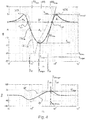
- Fig. 4 is a Bode plot showing two different sensitivity functions S and S' which characterize two possible active occlusion control configurations for a particular user.
- the thick curves refer to S, the thin ones to S'.
- the upper diagram shows the magnitudes expressed in decibels, namely
- S results from a first compensator filter dataset candidate C 1 scaled with a scaling factor g 1 .
- S' results from a second compensator filter dataset candidate C 2 scaled with a scaling factor g 2 .
- the sensitivities are calculated based on the same complex frequency-dependent plant transfer function P which may have been measured for a particular user as described above.
- S 1 1 + P ⁇ C 1 ⁇ g 1
- S ′ 1 1 + P ⁇ C 2 ⁇ g 2
- dB can be divided into three frequency ranges. In a first range below f min there is the low frequency overshoot LOS. In a second range between f min and f max there is the actual occlusion reduction. In a third range above f max is the high frequency overshoot HOS, which is typically at 1 to 3 kHz. Occlusion reduction in a particular frequency range is always accompanied by amplification below and above this range. This behavior is called waterbed effect. More formally it is called "Bode's integral theorem". A large LOS may result in an unpleasant perception of footfall sounds.
- a 1 between the f-axis and the LOS
- a 2 between the f-axis and negative section of the
- a 3 between the f-axis and the HOS.
- the sum of overshoot areas A 1 and A 3 is just as large as A 2 .
- the area A 2 is equal to an absolute value
- a 2 the stronger the occlusion reduction.
- f min and f max can be defined as bordering the frequency range where
- , f OE OEmax , f 1OE , f 2OE , OE RMS , VE,
- the parameter S max may be treated in a special way. S max should not exceed the upper bound S bound because otherwise the system may become unstable which results typically in a whistling in the frequency range of the HOS and/or or in a rumbling in the frequency range of the LOS. Therefore the scaling factor g, i.e. g 1 or g 2 , is preferably selected such that S max is below or at the bound S bound . The latter applies for the two curves shown in the Bode plot, i.e. g 1 is equal to a maximum scaling factor g 1max and g 2 is equal to a maximum scaling factor g 2max .
- the parameter S min may also be treated in a special way.
- S min is a good indicator for the strength of the active occlusion control.
- a threshold S thres may be used to assure a minimum strength.
- S min ⁇ S thres may have to apply.
- a target value S target may be defined for S min to specify a target strength.
- S min depends on g 1 .
- a target scaling factor g target can be defined as being the g 1 for which S min is equal or close to S target .
- the scaling factor g 1 of the curve shown in the Bode plot is smaller than g target . Accordingly S min is several decibels larger than S target .
- Scaling the compensator filter dataset candidate C 1 with g target would result in a S max above S bound .
- the system would show substantial artifacts and would not be substantially robust against destabilization any more.
- the compensator filter dataset C 1 * g target should never be used in the actual hearing aid. However, it may be used for applying selection criteria. If this results in C 1 being a preferred candidate, C 1 would be scaled with g max instead of g target before being employed and/or evaluated in the actual hearing aid.
- the parameter SS max indicates the maximum steepness of the magnitude curve
- the maximum steepness is typically in the frequency range towards the HOS. A large maximum steepness should be avoided because it may cause artifacts.
- S is defined such that a smaller magnitudes mean less occlusion.
- S could be just as well defined such that larger magnitudes mean less occlusion.
- S according to the alternative definition is the multiplicative inverse of S according the primary definition.
- S and formulas comprising S would have to be adapted accordingly.
- the additive inverse would have to be used, i.e. "
- the fitting device may be configured for providing various graphical information about the fitting process and the fitting result, for example Bode plots of complex functions, graphs of spectral functions and bar or pie charts of continuous parameters or ratings. Diagrams may show for example characteristics of P, C RAW , C, S, OE, VE, OM, F0 L , F0 Spectrum and ⁇ R 1 , R 2 , R 3 ... ⁇ , in particular in relation to each other and/or for different compensator filter datasets in the same diagram.
- the Bode plot of different S shown in Fig. 4 may be fully or partially displayed to the fitter.
- the subjective evaluation of dataset candidates ⁇ C A , C B , C C , ... ⁇ by the user may be fully or partially replaced by a graphical evaluation by the fitter.
- a benefit assessment is carried out at one or more stages of the method.
- the subjective benefit can be assessed, as already described above, by comparing one or more configurations having active occlusion control, such as configurations "A", "B” and "C", with a configuration " ⁇ " not having it.
- an automatic benefit assessment may be carried out to determine if a substantial benefit can be provided to the user 31 by the active occlusion control feature. If no substantial benefit can be provided the system outputs a corresponding message.
- the message can for example be an acoustic and/or visual message presented by the fitting device 12.
- One potential reason for insufficient benefit may be that the user has a relatively strong low frequency hearing loss such that he or she does not perceive occlusion sounds in the first place. Best candidates for occlusion control are individuals having mild hearing losses.
- the benefit assessment may comprise the step of analyzing the user's hearing loss or audiogram, in particular by checking if the hearing loss is less than 40 dB at a set of frequencies relevant for occlusion, in particular at 125 Hz, 250 Hz and/or 500 Hz.
- Further measures may be properties of the complex frequency-dependent plant transfer function P, of the objective frequency-dependent occlusion effect function OE or
- the feature is useless if there is no substantial or no occlusion effect in the first place, for example if the vent 10 is sufficiently large and if there is no need to reduce its size.
- the assessments are preferably carried out as soon as the necessary data becomes available, in particular directly after a corresponding acoustic measurement.
- Hearing loss data may be available before inserting the hearing aid for the first time, and in particular before selecting a hearing aid.
Description
- The invention relates to the field of fitting hearing aid devices. More particularly, it relates to a method for fitting a hearing aid device with active occlusion control to a user according to
claim 1. - A hearing aid device is a device for aiding an individual in regard to its hearing. It may be a hearing aid or hearing prosthesis for compensating a hearing loss of its user. It may also be a hearing protection device which helps individuals to hear without damage in noisy environments. Such a device may transmit speech and attenuate noise by selective amplification. The occlusion effect is an effect experienced by individuals when an ear canal is fully or partially closed by an occluding object. In such a condition, the own voice of the individual and other body conducted sounds are perceived by him- or herself unnaturally loud. The earpiece of a hearing aid device can be such an occluding object. Active occlusion control is a method for reducing the occlusion effect actively. Actively means by destructive interference, i.e. emitting a kind of anti-sound. A passive occlusion control (or passive occlusion reduction) would be the provision of a large vent. However, hearing aids with a large vent are prone to feedback and cannot deliver loud low-frequency sound due to leakage from the canal to the outside and cannot provide good sound cleaning due to leakage from the outside into the canal. Providing hearing protective devices with a large vent renders them useless because low-frequency noise can pass without substantial attenuation through the vent. Occlusion is not to be confused with ampclusion. Users of hearing aid devices may perceive their own voice as being unnatural due to its amplification by the hearing aid device. Ampclusion can be counteracted by reducing the hearing aid device amplification in the frequency range of the users voice. Both occlusion control and ampclusion control aim for providing an own voice perceived as more natural.
-
US 6,035,050 by Weinfurtner discloses a method for determining optimum parameter sets in a hearing aid. During an optimization phase an optimal user specific parameter set is allocated by selecting one of several trial parameter sets available. -
WO 2004 / 021740 A1 by Rasmussen et al. discloses a method for counteracting the occlusion effect of an electronic device like a hearing aid. Sound conditions in the cavity between the ear piece and the tympanic membrane are determined. The transmission characteristics of the transmission path to the receiver counteracts the occlusion effect. -
WO 2006 / 037156 A1 by Mejia et al. discloses an acoustically transparent occlusion reduction method. An electro-acoustic feedback network produces phase cancelling sounds in the ear. The integration with a hearing aid improves the user's perception of own voice. -
WO 2008 / 017326 A1 by Nordahn discloses a method for in-situ occlusion effect measurement. A hearing aid comprises a microphone for external sounds and a microphone for sounds in the occluded ear. An occlusion effect value is produced from the difference. The user may read a text passage or vocalize a sound such as /iii/ or /uuu/. The hearing aid may be fitted based on the occlusion effect value. -
US 2009 / 238387 by Arndt et al. discloses a method for actively reducing occlusion. A transducer transmission function, which is defined for the transmission path from the input of a receiver via the auditory canal to the output of a microphone, is subjected to an automatic plausibility check. -
US 2009 / 274314 by Arndt et al. discloses a method for determining a degree of closure in hearing devices. Arndt mentions active occlusion reduction. An effective vent diameter specifies the degree of closure. An interpretation of this value is easily possible by a hearing device acoustician. -
WO 2010/083888 A1 by Rung et al. discloses a method for in situ occlusion effect measurement. An external sound pressure of an occluded ear is measured by the microphone of a BTE hearing aid. The sound pressure at the eardrum is measured by a hearing aid receiver. -
WO 2012 / 003855 A1 by Rung discloses a method for measuring the occlusion effect of a hearing aid user. The diameter of a ventilation channel may be increased to reduce the occlusion effect. Leakage between bands is regarded in the measurement. -
US 2010/0002896 A1 relates a hearing aid including an adaptive occlusion reduction feature implemented by a compensation filter provided between the signal processing unit and the output transducer, wherein an occlusion reduction function may be determined at times when no occlusion signal is present, i.e. at times when the hearing aid user is not speaking. The occlusion reduction function is determined from a closed loop transfer function involving a ear canal microphone for picking up sound in the ear canal. - It is an object of the invention to provide a method for fitting active occlusion control means of a hearing aid device in an easy, precise, flexible, robust, sustainable, effective and/or efficient way. This is especially important because active occlusion control does not only reduce occlusion, but also has side effects. A first side effect is a possible instability of the occlusion control loop. A second side effect is the so called waterbed effect according to which there is not only suppression of occlusion sounds but also amplification of sounds at frequencies below and above the suppression. Hence, what is needed is a good trade-off between wanted and unwanted effects suitable for application in practice.
- The object is achieved by the method of
claim 1. Using a complex frequency-dependent plant transfer function and using an objective frequency-dependent occlusion effect function and/or at least one property of it for determining a compensator filter dataset has the advantage that it allows to adapt an active occlusion control means to the needs of a particular individual in an easy, precise and efficient way. The method ofclaim 1 is also advantageous in that actually measuring the objective frequency-dependent occlusion effect function and/or the at least one property of it and using a result of such a measuring for determining a compensator filter dataset allows to adapt active occlusion control means to the needs of a particular individual in an especially precise and efficient way. - The method of
claim 2 can be advantageous in that predefining compensator filter dataset candidates allows to apply audiological expertise prior to the actual fitting, hence a good fitting can be achieved later with less expertise. Candidates can be predefined with regard to the aspects stability and reliability. Selecting between discrete candidates can be easier, more precise, more efficient and less demanding for a fitter and/or a hearing aid device user than adjusting multiple continuous parameters or even curves. There is not even a need for awareness of the multitude of parameters actually applied. - The method of
claim 3 can be advantageous in that by scaling the compensator filter the effect of the filter, and thereby the occlusion control strength, can be adjusted in a precise and easy way. It opens up the possibility to provide a user friendly manual adjustability. Good tradeoffs between wanted and unwanted effects may be found. The occlusion control strength may also be maximized up to the bound given by system stability requirements. - The method of
claim 4 can be advantageous in that applying selection criteria to a set of compensator filter candidates allows to select a candidate fully automatically or to reduce the number of candidates to be tested by the user and/or the fitter thereby making the choice of an optimum candidate easier and faster. - The method of
claim 5 can be advantageous in that actually trying out the hearing aid with different configurations gives a very good indication which fitting is best in the perception of the user. Letting the user actively participate in the fitting improves the acceptance of its results by the user. - The method of
claim 6 can be advantageous in that calculating a quality indicator for each candidate by applying a criterion allows to identify a best or a subset of best candidates in a fast and reliable way. - The method of
claim 7 can be advantageous in that assigning weights to criteria allows to normalize the numeric quality indicators of different criteria and/or to regard multiple criteria without losing the focus on the criteria which are most significant. - The method of
claim 8 can be advantageous in that using a complex frequency-dependent vent effect and/or leakage function for determining a compensator filter dataset allows to adapt active occlusion control means to the needs of a particular individual in an especially precise, optimized and efficient way. - The method of
claim 9 can be advantageous in that using a fundamental frequency of a voice of the user for determining a compensator filter dataset allows to adapt active occlusion control means to the needs of a particular individual in an especially precise, optimized and efficient way. - The method of
claim 10 can be advantageous in that presenting a recorded real life sound stimulus is perceived by the user of the hearing aid as more pleasant than artificially generated stimuli. - The method of claim 11 can be advantageous in that determining properties of a sensitivity function and/or properties of a occlusion modification function for specific compensator filter candidates allows to compare the quality of such candidates in an objective and reliable way.
- Symbols such as "CA", "P", "|OE|" or "{C1, C2, C3...}" in the claims are to be regarded as reference signs if they are presented in parentheses and these parentheses are not part of a formula. Reference signs should not be seen as limiting the extent of the matter protected by the claims. Their sole function is to make the claims easier to understand.
- Further embodiments and advantages emerge from the claims and the description referring to the figures.
- Below, the invention is described in more detail by referring to the drawings showing exemplified embodiments.
-
Fig. 1 is a diagram of a hearing aid suited to be fitted by the fitting method of the invention; -
Fig. 2 is a flow diagram illustrating an embodiment of the fitting method of the invention; -
Fig. 3 is a diagram showing a hearing aid and a fitting device configured for carrying out the fitting method of the invention; -
Fig. 4 is a Bode plot showing two different complex sensitivity functions; - The described ambodiments are meant as examples and shall not confine the invention, which is defined in the appended claims.
-
Fig. 1 is ahearing aid 3 with active occlusion control suited to be fitted to a user by the fitting method of the invention. It has anoutside microphone 4 for sensing sound of an environment of the user. This sound is processed by sound cleaning and loss compensation means 5 configurable by a dataset H. As already indicated, the invention may also be applied for a hearing protection device which would have a similar diagram, just with the difference that there would be no hearing loss compensation. Thehearing aid 3 is arranged in anear canal 2 of the user. Between thehearing aid 3 and theeardrum 1 there is a residual canal space. Thereceiver 7 is configured for emitting sound into this residual canal space. Residual canal space and the outside are connected by avent 10. Thehearing aid 3 has means for active occlusion control comprising acanal microphone 8 configured for sensing a sound pressure in the residual canal space, an occlusioncontrol compensator filter 9 arranged in a feedback loop and configurable by a compensator filter dataset C and apre-equalizer 6 configurable by a dataset E arranged in a signal path from theoutside microphone 4 to thereceiver 7. The dataset E may be determined based on the compensator filter dataset C by the formula E=1 +P*C. - The term "canal microphone" in the present document is to be interpreted in a broad manner. It is meant to cover all transducers which are suitable for sensing a sound and/or vibration in the residual canal space, for example conventional microphones, but also optical microphones, acceleration sensors and/or strain gauges. The
canal microphone 8 may also be integrated or combined with thereceiver 7. Both transducers may simply share a common casing and/or wax protection system and be otherwise separate. However, it is also possible that the two transducers share the same membrane or even a common coil. It is also possible to sense the sound in the residual canal space by one or two vent microphones, the sound inlets of which are arranged in the wall of thevent 10. A directional vent microphone or two vent microphones combined with a special processing may allow to determine which sounds in thevent 10 originate from the residual canal space and not from the outside. Thecanal microphone 8 may also be combined, complemented and/or enhanced with various further sensors. -
Fig. 2 is a flow diagram illustrating an embodiment of the fitting method of the invention. In afirst step 41, the hearing aid device is inserted at least partially into the ear canal. A communication connection is established between the hearing aid device and a fitting device. The hearing aid device is switched into a fitting mode. In asecond step 42, a plant stimulus is generated and presented by the receiver. In athird step 43, a complex frequency-dependent plant transfer function P from an input of the receiver to an output of the canal microphone is measured by sensing a resulting sound in the ear canal and by analyzing the resulting sound in regard to the plant stimulus. In afourth step 44, a complex frequency-dependent vent effect and/or leakage function VE of an earpiece of the hearing aid device is derived from the frequency complex dependent plant transfer function P. In afifth step 45, the user's voice is activated and/or a bone conduction stimulus is presented. In asixth step 46, an objective frequency-dependent occlusion effect function OE is measured by sensing a canal sound in the ear canal, by obtaining a reference sound and by analyzing the canal sound in regard to the reference sound. The reference sound is the user's voice as an outside sound sensed by an outside microphone and/or the bone conduction stimulus. Strictly speaking, not sounds are analyzed but corresponding signals. In aseventh step 47, a fundamental frequency F0 of the voice of the user is determined from the canal sound and/or the outside sound. In aneighth step 48, a determination of a compensator filter dataset C is carried out by selecting a raw compensator filter dataset CRAW from a set of candidates {C1, C2, C3...} and by scaling it with a scaling factor g. In the selection process the data determined before is used, namely the complex frequency-dependent plant transfer function P, the complex objective frequency-dependent occlusion effect function OE, the frequency-dependent vent effect and/or leakage function VE and/or the fundamental frequency F0. In aninth step 49 the occlusion control compensator filter may be configured with the compensator filter dataset C. Optionally, if there is a pre-equalizer, it may be configured with a dataset E. The hearing aid device may then be switched from the fitting mode to the operation mode. - The sequence and comprehension of measurements and other steps of this flow diagram is purely exemplary and may be composed and varied in various ways. For example the occlusion effect measurement may be carried out before the plant measurement. Further, only a magnitude |OE| or a property of the complex objective frequency-dependent occlusion effect function OE may be determined and/or regarded. The frequency-dependent vent effect and/or leakage function VE may be left out completely or only a magnitude |VE| of it or a cutoff frequency fVE of it may be determined and/or regarded. The fundamental frequency F0 may also be left out completely, or instead a fundamental frequency range {F0min, F0max} may be determined and regarded.
- The method steps are presented in the claims in particular sequences. These sequences are exemplary and not mandatory, i.e. the claims are to be interpreted such that they cover also carrying out the same steps, but in other sequences, as far as it is feasible. In particular step B and C of
claim 1 may be interchanged. -
Fig. 3 shows a schematic representation of ahearing aid 3 and afitting device 12 configured for carrying out the fitting method of the invention. Thehearing aid 3 and thefitting device 12 are configured for communicating with each other. - The shown
hearing aid 3 is an ITE or in-the-ear hearing aid for compensating a hearing loss. As already indicated, the invention may also be applied for a hearing protection device such as a Serenity DP+ by Phonak™. The hearing aid device fitted according to the invention may also be a distributed or modular hearing aid device. Such a hearing aid device may have a behind-the-ear module as well as an in-the-ear module. The modules are generally electrically connected to each other. The in-the-ear module preferably comprises both thereceiver 7 and thecanal microphone 8. It is preferable to arrange both transducers in the canal because sound tubes to modules at other locations would introduce delays in the active occlusion control loop which would interfere with its proper functioning. The in-the-ear module may be a custom ear-piece or a one-size-fits-all dome. Thevent 10 in an earpiece of a modular hearing aid or in the main body of an ITE hearing aid has preferably a diameter in a range from 0.6 mm to 1.2 mm, in particular 0.8 mm or 1.0mm. Larger vents may cause feedback problems and impair sound cleaning features. Smaller vents may be prone to plugging and may not provide sufficient pressure equalization and moisture discharge. If the fitting method is carried out in regard to a plurality of users it is advantageous to use the same vent size each time and to accommodate personal preferences by the selection and scaling of the compensator filter dataset C. A hearing protection device has preferably no vent at all to provide maximum noise attenuation. Even though only onehearing aid 3 is shown a typical user will have two hearing aids. Each of them may be fitted as described in this document, in particular one after the other. However, certain steps may be carried out left and right simultaneously and/or in a synergic manner, as for example the measurement of the complex objective frequency-dependent occlusion effect function OE. The same stimulus presentation may be used for measurements at the left and the right hearing aid. Further, results from left and right may be compared for plausibility checks and/or may be combined for obtaining a higher precision. For example the signals of left and right outside microphones may be averaged or be selectively used depending on which signal is best. - The
fitting device 12 is represented inFig. 3 logically rather than physically. Blocks, such as the "plant measurement analysis means 18" are preferably not physical units, but instead algorithms or software stored in a memory of a computer. User controls such as the "strengthselector user control 33" may be graphical user interface elements on a display such as a slider operable by a mouse or touch screen. User controls may be provided for adjusting parameters and/or entering data such as g, gtarget, gmax, Sthres, Starget, Sbound, ftarget, f1S, f2S, tΦTarget, f1Φ, f2Φ, P, OE, |OE|, fOE=OEmax, f1OE, f2OE, OERMS, VE, |VE|, fVE, F0, F0min, F0max, {W1, W2, ...} and/or {R1, R2, R3...}. In generic terms, thefitting device 12 is preferably a device or system comprising a memory and a processor, wherein a fitting software is storable in the memory and executable by the processor. Typically thefitting device 12 would be a desktop personal computer or PC with a Microsoft Windows™ operating system and a fitting software, such as Target by Phonak™, communicating via a wireless interface such as Bluetooth™ with a fitting interface device such as NOAHLink™ by HIMSA or an iCube by Phonak™, which fitting interface device in turn communicates wirelessly or by electrical wires with one or twohearing aids 3. NOAHLink™ is normally worn like a medal on a neckband by the patient oruser 31. Instead of a desktop PC other computers may be used, such as laptop computers, notebook computers or tablet computers. Thefitting device 12 may be operated by a fitter 30, thehearing aid user 31 or by both of them. Typically, the fitter is an audiologist. However, it may also be a salesperson, an ENT-doctor, a general practitioner, a caretaker, a nurse, a teacher, a so-called "significant other" such as a relative or any competent individual. Finally, in the case of self-fitting, the fitter 30 may be thehearing aid user 31 him- or herself. If more than one individual is involved in the fitting, separate screens and input devices may be provided for them. Thefitting device 12 may also be smartphone, cellular phone and/or cordless phone. It may also be an assisted living device, which is a multifunctional device for supporting aged or handicapped people and may integrate functions such as an emergency alarm button, medical body parameter supervision and GPS tracking. It may further be a hearing aid remote control and/or it may be fully or partially integrated in thehearing aid 3, in particular in an earpiece or a behind-the-ear module of it. Thefitting device 12 may also be configured for remote or distance fitting. In this case at least part of thefitting device 12 is at a location remote from thehearing aid 3. For example, theuser 31 may be at his home, while the fitter 30 is in a call center or office, which may be in another building and/or several kilometers away. The fitting software and/or the fitting data may be fully or partially stored, processed and/or executed on a web server or in a cloud computing manner. - The system is configured for obtaining the complex frequency-dependent plant transfer function P based on a plant measurement and for using it in the determination of the compensator filter dataset C. The plant measurement is carried out with the hearing aid inserted (in-situ) and preferably, if there is a vent, with an open vent. Only if there is substantial environment noise it may be advantageous to close the vent. However, environment noise may also be dealt with by louder plant stimuli. The
user 31 is instructed to remain silent during the measurement. The measurement is similar to a feedback measurement. Hence, it may also be advantageously combined with it, in particular such that both measurements are carried out upon a single user or fitter action. The measurement may in particular be started by the fitter 30 by selecting the option "P" on amode selector control 32, which in turn may switch the system into a plant measurement mode. For the plant measurement, thereceiver 7 may be disconnected physically or logically from the hearing aid sound processing means 5, 6 and 9 and may be connected to asignal 28 provided by a plant stimulus generation and/or playback means 15. Different kinds of stimuli may be used, in particular artificially generated stimuli (AGS), recorded real life sound stimuli (RRS), current environment sound stimuli (CES) and/or stimuli generated based on sounds provided by an external device other than the fitting device 12 (EDS). Artificially generated stimuli may include broadband stimuli, such as pink noise and white noise, as well as tonal stimuli, such as stepped or swept sine or complex multi-sine stimuli. An example of a white noise stimulus is a PRBS stimulus (pseudorandom binary sequence) and in particular an MLS (maximum length sequence) stimulus. Recorded real-life stimuli may include music, nature sounds, such as sounds of a waterfall, voice or own voice of the user. Recorded real life stimuli are perceived by thehearing aid user 31 as being more pleasant and entertaining than artificially generated stimuli. The provision of recorded real life stimuli may be carried out by a hearing aid manufacturer and may comprise the steps of picking up environment sounds in the field with a microphone and storing them on a medium such as a hard disk. Recorded real life stimuli may be enhanced by combining them with other stimuli, in particular artificial ones. This allows for example to assure that all frequencies are sufficiently covered by the stimulus. Current environment sound may be used processed or unprocessed as stimulus. The external device may for example be a hi-fi system. Sounds may be transmitted and/or streamed from the external device to thehearing aid 3 by wire or wirelessly, either directly, or indirectly through thefitting device 12 and/or a streaming device such as an iCOM by Phonak™. The sounds may be used processed or unprocessed as stimuli. Finally the plant stimulus may be any result of filtering and/and combining of stimuli such as for example defined by
- Wherein α, β, γ and δ may be scalars and/or filters. Plant measurement analysis means 18 may calculate a difference of a logarithmic frequency domain representation of the resulting sound and a logarithmic frequency domain representation of the plant stimulus sound. Alternatively a quotient may be calculated of non-logarithmic representations of these sounds. A frequency analysis method may be used, in particular with tonal stimuli. A correlation method may be used, in particular with broadband stimuli. An adaptive algorithm, e.g. a LMS-algorithm (Least-Mean-Squares), may be used if there is no generated stimulus or if a processed or unprocessed environment sound is used as stimulus. More details about such calculations can be found in textbooks about "system identification". A plausibility check may be carried out for P, in particular for detecting if a wax protection system of
receiver 7 and/ormicrophone 8 is clogged. Preferably the complex frequency-dependent plant transfer function P is measured directly. However, it is also possible to measure only the magnitude |P| of the plant transfer function P and to estimate a phase function Φ = arg(P) e.g. by minimum phase considerations, Hilbert transformation and/or application of a sound propagation delay between receiver and microphone. "Complex" may be defined as "including phase information". It can be advantageous to subdivide the frequency range of the plant measurement, e.g. at 350 Hz, in order to have more low-frequency measurement points at a given FFT (fast Fourier transformation) size for better determining the low frequency overshoot described further down. The system is further configured for determining the compensator filter dataset C based on an objective frequency-dependent occlusion effect function and/or based on at least one property of it. The function may be a complex function OE or a magnitude function |OE|. The property may be a peak frequency fOE=OEmax at which the occlusion effect magnitude has its maximum or the relevant maximum. It may be also be a substantial occlusion effect frequency range {f1OE, f2OE} in which the occlusion effect is above a threshold and/or in which the occlusion effect is substantially at its maximum. It may also be a root mean square value OERMS of the objective frequency-dependent occlusion effect function. The property may refer to the full frequency range of OE. However, it may also refer to a certain part of the frequency range. - The objective frequency-dependent occlusion effect function and/or the at least one property of it is obtained based on a measurement while the voice of the
user 31 is active and while there are preferably no other outside sounds. Thehearing aid 3 is preferably muted, for example by switching off the receiver. The user's voice may be activated by instructing him or her to speak freely, read a text, repeat a word or sentence, ask a question, sweep a vowel and/or speak different vowels. The measurement may be started by the fitter 30 by selecting the option "OE" on amode selector control 32, which in turn switches the system into an occlusion measurement mode. The voice of the user may be picked up as a canal sound bycanal microphone 8 and as a reference sound by a reference microphone, for example theoutside microphone 4, an outside microphone of a further not shown hearing aid or any microphone connected to thefitting device 12. The corresponding signals 26 and 27 are transmitted to thefitting device 12. An open ear gain compensation "OEG" may be applied to the reference sound by compensation means 13 thereby obtaining a compensated outside sound. Alternatively, an inverse open ear gain compensation "1/OEG" may be applied to the canal sound by compensation means 14 thereby obtaining a compensated canal sound. Occlusion measurement analysis means 16 may calculate a difference of a logarithmic frequency domain representation of the canal sound or, as the case may be, the compensated canal sound and a logarithmic frequency domain representation of the reference sound or, as the case may be, the compensated reference sound. Alternatively a quotient may be calculated of non-logarithmic representations of these sounds. If no OEG compensation has been applied yet, it may still be applied to the resulting difference or quotient, or it may not be applied at all since an OEG is usually not much different from 0 dB in the relevant frequency range below 1 kHz. - Instead of activating and measuring the user's voice, an artificial own voice stimulus may be applied in an occlusion effect measurement. The body of the user may be vibrated by vibrating means. Such means may comprise a body stimulus generator and, connected to it, an electromechanical transducer such as a bone conduction headset. A canal sound resulting from such a vibration in the occluded ear canal is picked up by the
canal microphone 8. The signal of theoutside microphone 4 is ignored. Instead the signal of the body stimulus generator is used as reference sound. In the further processing the sound in the open ear canal can be estimated by applying a compensation to the reference sound similar to the OEG compensation described above. Accordingly, instead, an inverse compensation may be applied to the canal sound or no compensation may be applied at all. Since the vibration stimulus is reproducible, in contrast to the user's voice, a second, subsequent measurement may be carried out with a probe tube in the canal and without hearingaid 3, thereby obtaining a more precise open ear canal sound as reference sound which needs no compensation. Since the probe tube is already in place, the occluded canal sound may be also measured with the probe tube instead of thecanal microphone 8. - In embodiments with a
vent 10, the objective frequency-dependent occlusion effect function and/or the at least one property of it may refer to the occlusion with open or closed vent. Hence, in the strict sense OE is either OEVented or OEUnvented. The same applies accordingly for |OE| and the properties of OE. In many cases it is irrelevant which OE is regarded. OEVented is typically only in the low frequencies affected by the vent effect. In a particular embodiment primarily OEVented is used, and is, if necessary derived from OEUnvented by adding the vent effect. For measuring OEUnvented the vent may be temporarily closed. - As an example not covered by the invention, the objective frequency-dependent occlusion effect function and/or the at least one property of it may further be obtained by an estimation based on personal and/or hearing aid device data, in particular the size of a residual space between the earpiece of the
hearing aid 3 and theeardrum 1, a middle ear compliance and/or an effective leakage. The residual space depends on the penetration depth of the hearing aid earpiece and the ear canal geometry, which can be determined by an impression or scan. The middle ear compliance may be measured by tympanometry. The effective leakage may depend on the weight and/or material of the hearing aid earpiece. If there is no vent, the effective leakage may be determined based on a real ear occluded gain (REOG) measurement. Finally, in a simplified embodiment one average objective frequency-dependent occlusion effect function may be stored in thefitting device 12 and may be used for all fittings. - The system may also be configured for determining the compensator filter dataset C based on a frequency-dependent vent effect and/or leakage function of an earpiece of the
hearing aid 3. The function may be specified by a complex function VE, a magnitude function |VE| or simply by a cutoff frequency fVE of a high-pass filter approximation of such a function. The vent effect information can be manually entered. It can also be measured. It can further be derived from the complex frequency-dependent plant transfer function P, in particular by analyzing a roll-off of the complex frequency-dependent plant transfer function P and/or by applying a low-frequency fitting method of a filter, e.g. 2nd order, in regard to the complex frequency-dependent plant transfer function P. The derivation may be carried out by vent effect and/or leakage derivation means 19. Vent effect is caused by the penetration of sound through thevent 10. Leakage occurs when thehearing aid 3 does not exactly fit theear canal 2, for example because it is not correctly positioned or the canal has changed since the ear impression for manufacturing the earpiece was taken. Vent effect and leakage may be added to each other for defining a so called "effective vent". The vent effect and/or leakage function may therefore also be called "effective vent function". - The system may also be configured for determining the compensator filter dataset C based on a fundamental frequency F0, a fundamental frequency range {F0min, F0max} and/or a fundamental spectrum F0Spectrum of the voice of the
user 31. This information can be manually entered. It can also be estimated based on data relating to gender and/or age of theuser 31. F0 of males is about 125 Hz, F0 of females about 250 Hz and F0 of children about 440 Hz. F0 and the range {F0min, F0max} can further be measured by sensing the voice of the user byoutside microphone 4 and/orcanal microphone 8. Thehearing aid 3 is preferably muted during the measurement. The measurement can be carried out together with the measurement of the objective frequency-dependent occlusion effect function or properties of it, i.e. the same recorded sound data is used for both, determining F0 and/or the range {F0min, F0max} and determining OE, |OE|, fOE=OEmax, the range {f1OE, f2OE} and/or OERMS. The determination of F0 and the range {F0min, F0max} may be carried out by voice measurement analysis means 17. For measuring the range {F0min, F0max} the user may be instructed to speak in pitch and/or loudness varying way, for example a German speaking user may be instructed to ask a question, at the end of which the pitch is generally higher. F0 and the range {F0min, F0max} may also be acquired in a loudness dependent manner, for example by acquiring the values F0soft, F0mid and F0loud or by acquiring a level dependent function F0L(LdB), wherein LdB is a loudness level in decibels or a loudness level class index. F0 is typically higher for louder voice. In a particular embodiment the range {F0min, F0max} is defined such that it accommodates F0soft, F0mid and optionally F0loud. - The above mentioned measurements are preferably carried out during a fitting session, while there is a data connection between the
fitting device 12 and thehearing aid 3 and while theuser 31 is in a fitting room or a soundproof both. However, it is also possible that these measurements are carried out in the field, during normal use of thehearing aid 3, at particular times, temporarily and/or in fully continuous manner. A sound situation analysis means may determine which parameter can be measured in a particular situation. For example OE and F0 may be measured in quiet environments, while the user is speaking loudly. P may be measured while theuser 31 is quiet, the environment is quiet and loud sounds are presented to him or her by thehearing aid 3, as for example when sounds are streamed from a television with muted loudspeakers. Such measurement results may be used instantaneously for automatically readjusting the compensator filter dataset C in the field. However, they may also be stored in thehearing aid 3 for a later, more controlled use during a fitting session. Accordingly, thefitting device 12 may be configured for reading out such measurement results from thehearing aid 3. - The
fitting device 12 may comprise adatabase 22 with a set of raw compensator filter dataset candidates {C1, C2, C3...}. Raw compensator filter dataset candidates may be represented in different ways as described further below. The term "raw" is used because the datasets are usually further processed and in particular scaled before they are applied in thefilter 9 as also described further below. However, the term "raw" in this document is not meant to imply that there must be further processing. In addition, the raw datasets may be a result of a preprocessing, hence they may be only "raw" in respect to a certain stage of the fitting method. The raw candidates may in particular have peak magnitude of 0 dB, which guarantees stability if they are applied unprocessed. The set of candidates is generic in that it is not defined for a particular user. The set of candidates is preferably predefined, for example by a hearing aid manufacturer and/or fitting software provider. It may be distributed together with a fitting software or separately, for example on a compact disk or over the internet. Typically the database remains unchanged after the fitting software has been installed or updated and in particular after the fitting in regard to a particular user has started. The set may comprise one or more candidates. For implementing the concept of choosing between candidates a set of two candidates is sufficient. A reasonable number of candidates may be about fifty. However, memory and processing power of a standard computer may allow thousands or millions of candidates. Therefore it is possible to provide candidates even for very rare user profiles. The predefinition of candidates may be based on statistical and/or empirical data. Hypothetical or real fittings or compensator filter datasets may be determined for typical hearing aid device and user profiles and may be evaluated based on criteria as described further below in regard to the candidate selection. The predefinition of candidates may also comprise the steps of providing a set of base filters {CB1, CB2, CB3...} and a set of modification filters {CM1, CM2, CM3...}. Each base filter can then be combined with each subset of modification filters to determine a candidate. For example candidates may be defined as follows:
- Such combinations may be calculated in advance and be provided with the fitting software. However, they may also be calculated at runtime. There may also be separate sets of dataset candidates for different user groups, such as for children, females and males. A lookup table may be used to link user groups with sets.
- The
fitting device 12 may comprise a candidate selection means 24. In a particular embodiment such a selection may result directly in a compensator filter dataset C for use in thehearing aid 3. However, in a preferred embodiment a preferred raw compensator filter dataset CRAW or set of preferred raw compensator dataset candidates {CA, CB, CC, ...} is obtained by choosing candidates from the set of raw compensator filter dataset candidates {C1, C2, C3...}. - The preferred candidate or candidates are preferably chosen taking into account the complex frequency-dependent plant transfer function P, the objective frequency-dependent occlusion effect function and/or the at least one property of it, i.e. OE, |OE|, fOE=OEmax, {f1OE, f2OE} and/or OERMS, and optionally the frequency-dependent vent effect and/or leakage function VE, |VE| or a cutoff frequency fVE of a high-pass filter approximation of such a function, as well as the fundamental frequency F0 and/or fundamental frequency range {F0min, F0max}.
- The quality of a candidate is preferably assessed by applying a selection criterion K or a set of selection criteria {K1, K2, ...}. The criterion or at least one criterion of the set of criteria is preferably a property of - or is based on one or more properties of - a complex frequency-dependent candidate specific sensitivity function S and/or a complex frequency-dependent candidate specific occlusion modification function OM. S may be defined by

Fig. 4 further down. OM may be defined by
- The provisional scaling factor gprov is provisional in that it is only used for applying the selection criteria, i.e. used for calculating certain values as shown in the criteria table below. It is a purely theoretical value and is not necessarily applied in the
actual hearing aid 3. It must therefore not fulfill stability criteria. There are amongst others the following nonexclusive options: - The provisional scaling factor gprov may be set to a maximum value gmax at which the system is just still stable. This has the advantage that the criteria are applied based on a scaling factor g which can later be used in the
actual hearing aid 3. The determination of gmax is described further down. - The provisional scaling factor gprov may be set to a target value gtarget which may be derived from a target minimum occlusion modification OMtarget or a target minimum sensitivity Starget (See also
Fig. 4 ). Oftentimes such targets cannot be reached due to stability issues. Hence, the scaling factor g used for configuring theactual hearing aid 3 will typically be smaller than gtarget and will be in particular be gmax. The determination of gtarget can be carried out in a similar manner as the determination of gmax described further down; - The provisional scaling factor gprov may be set to 1, thereby effectively eliminating gprov from the above formulas. In this case the
database 22 may advantageously contain already scaled compensator filter datasets, and in particular differently scaled compensator filter datasets, for different typical plant characteristics; - The provisional scaling factor gprov may be set to the scaling factor g which is later used in the
actual hearing aid 3. It would thereby be, in fact, not a provisional value anymore; - The provisional scaling factor gprov may be set to a manually selected value, in particular a value selected by the fitter 30 and/or the
user 31. - The following table contains examples of selection criteria:
Symbol Description / Formula(s) / Quality / Parameter Smin Minimum sensitivity magnitude Smin = min(|S1|,...,|S N |) Small values and values below Sthres indicate good quality; Values matching well Starget indicate good quality. Sk is a sensitivity at frequency with index k; N is the highest index; Sthres is a threshold, in particular -20 dB or in a range {-10, -30} dB; Starget is a target minimum sensitivity. |ΔS| Absolute value of a difference between Smin and Starget |ΔS| - |Smin - Starget | Small values indicate good quality; See also parameters of Smin above Smax Maximum sensitivity magnitude Smax = max(|S 1|,...,|SN |) Values above Sbound may cause substantial artifacts and poor robustness against destabilization. Sk is a sensitivity at frequency with index k; N is the highest index; Sbound is in particular in the range of 4 to 6 dB, or about 5dB. Sint Integral over sensitivity magnitude, wherein both magnitude and frequency are regarded in a perceptive manner, in particular logarithmically, such that more weight is given to low frequencies. This criterion has the advantage that VE needs not to be regarded. It provides the same result as an integral over OM since the VE comprised in OM adds the same amount of area for each candidate. 
Small values indicated good quality. {fmin, fmax} is a substantial frequency range in which |S|dB < 0 dB. Savg Average of magnitude of S at two or more frequencies 
Small values at frequencies relevant for occlusion control indicate good quality. Sk is a sensitivity at frequency with index k; Navg is the highest index; A preferred set of frequencies is {125 Hz, 250 Hz, 500 Hz} or {100 Hz, 125 Hz, 160 Hz, 200 Hz, 250 Hz, 315 Hz, 400 Hz, 500 Hz} Ssum Sum of magnitude of S at two or more frequencies 
Small values at occlusion frequencies relevant for occlusion control indicate good quality. Sk is a sensitivity at frequency with index k; Nsum is the highest index; See also parameters of Savg above Φ max Maximum sensitivity phase Φ max = max(Φ1,...,Φ N ) 
Small values indicated good quality. Φk is a phase at frequency with index k; Sk is a sensitivity at frequency with index k; N is the highest index. SSmax Maximum sensitivity steepness 
Small values indicate good quality; Values below a threshold of 20 dB per decade indicate good quality. dS/df is a derivative of sensitivity S with respect to frequency f. Δf Bandwidth of a substantial frequency range in which |S|dB < 0 dB Δf = fmax - fmin Large values indicated good quality. |S|dB is a magnitude of S represented in decibels; fmin, fmax are bounds of said substantial frequency range. f S=Smin Frequency at which a magnitude of the sensitivity S has its minimum |S(fS=Smin )| = Smin Values matching well F0 or ftarget indicate good quality; Values fitting into {F0min, F0max} indicate good quality; Values fitting into {f1S, f2S} indicate good quality; Values matching well a function fx(fVE) indicate good quality; Values matching well a product x * fVE indicate good quality. F0 is a fundamental frequency of a voice of the user; {F0min, F0max} is a fundamental frequency range of the voice; ftarget is target frequency, in particular 200 Hz; {f1S, f2S} is a target frequency range, in particular 80 to 500 Hz; fx(.) is a function depending on fVE, for example fx(fVE) = 0.8 * fVE; fVE is a cutoff frequency fVE of a high-pass filter approximation of a frequency-dependent vent effect and/or leakage function VE; x is a factor, in particular 60 to 100%, in particular ca. 80%; Examples of ftarget, f1S and f2S are shown in Fig. 4 .fΦ=Φmax Frequency at which the phase Φ of the sensitivity S has its maximum Φ(fΦ=Φmax ) = arg(S(fΦ=Φmax )) = Φ max Values matching well fΦTarget indicate good quality; Values fitting into {f1Φ, f2Φ} indicate good quality. fΦTarget is a target frequency, in particular 800 Hz; {f1Φ, f2Φ} is a target frequency range, in particular 500 to 1000 Hz; Examples of fΦTarget, f1Φ and f2Φ are shown in Fig. 4 .1/OE Inverse of the function OE 1/OE OE = OEvanted OE = OEunvented ∗ VE A sensitivity function S matching well 1/OE indicates good quality. OEvented is the objective complex frequency-dependent occlusion effect function measured with open vent. fOE=OEmax Peak frequency of the magnitude of OE |OE(fOE=OEmax )| = OEmax OEmax = max(|OE 1|,...,|OEN |) The above fS=Smin matching well fOE=OEmax indicates good quality. OEk is a value of OE at particular frequency with index k; N is the highest index; OE is the objective complex frequency-dependent occlusion effect function. 
Peak frequency range of the magnitude of OE, substantial occlusion effect frequency range in which a magnitude of OE is above OEthres and/or in which a magnitude of OE is substantially OEmax |OE(f 1 OE...f 2OE )| ≈ OEmax OEmax = max(|OE 1|,...,|OEN |) |OE(f 1 OE...f 2OE )| > OEthres {fmin, fmax} matching well {f1OE, f2OE} indicates good quality; OEk is a value of OE at particular frequency with index k; N is the highest index; OEthres is a threshold; {fmin, fmax} is a substantial frequency range in which |S|dB < 0; OE is the objective complex frequency-dependent occlusion effect function. OERMS Root mean square value of OE 
SRMS matching well OERMS indicates good quality. OEk is a value of OE at particular frequency with index k; Sk is a sensitivity at frequency with index k; N is the highest index; OE is the objective complex frequency-dependent occlusion effect function. OMmin Minimum of the OM OMmin = max(|OM 1|,...,|OMN |) |OM| =| VE| dB + |S| dB OM = VE ∗ S Small values indicated good quality; Values below OMthres indicate good quality. OMk is a value of OE at a particular frequency with index k; N is the highest index; |OM| is the frequency-dependent magnitude of OM; |VE|dB is a frequency-dependent magnitude of VE expressed in dB; |S|dB is a frequency-dependent magnitude of S expressed in dB; VE is a complex representation of the frequency-dependent vent effect and/or leakage function. It is the same for all candidates; OMthres is a threshold of about -20 dB or of about -10 to -30 dB; OM is the complex frequency-dependent occlusion modification function. OMavg Average of magnitude of OM at two or more frequencies 
Small values at occlusion frequencies indicate good quality. See parameters of Savg and OMmin above. - In the specification of the criteria the expression "matching well" is used for describing the relation between a first and a second measure. If both measures are scalars, e.g. decibel values or frequencies, "matching well" means that the absolute value of their difference is small. If both measures are frequency ranges "matching well" means that the lower and upper bounds match well. If both measures are functions "matching well" may in particular mean that an application of the method of least squares indicates a good matching of the two functions.
- When carrying out the task of determining one preferred candidate CRAW or a set of preferred candidates {CA, CB, CC, ...} by applying a criterion K and by choosing from the available compensator filter dataset candidates {C1, C2, C3...}, a quality indicator may be calculated for each candidate thereby obtaining a set of quality indicators {Q1, Q2, Q3...}. A quality indicator may be a numeric representation of a property defined by a criterion K. Depending on the property small or large values may indicated good quality. It may also be a category such as "poor", "average", "good" or the like. The quality indicator Q1 for a candidate C1 and a criterion K, namely "Smallness of Smin", may be defined by:

- The function fQ(.) allows to derive quality indicators for properties which reflect not directly an extent of quality, for example if values in a certain range indicate good quality. It also allows to normalize the quality indicators of different criteria, for example if one property is a decibel value and another property is a Hertz value. The important feature of the quality indicator is that it provides a basis for comparing the quality of candidates. The following table shows an example:
K Rank C1 Q1 = 0.823 2 C2 Q2 = 0.945 1 C3 Q3 = 0.364 3 - The preferred raw compensator filter dataset candidate CRAW according to the example would be C2. A set of two preferred raw compensator filter dataset candidates {CA, CB} according to the example would be {C1, C2}.
- As already indicated above, not only one criterion K may be applied, but instead a set of criteria {K1, K2, ...}. In this case a weighting may be provided for each criterion of the set of criteria thereby obtaining a set of weights {W1, W2, ...}. The weights allow to regard certain criteria more than others. The following table shows an example with three raw compensator filter dataset candidates and three weighted criteria:
K1 K2 K3 K1,2,3 Rank Eval Weight W1 = 100 W2 = 0.5 W3 = 1 C1 QC1K1 QC1K2 QC1K3 Q1 = 0.773 3 R1 C2 QC2K1 QC2K2 QC2K3 Q2 = 0.248 1 R2 C3 QC3K1 QC3K2 QC3K3 Q3 = 0.334 2 R3 - Multi-criteria quality indicators Q1, Q2 and Q3 are calculated for the candidates C1, C2 and C3. The multi-criteria quality indicator QY for a particular Yth candidate CY is determined by first calculating criterion-specific quality indicators QCYK1, QCYK2 and QCYK3 for the selection criteria K1, K2, and K3 and then combining these criterion-specific quality indicators in a weighted manner by applying a weighting function fW(.):

- In a preferred embodiment the weighting function is linear and applies a weighting factor to each criterion-specific quality indicator, as shown by the following formula:

- However, the weighting function fW(.) may also be a polynomial and in particular comprise quadratic terms as shown by the following example:

- The set of weights {W1, W2, ...} for the set of selection criteria {K1, K2, ...} can be obtained by carrying out a subjective evaluation of each candidate of the set of raw compensator filter dataset candidates {C1, C2, C3...} by one or more individuals thereby obtaining a set of subjective evaluation results {R1, R2, R3...}. The evaluation may in particular be carried out based on a scaling to a maximum stable active occlusion control strength and/or based on an adjustable scaling. The weights {W1, W2, ...} are then set such that a set of multi-criteria quality indicators {Q1, Q2, Q3...} calculated based on the set of weights {W1, W2, ...} substantially best matches the set of subjective evaluation parameters {R1, R2, R3...}. This may comprise carrying out a regression analysis, a stepwise regression analysis, a discriminant analysis and/or a stepwise discriminant analysis.
- As already indicated, the compensator filter datasets {C1, C2, C3...} stored in
database 22 are "raw". Before they are actually applied as occlusion filter dataset C thehearing aid 3 they are scaled by a scaling factor g:
- The scaling factor g influences the strength of the occlusion control. However, if g is chosen too large, the active occlusion control loop may become unstable. Accordingly, there is a maximum allowable scaling factor gmax. This value depends on the raw compensator filter data set such as CRAW or CA and on the complex frequency-dependent plant transfer function P of the particular individual and should therefore be recalculated if any of these parameters changes. In a preferred embodiment g is not manually adjustable but always set to gmax such that the occlusion control is maximized while keeping the system stable. In another embodiment the scaling factor g and therefore the strength of the occlusion control is adjustable manually by the fitter 30 and/or the
user 31, in particular by the strengthselector user control 33. The adjustment range is preferably limited such that gmax cannot be exceeded. Further, the g may have a particular initial value g0, which can for example be gmax. - The active occlusion control loop is stable and substantially robust against destabilization if the maximum sensitivity Smax does not exceed a predefined value Sbound. The stability of a system with feedback can be assessed based on a Nyquist plot. A distance between the Nyquist plot and the Nyquist point at (-1, i * 0) is a stability criterion. The maximum sensitivity Smax is an indicator for this distance and therefor also a stability criterion. The smaller Smax, the more robust is the system against destabilization. Sbound is typically in the range from 4 to 6 dB, in particular at 5 dB. Preferably the system allows to redefine Sbound, since empirical tests may imply other values. gmax may be calculated based on CRAW, P, Sbound and the following equations:

- However, since there is no formula for a direct calculation of gmax it may be advantageous to determine gmax by an iterative method. For example g might be increased in one dB-steps and after each increase Smax is calculated and evaluated.
- In a particular implementation of the candidate selection means 24 the user and hearing aid specific data such as P, OE, |OE|, VE, |VE|, fVE, F0, F0min, F0max, age, gender, hearing loss, hearing aid coupling and hearing aid type is mapped to a finite number of categories. The preferred raw compensator filter dataset CRAW or the set of preferred raw compensator dataset candidates {CA, CB, CC, ...} is then determined without actually calculating criterion data such as Smin. Instead the candidate or candidates for the determined category are looked up in a lookup table. The lookup table may also be combined with a criterion based evaluation. Both, lookup table and criterion based evaluation may be used in an arbitrary sequence to reduce the number of candidates until a target number of candidates has been reached.
- As already indicated the candidate selection means 24 may not only provide a preferred raw compensator filter dataset CRAW but instead also a set of preferred raw compensator dataset candidates {CA, CB, CC, ...} which is a subset of the set {C1, C2, C3...} stored in the database. The
hearing aid 3 is then temporarily and successively configured based on candidates of this subset. Such a demonstration of candidates may be started by the fitter 30 by selecting the option "ABC" on amode selector 32, which in turn switches the system into a demonstration mode. In a first trial the compensator filter C may be configured with CA * gA, in a second trial with CB * gB and so forth. A particular candidate may also be demonstrated differently scaled. There may be presentations CA * gA1 and CA * gA2. An additional configuration to be evaluated may be "No AOC", i.e. without active occlusion control. At least two configurations should be presented, wherein one might be the "No AOC" configuration. However, optimally three to five configurations are presented. Theuser 31 may be instructed to speak, walk, chew, listen to the fitter 30 speaking or listen to a surround sound system. Theuser 31 and/or the fitter 30 may actively switch between the configurations by actuating a candidateselector user control 34 or the configurations may be presented automatically one after the other for a certain time and/or until a corresponding evaluation result is entered. Eventually, thefitting device 12 obtains an absolute or relative evaluation information in regard to one or more of the demonstrated configurations from theuser 31. Theuser 31 and/or the fitter 30 may enter such information, in particular by a candidaterating user control 35. Based on the information the system determines which of the candidates CA, CB, CC is the preferred candidate. The result CRAW or the scaled result CRAW * g is then stored in the non-volatile memory of thehearing aid 3, in particular by selecting the option "NVM" on amode selector control 32. The hearing aid may be then or thereby switched from the fitting mode back to the operation mode. - The compensator filter dataset C may also be determined without the above mentioned candidates, in particular by a calculation based on the equations:


- The fitting method of according to the invention may also be used to determine more than one compensator filter data set, for example for different hearing programs or hearing situations such as a CSp for speech, a CSpN speech in noise, a CC for calm situations and a CM for music or for different loudness levels such as a CS for soft, a CM for medium and a CL for loud. Accordingly, more than one compensator filter data set may be stored in the non-volatile memory of the
hearing aid 3. - Once a compensator filter dataset C has been determined the occlusion
control compensator filter 9 and thepre-equalizer 6 may be configured based on it, such that it becomes part of an active configuration of the signal processor of thehearing aid 3. This may in particular occur during the above mentioned demonstrations, at the end of the fitting session, when the hearing aid is switched on or to another program, when filter data is transmitted by asignal 29 from thefitting device 12 to thehearing aid 3 and/or when filter data is read from the non-volatile memory of thehearing aid 3. - The compensator filter datasets, such as C, CRAW, C1, C2, C3, CA, CB, CC, CSp, CSpN, CC, CM, CS, CM and CL, may be represented in two substantially different ways:
- A first way is named here "coefficient format". It is a representation as a set of scalar filter coefficients. The filter is preferably time-discrete. Such a set may comprise or consist of coefficients of a numerator polynomial in z, for example {b0, b1, b2, ...}, and coefficients of a denominator polynomial in z, for example {a1, a2, ...}. A simple implementation would be a "digital biquad filter". The coefficients may define a filter of nth order. A representation of C in this format is indicated below by the symbol C[cf].
- A second way is named here "function format". It is a representation as a complex frequency-dependent filter function, also referred to as frequency response. Such a function is preferably frequency discrete such that the function can be described by a complex vector of a predefined dimension. A reasonable tradeoff between accuracy and data size can be achieved by a third octave frequency resolution. A higher resolution function may be filtered to obtain a function having such a resolution. Preferably, the frequency resolution applied in measurements, calculations and/or filter definitions is the same. Accordingly, the complex frequency-dependent functions P, OE, OM, VE, S and C have preferably the same frequency resolution and the corresponding vectors have the same dimension. A representation of C in this format is indicated below by the symbol C[ff].
- The "coefficient format" has the advantage that it needs less memory and transmission time than the "function format". "coefficient format" data may be compressed and/or reduced to a data size of about 75 bytes, i.e. less than 100 bytes, per compensator filter dataset C. The "coefficient format" can easily be converted to the "function format". Vice versa, it is difficult and not very practical to convert the "function format" to the "coefficient format". The "function format" is much better suited for assessing the filter quality. The formulas comprising "C" in the present document, such as S=1/(1+P*C) are normally calculated based on the "function format". An exception is the scaling of a "raw" filter compensator filter dataset with a scaling factor, such as C=CRAW*g, and the additive inversion, such as C' = -C, which can be calculated well in both formats.
- In the following it is indicated which format is preferably used in which stage of the fitting process:
- The predefinition of raw compensator filter dataset candidates {C1, C2, C3...} is preferably at least partially carried out based on the "function format", because the predefinition involves most likely filter quality assessments.
- The storing of raw compensator filter dataset candidates {C1, C2, C3...} in the
database 22 is preferably carried out based on the "coefficient format" because of memory and convertibility considerations. However, the candidates may be stored additionally in the "function format". This allows to save processing time during the fitting session, because it eliminates the format conversion step. - The quality assessment and candidate selection by the
fitting device 12 is preferably carried out based on the "function format". - The transmission to the
hearing aid 3 as well as the signal processing within thehearing aid 3 as well as the storing in the non-volatile memory of thehearing aid 3 is preferably carried out based on the "coefficient format" because of data size considerations and its suitability as a basis for signal processing. - In the candidate selection process, it may be determined that a particular compensator filter dataset C[ff] is a good filter candidate and should be applied as C[cf] in the
hearing aid 3. Since it is not practical to calculate C[cf] directly from C[ff] a kind of backtracking is carried out. It is determined which CRAW[cf] and which g compensator filter dataset C[ff] is based on. C[cf] is then calculated based on the equation C[cf] = CRAW[cf] * g. -
Fig. 4 is a Bode plot showing two different sensitivity functions S and S' which characterize two possible active occlusion control configurations for a particular user. The thick curves refer to S, the thin ones to S'. The upper diagram shows the magnitudes expressed in decibels, namely |S|dB and |S'|dB. The lower diagram shows the phases, namely Φ = arg(S) and Φ' = arg(S'). S results from a first compensator filter dataset candidate C1 scaled with a scaling factor g1. S' results from a second compensator filter dataset candidate C2 scaled with a scaling factor g2. The sensitivities are calculated based on the same complex frequency-dependent plant transfer function P which may have been measured for a particular user as described above.
- The magnitude function |S|dB can be divided into three frequency ranges. In a first range below fmin there is the low frequency overshoot LOS. In a second range between fmin and fmax there is the actual occlusion reduction. In a third range above fmax is the high frequency overshoot HOS, which is typically at 1 to 3 kHz. Occlusion reduction in a particular frequency range is always accompanied by amplification below and above this range. This behavior is called waterbed effect. More formally it is called "Bode's integral theorem". A large LOS may result in an unpleasant perception of footfall sounds. There is an area A1 between the f-axis and the LOS, an area A2 between the f-axis and negative section of the |S|dB-curve and an area A3 between the f-axis and the HOS. The sum of overshoot areas A1 and A3 is just as large as A2. The area A2 is equal to an absolute value |Sint| of the above defined Sint. The larger A2, the stronger the occlusion reduction. fmin and fmax can be defined as bordering the frequency range where |S|dB is below 0 dB. However, it is to be noted that |S|dB may also be smaller than 0dB in small or negligible frequency ranges below and above the primary occlusion reduction frequency range. The range between fmin and above fmax may therefore be referred to as the "substantial frequency range where |S|dB is below 0 dB".
- For estimating the quality of a particular sensitivity S, as already indicated above, the various properties of S, and in particular of |S|, may be regarded, for example the shown Smin, Smax, SSmax, Δf, fmin, fmax, fS=Smin, A2, Φmax and fΦ=Φmax and the not shown Sint and SRMS, in particular in relation to further values such as the shown Sthres, Starget, Sbound, ftarget, f1S, f2S, fΦTarget, f1Φ, f2Φ, F0, F0min and F0max and the not shown OE, |OE|, fOE=OEmax, f1OE, f2OE, OERMS, VE, |VE| and fVE.
- The parameter Smax may be treated in a special way. Smax should not exceed the upper bound Sbound because otherwise the system may become unstable which results typically in a whistling in the frequency range of the HOS and/or or in a rumbling in the frequency range of the LOS. Therefore the scaling factor g, i.e. g1 or g2, is preferably selected such that Smax is below or at the bound Sbound. The latter applies for the two curves shown in the Bode plot, i.e. g1 is equal to a maximum scaling factor g1max and g2 is equal to a maximum scaling factor g2max.
- The parameter Smin may also be treated in a special way. Smin is a good indicator for the strength of the active occlusion control. A threshold Sthres may be used to assure a minimum strength. For rendering a compensator filter dataset "preferred" Smin < Sthres may have to apply. Further, a target value Starget may be defined for Smin to specify a target strength. Smin depends on g1. A target scaling factor gtarget can be defined as being the g1 for which Smin is equal or close to Starget. The scaling factor g1 of the curve shown in the Bode plot is smaller than gtarget. Accordingly Smin is several decibels larger than Starget. Scaling the compensator filter dataset candidate C1 with gtarget would result in a Smax above Sbound. The system would show substantial artifacts and would not be substantially robust against destabilization any more. Therefor the compensator filter dataset C1 * gtarget should never be used in the actual hearing aid. However, it may be used for applying selection criteria. If this results in C1 being a preferred candidate, C1 would be scaled with gmax instead of gtarget before being employed and/or evaluated in the actual hearing aid.
- The parameter SSmax indicates the maximum steepness of the magnitude curve |S|dB. The maximum steepness is typically in the frequency range towards the HOS. A large maximum steepness should be avoided because it may cause artifacts.
- It is to be noted that within this document C is defined such that the filter must be configured with "-C", i.e. with C having a negative sign, as shown in
Fig. 1 andFig. 3 ). However, C could be just as well defined such that the filter must be directly configured with "C". In case of such an alternative definition statements regarding C and formulas comprising C would have to be adapted accordingly. In particular the formula S=1/(1+P*C) would have to be changed to S=1/(1-P*C). Claims containing such statements and/or formulas are to be interpreted such that they cover both definitions of C. Their substantial meaning is not changed by an alteration of the definition of C. The same applies in a similar manner for S, H, E, C, P, OE, OM and VE. - It is further to be noted that within this document S is defined such that a smaller magnitudes mean less occlusion. However, S could be just as well defined such that larger magnitudes mean less occlusion. S according to the alternative definition is the multiplicative inverse of S according the primary definition. In case of such an alternative definition statements regarding S and formulas comprising S would have to be adapted accordingly. In particular the formula S=1/(1+P*C) would have to be changed to S=1+P*C. For magnitudes expressed in decibels the additive inverse would have to be used, i.e. "|S|dB" would have to be changed to "-|S|dB". Claims containing such statements and/or formulas are to be interpreted such that they cover both definitions of S. Their substantial meaning is not changed by an alteration of the definition of S. The same applies in a similar manner for H, E, C, P, OE, OM and VE.
- The fitting device may be configured for providing various graphical information about the fitting process and the fitting result, for example Bode plots of complex functions, graphs of spectral functions and bar or pie charts of continuous parameters or ratings. Diagrams may show for example characteristics of P, CRAW, C, S, OE, VE, OM, F0L, F0Spectrum and {R1, R2, R3...}, in particular in relation to each other and/or for different compensator filter datasets in the same diagram. For example the Bode plot of different S shown in
Fig. 4 may be fully or partially displayed to the fitter. The subjective evaluation of dataset candidates {CA, CB, CC, ...} by the user may be fully or partially replaced by a graphical evaluation by the fitter. - It is estimated that only a small percentage hearing aid users may benefit from an active occlusion control, even if it is optimally fitted. Therefore, in a preferred embodiment of the invention, a benefit assessment is carried out at one or more stages of the method. The subjective benefit can be assessed, as already described above, by comparing one or more configurations having active occlusion control, such as configurations "A", "B" and "C", with a configuration "Ø" not having it. Besides of that or instead of that an automatic benefit assessment may be carried out to determine if a substantial benefit can be provided to the
user 31 by the active occlusion control feature. If no substantial benefit can be provided the system outputs a corresponding message. The message can for example be an acoustic and/or visual message presented by thefitting device 12. One potential reason for insufficient benefit may be that the user has a relatively strong low frequency hearing loss such that he or she does not perceive occlusion sounds in the first place. Best candidates for occlusion control are individuals having mild hearing losses. Hence, the benefit assessment may comprise the step of analyzing the user's hearing loss or audiogram, in particular by checking if the hearing loss is less than 40 dB at a set of frequencies relevant for occlusion, in particular at 125 Hz, 250 Hz and/or 500 Hz. Further measures may be properties of the complex frequency-dependent plant transfer function P, of the objective frequency-dependent occlusion effect function OE or |OE|, of the frequency-dependent vent effect function VE or |VE| and/or of the fundamental frequency F0 or fundamental frequency range {F0min, F0max} of the user. The feature is useless if there is no substantial or no occlusion effect in the first place, for example if thevent 10 is sufficiently large and if there is no need to reduce its size. Once a compensator filter dataset C has been determined, it is possible to calculate and assess values indicative of the strength of the obtainable occlusion modification, in particular Smin, OMmin, A2, Sint and/or Δf as well as fmin, fmax and/or fS=Smin in relation to F0, F0min and/or F0max. The assessments are preferably carried out as soon as the necessary data becomes available, in particular directly after a corresponding acoustic measurement. Hearing loss data may be available before inserting the hearing aid for the first time, and in particular before selecting a hearing aid.
Claims (13)
- A method for fitting a hearing aid device (3) with active occlusion control to a user (31), said hearing aid device (3) comprising• An outside microphone (4) for sensing sound of an environment of said user (31);• A receiver (7) configured for emitting sound into an ear canal (2) of said user (31);• Means for active occlusion control (8, 9);Said means for active occlusion control (8, 9) comprising:• A canal microphone (8) configured for sensing a sound pressure in said ear canal (2) of said user (31);• An occlusion control compensator filter (9) arranged in a feedback loop and configurable by a compensator filter dataset (C);Said method comprising the steps of:A) Inserting said hearing aid device (3) at least partially into said ear canal (2) and establishing a communication connection (26, 27, 28) between said hearing aid device (3) and a fitting device (12) and switching said hearing aid device (3) into a fitting mode;B) Obtaining a complex frequency-dependent plant transfer function (P) defined as a transfer function from an input of said receiver (7) to an output of said canal microphone (8) by obtaining a plant stimulus and presenting it by said receiver (7), sensing a resulting sound in said ear canal (2) by said canal microphone (8) and analyzing said resulting sound in regard to said plant stimulus by plant measurement analysis means (18);C) Obtaining an objective frequency-dependent occlusion effect function (OE, |OE|) and/or at least one property of it by measuring said objective frequency-dependent occlusion effect function (OE, |OE|) and/or said at least one property of it while said user's (31) voice is active or while said user's (31) body is vibrated by a vibration means, wherein the objective frequency dependent occlusion effect function and/or said at least one property of it is measured by sensing a canal sound in said ear canal (2) by said canal microphone (8), by obtaining a reference sound by said outside microphone (4) or by an outside microphone of another hearing aid or by a microphone connected to the fitting device or from said vibration means, respectively, and by analyzing said canal sound in regard to said reference sound by occlusion measurement analysis means (13, 14, 16);D) Carrying out a determination of said compensator filter dataset (C) by using said complex frequency-dependent plant transfer function (P) and by using said objective frequency-dependent occlusion effect function (OE, |OE|) and/or said at least one property of it;E) Configuring said occlusion control compensator filter (9) with said compensator filter dataset (C).
- The method of claim 1, wherein the following step is carried out:• Predefining a set of raw compensator filter dataset candidates ({C1, C2, C3...} ) comprising at least two candidates and storing it;And wherein said determination of said compensator filter dataset (C) of step D comprises the step of• Selecting one candidate of said set of raw compensator filter dataset candidates ({C1, C2, C3...} ), thereby obtaining a preferred raw compensator filter dataset (CRAW, C1, C2, C3, ..., CA, CB, CC,...) for further processing or thereby obtaining directly said compensator filter dataset (C).
- The method of claim 2, wherein said determination of said compensator filter dataset (C) of step C comprises the step of scaling said raw compensator filter dataset (CRAW, C1, C2, C3, ..., CA, CB, CC,...) with a scaling factor (g, g1, g2, g3... , gA, gB, gC...) thereby obtaining said compensator filter dataset (C) or a candidate (CA ∗gB, CA ∗gB, CA ∗gB, ...) for it, wherein said scaling factor (g, g1, g2, g3..., gA, gB, gC...) is set in one of the following ways:• In automatically a maximum allowable scaling factor (gmax), without subsequent manual adjustability of it;• Initially to an initial value (g0);• In response to user input;Wherein, if applicable, said maximum allowable scaling factor (gmax) is set as large as possible under the condition that an active occlusion control loop is still stable and substantially robust against destabilization and/or is set such that the following applies:• SgMax is at a predefined value Sbound, said predefined value in particular being between 4 and 6 dB, in particular being 5 dB;• Sg is a complex frequency-dependent sensitivity function defined by
 • SgMax is a maximum of a magnitude of Sg defined by
 • Sgk is a value of Sg at a particular frequency with index k;• N is a maximum index;• gmax is said maximum allowable scaling factor.
 - The method of one of the claims 2 and 3, wherein said determination of said compensator filter dataset (C) of step D comprises the step of• Applying a selection criterion (K) or a set of selection criteria ({K1, K2, ...} ) to each candidate of said set of raw compensator dataset candidates ({C1, C2, C3...} ) thereby identifying a preferred raw compensator dataset candidate (CRAW) and/or a set of preferred raw compensator dataset candidates ({CA, CB, CC, ...}).
- The method of claim 4, wherein said determination of said compensator filter dataset (C) of step D comprises the steps of• Temporarily configuring said hearing aid device (3) based on a first candidate of said set of preferred raw compensator dataset candidates ({CA, CB, CC, ...} );• Temporarily configuring said hearing aid device (3) based on a second candidate of said set of preferred raw compensator dataset candidates ({ CA, CB, CC, ...});• Obtaining an absolute or relative evaluation information in regard to one or more candidates from said user (31);• Determining a preferred configuration based on said evaluation information, said preferred configuration in particular being based on a preferred raw compensator dataset candidate (CRAW) selected from said set of preferred raw compensator dataset candidates ({CA, CB, CC, ...}).
- The method of one of the claims 4 or 5, said method further comprising the steps of:• Determining a quality indicator (Q1, Q2, Q3...) for each candidate of said set of compensator filter dataset candidates ({C1, C2, C3...}) by applying at least said selection criterion (K) to each candidate of said set of compensator filter candidates ({C1, C2, C3...}) thereby obtaining a set of quality indicators ({Q1, Q2, Q3...});• Determining a preferred raw compensator filter dataset candidate (CRAW) or a set of preferred raw compensator filter dataset candidates ({CA, CB, CC, ...}) by comparing quality indicators (Q1, Q2, Q3...) of said set of quality indicators ({ Q1, Q2, Q3...}).
- The method of one of the claims 4 to 6, said method further comprising the steps of:• Providing at least a weighting (W1, W2, ...) for each criterion of said set of selection criteria ({K1, K2, ...}) thereby obtaining a set of weights ({W1, W2, ...});• Calculating a multi-criteria quality indicator (Q1, Q2, Q3, ...) for each candidate of said set of raw compensator filter dataset candidates ({C1, C2, C3...}) thereby obtaining a set of quality indicators ({Q1, Q2, Q3...});• Determining a preferred raw compensator filter dataset candidate (CRAW) or a set of preferred raw compensator filter dataset candidates ({CA, CB, CC, ...}) by comparing quality indicators (Q1, Q2, Q3, ...) of said set of quality indicators ({ Q1, Q2, Q3...});Wherein the step of calculating said multi-criteria quality indicator (Qy) for an Yth candidate (CY) of said set of raw compensator filter dataset candidates ({C1, C2, C3...}) comprises the steps of:• Calculating a candidate- and criterion-specific quality indicator (QCYK1, QCYK2, ...) for each selection criterion (K1, K2, ...) of said set of selection criteria ({K1, K2, ...}) in regard to said Yth candidate (CY) thereby obtaining a set of candidate- and criterion-specific quality indicators ({QCYK1, QCYK2, ...});• Calculating said multi criteria quality indicator (QY) for said Yth candidate (CY) by combining said set of criterion specific quality indicators ((OCYK1, QCYK2, ...}) in a way that regards said set of weights ({W1, W2, ...}) as defined by the formula:


- The method of one of the preceding claims, further comprising one of the following steps:• Entering a frequency-dependent vent effect and/or leakage function (VE, |VE|) of an earpiece of said hearing aid device (3) or a cutoff frequency (fVE) of a high-pass filter approximation of such a function;• Measuring a frequency-dependent vent effect and/or leakage function (VE, |VE|) of an earpiece of said hearing aid device (3) or a cutoff frequency (f\/E) of a high-pass filter approximation of such a function;• Deriving a frequency-dependent vent effect and/or leakage function (VE, |VE|) of an earpiece of said hearing aid device (3) or a cutoff frequency (fVE) of a high-pass filter approximation of such a function from said complex frequency-dependent plant transfer function (P), in particular by analyzing a low frequency roll-off of said complex frequency-dependent plant transfer function (P) and/or by applying a low-frequency fitting method of a filter in regard to said complex frequency-dependent plant transfer function (P);Said method further comprising the step of:• Using said frequency-dependent vent effect and/or leakage function (VE, |VE|) or a cutoff frequency (fVE) of a high-pass filter approximation of such a function for determining said compensator filter dataset ©.
- The method of one of the preceding claims, further comprising one of the following steps:• Entering a fundamental frequency (F0) and/or fundamental frequency range ({F0min, F0max}) of a voice of said user (31);• Obtaining data relating to gender and/or age information of said user (31) and estimating based on it a fundamental frequency (F0) and/or fundamental frequency range ({FOmin, F0max}) of a voice of said user (31);• Measuring a fundamental frequency (F0) and/or fundamental frequency range ({F0min, F0max}) of a voice of said user (31) while said voice is active, in particular by said outside microphone (4) and/or said canal microphone (8), in particular while said hearing aid device (3) is muted;• Measuring a fundamental frequency (F0) and/or fundamental frequency range ({F0min, F0max}) of a voice of said user (31) together with said objective frequency-dependent occlusion effect function (OE, |OE|) and/or said at least one property of it, in particular by acquiring sound data by said outside microphone (4) and said canal microphone (8), in particular while said hearing aid device (3) is muted, and by using said sound data for both, determining said fundamental frequency (F0) and/or fundamental frequency range ({F0min, F0max}) and determining said objective frequency-dependent occlusion effect function (OE, |OE|) and/or said at least one property of it;Said method further comprising the step of:• Using said fundamental frequency (F0) and/or fundamental frequency range ({F0min, F0max}) for determining said compensator filter dataset (C).
- The method of one of the preceding claims, wherein said "measuring a complex frequency-dependent plant transfer function (P)" of step B comprises the following step:• Presenting a recorded real life sound or a combination of such a sound with an artificial sound and/or with a processed or unprocessed environment sound as plant stimulus, said recorded real life sound in particular being a nature sound, music, voice and/or own voice of said user (31);And/or comprises one or more of the following steps:• Physically or logically disconnecting said receiver (7) from an environment sound processing means (5, 6) and connecting it to a stimulus generation means (15);• Presenting an artificial broadband stimulus as plant stimulus, in particular pink noise, white noise, a pseudorandom binary sequence PRBS, in particular a maximum length sequence MLS;• Presenting an artificial tonal stimulus as plant stimulus, in particular stepped or swept sine or a complex multi-sine;• Presenting a processed or unprocessed current environment sound as plant stimulus;• Presenting a sound received by wire and/or wirelessly by said hearing aid device (3) processed or unprocessed as plant stimulus;• Calculating by said plant measurement analysis means (18) a difference of a logarithmic frequency domain representation of said resulting sound and a logarithmic frequency domain representation of said plant stimulus;• Calculating by said plant measurement analysis means (18) a quotient of a frequency domain representation of said resulting sound and a frequency domain representation of said plant stimulus.
- The method of one of the preceding claims, wherein said "obtaining an objective frequency-dependent occlusion effect function (OE, |OE|) and/or at least one property of it" of step C comprises
one or more of the following steps:• Temporarily closing a vent (10) of said hearing aid device (3) while measuring said objective frequency-dependent occlusion effect function (OE, |OE|) and/or said at least one property of it;• Temporarily muting said hearing aid device (3) while measuring said objective frequency-dependent occlusion effect function (OE, |OE|) and/or said at least one property of it;• Activating said user's voice by instructing him or her to speak freely, read a text, repeat a word or a sentence, ask a question, sweep a vowel and/or speak different vowels and/or consonants;• Vibrating said user's body by a vibration means, said vibration means comprising body stimulus generation means and, receiving a signal from it, an electromechanical transducer, in particular a bone conduction headset, wherein said reference sound is obtained from said body stimulus generation means or from a canal probe tube during a subsequent open ear canal measurement;• Applying an open ear gain compensation by compensation means (13, 14) to said canal sound thereby obtaining a compensated canal sound or to said reference sound thereby obtaining a compensated reference sound;• Calculating by said occlusion measurement analysis means (16) a difference of a logarithmic frequency domain representation of said canal sound or, as the case may be, said compensated canal sound and a logarithmic frequency domain representation of said reference sound or, as the case may be, said compensated reference sound;• Calculating by said occlusion measurement analysis means (16) a quotient of a frequency domain representation of said canal sound or, as the case may be, said compensated canal sound and a frequency domain representation of said reference sound or, as the case may be, said compensated reference sound. - The method of claim 4, wherein said selection criterion (K) or at least one criterion of said set of selection criteria ({K1, K2, ... }) is a property, or is based on one or more properties, of• a complex frequency-dependent candidate specific sensitivity function (S) and/or• a complex frequency-dependent candidate specific occlusion modification function (OM).
- The method of one of the preceding claims, wherein said compensator filter dataset (C) is represented as one or more of the following:• A set of scalar filter coefficients, in particular comprising coefficients of a numerator polynomial in z and coefficients of a denominator polynomial in z;• Data defining a filter of nth order;• Data defining a complex frequency-dependent filter function;• A complex vector having a predefined dimension;• Data defining a filter having a frequency resolution of a third octave;• Data defining a frequency-discrete or a frequency-continuous filter;• Data defining a time-discrete or a time-continuous filter;• Data being compressed and/or reduced to a data size of less than 100 bytes;• A result of combining a raw filter (CRAW) with a scaling factor (g);• Data stored in and/or derived from data stored in a database (22);• Data used in a processor of said fitting device (12);• Data stored in a non-volatile memory of said hearing aid device (3);• Data used in a signal processor of said hearing aid device (3).And/or wherein said hearing aid device (3) is one or more of the following:• A hearing aid configured for compensating a hearing loss of its user;• A hearing protection device configured for hearing in noisy environments;• An ITE or in-the-ear hearing aid device;• A modular hearing aid device having a behind-the-ear module as well as an in-the-ear module, said in-the-ear module comprising both said receiver (7) and said canal microphone (8), said behind-the-ear module and said in-the-ear module being electrically connected to each other, said in-the-ear module in particular being a custom ear-piece or a one-size-fits-all dome;• A hearing aid device configured for self-fitting by said user (31);• A hearing aid device having an earpiece, said earpiece having a vent (10) with a diameter in a range from 0.6 mm to 1.2 mm, in particular 0.8 mm or 1.0 mm;• A hearing aid device operable in at least two modes, said at least two modes in particular comprising one or more of an initialization mode, a fitting mode, a measuring mode, a plant measuring mode, an occlusion measuring mode, a vent effect measuring mode, an own-voice fundamental frequency measuring mode, a demonstration mode and/or a normal operation mode;And/or wherein said fitting device (12) is one or more of the following:• A device or system equipped with a memory and a processor, wherein a fitting software is storable in said memory and executable by said processor;• A personal computer, laptop computer, tablet computer, notebook, sub-notebook or workstation;• A phone, in particular a smartphone, cellular phone and/or cordless phone;• A hearing aid device remote control;• A unit integrated in said hearing aid device (3), in particular integrated in an earpiece and/or a behind-the-ear module of said hearing aid device (3);• A device or system configured for remote fitting, wherein at least part of the fitting device (12) is at a location remote from said hearing aid device (3);• A device configured for self-fitting, namely for unassisted operation by said user (31) him- or herself.
Priority Applications (3)
| Application Number | Priority Date | Filing Date | Title |
|---|---|---|---|
| DK12159767.8T DK2640095T4 (en) | 2012-03-15 | 2012-03-15 | Method for fitting a hearing aid with active occlusion control to a user |
| EP12159767.8A EP2640095B2 (en) | 2012-03-15 | 2012-03-15 | Method for fitting a hearing aid device with active occlusion control to a user |
| US13/794,026 US9319814B2 (en) | 2012-03-15 | 2013-03-11 | Method for fitting a hearing aid device with active occlusion control to a user |
Applications Claiming Priority (1)
| Application Number | Priority Date | Filing Date | Title |
|---|---|---|---|
| EP12159767.8A EP2640095B2 (en) | 2012-03-15 | 2012-03-15 | Method for fitting a hearing aid device with active occlusion control to a user |
Publications (3)
| Publication Number | Publication Date |
|---|---|
| EP2640095A1 EP2640095A1 (en) | 2013-09-18 |
| EP2640095B1 EP2640095B1 (en) | 2017-11-08 |
| EP2640095B2 true EP2640095B2 (en) | 2020-11-18 |
Family
ID=45976084
Family Applications (1)
| Application Number | Title | Priority Date | Filing Date |
|---|---|---|---|
| EP12159767.8A Active EP2640095B2 (en) | 2012-03-15 | 2012-03-15 | Method for fitting a hearing aid device with active occlusion control to a user |
Country Status (3)
| Country | Link |
|---|---|
| US (1) | US9319814B2 (en) |
| EP (1) | EP2640095B2 (en) |
| DK (1) | DK2640095T4 (en) |
Families Citing this family (33)
| Publication number | Priority date | Publication date | Assignee | Title |
|---|---|---|---|---|
| JP2013534779A (en) * | 2010-06-26 | 2013-09-05 | パーソニクス ホールディングス, インコーポレイテッド | Method and device for occluding the ear canal having predetermined filter characteristics |
| EP3008920B1 (en) * | 2013-06-12 | 2020-08-19 | Sonova AG | Method for operating a hearing device capable of active occlusion control and a hearing device with user adjustable active occlusion control |
| US9439008B2 (en) | 2013-07-16 | 2016-09-06 | iHear Medical, Inc. | Online hearing aid fitting system and methods for non-expert user |
| US9031247B2 (en) | 2013-07-16 | 2015-05-12 | iHear Medical, Inc. | Hearing aid fitting systems and methods using sound segments representing relevant soundscape |
| US10129668B2 (en) | 2013-12-31 | 2018-11-13 | Gn Hearing A/S | Earmold for active occlusion cancellation |
| KR102244591B1 (en) * | 2014-03-07 | 2021-04-26 | 삼성전자주식회사 | Apparatus and method for canceling feedback in hearing aid |
| WO2015142355A1 (en) | 2014-03-21 | 2015-09-24 | Advanced Bionics Ag | Auditory prosthesis system including sound processor and wireless module for communication with an external computing device |
| DK3138301T3 (en) * | 2014-04-28 | 2020-02-24 | Linear Srl | Method and apparatus for preserving the spectral cue of an audio signal changed by the physical presence of a digital hearing aid and tuning accordingly |
| RU2016150946A (en) * | 2014-05-30 | 2018-07-02 | Револ Текнолоджиз Инк. | ADJUSTABLE HEARING EAR INPUT |
| DK3180927T3 (en) * | 2014-08-15 | 2020-05-04 | Ihear Medical Inc | CHANNEL HEARING AND PROCEDURES FOR WIRELESS REMOTE CONTROL OF A DEVICE |
| US9769577B2 (en) | 2014-08-22 | 2017-09-19 | iHear Medical, Inc. | Hearing device and methods for wireless remote control of an appliance |
| US20160066822A1 (en) | 2014-09-08 | 2016-03-10 | iHear Medical, Inc. | Hearing test system for non-expert user with built-in calibration and method |
| US9788126B2 (en) | 2014-09-15 | 2017-10-10 | iHear Medical, Inc. | Canal hearing device with elongate frequency shaping sound channel |
| US10097933B2 (en) | 2014-10-06 | 2018-10-09 | iHear Medical, Inc. | Subscription-controlled charging of a hearing device |
| US20160134742A1 (en) | 2014-11-11 | 2016-05-12 | iHear Medical, Inc. | Subscription-based wireless service for a canal hearing device |
| US10045128B2 (en) | 2015-01-07 | 2018-08-07 | iHear Medical, Inc. | Hearing device test system for non-expert user at home and non-clinical settings |
| US10489833B2 (en) | 2015-05-29 | 2019-11-26 | iHear Medical, Inc. | Remote verification of hearing device for e-commerce transaction |
| EP3384686A4 (en) | 2015-12-04 | 2019-08-21 | Ihear Medical Inc. | Self-fitting of a hearing device |
| US11206499B2 (en) | 2016-08-18 | 2021-12-21 | Qualcomm Incorporated | Hearable device comprising integrated device and wireless functionality |
| DE102016011719B3 (en) | 2016-09-30 | 2017-09-07 | Rheinisch-Westfälische Technische Hochschule Aachen | Active suppression of the occlusion effect in hearing aids |
| WO2018103899A1 (en) * | 2016-12-09 | 2018-06-14 | Sivantos Pte. Ltd. | A method for monitoring electro-acoustic performance of a hearing device and hearing device |
| US10264365B2 (en) * | 2017-04-10 | 2019-04-16 | Bose Corporation | User-specified occluding in-ear listening devices |
| US10250964B2 (en) | 2017-05-10 | 2019-04-02 | Logitech Europe S.A. | Apparatus and method of forming a custom earpiece |
| US10869115B2 (en) | 2018-01-03 | 2020-12-15 | Logitech Europe S.A. | Apparatus and method of forming a custom earpiece |
| CN109151700B (en) * | 2018-07-26 | 2020-04-21 | Oppo广东移动通信有限公司 | Microphone hole blockage detection method and related product |
| US10595151B1 (en) * | 2019-03-18 | 2020-03-17 | Cirrus Logic, Inc. | Compensation of own voice occlusion |
| EP3751868A1 (en) * | 2019-06-12 | 2020-12-16 | Oticon A/s | A binaural hearing system comprising frequency transition |
| EP4111705A1 (en) * | 2020-02-26 | 2023-01-04 | Starkey Laboratories, Inc. | Ear-wearable hearing device |
| WO2021216474A1 (en) * | 2020-04-19 | 2021-10-28 | Alpaca Group Holdings, LLC | Systems and methods for remote administration of hearing tests |
| EP3920555B1 (en) * | 2020-06-04 | 2023-08-30 | Sonova AG | Method for operating a hearing device |
| US11553284B2 (en) | 2020-11-11 | 2023-01-10 | Gn Hearing A/S | Detection of filter clogging for hearing devices |
| CN113259799B (en) * | 2021-04-23 | 2023-03-03 | 深圳市豪恩声学股份有限公司 | Blocking effect optimization method, device, equipment and storage medium |
| DE102022202713B3 (en) | 2022-03-21 | 2023-09-14 | Sivantos Pte. Ltd. | Method for operating a hearing aid and hearing aid |
Citations (5)
| Publication number | Priority date | Publication date | Assignee | Title |
|---|---|---|---|---|
| WO2000028783A1 (en) † | 1998-11-09 | 2000-05-18 | Tøpholm & Westermann APS | Method for in-situ measuring and correcting or adjusting the output signal of a hearing aid with a model processor and hearing aid employing such a method |
| WO2000028784A1 (en) † | 1998-11-09 | 2000-05-18 | Tøpholm & Westermann APS | Method for in-situ measuring and in-situ correcting or adjusting a signal process in a hearing aid with a reference signal processor |
| WO2002039784A1 (en) † | 2000-11-02 | 2002-05-16 | Yoon Joo Shim | Method of automatically fitting hearing aid |
| US20080063228A1 (en) † | 2004-10-01 | 2008-03-13 | Mejia Jorge P | Accoustically Transparent Occlusion Reduction System and Method |
| US20110299692A1 (en) † | 2009-01-23 | 2011-12-08 | Widex A/S | System, method and hearing aids for in situ occlusion effect measurement |
Family Cites Families (7)
| Publication number | Priority date | Publication date | Assignee | Title |
|---|---|---|---|---|
| DK0814634T3 (en) | 1996-06-21 | 2003-02-03 | Siemens Audiologische Technik | Programmable hearing aid system and method for determining optimal parameter sets in a hearing aid |
| AU2003247271A1 (en) | 2002-09-02 | 2004-03-19 | Oticon A/S | Method for counteracting the occlusion effects |
| ATE453294T1 (en) | 2006-08-07 | 2010-01-15 | Widex As | HEARING AID, METHOD FOR AN IN-SITU OCCLUSION EFFECT AND METHOD FOR DIRECT SOUND MEASUREMENT AND OPENING SIZE DETERMINATION |
| DE102006047965A1 (en) * | 2006-10-10 | 2008-01-17 | Siemens Audiologische Technik Gmbh | Method for the reduction of occlusion effects with acoustic device locking an auditory passage, involves using signal from transmission path of audio signal, and transmission function is observed by output of output converter |
| DE102008015264A1 (en) | 2008-03-20 | 2009-10-01 | Siemens Medical Instruments Pte. Ltd. | Method for active occlusion reduction with plausibility check and corresponding hearing device |
| DE102008021613A1 (en) | 2008-04-30 | 2009-11-05 | Siemens Medical Instruments Pte. Ltd. | Method and device for determining a degree of closure in hearing aids |
| CA2804449C (en) | 2010-07-05 | 2015-06-16 | Widex A/S | System and method for measuring and validating the occlusion effect of a hearing aid user |
-
2012
- 2012-03-15 EP EP12159767.8A patent/EP2640095B2/en active Active
- 2012-03-15 DK DK12159767.8T patent/DK2640095T4/en active
-
2013
- 2013-03-11 US US13/794,026 patent/US9319814B2/en active Active
Patent Citations (5)
| Publication number | Priority date | Publication date | Assignee | Title |
|---|---|---|---|---|
| WO2000028783A1 (en) † | 1998-11-09 | 2000-05-18 | Tøpholm & Westermann APS | Method for in-situ measuring and correcting or adjusting the output signal of a hearing aid with a model processor and hearing aid employing such a method |
| WO2000028784A1 (en) † | 1998-11-09 | 2000-05-18 | Tøpholm & Westermann APS | Method for in-situ measuring and in-situ correcting or adjusting a signal process in a hearing aid with a reference signal processor |
| WO2002039784A1 (en) † | 2000-11-02 | 2002-05-16 | Yoon Joo Shim | Method of automatically fitting hearing aid |
| US20080063228A1 (en) † | 2004-10-01 | 2008-03-13 | Mejia Jorge P | Accoustically Transparent Occlusion Reduction System and Method |
| US20110299692A1 (en) † | 2009-01-23 | 2011-12-08 | Widex A/S | System, method and hearing aids for in situ occlusion effect measurement |
Non-Patent Citations (7)
| Title |
|---|
| EDGERTON BJ ET AL.: "Occlusion effect in bone conduction pure tone and speech audiometry", J AM AUDIOL SOC., vol. 2, no. 4, January 1977 (1977-01-01), pages 151 - 158 † |
| H. GUSTAV MUELLER: "There's less talking in barrels, but the occlusion effect is still with us", THE HEARING JOURNAL, vol. 56, no. 8, August 2003 (2003-08-01), pages 10, 12, 14, 16 † |
| JORGE MEJIA ET AL.: "Active cancellation of occlusion: An electronic vent for hearing aids and hearing protectors", JOURNAL OF ACOUSTICAL SOCIETY OF AMERICA, vol. 124, no. 1, July 2008 (2008-07-01), pages 235 - 240 † |
| MEJIA ET AL.: "The occlusion effect and its reduction", AUDITORY SIGNAL PROCESSING IN HEARING-IMPAIRED LISTENERS. 1ST INTERNATIONAL SYMPOSIUM ON AUDITORY AND AUDIOLOGICAL RESEARCH (ISAAR 2007), 2007, ISBN: 87-990013-1-4 † |
| MICHAEL VALENTE: "Hearing Aids: Standards, Options, And Limitations, 2nd ed.", 2002 † |
| SMALL SA ET AL.: "Maturation of the occlusion effect: a bone conduction auditory steady state response study in infants and adults with normal hearing", EAR HEAR, vol. 32, no. 6, November 2011 (2011-11-01), pages 708 - 719 † |
| SØREN WESTERMANN: "The occlusion effect", HEARING INSTRUMENTS, vol. 38, no. 6, 1987, pages 43 † |
Also Published As
| Publication number | Publication date |
|---|---|
| DK2640095T3 (en) | 2018-01-02 |
| US20130243209A1 (en) | 2013-09-19 |
| DK2640095T4 (en) | 2020-12-21 |
| EP2640095A1 (en) | 2013-09-18 |
| EP2640095B1 (en) | 2017-11-08 |
| US9319814B2 (en) | 2016-04-19 |
Similar Documents
| Publication | Publication Date | Title |
|---|---|---|
| EP2640095B2 (en) | Method for fitting a hearing aid device with active occlusion control to a user | |
| US11665488B2 (en) | Auditory device assembly | |
| DK2870779T3 (en) | METHOD AND SYSTEM FOR THE ASSEMBLY OF HEARING AID, FOR SELECTING INDIVIDUALS IN CONSULTATION WITH HEARING AID AND / OR FOR DIAGNOSTIC HEARING TESTS OF HEARING AID | |
| JP2016525315A (en) | Hearing aid fitting system and method using speech segments representing appropriate soundscape | |
| EP2566193A1 (en) | System and method for fitting of a hearing device | |
| US10341790B2 (en) | Self-fitting of a hearing device | |
| US11607155B2 (en) | Method to estimate hearing impairment compensation function | |
| US20100098262A1 (en) | Method and hearing device for parameter adaptation by determining a speech intelligibility threshold | |
| US11818545B2 (en) | Method to acquire preferred dynamic range function for speech enhancement | |
| US20150304774A1 (en) | Audio Signal Processing for Listening Devices | |
| WO2004004414A1 (en) | Method of calibrating an intelligent earphone | |
| Glista et al. | Modified verification approaches for frequency lowering devices | |
| KR101490331B1 (en) | Hearing aid for providing fitting sequence and fitting method using the same | |
| Kuk et al. | Using digital hearing aids to visualize real-life effects of signal processing | |
| Bramsløw et al. | Hearing aids | |
| Patel | Acoustic Feedback Cancellation and Dynamic Range Compression for Hearing Aids and Its Real-Time Implementation | |
| Moore | The Value of Speech Mapping in Hearing-Aid Fitting | |
| Patel et al. | A self-assistive approach for hearing loss measurement | |
| Coverstone | The effect of using averaged versus custom real-ear to coupler difference values in the desired sensation level approach to prescribing hearing instrument gain |
Legal Events
| Date | Code | Title | Description |
|---|---|---|---|
| PUAI | Public reference made under article 153(3) epc to a published international application that has entered the european phase |
Free format text: ORIGINAL CODE: 0009012 |
|
| AK | Designated contracting states |
Kind code of ref document: A1 Designated state(s): AL AT BE BG CH CY CZ DE DK EE ES FI FR GB GR HR HU IE IS IT LI LT LU LV MC MK MT NL NO PL PT RO RS SE SI SK SM TR |
|
| AX | Request for extension of the european patent |
Extension state: BA ME |
|
| 17P | Request for examination filed |
Effective date: 20140312 |
|
| RBV | Designated contracting states (corrected) |
Designated state(s): AL AT BE BG CH CY CZ DE DK EE ES FI FR GB GR HR HU IE IS IT LI LT LU LV MC MK MT NL NO PL PT RO RS SE SI SK SM TR |
|
| RAP1 | Party data changed (applicant data changed or rights of an application transferred) |
Owner name: SONOVA AG |
|
| GRAP | Despatch of communication of intention to grant a patent |
Free format text: ORIGINAL CODE: EPIDOSNIGR1 |
|
| INTG | Intention to grant announced |
Effective date: 20170407 |
|
| GRAS | Grant fee paid |
Free format text: ORIGINAL CODE: EPIDOSNIGR3 |
|
| GRAJ | Information related to disapproval of communication of intention to grant by the applicant or resumption of examination proceedings by the epo deleted |
Free format text: ORIGINAL CODE: EPIDOSDIGR1 |
|
| GRAL | Information related to payment of fee for publishing/printing deleted |
Free format text: ORIGINAL CODE: EPIDOSDIGR3 |
|
| INTC | Intention to grant announced (deleted) | ||
| GRAR | Information related to intention to grant a patent recorded |
Free format text: ORIGINAL CODE: EPIDOSNIGR71 |
|
| GRAA | (expected) grant |
Free format text: ORIGINAL CODE: 0009210 |
|
| AK | Designated contracting states |
Kind code of ref document: B1 Designated state(s): AL AT BE BG CH CY CZ DE DK EE ES FI FR GB GR HR HU IE IS IT LI LT LU LV MC MK MT NL NO PL PT RO RS SE SI SK SM TR |
|
| INTG | Intention to grant announced |
Effective date: 20170929 |
|
| REG | Reference to a national code |
Ref country code: GB Ref legal event code: FG4D |
|
| REG | Reference to a national code |
Ref country code: CH Ref legal event code: EP Ref country code: AT Ref legal event code: REF Ref document number: 945234 Country of ref document: AT Kind code of ref document: T Effective date: 20171115 |
|
| REG | Reference to a national code |
Ref country code: IE Ref legal event code: FG4D |
|
| REG | Reference to a national code |
Ref country code: DE Ref legal event code: R096 Ref document number: 602012039410 Country of ref document: DE |
|
| REG | Reference to a national code |
Ref country code: DK Ref legal event code: T3 Effective date: 20171219 |
|
| REG | Reference to a national code |
Ref country code: NL Ref legal event code: MP Effective date: 20171108 |
|
| REG | Reference to a national code |
Ref country code: LT Ref legal event code: MG4D Ref country code: FR Ref legal event code: PLFP Year of fee payment: 7 |
|
| REG | Reference to a national code |
Ref country code: AT Ref legal event code: MK05 Ref document number: 945234 Country of ref document: AT Kind code of ref document: T Effective date: 20171108 |
|
| PG25 | Lapsed in a contracting state [announced via postgrant information from national office to epo] |
Ref country code: SE Free format text: LAPSE BECAUSE OF FAILURE TO SUBMIT A TRANSLATION OF THE DESCRIPTION OR TO PAY THE FEE WITHIN THE PRESCRIBED TIME-LIMIT Effective date: 20171108 Ref country code: ES Free format text: LAPSE BECAUSE OF FAILURE TO SUBMIT A TRANSLATION OF THE DESCRIPTION OR TO PAY THE FEE WITHIN THE PRESCRIBED TIME-LIMIT Effective date: 20171108 Ref country code: NO Free format text: LAPSE BECAUSE OF FAILURE TO SUBMIT A TRANSLATION OF THE DESCRIPTION OR TO PAY THE FEE WITHIN THE PRESCRIBED TIME-LIMIT Effective date: 20180208 Ref country code: NL Free format text: LAPSE BECAUSE OF FAILURE TO SUBMIT A TRANSLATION OF THE DESCRIPTION OR TO PAY THE FEE WITHIN THE PRESCRIBED TIME-LIMIT Effective date: 20171108 Ref country code: LT Free format text: LAPSE BECAUSE OF FAILURE TO SUBMIT A TRANSLATION OF THE DESCRIPTION OR TO PAY THE FEE WITHIN THE PRESCRIBED TIME-LIMIT Effective date: 20171108 Ref country code: FI Free format text: LAPSE BECAUSE OF FAILURE TO SUBMIT A TRANSLATION OF THE DESCRIPTION OR TO PAY THE FEE WITHIN THE PRESCRIBED TIME-LIMIT Effective date: 20171108 |
|
| PG25 | Lapsed in a contracting state [announced via postgrant information from national office to epo] |
Ref country code: LV Free format text: LAPSE BECAUSE OF FAILURE TO SUBMIT A TRANSLATION OF THE DESCRIPTION OR TO PAY THE FEE WITHIN THE PRESCRIBED TIME-LIMIT Effective date: 20171108 Ref country code: IS Free format text: LAPSE BECAUSE OF FAILURE TO SUBMIT A TRANSLATION OF THE DESCRIPTION OR TO PAY THE FEE WITHIN THE PRESCRIBED TIME-LIMIT Effective date: 20180308 Ref country code: GR Free format text: LAPSE BECAUSE OF FAILURE TO SUBMIT A TRANSLATION OF THE DESCRIPTION OR TO PAY THE FEE WITHIN THE PRESCRIBED TIME-LIMIT Effective date: 20180209 Ref country code: AT Free format text: LAPSE BECAUSE OF FAILURE TO SUBMIT A TRANSLATION OF THE DESCRIPTION OR TO PAY THE FEE WITHIN THE PRESCRIBED TIME-LIMIT Effective date: 20171108 Ref country code: RS Free format text: LAPSE BECAUSE OF FAILURE TO SUBMIT A TRANSLATION OF THE DESCRIPTION OR TO PAY THE FEE WITHIN THE PRESCRIBED TIME-LIMIT Effective date: 20171108 Ref country code: HR Free format text: LAPSE BECAUSE OF FAILURE TO SUBMIT A TRANSLATION OF THE DESCRIPTION OR TO PAY THE FEE WITHIN THE PRESCRIBED TIME-LIMIT Effective date: 20171108 Ref country code: BG Free format text: LAPSE BECAUSE OF FAILURE TO SUBMIT A TRANSLATION OF THE DESCRIPTION OR TO PAY THE FEE WITHIN THE PRESCRIBED TIME-LIMIT Effective date: 20180208 |
|
| PG25 | Lapsed in a contracting state [announced via postgrant information from national office to epo] |
Ref country code: EE Free format text: LAPSE BECAUSE OF FAILURE TO SUBMIT A TRANSLATION OF THE DESCRIPTION OR TO PAY THE FEE WITHIN THE PRESCRIBED TIME-LIMIT Effective date: 20171108 Ref country code: SK Free format text: LAPSE BECAUSE OF FAILURE TO SUBMIT A TRANSLATION OF THE DESCRIPTION OR TO PAY THE FEE WITHIN THE PRESCRIBED TIME-LIMIT Effective date: 20171108 Ref country code: CY Free format text: LAPSE BECAUSE OF FAILURE TO SUBMIT A TRANSLATION OF THE DESCRIPTION OR TO PAY THE FEE WITHIN THE PRESCRIBED TIME-LIMIT Effective date: 20171108 Ref country code: CZ Free format text: LAPSE BECAUSE OF FAILURE TO SUBMIT A TRANSLATION OF THE DESCRIPTION OR TO PAY THE FEE WITHIN THE PRESCRIBED TIME-LIMIT Effective date: 20171108 |
|
| REG | Reference to a national code |
Ref country code: DE Ref legal event code: R026 Ref document number: 602012039410 Country of ref document: DE |
|
| PLBI | Opposition filed |
Free format text: ORIGINAL CODE: 0009260 |
|
| PLAX | Notice of opposition and request to file observation + time limit sent |
Free format text: ORIGINAL CODE: EPIDOSNOBS2 |
|
| PG25 | Lapsed in a contracting state [announced via postgrant information from national office to epo] |
Ref country code: IT Free format text: LAPSE BECAUSE OF FAILURE TO SUBMIT A TRANSLATION OF THE DESCRIPTION OR TO PAY THE FEE WITHIN THE PRESCRIBED TIME-LIMIT Effective date: 20171108 Ref country code: SM Free format text: LAPSE BECAUSE OF FAILURE TO SUBMIT A TRANSLATION OF THE DESCRIPTION OR TO PAY THE FEE WITHIN THE PRESCRIBED TIME-LIMIT Effective date: 20171108 Ref country code: RO Free format text: LAPSE BECAUSE OF FAILURE TO SUBMIT A TRANSLATION OF THE DESCRIPTION OR TO PAY THE FEE WITHIN THE PRESCRIBED TIME-LIMIT Effective date: 20171108 Ref country code: PL Free format text: LAPSE BECAUSE OF FAILURE TO SUBMIT A TRANSLATION OF THE DESCRIPTION OR TO PAY THE FEE WITHIN THE PRESCRIBED TIME-LIMIT Effective date: 20171108 |
|
| 26 | Opposition filed |
Opponent name: GN HEARING A/S Effective date: 20180807 |
|
| REG | Reference to a national code |
Ref country code: CH Ref legal event code: PL |
|
| PG25 | Lapsed in a contracting state [announced via postgrant information from national office to epo] |
Ref country code: MC Free format text: LAPSE BECAUSE OF FAILURE TO SUBMIT A TRANSLATION OF THE DESCRIPTION OR TO PAY THE FEE WITHIN THE PRESCRIBED TIME-LIMIT Effective date: 20171108 Ref country code: SI Free format text: LAPSE BECAUSE OF FAILURE TO SUBMIT A TRANSLATION OF THE DESCRIPTION OR TO PAY THE FEE WITHIN THE PRESCRIBED TIME-LIMIT Effective date: 20171108 |
|
| REG | Reference to a national code |
Ref country code: BE Ref legal event code: MM Effective date: 20180331 |
|
| REG | Reference to a national code |
Ref country code: IE Ref legal event code: MM4A |
|
| PG25 | Lapsed in a contracting state [announced via postgrant information from national office to epo] |
Ref country code: LU Free format text: LAPSE BECAUSE OF NON-PAYMENT OF DUE FEES Effective date: 20180315 |
|
| PLBB | Reply of patent proprietor to notice(s) of opposition received |
Free format text: ORIGINAL CODE: EPIDOSNOBS3 |
|
| PG25 | Lapsed in a contracting state [announced via postgrant information from national office to epo] |
Ref country code: IE Free format text: LAPSE BECAUSE OF NON-PAYMENT OF DUE FEES Effective date: 20180315 |
|
| PG25 | Lapsed in a contracting state [announced via postgrant information from national office to epo] |
Ref country code: BE Free format text: LAPSE BECAUSE OF NON-PAYMENT OF DUE FEES Effective date: 20180331 Ref country code: LI Free format text: LAPSE BECAUSE OF NON-PAYMENT OF DUE FEES Effective date: 20180331 Ref country code: CH Free format text: LAPSE BECAUSE OF NON-PAYMENT OF DUE FEES Effective date: 20180331 |
|
| PLAB | Opposition data, opponent's data or that of the opponent's representative modified |
Free format text: ORIGINAL CODE: 0009299OPPO |
|
| R26 | Opposition filed (corrected) |
Opponent name: GN HEARING A/S / WIDEX A/S / OTICON A/S Effective date: 20180807 |
|
| PG25 | Lapsed in a contracting state [announced via postgrant information from national office to epo] |
Ref country code: MT Free format text: LAPSE BECAUSE OF NON-PAYMENT OF DUE FEES Effective date: 20180315 |
|
| APBM | Appeal reference recorded |
Free format text: ORIGINAL CODE: EPIDOSNREFNO |
|
| APBP | Date of receipt of notice of appeal recorded |
Free format text: ORIGINAL CODE: EPIDOSNNOA2O |
|
| APAH | Appeal reference modified |
Free format text: ORIGINAL CODE: EPIDOSCREFNO |
|
| PG25 | Lapsed in a contracting state [announced via postgrant information from national office to epo] |
Ref country code: TR Free format text: LAPSE BECAUSE OF FAILURE TO SUBMIT A TRANSLATION OF THE DESCRIPTION OR TO PAY THE FEE WITHIN THE PRESCRIBED TIME-LIMIT Effective date: 20171108 |
|
| APBU | Appeal procedure closed |
Free format text: ORIGINAL CODE: EPIDOSNNOA9O |
|
| PG25 | Lapsed in a contracting state [announced via postgrant information from national office to epo] |
Ref country code: HU Free format text: LAPSE BECAUSE OF FAILURE TO SUBMIT A TRANSLATION OF THE DESCRIPTION OR TO PAY THE FEE WITHIN THE PRESCRIBED TIME-LIMIT; INVALID AB INITIO Effective date: 20120315 Ref country code: PT Free format text: LAPSE BECAUSE OF FAILURE TO SUBMIT A TRANSLATION OF THE DESCRIPTION OR TO PAY THE FEE WITHIN THE PRESCRIBED TIME-LIMIT Effective date: 20171108 |
|
| PG25 | Lapsed in a contracting state [announced via postgrant information from national office to epo] |
Ref country code: MK Free format text: LAPSE BECAUSE OF NON-PAYMENT OF DUE FEES Effective date: 20171108 |
|
| PG25 | Lapsed in a contracting state [announced via postgrant information from national office to epo] |
Ref country code: AL Free format text: LAPSE BECAUSE OF FAILURE TO SUBMIT A TRANSLATION OF THE DESCRIPTION OR TO PAY THE FEE WITHIN THE PRESCRIBED TIME-LIMIT Effective date: 20171108 |
|
| PUAH | Patent maintained in amended form |
Free format text: ORIGINAL CODE: 0009272 |
|
| STAA | Information on the status of an ep patent application or granted ep patent |
Free format text: STATUS: PATENT MAINTAINED AS AMENDED |
|
| 27A | Patent maintained in amended form |
Effective date: 20201118 |
|
| AK | Designated contracting states |
Kind code of ref document: B2 Designated state(s): AL AT BE BG CH CY CZ DE DK EE ES FI FR GB GR HR HU IE IS IT LI LT LU LV MC MK MT NL NO PL PT RO RS SE SI SK SM TR |
|
| REG | Reference to a national code |
Ref country code: DE Ref legal event code: R102 Ref document number: 602012039410 Country of ref document: DE |
|
| REG | Reference to a national code |
Ref country code: DK Ref legal event code: T4 Effective date: 20201218 |
|
| PGFP | Annual fee paid to national office [announced via postgrant information from national office to epo] |
Ref country code: FR Payment date: 20230327 Year of fee payment: 12 Ref country code: DK Payment date: 20230329 Year of fee payment: 12 |
|
| PGFP | Annual fee paid to national office [announced via postgrant information from national office to epo] |
Ref country code: GB Payment date: 20230327 Year of fee payment: 12 Ref country code: DE Payment date: 20230329 Year of fee payment: 12 |