WO2022065129A1 - Secondary battery - Google Patents
Secondary battery Download PDFInfo
- Publication number
- WO2022065129A1 WO2022065129A1 PCT/JP2021/033677 JP2021033677W WO2022065129A1 WO 2022065129 A1 WO2022065129 A1 WO 2022065129A1 JP 2021033677 W JP2021033677 W JP 2021033677W WO 2022065129 A1 WO2022065129 A1 WO 2022065129A1
- Authority
- WO
- WIPO (PCT)
- Prior art keywords
- battery
- positive electrode
- battery element
- negative electrode
- electrode tab
- Prior art date
Links
- 238000004804 winding Methods 0.000 claims description 18
- 239000004798 oriented polystyrene Substances 0.000 description 41
- -1 polyethylene Polymers 0.000 description 26
- 239000010410 layer Substances 0.000 description 25
- 238000012360 testing method Methods 0.000 description 23
- 239000011888 foil Substances 0.000 description 18
- WHXSMMKQMYFTQS-UHFFFAOYSA-N Lithium Chemical compound [Li] WHXSMMKQMYFTQS-UHFFFAOYSA-N 0.000 description 15
- 239000010408 film Substances 0.000 description 15
- 229910052744 lithium Inorganic materials 0.000 description 15
- 239000007774 positive electrode material Substances 0.000 description 14
- 239000002904 solvent Substances 0.000 description 14
- 229910052751 metal Inorganic materials 0.000 description 13
- 239000007773 negative electrode material Substances 0.000 description 13
- PXHVJJICTQNCMI-UHFFFAOYSA-N Nickel Chemical compound [Ni] PXHVJJICTQNCMI-UHFFFAOYSA-N 0.000 description 12
- 239000008151 electrolyte solution Substances 0.000 description 11
- 239000004698 Polyethylene Substances 0.000 description 10
- 229910052782 aluminium Inorganic materials 0.000 description 10
- 150000001875 compounds Chemical class 0.000 description 10
- 229920000139 polyethylene terephthalate Polymers 0.000 description 10
- 239000005020 polyethylene terephthalate Substances 0.000 description 10
- XAGFODPZIPBFFR-UHFFFAOYSA-N aluminium Chemical compound [Al] XAGFODPZIPBFFR-UHFFFAOYSA-N 0.000 description 9
- 239000002184 metal Substances 0.000 description 9
- 238000010438 heat treatment Methods 0.000 description 8
- 239000000203 mixture Substances 0.000 description 8
- 239000002131 composite material Substances 0.000 description 7
- 238000010586 diagram Methods 0.000 description 7
- 238000000034 method Methods 0.000 description 7
- 229920000573 polyethylene Polymers 0.000 description 7
- 229910052723 transition metal Inorganic materials 0.000 description 7
- 230000000052 comparative effect Effects 0.000 description 6
- FKRCODPIKNYEAC-UHFFFAOYSA-N ethyl propionate Chemical compound CCOC(=O)CC FKRCODPIKNYEAC-UHFFFAOYSA-N 0.000 description 6
- 239000000463 material Substances 0.000 description 6
- 239000011135 tin Substances 0.000 description 6
- OKTJSMMVPCPJKN-UHFFFAOYSA-N Carbon Chemical compound [C] OKTJSMMVPCPJKN-UHFFFAOYSA-N 0.000 description 5
- RYGMFSIKBFXOCR-UHFFFAOYSA-N Copper Chemical compound [Cu] RYGMFSIKBFXOCR-UHFFFAOYSA-N 0.000 description 5
- HBBGRARXTFLTSG-UHFFFAOYSA-N Lithium ion Chemical compound [Li+] HBBGRARXTFLTSG-UHFFFAOYSA-N 0.000 description 5
- 239000004743 Polypropylene Substances 0.000 description 5
- XUIMIQQOPSSXEZ-UHFFFAOYSA-N Silicon Chemical compound [Si] XUIMIQQOPSSXEZ-UHFFFAOYSA-N 0.000 description 5
- ATJFFYVFTNAWJD-UHFFFAOYSA-N Tin Chemical compound [Sn] ATJFFYVFTNAWJD-UHFFFAOYSA-N 0.000 description 5
- 239000000853 adhesive Substances 0.000 description 5
- 230000001070 adhesive effect Effects 0.000 description 5
- 229910045601 alloy Inorganic materials 0.000 description 5
- 239000000956 alloy Substances 0.000 description 5
- 239000003125 aqueous solvent Substances 0.000 description 5
- 239000010949 copper Substances 0.000 description 5
- 229910001416 lithium ion Inorganic materials 0.000 description 5
- 229910052752 metalloid Inorganic materials 0.000 description 5
- 230000004048 modification Effects 0.000 description 5
- 238000012986 modification Methods 0.000 description 5
- 229920001155 polypropylene Polymers 0.000 description 5
- 229910052710 silicon Inorganic materials 0.000 description 5
- 239000010703 silicon Substances 0.000 description 5
- 229910052718 tin Inorganic materials 0.000 description 5
- XEEYBQQBJWHFJM-UHFFFAOYSA-N Iron Chemical compound [Fe] XEEYBQQBJWHFJM-UHFFFAOYSA-N 0.000 description 4
- 239000011230 binding agent Substances 0.000 description 4
- 150000005676 cyclic carbonates Chemical class 0.000 description 4
- 239000003792 electrolyte Substances 0.000 description 4
- 229920001684 low density polyethylene Polymers 0.000 description 4
- 239000004702 low-density polyethylene Substances 0.000 description 4
- 230000002093 peripheral effect Effects 0.000 description 4
- 150000003839 salts Chemical class 0.000 description 4
- 239000000565 sealant Substances 0.000 description 4
- XEKOWRVHYACXOJ-UHFFFAOYSA-N Ethyl acetate Chemical compound CCOC(C)=O XEKOWRVHYACXOJ-UHFFFAOYSA-N 0.000 description 3
- 239000006229 carbon black Substances 0.000 description 3
- 239000003575 carbonaceous material Substances 0.000 description 3
- 239000011651 chromium Substances 0.000 description 3
- 239000004020 conductor Substances 0.000 description 3
- 239000000470 constituent Substances 0.000 description 3
- 229910052802 copper Inorganic materials 0.000 description 3
- 230000004927 fusion Effects 0.000 description 3
- 239000011572 manganese Substances 0.000 description 3
- 239000007769 metal material Substances 0.000 description 3
- 229910052759 nickel Inorganic materials 0.000 description 3
- 230000008569 process Effects 0.000 description 3
- 239000002002 slurry Substances 0.000 description 3
- 239000010935 stainless steel Substances 0.000 description 3
- 229910001220 stainless steel Inorganic materials 0.000 description 3
- 239000010936 titanium Substances 0.000 description 3
- UHOPWFKONJYLCF-UHFFFAOYSA-N 2-(2-sulfanylethyl)isoindole-1,3-dione Chemical compound C1=CC=C2C(=O)N(CCS)C(=O)C2=C1 UHOPWFKONJYLCF-UHFFFAOYSA-N 0.000 description 2
- YEJRWHAVMIAJKC-UHFFFAOYSA-N 4-Butyrolactone Chemical compound O=C1CCCO1 YEJRWHAVMIAJKC-UHFFFAOYSA-N 0.000 description 2
- OYOKPDLAMOMTEE-UHFFFAOYSA-N 4-chloro-1,3-dioxolan-2-one Chemical compound ClC1COC(=O)O1 OYOKPDLAMOMTEE-UHFFFAOYSA-N 0.000 description 2
- SBLRHMKNNHXPHG-UHFFFAOYSA-N 4-fluoro-1,3-dioxolan-2-one Chemical compound FC1COC(=O)O1 SBLRHMKNNHXPHG-UHFFFAOYSA-N 0.000 description 2
- VYZAMTAEIAYCRO-UHFFFAOYSA-N Chromium Chemical compound [Cr] VYZAMTAEIAYCRO-UHFFFAOYSA-N 0.000 description 2
- XTHFKEDIFFGKHM-UHFFFAOYSA-N Dimethoxyethane Chemical compound COCCOC XTHFKEDIFFGKHM-UHFFFAOYSA-N 0.000 description 2
- UQSXHKLRYXJYBZ-UHFFFAOYSA-N Iron oxide Chemical compound [Fe]=O UQSXHKLRYXJYBZ-UHFFFAOYSA-N 0.000 description 2
- SECXISVLQFMRJM-UHFFFAOYSA-N N-Methylpyrrolidone Chemical compound CN1CCCC1=O SECXISVLQFMRJM-UHFFFAOYSA-N 0.000 description 2
- 239000002033 PVDF binder Substances 0.000 description 2
- XBDQKXXYIPTUBI-UHFFFAOYSA-M Propionate Chemical compound CCC([O-])=O XBDQKXXYIPTUBI-UHFFFAOYSA-M 0.000 description 2
- BQCADISMDOOEFD-UHFFFAOYSA-N Silver Chemical compound [Ag] BQCADISMDOOEFD-UHFFFAOYSA-N 0.000 description 2
- WYURNTSHIVDZCO-UHFFFAOYSA-N Tetrahydrofuran Chemical compound C1CCOC1 WYURNTSHIVDZCO-UHFFFAOYSA-N 0.000 description 2
- RTAQQCXQSZGOHL-UHFFFAOYSA-N Titanium Chemical compound [Ti] RTAQQCXQSZGOHL-UHFFFAOYSA-N 0.000 description 2
- DGIDDDIFEQSDJB-UHFFFAOYSA-J [Cl-].[Cl-].[Cl-].[Cl-].[Li+].[Li+].[Li+].[Li+] Chemical compound [Cl-].[Cl-].[Cl-].[Cl-].[Li+].[Li+].[Li+].[Li+] DGIDDDIFEQSDJB-UHFFFAOYSA-J 0.000 description 2
- 229910000147 aluminium phosphate Inorganic materials 0.000 description 2
- 229910052787 antimony Inorganic materials 0.000 description 2
- WATWJIUSRGPENY-UHFFFAOYSA-N antimony atom Chemical compound [Sb] WATWJIUSRGPENY-UHFFFAOYSA-N 0.000 description 2
- QVGXLLKOCUKJST-UHFFFAOYSA-N atomic oxygen Chemical compound [O] QVGXLLKOCUKJST-UHFFFAOYSA-N 0.000 description 2
- 229910052797 bismuth Inorganic materials 0.000 description 2
- JCXGWMGPZLAOME-UHFFFAOYSA-N bismuth atom Chemical compound [Bi] JCXGWMGPZLAOME-UHFFFAOYSA-N 0.000 description 2
- 238000009835 boiling Methods 0.000 description 2
- 150000005678 chain carbonates Chemical class 0.000 description 2
- 229910052804 chromium Inorganic materials 0.000 description 2
- 229910017052 cobalt Inorganic materials 0.000 description 2
- 239000010941 cobalt Substances 0.000 description 2
- GUTLYIVDDKVIGB-UHFFFAOYSA-N cobalt atom Chemical compound [Co] GUTLYIVDDKVIGB-UHFFFAOYSA-N 0.000 description 2
- 239000000571 coke Substances 0.000 description 2
- 239000011889 copper foil Substances 0.000 description 2
- 238000011156 evaluation Methods 0.000 description 2
- GAEKPEKOJKCEMS-UHFFFAOYSA-N gamma-valerolactone Chemical compound CC1CCC(=O)O1 GAEKPEKOJKCEMS-UHFFFAOYSA-N 0.000 description 2
- 229910052732 germanium Inorganic materials 0.000 description 2
- GNPVGFCGXDBREM-UHFFFAOYSA-N germanium atom Chemical compound [Ge] GNPVGFCGXDBREM-UHFFFAOYSA-N 0.000 description 2
- 229910002804 graphite Inorganic materials 0.000 description 2
- 239000010439 graphite Substances 0.000 description 2
- 230000017525 heat dissipation Effects 0.000 description 2
- 229910052738 indium Inorganic materials 0.000 description 2
- APFVFJFRJDLVQX-UHFFFAOYSA-N indium atom Chemical compound [In] APFVFJFRJDLVQX-UHFFFAOYSA-N 0.000 description 2
- 239000002648 laminated material Substances 0.000 description 2
- 229910003002 lithium salt Inorganic materials 0.000 description 2
- 159000000002 lithium salts Chemical class 0.000 description 2
- 229910052749 magnesium Inorganic materials 0.000 description 2
- 239000011777 magnesium Substances 0.000 description 2
- 238000004519 manufacturing process Methods 0.000 description 2
- 238000002844 melting Methods 0.000 description 2
- 230000008018 melting Effects 0.000 description 2
- 229910044991 metal oxide Inorganic materials 0.000 description 2
- 150000004706 metal oxides Chemical class 0.000 description 2
- LGRLWUINFJPLSH-UHFFFAOYSA-N methanide Chemical compound [CH3-] LGRLWUINFJPLSH-UHFFFAOYSA-N 0.000 description 2
- BHIWKHZACMWKOJ-UHFFFAOYSA-N methyl isobutyrate Chemical compound COC(=O)C(C)C BHIWKHZACMWKOJ-UHFFFAOYSA-N 0.000 description 2
- 239000011255 nonaqueous electrolyte Substances 0.000 description 2
- 229920006284 nylon film Polymers 0.000 description 2
- 239000010450 olivine Substances 0.000 description 2
- 229910052609 olivine Inorganic materials 0.000 description 2
- 229920000620 organic polymer Polymers 0.000 description 2
- 229910052760 oxygen Inorganic materials 0.000 description 2
- 239000001301 oxygen Substances 0.000 description 2
- NBIIXXVUZAFLBC-UHFFFAOYSA-N phosphoric acid Substances OP(O)(O)=O NBIIXXVUZAFLBC-UHFFFAOYSA-N 0.000 description 2
- 229920000642 polymer Polymers 0.000 description 2
- 229920000098 polyolefin Polymers 0.000 description 2
- 229920002981 polyvinylidene fluoride Polymers 0.000 description 2
- 229910052709 silver Inorganic materials 0.000 description 2
- 239000004332 silver Substances 0.000 description 2
- JBQYATWDVHIOAR-UHFFFAOYSA-N tellanylidenegermanium Chemical compound [Te]=[Ge] JBQYATWDVHIOAR-UHFFFAOYSA-N 0.000 description 2
- 229910052719 titanium Inorganic materials 0.000 description 2
- 238000003466 welding Methods 0.000 description 2
- ZZXUZKXVROWEIF-UHFFFAOYSA-N 1,2-butylene carbonate Chemical compound CCC1COC(=O)O1 ZZXUZKXVROWEIF-UHFFFAOYSA-N 0.000 description 1
- VAYTZRYEBVHVLE-UHFFFAOYSA-N 1,3-dioxol-2-one Chemical compound O=C1OC=CO1 VAYTZRYEBVHVLE-UHFFFAOYSA-N 0.000 description 1
- WNXJIVFYUVYPPR-UHFFFAOYSA-N 1,3-dioxolane Chemical compound C1COCO1 WNXJIVFYUVYPPR-UHFFFAOYSA-N 0.000 description 1
- VWIIJDNADIEEDB-UHFFFAOYSA-N 3-methyl-1,3-oxazolidin-2-one Chemical compound CN1CCOC1=O VWIIJDNADIEEDB-UHFFFAOYSA-N 0.000 description 1
- GKZFQPGIDVGTLZ-UHFFFAOYSA-N 4-(trifluoromethyl)-1,3-dioxolan-2-one Chemical compound FC(F)(F)C1COC(=O)O1 GKZFQPGIDVGTLZ-UHFFFAOYSA-N 0.000 description 1
- DJHGAFSJWGLOIV-UHFFFAOYSA-K Arsenate3- Chemical compound [O-][As]([O-])([O-])=O DJHGAFSJWGLOIV-UHFFFAOYSA-K 0.000 description 1
- 229920000049 Carbon (fiber) Polymers 0.000 description 1
- 229910018871 CoO 2 Inorganic materials 0.000 description 1
- OIFBSDVPJOWBCH-UHFFFAOYSA-N Diethyl carbonate Chemical compound CCOC(=O)OCC OIFBSDVPJOWBCH-UHFFFAOYSA-N 0.000 description 1
- APRJFNLVTJWEPP-UHFFFAOYSA-N Diethylcarbamic acid Chemical compound CCN(CC)C(O)=O APRJFNLVTJWEPP-UHFFFAOYSA-N 0.000 description 1
- KMTRUDSVKNLOMY-UHFFFAOYSA-N Ethylene carbonate Chemical compound O=C1OCCO1 KMTRUDSVKNLOMY-UHFFFAOYSA-N 0.000 description 1
- PXGOKWXKJXAPGV-UHFFFAOYSA-N Fluorine Chemical compound FF PXGOKWXKJXAPGV-UHFFFAOYSA-N 0.000 description 1
- GYHNNYVSQQEPJS-UHFFFAOYSA-N Gallium Chemical compound [Ga] GYHNNYVSQQEPJS-UHFFFAOYSA-N 0.000 description 1
- JGFBQFKZKSSODQ-UHFFFAOYSA-N Isothiocyanatocyclopropane Chemical compound S=C=NC1CC1 JGFBQFKZKSSODQ-UHFFFAOYSA-N 0.000 description 1
- 229910010238 LiAlCl 4 Inorganic materials 0.000 description 1
- 229910015015 LiAsF 6 Inorganic materials 0.000 description 1
- 229910013063 LiBF 4 Inorganic materials 0.000 description 1
- 229910010707 LiFePO 4 Inorganic materials 0.000 description 1
- 229910015643 LiMn 2 O 4 Inorganic materials 0.000 description 1
- 229910013870 LiPF 6 Inorganic materials 0.000 description 1
- 229910012513 LiSbF 6 Inorganic materials 0.000 description 1
- 229910017996 MIO 2 Inorganic materials 0.000 description 1
- FYYHWMGAXLPEAU-UHFFFAOYSA-N Magnesium Chemical compound [Mg] FYYHWMGAXLPEAU-UHFFFAOYSA-N 0.000 description 1
- PWHULOQIROXLJO-UHFFFAOYSA-N Manganese Chemical compound [Mn] PWHULOQIROXLJO-UHFFFAOYSA-N 0.000 description 1
- RJUFJBKOKNCXHH-UHFFFAOYSA-N Methyl propionate Chemical compound CCC(=O)OC RJUFJBKOKNCXHH-UHFFFAOYSA-N 0.000 description 1
- FXHOOIRPVKKKFG-UHFFFAOYSA-N N,N-Dimethylacetamide Chemical compound CN(C)C(C)=O FXHOOIRPVKKKFG-UHFFFAOYSA-N 0.000 description 1
- 239000004677 Nylon Substances 0.000 description 1
- 239000004793 Polystyrene Substances 0.000 description 1
- 229910000676 Si alloy Inorganic materials 0.000 description 1
- DHXVGJBLRPWPCS-UHFFFAOYSA-N Tetrahydropyran Chemical compound C1CCOCC1 DHXVGJBLRPWPCS-UHFFFAOYSA-N 0.000 description 1
- 239000007983 Tris buffer Substances 0.000 description 1
- HCHKCACWOHOZIP-UHFFFAOYSA-N Zinc Chemical compound [Zn] HCHKCACWOHOZIP-UHFFFAOYSA-N 0.000 description 1
- PFYQFCKUASLJLL-UHFFFAOYSA-N [Co].[Ni].[Li] Chemical compound [Co].[Ni].[Li] PFYQFCKUASLJLL-UHFFFAOYSA-N 0.000 description 1
- JJVGROTXXZVGGN-UHFFFAOYSA-H [Li+].[Li+].[Li+].[Li+].[Li+].[Li+].[F-].[F-].[F-].[F-].[F-].[F-] Chemical compound [Li+].[Li+].[Li+].[Li+].[Li+].[Li+].[F-].[F-].[F-].[F-].[F-].[F-] JJVGROTXXZVGGN-UHFFFAOYSA-H 0.000 description 1
- KLARSDUHONHPRF-UHFFFAOYSA-N [Li].[Mn] Chemical compound [Li].[Mn] KLARSDUHONHPRF-UHFFFAOYSA-N 0.000 description 1
- KXKVLQRXCPHEJC-UHFFFAOYSA-N acetic acid trimethyl ester Natural products COC(C)=O KXKVLQRXCPHEJC-UHFFFAOYSA-N 0.000 description 1
- 239000011149 active material Substances 0.000 description 1
- 239000012790 adhesive layer Substances 0.000 description 1
- HSFWRNGVRCDJHI-UHFFFAOYSA-N alpha-acetylene Natural products C#C HSFWRNGVRCDJHI-UHFFFAOYSA-N 0.000 description 1
- 150000001408 amides Chemical class 0.000 description 1
- 229940000489 arsenate Drugs 0.000 description 1
- 229910052785 arsenic Inorganic materials 0.000 description 1
- RQNWIZPPADIBDY-UHFFFAOYSA-N arsenic atom Chemical compound [As] RQNWIZPPADIBDY-UHFFFAOYSA-N 0.000 description 1
- 229910021383 artificial graphite Inorganic materials 0.000 description 1
- 239000012752 auxiliary agent Substances 0.000 description 1
- 230000004888 barrier function Effects 0.000 description 1
- PWLNAUNEAKQYLH-UHFFFAOYSA-N butyric acid octyl ester Natural products CCCCCCCCOC(=O)CCC PWLNAUNEAKQYLH-UHFFFAOYSA-N 0.000 description 1
- 238000001354 calcination Methods 0.000 description 1
- 150000004657 carbamic acid derivatives Chemical class 0.000 description 1
- 229910052799 carbon Inorganic materials 0.000 description 1
- 239000004917 carbon fiber Substances 0.000 description 1
- 150000001733 carboxylic acid esters Chemical class 0.000 description 1
- 239000000919 ceramic Substances 0.000 description 1
- CKFRRHLHAJZIIN-UHFFFAOYSA-N cobalt lithium Chemical compound [Li].[Co] CKFRRHLHAJZIIN-UHFFFAOYSA-N 0.000 description 1
- IEJIGPNLZYLLBP-UHFFFAOYSA-N dimethyl carbonate Chemical compound COC(=O)OC IEJIGPNLZYLLBP-UHFFFAOYSA-N 0.000 description 1
- 239000002612 dispersion medium Substances 0.000 description 1
- 230000000694 effects Effects 0.000 description 1
- 239000011267 electrode slurry Substances 0.000 description 1
- 150000002170 ethers Chemical class 0.000 description 1
- HHEIMYAXCOIQCJ-UHFFFAOYSA-N ethyl 2,2-dimethylpropanoate Chemical compound CCOC(=O)C(C)(C)C HHEIMYAXCOIQCJ-UHFFFAOYSA-N 0.000 description 1
- JBTWLSYIZRCDFO-UHFFFAOYSA-N ethyl methyl carbonate Chemical compound CCOC(=O)OC JBTWLSYIZRCDFO-UHFFFAOYSA-N 0.000 description 1
- VAJCYQHLYBTSHG-UHFFFAOYSA-N ethyl n,n-diethylcarbamate Chemical compound CCOC(=O)N(CC)CC VAJCYQHLYBTSHG-UHFFFAOYSA-N 0.000 description 1
- 239000000374 eutectic mixture Substances 0.000 description 1
- 230000005496 eutectics Effects 0.000 description 1
- 239000011737 fluorine Substances 0.000 description 1
- 229910052731 fluorine Inorganic materials 0.000 description 1
- 239000007849 furan resin Substances 0.000 description 1
- 229910052733 gallium Inorganic materials 0.000 description 1
- 239000007789 gas Substances 0.000 description 1
- 239000007770 graphite material Substances 0.000 description 1
- 229910052735 hafnium Inorganic materials 0.000 description 1
- VBJZVLUMGGDVMO-UHFFFAOYSA-N hafnium atom Chemical compound [Hf] VBJZVLUMGGDVMO-UHFFFAOYSA-N 0.000 description 1
- 150000003949 imides Chemical class 0.000 description 1
- 238000002847 impedance measurement Methods 0.000 description 1
- 229910010272 inorganic material Inorganic materials 0.000 description 1
- 239000011147 inorganic material Substances 0.000 description 1
- 229910000765 intermetallic Inorganic materials 0.000 description 1
- 230000010220 ion permeability Effects 0.000 description 1
- 150000002500 ions Chemical class 0.000 description 1
- 229910052742 iron Inorganic materials 0.000 description 1
- WDAXFOBOLVPGLV-UHFFFAOYSA-N isobutyric acid ethyl ester Natural products CCOC(=O)C(C)C WDAXFOBOLVPGLV-UHFFFAOYSA-N 0.000 description 1
- 150000003951 lactams Chemical class 0.000 description 1
- 150000002596 lactones Chemical class 0.000 description 1
- 229920000092 linear low density polyethylene Polymers 0.000 description 1
- 239000004707 linear low-density polyethylene Substances 0.000 description 1
- 239000007788 liquid Substances 0.000 description 1
- 229910000625 lithium cobalt oxide Inorganic materials 0.000 description 1
- RSNHXDVSISOZOB-UHFFFAOYSA-N lithium nickel Chemical compound [Li].[Ni] RSNHXDVSISOZOB-UHFFFAOYSA-N 0.000 description 1
- MHCFAGZWMAWTNR-UHFFFAOYSA-M lithium perchlorate Chemical compound [Li+].[O-]Cl(=O)(=O)=O MHCFAGZWMAWTNR-UHFFFAOYSA-M 0.000 description 1
- 229910001496 lithium tetrafluoroborate Inorganic materials 0.000 description 1
- ACFSQHQYDZIPRL-UHFFFAOYSA-N lithium;bis(1,1,2,2,2-pentafluoroethylsulfonyl)azanide Chemical compound [Li+].FC(F)(F)C(F)(F)S(=O)(=O)[N-]S(=O)(=O)C(F)(F)C(F)(F)F ACFSQHQYDZIPRL-UHFFFAOYSA-N 0.000 description 1
- BFZPBUKRYWOWDV-UHFFFAOYSA-N lithium;oxido(oxo)cobalt Chemical compound [Li+].[O-][Co]=O BFZPBUKRYWOWDV-UHFFFAOYSA-N 0.000 description 1
- MCVFFRWZNYZUIJ-UHFFFAOYSA-M lithium;trifluoromethanesulfonate Chemical compound [Li+].[O-]S(=O)(=O)C(F)(F)F MCVFFRWZNYZUIJ-UHFFFAOYSA-M 0.000 description 1
- 229910052748 manganese Inorganic materials 0.000 description 1
- WPBNNNQJVZRUHP-UHFFFAOYSA-L manganese(2+);methyl n-[[2-(methoxycarbonylcarbamothioylamino)phenyl]carbamothioyl]carbamate;n-[2-(sulfidocarbothioylamino)ethyl]carbamodithioate Chemical compound [Mn+2].[S-]C(=S)NCCNC([S-])=S.COC(=O)NC(=S)NC1=CC=CC=C1NC(=S)NC(=O)OC WPBNNNQJVZRUHP-UHFFFAOYSA-L 0.000 description 1
- VNWKTOKETHGBQD-UHFFFAOYSA-N methane Chemical compound C VNWKTOKETHGBQD-UHFFFAOYSA-N 0.000 description 1
- 125000002496 methyl group Chemical group [H]C([H])([H])* 0.000 description 1
- 229940017219 methyl propionate Drugs 0.000 description 1
- KKQAVHGECIBFRQ-UHFFFAOYSA-N methyl propyl carbonate Chemical compound CCCOC(=O)OC KKQAVHGECIBFRQ-UHFFFAOYSA-N 0.000 description 1
- 229910000476 molybdenum oxide Inorganic materials 0.000 description 1
- UUIQMZJEGPQKFD-UHFFFAOYSA-N n-butyric acid methyl ester Natural products CCCC(=O)OC UUIQMZJEGPQKFD-UHFFFAOYSA-N 0.000 description 1
- 239000011331 needle coke Substances 0.000 description 1
- 229910021470 non-graphitizable carbon Inorganic materials 0.000 description 1
- 229910052755 nonmetal Inorganic materials 0.000 description 1
- 239000004745 nonwoven fabric Substances 0.000 description 1
- 229920001778 nylon Polymers 0.000 description 1
- PQQKPALAQIIWST-UHFFFAOYSA-N oxomolybdenum Chemical compound [Mo]=O PQQKPALAQIIWST-UHFFFAOYSA-N 0.000 description 1
- 239000002245 particle Substances 0.000 description 1
- 230000000737 periodic effect Effects 0.000 description 1
- 239000002006 petroleum coke Substances 0.000 description 1
- 239000005011 phenolic resin Substances 0.000 description 1
- RKEWSXXUOLRFBX-UHFFFAOYSA-N pimavanserin Chemical compound C1=CC(OCC(C)C)=CC=C1CNC(=O)N(C1CCN(C)CC1)CC1=CC=C(F)C=C1 RKEWSXXUOLRFBX-UHFFFAOYSA-N 0.000 description 1
- 239000006253 pitch coke Substances 0.000 description 1
- 229920001197 polyacetylene Polymers 0.000 description 1
- 229920006254 polymer film Polymers 0.000 description 1
- 239000002861 polymer material Substances 0.000 description 1
- 229920005672 polyolefin resin Polymers 0.000 description 1
- 229920000128 polypyrrole Polymers 0.000 description 1
- 229920002223 polystyrene Polymers 0.000 description 1
- 239000011148 porous material Substances 0.000 description 1
- 239000000843 powder Substances 0.000 description 1
- 238000003825 pressing Methods 0.000 description 1
- RUOJZAUFBMNUDX-UHFFFAOYSA-N propylene carbonate Chemical compound CC1COC(=O)O1 RUOJZAUFBMNUDX-UHFFFAOYSA-N 0.000 description 1
- 230000001681 protective effect Effects 0.000 description 1
- 229910001925 ruthenium oxide Inorganic materials 0.000 description 1
- WOCIAKWEIIZHES-UHFFFAOYSA-N ruthenium(iv) oxide Chemical compound O=[Ru]=O WOCIAKWEIIZHES-UHFFFAOYSA-N 0.000 description 1
- VSZWPYCFIRKVQL-UHFFFAOYSA-N selanylidenegallium;selenium Chemical compound [Se].[Se]=[Ga].[Se]=[Ga] VSZWPYCFIRKVQL-UHFFFAOYSA-N 0.000 description 1
- 150000003377 silicon compounds Chemical class 0.000 description 1
- 239000000779 smoke Substances 0.000 description 1
- 239000006104 solid solution Substances 0.000 description 1
- 230000000087 stabilizing effect Effects 0.000 description 1
- 239000000126 substance Substances 0.000 description 1
- HXJUTPCZVOIRIF-UHFFFAOYSA-N sulfolane Chemical compound O=S1(=O)CCCC1 HXJUTPCZVOIRIF-UHFFFAOYSA-N 0.000 description 1
- 150000003457 sulfones Chemical class 0.000 description 1
- 150000003458 sulfonic acid derivatives Chemical class 0.000 description 1
- 229920003002 synthetic resin Polymers 0.000 description 1
- 239000000057 synthetic resin Substances 0.000 description 1
- YLQBMQCUIZJEEH-UHFFFAOYSA-N tetrahydrofuran Natural products C=1C=COC=1 YLQBMQCUIZJEEH-UHFFFAOYSA-N 0.000 description 1
- 239000010409 thin film Substances 0.000 description 1
- 150000003606 tin compounds Chemical class 0.000 description 1
- 150000003624 transition metals Chemical class 0.000 description 1
- XPDWGBQVDMORPB-UHFFFAOYSA-N trifluoromethane acid Natural products FC(F)F XPDWGBQVDMORPB-UHFFFAOYSA-N 0.000 description 1
- LEONUFNNVUYDNQ-UHFFFAOYSA-N vanadium atom Chemical compound [V] LEONUFNNVUYDNQ-UHFFFAOYSA-N 0.000 description 1
- XLYOFNOQVPJJNP-UHFFFAOYSA-N water Substances O XLYOFNOQVPJJNP-UHFFFAOYSA-N 0.000 description 1
- 229910052727 yttrium Inorganic materials 0.000 description 1
- VWQVUPCCIRVNHF-UHFFFAOYSA-N yttrium atom Chemical compound [Y] VWQVUPCCIRVNHF-UHFFFAOYSA-N 0.000 description 1
- 239000011701 zinc Substances 0.000 description 1
- 229910052725 zinc Inorganic materials 0.000 description 1
Images


Classifications
-
- H—ELECTRICITY
- H01—ELECTRIC ELEMENTS
- H01M—PROCESSES OR MEANS, e.g. BATTERIES, FOR THE DIRECT CONVERSION OF CHEMICAL ENERGY INTO ELECTRICAL ENERGY
- H01M10/00—Secondary cells; Manufacture thereof
- H01M10/04—Construction or manufacture in general
-
- H—ELECTRICITY
- H01—ELECTRIC ELEMENTS
- H01M—PROCESSES OR MEANS, e.g. BATTERIES, FOR THE DIRECT CONVERSION OF CHEMICAL ENERGY INTO ELECTRICAL ENERGY
- H01M10/00—Secondary cells; Manufacture thereof
- H01M10/05—Accumulators with non-aqueous electrolyte
- H01M10/058—Construction or manufacture
- H01M10/0585—Construction or manufacture of accumulators having only flat construction elements, i.e. flat positive electrodes, flat negative electrodes and flat separators
-
- H—ELECTRICITY
- H01—ELECTRIC ELEMENTS
- H01M—PROCESSES OR MEANS, e.g. BATTERIES, FOR THE DIRECT CONVERSION OF CHEMICAL ENERGY INTO ELECTRICAL ENERGY
- H01M10/00—Secondary cells; Manufacture thereof
- H01M10/05—Accumulators with non-aqueous electrolyte
- H01M10/058—Construction or manufacture
- H01M10/0587—Construction or manufacture of accumulators having only wound construction elements, i.e. wound positive electrodes, wound negative electrodes and wound separators
-
- Y—GENERAL TAGGING OF NEW TECHNOLOGICAL DEVELOPMENTS; GENERAL TAGGING OF CROSS-SECTIONAL TECHNOLOGIES SPANNING OVER SEVERAL SECTIONS OF THE IPC; TECHNICAL SUBJECTS COVERED BY FORMER USPC CROSS-REFERENCE ART COLLECTIONS [XRACs] AND DIGESTS
- Y02—TECHNOLOGIES OR APPLICATIONS FOR MITIGATION OR ADAPTATION AGAINST CLIMATE CHANGE
- Y02E—REDUCTION OF GREENHOUSE GAS [GHG] EMISSIONS, RELATED TO ENERGY GENERATION, TRANSMISSION OR DISTRIBUTION
- Y02E60/00—Enabling technologies; Technologies with a potential or indirect contribution to GHG emissions mitigation
- Y02E60/10—Energy storage using batteries
-
- Y—GENERAL TAGGING OF NEW TECHNOLOGICAL DEVELOPMENTS; GENERAL TAGGING OF CROSS-SECTIONAL TECHNOLOGIES SPANNING OVER SEVERAL SECTIONS OF THE IPC; TECHNICAL SUBJECTS COVERED BY FORMER USPC CROSS-REFERENCE ART COLLECTIONS [XRACs] AND DIGESTS
- Y02—TECHNOLOGIES OR APPLICATIONS FOR MITIGATION OR ADAPTATION AGAINST CLIMATE CHANGE
- Y02P—CLIMATE CHANGE MITIGATION TECHNOLOGIES IN THE PRODUCTION OR PROCESSING OF GOODS
- Y02P70/00—Climate change mitigation technologies in the production process for final industrial or consumer products
- Y02P70/50—Manufacturing or production processes characterised by the final manufactured product
Definitions
- the present invention relates to a secondary battery.
- Electronic devices powered by lithium-ion batteries such as smartphones are used for various purposes. Since electronic devices may be carried and moved, there is a need for a structure that can withstand an accident during carrying, for example, an impact caused by dropping.
- Patent Document 1 a fixing tape for fixing the outermost peripheral ends of a positive electrode, a negative electrode, and a separator wound so as to have a flat shape is opposed to a flat positive electrode tab and / or a main surface of a negative electrode tab.
- a battery that is present on one flat surface and at a position that does not overlap with the positive electrode tab and the negative electrode tab in a plan view.
- Patent Document 1 has a problem that a short circuit occurs inside the battery due to an external impact such as when the battery is dropped, and the battery may become extremely hot. ..
- one of the objects of the present invention is to provide a battery having high impact resistance.
- the battery element has a flat portion and has a flat portion. At least a part of the fixing member is attached to the flat part,
- the area ratio is 0.40 or more when the value obtained by dividing the area of the fixing member attached to the flat portion by the area of the battery element when the flat portion of the battery element is viewed in a plan view is taken as the area ratio.
- FIG. 1 is an exploded perspective view of a wound battery according to an embodiment.
- FIG. 2 is a schematic cross-sectional view of the wound battery element according to the embodiment.
- FIG. 3 is an exploded perspective view of the laminated battery according to the embodiment.
- FIG. 4 is a schematic cross-sectional view of the laminated battery element according to the embodiment.
- FIG. 5 is a diagram for explaining the area of the flat portion of the wound battery element.
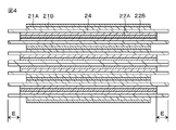
- 6A and 6B are front views and cross-sectional views for explaining Examples 1 and 2, Comparative Examples 1 to 3 and Example 11.
- 7A to 7E are diagrams for explaining Examples 12 to 16.
- 8A to 8D are diagrams for explaining Examples 17 to 20.
- Embodiment> There are two types of batteries, one is a wound battery in which a positive electrode and a negative electrode are laminated and wound via a separator, and the other is a laminated battery in which a positive electrode and a negative electrode are alternately laminated via a separator. There is. The following is a general description of the wound battery and the laminated battery.
- FIG. 1 is an exploded perspective view showing an example of a wound battery using a laminated material, which is an example of the battery of the present invention.
- the battery shown in the figure is configured by enclosing a battery element 20 to which a positive electrode tab (positive electrode terminal) 11 and a negative electrode tab (negative electrode terminal) 12 are attached inside a film-shaped exterior member 30 (30A, 30B). ..
- a part of the positive electrode tab 11 and the negative electrode tab 12 is led out from the inside of the exterior member 30 toward the outside, for example, in the same direction, and the other part extends into the battery element 20.
- the positive electrode tab 11 and the negative electrode tab 12 are each made of a metal material such as aluminum (Al), copper (Cu), nickel (Ni), or stainless steel.
- the exterior member 30 is made of, for example, a rectangular laminated film in which a nylon film, an aluminum foil, and a polyethylene film are laminated in this order.
- the exterior member 30 is arranged so that, for example, the polyethylene film side and the battery element 20 face each other, and the outer edge portions thereof are joined to each other by fusion or adhesive.
- a close contact film 31 for preventing the intrusion of outside air is inserted between the exterior member 30 and the positive electrode tab 11 and the negative electrode tab 12.
- the adhesion film 31 is made of a material having adhesion to the positive electrode tab 11 and the negative electrode tab 12, and for example, when the positive electrode tab 11 and the negative electrode tab 12 are made of the above-mentioned metal material, polyethylene, polypropylene, or modification is used. It is preferably composed of a polyolefin resin such as polyethylene or modified polypropylene.
- the exterior member 30 may be formed of another structure, for example, a laminated film having no metal material, a polymer film such as polypropylene, or a metal film, instead of the above-mentioned laminated film.
- the general configuration of the exterior member can be represented by a laminated structure of an exterior layer / metal foil / sealant layer (however, the exterior layer and the sealant layer may be composed of a plurality of layers).
- the nylon film corresponds to the exterior layer
- the aluminum foil corresponds to the metal foil
- the polyethylene film corresponds to the sealant layer.
- the metal foil it is sufficient if it functions as a moisture-permeable barrier film, and not only aluminum foil but also stainless foil, nickel foil, plated iron foil, etc. can be used, but it is thin and lightweight. Therefore, an aluminum foil having excellent workability can be preferably used.
- FIG. 2 is a cross-sectional view of the battery element 20 shown in FIG. 1 along the line I-I.
- the positive electrode 21 and the negative electrode 22 are located so as to face each other via the separator 24 and are wound around the battery element 20, and the outermost peripheral portion thereof is protected by the protective tape 25.
- the battery element 20 is filled with a non-aqueous electrolytic solution (not shown), and the positive electrode 21, the negative electrode 22, and the separator 24 are impregnated with the non-aqueous electrolytic solution.
- FIG. 3 shows an exploded perspective view showing another example of the battery of the present invention, which is a laminated battery using a laminated material.
- the members substantially the same as those of the wound type battery described above are designated by the same reference numerals, and the description thereof will be omitted.
- this laminated battery has substantially the same configuration as the wound battery shown in FIG. 1 except that the laminated battery element 20'is provided in place of the battery element 20 described above. It has.
- the laminated battery element 20' has a sheet-shaped positive electrode and a negative electrode located opposite each other via a separator, and has, for example, a laminated structure in which a negative electrode sheet, a separator, and a positive electrode sheet are laminated in this order. There is. Similar to the case of the battery element 20, the battery element 20'is filled with a non-aqueous electrolytic solution (not shown), and the positive electrode 21, the negative electrode 22 and the separator 24 are impregnated with the non-aqueous electrolytic solution.
- the positive electrode 21 has a structure in which, for example, a positive electrode active material layer 21B is coated on both sides or one side of a positive electrode current collector 21A having a pair of facing surfaces.
- the positive electrode current collector 21A has a portion exposed without being covered with the positive electrode active material layer 21B at one end in the longitudinal direction, and a positive electrode tab 11 is attached to this exposed portion.
- the positive electrode current collector 21A is composed of a metal foil such as an aluminum foil, a nickel foil or a stainless steel foil.
- the positive electrode active material layer 21B contains, as a positive electrode active material (or a positive electrode mixture), any one or more of positive electrode materials capable of occluding and releasing lithium ions, and if necessary. May contain a conductive material and a binder.
- lithium-containing compounds are preferable because they can obtain high voltage and high energy density.
- examples of such a lithium-containing compound include a composite oxide containing lithium and a transition metal element, and a phosphoric acid compound containing lithium and a transition metal element.
- cobalt is particularly used.
- Such lithium-containing compounds are typically represented by the following general formula (1) or (2).
- Li y M II PO 4 ... (2) ( MI and M II in the formula indicate one or more kinds of transition metal elements, and the values of x and y vary depending on the charge / discharge state of the battery, but usually 0.05 ⁇ x ⁇ 1.10, 0.05 ⁇ . It is represented by y ⁇ 1.10), the compound of the formula (1) generally has a layered structure, and the compound of the formula (2) generally has an olivine structure.
- the composite oxide containing lithium and a transition metal element include a lithium cobalt composite oxide (Li x CoO 2 ), a lithium nickel composite oxide (LixNiO 2 ), and a lithium nickel cobalt composite oxide (Li x ).
- a lithium cobalt composite oxide Li x CoO 2
- a lithium nickel composite oxide LiixNiO 2
- a lithium nickel cobalt composite oxide Li x
- examples thereof include Ni 1-z Coz O 2 (0 ⁇ z ⁇ 1) and a lithium manganese composite oxide having a spinel-type structure (LiMn 2 O 4 ).
- the phosphoric acid compound containing lithium and the transition metal element include, for example, a lithium iron phosphoric acid compound (LiFePO 4 ) having an olivine structure or a lithium iron manganese phosphoric acid compound (LiFe 1-v Mn v PO 4 (v ⁇ ). 1)) can be mentioned.
- a part of the transition metal is replaced with Al, Mg or other transition metal elements or contained in the grain boundaries, and a part of oxygen is fluorine. It can also be mentioned that it is replaced with the above.
- at least a part of the surface of the positive electrode active material may be coated with another positive electrode active material.
- a plurality of types of positive electrode active materials may be mixed and used.
- the negative electrode 22 has a structure in which the negative electrode active material layer 22B is provided on both sides or one side of the negative electrode current collector 22A having a pair of facing surfaces, for example, like the positive electrode 21.
- the negative electrode current collector 22A has a portion exposed without the negative electrode active material layer 22B provided at one end in the longitudinal direction, and the negative electrode tab 12 is attached to this exposed portion.
- the negative electrode current collector 22A is composed of a metal foil such as a copper foil, a nickel foil or a stainless steel foil.
- the negative electrode active material layer 22B contains, as a negative electrode active material (or a negative electrode mixture), one or more of a negative electrode material capable of storing and releasing lithium ions and metallic lithium. , If necessary, a conductive material or a binder may be contained.
- Examples of the negative electrode material capable of occluding and releasing lithium include carbon materials, metal oxides and polymer compounds.
- Examples of the carbon material include non-graphitizable carbon materials, artificial graphite materials, graphite-based materials, and more specifically, thermally decomposed carbons, cokes, graphites, glassy carbons, and fired organic polymer compounds.
- coke includes pitch coke, needle coke, petroleum coke, etc.
- organic polymer compound calcined body is carbonized by calcining a polymer material such as phenol resin or furan resin at an appropriate temperature.
- a polymer material such as phenol resin or furan resin
- the metal oxide include iron oxide, ruthenium oxide and molybdenum oxide
- the polymer compound include polyacetylene and polypyrrole.
- examples of the negative electrode material capable of occluding and releasing lithium include a material containing at least one of a metal element and a metalloid element capable of forming an alloy with lithium as a constituent element.
- the negative electrode material may be a simple substance, an alloy, or a compound of a metal element or a metalloid element, or may have one or more of these phases in at least a part thereof.
- the alloy includes not only an alloy composed of two or more kinds of metal elements but also an alloy containing one or more kinds of metal elements and one or more kinds of metalloid elements. It may also contain non-metal elements.
- Some of the structures include solid solutions, eutectics (eutectic mixtures), intermetallic compounds, or two or more of these coexisting.
- metal elements or metalloid elements examples include tin (Sn), lead (Pb), aluminum, indium (In), silicon (Si), zinc (Zn), antimony (Sb), bismuth (Bi), and the like.
- examples thereof include gallium (Ga), germanium (Ge), arsenic (As), silver (Ag), hafnium (Hf), zirconium (Zr) and yttrium (Y).
- group 14 metal elements or metalloid elements in the long periodic table are preferable, and silicon or tin is particularly preferable. This is because silicon and tin have a large ability to occlude and release lithium, and a high energy density can be obtained.
- an alloy of silicon for example, as a second constituent element other than silicon, a group consisting of tin, magnesium, nickel, copper, iron, cobalt, manganese, zinc, indium, silver, titanium, germanium, bismuth, antimony and chromium. Those containing at least one of them can be mentioned.
- tin compound or the silicon compound examples include those containing oxygen (O) or carbon (C), and may contain the above-mentioned second constituent element in addition to tin or silicon.
- the separator 24 is a porous film made of a polyolefin-based synthetic resin such as polypropylene (melting point: around 165 ° C.) or polyethylene (melting point: around 135 ° C.), or a porous material made of an inorganic material such as a ceramic non-woven fabric. It is composed of an insulating thin film having high ion permeability and predetermined mechanical strength, such as a film, and may have a structure in which two or more kinds of these porous films are laminated.
- a polyolefin-based porous film containing a porous film is suitable because it has excellent separability between the positive electrode 21 and the negative electrode 22 and can further reduce an internal short circuit and a decrease in the open circuit voltage.
- FIG. 4 shows a cross section parallel to the winding direction of the battery element 20 shown in FIG. 1, that is, a cross section taken along the line II-II (III of the laminated battery element 20'shown in FIG. 3). -The same applies to the cross-sectional view taken along the line III or IV-IV), in the battery of the present invention, the ends of the separator 24 are arranged so as to protrude by a predetermined length E from the ends of the positive electrode 21 and the negative electrode 22. Has been done.
- the separator 24 protrudes when the separator 24 and the electrodes 21 and 22 are heat-sealed in the battery manufacturing process. Since the ends are heat-sealed at the same time, it is possible to obtain a battery that does not cause an internal short circuit even by a drop test without installing a new process or increasing man-hours.
- the protrusion length E of the separator 24 needs to be 0.3 mm or more from the viewpoint of causing heat fusion as described above, but this heat fusion is further ensured. If the protrusion length is too large, the volume loss of that portion will be large, so it is desirable to control it within the range of 0.5 to 1.0 mm.
- the non-aqueous electrolyte solution may be any one containing an electrolyte salt and a non-aqueous solvent.
- the electrolyte salt may be any one that dissolves or disperses in a non-aqueous solvent described later to generate ions, and lithium hexafluorophosphate (LiPF 6 ) can be preferably used. It goes without saying that it is not limited.
- lithium tetrafluoroborate LiBF 4
- lithium hexafluoride arsenate LiAsF 6
- lithium hexafluoroantimonate LiSbF 6
- lithium perchlorate LiClO 4
- lithium tetrachloride Lithium tetrachloride
- Inorganic lithium salts such as LiAlCl 4 ), lithium trifluoromethanesulfonate (LiCF 3 SO 3 ), lithium bis (trifluoromethane sulfone) imide (LiN (CF 3 SO 2 ) 2 ), lithium bis (pentafluoromethane sulfone) methide.
- lithium salts of perfluoroalkane sulfonic acid derivatives such as lithium tris (trifluoromethanesulfon) methide (LiC (CF 3 SO 2 ) 3 ) can also be used. It is also possible to use these alone or in combination of two or more.
- the content of such an electrolyte salt is preferably in the range of 0.1 mol to 3.0 mol, more preferably in the range of 0.5 mol to 2.0 mol with respect to 1 liter (l) of the solvent. This is because higher ionic conductivity can be obtained within this range.
- non-aqueous solvent examples include various high dielectric constant solvents and low viscosity solvents.
- Ethylene carbonate, propylene carbonate and the like can be preferably used as the high dielectric constant solvent, but the solvent is not limited to this, but butylene carbonate, vinylene carbonate, 4-fluoro-1,3-dioxolane-2-one.
- Cyclic carbonates such as (fluoroethylene carbonate), 4-chloro-1,3-dioxolane-2-one (chloroethylene carbonate), and trifluoromethylethylene carbonate can be used.
- lactones such as ⁇ -butyrolactone and ⁇ -valerolactone
- lactams such as N-methylpyrrolidone
- cyclic carbamate esters such as N-methyloxazolidinone
- Sulfone compounds such as tetramethylene sulfone can also be used.
- diethyl carbonate can be preferably used as the low-viscosity solvent, but in addition to this, chain carbonates such as dimethyl carbonate, ethyl methyl carbonate and methyl propyl carbonate, methyl acetate, ethyl acetate and methyl propionate are used.
- chain carboxylic acid esters such as ethyl propionate, propyl propionate, methyl butyrate, methyl isobutyrate, methyl trimethyl acetate and ethyl trimethyl acetate
- chain amides such as N, N-dimethylacetamide, N, N-diethylcarbamic acid.
- Chain carbamate esters such as methyl and ethyl N, N-diethylcarbamate, and ethers such as 1,2-dimethoxyethane, tetrahydrofuran, tetrahydropyran and 1,3-dioxolane can be used.
- one of the above-mentioned high dielectric constant solvent and low-viscosity solvent can be used alone or in admixture of two or more.
- a cyclic carbonate having a boiling point of about 50% and a low-viscosity solvent (low-viscosity non-aqueous solvent) of 50 to 80% is preferable, and a chain carbonate having a boiling point of 130 ° C. or lower is particularly preferable as the low-viscosity solvent.
- the dielectric constant becomes low when the low-viscosity solvent is too large, and conversely, the viscosity becomes low when the low-viscosity solvent is too low. In either case, sufficient conductivity may not be obtained and good battery characteristics may not be obtained.
- the filling amount of the non-aqueous electrolytic solution in the battery of the present invention is in the range of 0.14 to 0.35 g per 1 cm 3 of the battery capacity. That is, if the filling amount of the non-aqueous electrolytic solution is less than 0.14 g per unit capacity, the desired battery performance cannot be obtained, and if it exceeds 0.35 g, the liquid leakage resistance tends to deteriorate.
- the mixture was mixed, and this was added to N-methylpyrrolidone, which is a dispersion medium, to prepare a mixture slurry.
- this mixture slurry was applied to a positive electrode current collector 21A made of aluminum having a thickness of 12 ⁇ m, dried, and pressed to form a positive electrode active material layer 21B to prepare a positive electrode.
- the negative electrode 22 is manufactured.
- graphite particles, a binder (SBR + CMC), and a conductive auxiliary agent were mixed as active materials at each weight ratio and diluted with water to prepare a negative electrode slurry.
- the above slurry was uniformly applied onto a copper foil and dried to prepare an electrode. By heat-treating this electrode at 200 ° C., the binding property of the negative electrode active material was improved.
- This electrode was slit to a width of 80 mm to form an uncoated portion, which was used as a place to attach the negative electrode tab 12.
- the positive electrode tab 11 is attached to the positive electrode 21 by welding
- the negative electrode tab 12 is attached to the negative electrode 22 by welding.
- the oriented polystyrene tape 42 is straddled over the winding end portion (winding end end portion) 51 of the positive electrode or the negative electrode on the outermost peripheral portion.
- the battery element 20 was created by arranging (pasting) the battery element 20. The battery element 20 was pressed at a pressure of 1 N / cm 2 to shape it.
- this battery element is sandwiched between exterior members 30 (30A and 30B), and the outer peripheral edge portion excluding one side is heat-sealed to form a bag shape.
- a non-aqueous electrolytic solution containing an electrolyte salt such as lithium hexafluorophosphate and a non-aqueous solvent such as ethyl propionate (EP) and propyl propionate (PP) was prepared, and the non-aqueous electrolytic solution was prepared from the opening of the exterior member 30. It was injected into the battery element 20. The injected battery element 20 is left to be impregnated for 48 hours, heated to 60 ° C., charged to full charge while being pressurized at 20 kgf / cm 2 , and an adhesive layer is formed between the separator 24 and the electrodes 21 and 22. Formed. Then, the opening of the exterior member 30 was heat-sealed and sealed. As a result, the batteries shown in FIGS. 1 and 2 were completed.
- an electrolyte salt such as lithium hexafluorophosphate
- a non-aqueous solvent such as ethyl propionate (EP) and propyl propionate (PP)
- lithium ions are released from the positive electrode active material layer 21B and stored in the negative electrode active material layer 22B via the non-aqueous electrolytic solution.
- the electric discharge is performed, lithium ions are released from the negative electrode active material layer 22B and are occluded in the positive electrode active material layer 21B via the non-aqueous electrolytic solution.
- the present invention will be specifically described based on an example of a drop test using the battery (winding type battery) manufactured as described above.
- the present invention is not limited to the examples described below.
- the oriented polystyrene tape 42 was attached to the flat portion 20A on one main surface of the battery element 20.
- the oriented polystyrene tape 42 is a fixing member for fixing the winding end portion 51 of the battery element 20, and is a single member. Further, the oriented polystyrene tape 42 is provided between the battery element 20 and the exterior member 30 that covers the battery element 20. Double-sided tape was attached to one main surface of the exterior member 30 and the housing (the housing of the electronic device to which the battery is applied), and the exterior member 30 was fixed to the housing.
- FIG. 5 is a schematic diagram of the battery element 20.
- the oriented polystyrene tape 42 and the like are not shown.
- the portions indicated by the broken lines adjacent to the portions indicated by the solid lines are the extending portions 11A, respectively.
- the area of the battery element 20 is the product of the width K of the positive electrode current collector 21A (Al foil) and the width L of the battery element 20, and the area value.
- FIG. 6A is a schematic diagram of the battery element 20.
- oriented polystyrene tape 42 having various widths and areas is applied to the winding end portion 51 of the battery element 20 between the extending portion 11A of the positive electrode tab 11 and the extending portion 12A of the negative electrode tab 12.
- the winding end portion 51 was attached to the position so as to overlap the center of the oriented polystyrene tape 42, and the difference due to the size of the oriented polystyrene tape 42 was investigated.
- "overlapping" means not only covering directly above, but also when the battery element 20 shown in FIG.
- the oriented polystyrene tape 42 is 3052DR manufactured by Tapex Co., Ltd., and is an oriented tape using polystyrene stretched on a base material.
- FIG. 6B is a schematic cross-sectional view when FIG. 6A is cut in the horizontal direction of the figure.
- the positive electrode tab 11 and the negative electrode tab 12 are not shown.
- the outermost circumference of the battery element 20 of FIG. 6A extends from the right side of the figure toward the left side of the figure, and the right side of the drawing is the winding end portion 51 rather than the winding end portion 51. From the left side of the figure, it is larger toward the outside of one round of the battery element 20.
- the portion M surrounded by the alternate long and short dash line on the right side of the winding end portion 51 is the positive electrode current collector 21A (Al foil) on the outermost circumference of the battery element 20 and the positive electrode current collector 21A on the innermost circumference of the battery element 20.
- a portion facing the (Al foil) (hereinafter referred to as a facing portion A) is included.
- the portion N surrounded by the alternate long and short dash line on the left side of the winding end portion 51 in the figure is the positive electrode active material layer 21B coated with the positive electrode mixture and the negative electrode active material layer 22B coated with the negative electrode mixture. Includes a portion facing each other (hereinafter, referred to as a facing portion B) via a separator (not shown).
- the area ratio is defined as the area S of the oriented polystyrene tape 42 attached to the flat portion 20A divided by the area of the battery element 20 when the flat portion 20A of the battery element 20 is viewed in a plan view.
- Drop tests were conducted and evaluated for the above Examples and Comparative Examples.
- the drop test is a test in which a smartphone containing a battery is dropped from a height of 0.5 m in the test machine using a rotating drum tester. A jig with the same weight as a smartphone was prepared, a battery was installed in the jig, and a drop test was conducted. The drop test is repeated, and the state of the battery is checked every 100 times. If the exterior member 30 is damaged and the electrolytic solution leaks, or if the voltage is 3 V or less due to an internal short circuit, the positive electrode tab 11 and the negative electrode tab 12 are torn. The number of times that the impedance measurement is impossible or the smoke is ignited is considered NG as the case where the smartphone is assumed to have stopped working or the smartphone is assumed to have shut down. Was the number of drop tests. The results are shown in Table 1.
- Examples 1 and 2 had a relatively large number of drop tests as compared with the results of Comparative Examples 1 to 3. Since it can be said that the larger the number of drop tests, the greater the impact resistance, it can be determined from Table 1 that the battery is resistant to impact due to dropping or the like when the area ratio is 0.40 or more.
- FIGS. 8A to 8D are schematic views of the battery element 20 to which the oriented polystyrene tape 42 is attached to various places.
- Example 15 The number of drop tests from Example 11 to Example 20 was relatively large compared to Comparative Example 1 to Comparative Example 3 in Table 1. Although the area ratio of Example 15 and Example 16 is almost the same, the number of drop tests of Example 15 is larger than that of Example 16. This is because, in Example 15, the ratio of the area of the oriented polystyrene tape occupying the left side of FIG. 6A from the winding end portion 51 is relatively large, and in Example 16, the oriented polystyrene tape occupying the right side of FIG. 6A from the winding end portion 51. It is considered that the ratio of the area of 42 is relatively large.
- Example 11 and 14 to 18 and 20 the heating test results were OK, whereas in Examples 13 and 19, the heating test results were NG. ..
- Example 13 and Example 19 the oriented polystyrene tape 42 is attached so as to overlap the two extending portions 11A and 12A.
- the oriented polystyrene tape 42 is both the extending portion 11A of the positive electrode tab 11 and the extending portion 12A of the negative electrode tab 12. It is attached so that it does not overlap with.
- the portion attached to the flat portion 20A of the oriented polystyrene tape 42 is arranged in a region of the flat portion 20A that does not include the extending portion 11A of the positive electrode tab 11 or the extending portion 12A of the negative electrode tab 12.
- the absence of the oriented polystyrene tape 42 improves the heat dissipation of the heat generated from the positive electrode tab 11 or the negative electrode tab 12. Therefore, the heating test result is OK, and it can be judged that the battery is resistant to heat from the outside.
- the area ratio is 0.72 or less, it is considered that the oriented polystyrene tape 42 does not excessively cover the battery element 20 and the heat dissipation is improved. Therefore, even if the amount of the oriented polystyrene tape 42 used is small. , It can be judged that the battery is resistant to heat from the outside. Further, from the results of Example 1, Example 19, and Example 20, when the oriented polystyrene tape 42 is attached along the direction in which the positive electrode tab 11 and the negative electrode tab 12 extend, the battery is impacted by dropping or the like. It can be judged that it is strong against.
- the area ratio is the same, when the ratio of the area where the oriented polystyrene tape 42 is attached so as to overlap the facing portion B is larger than the ratio of the area where the oriented polystyrene tape 42 is attached so as to overlap the facing portion A. , It can be judged that the battery is strong against impact caused by dropping.
- the oriented polystyrene tape 42 may be a double-sided tape having an adhesive on both sides. In that case, the oriented polystyrene tape 42 may be adhered to the exterior member 30 and the battery element 20 and the exterior member 30 may be fixed. .. An adhesive may be arranged on the side opposite to the adhesive of the oriented polystyrene tape 42, and the oriented polystyrene tape 42 may also be adhered to the exterior member 30.
- the area of the flat portion of the battery element 20 is the product of the width K of the positive electrode current collector 21A (Al foil) and the width L of the battery element 20, and the value is 3854.4 mm 2 , but other battery sizes. May be.
- a part of the oriented polystyrene tape 42 may be attached to a portion other than the flat portion 20A.
- the electronic device according to the present invention is not limited to a smartphone, and may be a wearable device, a power tool, or the like.
Landscapes
- Engineering & Computer Science (AREA)
- Manufacturing & Machinery (AREA)
- Chemical & Material Sciences (AREA)
- Chemical Kinetics & Catalysis (AREA)
- Electrochemistry (AREA)
- General Chemical & Material Sciences (AREA)
- Secondary Cells (AREA)
Abstract
The present invention provides a battery which has high impact resistance with respect to impact when dropped or the like. A secondary battery which comprises a battery element that is obtained by stacking a positive electrode and a negative electrode with a separator being interposed therebetween, an outer package member in which the battery element is contained, and a fixation member, wherein: the battery element has a flat part to which at least a part of the fixation member is bonded; and an area ratio, which is a value obtained by dividing an area of the fixation member, said area being bonded to the flat part, by the area of the battery element when the flat part of the battery element is viewed in plan, is 0.40 or more.
Description
本発明は、二次電池に関する。
The present invention relates to a secondary battery.
スマートフォンなどのリチウムイオン電池を電源とした電子機器は、様々な用途に利用されている。電子機器は、携帯されて移動されることもあるから、携帯中のアクシデント、例えば、落下などによる衝撃に耐える構造が必要とされている。
Electronic devices powered by lithium-ion batteries such as smartphones are used for various purposes. Since electronic devices may be carried and moved, there is a need for a structure that can withstand an accident during carrying, for example, an impact caused by dropping.
特許文献1は、扁平形状となるように巻回された正極と負極とセパレータとの最外周端部を固定した固定用テープを、平板状の正極タブ及び又は負極タブの主面に対向する1つの扁平面上であり、且つ、平面視で正極タブ及び負極タブと重ならない位置に存在させた電池を開示している。
In Patent Document 1, a fixing tape for fixing the outermost peripheral ends of a positive electrode, a negative electrode, and a separator wound so as to have a flat shape is opposed to a flat positive electrode tab and / or a main surface of a negative electrode tab. Disclosed is a battery that is present on one flat surface and at a position that does not overlap with the positive electrode tab and the negative electrode tab in a plan view.
しかしながら、特許文献1に記載の技術では、電池を落下した場合など、外的衝撃が加わることにより、電池内部での短絡が発生し、電池が非常に高温になる虞があるという問題があった。
However, the technique described in Patent Document 1 has a problem that a short circuit occurs inside the battery due to an external impact such as when the battery is dropped, and the battery may become extremely hot. ..
従って、本発明は、高い耐衝撃性を有する電池を提供することを目的の一つとする。
Therefore, one of the objects of the present invention is to provide a battery having high impact resistance.
上述した課題を解決するために、本発明は、
正極と負極とがセパレータを介して積層された電池素子と、
電池素子を収容する外装部材と、
固定部材と、を有し、
電池素子は、平坦部を有し、
固定部材の少なくとも一部が平坦部に貼付されており、
固定部材のうち平坦部に貼付されている面積を、電池素子の平坦部を平面視した際の電池素子の面積で除した値を面積比とするとき、当該面積比が0.40以上である、
二次電池である。 In order to solve the above-mentioned problems, the present invention
A battery element in which a positive electrode and a negative electrode are laminated via a separator,
Exterior members that house battery elements and
With a fixing member,
The battery element has a flat portion and has a flat portion.
At least a part of the fixing member is attached to the flat part,
The area ratio is 0.40 or more when the value obtained by dividing the area of the fixing member attached to the flat portion by the area of the battery element when the flat portion of the battery element is viewed in a plan view is taken as the area ratio. ,
It is a secondary battery.
本発明の少なくとも実施の形態によれば、高い耐衝撃性を有する電池を提供できる。なお、本明細書で例示された効果により本発明の内容が限定して解釈されるものではない。
According to at least an embodiment of the present invention, it is possible to provide a battery having high impact resistance. It should be noted that the contents of the present invention are not limitedly interpreted by the effects exemplified in the present specification.
以下、本発明の実施の形態等について図面を参照しながら説明する。なお、説明は以下の順序で行う。
<1.一実施の形態>
<2.変形例>
以下に説明する実施の形態等は本発明の好適な具体例であり、本発明の内容がこれらの実施の形態等に限定されるものではない。 Hereinafter, embodiments and the like of the present invention will be described with reference to the drawings. The explanation will be given in the following order.
<1. Embodiment>
<2. Modification example>
The embodiments described below are suitable specific examples of the present invention, and the contents of the present invention are not limited to these embodiments and the like.
<1.一実施の形態>
電池は、正極と負極とがセパレータを介して積層され巻回された巻回型電池である場合と、正極と負極とがセパレータを介して交互に積層された積層型電池である場合の2通りがある。以下で、巻回型電池と積層型電池との一般的な説明をする。 <1. Embodiment>
There are two types of batteries, one is a wound battery in which a positive electrode and a negative electrode are laminated and wound via a separator, and the other is a laminated battery in which a positive electrode and a negative electrode are alternately laminated via a separator. There is. The following is a general description of the wound battery and the laminated battery.
図1は、本発明の電池の一例であって、ラミネート材を用いた巻回型電池の一例を示す分解斜視図である。図に示す電池は、正極タブ(正極端子)11と負極タブ(負極端子)12が取り付けられた電池素子20をフィルム状の外装部材30(30A,30B)の内部に封入して構成されている。正極タブ11及び負極タブ12の一部は、外装部材30の内部から外部に向かって、例えば同一方向にそれぞれ導出されており、他の一部は電池素子20内に延在している。正極タブ11及び負極タブ12は、例えばアルミニウム(Al)、銅(Cu)、ニッケル(Ni)、又はステンレスなどの金属材料によりそれぞれ構成される。
FIG. 1 is an exploded perspective view showing an example of a wound battery using a laminated material, which is an example of the battery of the present invention. The battery shown in the figure is configured by enclosing a battery element 20 to which a positive electrode tab (positive electrode terminal) 11 and a negative electrode tab (negative electrode terminal) 12 are attached inside a film-shaped exterior member 30 (30A, 30B). .. A part of the positive electrode tab 11 and the negative electrode tab 12 is led out from the inside of the exterior member 30 toward the outside, for example, in the same direction, and the other part extends into the battery element 20. The positive electrode tab 11 and the negative electrode tab 12 are each made of a metal material such as aluminum (Al), copper (Cu), nickel (Ni), or stainless steel.
外装部材30は、例えばナイロンフィルム、アルミニウム箔及びポリエチレンフィルムをこの順に張り合わせた矩形状のラミネートフィルムにより構成されている。外装部材30は、例えばポリエチレンフィルム側と電池素子20とが対向するように配設されており、各外縁部が融着又は接着剤により互いに接合されている。
The exterior member 30 is made of, for example, a rectangular laminated film in which a nylon film, an aluminum foil, and a polyethylene film are laminated in this order. The exterior member 30 is arranged so that, for example, the polyethylene film side and the battery element 20 face each other, and the outer edge portions thereof are joined to each other by fusion or adhesive.
外装部材30と正極タブ11及び負極タブ12との間には、外気の侵入を防止するための密着フィルム31が挿入されている。密着フィルム31は、正極タブ11及び負極タブ12に対して密着性を有する材料により構成され、例えば正極タブ11及び負極タブ12が上述した金属材料から構成される場合には、ポリエチレン、ポリプロピレン、変性ポリエチレン又は変性ポリプロピレンなどのポリオレフィン樹脂により構成されることが好ましい。
A close contact film 31 for preventing the intrusion of outside air is inserted between the exterior member 30 and the positive electrode tab 11 and the negative electrode tab 12. The adhesion film 31 is made of a material having adhesion to the positive electrode tab 11 and the negative electrode tab 12, and for example, when the positive electrode tab 11 and the negative electrode tab 12 are made of the above-mentioned metal material, polyethylene, polypropylene, or modification is used. It is preferably composed of a polyolefin resin such as polyethylene or modified polypropylene.
なお、外装部材30は、上述したラミネートフィルムに代えて、他の構造、例えば金属材料を有さないラミネートフィルム、ポリプロピレンなどの高分子フィルム又は金属フィルムなどにより構成してもよい。ここで、外装部材の一般的な構成は、外装層/金属箔/シーラント層の積層構造で表すことができ(但し、外装層及びシーラント層は複数層で構成されることがある。)、上記の例では、ナイロンフィルムが外装層、アルミニウム箔が金属箔、ポリエチレンフィルムがシーラント層に相当する。なお、金属箔としては、耐透湿性のバリア膜として機能すれば十分であり、アルミニウム箔のみならず、ステンレス箔、ニッケル箔及びメッキを施した鉄箔などを使用することができるが、薄く軽量で加工性に優れるアルミニウム箔を好適に用いることができる。
The exterior member 30 may be formed of another structure, for example, a laminated film having no metal material, a polymer film such as polypropylene, or a metal film, instead of the above-mentioned laminated film. Here, the general configuration of the exterior member can be represented by a laminated structure of an exterior layer / metal foil / sealant layer (however, the exterior layer and the sealant layer may be composed of a plurality of layers). In the example, the nylon film corresponds to the exterior layer, the aluminum foil corresponds to the metal foil, and the polyethylene film corresponds to the sealant layer. As the metal foil, it is sufficient if it functions as a moisture-permeable barrier film, and not only aluminum foil but also stainless foil, nickel foil, plated iron foil, etc. can be used, but it is thin and lightweight. Therefore, an aluminum foil having excellent workability can be preferably used.
外装部材として、使用可能な構成を(外装層/金属箔/シーラント層)の形式で列挙すると、Ny(ナイロン)/Al(アルミ)/CPP(無延伸ポリプロピレン)、PET(ポリエチレンテレフタレート)/Al/CPP、PET/Al/PET/CPP、PET/Ny/Al/CPP、PET/Ny/Al/Ny/CPP、PET/Ny/Al/Ny/PE(ポリエチレン)、Ny/PE/Al/LLDPE(直鎖状低密度ポリエチレン)、PET/PE/Al/PET/LDPE(低密度ポリエチレン)、及びPET/Ny/Al/LDPE/CPPなどがある。
Listing the configurations that can be used as exterior members in the form of (exterior layer / metal foil / sealant layer), Ny (nylon) / Al (aluminum) / CPP (unstretched polypropylene), PET (polyethylene terephthalate) / Al / CPP, PET / Al / PET / CPP, PET / Ny / Al / CPP, PET / Ny / Al / Ny / CPP, PET / Ny / Al / Ny / PE (polyethylene), Ny / PE / Al / LLDPE (direct) Chain low density polyethylene), PET / PE / Al / PET / LDPE (low density polyethylene), PET / Ny / Al / LDPE / CPP and the like.
図2は、図1に示した電池素子20のI-I線に沿った断面図である。同図において、電池素子20は、正極21と負極22とがセパレータ24を介して対向して位置し、巻回されているものであり、最外周部は保護テープ25により保護されている。電池素子20内には非水電解液(不図示)が満たされており、正極21、負極22およびセパレータ24が非水電解液に含浸されている。
FIG. 2 is a cross-sectional view of the battery element 20 shown in FIG. 1 along the line I-I. In the figure, in the battery element 20, the positive electrode 21 and the negative electrode 22 are located so as to face each other via the separator 24 and are wound around the battery element 20, and the outermost peripheral portion thereof is protected by the protective tape 25. The battery element 20 is filled with a non-aqueous electrolytic solution (not shown), and the positive electrode 21, the negative electrode 22, and the separator 24 are impregnated with the non-aqueous electrolytic solution.
ここで、図3には、本発明の電池の他の例であって、ラミネート材を用いた積層型電池を示す分解斜視図を示す。なお、上述した巻回型電池と実質的に同一の部材には同一符号を付し、その説明を省略する。図3に示すように、この積層型電池は、上記の電池素子20の代わりに積層電池素子20’を備えていること以外は、図1に示した巻回型電池と実質的に同一の構成を有するものである。
Here, FIG. 3 shows an exploded perspective view showing another example of the battery of the present invention, which is a laminated battery using a laminated material. The members substantially the same as those of the wound type battery described above are designated by the same reference numerals, and the description thereof will be omitted. As shown in FIG. 3, this laminated battery has substantially the same configuration as the wound battery shown in FIG. 1 except that the laminated battery element 20'is provided in place of the battery element 20 described above. It has.
積層電池素子20’は、シート状をなす正極と負極とがセパレータを介して対向して位置しており、例えば、負極シート、セパレータ、及び正極シートの順で積層された積層構造を有している。電池素子20の場合と同様に、電池素子20’内には非水電解液(不図示)が満たされており、正極21、負極22およびセパレータ24が非水電解液に含浸されている。
The laminated battery element 20'has a sheet-shaped positive electrode and a negative electrode located opposite each other via a separator, and has, for example, a laminated structure in which a negative electrode sheet, a separator, and a positive electrode sheet are laminated in this order. There is. Similar to the case of the battery element 20, the battery element 20'is filled with a non-aqueous electrolytic solution (not shown), and the positive electrode 21, the negative electrode 22 and the separator 24 are impregnated with the non-aqueous electrolytic solution.
図2に示すように、正極21は、例えば対向する1対の面を有する正極集電体21Aの両面又は片面に正極活物質層21Bが被覆された構造を有している。正極集電体21Aには、長手方向における一方の端部に正極活物質層21Bが被覆されずに露出している部分があり、この露出部分に正極タブ11が取り付けられている。
As shown in FIG. 2, the positive electrode 21 has a structure in which, for example, a positive electrode active material layer 21B is coated on both sides or one side of a positive electrode current collector 21A having a pair of facing surfaces. The positive electrode current collector 21A has a portion exposed without being covered with the positive electrode active material layer 21B at one end in the longitudinal direction, and a positive electrode tab 11 is attached to this exposed portion.
正極集電体21Aは、例えばアルミニウム箔、ニッケル箔又はステンレス箔などの金属箔により構成される。正極活物質層21Bは、正極活物質(又は正極合材と称する)として、リチウムイオンを吸蔵及び放出することが可能な正極材料のいずれか1種又は2種以上を含んでおり、必要に応じて導電材及び結着剤を含んでいてもよい。
The positive electrode current collector 21A is composed of a metal foil such as an aluminum foil, a nickel foil or a stainless steel foil. The positive electrode active material layer 21B contains, as a positive electrode active material (or a positive electrode mixture), any one or more of positive electrode materials capable of occluding and releasing lithium ions, and if necessary. May contain a conductive material and a binder.
これらの中でも、リチウム含有化合物は、高電圧及び高エネルギー密度を得ることができるものがあるので好ましい。このようなリチウム含有化合物としては、例えばリチウムと遷移金属元素とを含む複合酸化物や、リチウムと遷移金属元素とを含むリン酸化合物が挙げられるが、より高い電圧を得る観点からは、特にコバルト(Co)、ニッケル(Ni)、マンガン(Mn)、鉄(Fe)、銅(Cu)、亜鉛(Zn)、クロム(Cr)、バナジウム(V)、チタン(Ti)、又はこれらの任意の混合物を含むものが好ましい。
Among these, lithium-containing compounds are preferable because they can obtain high voltage and high energy density. Examples of such a lithium-containing compound include a composite oxide containing lithium and a transition metal element, and a phosphoric acid compound containing lithium and a transition metal element. From the viewpoint of obtaining a higher voltage, cobalt is particularly used. (Co), nickel (Ni), manganese (Mn), iron (Fe), copper (Cu), zinc (Zn), chromium (Cr), vanadium (V), titanium (Ti), or any mixture thereof. Is preferable.
かかるリチウム含有化合物は、代表的には、次の一般式(1)又は(2)
LixMIO2・・・(1)
LiyMIIPO4・・・(2)
(式中のMI及びMIIは1種類以上の遷移金属元素を示し、x及びyの値は電池の充放電状態によって異なるが、通常0.05≦x≦1.10、0.05≦y≦1.10である。)で表され、(1)式の化合物は一般に層状構造を有し、(2)式の化合物は一般にオリビン構造を有する。 Such lithium-containing compounds are typically represented by the following general formula (1) or (2).
Li x MIO 2 ... ( 1 )
Li y M II PO 4 ... (2)
( MI and M II in the formula indicate one or more kinds of transition metal elements, and the values of x and y vary depending on the charge / discharge state of the battery, but usually 0.05 ≦ x ≦ 1.10, 0.05 ≦. It is represented by y ≦ 1.10), the compound of the formula (1) generally has a layered structure, and the compound of the formula (2) generally has an olivine structure.
また、リチウムと遷移金属元素とを含む複合酸化物の具体例としては、リチウムコバルト複合酸化物(LixCoO2)、リチウムニッケル複合酸化物(LixNiO2)、リチウムニッケルコバルト複合酸化物(LixNi1-zCozO2(0<z<1)、スピネル型構造を有するリチウムマンガン複合酸化物(LiMn2O4)などが挙げられる。
Specific examples of the composite oxide containing lithium and a transition metal element include a lithium cobalt composite oxide (Li x CoO 2 ), a lithium nickel composite oxide (LixNiO 2 ), and a lithium nickel cobalt composite oxide (Li x ). Examples thereof include Ni 1-z Coz O 2 (0 <z <1) and a lithium manganese composite oxide having a spinel-type structure (LiMn 2 O 4 ).
リチウムと遷移金属元素とを含むリン酸化合物の具体例としては、例えばオリビン構造を有するリチウム鉄リン酸化合物(LiFePO4)又はリチウム鉄マンガンリン酸化合物(LiFe1-vMnvPO4(v<1))が挙げられる。これらの複合酸化物において、構造を安定化させる等の目的から、遷移金属の一部をAlやMgその他の遷移金属元素で置換したり結晶粒界に含ませたもの、酸素の一部をフッ素等で置換したもの等も挙げることができる。更に、正極活物質表面の少なくとも一部に他の正極活物質を被覆したものとしてもよい。また、正極活物質は、複数種類を混合して用いてもよい。
Specific examples of the phosphoric acid compound containing lithium and the transition metal element include, for example, a lithium iron phosphoric acid compound (LiFePO 4 ) having an olivine structure or a lithium iron manganese phosphoric acid compound (LiFe 1-v Mn v PO 4 (v <). 1)) can be mentioned. In these composite oxides, for the purpose of stabilizing the structure, a part of the transition metal is replaced with Al, Mg or other transition metal elements or contained in the grain boundaries, and a part of oxygen is fluorine. It can also be mentioned that it is replaced with the above. Further, at least a part of the surface of the positive electrode active material may be coated with another positive electrode active material. Further, a plurality of types of positive electrode active materials may be mixed and used.
一方、負極22は、正極21と同様に、例えば対向する一対の面を有する負極集電体22Aの両面又は片面に負極活物質層22Bが設けられた構造を有している。負極集電体22Aには、長手方向における一方の端部に負極活物質層22Bが設けられず露出している部分があり、この露出部分に負極タブ12が取り付けられている。
On the other hand, the negative electrode 22 has a structure in which the negative electrode active material layer 22B is provided on both sides or one side of the negative electrode current collector 22A having a pair of facing surfaces, for example, like the positive electrode 21. The negative electrode current collector 22A has a portion exposed without the negative electrode active material layer 22B provided at one end in the longitudinal direction, and the negative electrode tab 12 is attached to this exposed portion.
負極集電体22Aは、例えば銅箔、ニッケル箔又はステンレス箔などの金属箔により構成される。負極活物質層22Bは、負極活物質(又は負極合材と称する。)として、リチウムイオンを吸蔵及び放出することが可能な負極材料、金属リチウムのいずれか1種又は2種以上を含んでおり、必要に応じて導電材や結着剤を含んでいてもよい。リチウムを吸蔵及び放出することが可能な負極材料としては、例えば炭素材料、金属酸化物及び高分子化合物が挙げられる。炭素材料としては、難黒鉛化炭素材料、人造黒鉛材料や黒鉛系材料などが挙げられ、より具体的には、熱分解炭素類、コークス類、黒鉛類、ガラス状炭素類、有機高分子化合物焼成体、炭素繊維、活性炭及びカーボンブラックなどがある。
The negative electrode current collector 22A is composed of a metal foil such as a copper foil, a nickel foil or a stainless steel foil. The negative electrode active material layer 22B contains, as a negative electrode active material (or a negative electrode mixture), one or more of a negative electrode material capable of storing and releasing lithium ions and metallic lithium. , If necessary, a conductive material or a binder may be contained. Examples of the negative electrode material capable of occluding and releasing lithium include carbon materials, metal oxides and polymer compounds. Examples of the carbon material include non-graphitizable carbon materials, artificial graphite materials, graphite-based materials, and more specifically, thermally decomposed carbons, cokes, graphites, glassy carbons, and fired organic polymer compounds. There are bodies, carbon fiber, activated carbon and carbon black.
このうち、コークス類にはピッチコークス、ニードルコークス及び石油コークスなどがあり、有機高分子化合物焼成体というのは、フェノール樹脂やフラン樹脂などの高分子材料を適当な温度で焼成して炭素化したものをいう。また、金属酸化物としては、酸化鉄、酸化ルテニウム及び酸化モリブデンなどが挙げられ、高分子化合物としてはポリアセチレンやポリピロールなどが挙げられる。
Among these, coke includes pitch coke, needle coke, petroleum coke, etc., and the organic polymer compound calcined body is carbonized by calcining a polymer material such as phenol resin or furan resin at an appropriate temperature. Say something. Examples of the metal oxide include iron oxide, ruthenium oxide and molybdenum oxide, and examples of the polymer compound include polyacetylene and polypyrrole.
更に、リチウムを吸蔵及び放出することが可能な負極材料としては、リチウムと合金を形成可能な金属元素及び半金属元素のうちの少なくとも1種を構成元素として含む材料も挙げられる。この負極材料は金属元素又は半金属元素の単体でも合金でも化合物でもよく、またこれらの1種又は2種以上の相を少なくとも一部に有するようなものでもよい。なお、本発明において、合金には2種以上の金属元素からなるものに加えて、1種以上の金属元素と1種以上の半金属元素とを含むものも含める。また、非金属元素を含んでいてもよい。その組織には固溶体、共晶(共融混合物)、金属間化合物又はこれらのうちの2種以上が共存するものがある。
Further, examples of the negative electrode material capable of occluding and releasing lithium include a material containing at least one of a metal element and a metalloid element capable of forming an alloy with lithium as a constituent element. The negative electrode material may be a simple substance, an alloy, or a compound of a metal element or a metalloid element, or may have one or more of these phases in at least a part thereof. In the present invention, the alloy includes not only an alloy composed of two or more kinds of metal elements but also an alloy containing one or more kinds of metal elements and one or more kinds of metalloid elements. It may also contain non-metal elements. Some of the structures include solid solutions, eutectics (eutectic mixtures), intermetallic compounds, or two or more of these coexisting.
このような金属元素又は半金属元素としては、例えばスズ(Sn)、鉛(Pb)、アルミニウム、インジウム(In)、ケイ素(Si)、亜鉛(Zn)、アンチモン(Sb)、ビスマス(Bi)、ガリウム(Ga)、ゲルマニウム(Ge)、ヒ素(As)、銀(Ag)、ハフニウム(Hf)、ジルコニウム(Zr)及びイットリウム(Y)が挙げられる。中でも、長周期型周期表における14族の金属元素又は半金属元素が好ましく、特に好ましいのはケイ素又はスズである。ケイ素及びスズは、リチウムを吸蔵及び放出する能力が大きく、高いエネルギー密度を得ることができるからである。
Examples of such metal elements or metalloid elements include tin (Sn), lead (Pb), aluminum, indium (In), silicon (Si), zinc (Zn), antimony (Sb), bismuth (Bi), and the like. Examples thereof include gallium (Ga), germanium (Ge), arsenic (As), silver (Ag), hafnium (Hf), zirconium (Zr) and yttrium (Y). Among them, group 14 metal elements or metalloid elements in the long periodic table are preferable, and silicon or tin is particularly preferable. This is because silicon and tin have a large ability to occlude and release lithium, and a high energy density can be obtained.
ケイ素の合金としては、例えばケイ素以外の第2の構成元素として、スズ、マグネシウム、ニッケル、銅、鉄、コバルト、マンガン、亜鉛、インジウム、銀、チタン、ゲルマニウム、ビスマス、アンチモン及びクロムから成る群のうちの少なくとも1種を含むものが挙げられる。
As an alloy of silicon, for example, as a second constituent element other than silicon, a group consisting of tin, magnesium, nickel, copper, iron, cobalt, manganese, zinc, indium, silver, titanium, germanium, bismuth, antimony and chromium. Those containing at least one of them can be mentioned.
スズの化合物又はケイ素の化合物としては、例えば酸素(O)又は炭素(C)を含むものが挙げられ、スズまたはケイ素に加えて、上述した第2の構成元素を含んでいてもよい。
Examples of the tin compound or the silicon compound include those containing oxygen (O) or carbon (C), and may contain the above-mentioned second constituent element in addition to tin or silicon.
また、セパレータ24は、例えばポリプロピレン(融点:165℃前後)若しくはポリエチレン(融点:135℃前後)などのポリオレフィン系の合成樹脂から成る多孔質膜、又はセラミック製の不織布などの無機材料から成る多孔質膜など、イオン透過度が大きく、所定の機械的強度を有する絶縁性の薄膜から構成されており、これら2種以上の多孔質膜を積層した構造としてもよい。特に、ポリオレフィン系の多孔質膜を含むものは、正極21と負極22との分離性に優れ、内部短絡や開回路電圧の低下をいっそう低減できるので好適である。
Further, the separator 24 is a porous film made of a polyolefin-based synthetic resin such as polypropylene (melting point: around 165 ° C.) or polyethylene (melting point: around 135 ° C.), or a porous material made of an inorganic material such as a ceramic non-woven fabric. It is composed of an insulating thin film having high ion permeability and predetermined mechanical strength, such as a film, and may have a structure in which two or more kinds of these porous films are laminated. In particular, a polyolefin-based porous film containing a porous film is suitable because it has excellent separability between the positive electrode 21 and the negative electrode 22 and can further reduce an internal short circuit and a decrease in the open circuit voltage.
図4は、図1に示した電池素子20の巻回方向と平行な断面、すなわちII-II線に沿った断面図を示すものであって(図3に示した積層電池素子20’のIII-III線又はIV-IV線に沿った断面図も同様)、本発明の電池においては、上記セパレータ24の端部が正極21及び負極22の端から所定の長さEだけ突出するように配置されている。
FIG. 4 shows a cross section parallel to the winding direction of the battery element 20 shown in FIG. 1, that is, a cross section taken along the line II-II (III of the laminated battery element 20'shown in FIG. 3). -The same applies to the cross-sectional view taken along the line III or IV-IV), in the battery of the present invention, the ends of the separator 24 are arranged so as to protrude by a predetermined length E from the ends of the positive electrode 21 and the negative electrode 22. Has been done.
このように、セパレータ24の端部を正極21及び負極22の端から突出させておくことによって、電池の製造工程において、セパレータ24と電極21、22を熱融着させる際に、セパレータ24の突出端部同士が同時に熱融着することになるので、工程を新設したり、工数を増したりすることなく、落下試験によっても内部短絡することのない電池を得ることができる。
By projecting the end of the separator 24 from the ends of the positive electrode 21 and the negative electrode 22 in this way, the separator 24 protrudes when the separator 24 and the electrodes 21 and 22 are heat-sealed in the battery manufacturing process. Since the ends are heat-sealed at the same time, it is possible to obtain a battery that does not cause an internal short circuit even by a drop test without installing a new process or increasing man-hours.
なお、セパレータ24の突出長さEとしては、上記のような熱融着を生じさせる観点から、0.3mm以上とすることが必要であるが、この熱融着をさらに確実なものとする一方、突出長さが大きすぎると、その部分の体積ロスが大きくなるので、0.5~1.0mmの範囲に制御することが望ましい。
The protrusion length E of the separator 24 needs to be 0.3 mm or more from the viewpoint of causing heat fusion as described above, but this heat fusion is further ensured. If the protrusion length is too large, the volume loss of that portion will be large, so it is desirable to control it within the range of 0.5 to 1.0 mm.
非水電解液としては、電解質塩と非水溶媒を含むものであればよい。ここで、電解質塩としては、後述する非水溶媒に溶解ないしは分散してイオンを生ずるものであればよく、六フッ化リン酸リチウム(LiPF6)を好適に使用することができるが、これに限定されないことはいうまでもない。
The non-aqueous electrolyte solution may be any one containing an electrolyte salt and a non-aqueous solvent. Here, the electrolyte salt may be any one that dissolves or disperses in a non-aqueous solvent described later to generate ions, and lithium hexafluorophosphate (LiPF 6 ) can be preferably used. It goes without saying that it is not limited.
すなわち、四フッ化ホウ酸リチウム(LiBF4)、六フッ化ヒ酸リチウム(LiAsF6)、六フッ化アンチモン酸リチウム(LiSbF6)、過塩素酸リチウム(LiClO4)、四塩化アルミニウム酸リチウム(LiAlCl4)等の無機リチウム塩や、トリフルオロメタンスルホン酸リチウム(LiCF3SO3)、リチウムビス(トリフルオロメタンスルホン)イミド(LiN(CF3SO2)2)、リチウムビス(ペンタフルオロメタンスルホン)メチド(LiN(C2F5SO2)2)、及びリチウムトリス(トリフルオロメタンスルホン)メチド(LiC(CF3SO2)3)等のパーフルオロアルカンスルホン酸誘導体のリチウム塩なども使用可能であり、これらを1種単独で又は2種以上を組み合わせて使用することも可能である。
That is, lithium tetrafluoroborate (LiBF 4 ), lithium hexafluoride arsenate (LiAsF 6 ), lithium hexafluoroantimonate (LiSbF 6 ), lithium perchlorate (LiClO 4 ), lithium tetrachloride (Lithium tetrachloride) ( Inorganic lithium salts such as LiAlCl 4 ), lithium trifluoromethanesulfonate (LiCF 3 SO 3 ), lithium bis (trifluoromethane sulfone) imide (LiN (CF 3 SO 2 ) 2 ), lithium bis (pentafluoromethane sulfone) methide. (LiN (C 2 F 5 SO 2 ) 2 ) and lithium salts of perfluoroalkane sulfonic acid derivatives such as lithium tris (trifluoromethanesulfon) methide (LiC (CF 3 SO 2 ) 3 ) can also be used. It is also possible to use these alone or in combination of two or more.
なお、このような電解質塩の含有量は、溶媒1リットル(l)に対して0.1mol~3.0molの範囲内が好ましく、0.5mol~2.0molの範囲内であればより好ましい。この範囲内においてより高いイオン伝導性を得ることができるからである。
The content of such an electrolyte salt is preferably in the range of 0.1 mol to 3.0 mol, more preferably in the range of 0.5 mol to 2.0 mol with respect to 1 liter (l) of the solvent. This is because higher ionic conductivity can be obtained within this range.
また、非水溶媒としては、各種の高誘電率溶媒や低粘度溶媒を挙げることができる。高誘電率溶媒としては、エチレンカーボネートとプロピレンカーボネート等を好適に用いることができるが、これに限定されるものではなく、ブチレンカーボネート、ビニレンカーボネート、4-フルオロ-1,3-ジオキソラン-2-オン(フルオロエチレンカーボネート)、4-クロロ-1,3-ジオキソラン-2-オン(クロロエチレンカーボネート)、及びトリフルオロメチルエチレンカーボネートなどの環状カーボネートを用いることができる。
Further, examples of the non-aqueous solvent include various high dielectric constant solvents and low viscosity solvents. Ethylene carbonate, propylene carbonate and the like can be preferably used as the high dielectric constant solvent, but the solvent is not limited to this, but butylene carbonate, vinylene carbonate, 4-fluoro-1,3-dioxolane-2-one. Cyclic carbonates such as (fluoroethylene carbonate), 4-chloro-1,3-dioxolane-2-one (chloroethylene carbonate), and trifluoromethylethylene carbonate can be used.
また、高誘電率溶媒として、環状カーボネートの代わりに又はこれと併用して、γ-ブチロラクトン及びγ-バレロラクトン等のラクトン、N-メチルピロリドン等のラクタム、N-メチルオキサゾリジノン等の環状カルバミン酸エステル、テトラメチレンスルホン等のスルホン化合物なども使用可能である。
Further, as a high dielectric constant solvent, instead of or in combination with the cyclic carbonate, lactones such as γ-butyrolactone and γ-valerolactone, lactams such as N-methylpyrrolidone, and cyclic carbamate esters such as N-methyloxazolidinone. , Sulfone compounds such as tetramethylene sulfone can also be used.
一方、低粘度溶媒としては、ジエチルカーボネートを好適に使用することができるが、これ以外にも、ジメチルカーボネート、エチルメチルカーボネート及びメチルプロピルカーボネート等の鎖状カーボネート、酢酸メチル、酢酸エチル、プロピオン酸メチル、プロピオン酸エチル、プロピオン酸プロピル、酪酸メチル、イソ酪酸メチル、トリメチル酢酸メチル及びトリメチル酢酸エチル等の鎖状カルボン酸エステル、N,N-ジメチルアセトアミド等の鎖状アミド、N,N-ジエチルカルバミン酸メチル及びN,N-ジエチルカルバミン酸エチル等の鎖状カルバミン酸エステル、並びに1,2-ジメトキシエタン、テトラヒドロフラン、テトラヒドロピラン及び1,3-ジオキソラン等のエーテルを用いることができる。
On the other hand, diethyl carbonate can be preferably used as the low-viscosity solvent, but in addition to this, chain carbonates such as dimethyl carbonate, ethyl methyl carbonate and methyl propyl carbonate, methyl acetate, ethyl acetate and methyl propionate are used. , Chain carboxylic acid esters such as ethyl propionate, propyl propionate, methyl butyrate, methyl isobutyrate, methyl trimethyl acetate and ethyl trimethyl acetate, chain amides such as N, N-dimethylacetamide, N, N-diethylcarbamic acid. Chain carbamate esters such as methyl and ethyl N, N-diethylcarbamate, and ethers such as 1,2-dimethoxyethane, tetrahydrofuran, tetrahydropyran and 1,3-dioxolane can be used.
なお、本発明の電池に用いる非水電解液としては、上述の高誘電率溶媒及び低粘度溶媒は、その1種を単独で又は2種以上を任意に混合して用いることができるが、20~50%の環状カーボネートと50~80%の低粘度溶媒(低粘度非水溶媒)を含むものが好ましく、特に低粘度溶媒として沸点が130℃以下の鎖状カーボネートであるものが望ましい。
As the non-aqueous electrolyte solution used in the battery of the present invention, one of the above-mentioned high dielectric constant solvent and low-viscosity solvent can be used alone or in admixture of two or more. A cyclic carbonate having a boiling point of about 50% and a low-viscosity solvent (low-viscosity non-aqueous solvent) of 50 to 80% is preferable, and a chain carbonate having a boiling point of 130 ° C. or lower is particularly preferable as the low-viscosity solvent.
環状カーボネートと低粘度溶媒との比率が上述の範囲を逸脱すると、低粘度溶媒が多すぎる場合には誘電率が低くなり、逆に低粘度溶媒が少なすぎる場合には粘度が低くなってしまい、どちらの場合にも十分な伝導度が得られず、良好な電池特性が得られなくなるおそれがある。
If the ratio of the cyclic carbonate to the low-viscosity solvent deviates from the above range, the dielectric constant becomes low when the low-viscosity solvent is too large, and conversely, the viscosity becomes low when the low-viscosity solvent is too low. In either case, sufficient conductivity may not be obtained and good battery characteristics may not be obtained.
本発明の電池内への非水電解液の充填量については、電池容量1cm3あたり0.14~0.35gの範囲とすることが望ましい。すなわち、非水電解液の充填量が単位容量あたり0.14gに満たないと、所期の電池性能が得られず、0.35gを超えると耐漏液性が劣化する傾向がある。
It is desirable that the filling amount of the non-aqueous electrolytic solution in the battery of the present invention is in the range of 0.14 to 0.35 g per 1 cm 3 of the battery capacity. That is, if the filling amount of the non-aqueous electrolytic solution is less than 0.14 g per unit capacity, the desired battery performance cannot be obtained, and if it exceeds 0.35 g, the liquid leakage resistance tends to deteriorate.
次に、上述した電池の製造方法の一例を説明する。まず、正極21を作製する。正極21は、前記のコバルト酸リチウムの粉末と、導電材であるカーボンブラックと、バインダーであるポリフッ化ビニリデンとを、正極活物質:カーボンブラック:ポリフッ化ビニリデン=96:1:3の質量比で混合し、これを分散媒であるN-メチルピロリドンへ投入して合剤スラリーとした。その後、この合剤スラリーを厚み12μmのアルミニウムよりなる正極集電体21Aに塗布して乾燥させ、加圧して正極活物質層21Bを形成し、正極を作製した。
Next, an example of the above-mentioned battery manufacturing method will be described. First, the positive electrode 21 is manufactured. The positive electrode 21 contains the above-mentioned lithium cobalt oxide powder, carbon black as a conductive material, and polyvinylidene fluoride as a binder in a mass ratio of positive electrode active material: carbon black: polyvinylidene fluoride = 96: 1: 3. The mixture was mixed, and this was added to N-methylpyrrolidone, which is a dispersion medium, to prepare a mixture slurry. Then, this mixture slurry was applied to a positive electrode current collector 21A made of aluminum having a thickness of 12 μm, dried, and pressed to form a positive electrode active material layer 21B to prepare a positive electrode.
次に、負極22を作製する。負極22は、活物質として黒鉛粒子とバインダー(SBR+CMC)、導電助剤を各重量比で混合し、水で希釈して負極スラリーを作成した。上記スラリーを銅箔上に均一に塗布し乾燥させ、電極を作成した。この電極を200℃で熱処理することで、負極活物質の結着性を向上させた。この電極を、幅80mmにスリットし、非被覆部を作製し、負極タブ12を取り付ける場所とした。
Next, the negative electrode 22 is manufactured. For the negative electrode 22, graphite particles, a binder (SBR + CMC), and a conductive auxiliary agent were mixed as active materials at each weight ratio and diluted with water to prepare a negative electrode slurry. The above slurry was uniformly applied onto a copper foil and dried to prepare an electrode. By heat-treating this electrode at 200 ° C., the binding property of the negative electrode active material was improved. This electrode was slit to a width of 80 mm to form an uncoated portion, which was used as a place to attach the negative electrode tab 12.
次いで、正極21に正極タブ11を溶接により取り付けるとともに、負極22に負極タブ12を溶接により取り付けた後、セパレータ24、正極21、同様のセパレータ24及び負極22を順次積層して巻回し、以下の図6A、図7A~図7E及び図8A~図8Dに示されるように、最外周部にある正極又は負極の巻き終わり部(巻き終わり端部)51を跨ぐようにして、配向ポリスチレンテープ42を配置し(貼付し)、電池素子20を作成した。電池素子20を、1N/cm2の圧力でプレスして形状を整えた。
Next, the positive electrode tab 11 is attached to the positive electrode 21 by welding, and the negative electrode tab 12 is attached to the negative electrode 22 by welding. As shown in FIGS. 6A, 7A to 7E, and 8A to 8D, the oriented polystyrene tape 42 is straddled over the winding end portion (winding end end portion) 51 of the positive electrode or the negative electrode on the outermost peripheral portion. The battery element 20 was created by arranging (pasting) the battery element 20. The battery element 20 was pressed at a pressure of 1 N / cm 2 to shape it.
更に、この電池素子を外装部材30(30Aと30B)で挟み、一辺を除く外周縁部を熱融着して袋状とする。
Further, this battery element is sandwiched between exterior members 30 (30A and 30B), and the outer peripheral edge portion excluding one side is heat-sealed to form a bag shape.
しかる後、六フッ化リン酸リチウムなどの電解質塩と、プロピオン酸エチル(EP)やプロピオン酸プロピル(PP)などの非水溶媒を含む非水電解液を準備し、外装部材30の開口部から電池素子20の内部に注入した。注液した電池素子20は、48時間放置含浸させ、60℃に加温し、20kgf/cm2で加圧しながら満充電まで充電して、セパレータ24と電極21,22との間に接着層を形成させた。そして、外装部材30の開口部を熱融着し封入した。これにより、図1及び図2に示した電池を完成させた。
After that, a non-aqueous electrolytic solution containing an electrolyte salt such as lithium hexafluorophosphate and a non-aqueous solvent such as ethyl propionate (EP) and propyl propionate (PP) was prepared, and the non-aqueous electrolytic solution was prepared from the opening of the exterior member 30. It was injected into the battery element 20. The injected battery element 20 is left to be impregnated for 48 hours, heated to 60 ° C., charged to full charge while being pressurized at 20 kgf / cm 2 , and an adhesive layer is formed between the separator 24 and the electrodes 21 and 22. Formed. Then, the opening of the exterior member 30 was heat-sealed and sealed. As a result, the batteries shown in FIGS. 1 and 2 were completed.
以上に説明した電池では、充電を行うと、正極活物質層21Bからリチウムイオンが放出され、非水電解液を介して負極活物質層22Bに吸蔵される。放電を行うと、負極活物質層22Bからリチウムイオンが放出され、非水電解液を介して正極活物質層21Bに吸蔵される。
In the battery described above, when charging is performed, lithium ions are released from the positive electrode active material layer 21B and stored in the negative electrode active material layer 22B via the non-aqueous electrolytic solution. When the electric discharge is performed, lithium ions are released from the negative electrode active material layer 22B and are occluded in the positive electrode active material layer 21B via the non-aqueous electrolytic solution.
以下、上記のようにして作製した電池(巻回型電池)を用いて、落下試験についての実施例に基づいて本発明を具体的に説明する。なお、本発明は、以下に説明する実施例に限定されるものではない。
Hereinafter, the present invention will be specifically described based on an example of a drop test using the battery (winding type battery) manufactured as described above. The present invention is not limited to the examples described below.
電池素子20の一方の主面にある平坦部20Aに配向ポリスチレンテープ42を貼付した。配向ポリスチレンテープ42は電池素子20の巻き終わり部51を固定するための固定部材であり、単一の部材である。また、配向ポリスチレンテープ42は、電池素子20と当該電池素子20を覆う外装部材30との間に設けられている。外装部材30の一方の主面と筐体(電池が適用される電子機器の筐体)とに両面テープを貼り付け、外装部材30を筐体に固定した。
The oriented polystyrene tape 42 was attached to the flat portion 20A on one main surface of the battery element 20. The oriented polystyrene tape 42 is a fixing member for fixing the winding end portion 51 of the battery element 20, and is a single member. Further, the oriented polystyrene tape 42 is provided between the battery element 20 and the exterior member 30 that covers the battery element 20. Double-sided tape was attached to one main surface of the exterior member 30 and the housing (the housing of the electronic device to which the battery is applied), and the exterior member 30 was fixed to the housing.
図5は、電池素子20の概略図である。なお、図5では配向ポリスチレンテープ42などの図示を省略している。図5において、正極タブ11と負極タブ12のうち、実線で示される部分(電池素子20の外部に導出されている部分)に隣接して破線により示される部分は、それぞれ、延在部11A,12A(正極タブ11と負極タブ12が電池素子20内部において延在している部分)であり、このことは、図6から図8についても同様である。全ての実施例及び比較例において、図5に示されるように、電池素子20の面積を、正極集電体21A(Al箔)の幅Kと電池素子20の幅Lの積とし、面積の値を3854.4mm2とした。図6Aは電池素子20の概略図である。図6Aに示されるように、電池素子20の巻き終わり部51に、様々な幅と面積の配向ポリスチレンテープ42を、正極タブ11の延在部11Aと負極タブ12の延在部12Aの中間の位置に、巻き終わり部51が配向ポリスチレンテープ42の中央に重なるように貼付し、配向ポリスチレンテープ42の大きさによる違いを調べた。なお、本明細書において、「重なる」とは、直上を覆うことだけではなく、図6Aなどに示される電池素子20を平面視したときに内部の物を覆うように配置された場合、例えば、内部の物が延在部11A,12Aの投影領域に配置されている場合や、図6Bに示すように、断面を視た場合、積層している場合を含む。配向ポリスチレンテープ42はTapex社製の3052DRであり、基材に延伸させたポリスチレンを用いた配向性のあるテープである。
FIG. 5 is a schematic diagram of the battery element 20. In FIG. 5, the oriented polystyrene tape 42 and the like are not shown. In FIG. 5, of the positive electrode tab 11 and the negative electrode tab 12, the portions indicated by the broken lines adjacent to the portions indicated by the solid lines (the portions led out to the outside of the battery element 20) are the extending portions 11A, respectively. It is 12A (the portion where the positive electrode tab 11 and the negative electrode tab 12 extend inside the battery element 20), and this also applies to FIGS. 6 to 8. In all the examples and comparative examples, as shown in FIG. 5, the area of the battery element 20 is the product of the width K of the positive electrode current collector 21A (Al foil) and the width L of the battery element 20, and the area value. Was 3854.4 mm 2 . FIG. 6A is a schematic diagram of the battery element 20. As shown in FIG. 6A, oriented polystyrene tape 42 having various widths and areas is applied to the winding end portion 51 of the battery element 20 between the extending portion 11A of the positive electrode tab 11 and the extending portion 12A of the negative electrode tab 12. The winding end portion 51 was attached to the position so as to overlap the center of the oriented polystyrene tape 42, and the difference due to the size of the oriented polystyrene tape 42 was investigated. In addition, in this specification, "overlapping" means not only covering directly above, but also when the battery element 20 shown in FIG. 6A or the like is arranged so as to cover an internal object when viewed in a plan view, for example. This includes the case where the internal object is arranged in the projection area of the extending portions 11A and 12A, the case where the cross section is viewed as shown in FIG. 6B, and the case where the internal objects are stacked. The oriented polystyrene tape 42 is 3052DR manufactured by Tapex Co., Ltd., and is an oriented tape using polystyrene stretched on a base material.
図6Bは、図6Aを図の水平方向に切断したときの概略断面図である。なお、図6Bでは正極タブ11と負極タブ12の図示を省略している。図6Bに示されるように、図6Aの電池素子20の最外周は図の右側から図の左側に向かって延在しており、巻き終わり部51より図の右側の方が、巻き終わり部51より図の左側より、電池素子20の1周分外側に向かって大きい。巻き終わり部51より図の右側にある、一点鎖線で囲まれた部分Mは、電池素子20の最外周の正極集電体21A(Al箔)と最外周より1周内側の正極集電体21A(Al箔)とが対向する部分(以下、対向部Aと称する。)を含んでいる。巻き終わり部51より図の左側にある、一点鎖線で囲まれた部分Nは、正極合材が塗着している正極活物質層21Bと負極合材が塗着している負極活物質層22Bとが、セパレータ(不図示)を介して対向する部分(以下、対向部Bと称する。)を含んでいる。配向ポリスチレンテープ42のうち平坦部20Aに貼付されている面積Sを、電池素子20の平坦部20Aを平面視したときの電池素子20の面積で除した値を面積比と定義した。
FIG. 6B is a schematic cross-sectional view when FIG. 6A is cut in the horizontal direction of the figure. In FIG. 6B, the positive electrode tab 11 and the negative electrode tab 12 are not shown. As shown in FIG. 6B, the outermost circumference of the battery element 20 of FIG. 6A extends from the right side of the figure toward the left side of the figure, and the right side of the drawing is the winding end portion 51 rather than the winding end portion 51. From the left side of the figure, it is larger toward the outside of one round of the battery element 20. The portion M surrounded by the alternate long and short dash line on the right side of the winding end portion 51 is the positive electrode current collector 21A (Al foil) on the outermost circumference of the battery element 20 and the positive electrode current collector 21A on the innermost circumference of the battery element 20. A portion facing the (Al foil) (hereinafter referred to as a facing portion A) is included. The portion N surrounded by the alternate long and short dash line on the left side of the winding end portion 51 in the figure is the positive electrode active material layer 21B coated with the positive electrode mixture and the negative electrode active material layer 22B coated with the negative electrode mixture. Includes a portion facing each other (hereinafter, referred to as a facing portion B) via a separator (not shown). The area ratio is defined as the area S of the oriented polystyrene tape 42 attached to the flat portion 20A divided by the area of the battery element 20 when the flat portion 20A of the battery element 20 is viewed in a plan view.
[実施例1~4]
実施例1については、図6Aに示されるように、長さw=64.5mmであって矩形状の配向ポリスチレンテープ42を、正極タブ11の延在部11Aと負極タブ12の延在部12Aの略中間の位置に、且つ、巻き終わり部51が配向ポリスチレンテープ42の略中央に重なるように貼付した。この際、配向ポリスチレンテープ42を延在部11A,12Aに重ならないように貼付した。配向ポリスチレンテープ42の面積を1729mm2とし、面積比を0.45とした。実施例2~4については、表1の「対応する図」中に示される位置に、実施例1と同じ長さwであり幅が異なる配向ポリスチレンテープ42を貼付した。 [Examples 1 to 4]
For Example 1, as shown in FIG. 6A, a rectangular orientedpolystyrene tape 42 having a length w = 64.5 mm is used with the extending portion 11A of the positive electrode tab 11 and the extending portion 12A of the negative electrode tab 12. It was attached at a position substantially in the middle of the above, and so that the winding end portion 51 overlapped with the substantially center of the oriented polystyrene tape 42. At this time, the oriented polystyrene tape 42 was attached so as not to overlap the extending portions 11A and 12A. The area of the oriented polystyrene tape 42 was 1729 mm 2 , and the area ratio was 0.45. For Examples 2 to 4, oriented polystyrene tape 42 having the same length w as that of Example 1 but having a different width was attached at the positions shown in the “corresponding diagram” of Table 1.
実施例1については、図6Aに示されるように、長さw=64.5mmであって矩形状の配向ポリスチレンテープ42を、正極タブ11の延在部11Aと負極タブ12の延在部12Aの略中間の位置に、且つ、巻き終わり部51が配向ポリスチレンテープ42の略中央に重なるように貼付した。この際、配向ポリスチレンテープ42を延在部11A,12Aに重ならないように貼付した。配向ポリスチレンテープ42の面積を1729mm2とし、面積比を0.45とした。実施例2~4については、表1の「対応する図」中に示される位置に、実施例1と同じ長さwであり幅が異なる配向ポリスチレンテープ42を貼付した。 [Examples 1 to 4]
For Example 1, as shown in FIG. 6A, a rectangular oriented
[評価]
上記の実施例と比較例について、落下試験を行い、評価を行った。落下試験は回転ドラム試験機を用いて、試験機内で0.5mの高さから電池を含むスマートフォンを落下させる試験である。スマートフォンと同じ重量の治具を用意し、治具に電池を設置して、落下試験を行った。落下試験を繰り返し、100回毎に電池の状態を調べ、外装部材30が損傷し電解液の液漏れがある場合、内部ショートにより電圧が3V以下である場合、正極タブ11や負極タブ12が断裂してインピーダンス測定が不能である場合や、発煙発火した場合を、スマートフォンが動作しなくなったと想定される場合、又は、スマートフォンがシャットダウンしたと想定される場合であるとしてNGとし、NGが判明した回数を、落下試験回数とした。結果を表1に示す。 [evaluation]
Drop tests were conducted and evaluated for the above Examples and Comparative Examples. The drop test is a test in which a smartphone containing a battery is dropped from a height of 0.5 m in the test machine using a rotating drum tester. A jig with the same weight as a smartphone was prepared, a battery was installed in the jig, and a drop test was conducted. The drop test is repeated, and the state of the battery is checked every 100 times. If theexterior member 30 is damaged and the electrolytic solution leaks, or if the voltage is 3 V or less due to an internal short circuit, the positive electrode tab 11 and the negative electrode tab 12 are torn. The number of times that the impedance measurement is impossible or the smoke is ignited is considered NG as the case where the smartphone is assumed to have stopped working or the smartphone is assumed to have shut down. Was the number of drop tests. The results are shown in Table 1.
上記の実施例と比較例について、落下試験を行い、評価を行った。落下試験は回転ドラム試験機を用いて、試験機内で0.5mの高さから電池を含むスマートフォンを落下させる試験である。スマートフォンと同じ重量の治具を用意し、治具に電池を設置して、落下試験を行った。落下試験を繰り返し、100回毎に電池の状態を調べ、外装部材30が損傷し電解液の液漏れがある場合、内部ショートにより電圧が3V以下である場合、正極タブ11や負極タブ12が断裂してインピーダンス測定が不能である場合や、発煙発火した場合を、スマートフォンが動作しなくなったと想定される場合、又は、スマートフォンがシャットダウンしたと想定される場合であるとしてNGとし、NGが判明した回数を、落下試験回数とした。結果を表1に示す。 [evaluation]
Drop tests were conducted and evaluated for the above Examples and Comparative Examples. The drop test is a test in which a smartphone containing a battery is dropped from a height of 0.5 m in the test machine using a rotating drum tester. A jig with the same weight as a smartphone was prepared, a battery was installed in the jig, and a drop test was conducted. The drop test is repeated, and the state of the battery is checked every 100 times. If the
[表1]
 [Table 1]
実施例1及び実施例2は比較例1から比較例3までの結果と比較して、落下試験回数が比較的大きかった。落下試験回数は大きいほど耐衝撃性が大きいといえることから、表1より面積比が0.40以上であるとき、電池は、落下などによる衝撃に強いと判断できる。
Examples 1 and 2 had a relatively large number of drop tests as compared with the results of Comparative Examples 1 to 3. Since it can be said that the larger the number of drop tests, the greater the impact resistance, it can be determined from Table 1 that the battery is resistant to impact due to dropping or the like when the area ratio is 0.40 or more.
次に、配向ポリスチレンテープ42の貼付位置による違いを調べた。図7Aから図7E及び図8Aから図8Dは、配向ポリスチレンテープ42を様々な場所に貼付した電池素子20の概略図である。
Next, the difference depending on the attachment position of the oriented polystyrene tape 42 was investigated. 7A to 7E and FIGS. 8A to 8D are schematic views of the battery element 20 to which the oriented polystyrene tape 42 is attached to various places.
[実施例11~20]
実施例11は、実施例2と同様(図6A参照)に、長さw=64.5mmであって矩形状の配向ポリスチレンテープ42を、正極タブ11の延在部11Aと負極タブ12の延在部12Aの略中間の位置に、且つ、巻き終わり部51が配向ポリスチレンテープ42の略中央に重なるように貼付した。この際、配向ポリスチレンテープ42を延在部11A,12Aのそれぞれに重ならないように貼付した。配向ポリスチレンテープ42の面積を1541mm2とし、面積比を0.40とした。実施例12~20については、表2の「対応する図」中に示された位置に矩形状又は凹形状の配向ポリスチレンテープ42を貼付した。 [Examples 11 to 20]
In Example 11, similarly to Example 2 (see FIG. 6A), a rectangular orientedpolystyrene tape 42 having a length w = 64.5 mm is used, and the extending portion 11A of the positive electrode tab 11 and the extending portion of the negative electrode tab 12 are extended. It was attached at a position substantially in the middle of the existing portion 12A and so that the winding end portion 51 overlaps with the substantially center of the oriented polystyrene tape 42. At this time, the oriented polystyrene tape 42 was attached so as not to overlap each of the extending portions 11A and 12A. The area of the oriented polystyrene tape 42 was 1541 mm 2 , and the area ratio was 0.40. For Examples 12 to 20, a rectangular or concave oriented polystyrene tape 42 was attached at the position shown in the “corresponding diagram” of Table 2.
実施例11は、実施例2と同様(図6A参照)に、長さw=64.5mmであって矩形状の配向ポリスチレンテープ42を、正極タブ11の延在部11Aと負極タブ12の延在部12Aの略中間の位置に、且つ、巻き終わり部51が配向ポリスチレンテープ42の略中央に重なるように貼付した。この際、配向ポリスチレンテープ42を延在部11A,12Aのそれぞれに重ならないように貼付した。配向ポリスチレンテープ42の面積を1541mm2とし、面積比を0.40とした。実施例12~20については、表2の「対応する図」中に示された位置に矩形状又は凹形状の配向ポリスチレンテープ42を貼付した。 [Examples 11 to 20]
In Example 11, similarly to Example 2 (see FIG. 6A), a rectangular oriented
[評価]
上記の実施例11から実施例20について、落下試験及び加熱試験を行い、評価を行った。落下試験は上述した方法と同様の方法により行った。加熱試験は、4.43Vに充電した電池を恒温層内に設置し、雰囲気温度を5℃/minで昇温させ、130℃に到達したのち130℃で1時間の保持時間が過ぎるまでに、電池がショート(電圧が2V以下まで低下)した場合、又は電池が発火した場合には、加熱試験結果がNGであるとし、ショートや発火がない場合には加熱試験結果がOKであるとした。結果を表2に示す。 [evaluation]
The above-mentioned Examples 11 to 20 were subjected to a drop test and a heating test and evaluated. The drop test was performed by the same method as described above. In the heating test, a battery charged to 4.43 V was installed in a constant temperature layer, the atmospheric temperature was raised at 5 ° C / min, and after reaching 130 ° C, the holding time at 130 ° C for 1 hour passed. When the battery is short-circuited (voltage drops to 2 V or less) or the battery ignites, the heating test result is NG, and when there is no short-circuit or ignition, the heating test result is OK. The results are shown in Table 2.
[表2]
 [Table 2]
実施例11から実施例20の落下試験回数は、表1の比較例1から比較例3に対して比較的大きかった。実施例15と実施例16は、ほぼ同じ面積比であるが、実施例15の落下試験回数は実施例16より大きな値となった。これは、実施例15は、巻き終わり部51より図6Aの左側に占める配向ポリスチレンテープの面積の割合が比較的大きく、実施例16は、巻き終わり部51より図6Aの右側に占める配向ポリスチレンテープ42の面積の割合が比較的大きいからと考えられる。すなわち、配向ポリスチレンテープ42が図6Bの一点鎖線で囲まれた部分Nの対向部Bに重なるように貼付される面積の割合を、図6B一点鎖線で囲まれた部分Mの対向部Aに重なるように貼付される面積の割合より大きくすることにより、接着強度を大きくすることができるからと考えられる。
The number of drop tests from Example 11 to Example 20 was relatively large compared to Comparative Example 1 to Comparative Example 3 in Table 1. Although the area ratio of Example 15 and Example 16 is almost the same, the number of drop tests of Example 15 is larger than that of Example 16. This is because, in Example 15, the ratio of the area of the oriented polystyrene tape occupying the left side of FIG. 6A from the winding end portion 51 is relatively large, and in Example 16, the oriented polystyrene tape occupying the right side of FIG. 6A from the winding end portion 51. It is considered that the ratio of the area of 42 is relatively large. That is, the ratio of the area where the oriented polystyrene tape 42 is attached so as to overlap the facing portion B of the portion N surrounded by the alternate long and short dash line in FIG. 6B overlaps with the facing portion A of the portion M surrounded by the alternate long and short dash line in FIG. 6B. It is considered that the adhesive strength can be increased by making it larger than the ratio of the area to be attached.
実施例11、実施例12、実施例14から実施例18と実施例20では、加熱試験結果がOKであったのに対し、実施例13と実施例19では、加熱試験結果がNGであった。実施例13と実施例19では、配向ポリスチレンテープ42が2つの延在部11A,12Aに重なるように貼付されていている。これに対して、実施例11、実施例12、実施例14から実施例18と実施例20では、配向ポリスチレンテープ42が正極タブ11の延在部11Aと負極タブ12の延在部12Aの両方に重ならないように貼付されている。実施例13と実施例19の場合は、電池素子20が外装部材30に入れられた後に加圧される工程で、正極タブ11の延在部11Aとその周囲と、負極タブ12の延在部12Aとその周囲とが配向ポリスチレンテープ42によって強く圧迫されるので、加熱試験時にガスが発生しても開裂しづらく、これにより電池素子20が変形することで短絡につながったと考えられる。
In Examples 11, 12, and 14 to 18 and 20, the heating test results were OK, whereas in Examples 13 and 19, the heating test results were NG. .. In Example 13 and Example 19, the oriented polystyrene tape 42 is attached so as to overlap the two extending portions 11A and 12A. On the other hand, in Example 11, Example 12, Examples 14 to 18 and Example 20, the oriented polystyrene tape 42 is both the extending portion 11A of the positive electrode tab 11 and the extending portion 12A of the negative electrode tab 12. It is attached so that it does not overlap with. In the case of Examples 13 and 19, in the step of applying pressure after the battery element 20 is placed in the exterior member 30, the extending portion 11A of the positive electrode tab 11 and its surroundings, and the extending portion of the negative electrode tab 12 Since 12A and its surroundings are strongly pressed by the oriented polystyrene tape 42, it is difficult to cleave even if gas is generated during the heating test, and it is considered that this deforms the battery element 20 and leads to a short circuit.
表2より、面積比が0.40以上であるとき、電池は、落下などによる衝撃に強いと判断できる。さらに、配向ポリスチレンテープ42の平坦部20Aに貼付されている箇所が、平坦部20Aにおける正極タブ11の延在部11Aまたは負極タブ12の延在部12Aの投影領域を含まない領域に配置されているとき、配向ポリスチレンテープ42がないことで、正極タブ11または負極タブ12から生じる熱の放熱性が向上する。このため、加熱試験結果がOKとなり、電池は、外部からの熱にも強いと判断できる。さらに、面積比が0.72以下であると、配向ポリスチレンテープ42が電池素子20を過剰に覆うことがなく放熱性が向上したと考えられることから、配向ポリスチレンテープ42の使用量が少なくても、電池は、外部からの熱にも強いと判断できる。また、実施例1や実施例19、実施例20の結果から、正極タブ11と負極タブ12が延在する方向に沿って配向ポリスチレンテープ42が貼付されているとき、電池が、落下などによる衝撃に強いと判断できる。同様の面積比であるならば、配向ポリスチレンテープ42が対向部Bに重なるように貼付される面積の割合が、配向ポリスチレンテープ42が対向部Aに重なるように貼付される面積の割合より大きいとき、電池は、落下などによる衝撃に強いと判断できる。
From Table 2, when the area ratio is 0.40 or more, it can be judged that the battery is strong against impact due to dropping or the like. Further, the portion attached to the flat portion 20A of the oriented polystyrene tape 42 is arranged in a region of the flat portion 20A that does not include the extending portion 11A of the positive electrode tab 11 or the extending portion 12A of the negative electrode tab 12. When present, the absence of the oriented polystyrene tape 42 improves the heat dissipation of the heat generated from the positive electrode tab 11 or the negative electrode tab 12. Therefore, the heating test result is OK, and it can be judged that the battery is resistant to heat from the outside. Further, when the area ratio is 0.72 or less, it is considered that the oriented polystyrene tape 42 does not excessively cover the battery element 20 and the heat dissipation is improved. Therefore, even if the amount of the oriented polystyrene tape 42 used is small. , It can be judged that the battery is resistant to heat from the outside. Further, from the results of Example 1, Example 19, and Example 20, when the oriented polystyrene tape 42 is attached along the direction in which the positive electrode tab 11 and the negative electrode tab 12 extend, the battery is impacted by dropping or the like. It can be judged that it is strong against. If the area ratio is the same, when the ratio of the area where the oriented polystyrene tape 42 is attached so as to overlap the facing portion B is larger than the ratio of the area where the oriented polystyrene tape 42 is attached so as to overlap the facing portion A. , It can be judged that the battery is strong against impact caused by dropping.
<2.変形例>
以上、本発明の実施の形態について具体的に説明したが、本発明の内容は上述した一実施の形態に限定されるものではなく、本発明の技術的思想に基づく各種の変形が可能である。 <2. Modification example>
Although the embodiments of the present invention have been specifically described above, the content of the present invention is not limited to the above-described embodiment, and various modifications based on the technical idea of the present invention are possible. ..
配向ポリスチレンテープ42は、両面に粘着剤を備えた両面テープであってもよく、その場合、配向ポリスチレンテープ42が外装部材30とも接着され、電池素子20と外装部材30とが固定されてもよい。配向ポリスチレンテープ42の粘着剤とは反対側に接着剤が配置され、配向ポリスチレンテープ42が外装部材30とも接着されていてもよい。
電池素子20の平坦部の面積を、正極集電体21A(Al箔)の幅Kと電池素子20の幅Lの積とし、値が3854.4mm2であるとしたが、それ以外の電池サイズであってもよい。
配向ポリスチレンテープ42の一部が平坦部20A以外の箇所に貼付されていてもよい。 The orientedpolystyrene tape 42 may be a double-sided tape having an adhesive on both sides. In that case, the oriented polystyrene tape 42 may be adhered to the exterior member 30 and the battery element 20 and the exterior member 30 may be fixed. .. An adhesive may be arranged on the side opposite to the adhesive of the oriented polystyrene tape 42, and the oriented polystyrene tape 42 may also be adhered to the exterior member 30.
The area of the flat portion of thebattery element 20 is the product of the width K of the positive electrode current collector 21A (Al foil) and the width L of the battery element 20, and the value is 3854.4 mm 2 , but other battery sizes. May be.
A part of the orientedpolystyrene tape 42 may be attached to a portion other than the flat portion 20A.
電池素子20の平坦部の面積を、正極集電体21A(Al箔)の幅Kと電池素子20の幅Lの積とし、値が3854.4mm2であるとしたが、それ以外の電池サイズであってもよい。
配向ポリスチレンテープ42の一部が平坦部20A以外の箇所に貼付されていてもよい。 The oriented
The area of the flat portion of the
A part of the oriented
本発明に係る電子機器はスマートフォンに限定されることはなく、ウエアラブル機器、電動工具等であってもよい。
The electronic device according to the present invention is not limited to a smartphone, and may be a wearable device, a power tool, or the like.
上述の実施の形態において挙げた構成、方法、工程、形状、材料及び数値などはあくまでも例に過ぎず、必要に応じてこれと異なる構成、方法、工程、形状、材料及び数値などを用いてもよい。上述した実施の形態および変形例は、適宜組み合わせることができる。
The configurations, methods, processes, shapes, materials, numerical values, etc. given in the above-described embodiments are merely examples, and different configurations, methods, processes, shapes, materials, numerical values, etc. may be used as necessary. good. The above-described embodiments and modifications can be combined as appropriate.
11・・・正極タブ,11A・・・延在部,12・・・負極タブ,12A・・・延在部,20・・・巻回電池素子,20’・・・積層電池素子,20A・・・平坦部、21A・・・正極集電体,21B・・・正極活物質層,22A・・・負極集電体,22B・・・負極活物質層,30,30A,30B・・・外装部材,42・・・配向ポリスチレンテープ,51・・・巻き終わり部
11 ... Positive electrode tab, 11A ... Extended part, 12 ... Negative electrode tab, 12A ... Extended part, 20 ... Winding battery element, 20'... Laminated battery element, 20A. Flat portion, 21A ... Positive electrode current collector, 21B ... Positive electrode active material layer, 22A ... Negative electrode current collector, 22B ... Negative electrode active material layer, 30, 30A, 30B ... Exterior Member, 42 ... Oriented polystyrene tape, 51 ... End of winding
Claims (4)
- 正極と負極とがセパレータを介して積層された電池素子と、
前記電池素子を収容する外装部材と、
固定部材と、を有し、
前記電池素子は、平坦部を有し、
前記固定部材の少なくとも一部が前記平坦部に貼付されており、
前記固定部材のうち前記平坦部に貼付されている面積を、前記電池素子の前記平坦部を平面視した際の前記電池素子の面積で除した値を面積比とするとき、当該面積比が0.40以上である、二次電池。 A battery element in which a positive electrode and a negative electrode are laminated via a separator,
An exterior member accommodating the battery element and
With a fixing member,
The battery element has a flat portion and has a flat portion.
At least a part of the fixing member is attached to the flat portion.
When the area of the fixing member attached to the flat portion is divided by the area of the battery element when the flat portion of the battery element is viewed in a plan view, the area ratio is 0. A secondary battery that is .40 or more. - 正極タブと負極タブとを有し、
前記正極タブと前記負極タブとはそれぞれ延在部を有し、
前記延在部は、前記電池素子の内部において延在しており、
前記平坦部に貼付されている前記固定部材の箇所は、前記電池素子の前記平坦部における前記正極タブまたは前記負極タブの前記延在部の投影領域を含まない領域に位置している、請求項1に記載の二次電池。 It has a positive electrode tab and a negative electrode tab,
The positive electrode tab and the negative electrode tab each have an extending portion.
The extending portion extends inside the battery element, and the extending portion extends.
The portion of the fixing member attached to the flat portion is located in a region of the flat portion of the battery element that does not include a projection region of the positive electrode tab or the extending portion of the negative electrode tab. The secondary battery according to 1. - 前記面積比が0.72以下である、請求項1または2に記載の二次電池。 The secondary battery according to claim 1 or 2, wherein the area ratio is 0.72 or less.
- 前記電池素子は、巻回されたものであり、
前記固定部材は、前記電池素子の最外周の正極または負極の巻き終わり端部を跨ぐように貼付されている、請求項1から3までの何れかに記載の二次電池。 The battery element is wound and is wound.
The secondary battery according to any one of claims 1 to 3, wherein the fixing member is attached so as to straddle the winding end end of the positive electrode or the negative electrode on the outermost periphery of the battery element.
Applications Claiming Priority (2)
| Application Number | Priority Date | Filing Date | Title |
|---|---|---|---|
| JP2020-159929 | 2020-09-24 | ||
| JP2020159929 | 2020-09-24 |
Publications (1)
| Publication Number | Publication Date |
|---|---|
| WO2022065129A1 true WO2022065129A1 (en) | 2022-03-31 |
Family
ID=80845301
Family Applications (1)
| Application Number | Title | Priority Date | Filing Date |
|---|---|---|---|
| PCT/JP2021/033677 WO2022065129A1 (en) | 2020-09-24 | 2021-09-14 | Secondary battery |
Country Status (1)
| Country | Link |
|---|---|
| WO (1) | WO2022065129A1 (en) |
Citations (3)
| Publication number | Priority date | Publication date | Assignee | Title |
|---|---|---|---|---|
| JP2003151614A (en) * | 2001-11-16 | 2003-05-23 | Nec Tokin Tochigi Ltd | Sealed battery |
| JP2009289662A (en) * | 2008-05-30 | 2009-12-10 | Sony Corp | Wound electrode body, and nonaqueous electrolyte secondary battery |
| US20180287184A1 (en) * | 2016-06-09 | 2018-10-04 | Lg Chem, Ltd. | Secondary battery |
-
2021
- 2021-09-14 WO PCT/JP2021/033677 patent/WO2022065129A1/en active Application Filing
Patent Citations (3)
| Publication number | Priority date | Publication date | Assignee | Title |
|---|---|---|---|---|
| JP2003151614A (en) * | 2001-11-16 | 2003-05-23 | Nec Tokin Tochigi Ltd | Sealed battery |
| JP2009289662A (en) * | 2008-05-30 | 2009-12-10 | Sony Corp | Wound electrode body, and nonaqueous electrolyte secondary battery |
| US20180287184A1 (en) * | 2016-06-09 | 2018-10-04 | Lg Chem, Ltd. | Secondary battery |
Similar Documents
| Publication | Publication Date | Title |
|---|---|---|
| JP4968182B2 (en) | Winding electrode body and non-aqueous electrolyte secondary battery | |
| US7955731B2 (en) | Nonaqueous electrolyte secondary cell | |
| JP4396675B2 (en) | Nonaqueous electrolyte secondary battery | |
| US10566660B2 (en) | Film packaged battery | |
| US10186691B2 (en) | Battery and assembled battery | |
| US10587002B2 (en) | Secondary battery, method for manufacturing secondary battery, electric vehicle and electricity storage system | |
| JP5168850B2 (en) | Non-aqueous electrolyte secondary battery and method for producing non-aqueous electrolyte secondary battery | |
| JP2013118194A (en) | Pouch, and secondary battery comprising the same | |
| JP2008305662A (en) | Nonaqueous electrolyte secondary battery | |
| JP5509618B2 (en) | Non-aqueous electrolyte composition and non-aqueous electrolyte secondary battery | |
| JP2007335352A (en) | Nonaqueous electrolyte secondary battery and battery control system | |
| JP2008047398A (en) | Nonaqueous electrolyte secondary battery | |
| JP4784730B2 (en) | battery | |
| JP2011159488A (en) | Nonaqueous electrolyte composition, and nonaqueous electrolyte secondary battery | |
| JP5103822B2 (en) | Nonaqueous electrolyte secondary battery | |
| KR101460856B1 (en) | Nonaqueous electrolyte battery, electrode for the same, and battery pack | |
| JP2005209469A (en) | Lithium secondary battery | |
| JP4836612B2 (en) | Nonaqueous electrolyte battery and battery pack | |
| JP2008117614A (en) | Current collector for electrode, and nonaqueous secondary battery | |
| JP2016219387A (en) | Secondary battery | |
| JP5380908B2 (en) | Winding electrode body and non-aqueous electrolyte secondary battery | |
| JP2007194104A (en) | Gelatinous electrolyte battery | |
| WO2022065129A1 (en) | Secondary battery | |
| WO2022113615A1 (en) | Battery | |
| WO2021261083A1 (en) | Cell and electronic device |
Legal Events
| Date | Code | Title | Description |
|---|---|---|---|
| 121 | Ep: the epo has been informed by wipo that ep was designated in this application |
Ref document number: 21872259 Country of ref document: EP Kind code of ref document: A1 |
|
| NENP | Non-entry into the national phase |
Ref country code: DE |
|
| 122 | Ep: pct application non-entry in european phase |
Ref document number: 21872259 Country of ref document: EP Kind code of ref document: A1 |
|
| NENP | Non-entry into the national phase |
Ref country code: JP |